department of computer science and engineering the...
TRANSCRIPT

Department of Computer Science and Engineering
The University of Texas at Arlington
System Test Plan
Team: Kingpin
Project: Pin Deck Camera System
Team Members: Shawn Dobbins
Jason Grey
Eric Nelson
Bhuwan Shrestha
Last Updated: October 1st 2013 10:04am

System Test Plan Pin Deck Tracking System
October 1st, 2013 P a g e | 2 Team Kingpin
Table of Contents
Table of Contents ......................................................................................................................................... 2
List of Figures .............................................................................................................................................. 6
List of Tables ............................................................................................................................................... 7
1. Introduction............................................................................................................................................. 8
1.1 Document Overview and Purpose ................................................................................................. 8
1.2 Scope ............................................................................................................................................. 8
1.3 Acronyms ...................................................................................................................................... 8
2. References ............................................................................................................................................... 9
2.1 Overview ....................................................................................................................................... 9
2.2 System Requirement Specification ............................................................................................... 9
2.2.1 Key Requirements ...................................................................................................................... 9
2.2.2 System Inputs and Outputs ....................................................................................................... 10
2.3 Architecture Design Specification .............................................................................................. 11
2.3.1 Architecture Design Diagram ................................................................................................... 11
2.3.2 Data Flow Definition ........................................................................................................... 12
2.3.3 Producer-Consumer Relationships ...................................................................................... 13
2.3.4 Requirement Mapping .............................................................................................................. 14
2.3.5 Layer Data Descriptions ...................................................................................................... 15
2.4 Detailed Design Specification ..................................................................................................... 16
2.4.1 Detailed Design Diagram ......................................................................................................... 16
2.4.2 Module Data Flows.............................................................................................................. 17
2.4.3 Module Producer/Consumer Matrix .................................................................................... 19
3. Test Items.............................................................................................................................................. 20
3.1 Overview ..................................................................................................................................... 20
3.2 Relational Diagram ..................................................................................................................... 20
3.3 Hardware Tests ........................................................................................................................... 20
3.4 Unit Tests .................................................................................................................................... 21
3.4.1 Interface Layer ..................................................................................................................... 21
3.4.2 Control Layer ....................................................................................................................... 22
System Test Plan Pin Deck Tracking System
October 1st, 2013 P a g e | 3 Team Kingpin
3.4.3 Image Processing Layer ....................................................................................................... 23
3.4.4 File I/O Layer ........................................................................................................................... 24
3.4.5 Image Acquisition Layer .......................................................................................................... 25
3.5 Component Tests......................................................................................................................... 26
3.5.1 Interface Layer ..................................................................................................................... 26
3.5.2 Control Layer ....................................................................................................................... 26
3.5.3 Image Processing Layer ....................................................................................................... 26
3.5.4 File I/O Layer ........................................................................................................................... 27
3.5.5 Image Acquisition Layer .......................................................................................................... 28
3.6 Integration Tests .......................................................................................................................... 28
3.6.1 Interface Layer .......................................................................................................................... 28
3.6.2 Control Layer ............................................................................................................................ 28
3.6.3 Image Processing Layer ............................................................................................................ 29
3.6.4 File I/O Layer ........................................................................................................................... 29
3.6.5 Image Acquisition Layer .......................................................................................................... 29
3.7 System Verification Tests ........................................................................................................... 30
4. Risks ..................................................................................................................................................... 32
4.1 Overview ..................................................................................................................................... 32
4.2 Risk Table ................................................................................................................................... 32
5. Testable Features .................................................................................................................................. 33
5.1 Overview ..................................................................................................................................... 33
5.2 Customer Requirements .............................................................................................................. 33
5.3 Packaging Requirements ............................................................................................................. 36
5.4 Performance Requirements ......................................................................................................... 38
6. Non-Testable Features .......................................................................................................................... 39
6.1 Overview ..................................................................................................................................... 39
6.2 Safety Requirements ................................................................................................................... 39
6.2.1 Camera Mounting ..................................................................................................................... 39
6.2.2 Lighting Mounting .................................................................................................................... 39
6.2.3 Cabling / wiring ........................................................................................................................ 39
6.2.4 User Safety................................................................................................................................ 39
6.3 Maintenance and Support Requirements .................................................................................... 39
System Test Plan Pin Deck Tracking System
October 1st, 2013 P a g e | 4 Team Kingpin
6.3.1 Source Code .............................................................................................................................. 39
6.3.2 Troubleshooting Instructions .................................................................................................... 40
6.3.3 System Maintenance ............................................................................................................ 40
6.3.4 Training................................................................................................................................ 40
6.4.1Windows OS Support ................................................................................................................ 40
6.4.2 Code Modularity ....................................................................................................................... 40
6.4.3 Team Galaxy Interface Integration ............................................................................................... 40
7. Testing Approach/Strategy ................................................................................................................... 41
7.1 Overview ..................................................................................................................................... 41
7.2 Overall Test Strategy .................................................................................................................. 41
7.3 Methodology ............................................................................................................................... 41
7.4 Testing Metrics ........................................................................................................................... 42
7.5 Testing Requirements ................................................................................................................. 42
8. Item Pass/Fail Criteria .......................................................................................................................... 43
8.1 Overview ..................................................................................................................................... 43
8.2 Hardware Tests ........................................................................................................................... 43
8.3 Unit Tests .................................................................................................................................... 43
8.4 Component Tests......................................................................................................................... 43
8.5 Integration Tests .......................................................................................................................... 44
8.6 System Verification Tests ........................................................................................................... 44
9. Test Deliverables .................................................................................................................................. 45
9.1 Overview ..................................................................................................................................... 45
9.2 Deliverables ................................................................................................................................ 45
10. Test Schedule ...................................................................................................................................... 47
10.1 Overview ................................................................................................................................. 47
10.2 Schedule .................................................................................................................................. 47
11. Approvals ............................................................................................................................................ 48
11.1 Overview ................................................................................................................................. 48
11.2 Approvals ................................................................................................................................ 48

System Test Plan Pin Deck Tracking System
October 1st, 2013 P a g e | 5 Team Kingpin
Document Revision History
Revision
Number
Revision
Date Description Rationale
0.1 10/01/2013 Outline Initial creation of document
0.2 10/11/2013 Contribution Merge Inclusion of all individual contributions
0.3 10/17/2013 Document Review Final check and correction of document
1.0 10/17/2013 Baseline Submission Initial Submission of document

System Test Plan Pin Deck Tracking System
October 1st, 2013 P a g e | 6 Team Kingpin
List of Figures
Figure # Title Page #
2-1 Architecture Diagram 11
2-2 Detailed Architecture Diagram 16
3-1 Relational Diagram 20
System Test Plan Pin Deck Tracking System
October 1st, 2013 P a g e | 7 Team Kingpin
List of Tables
Table # Title Page #
2-1 Key Customer Requirements 9
2-2 System Inputs and Outputs 10
2-3 Data Flow Definition 12
2-4 Producer-Consumer Relationships 13
2-5 Requirement Mapping 14
2-6 Module Data Flows 17-18
2-7 Producer-Consumer Matrix 19
3-1 Hardware Tests 21
3-2 Interface Layer Unit Tests 21
3-3 Control Layer Unit Tests 22
3-4 Image Processing Layer Unit Tests 23
3-5 File I/O Unit Tests 24-25
3-6 Image Acquisition Unit Tests 25
3-7 Interface Layer Component Tests 26
3-8 Control Layer Component Tests 26-27
3-9 Image Processing Layer Component Tests 27
3-10 File I/O Layer Component Tests 27
3-11 Image Acquisition Layer Component Tests 28
3-12 Interface Layer Integration Tests 28
3-13 Control Layer Integration Tests 28
3-14 Image Processing Layer Integration Tests 29
3-15 File I/O Layer Integration Tests 29
3-16 Image Acquisition Layer Integration Tests 29
3-17 System Verification Tests 30
4-1 Risk Table 32
10-1 System Test Plan Schedule 47
11-1 Approval Signatures 48

System Test Plan Pin Deck Tracking System
October 1st, 2013 P a g e | 8 Team Kingpin
1. Introduction
1.1 Document Overview and Purpose
The System Test Plan Document provides a complete testing plan for the Pin Deck Tracking System.
The primary sources of reference for the development of the test plan include the SRS, ADS and DDS
documents which were produced during the requirements specification and design phases of the project
development process. The test items section illustrates the design decomposition and relates specific
modules to the test plan through test cases. It also defines limitations of the product under test such as
restrictions, assumptions, and caveats as well as other product level restraints on testing. In the risks
section, specific risks are identified that may affect testing outcomes and provides an impact assessment
and management plan as it relates to these risks. Features to be tested/not tested sections provide lists of
the features that are to be tested or not accompanied with reasoning for not testing. The testing approach
strategy outlines the methodology in which the system will be tested. The pass/fail criteria section
defines the criteria in which the module, subsystem, or layer will pass or fail for all tests. The test
deliverables section defines all artifacts that will be provided on completion of the project, while the
testing schedule provides the timetable in which the various components of the system will be tested.
1.2 Scope
The scope of testing for the PDTS is confined to the testing facility of the USBC. Any usage of the
PDTS outside of the USBC testing facility will be considered outside the scope of this product, and any
and all results will be considered invalid.
1.3 Acronyms
USBC – United States Bowling Congress
PDTS – Pin Deck Tracking System
SRS – System Requirements Specification
ADS – Architecture Design Specification
DDS – Detailed Design Specification

System Test Plan Pin Deck Tracking System
October 1st, 2013 P a g e | 9 Team Kingpin
2. References
2.1 Overview
This section provides the relevant information from the references used to develop the test plan. These
references are the SRS, ADS, and DDS documents produced prior to the implementation phase of the
project. Each reference document provides specific information required to complete the test plan. The
SRS subsection contains customer requirements and system inputs and outputs that will be used to
determine tests for system integration and verification. The ADS subsection contains layers and data
flows between layers which will be used to determine layer integration testing. The DDS subsection
contains subsystem, modules and data flows, which will be used for unit and component testing
development.
2.2 System Requirement Specification
2.2.1 Key Requirements
The key requirements table provides a listing of all the customer requirements considered for testing
purposes. These requirements determine the testable and non-testable items.
Number Name Description
3.1 Entry Board The system shall provide the board number the ball is on just before the ball strikes the
first pin.
3.2 Exit Board The system shall provide the board number the ball is on just before leaving the pin deck.
3.3 Entry Angle The system shall provide the entry angle of the ball just before the ball strikes the first
pin.
3.4 Exit Angle The system shall provide the exit angle of the ball just before leaving the pin deck.
3.5 Ball Speed The system shall output the speed of the bowling ball at a given position on the pin deck.
3.6 Ball Path The system shall output the position of the ball for every frame the ball is located on the
pin deck.
3.8 Camera Calibration The system shall have the ability to calibrate the camera.
3.9 Data Output The system shall provide data output in a comma separated value file.
5.1 Calibration
Performance The system’s calibration module shall complete in an acceptable time frame
5.2 Data Analysis
Performance The system’s data analysis module shall process images in an acceptable time frame.
8.3 GUI A Graphical User Interface will be provided. Due to the time constraints of the project,
GUI integration with Team Galaxy’s B.O.L.T.S system is designated as a future item.
Table 2-1: Key Customer Requirements
System Test Plan Pin Deck Tracking System
October 1st, 2013 P a g e | 10 Team Kingpin
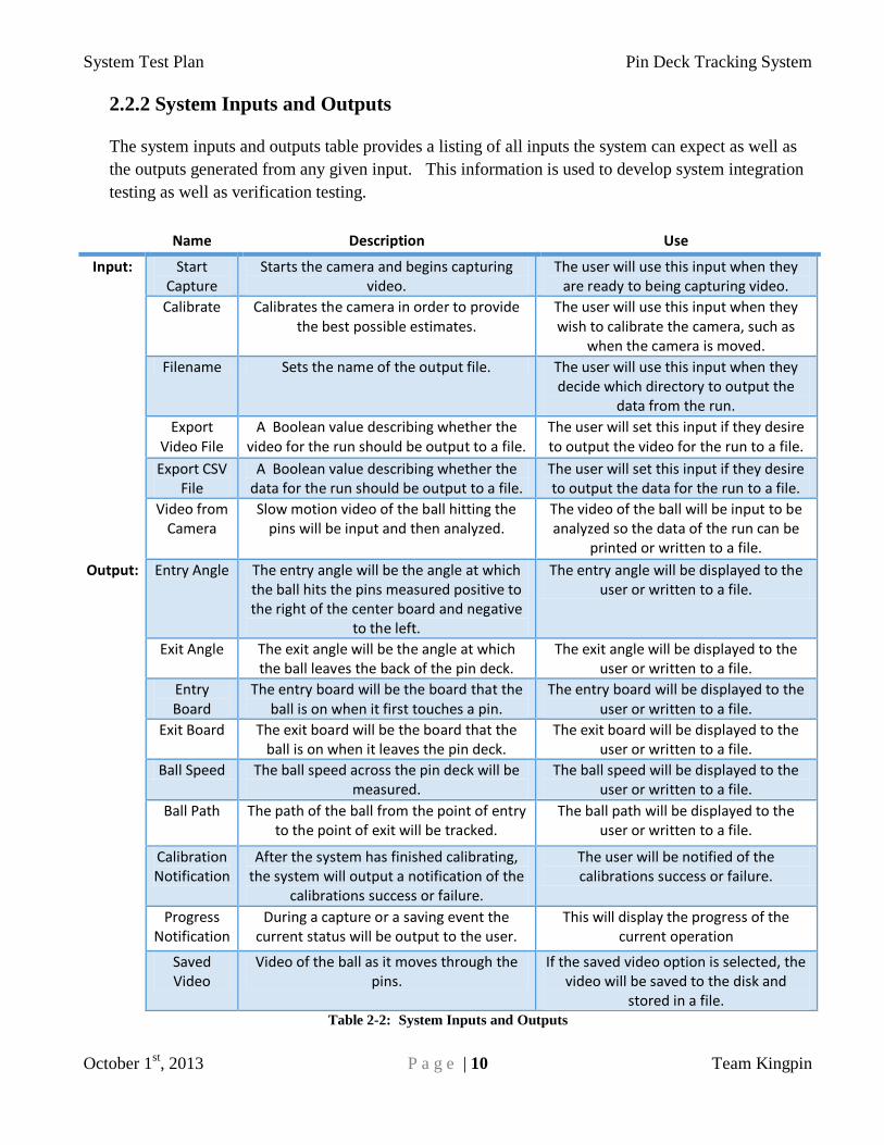
2.2.2 System Inputs and Outputs
The system inputs and outputs table provides a listing of all inputs the system can expect as well as
the outputs generated from any given input. This information is used to develop system integration
testing as well as verification testing.
Table 2-2: System Inputs and Outputs
Name Description Use
Input: Start Capture
Starts the camera and begins capturing video.
The user will use this input when they are ready to being capturing video.
Calibrate Calibrates the camera in order to provide the best possible estimates.
The user will use this input when they wish to calibrate the camera, such as
when the camera is moved.
Filename Sets the name of the output file. The user will use this input when they decide which directory to output the
data from the run.
Export Video File
A Boolean value describing whether the video for the run should be output to a file.
The user will set this input if they desire to output the video for the run to a file.
Export CSV File
A Boolean value describing whether the data for the run should be output to a file.
The user will set this input if they desire to output the data for the run to a file.
Video from Camera
Slow motion video of the ball hitting the pins will be input and then analyzed.
The video of the ball will be input to be analyzed so the data of the run can be
printed or written to a file.
Output: Entry Angle The entry angle will be the angle at which the ball hits the pins measured positive to the right of the center board and negative
to the left.
The entry angle will be displayed to the user or written to a file.
Exit Angle The exit angle will be the angle at which the ball leaves the back of the pin deck.
The exit angle will be displayed to the user or written to a file.
Entry Board
The entry board will be the board that the ball is on when it first touches a pin.
The entry board will be displayed to the user or written to a file.
Exit Board The exit board will be the board that the ball is on when it leaves the pin deck.
The exit board will be displayed to the user or written to a file.
Ball Speed The ball speed across the pin deck will be measured.
The ball speed will be displayed to the user or written to a file.
Ball Path The path of the ball from the point of entry to the point of exit will be tracked.
The ball path will be displayed to the user or written to a file.
Calibration Notification
After the system has finished calibrating, the system will output a notification of the
calibrations success or failure.
The user will be notified of the calibrations success or failure.
Progress Notification
During a capture or a saving event the current status will be output to the user.
This will display the progress of the current operation
Saved Video
Video of the ball as it moves through the pins.
If the saved video option is selected, the video will be saved to the disk and
stored in a file.

System Test Plan Pin Deck Tracking System
October 1st, 2013 P a g e | 11 Team Kingpin
2.3 Architecture Design Specification
2.3.1 Architecture Design Diagram
The Architecture Design Diagram provides a high-level overview of the system layers, the layer
subsystems and the data flows between the layers and subsystems. This information will be used to
develop the component testing of the subsystems as well as the integration testing of each layer.
Image Processing Layer
Detect Motion
Module
Detect Pin
Movement
Module
Image Acquisition Layer
Camera Interface Module Image Preparation Module
Interface Layer
GUI User Interface Controller
File
Camera
User
Control Layer
Event Manager Calibration Manager
File Output Layer
CSV File
Output
Module
Video File I/
O Module
File Output Controller
Locate Ball
Module
Locate Pin Deck
Grid Module
I1
C1
C5
C3 C4
C2
F1 F2
A2
A1
I2I5
I4 C7C6I3
P1
P3
P4
P2
P5 A3
Calibration
I/O Module
F3
Figure 2-1: Architecture Diagram
System Test Plan Pin Deck Tracking System
October 1st, 2013 P a g e | 12 Team Kingpin
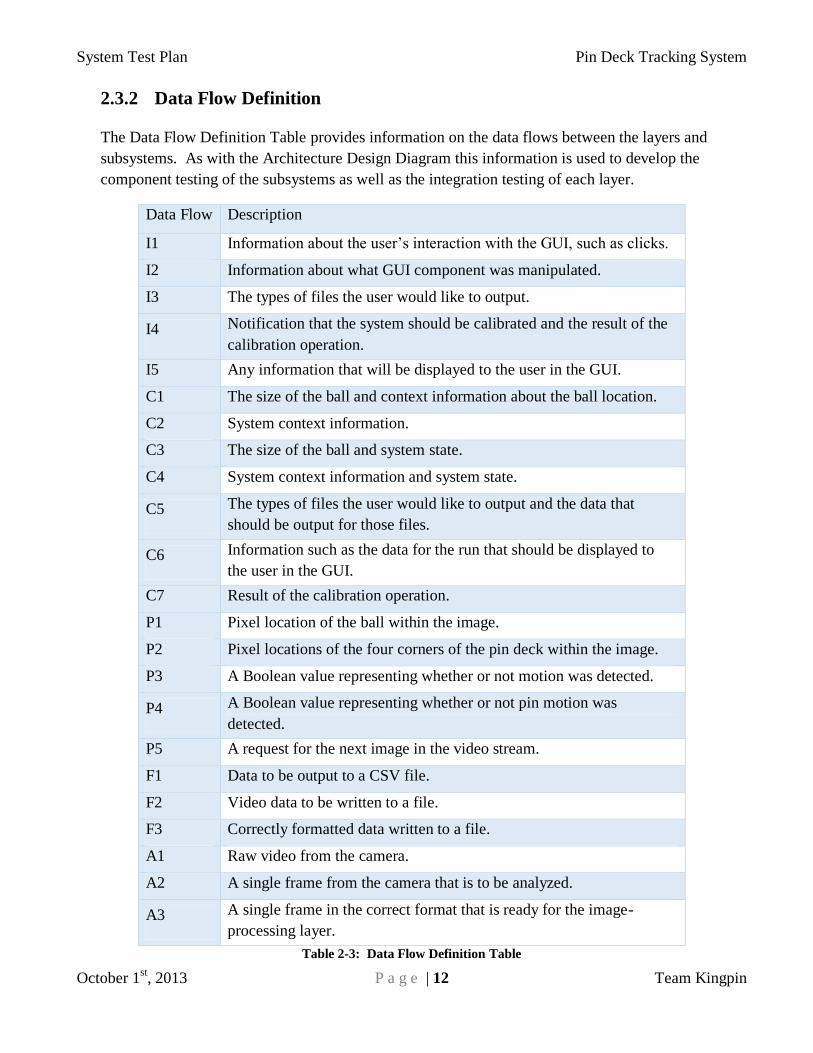
2.3.2 Data Flow Definition
The Data Flow Definition Table provides information on the data flows between the layers and
subsystems. As with the Architecture Design Diagram this information is used to develop the
component testing of the subsystems as well as the integration testing of each layer.
Data Flow Description
I1 Information about the user’s interaction with the GUI, such as clicks.
I2 Information about what GUI component was manipulated.
I3 The types of files the user would like to output.
I4 Notification that the system should be calibrated and the result of the
calibration operation.
I5 Any information that will be displayed to the user in the GUI.
C1 The size of the ball and context information about the ball location.
C2 System context information.
C3 The size of the ball and system state.
C4 System context information and system state.
C5 The types of files the user would like to output and the data that
should be output for those files.
C6 Information such as the data for the run that should be displayed to
the user in the GUI.
C7 Result of the calibration operation.
P1 Pixel location of the ball within the image.
P2 Pixel locations of the four corners of the pin deck within the image.
P3 A Boolean value representing whether or not motion was detected.
P4 A Boolean value representing whether or not pin motion was
detected.
P5 A request for the next image in the video stream.
F1 Data to be output to a CSV file.
F2 Video data to be written to a file.
F3 Correctly formatted data written to a file.
A1 Raw video from the camera.
A2 A single frame from the camera that is to be analyzed.
A3 A single frame in the correct format that is ready for the image-
processing layer.
Table 2-3: Data Flow Definition Table
System Test Plan Pin Deck Tracking System
October 1st, 2013 P a g e | 13 Team Kingpin
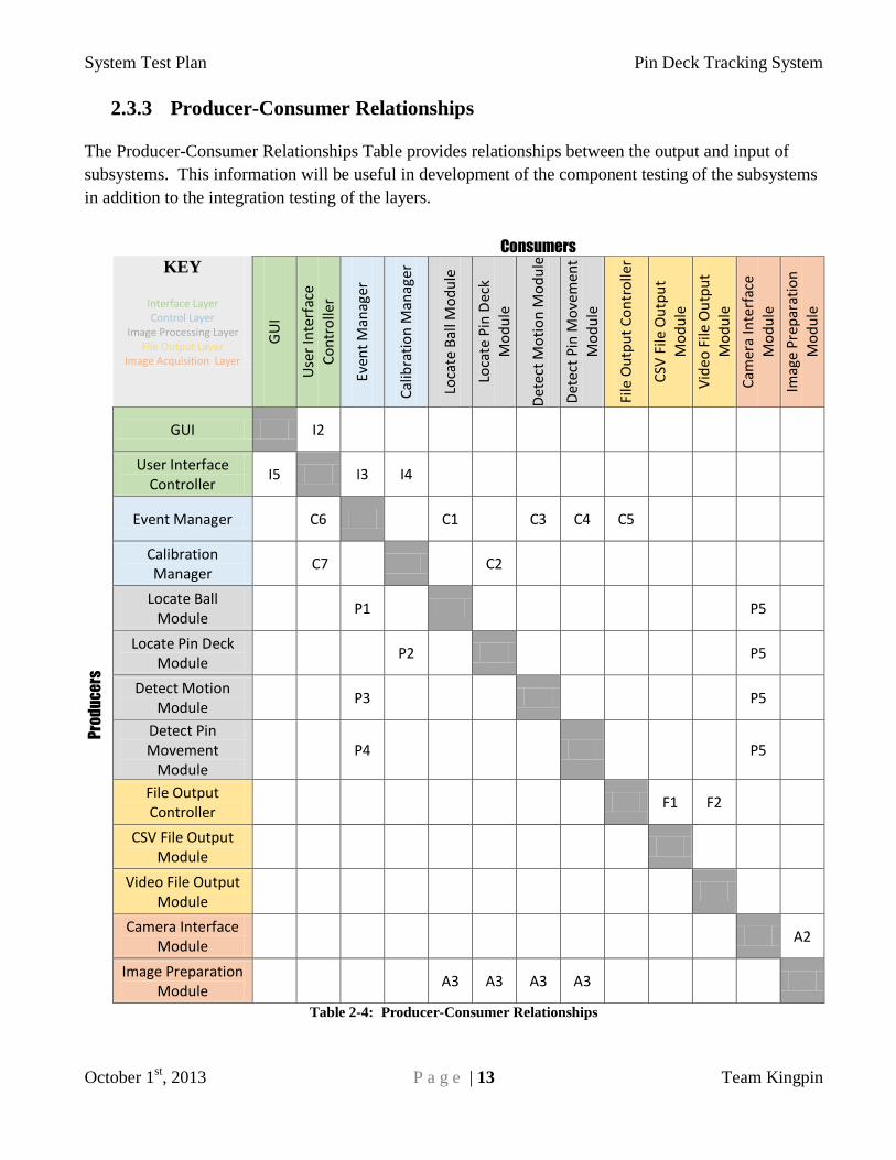
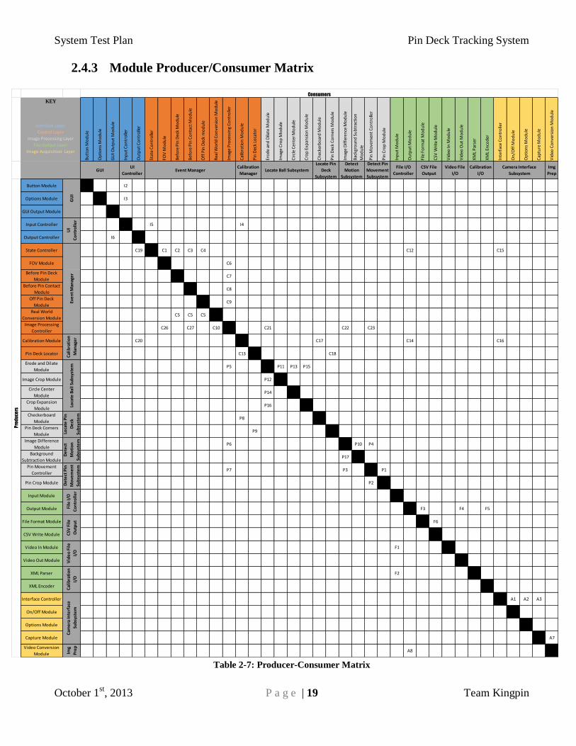
2.3.3 Producer-Consumer Relationships
The Producer-Consumer Relationships Table provides relationships between the output and input of
subsystems. This information will be useful in development of the component testing of the subsystems
in addition to the integration testing of the layers.
Consumers
KEY
Interface Layer Control Layer
Image Processing Layer File Output Layer
Image Acquisition Layer
GU
I
Use
r In
terf
ace
Co
ntr
olle
r
Even
t M
anag
er
Cal
ibra
tio
n M
anag
er
Loca
te B
all M
od
ule
Loca
te P
in D
eck
Mo
du
le
Det
ect
Mo
tio
n M
od
ule
Det
ect
Pin
Mo
vem
ent
Mo
du
le
File
Ou
tpu
t C
on
tro
ller
CSV
File
Ou
tpu
t
Mo
du
le
Vid
eo F
ile O
utp
ut
Mo
du
le
Cam
era
Inte
rfac
e
Mo
du
le
Imag
e P
rep
arat
ion
Mo
du
le
Pro
du
ce
rs
GUI I2
User Interface Controller
I5 I3 I4
Event Manager C6 C1 C3 C4 C5
Calibration Manager
C7 C2
Locate Ball Module
P1 P5
Locate Pin Deck Module
P2 P5
Detect Motion Module
P3 P5
Detect Pin Movement
Module P4 P5
File Output Controller
F1 F2
CSV File Output Module
Video File Output Module
Camera Interface Module
A2
Image Preparation Module
A3 A3 A3 A3
Table 2-4: Producer-Consumer Relationships

System Test Plan Pin Deck Tracking System
October 1st, 2013 P a g e | 14 Team Kingpin
2.3.4 Requirement Mapping
# Name Interface
Layer
Control
Layer
Image
Processing
Layer
File
Output
Layer
Image
Acquisition
Layer
3.1 Entry Board X X X X
3.2 Exit Board X X X X
3.3 Entry Angle X X X X
3.4 Exit Angle X X X X
3.5 Ball Speed X X X
3.6 Ball Path X X
3.7 Pin Movement
3.8 Camera Calibration X X
3.9 Data Output X
5.1 Calibration Performance X X X
5.2 Data Analysis Performance X X
8.3 Team Galaxy Interface
Integration X
8.7 Leftover Pins X X X
Table 2-5: Requirement Mapping
System Test Plan Pin Deck Tracking System
October 1st, 2013 P a g e | 15 Team Kingpin
2.3.5 Layer Data Descriptions
2.3.4.1 Interface Layer
The interface layer will receive data from the end user through the user’s interaction with the
GUI. The GUI will have clickable buttons, check boxes, and radio buttons allowing user to
manipulate the system. The user interface controller will then take actions in response to
manipulations of the GUI by the user. Depending upon the input type, the user interface
controller will send the information to either the event manager or the calibration manager of the
control layer. The user interface controller also receives responses back from control layer,
which will be displayed to the user via the GUI.
2.3.4.2 Control Layer
The control layer will receive information from the interface layer about which type of output the
user has selected. The control layer then sends this information to the file output layer. The
control layer will be receiving information from the image-processing layer. The calibration
manager will receive the four corners of the pin deck from the image-processing layer. The
event manager will receive information about ball motion, pin motion, or the location of the ball
depending on the state of the system.
2.3.4.3 Image Processing Layer
The image-processing layer will receive an image from the image acquisition layer upon request.
2.3.4.4 File I/O Layer
The file output layer will receive information from the event manger subsystem of the control
layer. The control layer will send the file type information and other data such as the ball
position, speed, angle, entry board, and exit board to file output controller subsystem of the file
output layer. Depending upon user’s choice of output file types, the file output controller will
send the data to either CSV file output module or video file output module. Then, the file output
module will save the data to the disk.
2.3.4.5 Image Acquisition Layer
The image acquisition layer will receive raw images from camera and prepares images to feed
into image processing layer. First camera interface module will receive raw images from camera
and those captured images will be sent to image preparation module. Image preparation module
will determine if raw images need to be preprocessed or formatted. After images are formatted
and preprocessed as required, the image preparation subsystem will send images to image
processing layer.

System Test Plan Pin Deck Tracking System
October 1st, 2013 P a g e | 16 Team Kingpin
2.4 Detailed Design Specification
2.4.1 Detailed Design Diagram
The Detailed Design Diagram provides an overall view of the system modules.
Pin Deck Tracking System
Interface Layer
GUI User Interface Controller
Button Module Options Module GUI Output Module Input Controller Output Controller
I1
I2 I3
I6
Control Layer
Event Manager
Calibration Manager
State Controller
FOV Module Before Pin Deck ModuleBefore Pin Contact
ModuleOff Pin Deck Module
Real World ConversionModule
Image Processing Controller
Calibration Module (TIMER) Pin Deck Locator
User
I5
I4
C19
C20
File I/O LayerImage Processing Layer
Image Acquisition Layer
Input Module Output Module
File I/O Controller
CSV File Output Video File I/O Calibration I/O
File Format Module
CSV Write Module
Video In Module
Video Out Module
XML Parser
XML Encoder
Locate Ball Subsystem Locate Pin Deck Subsystem
Detect Motion Subsystem Detect Pin Movement Subsystem
Erode and Dilate Module
Image Crop
Module
Crop Expansion
Module
Circle Center Module
Checkerboard Module
Pin Deck Corners Module
Image Difference Module
Background Subtraction Module
Pin Movement Controller
Pin Crop Module
Camera Interface Subsystem Image Preparation Subsystem
Interface Contoller
On/Off ModuleOptions Module
Capture Module
Video Conversion ModuleA1A2
A3
A4 A5 A6
Camera
A7
A8
F4
F8
File
F1
F11F7
F6
F3F5
F2
F9F10
C15
C9C8C7C6 C10
C3C2C1
C16 C13
C18
C17
C14
C12
C5
C4
C21 C22 C23
C25
P1
P3
P4
C24
C11
P8
P9
P5
P6
P7
P2P10
C26 C27
P11
P14
Display
P12 P13
Figure 2-2: Detailed Architecture Diagram

System Test Plan Pin Deck Tracking System
October 1st, 2013 P a g e | 17 Team Kingpin
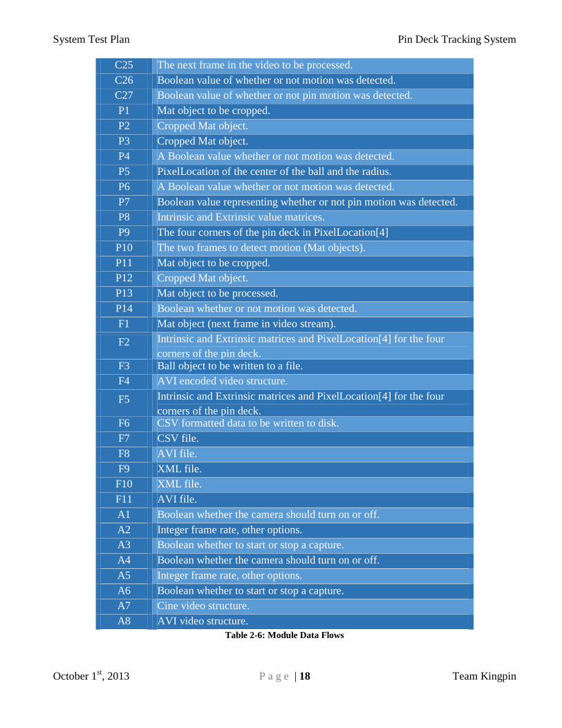
2.4.2 Module Data Flows
The module data flows chart provides a description for every data flow between each module within
the system. This information is used to develop all system testing.
Data Flow Description
I1 User clicks/interactions with the GUI.
I2 Unsigned integer ID of button clicked.
I3 Unsigned integer ID of checkbox clicked.
I4 Request for calibration
I5 Array of Booleans for each option in the GUI.
I6 String to update GUI.
C1 Next frame in the video stream (Mat object).
C2 Next frame in the video stream (Mat object).
C3 Next frame in the video stream (Mat object).
C4 Next frame in the video stream (Mat object).
C5 Location (Real World) structure.
C6 Mat objects (2) to be processed.
C7 Mat object to be processed.
C8 Mat object to be processed.
C9 Mat object to be processed.
C10 PixelLocation (Pixel) structure.
C11 Intrinsic and Extrinsic value matrices and an array of
PixelLocation[4] representing the four corners of the pin deck.
C12 Ball object to be output to a file and array of Booleans for the type of
files to output.
C13 Location[4] representing the four corners of the pin deck in the real
world.
C14 Intrinsic and Extrinsic value matrices and an array of
PixelLocation[4] representing the four corners of the pin deck.
C15 Boolean of whether to start capturing video or stop capturing video.
C16 Boolean of whether to start capturing video or stop capturing video.
C17 Mat object to be processed.
C18 Mat object to be processed
C19 Ball object to be output to the GUI.
C20 Result of calibration unsigned integer.
C21 Mat object to be processed.
C22 Mat objects (2) to be processed
C23 Mat objects (2) to be processed
C24 The next frame in the video to be processed.
System Test Plan Pin Deck Tracking System
October 1st, 2013 P a g e | 18 Team Kingpin
C25 The next frame in the video to be processed.
C26 Boolean value of whether or not motion was detected.
C27 Boolean value of whether or not pin motion was detected.
P1 Mat object to be cropped.
P2 Cropped Mat object.
P3 Cropped Mat object.
P4 A Boolean value whether or not motion was detected.
P5 PixelLocation of the center of the ball and the radius.
P6 A Boolean value whether or not motion was detected.
P7 Boolean value representing whether or not pin motion was detected.
P8 Intrinsic and Extrinsic value matrices.
P9 The four corners of the pin deck in PixelLocation[4]
P10 The two frames to detect motion (Mat objects).
P11 Mat object to be cropped.
P12 Cropped Mat object.
P13 Mat object to be processed.
P14 Boolean whether or not motion was detected.
F1 Mat object (next frame in video stream).
F2 Intrinsic and Extrinsic matrices and PixelLocation[4] for the four
corners of the pin deck. F3 Ball object to be written to a file.
F4 AVI encoded video structure.
F5 Intrinsic and Extrinsic matrices and PixelLocation[4] for the four
corners of the pin deck. F6 CSV formatted data to be written to disk.
F7 CSV file.
F8 AVI file.
F9 XML file.
F10 XML file.
F11 AVI file.
A1 Boolean whether the camera should turn on or off.
A2 Integer frame rate, other options.
A3 Boolean whether to start or stop a capture.
A4 Boolean whether the camera should turn on or off.
A5 Integer frame rate, other options.
A6 Boolean whether to start or stop a capture.
A7 Cine video structure.
A8 AVI video structure.
Table 2-6: Module Data Flows
System Test Plan Pin Deck Tracking System
October 1st, 2013 P a g e | 19 Team Kingpin
2.4.3 Module Producer/Consumer Matrix
Table 2-7: Producer-Consumer Matrix
Bu
tto
n M
od
ule
Op
tio
ns
Mo
du
le
GU
I Ou
tpu
t M
od
ule
Inp
ut
Co
ntr
olle
r
Ou
tpu
t C
on
tro
ller
Stat
e C
on
tro
ller
FOV
Mo
du
le
Bef
ore
Pin
Dec
k M
od
ule
Bef
ore
Pin
Co
nta
ct M
od
ule
Off
Pin
Dec
k m
od
ule
Rea
l Wo
rld
Co
nve
rsio
n M
od
ule
Imag
e P
roce
ssin
g C
on
tro
ller
Cal
ibra
tio
n M
od
ule
Pin
Dec
k Lo
cato
r
Ero
de
and
Dila
te M
od
ule
Imag
e C
rop
Mo
du
le
Cir
cle
Cen
ter
Mo
du
le
Cro
p E
xpan
sio
n M
od
ule
Ch
ecke
rbo
ard
Mo
du
le
Pin
Dec
k C
orn
ers
Mo
du
le
Imag
e D
iffe
ren
ce M
od
ule
Bac
kgro
un
d S
ub
trac
tio
n
Mo
du
le
Pin
Mo
vem
ent
Co
ntr
olle
r
Pin
Cro
p M
od
ule
Inp
ut
Mo
du
le
Ou
tpu
t M
od
ule
File
Fo
rmat
Mo
du
le
CSV
Wri
te M
od
ule
Vid
eo In
Mo
du
le
Vid
eo O
ut
Mo
du
le
XM
L P
arse
r
XM
L En
cod
er
Inte
rfac
e C
on
tro
ller
On
/Off
Mo
du
le
Op
tio
ns
Mo
du
le
Cap
ture
Mo
du
le
Vid
eo C
on
vers
ion
Mo
du
le
Img
Prep
Button Module I2
Options Module I3
GUI Output Module
Input Controller I5 I4
Output Controller I6
State Controller C19 C1 C2 C3 C4 C12 C15
FOV Module C6
Before Pin Deck
ModuleC7
Before Pin Contact
ModuleC8
Off Pin Deck
ModuleC9
Real World
Conversion ModuleC5 C5 C5
Image Processing
ControllerC26 C27 C10 C21 C22 C23
Calibration Module C20 C17 C14 C16
Pin Deck Locator C13 C18
Erode and Dilate
ModuleP5 P11 P13 P15
Image Crop Module P12
Circle Center
ModuleP14
Crop Expansion
ModuleP16
Checkerboard
ModuleP8
Pin Deck Corners
ModuleP9
Image Difference
ModuleP6 P10 P4
Background
Subtraction ModuleP17
Pin Movement
ControllerP7 P3 P1
Pin Crop Module P2
Input Module
Output Module F3 F4 F5
File Format Module F6
CSV Write Module
Video In Module F1
Video Out Module
XML Parser F2
XML Encoder
Interface Controller A1 A2 A3
On/Off Module
Options Module
Capture Module A7
Video Conversion
Module Img
Pre
p
A8
Cal
ibra
tio
n
Man
age
r
Calibration
Manager
Loca
te B
all S
ub
syst
em
Loca
te P
in
De
ck
Sub
syst
em
Pro
du
ce
rs
KEY
Interface Layer
Control Layer
Image Processing Layer
File Output Layer
Image Acquisition Layer
GUIUI
Controller
GU
IU
I
Co
ntr
oll
er
Eve
nt
Man
age
r
De
tect
Mo
tio
n
Sub
syst
em
De
tect
Pin
Mo
vem
en
t
Sub
syst
em
Consumers
Video File
I/O
Calibration
I/O
Cam
era
Inte
rfac
e
Sub
syst
em
Camera Interface
Subsystem
Locate Pin
Deck
Subsystem
Detect
Motion
Subsystem
Detect Pin
Movement
Subsystem
File I/O
Controller
CSV File
Output
File
I/O
Co
ntr
oll
er
CSV
Fil
e
Ou
tpu
t
Vid
eo
Fil
e
I/O
Cal
ibra
tio
n
I/O
Locate Ball SubsystemEvent Manager

System Test Plan Pin Deck Tracking System
October 1st, 2013 P a g e | 20 Team Kingpin
3. Test Items
3.1 Overview
This section will provide detail covering the five phase testing plan needed to ensure the creation of a
successful project. The following relational Diagram (Figure 3.1) represents the five testing phases in a
flowchart layout. The five phases are as follows; hardware testing, unit testing, component testing,
integration testing, and system verification. The layout of this test plan allows us to show that once
everything in a phase is complete, the data received from the modules in that phase can be reasonably
assumed correct. This allows us to focus almost completely on the tests on our current phase.
3.2 Relational Diagram
Figure 3-1 Relational Diagram
System Test Plan Pin Deck Tracking System
October 1st, 2013 P a g e | 21 Team Kingpin
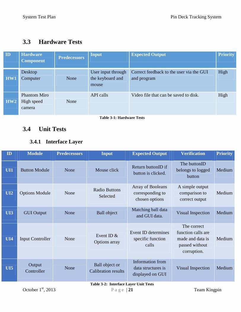
3.3 Hardware Tests
ID Hardware
Component Predecessors
Input Expected Output Priority
HW1
Desktop
Computer None
User input through
the keyboard and
mouse
Correct feedback to the user via the GUI
and program
High
HW2
Phantom Miro
High speed
camera
None
API calls Video file that can be saved to disk. High
Table 3-1: Hardware Tests
3.4 Unit Tests
3.4.1 Interface Layer
ID Module Predecessors Input Expected Output Verification Priority
UI1 Button Module None Mouse click Return buttonID if
button is clicked.
The buttonID
belongs to logged
button
Medium
UI2 Options Module None Radio Buttons
Selected
Array of Booleans
corresponding to
chosen options
A simple output
comparison to
correct output
Medium
UI3 GUI Output None Ball object Matching ball data
and GUI data. Visual Inspection Medium
UI4 Input Controller None Event ID &
Options array
Event ID determines
specific function
calls
The correct
function calls are
made and data is
passed without
corruption.
Medium
UI5 Output
Controller None
Ball object or
Calibration results
Information from
data structures is
displayed on GUI
Visual Inspection Medium
Table 3-2: Interface Layer Unit Tests

System Test Plan Pin Deck Tracking System
October 1st, 2013 P a g e | 22 Team Kingpin
3.4.2 Control Layer
ID Module Predecessors Input Expected Output Verification Priority
UC1 State Controller
None
Image with trigger
or Ball Object
Same Image or Ball
Object in the correct
“state” i.e. the next
in succession
State conditions
must be logged and
checked after a run
High
UC2 FOV
None
Mat Object Boolean value of
motion detected or
not detected.
Assert with
expected results
High
UC3 Before Pin
Deck None
Mat Object & Ball
Location
Ball Location as ball
enters Pin deck.
Assert with
expected results
High
UC4 Before Pin
Contact None
Mat Object & Ball
Location
Bool flag for contact
detected &
collection of Mat
Objects
Manual verification High
UC5 Off Pin Deck None
Mat Object & Ball
Location
Bool flag for Off Pin
Deck detected
Assert with
expected results
High
UC6 Real World
Conversion None
Pixel Location &
Calibration
Matrices
Real World Location Assert with
expected results
High
UC7 Image
Processing None
Mat Objects &
Pixel Locations
Mat Objects & Pixel
Locations and None
correct function calls
Assert with
expected results
Medium
UC8 Calibration
None
Calibration
Matrices, Request
for calibration
Calibration matrices
and pixel locations
of deck corners
Real world values
would be measured
against the results
High
UC9 Pin Deck
Locator None
Mat Object, Pixel
Locations
Four coordinate
points representing
the corners of the
pin deck
Manual comparison
between pre-
computed and
current run.
High
Table 3-3: Control Layer Unit Tests

System Test Plan Pin Deck Tracking System
October 1st, 2013 P a g e | 23 Team Kingpin
3.4.3 Image Processing Layer
ID Module Predecessors Input Expected Output Verification Priority
UC1 Erode & Dilate None Mat Object Processed Mat
Object
Manual inspection
to ensure proper
filters applied
High
UC2 Image Crop None Mat Object Processed Mat
Object
Manual Inspection
to ensure proper
crop applied
High
UC3 Circle center None Mat Object Pixel Location Manual Inspection High
UC4 Crop
Expansion None Mat Object
Expands area
around location of
the previous Images
ball location
Manual Inspection
that ball is within
the cropped region
High
UC5 Checkerboard None Mat Object Calibrated matrices
values to be written
to disk
Manual verification
based on previous
good inputs
High
UC6 Pin Deck
Corners None Mat Object
Vector of 4 pixel
locations at which
the corners are
located
Manual
verification. Verify
against known
readings
High
UC7 Image
Difference None Mat Objects[2]
Bool value
indicating
movement
Assert with
expected results High
UC8 Background
Subtraction None Mat Objects[2]
Bool value
indicating
movement
Assert with
exposed result High
UC9 Pin Movement
Controller None
Mat Objects[2],
motion flag Cropped Mat Object
Manual verification
through visual
inspection
Low
UC10 Pin Crop
Module None Mat Objects[2] Cropped Mat Object
Manual
Verification
through visual
inspection
Low
Table 3-4: Image Processing Layer Unit Tests
System Test Plan Pin Deck Tracking System
October 1st, 2013 P a g e | 24 Team Kingpin
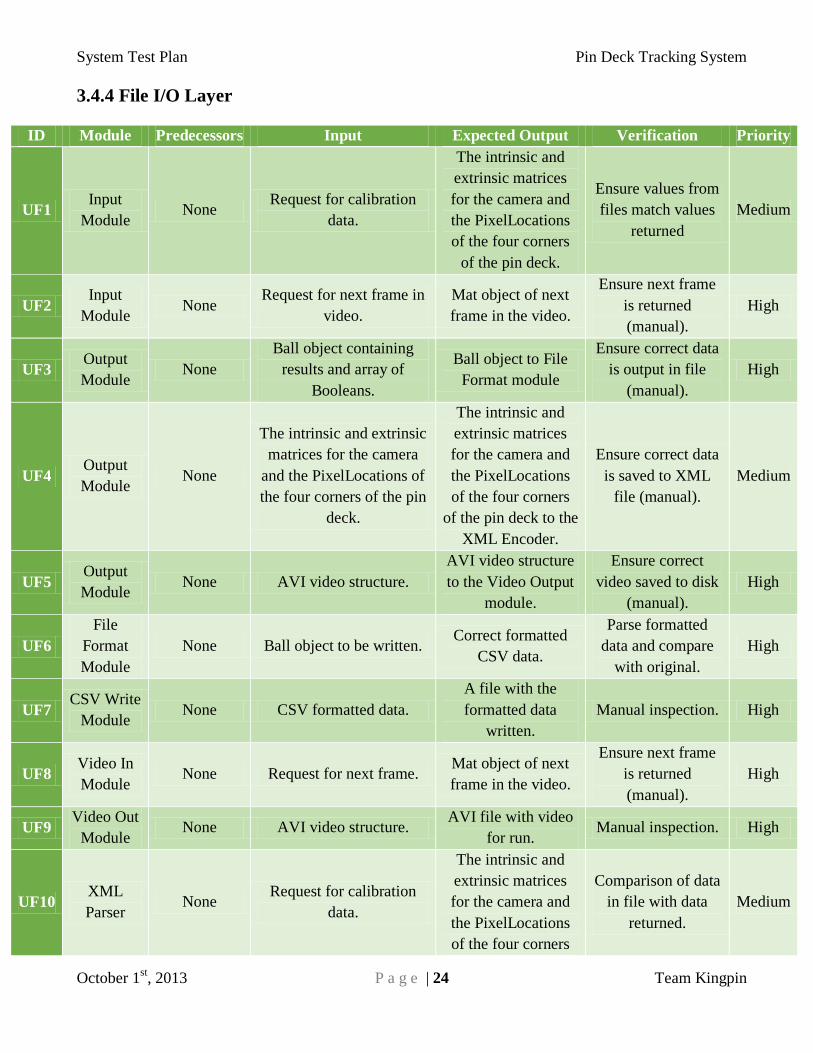
3.4.4 File I/O Layer
ID Module Predecessors Input Expected Output Verification Priority
UF1 Input
Module None
Request for calibration
data.
The intrinsic and
extrinsic matrices
for the camera and
the PixelLocations
of the four corners
of the pin deck.
Ensure values from
files match values
returned
Medium
UF2 Input
Module None
Request for next frame in
video.
Mat object of next
frame in the video.
Ensure next frame
is returned
(manual).
High
UF3 Output
Module None
Ball object containing
results and array of
Booleans.
Ball object to File
Format module
Ensure correct data
is output in file
(manual).
High
UF4 Output
Module None
The intrinsic and extrinsic
matrices for the camera
and the PixelLocations of
the four corners of the pin
deck.
The intrinsic and
extrinsic matrices
for the camera and
the PixelLocations
of the four corners
of the pin deck to the
XML Encoder.
Ensure correct data
is saved to XML
file (manual).
Medium
UF5 Output
Module None AVI video structure.
AVI video structure
to the Video Output
module.
Ensure correct
video saved to disk
(manual).
High
UF6
File
Format
Module
None Ball object to be written. Correct formatted
CSV data.
Parse formatted
data and compare
with original.
High
UF7 CSV Write
Module None CSV formatted data.
A file with the
formatted data
written.
Manual inspection. High
UF8 Video In
Module None Request for next frame.
Mat object of next
frame in the video.
Ensure next frame
is returned
(manual).
High
UF9 Video Out
Module None AVI video structure.
AVI file with video
for run. Manual inspection. High
UF10 XML
Parser None
Request for calibration
data.
The intrinsic and
extrinsic matrices
for the camera and
the PixelLocations
of the four corners
Comparison of data
in file with data
returned.
Medium

System Test Plan Pin Deck Tracking System
October 1st, 2013 P a g e | 25 Team Kingpin
of the pin deck.
UF11 XML
Encoder None
The intrinsic and extrinsic
matrices for the camera
and the PixelLocations of
the four corners of the pin
deck.
XML endcoded data
file. Manual inspection. Medium
Table 3-5: File I/O Layer Unit Tests
3.4.5 Image Acquisition Layer
ID Module Predecessor
s Input Expected Output Verification Priority
UA1 Interface
Controller None
Boolean
representing to start
capturing video or to
stop.
The camera should turn
on and begin capturing
video if the Boolean is
true or turn off and stop
if it is false.
Ensure a video is
saved when a true
Boolean is passed
first and later is
passed a false.
High
UA2 On/Off
Module None
Boolean whether to
turn the camera
on/off.
The camera should turn
on if the Boolean is ture
or off otherwise.
Ensure the camera is
on when a true
Boolean is passed
and off otherwise.
High
UA3 Options
Module None
Request to initialize
camera options.
Hard coded values sent
to camera.
After a video is
saved ensure that the
video has the correct
FPS and other
options.
Low
UA4 Capture
Module None Requests for the
capture to start.
The camera should
begin to capture video.
First request the
camera to start
capturing and later
to stop. Then verify
the video began at
the correct time.
Medium
UA5 Capture
Module None CINE video
structure
Full CINE encoded
video.
Ensure video
conversion module
receives full video
by manual
inspection.
High
UA6
Video
Conversion
Module
None CINE video
structure Full AVI encoded video
Play back saved AVI
to ensure correct
encoding of video.
High
Table 3-6: Image Acquisition Layer Unit Tests
System Test Plan Pin Deck Tracking System
October 1st, 2013 P a g e | 26 Team Kingpin
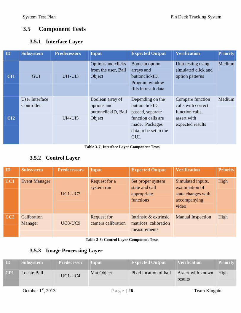
3.5 Component Tests
3.5.1 Interface Layer
ID Subsystem Predecessors Input Expected Output Verification Priority
CI1 GUI UI1-UI3
Options and clicks
from the user, Ball
Object
Boolean option
arrays and
buttonclickID.
Program window
fills in result data
Unit testing using
simulated click and
option patterns
Medium
CI2
User Interface
Controller
UI4-UI5
Boolean array of
options and
buttonclickID, Ball
Object
Depending on the
buttonclickID
passed, separate
function calls are
made. Packages
data to be set to the
GUI.
Compare function
calls with correct
function calls,
assert with
expected results
Medium
Table 3-7: Interface Layer Component Tests
3.5.2 Control Layer
ID Subsystem Predecessors Input Expected Output Verification Priority
CC1 Event Manager
UC1-UC7
Request for a
system run
Set proper system
state and call
appropriate
functions
Simulated inputs,
examination of
state changes with
accompanying
video
High
CC2 Calibration
Manager UC8-UC9
Request for
camera calibration
Intrinsic & extrinsic
matrices, calibration
measurements
Manual Inspection High
Table 3-8: Control Layer Component Tests
3.5.3 Image Processing Layer
ID Subsystem Predecessor Input Expected Output Verification Priority
CP1 Locate Ball UC1-UC4
Mat Object Pixel location of ball Assert with known
results
High
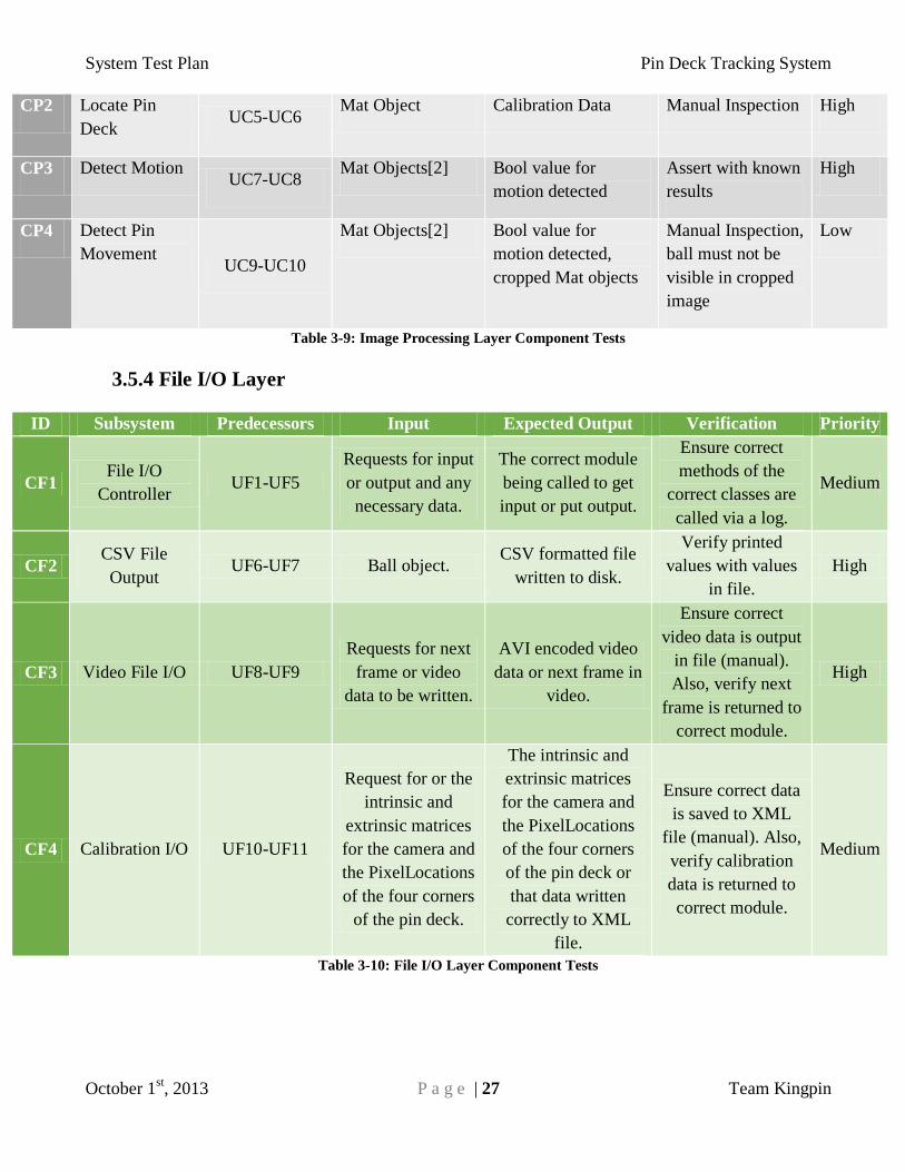
System Test Plan Pin Deck Tracking System
October 1st, 2013 P a g e | 27 Team Kingpin
CP2 Locate Pin
Deck UC5-UC6
Mat Object Calibration Data Manual Inspection High
CP3 Detect Motion UC7-UC8
Mat Objects[2] Bool value for
motion detected
Assert with known
results
High
CP4 Detect Pin
Movement UC9-UC10
Mat Objects[2] Bool value for
motion detected,
cropped Mat objects
Manual Inspection,
ball must not be
visible in cropped
image
Low
Table 3-9: Image Processing Layer Component Tests
3.5.4 File I/O Layer
ID Subsystem Predecessors Input Expected Output Verification Priority
CF1 File I/O
Controller UF1-UF5
Requests for input
or output and any
necessary data.
The correct module
being called to get
input or put output.
Ensure correct
methods of the
correct classes are
called via a log.
Medium
CF2 CSV File
Output UF6-UF7 Ball object.
CSV formatted file
written to disk.
Verify printed
values with values
in file.
High
CF3 Video File I/O UF8-UF9
Requests for next
frame or video
data to be written.
AVI encoded video
data or next frame in
video.
Ensure correct
video data is output
in file (manual).
Also, verify next
frame is returned to
correct module.
High
CF4 Calibration I/O UF10-UF11
Request for or the
intrinsic and
extrinsic matrices
for the camera and
the PixelLocations
of the four corners
of the pin deck.
The intrinsic and
extrinsic matrices
for the camera and
the PixelLocations
of the four corners
of the pin deck or
that data written
correctly to XML
file.
Ensure correct data
is saved to XML
file (manual). Also,
verify calibration
data is returned to
correct module.
Medium
Table 3-10: File I/O Layer Component Tests

System Test Plan Pin Deck Tracking System
October 1st, 2013 P a g e | 28 Team Kingpin
3.5.5 Image Acquisition Layer
ID Module Predecessors Input Expected Output Verification Priority
CA1
Camera
Interface
Subsystem
UA1-UA5
Boolean
representing to
start capturing
video or to stop.
Full encoded CINE
video.
Manual playback of
video after being
saved.
High
CA2
Camera
Interface
Subsystem
UA1-UA5 CINE video
structure
Full encoded CINE
video structure.
Manual playback of
video after being
saved.
High
CA3
Image
Preparation
Subsystem
UA6 CINE video
structure
Full AVI encoded
video structure.
Ensure the video
output module gets
video data by
verifying the
correct video is
written to a file.
High
Table 3-11: Image Acquisition Layer Component Tests
3.6 Integration Tests
3.6.1 Interface Layer
ID Input Predecessor Expected Output Verification Priority
II1 User
interactions with
the GUI.
CI1
Operations
chosen by user to
be executed.
Log the user interactions and compare with
action system took.
High
II2 Results from
calibration or
system run
CI2
Results to be
displayed to user.
Ensure correct data appears on GUI by
manual inspection.
High
Table 3-12: Interface Layer Integration Tests
3.6.2 Control Layer
ID Input Predecessor Expected Output Verification Priority
IC1 Array of
Booleans of
which files to
output.
CC1
Files with data
from run
Log the user interactions and compare with
action system that was taken.
High
IC2 Results from
calibration or
system run
CC2
Results to be
displayed to user.
Ensure correct data appears on GUI by
manual inspection.
High
Table 3-13: Control Layer Integration Tests
System Test Plan Pin Deck Tracking System
October 1st, 2013 P a g e | 29 Team Kingpin
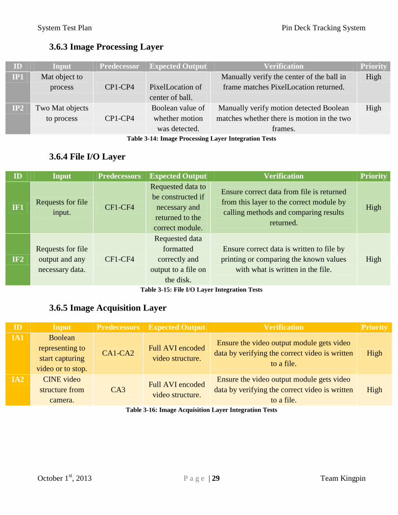
3.6.3 Image Processing Layer
ID Input Predecessor Expected Output Verification Priority
IP1 Mat object to
process CP1-CP4
PixelLocation of
center of ball.
Manually verify the center of the ball in
frame matches PixelLocation returned.
High
IP2 Two Mat objects
to process CP1-CP4
Boolean value of
whether motion
was detected.
Manually verify motion detected Boolean
matches whether there is motion in the two
frames.
High
Table 3-14: Image Processing Layer Integration Tests
3.6.4 File I/O Layer
ID Input Predecessors Expected Output Verification Priority
IF1 Requests for file
input. CF1-CF4
Requested data to
be constructed if
necessary and
returned to the
correct module.
Ensure correct data from file is returned
from this layer to the correct module by
calling methods and comparing results
returned.
High
IF2
Requests for file
output and any
necessary data.
CF1-CF4
Requested data
formatted
correctly and
output to a file on
the disk.
Ensure correct data is written to file by
printing or comparing the known values
with what is written in the file.
High
Table 3-15: File I/O Layer Integration Tests
3.6.5 Image Acquisition Layer
ID Input Predecessors Expected Output Verification Priority
IA1 Boolean
representing to
start capturing
video or to stop.
CA1-CA2 Full AVI encoded
video structure.
Ensure the video output module gets video
data by verifying the correct video is written
to a file.
High
IA2 CINE video
structure from
camera.
CA3 Full AVI encoded
video structure.
Ensure the video output module gets video
data by verifying the correct video is written
to a file.
High
Table 3-16: Image Acquisition Layer Integration Tests

System Test Plan Pin Deck Tracking System
October 1st, 2013 P a g e | 30 Team Kingpin
3.7 System Verification Tests
ID Requirement Predecessor Input Expected Output Verification Priority
SV1 Entry Board All integration
tests
System will be run
for one video
capture of the ball
across the pin
deck.
The board at which
the ball first contacts
the pin is correctly
output to the file and
displayed to the
user.
Manually verify
entry board
matches calculated
entry board.
Critical
SV2 Exit Board All integration
tests
System will be run
for one video
capture of the ball
across the pin
deck.
The board at which
the ball first leaves
the pin is correctly
output to the file and
displayed to the
user.
Manually verify
exit board matches
calculated exit
board.
Critical
SV3 Entry Angle All integration
tests
System will be run
for one video
capture of the ball
across the pin
deck.
The angle at which
the ball travels when
it first contacts the
pins is correctly
output to the file and
the user.
Manually verify
entry angle
correlates with
calculated entry
angle.
Critical
SV4 Exit Angle All integration
tests
System will be run
for one video
capture of the ball
across the pin
deck.
The angle at which
the ball travels when
it first leaves the pin
deck is correctly
output to the file and
the user.
Manually verify
exit angle correlates
with calculated exit
angle.
Critical
SV4 Ball Path All integration
tests
System will be run
for one video
capture of the ball
across the pin
deck.
The correct path of
the ball across the
pin deck displayed
to user.
Manually verify
position for each
point in the ball
path correlates with
calculated position.
Medium
SV5 Ball Speed All integration
tests
System will be run
for one video
capture of the ball
across the pin
deck.
The average speed
of the ball across the
pin deck is output to
the user.
Manually calculate
the average speed
and verify it
correlates with the
systems calculated
value.
Medium
SV7 Calibration All integration
tests
System will take a
series of images of
an empty pin deck.
The intrinsic and
extrinsic matrices
for the camera and
the PixelLocations
Manually verify the
matrices with a
known camera
position
Critical

System Test Plan Pin Deck Tracking System
October 1st, 2013 P a g e | 31 Team Kingpin
of the four corners
of the pin deck or
that data written
correctly to XML
file.
SV8 System
Performance
All integration
tests
System will be run
for one video
capture of the ball
across the pin
deck.
The data for a run
within a reasonable
amount of time.
Time the run time
of the system. Medium
SV9 Data Output All integration
tests
System will be run
for one video
capture of the ball
across the pin
deck.
The correct data for
a run of the system
output to a file.
Manually verify the
file is output as a
comma separated
value file.
Critical
Table 3-17: System Verification Tests
System Test Plan Pin Deck Tracking System
October 1st, 2013 P a g e | 32 Team Kingpin
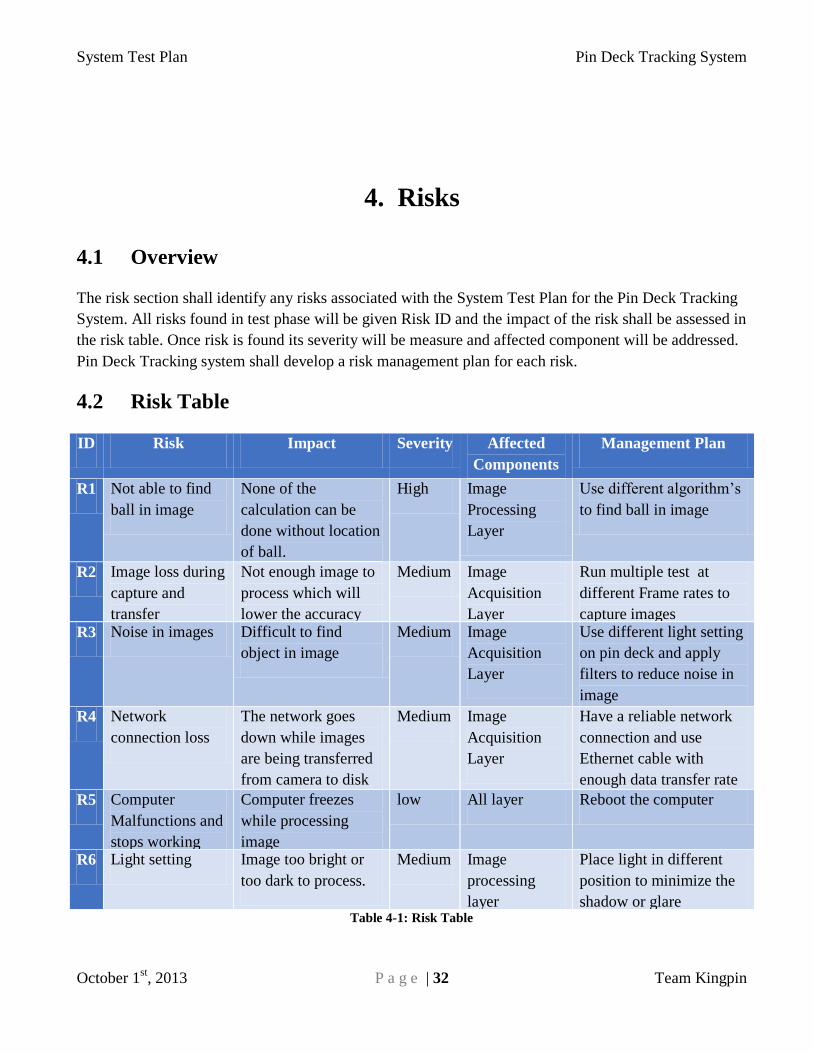
4. Risks
4.1 Overview
The risk section shall identify any risks associated with the System Test Plan for the Pin Deck Tracking
System. All risks found in test phase will be given Risk ID and the impact of the risk shall be assessed in
the risk table. Once risk is found its severity will be measure and affected component will be addressed.
Pin Deck Tracking system shall develop a risk management plan for each risk.
4.2 Risk Table
ID Risk Impact Severity Affected
Components
Management Plan
R1 Not able to find
ball in image
None of the
calculation can be
done without location
of ball.
High Image
Processing
Layer
Use different algorithm’s
to find ball in image
R2 Image loss during
capture and
transfer
Not enough image to
process which will
lower the accuracy
Medium Image
Acquisition
Layer
Run multiple test at
different Frame rates to
capture images R3 Noise in images Difficult to find
object in image
Medium Image
Acquisition
Layer
Use different light setting
on pin deck and apply
filters to reduce noise in
image
R4 Network
connection loss
The network goes
down while images
are being transferred
from camera to disk
Medium Image
Acquisition
Layer
Have a reliable network
connection and use
Ethernet cable with
enough data transfer rate
R5 Computer
Malfunctions and
stops working
Computer freezes
while processing
image
low All layer Reboot the computer
R6 Light setting Image too bright or
too dark to process.
Medium Image
processing
layer
Place light in different
position to minimize the
shadow or glare Table 4-1: Risk Table
System Test Plan Pin Deck Tracking System
October 1st, 2013 P a g e | 33 Team Kingpin
5. Testable Features
5.1 Overview
This section includes the list of customer requirement in SRS. These features can be tested and verified
by the users as well as by team King Pin. Features listed in this section are to be thoroughly tested to
ensure all the requirements are satisfied.
Following are the levels of risks associated with each test
• High: Feature may be difficult to test
• Medium: Has been tested and may not work as expected
• Low: Will be implemented and work properly
5.2 Customer Requirements
5.2.1 Entry Board
5.2.1.1 Risk
Medium
5.2.1.2 Description
This test will verify whether the board number the ball is on just before the ball strikes
the first pin is accurate to half the width of a single board.
5.2.1.3 Test Approach
This test shall manually verify if entry board number produced by Pin Deck tracking
system matches the calculated.
5.2.2 Exit Board
5.2.2.1 Risk
Medium
System Test Plan Pin Deck Tracking System
October 1st, 2013 P a g e | 34 Team Kingpin
5.2.2.2 Description
This test will verify whether the board number the ball is on just before the ball leaves the
pin deck is accurate to half the width of a single board.
5.2.2.3 Test Approach
This test shall manually verify if exit board number produced by Pin Deck tracking
system matches the calculated.
5.2.3 Entry Angle
5.2.3.1 Risk
High
5.2.3.2 Description
This test shall verify the entry angle of the ball just before the ball strikes the first pin
with accuracy of angle within + - 1.0 degree.
5.2.3.3 Test Approach
This test shall manually verify entry angle with calculated entry angle.
5.2.4 Exit Angle
5.2.4.1 Risk
High
5.2.4.2 Description
This test shall verify the exit angle of the ball just before the ball just before the ball falls
off the pin deck with accuracy of angle within + - 1.0 degree.
5.2.4.3 Test Approach
This test shall manually verify exit angle with calculated exit angle.
5.2.5 Ball Speed
5.2.5.1 Risk
High
System Test Plan Pin Deck Tracking System
October 1st, 2013 P a g e | 35 Team Kingpin
5.2.5.2 Description
This test shall verify whether the speed of the bowling ball at a given position on the pin
deck is within accuracy of 0.01 mph.
5.2.5.3 Test Approach
This test will manually calculate the average speed and verify it correlates with the
systems calculated value.
5.2.6 Ball Path
5.2.6.1 Risk
High
5.2.6.2 Description
This test shall verify whether the position of the ball for every frame located on the pin
deck is within accuracy of ¼ of an inch.
5.2.6.3 Test Approach
This test shall manually verify position for each point in the ball path correlates with
calculated position.
5.2.7 Pin Movement
5.2.7.1 Risk
High
5.2.7.2 Description
This test shall verify the position of each pin while the ball is still on the pin deck
represented by a pair of (x,y,z) coordinates.
5.2.7.3 Test Approach
This test shall manually verify the position of each pin with calculated position of each
pin while the ball is still on the pin deck.
5.2.8 Camera Calibration
5.2.8.1 Risk
High

System Test Plan Pin Deck Tracking System
October 1st, 2013 P a g e | 36 Team Kingpin
5.2.8.2 Description
This test shall verify whether the camera is properly calibrated or not.
5.2.8.3 Test Approach
This test shall be manually verified the matrices with a known camera position.
5.2.9 Data Output
5.2.9.1 Risk
Low
5.2.9.2 Description
This test shall verify whether the output data from system is accurately written in a
comma separated value file and saved is specified location in disk.
5.2.9.3 Test Approach
Output file shall be located in specified folder in disk and data in comma separated value
shall be testified against the expected result.
5.3 Packaging Requirements
5.3.1 System Hardware Assembly
5.3.1.1 Risk
Low
5.3.1.2 Description
This test shall verify whether all the hardware components like camera, Ethernet cable,
system computer are assembled as required by the pin deck tracking system.
5.3.1.3 Test Approach
The System computer shall be powered and we shall run the camera calibration test
program to make sure camera captures specified number of frame and saves to specified
location of system computer.
5.3.2 Software Delivery
5.3.2.1 Risk
Low

System Test Plan Pin Deck Tracking System
October 1st, 2013 P a g e | 37 Team Kingpin
5.3.2.2 Description
This test shall verify whether the system software is properly transferred to a memory
stick with required library files, source file, and APIs.
5.3.2.3 Test Approach
Memory stick with Pin deck tracking system software shall be inserted in three other
computers with different configurations and we shall check manually whether all
required source file, library files and APIs has been copied or not.
5.3.3 Software Installation
5.3.2.1 Risk
Low
5.3.3.2 Description
This test shall verify whether the system software is properly installs in the system
computer or not.
5.3.3.3 Test Approach
Memory stick with Pin deck tracking system software shall be inserted in system
computer and install the software. Team leader shall verify whether software is properly
installed or not by running the dummy test programs. Then software is uninstalled. This
process is repeated 3 times to make sure software installs without any errors.
5.3.4 User Manual
5.3.1.1 Risk
Low
5.3.1.2 Description
This test shall verify whether the user manual is copied in memory stick or not.
5.3.1.3 Test Approach
Memory stick with Pin deck tracking system software shall be inserted in system
computer Team leader shall verify manually whether User Manual is copied or not.

System Test Plan Pin Deck Tracking System
October 1st, 2013 P a g e | 38 Team Kingpin
5.4 Performance Requirements
5.4.1 Calibration Performance
5.4.1.1 Risk
Low
5.4.1.2 Description
This test shall verify whether the system’s calibration module shall complete in an
acceptable time frame.
5.4.1.3 Test Approach
The Pin Deck Tracking System software shall be run in system computer. Calibration
button and stop watch shall be pressed together and time taken to perform calibration
shall be recorded. Above process shall be run five times and average time is calculated.
Then we will check if average time for calibration falls under acceptable time frame.
5.4.2 Data Analysis Performance
5.4.2.1 Risk
Low
5.4.2.2 Description
This test shall verify whether the systems data analysis module shall process images in an
acceptable time frame.
5.4.2.3 Test Approach
The Pin Deck Tracking System software shall be run in the system computer. Start
Capture button and stop watch shall be pressed together and time taken to perform Data
Analysis shall be recorded. Above process shall be run five times and average time is
calculated. Then we will check if average time for Data Analysis falls under acceptable
time frame

System Test Plan Pin Deck Tracking System
October 1st, 2013 P a g e | 39 Team Kingpin
6. Non-Testable Features
6.1 Overview
The following features listed are not to be tested since they are verified by system design. These
features describe the system properties of the product and do not much functionality. Some features are
tested and verified by USBC.
6.2 Safety Requirements
6.2.1 Camera Mounting
The camera shall be mounted away from moving machine parts and in such a way that no harm or
damage is caused to the camera by surrounding machinery, pin movement or ball movement.
6.2.2 Lighting Mounting
Lighting shall be mounted so that it will not obstruct the functionality of any other device or
machinery in the pin deck area creating opportunity for hardware damage.
6.2.3 Cabling / wiring
Cables and wires must be laid in a way to prevent the obstruction of the bowling lane, pin deck and
any area trafficked by the user.
6.2.4 User Safety
The system shall be built in a way to prevent the need of the user to interact with the system during
the capture and analysis process to prevent harm to the user from moving machinery.
6.3 Maintenance and Support Requirements
6.3.1 Source Code
Team Kingpin’s source code shall be well documented with comments and details to allow future
teams to modify functionality, troubleshooting procedures, maintenance procedures, or upgrade the
system.
System Test Plan Pin Deck Tracking System
October 1st, 2013 P a g e | 40 Team Kingpin
6.3.2 Troubleshooting Instructions
Team Kingpin shall provide documentation to assist in troubleshooting activities in the event that
the system does not operate properly.
6.3.3 System Maintenance
Team Kingpin shall not provide maintenance to the system or source code after delivery of the
system to the customer.
6.3.4 Training
USBC personal shall be trained to use the Pin Deck Tracking System. They shall be trained to setup
the system, interface with camera, exporting the data, and troubleshoot the system
6.4 Other Requirements
6.4.1Windows OS Support
6.4.1.1 Description
The software Team Kingpin develops for the sponsor must be compatible with the
Windows OS.
6.4.2 Code Modularity
6.4.2.1 Description
The code developed by Team Kingpin shall be modular in nature in order to support the
extension of our code in possible future projects.
6.4.3 Team Galaxy Interface Integration
6.4.3.1 Description
Team Kingpin shall integrate the system’s graphical user interface with Team Galaxy’s
graphical user interface.
System Test Plan Pin Deck Tracking System
October 1st, 2013 P a g e | 41 Team Kingpin
7. Testing Approach/Strategy
7.1 Overview
This section outline the strategy that Team Kingpin will use to test the Pin Deck Tracking
System. The tests designed and executed to ensure that the Pin Deck Tracking System meets the
requirements set in the System Requirement Specification. The tests are designed for all aspects
of the system, both hardware and software.
7.2 Overall Test Strategy
Team Kingpin will write component and unit tests, where applicable, for each module in the
system. The person whom developed the component or module will be responsible for writing
these tests. In addition, Team Kingpin will perform integration testing and system verification.
Integration testing will be a more collaborative effort than the unit and component tests. The
team members responsible developing a part of a subsystem will collaborate to design and
execute integration tests. Finally, the whole team will take part in designing procedures for
system verification.
7.3 Methodology
Unit tests will be written after the completion of a module. In general, unit tests will attempt to
test all boundary cases in addition to normal cases. The unit tests written must be passed before
the team member submits the module as complete. Component tests will, in addition to testing
modules, ensure the interfaces and interactions among modules are functioning correctly.
Component tests will be performed once two or more modules which interact have passed unit
testing. For both unit and component tests, there will be some tests which cannot be automated.
In these cases the team will perform these tests manually. After unit and component testing has
been completed on modules of a subsystem, the subsystems will undergo integration testing.
Integration testing will ensure the validity of the interfaces and interactions between other
subsystems that have passed unit and component tests. Finally, the system will undergo system
verification in which the team will ensure all requirements defined in the System Requirements
Specification are met.

System Test Plan Pin Deck Tracking System
October 1st, 2013 P a g e | 42 Team Kingpin
7.4 Testing Metrics
The test cases designed by Team Kingpin will have an associated priority which will represent
the importance of the test passing. The importance will be decided by the team based on its
relation to the requirements and the nature of the component being tested. The priorities for the
tests cases are defined as follows:
7.4.1 Critical
These tests must be successful for the system to be accepted.
7.4.2 High
Failure of these tests will greatly affect the system’s functionality.
7.4.3 Medium
Failure of these tests are not critical, but will reduce functionality of the system.
7.4.4 Low
Failure of these tests indicate small functionality deficiencies.
7.5 Testing Requirements
Automatic tests will be written using Microsoft’s testing tools. However, automatic tests will not
always be available. For example, verifying that the ball location in pixels is correct will require
a manual inspection of the image. In the cases that tests cannot be done automatically, the tests
will be sufficiently documented in order to ensure that they are performed consistently.

System Test Plan Pin Deck Tracking System
October 1st, 2013 P a g e | 43 Team Kingpin
8. Item Pass/Fail Criteria
8.1 Overview
The Pass/Fail criteria describes how a test is determined to pass or fail for each test type. These
types of tests are: hardware, unit, component, integration, and system verification. Each type of
test has its own unique criteria for passing and failing as defined below.
8.2 Hardware Tests
8.2.1 Pass
The hardware component produces the expected output for a given valid input. An error or
exception is generated by the hardware component for a given invalid input.
8.2.2 Fail
The hardware component produces unexpected output for a given valid input. An error or
exception is not generated by the hardware component for a given invalid input.
8.3 Unit Tests
8.3.1 Pass
The module produces an expected output for a given valid input. An error or exception is
generated by the module for a given invalid input.
8.3.2 Fail
The module produces an unexpected output for a given valid input. An error or exception is not
generated by the module for a given invalid input.
8.4 Component Tests
8.4.1 Pass
A subsystem produces an expected output for all valid inputs from another subsystem. It also
produces an error or exception for all the invalid inputs from another subsystem.
8.4.2 Fail
A subsystem produces an unexpected output for any valid inputs from another subsystem. Or, it
produces an error or exception for any valid inputs from another subsystem.
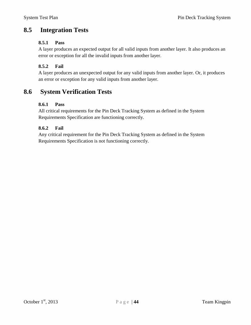
System Test Plan Pin Deck Tracking System
October 1st, 2013 P a g e | 44 Team Kingpin
8.5 Integration Tests
8.5.1 Pass
A layer produces an expected output for all valid inputs from another layer. It also produces an
error or exception for all the invalid inputs from another layer.
8.5.2 Fail
A layer produces an unexpected output for any valid inputs from another layer. Or, it produces
an error or exception for any valid inputs from another layer.
8.6 System Verification Tests
8.6.1 Pass
All critical requirements for the Pin Deck Tracking System as defined in the System
Requirements Specification are functioning correctly.
8.6.2 Fail
Any critical requirement for the Pin Deck Tracking System as defined in the System
Requirements Specification is not functioning correctly.

System Test Plan Pin Deck Tracking System
October 1st, 2013 P a g e | 45 Team Kingpin
9. Test Deliverables
9.1 Overview
Team Kingpin will deliver all code, documentation, and results for all of the test cases run,
including unit, component, integration and system verification tests. These items shall be
delivered with the product either as a physical copy or as soft copy included on the USB memory
stick which holds the Pin Deck Tracking System software.
9.2 Deliverables
9.2.1 System Test Plan
This document which outlines Team Kingpin’s plan for testing the Pin Deck Tracking
System shall be included in the delivery to the customer.
9.2.2 Test Cases
The test cases designed by Team Kingpin shall be included in the delivery to the
customer. Each test case will include the following data:
Test Case Name
Test Case Description
Test Case Priority
Input
Expected Output
Pass/Fail Result
Additional Comments
Tester’s Name
9.2.3 Test Results
The results of all tests shall be included in the delivery to the customer. The results for
each test will be represented as either a pass or a fail.
9.2.4 Automated Test Code
The code for all tests which were performed automatically shall be included in the
delivery to the customer. This will include any code written for unit, component, and
integration testing.
System Test Plan Pin Deck Tracking System
October 1st, 2013 P a g e | 46 Team Kingpin
9.2.4 Known Bugs
Any known bugs in the system that are known to Team Kingpin at the time of product
delivery shall be included in the delivery to the customer. Each bug report shall include
the following:
Test Case Name
Test Case Description
Status (Fixed/Fail)
Severity
Input
Expected Output
Comments on bug effects.
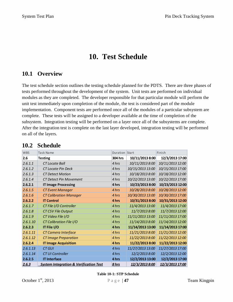
System Test Plan Pin Deck Tracking System
October 1st, 2013 P a g e | 47 Team Kingpin
10. Test Schedule
10.1 Overview
The test schedule section outlines the testing schedule planned for the PDTS. There are three phases of
tests performed throughout the development of the system. Unit tests are performed on individual
modules as they are completed. The developer responsible for that particular module will perform the
unit test immediately upon completion of the module, the test is considered part of the module
implementation. Component tests are performed once all of the modules of a particular subsystem are
complete. These tests will be assigned to a developer available at the time of completion of the
subsystem. Integration testing will be performed on a layer once all of the subsystems are complete.
After the integration test is complete on the last layer developed, integration testing will be performed
on all of the layers.
10.2 Schedule
Table 10-1: STP Schedule
WBS Task Name Duration Start Finish
2.6 Testing 304 hrs 10/11/2013 8:00 12/3/2013 17:00
2.6.1.1 CT Locate Ball 4 hrs 10/11/2013 8:00 10/11/2013 12:00
2.6.1.2 CT Locate Pin Deck 4 hrs 10/15/2013 13:00 10/15/2013 17:00
2.6.1.3 CT Detect Motion 4 hrs 10/18/2013 8:00 10/18/2013 12:00
2.6.1.4 CT Detect Pin Movement 4 hrs 10/22/2013 13:00 10/22/2013 17:00
2.6.2.1 IT Image Processing 4 hrs 10/23/2013 8:00 10/23/2013 12:00
2.6.1.5 CT Event Manager 4 hrs 10/28/2013 8:00 10/28/2013 12:00
2.6.1.6 CT Calibration Manager 4 hrs 10/30/2013 13:00 10/30/2013 17:00
2.6.2.2 IT Control 4 hrs 10/31/2013 8:00 10/31/2013 12:00
2.6.1.7 CT File I/O Controller 4 hrs 11/4/2013 13:00 11/4/2013 17:00
2.6.1.8 CT CSV File Output 4 hrs 11/7/2013 8:00 11/7/2013 12:00
2.6.1.9 CT Video File I/O 4 hrs 11/11/2013 13:00 11/11/2013 17:00
2.6.1.10 CT Calibration File I/O 4 hrs 11/14/2013 8:00 11/14/2013 12:00
2.6.2.3 IT File I/O 4 hrs 11/14/2013 13:00 11/14/2013 17:00
2.6.1.11 CT Camera Interface 4 hrs 11/21/2013 8:00 11/21/2013 12:00
2.6.1.12 CT Image Preparation 4 hrs 11/22/2013 8:00 11/22/2013 12:00
2.6.2.4 IT Image Acquisition 4 hrs 11/22/2013 8:00 11/22/2013 12:00
2.6.1.13 CT GUI 4 hrs 11/27/2013 13:00 11/27/2013 17:00
2.6.1.14 CT UI Controller 4 hrs 12/2/2013 8:00 12/2/2013 12:00
2.6.2.5 IT Interface 4 hrs 12/2/2013 13:00 12/2/2013 17:00
2.6.3 System Integration & Verification Test 8 hrs 12/3/2013 8:00 12/3/2013 17:00
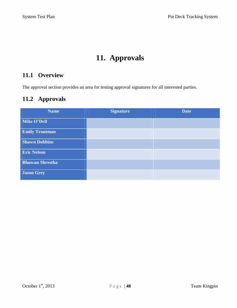
System Test Plan Pin Deck Tracking System
October 1st, 2013 P a g e | 48 Team Kingpin
11. Approvals
11.1 Overview
The approval section provides an area for testing approval signatures for all interested parties.
11.2 Approvals
Name Signature Date
Mike O’Dell
Emily Troutman
Shawn Dobbins
Eric Nelson
Bhuwan Shrestha
Jason Grey