dental service and chair parts manual - midmark medical ... · for use by midmark trained...
TRANSCRIPT
FOR USE BY MIDMARKTRAINED TECHNICIANS ONLY
Service andParts Manual
SF-1606 Part No. 004-0252-00 (12/29/2016)
Serial Number Prefixes:CP, PB & V
Biltmore Classic
Concept L/R Classic
DentalChair
Biltmore Clas.Concept L/RClassic
NOTE:Sterling Grey painted parts are no longer available. Check manual and use Pebble Grey painted parts if available.


TABLE OF CONTENTS
© Midmark Corporation 1999 SF-1606 Page i Printed in U.S.A.
IMPORTANT INSTRUCTIONSGeneral Safety Instructions ......................................... iiiSafety Alert Symbols ................................................... iiiWarranty Instructions ................................................. iii
SECTION I GENERAL INFORMATION1.1 Scope of Manual .......................................... 1-11.2 How to Use Manual ...................................... 1-11.3 Description Of Chair ..................................... 1-11.4 Standard Torque Specifications.................... 1-61.5 Specifications ............................................... 1-61.6 Parts Replacement Ordering........................ 1-81.7 Special Tools ................................................ 1-8
SECTION II TESTING AND TROUBLESHOOTING2.1 Operational Test (See Figure 2-1) ................ 2-12.2 Troubleshooting Procedures......................... 2-4
SECTION III SCHEDULED MAINTENANCE3.1 Scheduled Maintenance ............................. 3-1
SECTION IV MAINTENANCE/SERVICEINSTRUCTIONS
4.1 Introduction................................................... 4-14.2 Upholstery
Removal .................................................... 4-1Installation ................................................. 4-1
4.3 Base CapacitorRemoval .................................................... 4-2Installation ................................................. 4-2
4.4 Base Motor Removal .................................................... 4-3Installation ................................................. 4-6
4.5 Base Motor Worm GearRemoval .................................................... 4-8Installation ................................................. 4-8
4.6 Base Motor TrunnionRemoval .................................................... 4-9Disassembly.............................................. 4-9Assembly................................................... 4-9Installation ................................................. 4-9
4.7 Back MotorRemoval .................................................. 4-10Installation ............................................... 4-11
4.8 Back Motor CapacitorRemoval .................................................. 4-13Installation ............................................... 4-13
4.9 P.C. BoardRemoval .................................................. 4-14Installation ............................................... 4-14
4.10 Base Up & Base Down Limit SwitchesRemoval.................................................. 4-15Installation............................................... 4-15Adjustment.............................................. 4-15
4.11 Base Up Program Limit SwitchRemoval.................................................. 4-17Installation............................................... 4-17
4.12 Back Up Limit SwitchRemoval.................................................. 4-18Installation............................................... 4-18Adjustment.............................................. 4-18
4.13 Back Down Program Limit SwitchRemoval.................................................. 4-19Installation............................................... 4-19Adjustment.............................................. 4-19
4.14 Safety Bail Limit SwitchesRemoval.................................................. 4-20Installation............................................... 4-21
4.15 Membrane Switch PanelRemoval.................................................. 4-22Installation............................................... 4-22
4.16 Manual FootswitchRemoval.................................................. 4-22Installation............................................... 4-22
4.17 Auto Exit / Operate FootswitchRemoval.................................................. 4-23Installation............................................... 4-23
4.18 Rotational BrakeRemoval.................................................. 4-24Installation............................................... 4-24Adjustment.............................................. 4-25
4.19 HeadrestAdjustment.............................................. 4-26
SECTION V SCHEMATICS AND DIAGRAMS5.1 Electrical Schematics /
Wiring Diagrams ..................................... 5-1
SECTION VI PARTS LIST6.1 Introduction ................................................ 6-16.2 Description Of Columns ............................... 6-16.3 Torque Specifications And Important
Assembly Notes........................................ 6-1Pictorial Index [Sterling Grey]....................... 6-2Pictorial Index [Pebble Grey]........................ 6-3Upholstery Components (Vacuum Form)[Sterling Grey] .............................................. 6-4Upholstery Components (Vacuum Form)[Pebble Grey] ............................................... 6-5
TABLE OF CONTENTS
(*) Indicates that there has been a serial number break for the illustrationand that there are additional point page(s) following the original page.
Rev. 3/03
Section/Paragraph................................................Page Section/Paragraph ............................................... Page
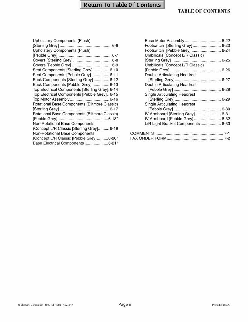
TABLE OF CONTENTS
© Midmark Corporation 1999 SF-1606 Page ii Printed in U.S.A.
Upholstery Components (Plush)[Sterling Grey] .............................................. 6-6Upholstery Components (Plush)[Pebble Grey]................................................ 6-7Covers [Sterling Grey] .................................. 6-8Covers [Pebble Grey] ................................... 6-9Seat Components [Sterling Grey]............... 6-10Seat Components [Pebble Grey] ................ 6-11Back Components [Sterling Grey] .............. 6-12Back Components [Pebble Grey] ............... 6-13Top Electrical Components [Sterling Grey]. 6-14Top Electrical Components [Pebble Grey] .. 6-15Top Motor Assembly................................... 6-16Rotational Base Components (Biltmore Classic)[Sterling Grey] ............................................ 6-17Rotational Base Components (Biltmore Classic)[Pebble Grey].............................................6-18*Non-Rotational Base Components (Concept L/R Classic [Sterling Grey].......... 6-19Non-Rotational Base Components (Concept L/R Classic [Pebble Grey] ..........6-20*Base Electrical Components .....................6-21*
Base Motor Assembly ................................ 6-22Footswitch [Sterling Grey] ......................... 6-23Footswitch [Pebble Grey] .......................... 6-24Umbilicals (Concept L/R Classic)[Sterling Grey] ............................................ 6-25Umbilicals (Concept L/R Classic) [Pebble Grey] ............................................. 6-26Double Articulating Headrest
[Sterling Grey]......................................... 6-27Double Articulating Headrest
[Pebble Grey] .......................................... 6-28Single Articulating Headrest
[Sterling Grey]......................................... 6-29Single Articulating Headrest
[Pebble Grey] .......................................... 6-30IV Armboard [Sterling Grey]....................... 6-31IV Armboard [Pebble Grey] ........................ 6-32L/R Light Bracket Components .................. 6-33
COMMENTS ............................................................. 7-1FAX ORDER FORM.................................................. 7-2
Rev. 5/10

TABLE OF CONTENTS
© Midmark Corporation 1999 SF-1606 Page iii Printed in U.S.A.
General Safety Instructions
Safety First: The primary concern of Midmark Cor-poration is that this chair is maintained with the safety of the patient and staff in mind. To assure that services and repairs are completed safely and correctly, proceed as follows:
(1) Read this entire manual before performing any services or repairs on this chair.
(2) Be sure you understand instructions contained in this manual before attempting to service or repair chair.
Safety Alert Symbols
Throughout this manual are safety alert symbols that call attention to particular procedures. These items are used as follows:
Warranty Instructions
Refer to Midmark “Limited Warranty” printed in the Installation and Operation Manual for warranty informa-tion. Failure to follow guidelines listed below will void the warranty and/or render the Biltmore Classic or Con-cept L/R Dental Chair unsafe for operation.
• In event of a malfunction, do not attempt to use dental chair until necessary repairs have been made.
• Do not attempt to disassemble chair, replace mal-functioning or damaged components, or perform adjustments unless you are one of Midmark’s authorized service technicians.
• Do not substitute parts of another manufacturer when replacing inoperative or damaged compo-nents. Use only Midmark replacement parts.DANGER
A DANGER is used for an imminently hazardous operating procedure, prac-
tice, or condition which, if not correctly followed, will result in loss of life or serious personal injury.
WARNINGA WARNING is used for a potentially hazardous operating procedure, prac-
tice, or condition which, if not correctly followed, could result in loss of life or serious personal injury.
CAUTIONA CAUTION is used for a potentially haz-ardous operating procedure, practice, or
condition which, if not correctly followed, could result in minor or moderate injury. It may also be used to alert against unsafe practices.
EQUIPMENT ALERTAn EQUIPMENT ALERT is used for an imminently or potentially hazardous oper-
ating procedure, practice, or condition which, if not correctly followed, will or could result in serious, mod-erate, or minor damage to unit.
NOTEA NOTE is used to amplify an operating procedure, practice or condition.
Rev. 3/03


SECTION IGENERAL INFORMATION
© Midmark Corporation 1999 SF-1606 Page 1-1 Printed in U.S.A.
1.1 Scope of Manual
This manual contains detailed troubleshooting, sched-uled maintenance, maintenance, and service instruc-tions for the Biltmore Classic and the Concept L/R Dental Chair. This manual is intended to be used by Midmark’s authorized service technicians.
1.2 How to Use Manual
A. Manual Use When Performing Scheduled Mainte-nance.
(1) Perform inspections and services listed in Scheduled Maintenance Chart (Refer to para 3.1).
(2) If a component is discovered to be faulty or out of adjustment, replace or adjust component in accordance with maintenance / service instruc-tions (Refer to para 4.1).
B. Manual Use When Unit Is Malfunctioning And Cause Is Unknown.
(1) Perform an operational test on chair (Refer to para 2.1).
(2) Perform troubleshooting procedures listed in Troubleshooting Guide (Refer to para 2.2).
(3) If a component is discovered to be faulty or out of adjustment, replace or adjust component in accordance with maintenance / service instruc-tions (Refer to para 4.1).
C. Manual Use When Damaged Component Is Known.
(1) Replace or adjust component in accordance with maintenance / service instructions (Refer to para 4.1).
1.3 Description Of Dental Chair
A. General Description (See Figure 1-1).
The Biltmore Classic and the Concept L/R Chair are dental operating chairs designed for the general den-tistry market. Positions of Chair are adjustable thru use of electromechanical motors. The operator can initiate movement using one of two chair mounted membrane touch pads (Biltmore Classic only), the foot control or the optional hand control (Concept L/R only).
B. Major Serviceable Components (See Figure 1-1).
Membrane Touch Pads (Biltmore Classic only) (1, Figure 1-1)
A membrane touch pad assembly is located on both sides of the chairback to allow operation of chair from either side. The Automatic Operate / Exit switches (A) are predetermined program settings and actuated by depressing and releasing the appropriate switch. The functions can be stopped by momentarily depressing any switch on the touch pads or foot control. Back Up, Back Down, Base Up, and Base Down switches (B) must be depressed and held until desired position is achieved.
Headrest Locking Assembly (2, Figure 1-1)
Headrest height can be changed by pulling out or push-ing in on headrest. Tension of headrest locking assem-bly is pre-set at factory but can be adjusted if required (Refer to para 4.19).
Base Motor & Capacitor (3, Figure 1-1)
Base Motor controls the vertical movement of the chair by a cantilevered action up 13” (33 cm) while moving forward 4.5” (11.4 cm). Directional windings allow the motor to run forward or backward depending on which way power is applied to the windings. Base motor uses a run capacitor, located on the mounting plate next to the P.C. Board, to provide start and run power. The motor is for intermittent operation. Continuous operation will cause motor to overheat, causing internal thermal overload to open, removing power from the motor. Normal cool off period for thermal overload to reset to closed position is 10 to 20 minutes.
SECTION IGENERAL INFORMATION
Rev. 3/03

SECTION IGENERAL INFORMATION
© Midmark Corporation 1999 SF-1606 Page 1-2 Printed in U.S.A.
Figure 1-1. Component Location

SECTION IGENERAL INFORMATION
© Midmark Corporation 1999 SF-1606 Page 1-3 Printed in U.S.A.
Back Motor & Capacitor (4, Figure 1-1)
Back Motor controls the movement of the chairback from a seated position (upright) to a reclined position (supine). The directional windings allow the motor to run forward or backward.Back Motor uses a run capacitor, mounted on the motor, to provide start and run power. Two Internal limit switches in motor prevent it from reaching its mechanical limits, damaging the motor. The normally closed (N.C.) limit switches are factory set and should not require any adjustments.The motor is for intermittent operation. Continuous operation will cause the motor to overheat, activating the internal thermal overload, removing power from the motor. Normal cool off period for the thermal overload to reset is 10 to 20 minutes.
P.C. Board w/ Fuses (5, Figure 1-1)
The P.C. Board contains plug connectors, 12 VDC sup-ply transformer for control circuitry, base and back motor control relays, 10 amp line (115 VAC) input motor fuse, 1/2 amp fuse for low voltage (12 VDC) circuitry. Spare fuses (C) are located to the left of each opera-tional fuse.
Back Up Limit Switch (6, Figure 1-1)
Back Up Limit Switch is a normally closed (N.C.) switch, located on the seat frame of patient’s left side. It con-trols the amount Back section moves upright, to a seated position, from reclined (supine) position. As Back section moves upright, seat section is also moving inward. When the spacer, located on patient’s left side seat support, contacts the switch actuator on Back Up Limit Switch it causes N.C. contacts to open, removing power from Back Motor.
Back Down Program Limit Switch (7, Figure 1-1)
Back Down Program Limit Switch is a normally closed (N.C.) switch that only works in conjunction with the Auto Operate (Green) switch on Foot Control or on membrane switch. The limit switch is located on a bracket, on the patient’s right side, attached to the plat-form weldment.After Auto Operate (Green) switch is depressed the Back section begins to recline and seat section moves forward. When the programming plate, located on patient’s right side seat support, contacts the switch actuator on Back Down Program Limit Switch it causes N.C. contacts to open, removing power to Back Motor. The programming plate is adjustable to increase or decrease amount of recline on Back section.
Base Up Program Limit Switch (8, Figure 1-1)
Base Up Program Limit Switch is a normally closed (N.C.) switch that only works in conjunction with the Auto Operate (Green) switch on Foot Control. The limit switch is located on a bracket, on patient’s right side, attached to upright housing assembly. After Auto Oper-ate (Green) switch is depressed Base section begins to move upward. During upward movement a program switch cam is slowly rotating clockwise. The cam has a high spot machined on it. When this high spot contacts switch actuator of limit switch N.C. contacts open, removing power from Base Motor, stopping upward motion. The program switch cam is adjustable to increase or decrease height at which chair stops.
Base Down Limit Switch (9, Figure 1-1)
Base Down Limit Switch is a normally closed (N.C.) switch located on the electrical connection plate, on patient’s left side, attached to upright housing assembly. It is located toward the outside, next to Base Up Limit Switch.Base Down Limit Switch works in conjunction with Auto Exit (Yellow) foot or membrane switch and / or with Base Down membrane or foot switch. As chair descends, a cam, located on pivot pin in upright hous-ing rotates. When the cam contacts switch actuator on limit switch, it opens normally closed (N.C.) contacts removing power from Base Motor stopping chair.
Base Up Limit Switch (10, Figure 1-1)
Base Up Limit Switch is a normally closed (N.C.) switch located on electrical connection plate, on patient’s left side, attached to upright housing assembly. It is located toward the inside, next to Base Down Limit Switch.Base Up Limit Switch works in conjunction with Auto Operate (Green) foot or membrane switch and / or with the Base Up membrane or foot switch. As chair ele-vates, a cam, located on pivot pin in upright housing rotates. When cam contacts switch actuator on limit switch, it opens normally closed contacts, removing power from Base Motor stopping chair.

SECTION IGENERAL INFORMATION
© Midmark Corporation 1999 SF-1606 Page 1-4 Printed in U.S.A.
Safety Bail Limit Switches (11, Figure 1-1)
The two Safety Bail Limit Switches are normally closed (N.C.) switches located on the parallel arms, on patient’s right and left side.The Safety Bail Limit Switches work in conjunction with Auto Exit (Yellow) foot or membrane switch and / or with Base Down membrane or foot switch. They have no affect when running other functions.During the chair’s descent, if bottom lift arm cover con-tacts an obstruction, cover will depress the switch actu-ator(s) of the Safety Bail Limit Switch(es) opening the normally closed contacts, removing power from Base Motor, stopping the descent. The Back Motor will con-tinue to operate. If the obstruction is removed, returning the switch(es) to the N.C. position, the Base Motor will operate and the chair will continue its descent.
Foot Switch (12, Figure 1-1)
The Foot Switch contains four, normally open switches for operation of Back Up, Back Down, Base Up and Base Down. When foot switch control pad (D) is moved in direction of one or two of the switches the control pad actuator operates the switch(es) closing normally open contacts, providing power to either one or both motors depending on the function(s) chosen. The control pad must be held in the position to maintain operation.A separate rocker switch, on the Foot Switch, with two normally open contacts operate the Auto Operate (Green) and Auto Exit (Yellow) functions. Pressing and releasing either of the switches will close the contacts on the switch and initiate the function. Pressing any function during Auto operation will terminate the Auto function.
Rotational Foot Lock (Biltmore Classic only) (13, Figure 1-1)
The chair will rotate at its base 45° each way from cen-ter-line. To release the rotational lock, depress the left side of the lever assembly and rotate the chair. When in position, depress right side of lever to lock in position.
C. Theory of Operation (120 or 230 VAC Units) (See Section V for wiring diagram, electrical sche-matics and pictorial layouts).
Electrical Power:Line voltage is supplied to the chair’s PC circuit board thru chair’s power cord and a terminal board. There is a 1/2 amp line input fuse on the PC circuit board which protects the board’s circuitry from power spikes or excessive current draw. A transformer on PC circuit board reduces line voltage to 12 VDC. The 12 VDC provides power to operate the circuitry on PC circuit board, limit switches, membrane switch panel, and foot control.
Operation of Membrane Switch Panel:PC circuit board supplies 12 VDC to one side of each of the normally open (N.O.) switches in membrane switch panel. When the operator presses a membrane switch, N.O. contacts for that switch are closed, completing a circuit; this allows 12 VDC signal to return to PC circuit board, activating the function the operator selected.
Operation of Foot Control:PC circuit board supplies 12 VDC to common terminals of four N.O. switches (BACK UP, BACK DOWN, BASE UP, BASE DOWN) and N.O. AUTO EXIT / AUTO OPERATE program switch. When the operator depresses one of the switches, N.O. contacts for that switch are closed, completing a circuit; this allows 12 VDC signal to return to circuit board, activating the func-tion the operator selected.
Back Up Function Operation:When operator depresses BACK UP switch on either membrane switch panel or foot control, the N.O. switch closes, allowing 12 VDC signal to return to PC circuit board, enabling the function. When Back Up function is enabled, PC circuit board energizes Back Up relay coil. Line voltage is continuously supplied to one of the out-put contacts of the Back Up relay. So, when the N.O. output contacts of the relay close, line voltage is applied across windings of back motor causing it to run.
PC circuit board also monitors Back Up limit switch. When not tripped, N.C. Back Up limit switch completes a closed circuit, allowing a 12 VDC signal (supplied by PC circuit board) to return to PC circuit board which allows Back Up function to continue to run. When the N.C. switch is tripped (indicating the back motor is at its “up” limit), limit switch circuit opens, stopping 12 VDC signal from returning to PC circuit board. PC board then de-energizes Back Up relay, causing back motor to stop.
Rev. 3/03

SECTION IGENERAL INFORMATION
© Midmark Corporation 1999 SF-1606 Page 1-5 Printed in U.S.A.
Back Down Function Operation:When operator depresses BACK DOWN switch on either membrane switch panel or foot control, the N.O. switch closes, allowing 12 VDC signal to return to PC circuit board, enabling the function. When Back Down function is enabled, PC circuit board energizes Back Down relay coil. Line voltage is continuously supplied to one of the output contacts of the Back Down relay. When N.O. output contacts of relay close, line voltage is applied across windings of back motor causing it to run. When back motor reaches its “down” limit, a N.C. limit switch located internally within back motor opens, open-ing circuit and causing back motor to stop. When oper-ator releases BACK DOWN switch, PC circuit board then deenergizes Back Down relay.
Base Up Function Operation:When operator depresses BASE UP switch on either membrane switch panel or foot control, the N.O. switch closes, allowing 12 VDC signal to return to PC circuit board, enabling the function. When Base Up function is enabled, PC circuit board energizes Base Up relay coil. Line voltage is continuously supplied to one of the out-put contacts of Base Up relay. When N.O. output con-tacts of relay close, line voltage is applied to base motor causing it to run.
PC circuit board also monitors Base Up limit switch. When not tripped, N.C. Base Up limit switch completes a closed circuit, allowing a 12 VDC signal (supplied by PC board) to return to PC board which allows Base Up function to continue to run. When N.C. limit switch is tripped (indicating base motor is at its “up” limit), the switch circuit opens, stopping 12 VDC signal from returning to PC board. PC board then deenergizes Base Up relay, causing base motor to stop.
Base Down Function Operation:When the operator depresses BASE DOWN switch on either membrane switch panel or foot control, N.O. switch closes, allowing 12 VDC signal to return to PC board, enabling the function. When Base Down func-tion is enabled, PC circuit board energizes Base Down relay coil. Line voltage is continuously supplied to one side of output contacts of Base Down relay. When N.O. output contacts of relay close, line voltage is applied to base motor causing it to run.
PC board also monitors Base Down limit switch. When not tripped, N.C. Base Down Limit Switch completes a closed circuit, allowing a 12 VDC signal (supplied by PC board) to return to PC board which allows Base Down function to continue to run. When N.C. limit switch is tripped (indicating base motor is at its “down” limit), switch circuit opens, stopping 12 VDC signal from
returning to PC board. PC board then deenergizes Base Down relay, causing base motor to stop.
Auto Exit Function Operation:When the operator depresses AUTO EXIT switch on either membrane switch panel or foot control, N.O. switch closes, allowing 12 VDC signal to return to PC board, enabling the function. When Auto Exit function is enabled, PC board energizes Base Down and Back Up relay coils. Line voltage is continuously supplied to one side of output contacts of the two relays. When N.O. output contacts of the two relays close, line voltage is applied to base and back motors causing them to run.
PC board also monitors Base Down and Back Up limit switches. When not tripped, N.C. switches complete a closed circuit, allowing a 12 VDC signal (supplied by PC board) to return to PC board which allows Base Down and Back Up functions to continue to run. When N.C. switches are tripped (indicating motors are at “Exit” position), the switch circuits open, stopping 12 VDC sig-nals from returning to the PC board. PC board then deenergizes Base Down and Back Up relays, causing motors to stop.
Auto Operate Function Operation:When the operator depresses AUTO OPERATE switch on either membrane switch panel or foot control, N.O. switch closes, allowing 12 VDC signal to return to the PC board, enabling the function. When Auto Operate function is enabled, PC board energizes Base Up and Back Down relay coils. Line voltage is continuously supplied to one side of output contacts of the two relays. When N.O. output contacts of the two relays close, line voltage is applied to base and back motors causing them to run.
PC board also monitors Base Up Program limit switch and Back Down Program limit switch. When not tripped, N.C. switches complete a closed circuit, allow-ing a 12 VDC signal (supplied by the PC board) to return to PC board which allows Base Up and Back Down functions to continue to run. When N.C. limit switches are tripped (indicating motors have reached their manually programmed position - both of the limit switch stops can be manually adjusted by the operator to “program” a desired exam / procedure position), limit switch circuits are opened stopping 12 VDC signals from returning to PC board. The PC board then deener-gizes Base Up and Back Down relays, causing motors to stop.

SECTION IGENERAL INFORMATION
© Midmark Corporation 1999 SF-1606 Page 1-6 Printed in U.S.A.
Safety Bail Limit SwitchesDuring Base Down or Auto Exit modes, as chair is descending, should bottom lift arm cover contact an obstruction one or both normally closed (N.C.) Safety Bail Limit Switches located beneath cover, will open removing power from Base Motor, stopping descent. When the obstacle is removed switch(es) will close, energizing Base Motor, and chair will continue to descend. The switches have no affect on rest of opera-tions.
1.4 Standard Torque Specifications
The following standard torque specifications in Table 1-1 apply to the hardware used on the unit unless otherwise listed elsewhere in the service procedures or parts illustrations:
Table 1-1. Torque Specifications
Hardware Size Torque Values#6 .............................. 11 to 21 inch-lbs. (1.2 to 2.3 N•M)#8 ..............................20 to 30 inch-lbs. (2.2 to 3.3 N•M)#10 ............................32 to 42 inch-lbs. (3.6 to 4.8 N•M)1/4 inch .....................75 to 85 inch-lbs. (8.5 to 9.6 N•M)5/16 inch ...................18 to 22 ft.-lbs. (24.4 to 29.8 N•M)3/8 inch .....................31 to 35 ft.-lbs. (42.0 to 47.5 N•M)1/2 inch .....................50 to 60 ft.-lbs. (67.8 to 81.4 N•M)
1.5 Specifications
Factual data for the Biltmore Classic Dental Chair is provided in Table 1-2. Also, see Figure 1-2.
Table 1-2. SpecificationsDescription Data
Weight of a Unit:Without Shipping Carton ................355 lbs (161.0 kg)With Shipping Carton .....................367 lbs (166.5 kg)
Shipping Carton: .......42 in. "L" x 29 in. "W" x 35 in. "H"(106.7 cm x 73.7 cm x 88.9 cm)
Dimensions (See Figure 1-2):Chair Top Length ...........................71.5 in. (181.6 cm)Chair Top Length(headrest extended) ......................78.0 in. (198.1 cm)Base .......................................... 24 in. “W” x 34 in. “L”
(61 cm x 86.4 cm)Chair Top Width...............................25.5 in. (64.7 cm)Overall Width...................................26.5 in. (67.3 cm)
Chair Adjustment:Base ......................... 90° rotation (45° each way from
center-line) (max.)Seat Height..............20.5 to 34.5 in. (52.0 to 87.6 cm)Headrest Height .....59.5 to 68.5 in. (151.1 to 174 cm)
Weight Capacity (Maximum): .............325 lbs. (147.4 kgElectrical Requirements: .................... 115 VAC Nominal
110-126 VAC, 50/60 HZ,8.0 amp, single phase

SECTION IGENERAL INFORMATION
© Midmark Corporation 1999 SF-1606 Page 1-7 Printed in U.S.A.
230 VAC Nominal220-252 VAC 50/60 HZ,
4.0 amp, single phase
Power Consumption: ....................115 VAC @ 8 amps =920 Watts
230 VAC @ 4 amps =920 Watts
Fuse Rating:12 VDC Line Input Fuse ................ 0.5 amp, 250 VAC
5 x 20mm, Type Slo-Blo115 VAC Motor Fuse.................... 10.0 amp, 250 VAC
5 x 20mm, Type Fast- acting230 VAC Motor Fuse...................... 5.0 amp, 250 VAC
5 x 20mm, Type Fast-acting
Figure 1-2. Dimensional Specifications
NOTE: (*) Biltmore/Biltmore Classic Only
(49.5 cm)
14.5" (36.8 cm)
19.5"(36.8 cm)
(86.3 cm)34"
14.5" 12.5"
(31.8 cm)(36.8 cm)
14.5"(43.2 cm)
17.0"
(67.3 cm)
(69.9 cm)26.5"
27.5"
(38.1 cm)
(151.1 cm)
15"
Center lineof chair rotation
59.5"
16.5"(41.9 cm)
45o
45o
of chair rotation
Base lift arm vertical travel:approx. 13"(33.0 cm)
depending on limit switch settings
Center line
9"(22.9 cm)
(24.1 cm)
8.5"(21.6 cm)
16"
25.5"(64.7 cm)
9.5"
(67.3 cm)26.5"
(40.6 cm)
BASE HIGH LIMITmeasured from
bottom of hip post
Baseplate24" (61 cm) widex 34" (86.3 cm) long
(181.6 cm)71.5"
(198.1 cm)78.0"
(113.0 cm)44.5"
(25.4 cm)10.0"
KA914601i
BASE LOW LIMITmeasured from
bottom of hip post
(*)
(*)
(*)
Rev. 3/03
SECTION IGENERAL INFORMATION
© Midmark Corporation 1999 SF-1606 Page 1-8 Printed in U.S.A.
1.6 Parts Replacement Ordering
If a replacement part is required, order the part directly from the factory as follows:
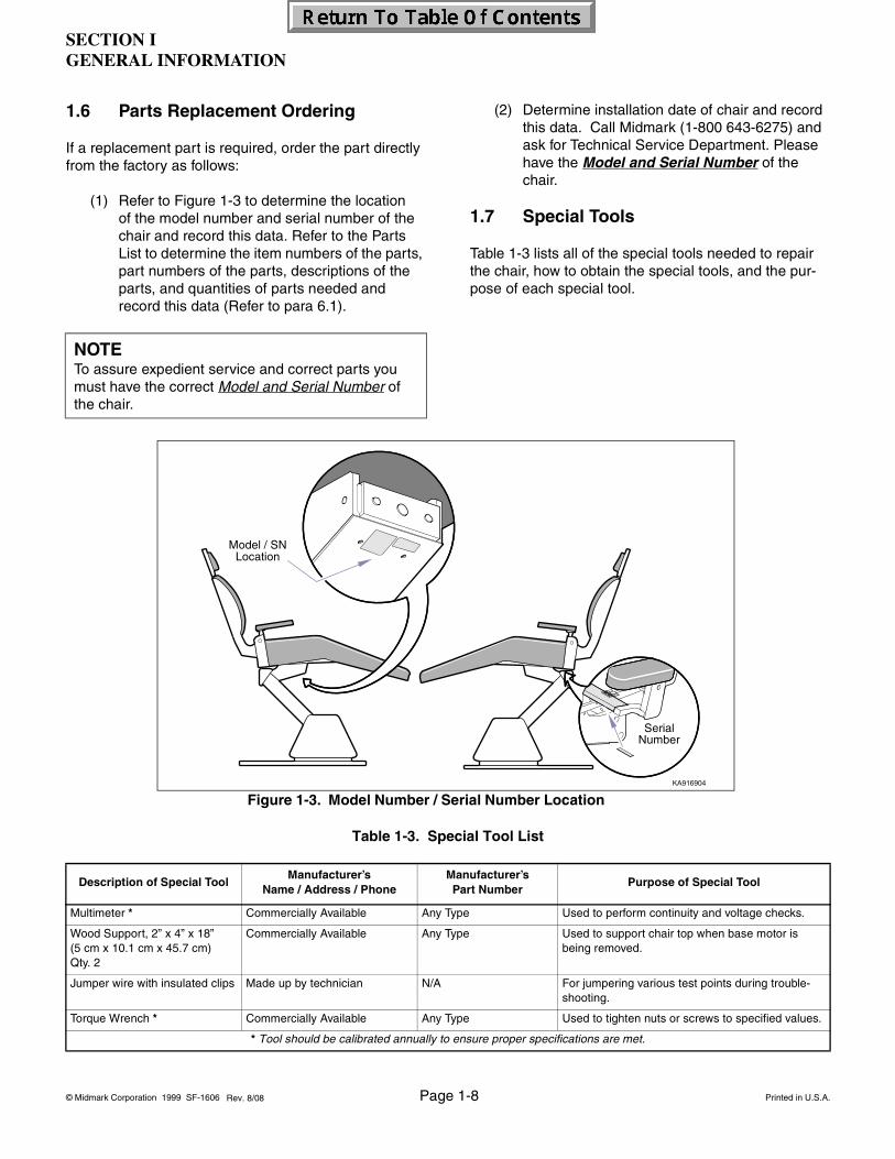
(1) Refer to Figure 1-3 to determine the location of the model number and serial number of the chair and record this data. Refer to the Parts List to determine the item numbers of the parts, part numbers of the parts, descriptions of the parts, and quantities of parts needed and record this data (Refer to para 6.1).
(2) Determine installation date of chair and record this data. Call Midmark (1-800 643-6275) and ask for Technical Service Department. Please have the Model and Serial Number of the chair.
1.7 Special Tools
Table 1-3 lists all of the special tools needed to repair the chair, how to obtain the special tools, and the pur-pose of each special tool.
NOTETo assure expedient service and correct parts you must have the correct Model and Serial Number of the chair.
Table 1-3. Special Tool List
Description of Special ToolManufacturer’s
Name / Address / Phone Manufacturer’sPart Number
Purpose of Special Tool
Multimeter * Commercially Available Any Type Used to perform continuity and voltage checks.
Wood Support, 2” x 4” x 18” (5 cm x 10.1 cm x 45.7 cm)Qty. 2
Commercially Available Any Type Used to support chair top when base motor is being removed.
Jumper wire with insulated clips Made up by technician N/A For jumpering various test points during trouble-shooting.
Torque Wrench * Commercially Available Any Type Used to tighten nuts or screws to specified values.
* Tool should be calibrated annually to ensure proper specifications are met.
Figure 1-3. Model Number / Serial Number Location
SerialNumber
Model / SNLocation
Rev. 8/08

SECTION IGENERAL INFORMATION
© Midmark Corporation 1999 SF-1606 Page 1-9 Printed in U.S.A.3/06
SECTION IITESTING AND TROUBLESHOOTING
© Midmark Corporation 1999 SF-1606 Page 2-1 Printed in U.S.A.
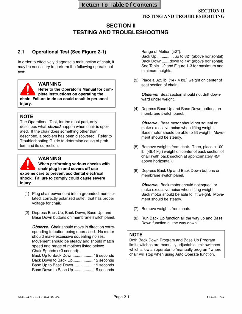
2.1 Operational Test (See Figure 2-1)
In order to effectively diagnose a malfunction of chair, it may be necessary to perform the following operational test:
(1) Plug chair power cord into a grounded, non-iso-lated, correctly polarized outlet, that has proper voltage for chair.
(2) Depress Back Up, Back Down, Base Up, and Base Down buttons on membrane switch panel.
Observe. Chair should move in direction corre-sponding to button being depressed. No motor should make excessive squealing noises. Movement should be steady and should match speed and range of motions listed below:Chair Speeds (±3 second):Back Up to Back Down...................15 secondsBack Down to Back Up...................15 secondsBase Up to Base Down ..................15 secondsBase Down to Base Up ..................15 seconds
Range of Motion (±2°):Back Up ............... up to 82° (above horizontal)Back Down.......down to 14° (above horizontal)See Table 1-2 and Figure 1-3 for maximum and minimum heights.
(3) Place a 325 lb. (147.4 kg.) weight on center of seat section of chair.
Observe. Seat section should not drift down-ward under weight.
(4) Depress Base Up and Base Down buttons on membrane switch panel.
Observe. Base motor should not squeal or make excessive noise when lifting weight. Base motor should be able to lift weight. Move-ment should be steady.
(5) Remove weights from chair. Then, place a 100 lb. (45.4 kg.) weight on center of back section of chair (with back section at approximately 45º above horizontal).
(6) Depress Back Up and Back Down buttons on membrane switch panel.
Observe. Back motor should not squeal or make excessive noise when lifting weight. Back motor should be able to lift weight. Move-ment should be steady.
(7) Remove weights from chair.
(8) Run Back Up function all the way up and Base Down function all the way down.
WARNINGRefer to the Operator’s Manual for com-plete instructions on operating the
chair. Failure to do so could result in personal injury.
NOTEThe Operational Test, for the most part, only describes what should happen when chair is oper-ated. If the chair does something other than described, a problem has been discovered. Refer to Troubleshooting Guide to determine cause of prob-lem and its correction.
WARNINGWhen performing various checks with chair plug in and covers off use
extreme care to prevent accidental electrical shock. Failure to comply could cause severe injury.
NOTEBoth Back Down Program and Base Up Program limit switches are manually adjustable limit switches which allow an operator to “manually program” where chair will stop when using Auto Operate function.
SECTION IITESTING AND TROUBLESHOOTING

SECTION IITESTING AND TROUBLESHOOTING
© Midmark Corporation 1999 SF-1606 Page 2-2 Printed in U.S.A.
Figure 2-1. Operational Test
KA917001i
90
Rotation Lock Lever(Biltmore Classic Only)
Auto Exit
Auto Operate
Back Up
Back Down
Base Down
Base Up
Foot Switch
AuxiliarySwitch
(Biltmore Classic Only)
Rev. 3/03

SECTION IITESTING AND TROUBLESHOOTING
© Midmark Corporation 1999 SF-1606 Page 2-3 Printed in U.S.A.
(9) Depress Auto Operate button on membrane switch panel.
Observe. Back Down function should run until its limit switch is tripped (Back Down Program limit switch), stopping it. Base Up function should run until its limit switch is tripped (Base Up Program limit switch), stop-ping it. Check both limit switches to verify that they were tripped.
(10) Depress Auto Exit button on membrane switch panel.
Observe. Back Up function should run until its limit switch trips (Back Up limit switch), stopping it. Base Down function should run until its limit switch trips (Base Down limit switch), stopping it. Check both limit switches to verify that they were tripped.
(11) Slide headrest in and out stopping at different positions. Push gently against headrest at each position.
Observe. Headrest should not require exces-sive force to position. When in a position, headrest should not move when a slight pres-sure is applied.
(12) Rotate chair top until it hits a stop. Then rotate chair top in opposite direction until it hits a stop.
Observe. Chair top should rotate smoothly and easily; not requiring excessive force. The chair top should be able to be rotated from stop to stop which is 90° or 45° in each direction from centerline of chair.
(13) Depress Rotation Lock lever to locked posi-tion. Attempt to rotate chair top.
Observe. Chair top should not be able to be rotated when Rotation Lock lever is engaged.
(14) Rotate armrests out of way to side. Return each armrest back to normal position.
Observe. Armrests should be able to be rotated out of way easily and should not require excessive force. When armrests are returned they should detente into their normal position without excessive side-to-side play.
(15) Depress Back Up, Back Down, Base Up, Base Down, Auto Exit, and Auto Operate buttons on foot control.
Observe. When each of the buttons on foot control are depressed, appropriate function should activate.
(16) Depress Auto Exit (Yellow) and /or Base Down membrane or foot switch. As chair descends, push upward on bottom lift arm cover until one or both of the Safety Bail Limit switches oper-ate.
Observe. When bottom lift arm cover contacts and operates Safety Bail Limit switch(es) chair should immediately stop its descent. Releasing bottom lift arm cover, returning Safety Bail Limit switch(es) to normally closed position, chair should continue to descend. When in Auto Exit, after Back Section reaches its upward program position, returning Safety Bail switch(es) to the normally closed (NC) position will not cause Base to descend. Oper-ating Base Down membrane or foot switch will cause chair to descend.
SECTION IITESTING AND TROUBLESHOOTING
© Midmark Corporation 1999 SF-1606 Page 2-4 Printed in U.S.A.
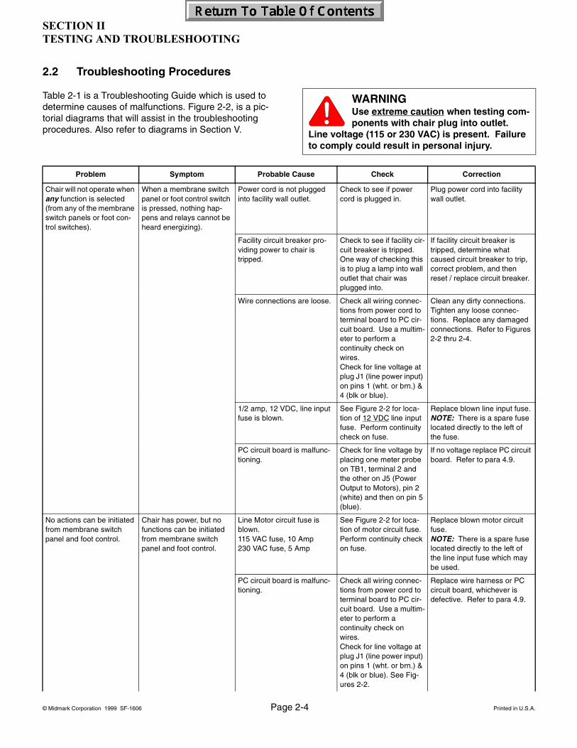
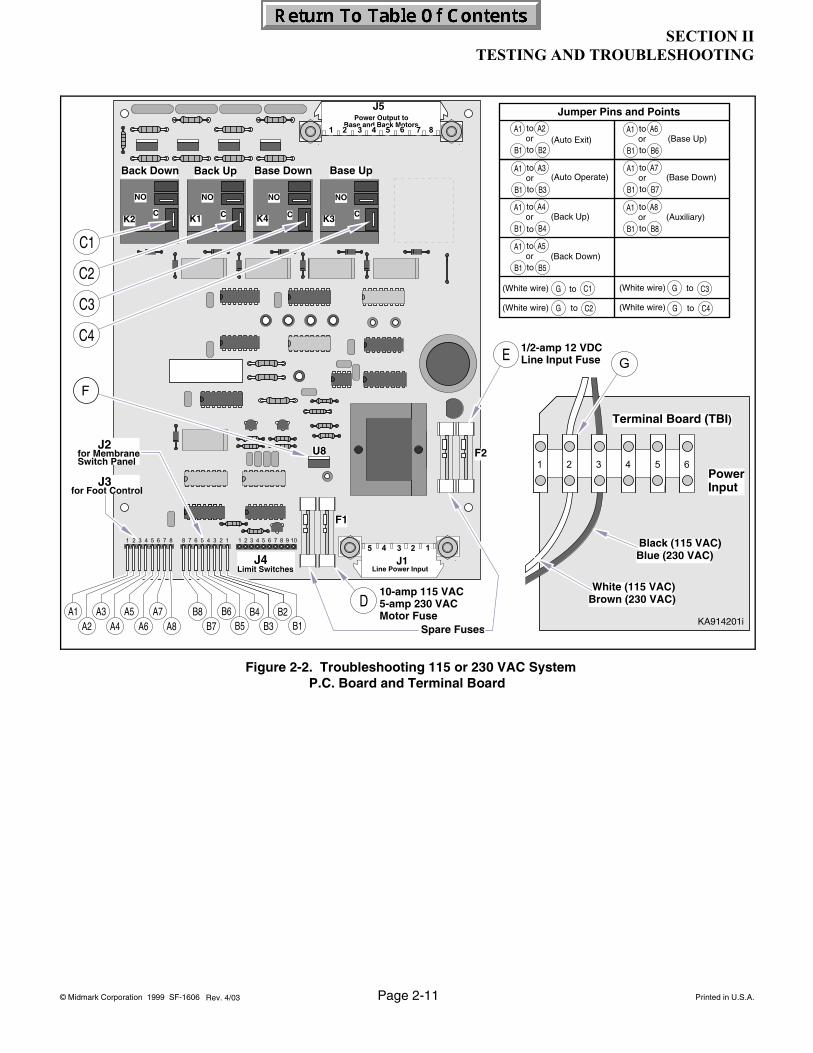
2.2 Troubleshooting Procedures
Table 2-1 is a Troubleshooting Guide which is used to determine causes of malfunctions. Figure 2-2, is a pic-torial diagrams that will assist in the troubleshooting procedures. Also refer to diagrams in Section V.
WARNINGUse extreme caution when testing com-ponents with chair plug into outlet.
Line voltage (115 or 230 VAC) is present. Failure to comply could result in personal injury.
Problem Symptom Probable Cause Check Correction
Chair will not operate when any function is selected (from any of the membrane switch panels or foot con-trol switches).
When a membrane switch panel or foot control switch is pressed, nothing hap-pens and relays cannot be heard energizing).
Power cord is not plugged into facility wall outlet.
Check to see if power cord is plugged in.
Plug power cord into facility wall outlet.
Facility circuit breaker pro-viding power to chair is tripped.
Check to see if facility cir-cuit breaker is tripped. One way of checking this is to plug a lamp into wall outlet that chair was plugged into.
If facility circuit breaker is tripped, determine what caused circuit breaker to trip, correct problem, and then reset / replace circuit breaker.
Wire connections are loose. Check all wiring connec-tions from power cord to terminal board to PC cir-cuit board. Use a multim-eter to perform a continuity check on wires.Check for line voltage at plug J1 (line power input) on pins 1 (wht. or brn.) & 4 (blk or blue).
Clean any dirty connections. Tighten any loose connec-tions. Replace any damaged connections. Refer to Figures 2-2 thru 2-4.
1/2 amp, 12 VDC, line input fuse is blown.
See Figure 2-2 for loca-tion of 12 VDC line input fuse. Perform continuity check on fuse.
Replace blown line input fuse.NOTE: There is a spare fuse located directly to the left of the fuse.
PC circuit board is malfunc-tioning.
Check for line voltage by placing one meter probe on TB1, terminal 2 and the other on J5 (Power Output to Motors), pin 2 (white) and then on pin 5 (blue).
If no voltage replace PC circuit board. Refer to para 4.9.
No actions can be initiated from membrane switch panel and foot control.
Chair has power, but no functions can be initiated from membrane switch panel and foot control.
Line Motor circuit fuse is blown.115 VAC fuse, 10 Amp230 VAC fuse, 5 Amp
See Figure 2-2 for loca-tion of motor circuit fuse. Perform continuity check on fuse.
Replace blown motor circuit fuse.NOTE: There is a spare fuse located directly to the left of the line input fuse which may be used.
PC circuit board is malfunc-tioning.
Check all wiring connec-tions from power cord to terminal board to PC cir-cuit board. Use a multim-eter to perform a continuity check on wires. Check for line voltage at plug J1 (line power input) on pins 1 (wht. or brn.) & 4 (blk or blue). See Fig-ures 2-2.
Replace wire harness or PC circuit board, whichever is defective. Refer to para 4.9.
SECTION IITESTING AND TROUBLESHOOTING
© Midmark Corporation 1999 SF-1606 Page 2-5 Printed in U.S.A.
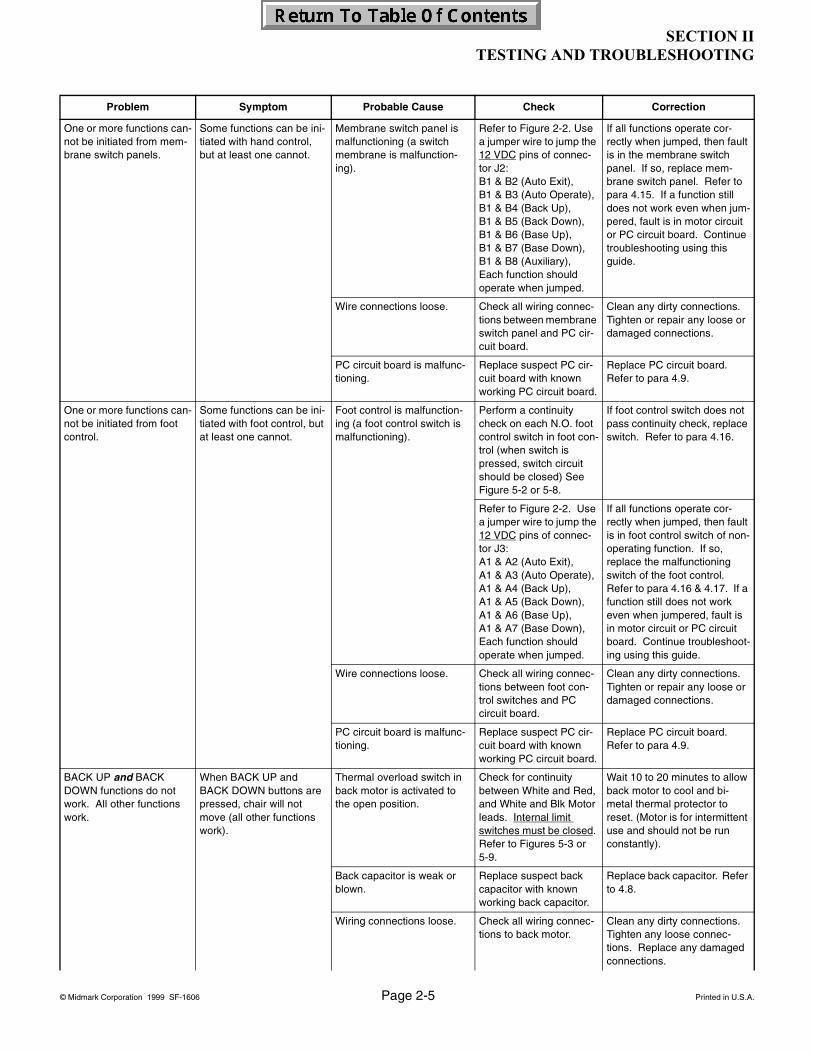
One or more functions can-not be initiated from mem-brane switch panels.
Some functions can be ini-tiated with hand control, but at least one cannot.
Membrane switch panel is malfunctioning (a switch membrane is malfunction-ing).
Refer to Figure 2-2. Use a jumper wire to jump the 12 VDC pins of connec-tor J2:B1 & B2 (Auto Exit),B1 & B3 (Auto Operate),B1 & B4 (Back Up),B1 & B5 (Back Down),B1 & B6 (Base Up),B1 & B7 (Base Down),B1 & B8 (Auxiliary),Each function should operate when jumped.
If all functions operate cor-rectly when jumped, then fault is in the membrane switch panel. If so, replace mem-brane switch panel. Refer to para 4.15. If a function still does not work even when jum-pered, fault is in motor circuit or PC circuit board. Continue troubleshooting using this guide.
Wire connections loose. Check all wiring connec-tions between membrane switch panel and PC cir-cuit board.
Clean any dirty connections. Tighten or repair any loose or damaged connections.
PC circuit board is malfunc-tioning.
Replace suspect PC cir-cuit board with known working PC circuit board.
Replace PC circuit board. Refer to para 4.9.
One or more functions can-not be initiated from foot control.
Some functions can be ini-tiated with foot control, but at least one cannot.
Foot control is malfunction-ing (a foot control switch is malfunctioning).
Perform a continuity check on each N.O. foot control switch in foot con-trol (when switch is pressed, switch circuit should be closed) See Figure 5-2 or 5-8.
If foot control switch does not pass continuity check, replace switch. Refer to para 4.16.
Refer to Figure 2-2. Use a jumper wire to jump the 12 VDC pins of connec-tor J3:A1 & A2 (Auto Exit),A1 & A3 (Auto Operate),A1 & A4 (Back Up),A1 & A5 (Back Down),A1 & A6 (Base Up),A1 & A7 (Base Down),Each function should operate when jumped.
If all functions operate cor-rectly when jumped, then fault is in foot control switch of non-operating function. If so, replace the malfunctioning switch of the foot control. Refer to para 4.16 & 4.17. If a function still does not work even when jumpered, fault is in motor circuit or PC circuit board. Continue troubleshoot-ing using this guide.
Wire connections loose. Check all wiring connec-tions between foot con-trol switches and PC circuit board.
Clean any dirty connections. Tighten or repair any loose or damaged connections.
PC circuit board is malfunc-tioning.
Replace suspect PC cir-cuit board with known working PC circuit board.
Replace PC circuit board. Refer to para 4.9.
BACK UP and BACK DOWN functions do not work. All other functions work.
When BACK UP and BACK DOWN buttons are pressed, chair will not move (all other functions work).
Thermal overload switch in back motor is activated to the open position.
Check for continuity between White and Red, and White and Blk Motor leads. Internal limit switches must be closed. Refer to Figures 5-3 or5-9.
Wait 10 to 20 minutes to allow back motor to cool and bi-metal thermal protector to reset. (Motor is for intermittent use and should not be run constantly).
Back capacitor is weak or blown.
Replace suspect back capacitor with known working back capacitor.
Replace back capacitor. Refer to 4.8.
Wiring connections loose. Check all wiring connec-tions to back motor.
Clean any dirty connections. Tighten any loose connec-tions. Replace any damaged connections.
Problem Symptom Probable Cause Check Correction

SECTION IITESTING AND TROUBLESHOOTING
© Midmark Corporation 1999 SF-1606 Page 2-6 Printed in U.S.A.
BACK UP and BACK DOWN functions do not work. All other functions work (continued)
When BACK UP and BACK DOWN buttons are pressed, chair will not move (all other functions work) (continued)
Back motor is malfunction-ing.
Replace suspect back motor with known work-ing back motor assembly.
Replace back motor. Refer to para 4.7.
BACK UP function works, but BACK DOWN function does not or BACK DOWN function works, but BACK UP function does not. All other functions work.
Back motor runs in one direction, but not the other.
Wiring connections loose. Check all wiring connec-tions from PC circuit board to back motor assembly.
Clean any dirty connections. Tighten any loose connec-tions. Replace any damaged connections.
Membrane switch panel is malfunctioning (BACK UP or BACK DOWN switch mem-brane is malfunctioning).
Refer to Figures 2-2, 5-2 and 5-8. Use a jumper wire to jump 12 VDC pins of connector J2:B1 & B4 (Back Up),B1 & B5 (Back Down),Each function should operate when jumped.
If both functions operate cor-rectly when jumped, then fault is in the membrane switch panel. If so, replace mem-brane switch panel. Refer to para 4.15. If a function still does not work even when jum-pered, fault is in motor circuit or PC circuit board.
Back Up Limit Switch is mal-functioning or is out of adjustment.
Perform continuity check on N.C. Back Up Limit Switch and check limit switch adjustment.
Replace Normally Closed, Back Up Limit Switch. Refer to para 4.12.
Back motor is malfunction-ing.
Replace suspect back motor with known work-ing back motor.
Replace back motor. Refer to para 4.7.
Back Down or Back Up motor internal limit switch is malfunctioning or out of adjustment.
Perform continuity check on motor internal limit switches.
Replace back motor. Refer to para 4.7.
Relay (K1 or K2) for Up or Down function on PC circuit board is malfunctioning).
Refer to Figure 2-2 for this check. Use a jumper wire to jump line voltage Test Points C2 and G; Back Up function should run. Use a jumper wire to jump line voltage Test Points C1 and G; Back Down function should run.If motor runs when a relay is jumped, fault is in membrane switch panel, wiring, or PC circuit board. If motor does not run when a relay is jumped, fault is in wiring or back motor.
Replace PC circuit board. Refer to para 4.9.
BASE UP and BASE DOWN functions do not work. All other functions work.
When BASE UP and BASE DOWN buttons are pressed, chair will not move (all other functions work).
Thermal overload switch in base motor is activated to the open position.
Check for continuity between Blue (common) and White (115 VAC) or Brown (230 VAC), and Blue (common) and Blk Motor leads.
Wait 10 to 20 minutes to allow back motor to cool and bi-metal thermal protector to reset. (Motor is for intermittent use and should not be run constantly).
Base capacitor is weak or blown.
Replace suspect base capacitor with known working capacitor.
Replace base capacitor. Refer to 4.3.
Problem Symptom Probable Cause Check Correction
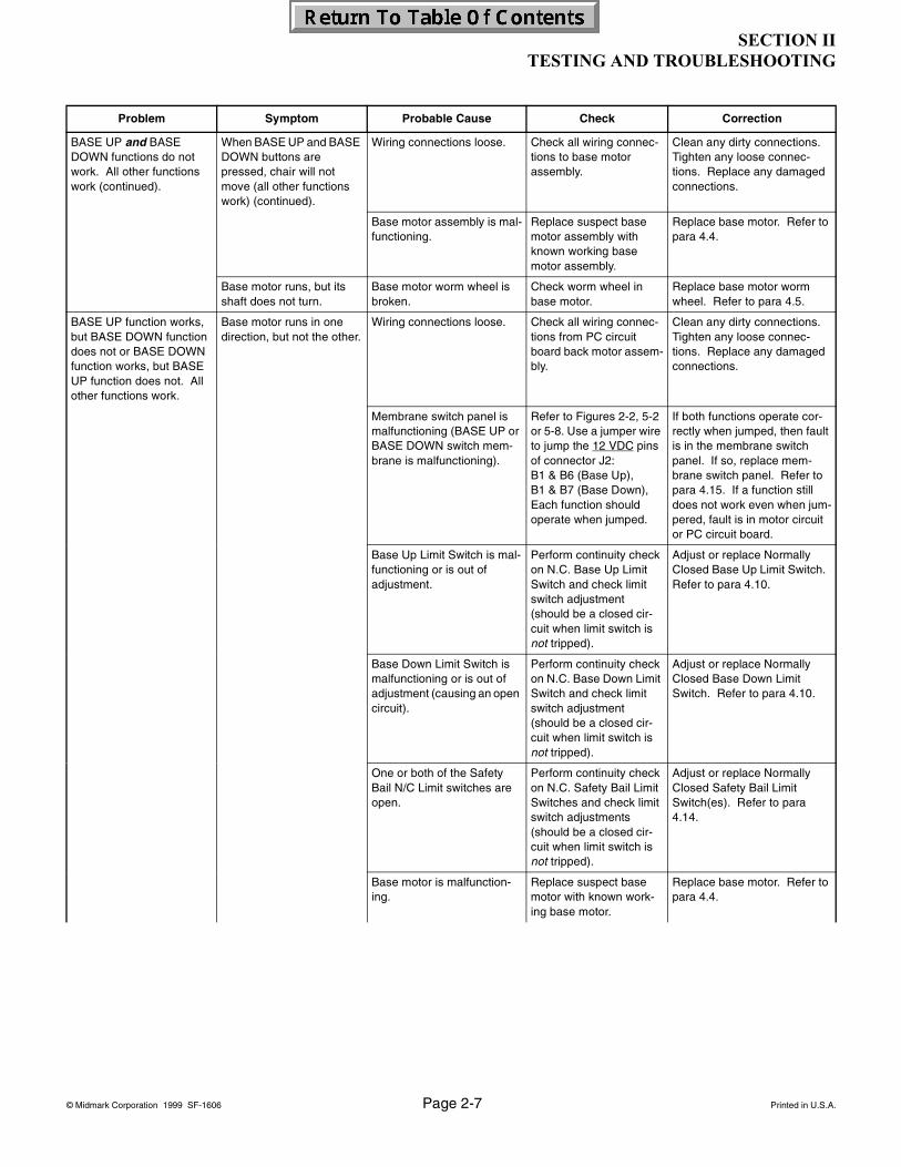
SECTION IITESTING AND TROUBLESHOOTING
© Midmark Corporation 1999 SF-1606 Page 2-7 Printed in U.S.A.
BASE UP and BASE DOWN functions do not work. All other functions work (continued).
When BASE UP and BASE DOWN buttons are pressed, chair will not move (all other functions work) (continued).
Wiring connections loose. Check all wiring connec-tions to base motor assembly.
Clean any dirty connections. Tighten any loose connec-tions. Replace any damaged connections.
Base motor assembly is mal-functioning.
Replace suspect base motor assembly with known working base motor assembly.
Replace base motor. Refer to para 4.4.
Base motor runs, but its shaft does not turn.
Base motor worm wheel is broken.
Check worm wheel in base motor.
Replace base motor worm wheel. Refer to para 4.5.
BASE UP function works, but BASE DOWN function does not or BASE DOWN function works, but BASE UP function does not. All other functions work.
Base motor runs in one direction, but not the other.
Wiring connections loose. Check all wiring connec-tions from PC circuit board back motor assem-bly.
Clean any dirty connections. Tighten any loose connec-tions. Replace any damaged connections.
Membrane switch panel is malfunctioning (BASE UP or BASE DOWN switch mem-brane is malfunctioning).
Refer to Figures 2-2, 5-2 or 5-8. Use a jumper wire to jump the 12 VDC pins of connector J2:B1 & B6 (Base Up),B1 & B7 (Base Down),Each function should operate when jumped.
If both functions operate cor-rectly when jumped, then fault is in the membrane switch panel. If so, replace mem-brane switch panel. Refer to para 4.15. If a function still does not work even when jum-pered, fault is in motor circuit or PC circuit board.
Base Up Limit Switch is mal-functioning or is out of adjustment.
Perform continuity check on N.C. Base Up Limit Switch and check limit switch adjustment (should be a closed cir-cuit when limit switch is not tripped).
Adjust or replace Normally Closed Base Up Limit Switch. Refer to para 4.10.
Base Down Limit Switch is malfunctioning or is out of adjustment (causing an open circuit).
Perform continuity check on N.C. Base Down Limit Switch and check limit switch adjustment (should be a closed cir-cuit when limit switch is not tripped).
Adjust or replace Normally Closed Base Down Limit Switch. Refer to para 4.10.
One or both of the Safety Bail N/C Limit switches are open.
Perform continuity check on N.C. Safety Bail Limit Switches and check limit switch adjustments (should be a closed cir-cuit when limit switch is not tripped).
Adjust or replace Normally Closed Safety Bail Limit Switch(es). Refer to para 4.14.
Base motor is malfunction-ing.
Replace suspect base motor with known work-ing base motor.
Replace base motor. Refer to para 4.4.
Problem Symptom Probable Cause Check Correction
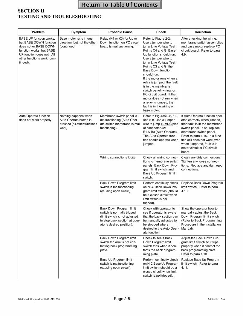
SECTION IITESTING AND TROUBLESHOOTING
© Midmark Corporation 1999 SF-1606 Page 2-8 Printed in U.S.A.
BASE UP function works, but BASE DOWN function does not or BASE DOWN function works, but BASE UP function does not. All other functions work (con-tinued).
Base motor runs in one direction, but not the other (continued).
Relay (K4 or K3) for Up or Down function on PC circuit board is malfunctioning.
Refer to Figure 2-2. Use a jumper wire to jump Line Voltage Test Points C4 and G; Base Up function should run. Use a jumper wire to jump Line Voltage Test Points C3 and G; the Base Down function should run.If the motor runs when a relay is jumped, the fault is in the membrane switch panel, wiring, or PC circuit board. If the motor does not run when a relay is jumped, the fault is in the wiring or base motor.
After checking the wiring, membrane switch assemblies and base motor replace PC circuit board. Refer to para 4.9.
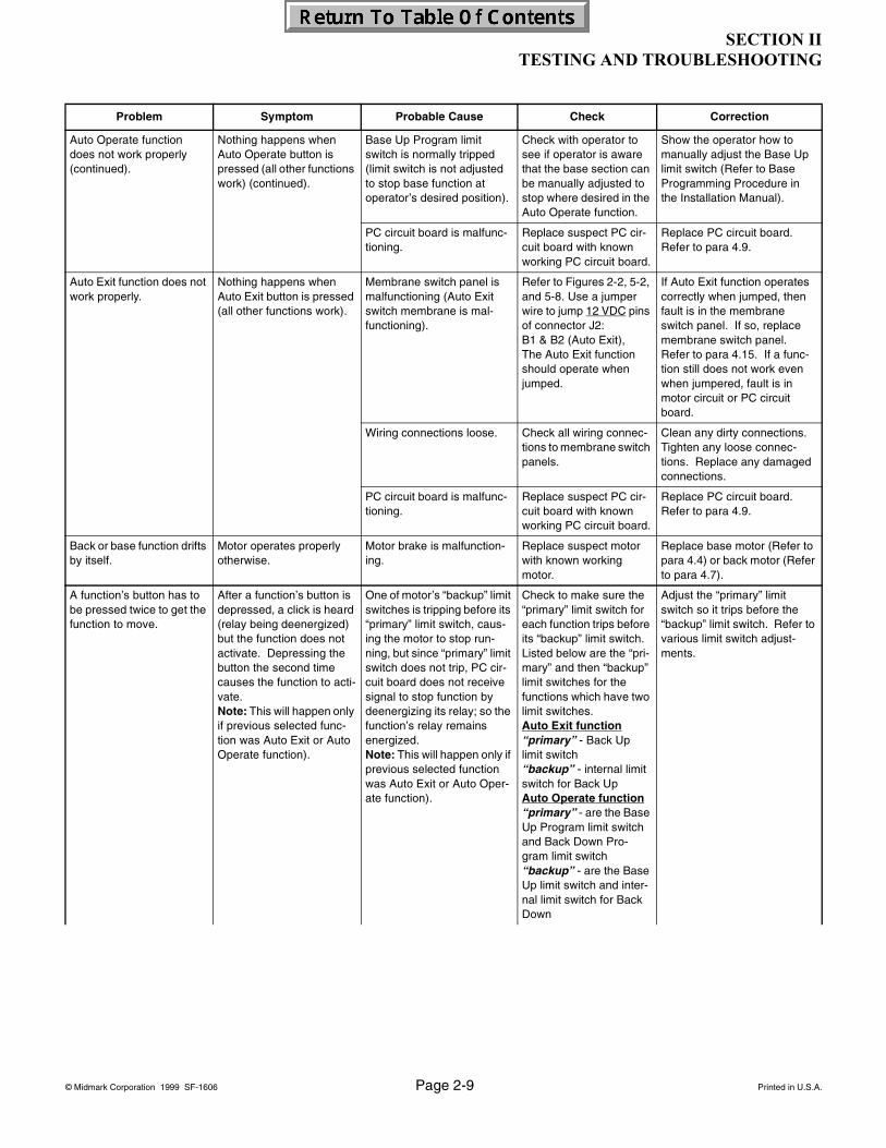
Auto Operate function does not work properly.
Nothing happens when Auto Operate button is pressed (all other functions work).
Membrane switch panel is malfunctioning (Auto Oper-ate switch membrane is mal-functioning).
Refer to Figures 2-2, 5-2, and 5-8. Use a jumper wire to jump 12 VDC pins of connector J2:B1 & B3 (Auto Operate),The Auto Operate func-tion should operate when jumped.
If Auto Operate function oper-ates correctly when jumped, then fault is in the membrane switch panel. If so, replace membrane switch panel. Refer to para 4.15. If a func-tion still does not work even when jumpered, fault is in motor circuit or PC circuit board.
Wiring connections loose. Check all wiring connec-tions to membrane switch panels, Back Down Pro-gram limit switch, and Base Up Program limit switch.
Clean any dirty connections. Tighten any loose connec-tions. Replace any damaged connections.
Back Down Program limit switch is malfunctioning (causing open circuit).
Perform continuity check on N.C. Back Down Pro-gram limit switch (should be a closed circuit when limit switch is not tripped).
Replace Back Down Program limit switch. Refer to para 4.13.
Back Down Program limit switch is normally tripped (limit switch is not adjusted to stop back section at oper-ator’s desired position).
Check with operator to see if operator is aware that the back section can be manually adjusted to be stopped where desired in the Auto Oper-ate function.
Show the operator how to manually adjust the Back Down Program limit switch (Refer to Back Programming Procedure in the Installation Manual).
Back Down Program limit switch trip arm is not con-tacting back programming plate.
Check to see if Back Down Program limit switch trips when it con-tacts the back program-ming plate.
Adjust the Back Down Pro-gram limit switch so it trips properly when it contact the back programming plate. Refer to para 4.13.
Base Up Program limit switch is malfunctioning (causing open circuit).
Perform continuity check on N.C Base Up Program limit switch (should be a closed circuit when limit switch is not tripped).
Replace Base Up Program limit switch. Refer to para 4.11.
Problem Symptom Probable Cause Check Correction
SECTION IITESTING AND TROUBLESHOOTING
© Midmark Corporation 1999 SF-1606 Page 2-9 Printed in U.S.A.
Auto Operate function does not work properly (continued).
Nothing happens when Auto Operate button is pressed (all other functions work) (continued).
Base Up Program limit switch is normally tripped (limit switch is not adjusted to stop base function at operator’s desired position).
Check with operator to see if operator is aware that the base section can be manually adjusted to stop where desired in the Auto Operate function.
Show the operator how to manually adjust the Base Up limit switch (Refer to Base Programming Procedure in the Installation Manual).
PC circuit board is malfunc-tioning.
Replace suspect PC cir-cuit board with known working PC circuit board.
Replace PC circuit board. Refer to para 4.9.
Auto Exit function does not work properly.
Nothing happens when Auto Exit button is pressed (all other functions work).
Membrane switch panel is malfunctioning (Auto Exit switch membrane is mal-functioning).
Refer to Figures 2-2, 5-2, and 5-8. Use a jumper wire to jump 12 VDC pins of connector J2:B1 & B2 (Auto Exit),The Auto Exit function should operate when jumped.
If Auto Exit function operates correctly when jumped, then fault is in the membrane switch panel. If so, replace membrane switch panel. Refer to para 4.15. If a func-tion still does not work even when jumpered, fault is in motor circuit or PC circuit board.
Wiring connections loose. Check all wiring connec-tions to membrane switch panels.
Clean any dirty connections. Tighten any loose connec-tions. Replace any damaged connections.
PC circuit board is malfunc-tioning.
Replace suspect PC cir-cuit board with known working PC circuit board.
Replace PC circuit board. Refer to para 4.9.
Back or base function drifts by itself.
Motor operates properly otherwise.
Motor brake is malfunction-ing.
Replace suspect motor with known working motor.
Replace base motor (Refer to para 4.4) or back motor (Refer to para 4.7).
A function’s button has to be pressed twice to get the function to move.
After a function’s button is depressed, a click is heard (relay being deenergized) but the function does not activate. Depressing the button the second time causes the function to acti-vate.Note: This will happen only if previous selected func-tion was Auto Exit or Auto Operate function).
One of motor’s “backup” limit switches is tripping before its “primary” limit switch, caus-ing the motor to stop run-ning, but since “primary” limit switch does not trip, PC cir-cuit board does not receive signal to stop function by deenergizing its relay; so the function’s relay remains energized.Note: This will happen only if previous selected function was Auto Exit or Auto Oper-ate function).
Check to make sure the “primary” limit switch for each function trips before its “backup” limit switch. Listed below are the “pri-mary” and then “backup” limit switches for the functions which have two limit switches.Auto Exit function“primary” - Back Up limit switch“backup” - internal limit switch for Back UpAuto Operate function“primary” - are the Base Up Program limit switch and Back Down Pro-gram limit switch“backup” - are the Base Up limit switch and inter-nal limit switch for Back Down
Adjust the “primary” limit switch so it trips before the “backup” limit switch. Refer to various limit switch adjust-ments.
Problem Symptom Probable Cause Check Correction

SECTION IITESTING AND TROUBLESHOOTING
© Midmark Corporation 1999 SF-1606 Page 2-10 Printed in U.S.A.
Chair moves fine for light patient, but will not move or moves slowly for very heavy patient
Heavy patients cause chair to malfunction.
Chair overloaded with too heavy of a patient.
Maximum weight capac-ity is 325 lbs (147.4 kg).
Inform chair operator of weight limitation.
Low voltage is being sup-plied to chair.
Check voltage at wall receptacle - should be between 110.0 to 126.0 VAC on 115 VAC units or 220 to 252 VAC on 230 VAC units.
Correct low voltage situation at wall receptacle.
Capacitor for suspect func-tion is weak.
Replace suspect capaci-tor with known working capacitor.
Replace base capacitor (refer to para 4.3) or back capacitor (refer to para 4.8).
Motor screw threads are dry or dirty, causing friction.
Check for foreign matter and lack of lubricant on screw threads.
Clean all foreign matter off of screw threads. Coat threads with STP treatment oil or equivalent. If motor is still lacking power, replace it.
Motor is exceedingly noisy. Noisy motor. Foreign matter on screw threads and / or lack of lubri-cant.
Check for foreign matter and lack of lubricant on screw threads.
Clean all foreign matter off of screw threads. Coat ball threads with STP treatment oil or equivalent. If motor is still noisy, replace it.
Headrest is difficult to adjust or does not stay in position.
Excessive force is required to position the headrest.
Headrest slide is too tight and needs adjusted.
Check adjustment of headrest slide.
Adjust the headrest slide assembly. Refer to para 4.19.
Headrest does not lock into a position or slides down-ward on own.
Headrest slide is too loose and needs adjusted.
Check adjustment of headrest slide.
Adjust the headrest slide assembly. Refer to para 4.19.
Rotational base not work-ing.
Brake is off, but chair top is binding when rotated.
Brake is out of adjustment (needs loosened).
Check adjustment of brake.
Adjust brake. Refer to para 4.18.
Brake lever is difficult to engage.
Brake is out of adjustment (needs loosened).
Check adjustment of brake.
Adjust brake. Refer to para 4.18.
Chair top can still be rotated when BRAKE lever is in locked position.
Brake is out of adjustment (needs tightened).
Check adjustment of brake.
Adjust brake. Refer to para 4.18.
Brake pads worn. Check condition of brake pads.
Replace brake pads. Refer to para 4.18.
Armrest is not working properly.
Armrest is hard to raise, rotate, or will not lock into place when returned to normal armrest position.
There is dirt, burrs, corro-sion, or foreign matter in the armrest bearing or armrest post.
Check for dirt, burrs, cor-rosion, or foreign matter in the armrest bearing.
Clean the armrest post and armrest bearing. Use crocus cloth or a file to remove any burrs.
Problem Symptom Probable Cause Check Correction
Rev. 3/10
SECTION IITESTING AND TROUBLESHOOTING
© Midmark Corporation 1999 SF-1606 Page 2-11 Printed in U.S.A.
Jumper Pins and Points
KA914201i
J5 Power Output to Base and Back Motors
J1 Line Power Input
A1A2
A3A4
A5A6
A7A8 B1
B2B3
B4B5
B6B7
B8
C3
C4
D
Spare Fuses
10-amp 115 VAC5-amp 230 VACMotor Fuse
1/2-amp 12 VDC Line Input Fuse
Back Down Back Up Base UpBase Down
J2 for MembraneSwitch Panel
J3 for Foot Control
Black (115 VAC)
Terminal Board (TBI)
J4 Limit Switches
U8
PowerInput
U8
F1
F2
K2 K1 K3K4
NO NO NO NO
CCCC
C1
C2
E
Blue (230 VAC)
White (115 VAC)Brown (230 VAC)
A1
B1(Auto Exit)
(Auto Operate)
(Back Up)
(Back Down)
(Base Up)
(Base Down)
(Auxiliary)
to A2or to B2
(White wire) G
A1
B1
to A6or to B6
A1
B1
to A3or to B3
A1
B1
to A4or to B4
A1
B1
to A5or to B5
A1
B1
to A7or to B7
A1
B1
to A8or to B8
C1
C2
C3to
to
to
to (White wire) C4
(White wire)
(White wire)
G
GG
Figure 2-2. Troubleshooting 115 or 230 VAC SystemP.C. Board and Terminal Board
Rev. 4/03

SECTION IITESTING AND TROUBLESHOOTING
© Midmark Corporation 1999 SF-1606 Page 2-12 Printed in U.S.A.

SECTION IIISCHEDULED MAINTENANCE
© Midmark Corporation 1999 SF-1606 Page 3-1 Printed in U.S.A.
3.1 Scheduled Maintenance
Table 3-1 is a Scheduled Maintenance Chart which lists
inspections and services that should be performed peri-odically on the chair. These inspections and services should be performed as often as indicated in the chart.
Interval Inspection or Service What to Do
Semi-annually Obvious damage Visually check condition of chair for obvious damage such as: cracks in components, missing com-ponents, dents in components, or any other visible damage which would cause chair to be unsafe to operate or would compromise its performance. Repair chair as necessary.
Fasteners / hardware Check chair for missing or loose fasteners / hardware. Replace any missing hardware and tighten any loose hardware as necessary.
Warning and instructional decals
Check for missing or illegible decals. Replace decals as necessary.
Pivot points / moving parts / accessories
Lubricate all exposed pivot points, moving parts, and accessories with silicone based lubricant.
Membrane switch panels Check each switch on both membrane switch panels for proper operation. Depress each mem-brane switch to make sure selected function operates. If any switch does not work, replace mem-brane switch panel. Refer to para 4.15.
Foot control Check each switch on foot control for proper operation. Depress each foot control switch to make sure selected function operates when its button is depressed. If any switch does not work, replace malfunctioning switch. Refer to para 4.16 or 4.17.
Base and Back motors Check both motors for proper operation in up and down directions. If motor makes excessive noise, clean all foreign matter off screw threads and coat threads with STP treatment oil or equiva-lent. If motor is weak or hums, replace its capacitor. Refer to para 4.3 thru para 4.8.
Headrest slide mecha-nism
Check headrest slide mechanism for proper operation by sliding headrest up and down. Headrest should not take excessive force to move but should require a slight force to begin movement. If necessary, adjust headrest slide assembly. Refer to para 4.19.
Rotation bearing Check rotation bearing for proper operation. Unlock brake and rotate chair top. Chair top should rotate smoothly and easily 45° in each direction from centerline of chair. If binding occurs, adjust brake. Refer to para 4.18. Move footrest release lever to brake position and attempt to rotate chair top. Chair top should not be able to be moved. If necessary, adjust brake. Refer to para 4.18.
Armrest Check armrest. Rotate it to the side and back to its normal position. If armrest is hard to rotate, or will not lock into place, clean armrest post and bearing. Use crocus cloth or a file to remove any burrs. Coat post and bearing with silicone based lubricant.
Limit switches. Check to make sure “primary” limit switch for each function trips before its “backup” limit switch. Listed below are“primary” and “backup” limit switches for each function.
Auto Exit function“primary” - Back Up limit switch“backup” - Internal (motor) limit switch for Back UpAuto Operate function“primary” - Base Up Program limit switch and Back Down Program limit switch“backup” - Base Up limit switch and internal (motor)l limit switch for Back DownBack Up function“primary” - Back up limit switch“backup” - Internal (motor) limit switch for Back UpBack Down function“primary” - Internal (motor) limit for Back Down“backup” - NoneBase Up function“primary” - Base up limit switch“backup” - NoneBase Down function“primary” =Base down limit switch“backup” = None
NOTE: If necessary, adjust a “primary” limit switch to trip before a “backup” limit switch.
SECTION IIISCHEDULED MAINTENANCE

SECTION IIISCHEDULED MAINTENANCE
© Midmark Corporation 1999 SF-1606 Page 3-2 Printed in U.S.A.
Safety Bail Limit Switches
Test both Safety Bail Limit switches to assure they function, stopping the chair’s descent in Auto Exit and Base Down modes. Press upward on the bottom lift arm cover during the descent. If descent continues adjust or replace malfunctioning limit switch(es). Refer to para 4.14).
Upholstery Check all upholstery for rips, tears, or excessive wear.
Accessories Check that all accessories have all of their components and that they function properly.
Operational Test Perform an Operational Test to determine if the chair is operating within its specifications (Refer to para 2.1). Replace or adjust any malfunctioning components.
Interval Inspection or Service What to Do

SECTION IVMAINTENANCE / SERVICE
© Midmark Corporation 1999 SF-1606 Page 4-1 Printed in U.S.A.
4.1 Introduction
The following paragraphs contain removal, installation, repair, and adjustment procedures for the dental chair.
4.2 Upholstery
A. Removal
(1) Raise chair up to its highest position and recline the back to 45°.
(2) Move headrest (1, Figure 4-1) assembly upward.
(3) Pull upward on back cushion skirt (2) to sepa-rate velcro on skirt from velcro on chair back.
(4) Pull upward on chair back cushion (3) to release it from mounting studs (4) on back and remove cushion.
(5) Using a 3/8" socket, remove four screws (1, Figure 4-2) that secure hinges (2) to seat cush-ion (3) and remove cushion.
B. Installation
(1) Install four screws (1, Figure 4-2) in bottom of seat and hand tighten two turns.
(2) Place two hinges (2) up into a vertical position and lower seat cushion (3) onto chair so it rests on hinges (2).
(3) Rotate hinges (2) downward toward screws (1) allowing screws to slide into slots of hinges (2).
(4) Tighten four screws (1).
WARNINGRefer to Operator Manual for complete instructions on operating the dental
chair. Failure to do so could result in personal injury.
NOTEPerform an operational test on the dental chair after repair is completed to confirm repair was properly made and that all malfunctions were repaired.
Figure 4-1. Upholstery
Figure 4-2. Upholstery
SECTION IVMAINTENANCE / SERVICE INSTRUCTIONS

SECTION IVMAINTENANCE / SERVICE
© Midmark Corporation 1999 SF-1606 Page 4-2 Printed in U.S.A.
4.3 Base Capacitor
A. Removal
(1) Unplug chair power cord.
(2) Remove R.H. (1, Figure 4-3) and L.H. (2) base covers (three screws each).
(3) Remove center base cover (3) (four screws).
(4) Using a screwdriver, pry up on tab (A, Figure 4-4) of mounting bracket (1) and remove capac-itor (2).
(5) Remove cap (3) from capacitor (2).
(6) Discharge capacitor (2).
(7) Tag and disconnect four wires (4) and remove capacitor (2).
B. Installation
(1) Connect four wires (4, Figure 4-4) to capacitor (2).
(2) Install capacitor cap (3).
(3) Position capacitor (2) on mounting bracket (1) making sure capacitor is held firmly in place with tabs of bracket.
(4) Install center base cover (3, Figure 4-3) on mounting brackets and secure with four screws.
(5) Install L.H. (2) and R.H. (1) base cover on cen-ter base cover (3) (three screws each).
(6) Plug chair power cord into wall outlet and check operation.
WARNINGUnplug chair power cord from wall out-let before removing covers or working
on chair. Failure to comply could result in per-sonal injury.
Figure 4-3. Base Motor Capacitor
WARNING Using a screwdriver with an insulated handle, jumper across capacitor termi-
nals to discharge capacitor before touching ter-minals or wires. Failure to comply could result in serious personal injury.
Figure 4-4. Base Motor Capacitor

SECTION IVMAINTENANCE / SERVICE
© Midmark Corporation 1999 SF-1606 Page 4-3 Printed in U.S.A.
4.4 Base Motor
A. Removal
(1) Align chair on base, engage brake, and, if nec-essary, fold any chair mounted accessories inward, over chair.
(2) Unplug chair power cord.
(3) Remove R.H. (1, Figure 4-5 ) and L.H. (2) base covers (three screws each).
(4) Remove center base cover (3) (four screws).
(5) Remove R.H. (1, Figure 4-6), Center (2) and L.H. (3) platform covers (4 screws).
(6) Pull outward on one corner of bottom lift arm cover (4) until it clears standoff (5). Repeat step for other corner and remove cover (4).
(7) If base motor is operable:
a. Plug chair power cord into wall outlet.
b. Raise BASE UP function all the way up.
c. Position two wood 2 x 4’s (18” long [45.7 cm] ) (1, Figure 4-7) beneath top support (2) , then lower chair so it barely rests on the wood supports.
WARNINGRotate chair so it is aligned straight on base and engage the brake to prevent
movement. If there are chair mounted accesso-ries, assure they are folded inward, over chair, to prevent side loading during base motor removal and assembly procedures.
Figure 4-5. Base Motor Removal
DANGERMake sure that chair top is securely supported before starting to remove
base motor. Failure to do so could result in chair top collapsing which could cause serious per-sonal injury or death.
NOTERun base motor until top support just rests against wood supports. Do not draw chair down so base motor is binding against wood supports.
Figure 4-6. Base Motor Removal

SECTION IVMAINTENANCE / SERVICE
© Midmark Corporation 1999 SF-1606 Page 4-4 Printed in U.S.A.
d. Remove four screws (1, Figure 4-8), lock-washers (2), and trunnion retainer plate (3) from frame (4).
e. Carefully lower chair onto wood supports, until motor shaft and trunnion block disen-gages (5) from frame (4).
f. Disconnect power supply to chair.
g. Remove mounting brackets (1, Figure 4-9) (four screws).
h. Carefully pull outward on left side of mounting plate (2) and position plate so base motor (3) can be accessed.
i. Unplug base motor wire harness (1, Figure 4-10) and disconnect cable clamp (2) from base.
j. Remove one of the retaining rings (3) and the pin (4) securing clevis (5) to base mounting bracket (6).
Figure 4-7. Base Motor Removal
Figure 4-8 Base Motor Removal
WARNINGDisconnect the power from the chair. Failure to comply could result in per-
sonal injury.
NOTECut any cable ties or remove any cables from cable clamps which are restricting movement of mounting plate (2) when its left side is being pulled outward.
Figure 4-9. Base Motor Removal

SECTION IVMAINTENANCE / SERVICE
© Midmark Corporation 1999 SF-1606 Page 4-5 Printed in U.S.A.
k.. Remove ground wire (7) from motor (one screw and lockwasher).
l. Remove two washers (8); one from each side of trunnion (9).
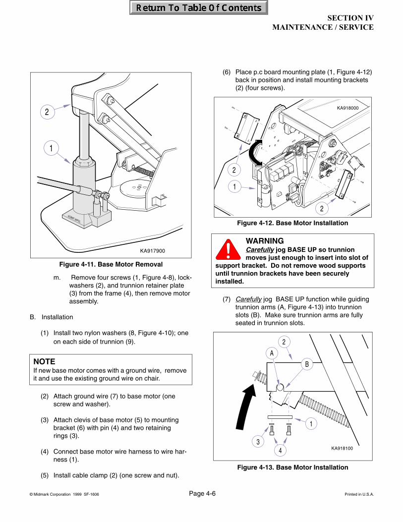
m. Remove four screws (1, Figure 4-8), lock-washers (2), and trunnion retainer plate (3) from the frame (4), then remove motor assembly.
(8) If base motor is not operable:
a. Disconnect power supply to chair
b. Remove mounting brackets (1, Figure 4-9) (four screws).
c. Carefully pull outward on left side of mounting plate (2) and position plate so base motor (3) can be accessed.
d. Unplug base motor wire harness (1, Figure 4-10) and disconnect cable clamp (2) from base.
e. Remove one of the retaining rings (3) and the pin (4) securing clevis (5) to base mounting bracket (6).
f.. Remove ground wire (7) from motor (one screw and lockwasher).
g. Remove two washers (8); one from each side of trunnion (9).
h. Place a jack (1, Figure 4-11) beneath top support (2) to support it while removing base motor.
l. Using jack (1), elevate chair to access shaft end of motor assembly.
WARNINGDisconnect the power from the chair. Failure to comply could result in per-
sonal injury.
Figure 4-10. Base Motor Removal
NOTECut any cable ties or remove any cables from cable clamps which are restricting movement of mounting plate (2) when its left side is being pulled outward.
DANGERMake sure that chair top is securely supported before starting to remove
base motor. Failure to do so could result in chair top collapsing which could cause serious per-sonal injury or death.
EQUIPMENT ALERTDo not apply pressure to top support with jack until after base motor has been dis-
connected from base mounting bracket or damage could occur to motor assembly.
SECTION IVMAINTENANCE / SERVICE
© Midmark Corporation 1999 SF-1606 Page 4-6 Printed in U.S.A.
m. Remove four screws (1, Figure 4-8), lock-washers (2), and trunnion retainer plate (3) from the frame (4), then remove motor assembly.
B. Installation
(1) Install two nylon washers (8, Figure 4-10); one on each side of trunnion (9).
(2) Attach ground wire (7) to base motor (one screw and washer).
(3) Attach clevis of base motor (5) to mounting bracket (6) with pin (4) and two retaining rings (3).
(4) Connect base motor wire harness to wire har-ness (1).
(5) Install cable clamp (2) (one screw and nut).
(6) Place p.c board mounting plate (1, Figure 4-12) back in position and install mounting brackets (2) (four screws).
(7) Carefully jog BASE UP function while guiding trunnion arms (A, Figure 4-13) into trunnion slots (B). Make sure trunnion arms are fully seated in trunnion slots.
NOTEIf new base motor comes with a ground wire, remove it and use the existing ground wire on chair.
Figure 4-11. Base Motor Removal
WARNINGCarefully jog BASE UP so trunnion moves just enough to insert into slot of
support bracket. Do not remove wood supports until trunnion brackets have been securely installed.
Figure 4-12. Base Motor Installation
Figure 4-13. Base Motor Installation
SECTION IVMAINTENANCE / SERVICE
© Midmark Corporation 1999 SF-1606 Page 4-7 Printed in U.S.A.
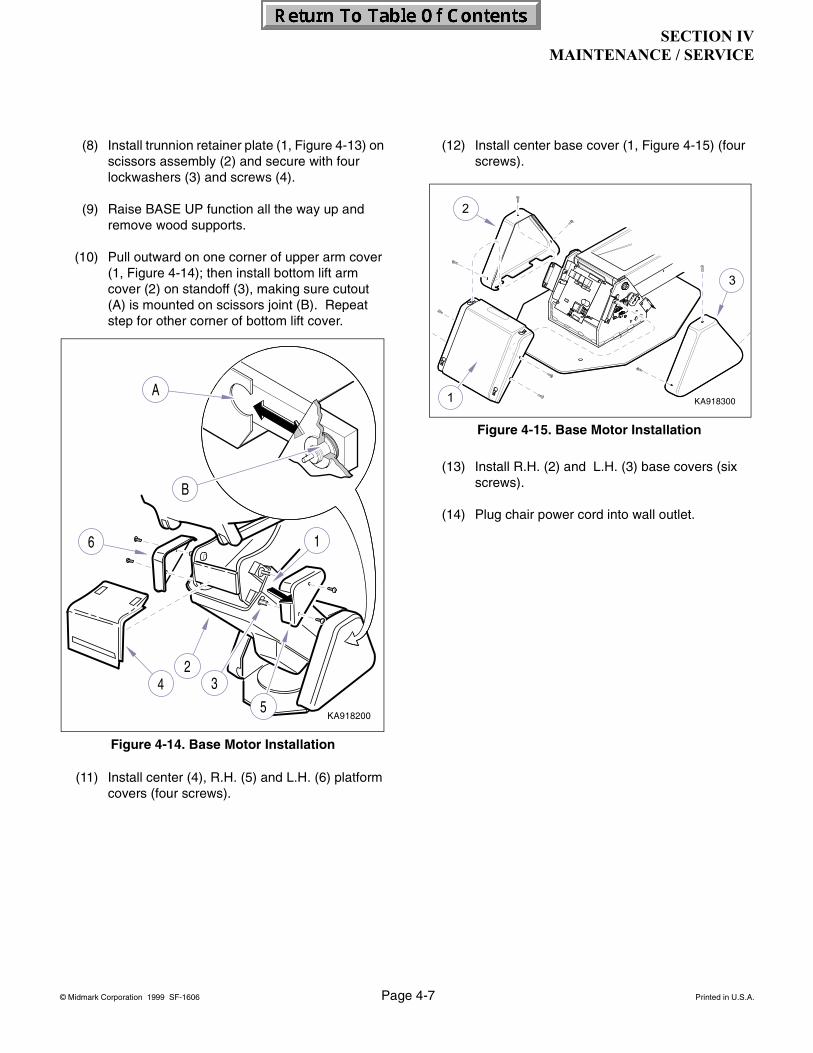
(8) Install trunnion retainer plate (1, Figure 4-13) on scissors assembly (2) and secure with four lockwashers (3) and screws (4).
(9) Raise BASE UP function all the way up and remove wood supports.
(10) Pull outward on one corner of upper arm cover (1, Figure 4-14); then install bottom lift arm cover (2) on standoff (3), making sure cutout (A) is mounted on scissors joint (B). Repeat step for other corner of bottom lift cover.
(11) Install center (4), R.H. (5) and L.H. (6) platform covers (four screws).
(12) Install center base cover (1, Figure 4-15) (four screws).
(13) Install R.H. (2) and L.H. (3) base covers (six screws).
(14) Plug chair power cord into wall outlet.
Figure 4-14. Base Motor Installation
Figure 4-15. Base Motor Installation
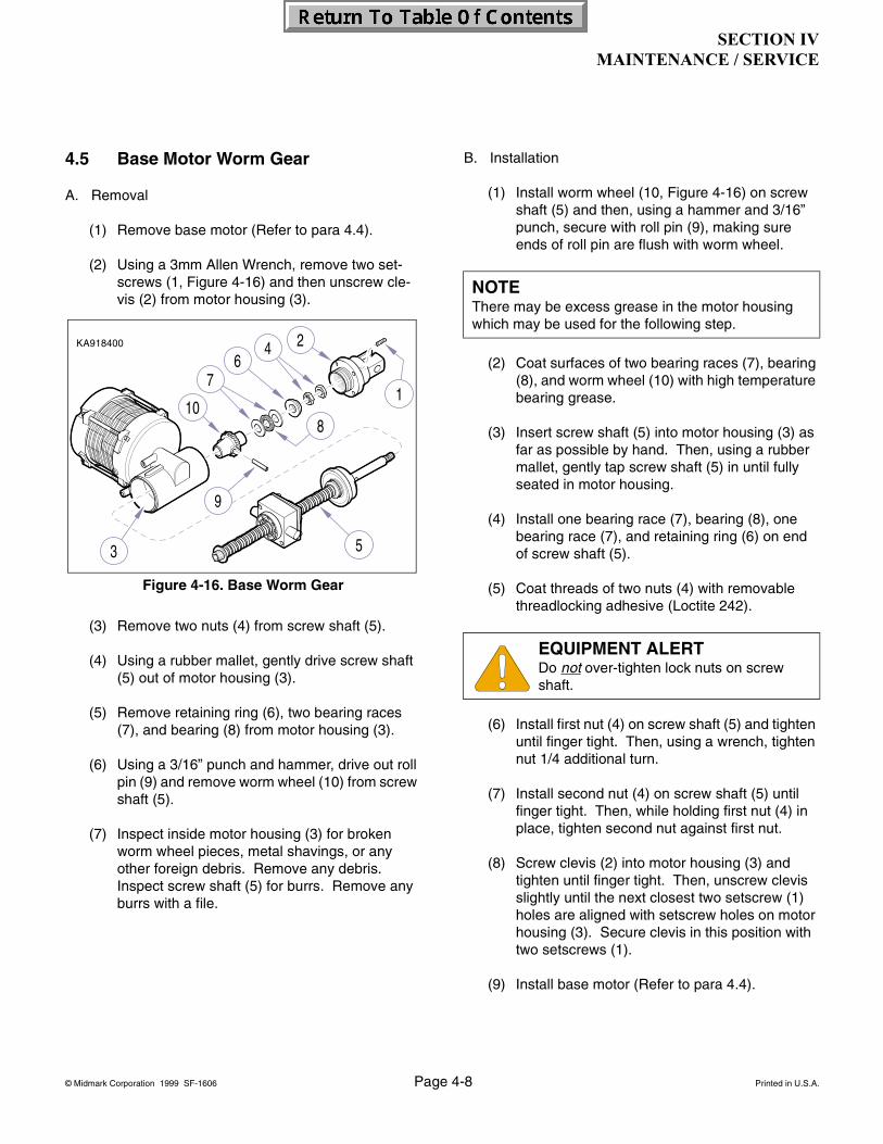
SECTION IVMAINTENANCE / SERVICE
© Midmark Corporation 1999 SF-1606 Page 4-8 Printed in U.S.A.
4.5 Base Motor Worm Gear
A. Removal
(1) Remove base motor (Refer to para 4.4).
(2) Using a 3mm Allen Wrench, remove two set-screws (1, Figure 4-16) and then unscrew cle-vis (2) from motor housing (3).
(3) Remove two nuts (4) from screw shaft (5).
(4) Using a rubber mallet, gently drive screw shaft (5) out of motor housing (3).
(5) Remove retaining ring (6), two bearing races (7), and bearing (8) from motor housing (3).
(6) Using a 3/16” punch and hammer, drive out roll pin (9) and remove worm wheel (10) from screw shaft (5).
(7) Inspect inside motor housing (3) for broken worm wheel pieces, metal shavings, or any other foreign debris. Remove any debris. Inspect screw shaft (5) for burrs. Remove any burrs with a file.
B. Installation
(1) Install worm wheel (10, Figure 4-16) on screw shaft (5) and then, using a hammer and 3/16” punch, secure with roll pin (9), making sure ends of roll pin are flush with worm wheel.
(2) Coat surfaces of two bearing races (7), bearing (8), and worm wheel (10) with high temperature bearing grease.
(3) Insert screw shaft (5) into motor housing (3) as far as possible by hand. Then, using a rubber mallet, gently tap screw shaft (5) in until fully seated in motor housing.
(4) Install one bearing race (7), bearing (8), one bearing race (7), and retaining ring (6) on end of screw shaft (5).
(5) Coat threads of two nuts (4) with removable threadlocking adhesive (Loctite 242).
(6) Install first nut (4) on screw shaft (5) and tighten until finger tight. Then, using a wrench, tighten nut 1/4 additional turn.
(7) Install second nut (4) on screw shaft (5) until finger tight. Then, while holding first nut (4) in place, tighten second nut against first nut.
(8) Screw clevis (2) into motor housing (3) and tighten until finger tight. Then, unscrew clevis slightly until the next closest two setscrew (1) holes are aligned with setscrew holes on motor housing (3). Secure clevis in this position with two setscrews (1).
(9) Install base motor (Refer to para 4.4).
Figure 4-16. Base Worm Gear
NOTEThere may be excess grease in the motor housing which may be used for the following step.
EQUIPMENT ALERTDo not over-tighten lock nuts on screw shaft.

SECTION IVMAINTENANCE / SERVICE
© Midmark Corporation 1999 SF-1606 Page 4-9 Printed in U.S.A.
4.6 Base Motor Trunnion
A. Removal
(1) Remove the base motor (refer to para 4.4).
(2) Using an 8mm allen wrench, remove the socket head screw, flat washer, and lock washer (1, Figure 4-17) from motor shaft (2).
(3) Unscrew the trunnion assembly (3) from the motor shaft (2).
B. Disassembly
(1) Using a 3/16” allen wrench, remove the two socket head set screws and lock washers (4, Figure 4-17) and remove the trunnion plate (5).
(2) Separate the drive nut (6), pin (7) and, trunnion block (8).
C. Assembly
(1) Place the drive nut (6, Figure 4-17) into the trunnion block (8) and install the pin (7).
(2) Place trunnion plate (5) onto trunnion block (8) and secure with two socket head screws and lock washers (4).
D. Installation
(1) Install trunnion assembly (3) on motor shaft (2).
(2) Install socket head screw, flat washer, and lock washer (1) onto motor shaft (2).
(3) Install base motor (Refer to para 4.4).
Figure 4-17. Base Motor Trunnion
NOTEThe trunnion plate (5) is intentionally deformed in order to apply pressure to the drive nut (6).
EQUIPMENT ALERTTrunnion plate (5, Figure 4-16) must face toward the motor when installing trunnion
assembly (3) on motor shaft (2).
EQUIPMENT ALERTLubricate both studs on trunnion block and motor shaft with an extreme pressure lubri-
cant such as Magnalube-G Teflon Lubricant or equiv-alent.

SECTION IVMAINTENANCE / SERVICE
© Midmark Corporation 1999 SF-1606 Page 4-10 Printed in U.S.A.
4.7 Back Motor
A. Removal
(1) Unplug chair power cord.
(2) Remove seat upholstery (1, Figure 4-18) by loosening four screws (2) that secure seat upholstery to seat hinges (3).
(3) Disconnect motor wire harness (1, Figure 4-19 ) from wire harness.
(4) Remove two ground wires (2) by removing lock-nut, screw and lockwasher (3) from frame.
(5) While supporting back section, remove two push nut caps (1, Figure 4-20 ), two leg support rollers (2), two small retaining rings (3), and two large E-clips (4) on tow bar shaft (5).
(6) Loosen set screw (6) that secures motor actua-tor tube (A) to tow bar shaft (5).
(7) Separate tow bar shaft (5) from seat support bar assemblies (7).
(8) While supporting back motor assembly (8), remove four screws and lock washers (9) and remove back motor assembly.
Figure 4-18. Back Motor
Figure 4-19. Back Motor
WARNINGBe sure Back section is supported before disconnecting Back Motor
assembly. Failure to comply may result in per-sonal injury.
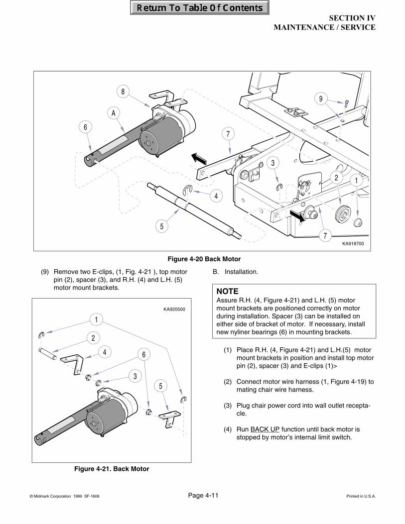
SECTION IVMAINTENANCE / SERVICE
© Midmark Corporation 1999 SF-1606 Page 4-11 Printed in U.S.A.
(9) Remove two E-clips, (1, Fig. 4-21 ), top motor pin (2), spacer (3), and R.H. (4) and L.H. (5) motor mount brackets.
B. Installation.
(1) Place R.H. (4, Figure 4-21) and L.H.(5) motor mount brackets in position and install top motor pin (2), spacer (3) and E-clips (1)>
(2) Connect motor wire harness (1, Figure 4-19) to mating chair wire harness.
(3) Plug chair power cord into wall outlet recepta-cle.
(4) Run BACK UP function until back motor is stopped by motor’s internal limit switch.
Figure 4-21. Back Motor
Figure 4-20 Back Motor
NOTEAssure R.H. (4, Figure 4-21) and L.H. (5) motor mount brackets are positioned correctly on motor during installation. Spacer (3) can be installed on either side of bracket of motor. If necessary, install new nyliner bearings (6) in mounting brackets.
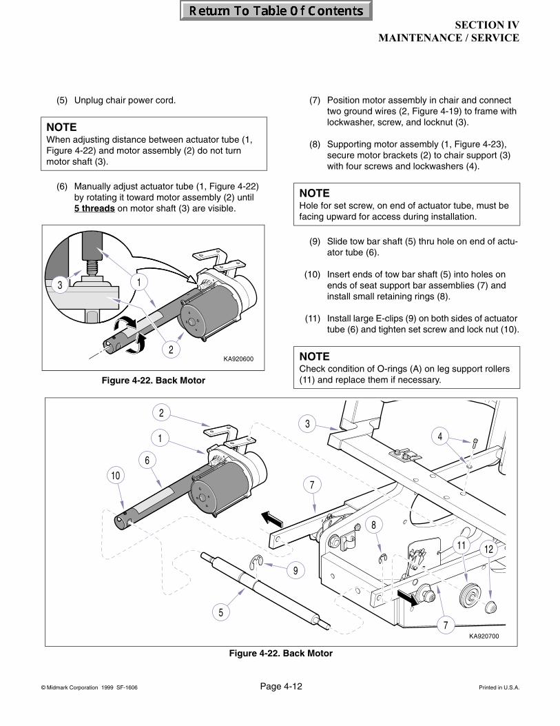
SECTION IVMAINTENANCE / SERVICE
© Midmark Corporation 1999 SF-1606 Page 4-12 Printed in U.S.A.
(5) Unplug chair power cord.
(6) Manually adjust actuator tube (1, Figure 4-22) by rotating it toward motor assembly (2) until 5 threads on motor shaft (3) are visible.
(7) Position motor assembly in chair and connect two ground wires (2, Figure 4-19) to frame with lockwasher, screw, and locknut (3).
(8) Supporting motor assembly (1, Figure 4-23), secure motor brackets (2) to chair support (3) with four screws and lockwashers (4).
(9) Slide tow bar shaft (5) thru hole on end of actu-ator tube (6).
(10) Insert ends of tow bar shaft (5) into holes on ends of seat support bar assemblies (7) and install small retaining rings (8).
(11) Install large E-clips (9) on both sides of actuator tube (6) and tighten set screw and lock nut (10).
NOTEWhen adjusting distance between actuator tube (1, Figure 4-22) and motor assembly (2) do not turn motor shaft (3).
Figure 4-22. Back Motor
NOTEHole for set screw, on end of actuator tube, must be facing upward for access during installation.
NOTECheck condition of O-rings (A) on leg support rollers (11) and replace them if necessary.
Figure 4-22. Back Motor

SECTION IVMAINTENANCE / SERVICE
© Midmark Corporation 1999 SF-1606 Page 4-13 Printed in U.S.A.
(12) Lubricate both ends of tow bar shaft and install leg support rollers (11) and push nut caps (12).
(13) Plug the chair into outlet and check operation.
(14) Install upholstery (refer to para 4.2)
4.8 Back Motor Capacitor
A. Removal
(1) Remove Base Motor (refer to para 4.4)
(2) Remove capacitor cover (1, Figure 4-24) (two screws).
(3) Discharge capacitor (2).
(4) Disconnect leads (3) and remove capacitor (2).
B. Installation
(1) Connect electrical leads (3, Figure 4- 24) to capacitor (2).
EQUIPMENT ALERTAssure all electrical leads are secured in existing cable clamps to prevent accidental
cutting when chair is in operation.
EQUIPMENT ALERTCheck to assure the internal motor limit switches (Back Up and Back Down) func-
tion correctly, stopping the motor at its extreme limits.
WARNING Using a screwdriver with an insulated handle, jumper across capacitor termi-
nals to discharge capacitor before touching ter-minals or wires. Failure to comply could result in serious personal injury.
EQUIPMENT ALERTAssure capacitor being installed is of same microfarad (Mfd) and voltage rating as one
being replaced.
Figure 4-24. Back Motor Capacitor
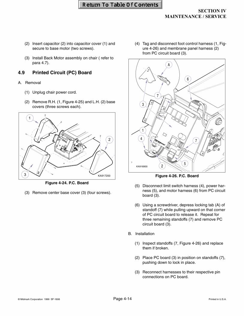
SECTION IVMAINTENANCE / SERVICE
© Midmark Corporation 1999 SF-1606 Page 4-14 Printed in U.S.A.
(2) Insert capacitor (2) into capacitor cover (1) and secure to base motor (two screws).
(3) Install Back Motor assembly on chair ( refer to para 4.7).
4.9 Printed Circuit (PC) Board
A. Removal
(1) Unplug chair power cord.
(2) Remove R.H. (1, Figure 4-25) and L.H. (2) base covers (three screws each).
(3) Remove center base cover (3) (four screws).
(4) Tag and disconnect foot control harness (1, Fig-ure 4-26) and membrane panel harness (2) from PC circuit board (3).
(5) Disconnect limit switch harness (4), power har-ness (5), and motor harness (6) from PC circuit board (3).
(6) Using a screwdriver, depress locking tab (A) of standoff (7) while pulling upward on that corner of PC circuit board to release it. Repeat for three remaining standoffs (7) and remove PC circuit board (3).
B. Installation
(1) Inspect standoffs (7, Figure 4-26) and replace them if broken.
(2) Place PC board (3) in position on standoffs (7), pushing down to lock in place.
(3) Reconnect harnesses to their respective pin connections on PC board.
Figure 4-24. P.C. Board
Figure 4-26. P.C. Board
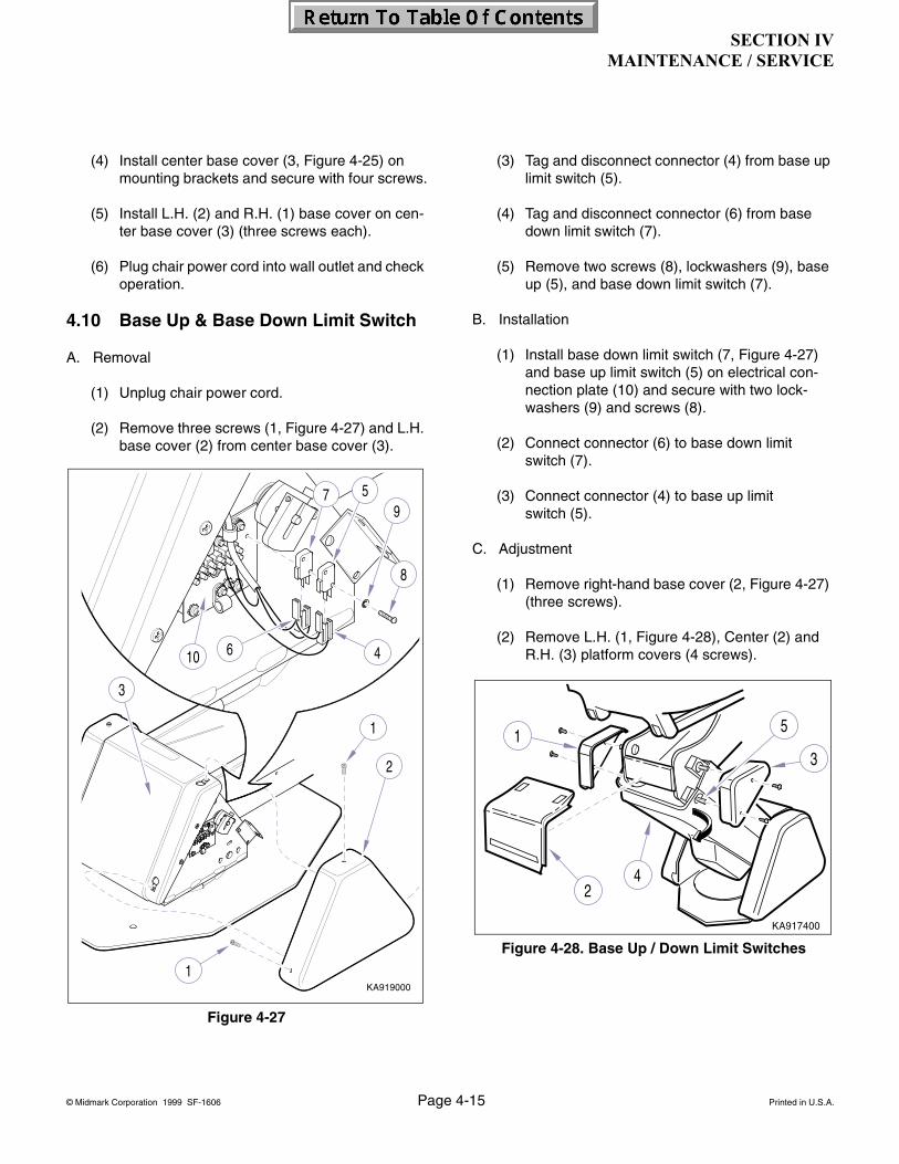
SECTION IVMAINTENANCE / SERVICE
© Midmark Corporation 1999 SF-1606 Page 4-15 Printed in U.S.A.
(4) Install center base cover (3, Figure 4-25) on mounting brackets and secure with four screws.
(5) Install L.H. (2) and R.H. (1) base cover on cen-ter base cover (3) (three screws each).
(6) Plug chair power cord into wall outlet and check operation.
4.10 Base Up & Base Down Limit Switch
A. Removal
(1) Unplug chair power cord.
(2) Remove three screws (1, Figure 4-27) and L.H. base cover (2) from center base cover (3).
(3) Tag and disconnect connector (4) from base up limit switch (5).
(4) Tag and disconnect connector (6) from base down limit switch (7).
(5) Remove two screws (8), lockwashers (9), base up (5), and base down limit switch (7).
B. Installation
(1) Install base down limit switch (7, Figure 4-27) and base up limit switch (5) on electrical con-nection plate (10) and secure with two lock-washers (9) and screws (8).
(2) Connect connector (6) to base down limit switch (7).
(3) Connect connector (4) to base up limit switch (5).
C. Adjustment
(1) Remove right-hand base cover (2, Figure 4-27) (three screws).
(2) Remove L.H. (1, Figure 4-28), Center (2) and R.H. (3) platform covers (4 screws).
Figure 4-27
Figure 4-28. Base Up / Down Limit Switches

SECTION IVMAINTENANCE / SERVICE
© Midmark Corporation 1999 SF-1606 Page 4-16 Printed in U.S.A.
(3) Pull outward on one corner of bottom lift arm cover (4) until it clears standoff (5). Repeat step for other corner and remove cover (4).
(4) Base Up Limit Switch Adjustment.
a. Loosen screw (1, Figure 4-29) and rotate cam (2) up off trip button (A) of Base Up limit switch (3).
b. Raise Base Up function all the way up until motor stops.
c. Lower Base Down function until flat washer (1, Figure 4-30) is 1/2” (1.27 cm) from face of trunnion nut (2).
d. Rotating in downward direction, adjust cam (2, Figure 4-29) so that it “just” oper-ates trip button (A) of Base Up limit switch (3); then tighten screw (1) on cam.
(5) Base Down Limit Switch Adjustment.
a. Loosen screw (4, Figure 4-29) and rotate cam (5) down off trip button (B) of Base Down limit switch (6).
WARNINGLimit switch cam adjustments must be done with table plugged in. Line volt-
age is present on terminal board near limit switches. Use care not to touch bare wires or ter-minals. Failure to comply could result in per-sonal injury.
EQUIPMENT ALERTWhen base motor reaches its limit, release Base Up control button quickly; motor is
binding at this point and damage to motor could occur.
Figure 4-29. Base Up / Down Limit Switches
NOTERotate Base Up limit switch cam (2, Figure 4-29) above switch trip button (A) and then downward to trip button during adjustment due to rotational direc-tion of cam (2).
CAUTIONDo not run Base Down function any lower than specified in step 7. Doing so could
allow chair to physically collide with itself, damaging motor, covers, or other components.
Figure 4-30. Base Up / Down Limit Switches
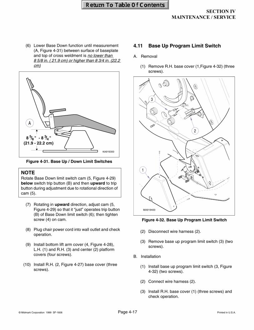
SECTION IVMAINTENANCE / SERVICE
© Midmark Corporation 1999 SF-1606 Page 4-17 Printed in U.S.A.
(6) Lower Base Down function until measurement (A, Figure 4-31) between surface of baseplate and top of cross weldment is no lower than 8 5/8 in. ( 21.9 cm) or higher than 8 3/4 in. (22.2 cm)
(7) Rotating in upward direction, adjust cam (5, Figure 4-29) so that it “just” operates trip button (B) of Base Down limit switch (6); then tighten screw (4) on cam.
(8) Plug chair power cord into wall outlet and check operation.
(9) Install bottom lift arm cover (4, Figure 4-28), L.H. (1) and R.H. (3) and center (2) platform covers (four screws).
(10) Install R.H. (2, Figure 4-27) base cover (three screws).
4.11 Base Up Program Limit Switch
A. Removal
(1) Remove R.H. base cover (1,Figure 4-32) (three screws).
(2) Disconnect wire harness (2).
(3) Remove base up program limit switch (3) (two screws).
B. Installation
(1) Install base up program limit switch (3, Figure 4-32) (two screws).
(2) Connect wire harness (2).
(3) Install R.H. base cover (1) (three screws) and check operation.
NOTERotate Base Down limit switch cam (5, Figure 4-29) below switch trip button (B) and then upward to trip button during adjustment due to rotational direction of cam (5).
Figure 4-31. Base Up / Down Limit Switches
Figure 4-32. Base Up Program Limit Switch

SECTION IVMAINTENANCE / SERVICE
© Midmark Corporation 1999 SF-1606 Page 4-18 Printed in U.S.A.
4.12 Back Up Limit Switch
A. Removal
(1) Remove seat upholstery (refer to para 4-2).
(2) Raise Base Up all way up and lower Back Down function all way down.
(3) Unplug chair power cord.
(4) Disconnect switch harness (1, Figure 4-33) from back up limit switch (2).
(5) Remove two screws (3), nut bar (4), back up limit switch (2), washers (5), and actuator (6) from limit switch plate (7).
B. Installation
(1) Assemble two screws (3, Figure 4-33), actuator (6), and two washers (5) on Back Up limit switch (2).
(2) Install back up limit switch assembly (2) on limit switch plate (7) positioning it as far toward foot end as possible and secure with nut bar (4).
(3) Connect switch harness (1) to back up limit switch (2).
C. Adjustment
(1) Raise Back Up function all way up (until Back Up limit switch is tripped).
(2) Distance between seat support bar assembly (1, Figure 4-34) and top cross brace (A) of seat platform (2) should be approximately 1/8” (.32 cm).
(3) If necessary, loosen two screws (3, Figure 4-33) and adjust back up limit switch (2) to trip earlier or later.Figure 4-33. Back Up Limit Switch
EQUIPMENT ALERTBe sure that Back Up Limit Switch trips to the “open” position before internal limit
switch in Back Motor trips.
NOTEIf necessary, disconnect switch harness and use an ohmmeter to determine if normally closed (C / NC) contacts have opened and reinstall switch harness.
EQUIPMENT ALERTSeat support bar assembly (1, Figure 4-34) and top cross brace (A) of seat plat-
form (2) should not come in contact when back is all way up.

SECTION IVMAINTENANCE / SERVICE
© Midmark Corporation 1999 SF-1606 Page 4-19 Printed in U.S.A.
4.13 Back Down Program Limit Switch
A. Removal
(1) Raise Base Up all way up and lower Back Down function all way down.
(2) Unplug chair from wall outlet.
(3) Remove seat upholstery (refer to para 4-2).
(4) Lift upward on seat support assembly (1, Figure 4-35) and place a support beneath it to hold it in place while working on Back Down Program Limit Switch (2).
(5) Disconnect wire harness (3) from back down program limit switch (2).
(6) Remove two screws (4), limit switch (2), and nut bar (5) from limit switch bracket (6).
B. Installation
(1) Install limit switch (2, Figure 4-35) on limit switch bracket (6) and secure with two screws (4) and nut bar (5).
(2) Connect wire harness (3).
C. Adjustment
(1) Run Auto Operate function and observe. If trip arm (A, Figure 4-36) bottoms out or does not trip when it comes into contact with pro-gramming plate (2), back down program limit switch (1) needs adjusted.
Figure 4-34. Back Up Limit Switch
EQUIPMENT ALERTAssure trip arm (A, Figure 4-36) does not bottom out on back down program limit
switch (1) body when it comes in contact with back down programming plate (2).
Figure 4-35. Back Down Program Limit Switch
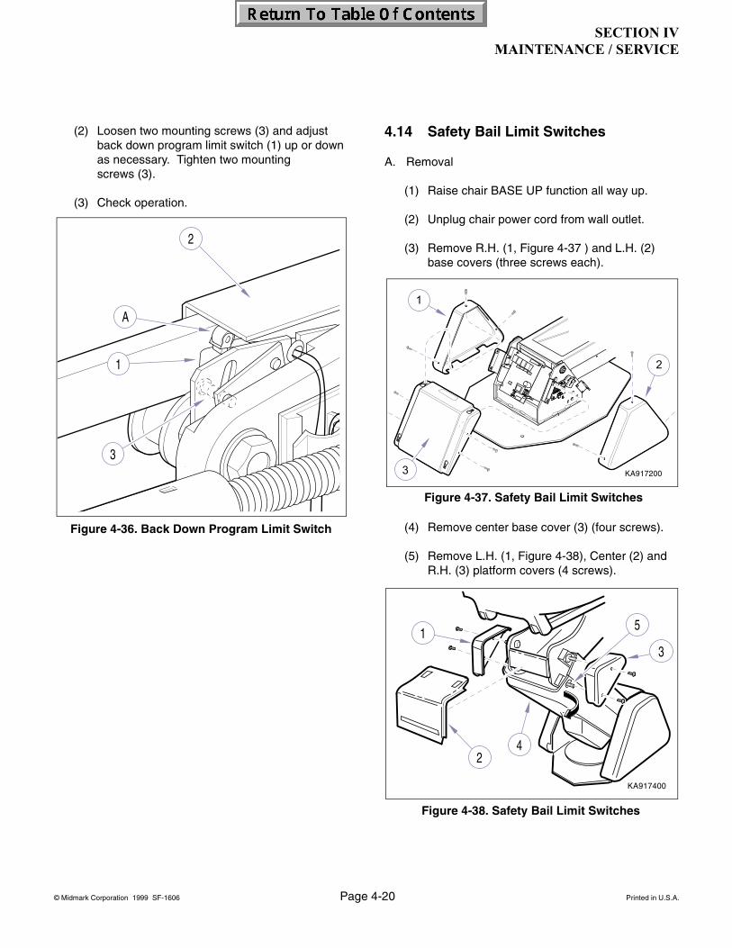
SECTION IVMAINTENANCE / SERVICE
© Midmark Corporation 1999 SF-1606 Page 4-20 Printed in U.S.A.
(2) Loosen two mounting screws (3) and adjust back down program limit switch (1) up or down as necessary. Tighten two mounting screws (3).
(3) Check operation.
4.14 Safety Bail Limit Switches
A. Removal
(1) Raise chair BASE UP function all way up.
(2) Unplug chair power cord from wall outlet.
(3) Remove R.H. (1, Figure 4-37 ) and L.H. (2) base covers (three screws each).
(4) Remove center base cover (3) (four screws).
(5) Remove L.H. (1, Figure 4-38), Center (2) and R.H. (3) platform covers (4 screws).
Figure 4-36. Back Down Program Limit Switch
Figure 4-37. Safety Bail Limit Switches
Figure 4-38. Safety Bail Limit Switches
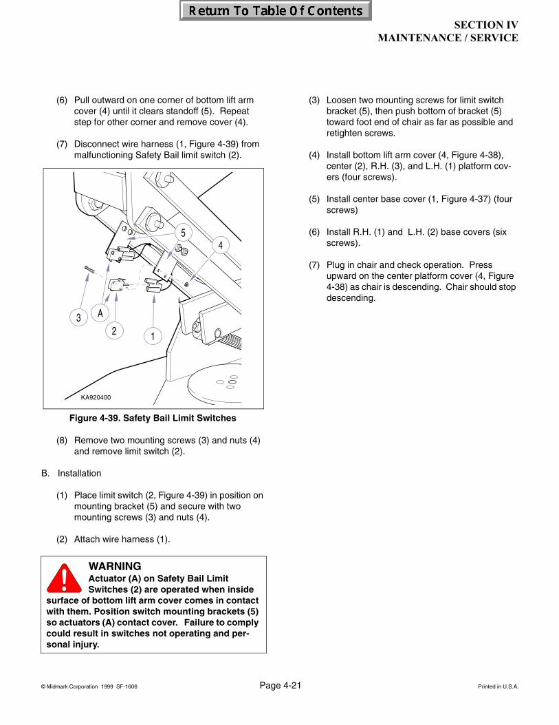
SECTION IVMAINTENANCE / SERVICE
© Midmark Corporation 1999 SF-1606 Page 4-21 Printed in U.S.A.
(6) Pull outward on one corner of bottom lift arm cover (4) until it clears standoff (5). Repeat step for other corner and remove cover (4).
(7) Disconnect wire harness (1, Figure 4-39) from malfunctioning Safety Bail limit switch (2).
(8) Remove two mounting screws (3) and nuts (4) and remove limit switch (2).
B. Installation
(1) Place limit switch (2, Figure 4-39) in position on mounting bracket (5) and secure with two mounting screws (3) and nuts (4).
(2) Attach wire harness (1).
(3) Loosen two mounting screws for limit switch bracket (5), then push bottom of bracket (5) toward foot end of chair as far as possible and retighten screws.
(4) Install bottom lift arm cover (4, Figure 4-38), center (2), R.H. (3), and L.H. (1) platform cov-ers (four screws).
(5) Install center base cover (1, Figure 4-37) (four screws)
(6) Install R.H. (1) and L.H. (2) base covers (six screws).
(7) Plug in chair and check operation. Press upward on the center platform cover (4, Figure 4-38) as chair is descending. Chair should stop descending.
WARNINGActuator (A) on Safety Bail Limit Switches (2) are operated when inside
surface of bottom lift arm cover comes in contact with them. Position switch mounting brackets (5) so actuators (A) contact cover. Failure to comply could result in switches not operating and per-sonal injury.
Figure 4-39. Safety Bail Limit Switches

SECTION IVMAINTENANCE / SERVICE
© Midmark Corporation 1999 SF-1606 Page 4-22 Printed in U.S.A.
4.15 Membrane Switch Panel (Biltmore Classic only)
A. Removal
(1) Unplug chair power cord.
(2) Remove back upholstery (refer to para 4.2).
(3) Disconnect wire harness (1, Figure 4-40) from membrane switch panel (2).
(4) Peel membrane switch (2) off bezel (3).
B. Installation
(1) After removing protective backing from mem-brane switch, place switch in position on bezel (3, Figure 4-40) and press firmly to adhere switch to bezel.
(2) Connect wire harness (1) to membrane switch panel (2).
(3) Install back upholstery.
(4) Plug chair power cord into outlet and check operation.
4.16 Manual Footswitch
A. Removal
(1) Unplug chair power cord.
(2) Remove five screws (1, Figure 4-41), base plate (2), and insulation (3) from footswitch housing (4).
(3) Remove two nuts (5) and actuator (6) from two studs (7).
(4) Remove footswitch (8); then tag and disconnect wires (9) from footswitch (8).
B. Installation
(1) Connect wires (9, Figure 4-41) to terminals of footswitch (8).
Figure 4-40. Membrane Switch Panel
Figure 4-41. Manual Footswitch
Rev. 3/03
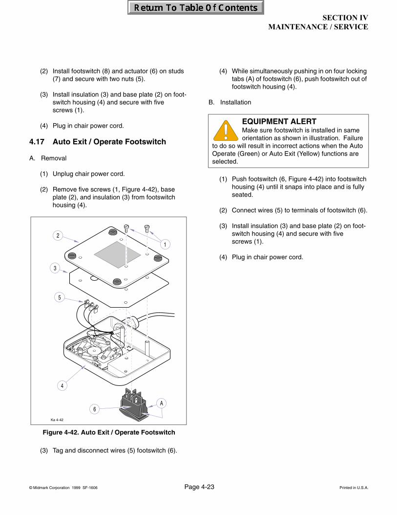
SECTION IVMAINTENANCE / SERVICE
© Midmark Corporation 1999 SF-1606 Page 4-23 Printed in U.S.A.
(2) Install footswitch (8) and actuator (6) on studs (7) and secure with two nuts (5).
(3) Install insulation (3) and base plate (2) on foot-switch housing (4) and secure with five screws (1).
(4) Plug in chair power cord.
4.17 Auto Exit / Operate Footswitch
A. Removal
(1) Unplug chair power cord.
(2) Remove five screws (1, Figure 4-42), base plate (2), and insulation (3) from footswitch housing (4).
(3) Tag and disconnect wires (5) footswitch (6).
(4) While simultaneously pushing in on four locking tabs (A) of footswitch (6), push footswitch out of footswitch housing (4).
B. Installation
(1) Push footswitch (6, Figure 4-42) into footswitch housing (4) until it snaps into place and is fully seated.
(2) Connect wires (5) to terminals of footswitch (6).
(3) Install insulation (3) and base plate (2) on foot-switch housing (4) and secure with five screws (1).
(4) Plug in chair power cord.
Figure 4-42. Auto Exit / Operate Footswitch
EQUIPMENT ALERTMake sure footswitch is installed in same orientation as shown in illustration. Failure
to do so will result in incorrect actions when the Auto Operate (Green) or Auto Exit (Yellow) functions are selected.

SECTION IVMAINTENANCE / SERVICE
© Midmark Corporation 1999 SF-1606 Page 4-24 Printed in U.S.A.
4.18 Rotational Brake (Biltmore Classic only)
A. Removal
(1) Raise Base Up function all way up.
(2) Unplug chair power cord.
(3) Remove R.H. base cover (1, Figure 4-43) (three screws).
(4) Place Brake lever (2) in Unlocked position.
(5) Remove disc lock (3), four screws.
(6) Remove brake block assembly (4).
(7) Unscrew brake block (1,Figure 4-43) from lock stud (2).
(8) Remove two set screws (3) from brake block (1).
B. Installation
(1) Install two set screws (3, Figure 4-44)) in brake block (1).
(2) Assemble brake block (1, Figure 4-44) and lock stud (5).
(3) Insert brake block assembly (1, Figure 4-45) into hole of upright housing assembly (2).
(4) Install disc lock (3) and secure with four screws.
Figure 4-43. Rotational Brake
NOTEInspect nylon tipped set screws (3, Figure 4-44). If worn or damaged replace screws.
NOTEWhen assembling brake block (1, Figure 4-44), posi-tion jam nut (4) on lock stud (5) so there is approxi-mately 1/4" to 5/16" distance between jam nut (4) and face of hex (A) on lock stud (5).
Figure 4-44. Rotational Brake
Rev. 3/03
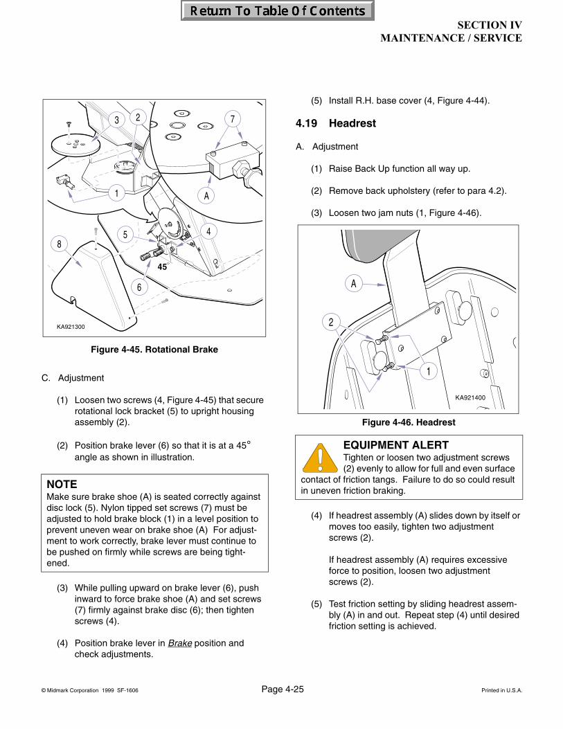
SECTION IVMAINTENANCE / SERVICE
© Midmark Corporation 1999 SF-1606 Page 4-25 Printed in U.S.A.
C. Adjustment
(1) Loosen two screws (4, Figure 4-45) that secure rotational lock bracket (5) to upright housing assembly (2).
(2) Position brake lever (6) so that it is at a 45° angle as shown in illustration.
(3) While pulling upward on brake lever (6), push inward to force brake shoe (A) and set screws (7) firmly against brake disc (6); then tighten screws (4).
(4) Position brake lever in Brake position and check adjustments.
(5) Install R.H. base cover (4, Figure 4-44).
4.19 Headrest
A. Adjustment
(1) Raise Back Up function all way up.
(2) Remove back upholstery (refer to para 4.2).
(3) Loosen two jam nuts (1, Figure 4-46).
(4) If headrest assembly (A) slides down by itself or moves too easily, tighten two adjustment screws (2).
If headrest assembly (A) requires excessive force to position, loosen two adjustment screws (2).
(5) Test friction setting by sliding headrest assem-bly (A) in and out. Repeat step (4) until desired friction setting is achieved.
NOTEMake sure brake shoe (A) is seated correctly against disc lock (5). Nylon tipped set screws (7) must be adjusted to hold brake block (1) in a level position to prevent uneven wear on brake shoe (A) For adjust-ment to work correctly, brake lever must continue to be pushed on firmly while screws are being tight-ened.
Figure 4-45. Rotational Brake
EQUIPMENT ALERTTighten or loosen two adjustment screws (2) evenly to allow for full and even surface
contact of friction tangs. Failure to do so could result in uneven friction braking.
Figure 4-46. Headrest

SECTION IVMAINTENANCE / SERVICE
© Midmark Corporation 1999 SF-1606 Page 4-26 Printed in U.S.A.
(6) While holding adjustment screws (2) with a wrench, tighten jam nuts (1).
(7) Install back upholstery.

SECTION VSCHEMATICS AND DIAGRAMS
© Midmark Corporation 1999 SF-1606 Page 5-1 Printed in U.S.A.
nc
DA3240i
nc
nc
nc
cc
c
c
c c
nc
c
nc
c
nc
5 1
81
111
J5
J4J2J3J1
nc
nc
c
c
nc
SafetyBail Switch
SafetyBail Switchc
nc
5.1 Electrical Schematics / Wiring Diagrams
Figure 5-1 illustrates the wiring connections between
the components in the 120 VAC chair. Figures 5-2 and 5-3 illustrate the main PC board plug connectors and related circuitry. Figure 5-4 thru 5-6 show the main PC board,TB1 terminal board, and related components.
Figure 5-1. Wiring Diagram Biltmore Classic / *Concept LR Classic Dental Chair (120 VAC Units) Thru Serial Number V160530
J2 Pin Out - Chair ControlsPin Color Function1 Black 12 Volt DC
2 Blue Auto Exit3 Brown Auto Operate4 Green Back Up
5 Orange Back Down6 Red Base Up7 White Base Down
8 Yellow Light Switch
J3 Pin Out - Foot ControlPin Color Function1 Brown 12 Volt DC
2 Blue Auto Exit3 Orange Auto Operate4 Green Back Up
5 Black Back Down6 Red Base Up7 White Base Down
8 - Open
J4 Pin Out for Program, Oper-ation and Limit Switches
Pin Color Function1 Red 800 to 860 Ohms to
Ground2 Black 800 to 860 Ohms to
Ground Base Up Pro-gram Operation Switch Closed
3 Brown 800 to 860 Ohms to Ground
4 Green 800 to 860 Ohms to Ground Back Down Pro-gram Operation Switch Closed
5 White 12 VDC from Back Up Limit Switch
6 Red 12 VDC out to Back Up Limit Switch
7 Black Return 12 VDC from Back Up Limit Switch
8 Green Return 12 VDC from Base Down Limit Switch
9 Red 12 VDC out to Base Up and Base Down Limit Switches
10 Black Return 12 VDC from Base Up Limit Switch
J5Pin Color1 Red2 White3 Black
4 White5 Blue6 Green
7 Black8 Black
J1Pin Color1 White2 Black3 White
4 Black5 Green/
Yellow
SECTION V
Rev. 6/11

SECTION VSCHEMATICS AND DIAGRAMS
© Midmark Corporation 1999 SF-1606 Page 5-2 Printed in U.S.A.
DA3241i
Motor Fuse10 A, 250 V, Type F, Fast-Acting
ncc c
nc
c
nc
c
nc
81
111
Spare1/2 AmpFuse
Spare Fuse10 Amp
J5
J4J2J3J1
Back
Motor
151884Top Motor
Cable Assy.
Back DownProgram
Switch
Back Up
Limit Switch
Terminal Block
& Mounting Plate
Base
Motor
Foot Control
Base Motor
Capacitor
Chair Control PC Board
c
Line InputFuse
1/2 A. 250 V.
c
nc
Safety
Bail Switch
Safety
Bail Switchc
nc
151293Safety Limit
Harness
nc
On / OffLight
Fuse F410 A, 250 VAC
Type FFast-Acting
WHBK
GN/YL
WH
WH
BK
GN/YL
WH BK
BKWH
BK
120 VAC60 HZ8 AMP
5 134 2
nc
nc
c
c
c
cnc
nc
WHBK
Rev. 6/11
Figure 5-2. Wiring Diagram Biltmore Classic / *Concept L/R Classic Dental Chair (120 VAC Units)From Serial Number V160531 thru V456962
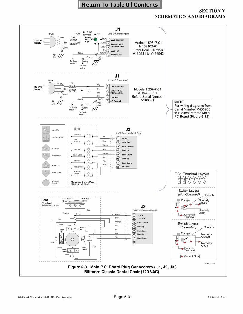
SECTION VSCHEMATICS AND DIAGRAMS
© Midmark Corporation 1999 SF-1606 Page 5-3 Printed in U.S.A.
KA913202
Red
Brown
Blk
Wht
Brown
Grn
Brown
Blk
Blue
Brown
Grn
Orange
Red
Wht
Back Down
Back Up
Base Down
Blue
Orange
C
NOC
NO
Brown
Brown
Grn
Wht
Red
Base Up
FootControl
J3(To 12 VDC Foot Control Switch)
CNO
C NO
(View from bottom side)CNO NO
Auto ExitYellow
Auto OperateGreen
Auto Operate
12 VDC
Auto Exit
Back Down
Back Up
Base Down
Base Up
8
7
6
5
4
3
2
1
Blk
Wht
J1
Grn
Grn/yl Grn/yl
Wht
Blk
Wht
Blk
TB1
VAC Common
VAC Hot
AC Ground
120/240 VACInterface Pins
(115 VAC Power Input)
To Base Motor
Grn/yl
TB1 Grd
Plug
115 VACSupply
5
4
3
2
1
3
2
Grn/yl
To Back Motor
TB1 Grd
Models 152647-01& 153102-01
From Serial NumberV160531 to V456962
Models 152647-01& 153102-01
Before Serial NumberV160531
Blk
Wht
J1
Grn
Grn/yl Grn/yl
Wht
Blk
Wht
Blk
TB1VAC Common
VAC Hot
AC Ground
120/240 VACInterface Pins
(115 VAC Power Input)
Grn/yl
TB1 Grd
Plug
115 VACSupply
PowerOn / OffLight
WhtWht
Blk
F4 FUSE
5
4
3
2
1
3
2
TB1 Grd
To Base Motor
Grn/yl
To Back Motor
2 3 4 5 61
TB1 Terminal Layout
Switch Layout(Not Operated)
CommonTerminal
NormallyOpen
Plunger NormallyClosed
Contacts
Switch Layout(Operated)
CommonTerminal
NormallyOpen
Plunger NormallyClosed
Contacts
Current Flow
AuxiliarySwitch
AuxiliarySwitch
Auto Operate
Red
Blk
Blue
Brown
Grn
Orange
Blk
Blue
Brown
Grn
Yellow
Blk
Blue
Brown
Grn
Wht
Auto Exit
12 VDC
Base Down
Membrane Switch Pads(Right & Left Side)
Base Up
Back Down
Back Up
Auto Operate
12 VDC
Auto Exit
Back Up
Back Down
Base Down
Base Up
Auto Exit
Auto Operate
Back Up
Back Down
Base Up
Base Down
J2(12 VDC Membrane Switch Pads)
12
3
4
5
6
7
8 Auxiliary
NOTEFor wiring diagrams fromSerial Number V456963to Present refer to Main PC Board (Figure 5-12).
Figure 5-3. Main P.C. Board Plug Connectors ( J1, J2, J3 ) Biltmore Classic Dental Chair (120 VAC)
Rev. 4/06
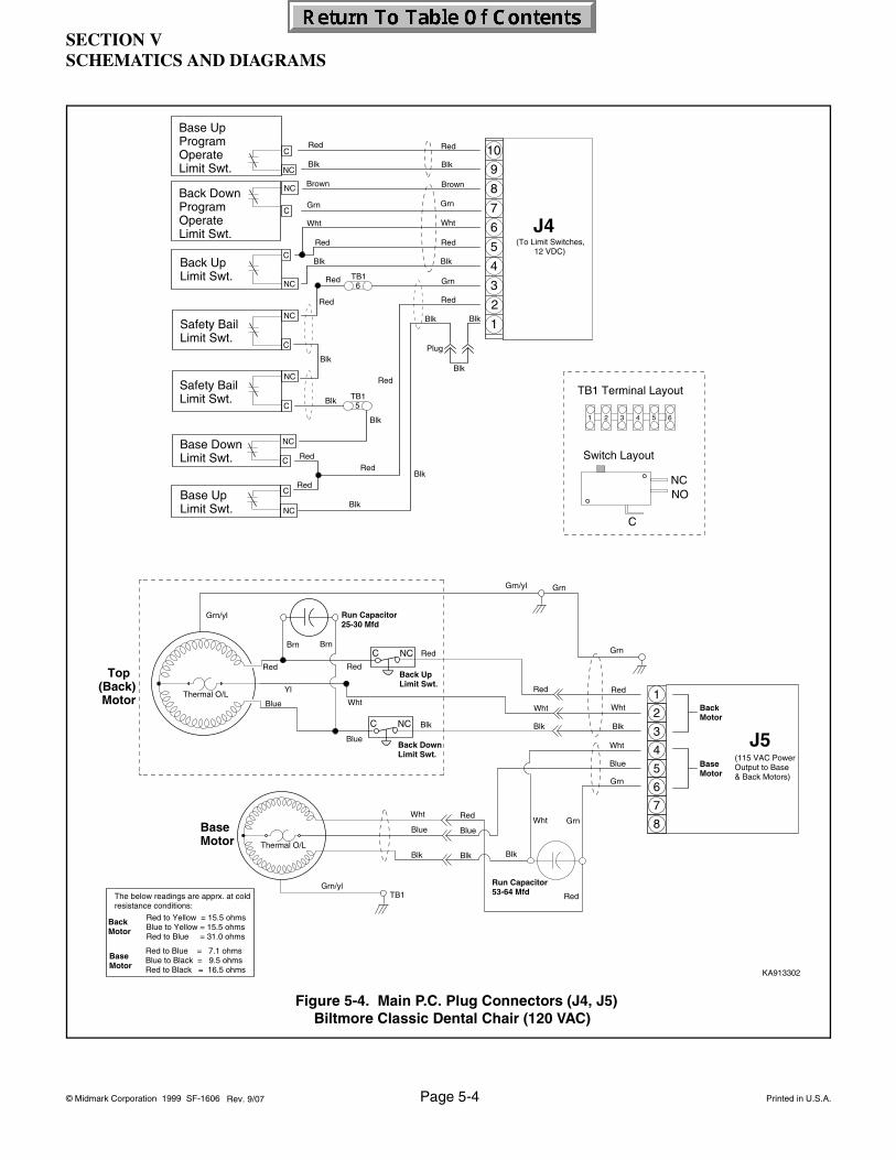
SECTION VSCHEMATICS AND DIAGRAMS
© Midmark Corporation 1999 SF-1606 Page 5-4 Printed in U.S.A.
Figure 5-4. Main P.C. Plug Connectors (J4, J5)Biltmore Classic Dental Chair (120 VAC)
KA913302
TB1 Terminal Layout
Switch Layout
C
NCNO
2 3 4 5 61
Top(Back) Motor
Wht
Yl
Red
Blue
Red
Blue
Wht
Red
Red
Wht
Blk
Wht
Blue
Grn
8
7
6
5
4
3
2
1Red
Wht
Blk
GrnGrn/yl
BrnBrn
Run Capacitor25-30 Mfd
Grn
Blue
Blk Blk
BlueWht
Red
Blk
Base Motor
Run Capacitor53-64 Mfd
Blk
Back DownLimit Swt.
Back UpLimit Swt.
NCC
NCC
Grn/yl
RedGrn
Back Motor
Base Motor
Grn/ylTB1
Thermal O/L
J5(115 VAC Power Output to Base & Back Motors)
Thermal O/L
Back Motor
Base Motor
Red to Yellow = 15.5 ohmsBlue to Yellow = 15.5 ohmsRed to Blue = 31.0 ohms
Red to Blue = 7.1 ohmsBlue to Black = 9.5 ohmsRed to Black = 16.5 ohms
The below readings are apprx. at cold resistance conditions:
Brown
Grn
Blk
Red
Red
Wht
Blk
BlkBlk
Blk
Red
Blk
RedRed
Red
GrnRed
Red
Blk
Blk
Red
Blk
Brown
Grn
Wht
Red
Blk
Red
(To Limit Switches, 12 VDC)
3
4
5
6
7
8
9
10
1
2
J4
6TB1
Base UpProgramOperate Limit Swt.
Base UpLimit Swt. NC
C
Blk
Back DownProgramOperateLimit Swt.
NC
C
Safety BailLimit Swt.
C
NC
Safety BailLimit Swt.
C
NC
C
Base DownLimit Swt.
NC
5TB1
C
NC
C
NC
Back UpLimit Swt.
Blk
Plug
Rev. 9/07
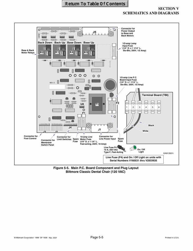
SECTION VSCHEMATICS AND DIAGRAMS
© Midmark Corporation 1999 SF-1606 Page 5-5 Printed in U.S.A.
KA913501i
Spare Fuse
10-amp LineMotor Fuse(1/4" D. x 1 1/4" L.Fast-acting, 250V, 10 Amp)
1/2-amp Line P.C. Board Input Fuse(1/4" D. x 1 1/14" L. Slo-Blo, 250V, 1/2 Amp)
Back Down Back Up Base UpBase Down
Connector forMembraneSwitch Panel
Black
White
Terminal Board (TBI)
K4K1K2 K3
J1J2J3
J4
F1
F2U8
NO
Co
m
Co
m
Co
m
Co
m
NO
NO
NO
Connector forLimit Switches Spare
Fuse
Connector forFoot Control
Connector forPower Outputto Base and Back Motors
Connector for Line Power Input
Base & BackMotor Relays
T1
1/2-amp Lamp Input Fuse(1/4" D. x 1 1/14" L. Slo-Blo, 250V, 1/2 Amp)
Line Fuse F410 A, 250 VACType F, Fast-Acting
On / OffLight
Line Fuse (F4) and On / Off Light on units with Serial Numbers V160531 thru V2933935
Rev. 8/07
Figure 5-5. Main P.C. Board Component and Plug LayoutBiltmore Classic Dental Chair (120 VAC)

SECTION VSCHEMATICS AND DIAGRAMS
© Midmark Corporation 1999 SF-1606 Page 5-6 Printed in U.S.A.Rev. 4/06
Figure 5-6. 115 VAC Motor Circuit

SECTION VSCHEMATICS AND DIAGRAMS
© Midmark Corporation 1999 SF-1606 Page 5-7 Printed in U.S.A.
Figure 5-7. 12 VDC Control Circuit (120 VAC Supply).
Rev. 4/06

SECTION VSCHEMATICS AND DIAGRAMS
© Midmark Corporation 1999 SF-1606 Page 5-8 Printed in U.S.A.
nc
DA3240i
nc
nc
nc
cc
c
c
c c
nc
c
nc
c
nc
5 1
81
111
J5
J4J2J3J1
nc
nc
c
c
nc
SafetyBail Switch
SafetyBail Switchc
nc
J2 Pin Out for Membrane Switch
Pin Color Function1 Black 12 Volt DC
2 Blue Auto Exit3 Brown Auto Operate4 Green Back Up
5 Orange Back Down6 Red Base Up
7 White Base Down8 Yellow Light Switch
J3 Pin Out for Foot Switch
Pin Color Function1 Brown 12 Volt DC2 Blue Auto Exit
3 Orange Auto Operate4 Green Back Up5 Black Back Down
6 Red Base Up7 White Base Down8 - Open
J4 Pin Out for Program, Oper-ation and Limit Switches
Pin Color Function1 Red 800 to 860 Ohms to
Ground2 Black 800 to 860 Ohms to
Ground Base Up Pro-gram Operation Switch Closed
3 Brown 800 to 860 Ohms to Ground
4 Green 800 to 860 Ohms to Ground Back Down Pro-gram Operation Switch Closed
5 White 12 VDC from Back Up Limit Switch
6 Red 12 VDC out to Back Up Limit Switch
7 Black Return 12 VDC from Back Up Limit Switch
8 Green Return 12 VDC from Base Down Limit Switch
9 Red 12 VDC out to Base Up and Base Down Limit Switches
10 Black Return 12 VDC from Base Up Limit Switch
J1Pin Color1 White2 Black3 White
4 Black5 Green/
Yellow
J5Pin Color1 Red2 White3 Black
4 White5 Blue6 Green
7 Black8 Black
Figure 5-8. Wiring Diagram Biltmore Classic / *Concept L/R Classic Dental Chair (240 VAC Units) From Serial Number V160531 thru V456962
Rev. 6/11
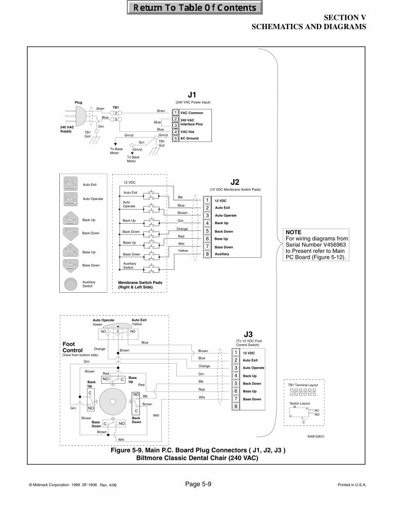
SECTION VSCHEMATICS AND DIAGRAMS
© Midmark Corporation 1999 SF-1606 Page 5-9 Printed in U.S.A.
2 3 4 5 61
TB1 Terminal Layout
Switch Layout
C
NCNO
AuxiliarySwitch
AuxiliarySwitch
Auto Operate
Red
Blk
Blue
Brown
Grn
Orange
Blk
Blue
Brown
Grn
Yellow
Blk
Blue
Brown
Grn
Wht
Auto Exit
12 VDC
Base Down
Membrane Switch Pads(Right & Left Side)
Base Up
Back Down
Back Up
Auxiliary
Auto Operate
12 VDC
Auto Exit
Back Up
Back Down
Base Down
Base Up
8
7
6
5
4
3
2
1
Auto Exit
Auto Operate
Back Up
Back Down
Base Up
Base Down
J2(12 VDC Membrane Switch Pads)
KA915301i
Brwn
Blue
J1
Grn
Grn/yl Grn/yl
Brwn
Blue
3
2
TB1
5
4
3
2
1 VAC Common
VAC Hot
AC Ground
240 VACInterface Pins
(240 VAC Power Input)
To Base Motor
Grn/yl
To Back Motor
TB1 Grd
Grn
TB1 Grd
Plug
Blue
240 VACSupply
Red
Brown
Blk
Wht
Brown
Grn
Brown
Blk
Blue
Brown
Grn
Orange
Red
Wht
Back Down
Back Up
Base Down
Blue
Orange
C
NOC
NO
Brown
Brown
Grn
Wht
Red
Base Up
FootControl
J3(To 12 VDC Foot Control Switch)
Auto Operate
12 VDC
Auto Exit
Back Down
Back Up
Base Down
Base Up
8
7
6
5
4
3
2
1
CNO
C NO
(View from bottom side)
CNO NO
Auto ExitYellow
Auto OperateGreen
NOTEFor wiring diagrams fromSerial Number V456963to Present refer to Main PC Board (Figure 5-12).
Figure 5-9. Main P.C. Board Plug Connectors ( J1, J2, J3 )Biltmore Classic Dental Chair (240 VAC)
Rev. 4/06

SECTION VSCHEMATICS AND DIAGRAMS
© Midmark Corporation 1999 SF-1606 Page 5-10 Printed in U.S.A.
Figure 5-10. Main P.C. Plug Connectors (J4, J5)Biltmore Classic Dental Chair (240 VAC)
KA915401
TB1 Terminal Layout
Switch Layout
C
NCNO
2 3 4 5 61
Brown
Grn
Blk
Red
Red
Wht
Blk
BlkBlk
Blk
Red
Blk
RedRed
Red
GrnRed
Red
Blk
Blk
Red
Blk
Brown
Grn
Wht
Red
Blk
Red
(To Limit Switches, 12 VDC)
8
7
6
5
4
3
2
1
10
9
J4
6TB1
Base UpProgramOperate Limit Swt.
Base UpLimit Swt. NC
C
Blk
Back DownProgramOperateLimit Swt.
NC
C
Safety BailLimit Swt.
C
NC
Safety BailLimit Swt.
C
NC
C
Base DownLimit Swt.
NC
5TB1
C
NC
C
NC
Back UpLimit Swt.
Blk
Plug
Brown
Top(Back) Motor Yl
Red
Blue
Red
Blue
Wht
Red
Red
Wht
Blk
Wht
Blue
Grn
8
7
6
5
4
3
2
1Red
Wht
Blk
GrnGrn/yl
BrnBrn
Run Capacitor5.0 Mfd
Grn
Blue
Blk Blk
BlueWht
Red
Blk
Base Motor
Run Capacitor12.5 Mfd
Blk
Back DownLimit Swt.
Back UpLimit Swt.
NCC
NCC
Grn/yl
RedGrn
Back Motor
Base Motor
Grn/ylTB1
Thermal O/L
Thermal O/L
J5(240VAC Power Output to Base & Back Motors)
Back Motor
Base Motor
Red to Yellow = 61.0 ohmsBlue to Yellow = 62.0 ohmsRed to Blue = 122.0 ohms
Brown to Blue = 27.0 ohmsBlue to Black = 47.4 ohmsBrown to Black = 74.5 ohms
Rev. 9/07
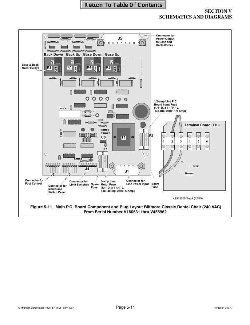
SECTION VSCHEMATICS AND DIAGRAMS
© Midmark Corporation 1999 SF-1606 Page 5-11 Printed in U.S.A.
Figure 5-11. Main P.C. Board Component and Plug Layout Biltmore Classic Dental Chair (240 VAC)From Serial Number V160531 thru V456962
Rev. 9/07

SECTION VSCHEMATICS AND DIAGRAMS
© Midmark Corporation 1999 SF-1606 Page 5-12 Printed in U.S.A.
015-2140-01 120VAC015-2140-03 240VAC
J1
F2
F3
T1TRANSFORMER
F7
TP3
TP1GND
J8
D1
D5
D7
D9
TP4
MP1
J7
TP2
115V = 8A230V = 4A
115V = 125mA 230V = 50 mA
115V = 315 mA230V = 160 mA
115V = 4A230V = 2A
115V = 4A230V = 2A
D3
F6 F1
L1SIGNAL
TRANSFORMER
F5
Back Motor Fuse
Base Motor Fuse
Light Fuse
ContactsOpen
BACK UP K1
ContactsOpen
BACK DOWN K2
BASE UP K4Contacts
Open
ContactsOpen
LAMP K5
BASE DOWN K3
ContactsOpen
LED
LED
LED
LED
LED
1
1
+12V
+ 5V
1
SUPPLYLINE FUSES
TP5 TP7
TP8
TP9
TP10TP6
D12
DiagnosticsLED
ProgrammingHeader
ProgrammingClock
RS232Plug
+12V
Line Voltage
FOOT CONTROLSWITCH
WHITE
J3
8 1234567
FusesType TSlo-Blo
FusesType TSlo-Blo
FusesType TSlo-Blo
L2 L1
T1TRANSFORMER
FusesType TSlo-Blo
WHITE
+12VLIMIT SWITCH
J4
8 1234567910
+12VMEMBRANE SWITCH J2
8 1234567
1
J5Line VoltageLine Voltage
151884Harness
151885Harness
REDWH
BK
BACKUP
COM.
BACKDOWN
COM.
BASEUP
BASEDOWN
LAMPCOM. ON
TOBACK
MOTOR
TOBASE
MOTOR
BK BKWH
BLGN
152210Harness
3 4 5 6 8721
TOLIGHTTRANSFORMER
Fuse
F1 015-0346-37015-0346-14
115 VAC 230 VAC
F2, F3F5
F6, F7
015-0346-34015-0346-01015-0346-38015-0346-39015-0346-01015-0346-19
015-2140-01
PCB
015-2140-03
151383Harness
BLACK
J4 ConnectorPROGRAM, OPERATION, & LIMIT SWITCHES
4
8
6
7
5 RED
WHITE
GREEN3
2
BROWN
9
10
1 BLACK Return 12 VDC From Base Up
12 VDC To Base Up & Down (Common)
Return 12 VDC From Base Down
Return 12 VDC From Back Up
12 VDC to Back Up Limit Switch (Common)
Jumper to Pin 5
Return 12 VDC from Back Down Program Limit Swt.
12 VDC To Base Down Program Limit Switch (Common)
GREEN
Return 12 VDC From Base Up Program Limit Switch.
RED
BLACK
12 VDC To Base Up Program Limit Switch (Common).
FUNCTIONCOLORPIN
RED
BLACK
To SafetyBail LimitSwitches151293
Chair TerminalBlock &
Mounting Plate
To SupplyPower
To J4 on PC Board151383
Base UpBase DownLimit Switches
PowerOn / Off
Light
015-2155-00Power Harness
BR
BL
G/YBRBL
BK R
G
G/Y
BLBR
BL
BR
5 1J1
Wiring Diagram for Knight Chairs Models:152375-01, 152267-01, 152647-01, 152723-01, 153039-01, 153085-01, 153102-01, 153335-01, 152192-01
From Serial V456963 to Present
6 RED BASE UP5 BLACK
PIN COLOR
BACK DOWN
FUNCTION
J3 ConnectorFOOT SWITCH
4 GREEN BACK UP
8 OPEN-7 WHITE BASE DOWN
AUTO OPERATE3 ORANGE2 BLUE AUTO EXIT1 BROWN 12 VOLT DC
TP1 to TP2
Test Point on PCB Checks:
TEST POINTS (TP)
12 VDC Supply for PCB5 VDC to Base Up Program Limit5 VDC to Back Down Program Limit5 VDC to Back Down Limit5 VDC to Back Up Limit5 VDC to Base Down Limit5 VDC to Base Up Limit
TP1 to TP5TP1 to TP6TP1 to TP7TP1 to TP8TP1 to TP9TP1 to TP10
J1 Plug Pins 3 - 4 Supply Line Voltage VAC
Supply Voltage 5 VDCTP1 to TP3
9/12
Figure 5-12. Main P.C. Board Component and Plug Layout Biltmore Classic Dental Chair (120 & 240 VAC)From Serial Number V456963 to Present

SECTION VSCHEMATICS AND DIAGRAMS
© Midmark Corporation 1999 SF-1606 Page 5-13 Printed in U.S.A.
DA186700i
9/07
Figure 5-13. Wire Harness Diagram ChartFrom Serial Number V456963 to Present

SECTION VSCHEMATICS AND DIAGRAMS
© Midmark Corporation 1999 SF-1606 Page 5-14 Printed in U.S.A.
Figure 5-12. 240 VAC Motor Circuit
Rev. 4/06
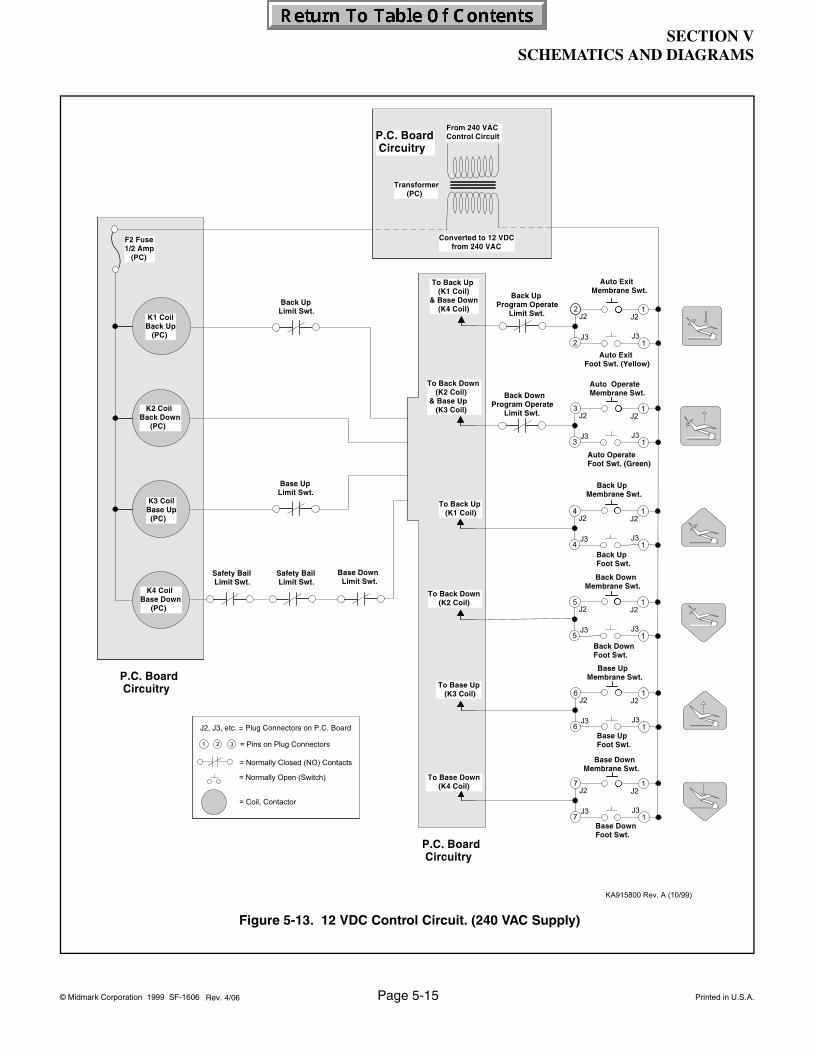
SECTION VSCHEMATICS AND DIAGRAMS
© Midmark Corporation 1999 SF-1606 Page 5-15 Printed in U.S.A.
Figure 5-13. 12 VDC Control Circuit. (240 VAC Supply)
Rev. 4/06
SECTION VIPARTS LIST
© Midmark Corporation 2000 SF-1606 Printed in U.S.A.
Always Specify Model & Serial Number
SECTION VIPARTS LIST
6.1 Introduction
The illustrated parts list provides information for identify-ing and ordering the parts necessary to maintain the unit in peak operating condition. Refer to paragraph 1.5 for parts ordering information.
6.2 Description of Columns
The Item column of the parts list gives a component its own unique number. The same number is given to the component in the parts illustration. This allows a part number of a component to be found if the technician can visually spot the part on the illustration. The techni-cian simply finds the component in question on the illus-tration and notes the item number of that component. Then, he finds that item number in the parts list. The row corresponding to the item number gives the techni-cian the part number, a description of the component, and quantity of parts per subassembly. Also, if a part number is known, the location of that component can be determined by looking for the item number of the com-ponent on the illustration.
The Part No. column lists the MIDMARK part number for that component.
The Description column provides a physical description of the component.
The Qty. column lists the number of units of a particular component required for the subassembly. The letters “AR” denote “as required” when quantities of a particu-lar component cannot be determined, such as: adhe-sive.
Bullets { • } in the Part No. column and the Description column show the indenture level of a component. If a component does not have a bullet, it is a main compo-nent of that illustration. If a component has a bullet, it is a subcomponent of the next component listed higher in the parts list than itself that does not have a bullet. Like-wise, if a component has two bullets, it is a subcompo-nent of the next component listed higher in the parts list than itself that has only one bullet.
6.3 Torque Specifications and Important Assembly Notes
When specific assembly torque specifications, mea-surements, or procedures have been identified, by our engineering department, as required to assure proper function of the unit, those torque specifications mea-surements, and procedures will be noted on the parts illustrations. Adherence to these requirements is essen-tial.
Page 6-1
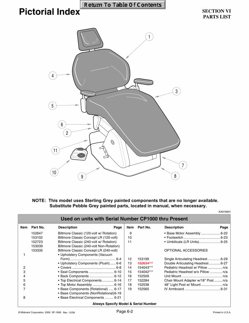
SECTION VIPARTS LIST
Always Specify Model & Serial Number
© Midmark Corporation 2000 SF-1606 Printed in U.S.A.Page 6-2Rev. 12/09
Pictorial Index
KA916601
Used on units with Serial Number CP1000 thru Present
Item Part No. Description Page Item Part No. Description Page
152647 Biltmore Classic (120-volt w/ Rotation)153102 Biltmore Classic Concept LR (120-volt)152723 Biltmore Classic (240-volt w/ Rotation)153039 Biltmore Classic (240-volt Non-Rotation)153335 Biltmore Classic Concept LR (240-volt)
1 • Upholstery Components (VacuumForm) ............................................... 6-4
• Upholstery Components (Plush)...... 6-62 • Covers ............................................. 6-83 • Seat Components .......................... 6-104 • Back Components ......................... 6-125 • Top Electrical Components ............ 6-146 • Top Motor Assembly ...................... 6-167 • Base Components (Rotational) ..... 6-17
• Base Components (NonRotational)6-198 • Base Electrical Components ......... 6-21
9 • Base Motor Assembly ....................6-2210 • Footswitch ......................................6-2311 • Umbilicals (LR Units)......................6-25
OPTIONAL ACCESSORIES
12 153199 Single Articulating Headrest .............6-2913 152634*** Double Articulating Headrest ............6-2714 154043*** Pediatric Headrest w/ Pillow ............... n/a15 154042*** Pediatric Headrest w/o Pillow ............. n/a16 152509 Unit Mount .......................................... n/a17 152284 Chair Mount Adapter w/18" Post......... n/a18 152538 48" Light Post w/ Mount ...................... n/a19 152565 IV Armboard .....................................6-31
NOTE: This model uses Sterling Grey painted components that are no longer available. Substitute Pebble Grey painted parts, located in manual, when necessary.
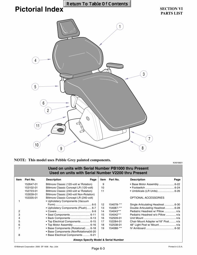
SECTION VIPARTS LIST
© Midmark Corporation 2000 SF-1606 Printed in U.S.A.
Always Specify Model & Serial Number
Page 6-3Rev. 2/04
Pictorial Index
KA916601
Used on units with Serial Number PB1000 thru PresentUsed on units with Serial Number V2200 thru Present
Item Part No. Description Page Item Part No. Description Page
152647-01 Biltmore Classic (120-volt w/ Rotation)153102-01 Biltmore Classic Concept LR (120-volt)152723-01 Biltmore Classic (240-volt w/ Rotation)153039-01 Biltmore Classic (240-volt Non-Rotation)153335-01 Biltmore Classic Concept LR (240-volt)
1 • Upholstery Components (VacuumForm) ............................................... 6-5
• Upholstery Components (Plush)...... 6-72 • Covers ............................................. 6-93 • Seat Components .......................... 6-114 • Back Components ......................... 6-135 • Top Electrical Components ............ 6-156 • Top Motor Assembly ...................... 6-167 • Base Components (Rotational) ..... 6-18
• Base Components (NonRotational)6-208 • Base Electrical Components ......... 6-21
9 • Base Motor Assembly ....................6-2210 • Footswitch ......................................6-2411 • Umbilicals (LR Units)......................6-26
OPTIONAL ACCESSORIES
12 154078-*** Single Articulating Headrest .............6-3013 154087-*** Double Articulating Headrest ............6-2814 154043*** Pediatric Headrest w/ Pillow ............... n/a15 154042*** Pediatric Headrest w/o Pillow ............. n/a16 152509-01 Unit Mount .......................................... n/a17 152284-01 Chair Mount Adapter w/18" Post......... n/a18 152538-01 48" Light Post w/ Mount ...................... n/a19 154088-*** IV Armboard .....................................6-32
NOTE: This model uses Pebble Grey painted components.

SECTION VIPARTS LIST
Always Specify Model & Serial Number
© Midmark Corporation 2000 SF-1606 Printed in U.S.A.Page 6-4Rev. 12/09
Upholstery Components (Vacuum Form)
Item Part No. Description Qty Item Part No. Description Qty
154033xxx Vacuum Form Upholstery Kit (IncludesItems 1 thru 22) ..................................... 1
1 • 152653xxx • Back Rest Upholstery ......................... 12 • 152636Vxx • Arm Rest Cushion............................... 23 • 152637 • RH Arm Rest Assy (Includes Items ... 4
thru 12) (Shown Exploded) ................. 1• 152638 • LH Arm Rest Assy (Includes Items .... 4
thru 12) ............................................... 14 • • (N.L.A.) • • Arm Rest Support (1 per Arm Rest) 25 • • 122006-2 • • Plunger Housing (1 per Arm Rest) ... 26 • • 121997 • • Spring (1 per Arm Rest) ................... 27 • • 121996-3 • • Plunger (1 per Arm Rest) ................. 28 • • 122007-50 • • Stop Plate (1 per Arm Rest) ............. 29 • • 120950 • • Screw (1 per Arm Rest).................... 2
10 • • 121954-50 • • Retainer Disk (1 per Arm Rest) ........ 211 • • 119034 • • Thrust Race (2 per Arm Rest) .......... 412 • • 152674-50 • • Support Hub (1 per Arm Rest) ......... 2
13 • 122943 • Foot Rest Cover (velcro- shown) .........1148503 Foot Rest Cover (elastic- not shown) ..1
14 • 152654xxx • Seat Rest Assy (Includes Items 15 thru 20) ................................................1
15 • • 121919-50 • • RH Roller Bracket .............................116 • •121077 • • Screw ................................................617 • • 121920-50 • • LH Roller Bracket ..............................118 • • 061-0041-00 • • Law Label..........................................119 • • 300067 • • CA Compliance Label .......................120 • • 300116 • • Caution Label....................................121 • 118796 • Screw...................................................422 • 120718 • Screw...................................................423 154029xxx Head Rest (Includes Items 24 thru 27) ..124 • 152456xxx • Back Board ..........................................125 • 152457xxx • Magnetic Pillow....................................126 • 121536 • Cover, Back [Sterling]](Not Shown) ....127 • 275184 • Tape, Foam (Not Shown).................2 ft.
(N.L.A. denotes “No longer Available”)
KA915700NOTE: Substitute Pebble Grey painted parts, located in manual, when necessary.

SECTION VIPARTS LIST
© Midmark Corporation 2000 SF-1606 Printed in U.S.A.
Always Specify Model & Serial Number
Page 6-5
Upholstery Components (Vacuum Form)
Item Part No. Description Qty Item Part No. Description Qty
154075-xxx Vacuum Form Upholstery Kit (IncludesItems 1 thru 22)......................................1
1 • 154093-xxx • Back Rest Upholstery ..........................12 • 152636V-xxx • Arm Rest Cushion ...............................23 • 152637-01 • RH Arm Rest Assy (Includes Items 4
thru 12) (Shown Exploded)..................1• 152638-01 • LH Arm Rest Assy (Includes Items 4
thru 12) ................................................14 • • 152675-50 • • Arm Rest Support (1 per Arm Rest) 25 • • 122006-2 • • Plunger Housing (1 per Arm Rest)....26 • • 121997 • • Spring (1 per Arm Rest)....................27 • • 121996-3 • • Plunger (1 per Arm Rest) ..................28 • • 122007-50 • • Stop Plate (1 per Arm Rest)..............29 • • 120950 • • Screw (1 per Arm Rest) ....................2
10 • • 121954-50 • • Retainer Disk (1 per Arm Rest).........211 • • 119034 • • Thrust Race (2 per Arm Rest)...........412 • • 152674-50 • • Support Hub (1 per Arm Rest) ..........2
13 • 122943 • Foot Rest Cover (velcro- shown)......... 1148503 Foot Rest Cover (elastic- not shown) .. 1
14 • 154082-xxx • Seat Rest Assy (Includes Items 15thru 20)1
15 • • 121919-00 • • RH Roller Bracket ............................. 116 • •121077 • • Screw................................................ 617 • • 121920-00 • • LH Roller Bracket ............................. 118 • • 061-0041-00 • • Law Label ......................................... 119 • • 300067 • • CA Compliance Label....................... 120 • • 300116 • • Caution Label ................................... 121 • 118796 • Screw .................................................. 422 • 120718 • Screw .................................................. 423 154077-xxx Head Rest (Includes Items 24 and 25) .. 124 • 154090-xxx • Back Board.......................................... 125 • 154089-xxx • Magnetic Pillow ................................... 126 • 121536-01 • Cover, Back [Pebble] (Not Shown) ...... 127 • 275184 • Tape, Foam (Not Shown) ................ 2 ft.
NOTE: This model uses Pebble Grey painted components.
Rev. 3/09
.
KA915700

SECTION VIPARTS LIST
Always Specify Model & Serial Number
© Midmark Corporation 2000 SF-1606 Printed in U.S.A.Page 6-6
Upholstery Components (Plush)
Item Part No. Description Qty Item Part No. Description Qty
154046xx Plush Upholstery Kit (Includes Items1 thru 22) ............................................... 1
1 • 153317xx • Back Rest Upholstery ......................... 12 • 153316xx • Arm Rest Cushion............................... 23 • 152637 • RH Arm Rest Assy (Includes Items 4
thru 12) (Shown Exploded) ................. 1• 152638 • LH Arm Rest Assy (Includes Items 4
thru 12)................................................ 14 • • 152675-50 • • Arm Rest Support (1 per Arm Rest) 25 • • 122006-2 • • Plunger Housing (1 per Arm Rest) ... 26 • • 121997 • • Spring (1 per Arm Rest) ................... 27 • • 121996-3 • • Plunger (1 per Arm Rest) ................. 28 • • 122007-50 • • Stop Plate (1 per Arm Rest) ............. 29 • • 120950 • • Screw (1 per Arm Rest) .................... 2
10 • • 121954-50 • • Retainer Disk (1 per Arm Rest) ........ 211 • • 119034 • • Thrust Race (2 per Arm Rest) .......... 412 • • 152674-50 • • Support Hub (1 per Arm Rest) ......... 2
13 • 122943 • Foot Rest Cover (velcro- shown) .........1148503 Foot Rest Cover (elastic- not shown) ..1
14 • 153318xx • Seat Rest Assy (Includes Items 15thru 20)1
15 • • 121919-50 • • RH Roller Bracket .............................116 • •121077 • • Screw ................................................617 • • 121920-50 • • LH Roller Bracket ..............................118 • • 061-0041-00 • • Law Label..........................................119 • • 300067 • • CA Compliance Label .......................120 • • 300116 • • Caution Label....................................121 • 118796 • Screw...................................................422 • 120718 • Screw...................................................423 154048xx Head Rest (Includes Items 24 thru 27) ..124 • 153320xx • Back Board ..........................................125 • 153319xx • Magnetic Pillow....................................126 • 121536 • Cover, Back [Sterling] (Not Shown) .....127 • 275184 • Tape, Foam (Not Shown).................2 ft.
(N.L.A. denotes “No longer Available”)
Rev. 12/09
KA915701
NOTE: Substitute Pebble Grey painted parts, located in manual, when necessary.

SECTION VIPARTS LIST
© Midmark Corporation 2000 SF-1606 Printed in U.S.A.
Always Specify Model & Serial Number
Page 6-7
Upholstery Components (Plush)
Item Part No. Description Qty Item Part No. Description Qty
154076-xxx Plush Upholstery Kit (Includes Items1 thru 22) ...............................................1
1 • 154094-xxx • Back Rest Upholstery..........................12 • 153316-xxx • Arm Rest Cushion ...............................23 • 152637-01 • RH Arm Rest Assy (Includes Items 4
thru 12) (Shown Exploded)..................1• 152638-01 • LH Arm Rest Assy (Includes Items 4
thru 12) ................................................14 • • 152675-50 • • Arm Rest Support (1 per Arm Rest) 25 • • 122006-2 • • Plunger Housing (1 per Arm Rest)....26 • • 121997 • • Spring (1 per Arm Rest)....................27 • • 121996-3 • • Plunger (1 per Arm Rest)..................28 • • 122007-50 • • Stop Plate (1 per Arm Rest)..............29 • • 120950 • • Screw (1 per Arm Rest) ....................2
10 • • 121954-50 • • Retainer Disk (1 per Arm Rest).........211 • • 119034 • • Thrust Race (2 per Arm Rest)...........412 • • 152674-50 • • Support Hub (1 per Arm Rest) ..........2
13 • 122943 • Foot Rest Cover (velcro- shown)......... 1148503 Foot Rest Cover (elastic- not shown).. 1
14 • 154095-xxx • Seat Rest Assy (Includes Items 15thru 20) ............................................... 1
15 • • 121919-00 • • RH Roller Bracket............................. 116 • •121077 • • Screw ............................................... 617 • • 121920-00 • • LH Roller Bracket ............................. 118 • • 061-0041-00 • • Law Label ......................................... 119 • • 300067 • • CA Compliance Label....................... 120 • • 300116 • • Caution Label ................................... 121 • 118796 • Screw .................................................. 422 • 120718 • Screw .................................................. 423 154077-xxx Head Rest (Includes Items 24 and 25) .. 124 • 154092-xxx • Back Board ......................................... 125 • 154091-xxx • Magnetic Pillow ................................... 126 • 121536-01 • Cover, Back [Pebble] (Not Shown)...... 127 • 275184 • Tape, Foam (Not Shown) ................ 2 ft.
NOTE: This model uses Pebble Grey painted components.
Rev. 4/08
KA915701

SECTION VIPARTS LIST
Always Specify Model & Serial Number
© Midmark Corporation 2000 SF-1606 Printed in U.S.A.Page 6-8Rev. 8/14
Covers
KA915200
Item Part No. Description Qty Item Part No. Description Qty
1 121904 RH Platform Cover................................. 12 122069 RH Base Cover ...................................... 13 121026 Lower Arm Cover ................................... 14 121888 Center Base Cover (Biltmore Classic) ... 1
122623 Center Base Cover (Concept L/R Clas.) 15 121971 Nut Clip .................................................. 46 134969 Electrical Shock Label ........................... 17 121980-50 Screw..................................................... 48 121972 Nut Clip .................................................. 29 122357 Locknut .................................................. 2
10 121887-2 Cover Mounting Bracket ........................ 211 121963-2 Cover Mounting Bracket ........................ 212 040-0010-183 Screw..................................................... 6
13 121890 LH Base Cover ...................................... 114 121526 Name Plate ........................................... 215 121980-50 Screw .................................................... 616 134550 Plastic Sleeve........................................ 117 TP1445 Wiring Diagram ..................................... 118 121981-50 Screw .................................................... 419 121905 LH Platform Cover................................. 120 119610 Standoff ................................................. 421 121027 Upper Arm Cover .................................. 122 121903 Center Platform Cover (Includes
Item 23) ................................................. 123 • 275479 • Foam Spacer Material ..................... AR24 117977 Self-Clinch Nut ...................................... 4
(N.L.A. denotes “No longer Available”)
NOTE: Substitute Pebble Grey painted parts, located in manual, when necessary.
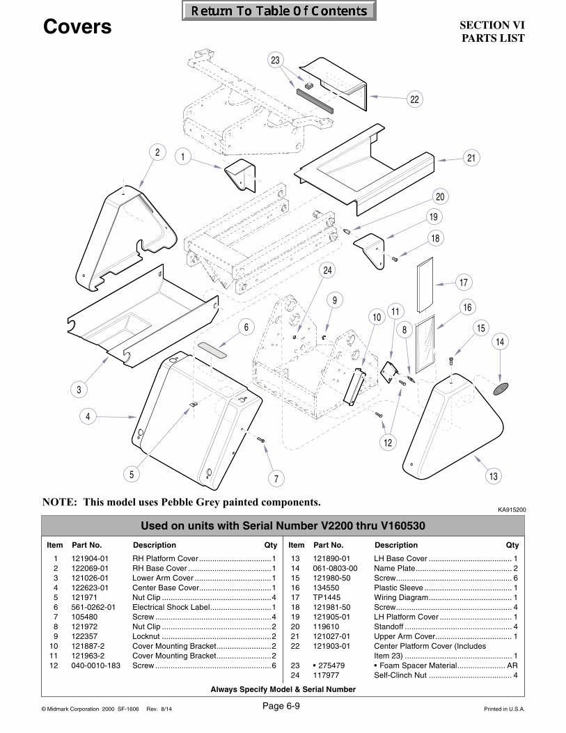
SECTION VIPARTS LIST
© Midmark Corporation 2000 SF-1606 Printed in U.S.A.
Always Specify Model & Serial Number
Page 6-9Rev. 8/14
Covers
KA915200
Used on units with Serial Number V2200 thru V160530
Item Part No. Description Qty Item Part No. Description Qty
1 121904-01 RH Platform Cover .................................12 122069-01 RH Base Cover ......................................13 121026-01 Lower Arm Cover ...................................14 122623-01 Center Base Cover.................................15 121971 Nut Clip ..................................................46 561-0262-01 Electrical Shock Label............................17 105480 Screw .....................................................48 121972 Nut Clip ..................................................29 122357 Locknut ..................................................2
10 121887-2 Cover Mounting Bracket.........................211 121963-2 Cover Mounting Bracket.........................212 040-0010-183 Screw .....................................................6
13 121890-01 LH Base Cover ...................................... 114 061-0803-00 Name Plate............................................ 215 121980-50 Screw..................................................... 616 134550 Plastic Sleeve ........................................ 117 TP1445 Wiring Diagram...................................... 118 121981-50 Screw..................................................... 419 121905-01 LH Platform Cover ................................. 120 119610 Standoff ................................................. 421 121027-01 Upper Arm Cover................................... 122 121903-01 Center Platform Cover (Includes
Item 23) ................................................. 123 • 275479 • Foam Spacer Material...................... AR24 117977 Self-Clinch Nut ...................................... 4
NOTE: This model uses Pebble Grey painted components.

SECTION VIPARTS LIST
Always Specify Model & Serial Number
© Midmark Corporation 2000 SF-1606 Printed in U.S.A.
12
3
4
5
6
7
25
13
15
16
17
18
19
20
21
22
23
24
11108
12
9
14
Page 6-9.1Rev. 8/14
DA173400i
Used on units with Serial Number V160531 thru V456962
Item Part No. Description Qty Item Part No. Description Qty
1 121904-01 RH Platform Cover ........................... 12 122069-01 RH Base Cover ................................ 13 121026-01 Lower Arm Cover ............................. 14 122623-01 Center Base Cvr. (Concept L/R Clas.)15 121971 Nut Clip ............................................ 46 561-0262-01 Electrical Shock Label...................... 17 105480 Screw ............................................... 48 121972 Nut Clip ............................................ 29 122357 Locknut ............................................ 2
10 121887-2 Cover Mounting Bracket................... 211 121963-2 Cover Mounting Bracket................... 212 040-0010-183 Screw ............................................... 613 122075-01 LH Base Cover (120 VAC, 2 hole).... 1
053-1584-00-216 LH Base Cover (240 VAC, 3 hole) ... 1
14 061-0808-05 Label, Fuse Replacement (120 VAC......1061-0808-06 Label, Fuse Replacement (240 VAC).....1
15 061-0803-00 Name Plate ............................................216 121980-50 Screw .....................................................617 134550 Plastic Sleeve.........................................118 TP1445 Wiring Diagram ......................................119 121981-50 Screw .....................................................420 121905-01 LH Platform Cover .................................121 119610 Standoff..................................................422 121027-01 Upper Arm Cover ...................................123 121903-01 Center Platform Cover (Includes
Item 24)..................................................124 • 275479 • Foam Spacer Material ......................AR25 117977 Self-Clinch Nut .......................................4
Covers
NOTE: This model uses Pebble Grey painted components.

SECTION VIPARTS LIST
© Midmark Corporation 2000 SF-1606 Printed in U.S.A.
Always Specify Model & Serial Number
3
4
5
6
7 13
15
16
17
18
19
20
21
22
23
24
11108
12
9
14
1
Page 6-9.2Rev. 8/14
Used on units with Serial Number V456963 thru Present
Item Part No. Description Qty Item Part No. Description Qty
1 121904-01 RH Platform Cover ...........................12A 122069-01 Base Cover (non-rotation) 12B 121889-01 Base Cover.......................................1
3 121026-01 Lower Arm Cover ..............................14 122623-01 Center Base Cvr. (Concept L/R Clas.)15 121971 Nut Clip.............................................46 561-0262-01 Electrical Shock Label ......................17 105480 Screw ...............................................48 121972 Nut Clip.............................................29 122357 Locknut .............................................2
10 121887-2 Cover Mounting Bracket ...................211 121963-2 Cover Mounting Bracket ...................212 040-0010-183 Screw ...............................................6
13 053-1807-00-216 Base Cover ....................................... 114 117977 Self-Clinch Nut .................................... 415 061-0803-00 Name Plate............................................ 216 121980-50 Screw .................................................... 617 134550 Plastic Sleeve ........................................ 118 TP1445 Wiring Diagram...................................... 119 121981-50 Screw .................................................... 420 121905-01 LH Platform Cover ................................. 121 119610 Standoff ................................................. 422 121027-01 Upper Arm Cover .................................. 123 121903-01 Center Platform Cover (Includes
Item 24) ................................................. 124 • 275479 • Foam Spacer Material ..................... AR
Covers
NOTE: This model uses Pebble Grey painted components.
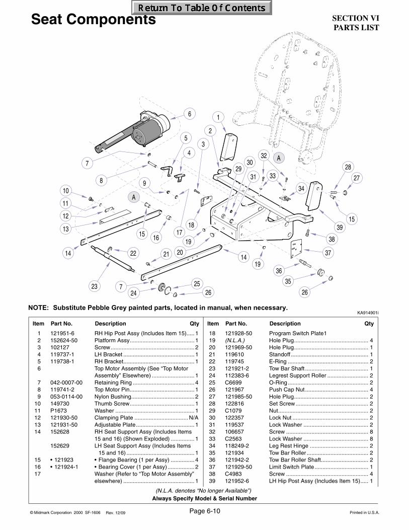
SECTION VIPARTS LIST
Always Specify Model & Serial Number
© Midmark Corporation 2000 SF-1606 Printed in U.S.A.
A
A
1
2
14
1718
19
202122
2324
25 35
36
37
38
39
4
53
6
7
8 910
13
11
12
15 16
726
27
28
1419
26
30
3129
32
33
34
15
Page 6-10Rev. 12/09
KA914901i
Item Part No. Description Qty Item Part No. Description Qty
1 121951-6 RH Hip Post Assy (Includes Item 15)..... 12 152624-50 Platform Assy......................................... 13 102127 Screw..................................................... 24 119737-1 LH Bracket ............................................. 15 119738-1 RH Bracket............................................. 16 Top Motor Assembly (See “Top Motor
Assembly” Elsewhere) ........................... 17 042-0007-00 Retaining Ring ....................................... 48 119741-2 Top Motor Pin......................................... 19 053-0114-00 Nylon Bushing........................................ 2
10 149730 Thumb Screw......................................... 111 P1673 Washer .................................................. 112 121930-50 Clamping Plate ..................................N/A13 121931-50 Adjustable Plate..................................... 114 152628 RH Seat Support Assy (Includes Items
15 and 16) (Shown Exploded) ............... 1152629 LH Seat Support Assy (Includes Items
15 and 16) ........................................... 115 • 121923 • Flange Bearing (1 per Assy) ............... 416 • 121924-1 • Bearing Cover (1 per Assy) ................. 217 Washer (Refer to “Top Motor Assembly”
elsewhere) ............................................. 1
18 121928-50 Program Switch Plate119 (N.L.A.) Hole Plug............................................... 420 121969-50 Hole Plug............................................... 121 119610 Standoff ................................................. 122 119745 E-Ring ................................................... 223 121921-2 Tow Bar Shaft ........................................ 124 112383-6 Legrest Support Roller .......................... 225 C6699 O-Ring................................................... 226 121967 Push Cap Nut ........................................ 427 121985-50 Hole Plug............................................... 228 122816 Set Screw .............................................. 229 C1079 Nut......................................................... 230 122357 Lock Nut ................................................ 231 119537 Lock Washer ......................................... 232 106657 Screw .................................................... 833 C2563 Lock Washer ......................................... 834 118249-2 Leg Rest Hinge ..................................... 235 121934 Tow Bar Roller ....................................... 236 121942-2 Tow Bar Roller Shaft.............................. 237 121929-50 Limit Switch Plate.................................. 138 C4983 Screw .................................................... 439 121952-6 LH Hip Post Assy (Includes Item 15)..... 1
(N.L.A. denotes “No longer Available”)
Seat Components
NOTE: Substitute Pebble Grey painted parts, located in manual, when necessary.

SECTION VIPARTS LIST
© Midmark Corporation 2000 SF-1606 Printed in U.S.A.
Always Specify Model & Serial Number
A
A
1
2
14
1718
19
202122
2324
25 35
36
37
38
39
4
53
6
7
89
10
13
11
12
15 16
726
27
28
1419
26
30
3129
32
33
34
15
40
Page 6-11Rev. 04/10
KA914901i
Item Part No. Description Qty Item Part No. Description Qty
1 121951-01 RH Hip Post Assy (Includes Item 15) .... 12 152624-00 Platform Assy ........................................ 13 102127 Screw .................................................... 24 119737-50 LH Bracket............................................. 15 119738-50 RH Bracket ............................................ 16 Top Motor Assembly (See “Top Motor
Assembly” Elsewhere)........................... 17 042-0007-00 Retaining Ring....................................... 48 119741-2 Top Motor Pin ........................................ 19 053-0114-00 Nylon Bushing ....................................... 2
10 149730 Thumb Screw ........................................ 111 P1673 Washer .................................................. 112 121930-50 Clamping Plate (Obsolete) .................N/A13 121931-50 Adjustable Plate .................................... 114 152628-01 RH Seat Support Assy (Includes Items
15 and 16) (Shown Exploded)............... 1152629-01 LH Seat Support Assy (Includes Items
15 and 16) .......................................... 115 • 121923 • Flange Bearing (1 per Assy)............... 416 • 121924-50 • Bearing Cover (1 per Assy) ................ 217 Washer (Refer to “Top Motor Assembly”
elsewhere)............................................. 118 121928-50 Program Switch Plate ......................... 1
19 053-1333-50 Hole Plug ............................................... 420 120236 Hole Plug ............................................... 121 119610 Standoff .................................................122 119745 E-Ring....................................................223 121921-2 Tow Bar Shaft ........................................ 124 112383-6 Legrest Support Roller........................... 225 C6699 O-Ring ................................................... 226 121967 Push Cap Nut ........................................ 427 053-1334-50 Hole Plug ............................................... 228 122816 Set Screw .............................................. 229 C1079 Nut ......................................................... 230 122357 Lock Nut.................................................231 119537 Lock Washer .......................................... 232 106657 Screw..................................................... 833 C2563 Lock Washer .......................................... 834 118249-2 Leg Rest Hinge ...................................... 235 121934 Tow Bar Roller .......................................236 121942-2 Tow Bar Roller Shaft .............................. 237 121929-50 Limit Switch Plate .................................. 138 040-0375-76 Screw..................................................... 439 121952-01 LH Hip Post Assy (Includes Item 15) ..... 140 045-0001-04 Lockwasher............................................ 1
Seat Components
NOTE: This model uses Pebble Grey painted components.

SECTION VIPARTS LIST
Always Specify Model & Serial Number
© Midmark Corporation 2000 SF-1606 Printed in U.S.A.Rev. 12/09
KA915100
Item Part No. Description Qty Item Part No. Description Qty
1 (N.L.A.) Chair Back [With switch mtg. holes] ......(Biltmore Classic Only) ..........................1
(N.L.A.) Chair Back [Without switch mtg. holes](Concept L/R Classic Only)....................1
2 121943 Fixed Tang Guide ...................................13 120975 Floating Tang Guide...............................14 120976 Tang Guide Compensator ......................25 P1215 Nut .........................................................26 108850 Screw .....................................................27 040-0010-144 Screw .....................................................38 152094 Tang Guide Plate Assembly
(Includes Items 9 thru 11) ......................19 • 121055 • Headrest Adjustment Label .................1
10 • 120955-50 • Tang Guide Plate ................................ 111 • 120981 • Tang Bearing....................................... 1
12 275505 Velcro Loop............................................ 213 121967 Push Nut Cap ........................................ 214 121926-2 Pin ......................................................... 215 120102 Set Screw .............................................. 416 (N.L.A.) Hole Plug ............................................ 217 121944 Flat Washer ........................................... 218 121927-00 Hip Pin ................................................... 219 108965 Bumper .................................................. 120 122021 Elevator Bolt .......................................... 4
(N.L.A. denotes “No longer Available”)
Back Components
Page 6-12
NOTE: Substitute Pebble Grey painted parts, located in manual, when necessary.
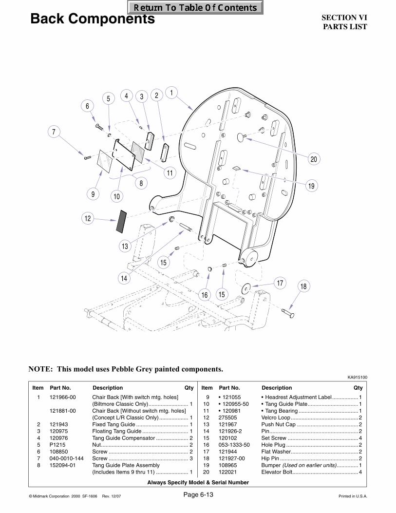
SECTION VIPARTS LIST
© Midmark Corporation 2000 SF-1606 Printed in U.S.A.
Always Specify Model & Serial Number
Page 6-13
KA915100
Item Part No. Description Qty Item Part No. Description Qty
1 121966-00 Chair Back [With switch mtg. holes](Biltmore Classic Only).......................... 1
121881-00 Chair Back [Without switch mtg. holes](Concept L/R Classic Only) ................... 1
2 121943 Fixed Tang Guide .................................. 13 120975 Floating Tang Guide .............................. 14 120976 Tang Guide Compensator ..................... 25 P1215 Nut......................................................... 26 108850 Screw .................................................... 27 040-0010-144 Screw .................................................... 38 152094-01 Tang Guide Plate Assembly
(Includes Items 9 thru 11) ..................... 1
9 • 121055 • Headrest Adjustment Label ................. 110 • 120955-50 • Tang Guide Plate................................. 111 • 120981 • Tang Bearing .......................................112 275505 Velcro Loop............................................ 213 121967 Push Nut Cap ........................................ 214 121926-2 Pin.......................................................... 215 120102 Set Screw .............................................. 416 053-1333-50 Hole Plug ............................................... 217 121944 Flat Washer............................................ 218 121927-00 Hip Pin ................................................... 219 108965 Bumper (Used on earlier units).............. 120 122021 Elevator Bolt........................................... 4
Back Components
NOTE: This model uses Pebble Grey painted components.
Rev. 12/07

SECTION VIPARTS LIST
Always Specify Model & Serial Number
© Midmark Corporation 2000 SF-1606 Printed in U.S.A.
1
10
16
17
18
11
5
2
3
4
5
6
7 89
Old Style
15
1412
13
20 19
KA916002
Item Part No. Description Qty Item Part No. Description Qty
1 109191 Cord Clip................................................ 62 Ground Wire (See Wiring Diagram in
Section V) .............................................. 13 122357 Lock Nut................................................. 14 122994 Micro Switch w/ Roller
(Replaces Old Style) ........................... 15 122806 Screw..................................................... 46 4P429 Nut Bar................................................... 27 045-0001-93 Washer .................................................. 28 146978 Micro Switch .......................................... 19 119633 Actuator ................................................. 1
10 P14718 Lock Washer .......................................... 111 102217 Screw .................................................. 1
12 (N.L.A.) Switch Bezel (Biltmore Classic Only) .... 213 120060 Membrane Switch (Biltmore Clas. Only) 214 122010 Stud [0.875 in.] (Biltmore Classic Only) 215 122009 Stud [0.625 in.] (Biltmore Classic Only) 216 121655 Cable Clamp (Biltmore Classic Only) .... 717 Screw (Biltmore Classic Only)............... 618 122357 Lock Nut (Biltmore Classic Only)........... 419 119758 Washer (Biltmore Classic Only) ............ 120 Top Motor Assy (Refer to “Top Motor
Assembly” elsewhere. Refer to “SeatComponents” for connecting hardware.)1
(N.L.A. denotes “No longer Available”)
Page 6-14Rev. 12/09
Top Electrical Components
NOTE: Substitute Pebble Grey painted parts, located in manual, when necessary.
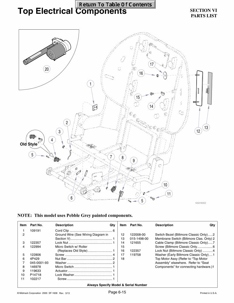
SECTION VIPARTS LIST
© Midmark Corporation 2000 SF-1606 Printed in U.S.A.
Always Specify Model & Serial Number
1
10
16
17
11
5
2
3
4
5
6
7 89
Old Style
15
14
1213
20
NOTE: This model uses Pebble Grey painted components.
Item Part No. Description Qty Item Part No. Description Qty
1 109191 Cord Clip ............................................... 62 Ground Wire (See Wiring Diagram in
Section V).............................................. 13 122357 Lock Nut ................................................ 14 122994 Micro Switch w/ Roller
(Replaces Old Style) ........................... 15 122806 Screw .................................................... 46 4P429 Nut Bar .................................................. 27 045-0001-93 Washer .................................................. 28 146978 Micro Switch .......................................... 19 119633 Actuator ................................................. 1
10 P14718 Lock Washer.......................................... 111 102217 Screw .................................................. 1
12 122008-00 Switch Bezel (Biltmore Classic Only) .....213 015-1498-00 Membrane Switch (Biltmore Clas. Only) 214 121655 Cable Clamp (Biltmore Classic Only).....715 Screw (Biltmore Classic Only.................616 122357 Lock Nut (Biltmore Classic Only) ...........417 119758 Washer (Early Biltmore Classic Only) ....118 Top Motor Assy (Refer to “Top Motor
Assembly” elsewhere. Refer to “SeatComponents” for connecting hardware.)1
Page 6-15Rev. 3/13
Top Electrical Components
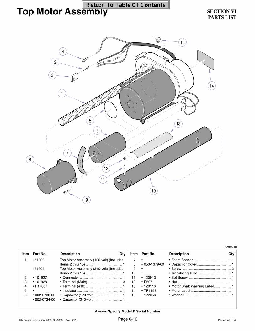
SECTION VIPARTS LIST
Always Specify Model & Serial Number
© Midmark Corporation 2000 SF-1606 Printed in U.S.A.
15
1
2
3
4
5
6
7
9
11
13
14
10
8
12
Page 6-16Rev. 6/16
Top Motor Assembly
KA915001
Item Part No. Description Qty Item Part No. Description Qty
1 151900 Top Motor Assembly (120-volt) (IncludesItems 2 thru 15) ..................................... 1
151905 Top Motor Assembly (240-volt) (IncludesItems 2 thru 15) ..................................... 1
2 • 101927 • Connector ........................................... 13 • 101928 • Terminal (Male) ................................... 34 • P17087 • Terminal (#10) ..................................... 15 • • Insulator .............................................. 16 • 002-0733-00 • Capacitor (120-volt) ........................... 1
• 002-0734-00 • Capacitor (240-volt) ........................... 1
7 • • Foam Spacer .......................................18 • 053-1379-00 • Capacitor Cover...................................19 • • Screw...................................................2
10 • • Translating Tube ..................................111 • 120913 • Set Screw ............................................112 • P507 • Nut .......................................................113 • 120116 • Motor Shaft Warning Label..................114 • TP1158 • Motor Label .........................................115 • 122056 • Washer ................................................1

SECTION VIPARTS LIST
© Midmark Corporation 2000 SF-1606 Printed in U.S.A.
Always Specify Model & Serial Number
1
2
3
4
5
6
8
9
1020
22
2425
2930
31
32
33
34
3536
37
14
1213
11
15
16
19
1817
21
22
23
26
27
2122
28
29
27
262126
23
28
21
22
26
2726
21
38
7
40
Page 6-17Rev 12/09
KA914802
Item Part No. Description Qty Item Part No. Description Qty
1 157122 Screw..................................................... 42 119896-1 Brake Disk ............................................. 13 052-0592-00 Locknut w/hole....................................... 14 119296 Bearing Lock Washer ............................ 15 119295 Bearing Race......................................... 26 119297 Thrust Bearing ....................................... 17 122627 Sleeve .................................................... 28 C4507 Lock Washer .......................................... 29 C1269 Nut ......................................................... 2
10 119882-2 Rotation Lock Stud ................................ 111 119513 Nut ......................................................... 112 151446 Rotation Block Assy (Includes Item 13) . 113 • • Brake Lining ........................................ 114 121148 Set Screw .............................................. 215 152642 Baseplate............................................... 116 117150 Lazy Susan Bearing .............................. 117 119427-2 Rotation Stop ......................................... 218 119319 Screw..................................................... 219 (N.L.A.) Upright Housing Assy ............................ 120 119031-2 Nut ......................................................... 221 119033 Thrust Bearing (Apply 185171
Magnalube) (See Item 39) ................... 1222 119034 Thrust Race (1/32”) (See Item 39).......14
23 119058 Bearing.................................................. 624 041-0625-00 Nut......................................................... 125 111534 Spring Washer....................................... 126 119035 Thrust Race (1/8”) (See Item 39) ........ 1027 155287 Washer (See Item 39) ........................... 428 117086 Bearing.................................................. 229 (N.L.A.) Parallel Arm........................................... 230 151326 Cam Stud Pivot Screw Assy.................. 131 120024-2 Pivot Screw ........................................... 432 151159-50 Lift Arm.................................................. 133 149296-2 Shaft Assy ............................................. 134 117518 Groove Pin ............................................ 135 (N.L.A.) Bracket Assy ......................................... 136 C5253 Screw .................................................... 237 (N.L.A.) Lever Assy (Apply 185171 Magnalube
to Threads)............................................ 138 151336 Groove Pin Pivot Screw Assy................ 139 152621 Thrust Bearing Kit (Not Shown) (Includes
Items 21, 22, 26, 27 in quantities listedAlso Includes Magnalube and Loctite).
40 118286 Chair Base Pad ..................................... 441 041-0750-02 Nut......................................................... 4
(N.L.A. denotes “No longer Available”)
Rotational Base Components (Biltmore Classic)
TORQUE LEGENDITEM# TORQUE
20 10 FT-LBS(13.6 N•M)
30, 31, 38 75 FT-LBS(101.7 N•M)
NOTE: Substitute Pebble Grey painted parts, located in manual, when necessary.

SECTION VIPARTS LIST
Always Specify Model & Serial Number
© Midmark Corporation 2000 SF-1606 Printed in U.S.A.
NOTE: This model uses Pebble Grey painted components.
1
2
3
4
5
6
8
9
1020
22
2425
2930
31
32
33
34
3536
37
14
1213
11
15
16
19
1817
21
22
23
26
27
2122
28
29
27
262126
23
28
21
22
26
2726
21
38
7
40
Page 6-18Rev 1/09
Rotational Base Components (Biltmore Classic)
KA914804i
Used on units with Serial Number V1000 thru V87416
Item Part No. Description Qty Item Part No. Description Qty
1 157122 Screw .....................................................42 119896-1 Brake Disk..............................................13 052-0592-00 Locknut w/hole .......................................14 119296 Bearing Lock Washer.............................15 119295 Bearing Race .........................................26 119297 Thrust Bearing .......................................17 122627 Sleeve ....................................................28 C4507 Lock Washer ..........................................29 C1269 Nut .........................................................2
10 119882-2 Rotation Lock Stud.................................111 119513 Nut .........................................................112 151446 Rotation Block Assy (Includes Item 13) .113 • • Brake Lining.........................................114 121148 Set Screw...............................................215 152642-00 Baseplate ...............................................116 117150 Lazy Susan Bearing...............................117 119427-2 Rotation Stop .........................................218 119319 Screw .....................................................219 151168-00 Upright Housing Assy ............................120 119031-2 Nut .........................................................221 119033 Thrust Bearing (Apply 185171
Magnalube) (See Item 39) ...................1222 119034 Thrust Race (1/32”) (See Item 39) .......14
23 119058 Bearing .................................................. 624 041-0625-00 Nut ......................................................... 125 111534 Spring Washer ....................................... 126 119035 Thrust Race (1/8”) (See Item 39)......... 1027 155287 Washer (See Item 39)............................ 428 117086 Bearing .................................................. 229 121521-00 Parallel Arm ........................................... 230 151326 Cam Stud Pivot Screw Assy .................. 131 120024-2 Pivot Screw............................................ 432 151159-00 Lift Arm .................................................. 133 149296-2 Shaft Assy ............................................. 134 117518 Groove Pin............................................. 135 030-1808-00-216Bracket Assy .......................................... 136 C5253 Screw..................................................... 237 151447-00 Lever Assy (Apply 185171 Magnalube
to Threads) ............................................ 138 151336 Groove Pin Pivot Screw Assy ................ 139 152621 Thrust Bearing Kit (Not Shown) (Includes
Items 21, 22, 26, 27 in quantities listedAlso Includes Magnalube and Loctite).
40 118286 Chair Base Pad...................................... 441 041-0750-02 Nut ......................................................... 4
TORQUE LEGENDITEM# TORQUE
20 10 FT-LBS(13.6 N•M)
30, 31, 38 75 FT-LBS(101.7 N•M)

SECTION VIPARTS LIST
© Midmark Corporation 2000 SF-1606 Printed in U.S.A.
Always Specify Model & Serial Number
1
2
3
4
5
6
8
9
1020
22
2425
2930
31
32
33
34
3637
14
15
18
21
22
23
26
27
2122
28
29
27
2126
23
2822
21
38
7
40
19
1312
11
26
1716
2126
2726
35
KA914805i
Used on units with Serial Number V87417 thru V128688
Item Part No. Description Qty Item Part No. Description Qty
1 157122 Screw .................................................... 42 119896-1 Brake Disk ............................................. 13 052-0592-00 Locknut w/hole....................................... 14 119296 Bearing Lock Washer ............................ 15 119295 Bearing Race......................................... 26 119297 Thrust Bearing....................................... 17 122627 Sleeve.................................................... 28 C4507 Lock Washer.......................................... 29 C1269 Nut......................................................... 2
10 119882-2 Rotation Lock Stud ................................ 111 119513 Nut......................................................... 112 151446 Rotation Block Assy (Includes Item 13). 113 • • Brake Lining ........................................ 114 121148 Set Screw .............................................. 215 152642-00 Baseplate .............................................. 116 117150 Lazy Susan Bearing .............................. 117 119427-2 Rotation Stop......................................... 218 119319 Screw .................................................... 219 030-1563-50 Upright Housing Assy............................ 120 119031-2 Nut......................................................... 221 119033 Thrust Bearing (Apply 185171
Magnalube) (See Item 39)................... 1222 119034 Thrust Race (1/32”) (See Item 39) ...... 14
23 119058 Bearing ..................................................624 041-0625-00 Nut .........................................................125 111534 Spring Washer .......................................126 119035 Thrust Race (1/8”) (See Item 39) .........1027 155287 Washer (See Item 39) ............................428 117086 Bearing ..................................................229 121521-00 Parallel Arm ...........................................230 151326 Cam Stud Pivot Screw Assy ..................131 120024-2 Pivot Screw ............................................432 151159-00 Lift Arm ..................................................133 149296-2 Shaft Assy..............................................134 117518 Groove Pin .............................................135 030-1808-00-216Bracket Assy ........................................ 136 C5253 Screw .....................................................237 151447-00 Lever Assy (Apply 185171 Magnalube
to Threads).............................................138 151336 Groove Pin Pivot Screw Assy ................139 152621 Thrust Bearing Kit (Not Shown) (Includes
Items 21, 22, 26, 27 in quantities listedAlso Includes Magnalube and Loctite).
40 118286 Chair Base Pad......................................441 041-0750-02 Nut .........................................................4
Page 6-18.1Rev 1/09
Rotational Base Components (Biltmore Classic)
NOTE: This model uses Pebble Grey painted components.
TORQUE LEGENDITEM# TORQUE
20 10 FT-LBS(13.6 N•M)
30, 31, 38 75 FT-LBS(101.7 N•M)

SECTION VIPARTS LIST
Always Specify Model & Serial Number
© Midmark Corporation 2000 SF-1606 Printed in U.S.A.
1
2
3
4
5
6
8
9
1020
22
2425
2930
31
32
33
34
3637
14
15
18
21
22
23
26
27
2122
28
29
27
2126
23
2822
21
38
7
40
19
1312
11
26
1716
2126
2726
35
NOTE: This model uses Pebble Grey painted components. KA914803i
Used on units with Serial Number V128689 thru Present
Item Part No. Description Qty Item Part No. Description Qty
1 157122 Screw .................................................... 42 119896-1 Brake Disk ............................................. 13 052-0592-00 Locknut w/hole....................................... 14 119296 Bearing Lock Washer ............................ 15 119295 Bearing Race......................................... 26 119297 Thrust Bearing....................................... 17 122627 Sleeve.................................................... 28 C4507 Lock Washer.......................................... 29 C1269 Nut......................................................... 2
10 119882-2 Rotation Lock Stud ................................ 111 119513 Nut......................................................... 112 151446 Rotation Block Assy (Includes Item 13). 113 • • Brake Lining ........................................ 114 121148 Set Screw .............................................. 215 152642-00 Baseplate .............................................. 116 117150 Lazy Susan Bearing .............................. 117 119427-2 Rotation Stop......................................... 218 119319 Screw .................................................... 219 122643-01 Upright Housing Assy............................ 120 119031-2 Nut......................................................... 221 119033 Thrust Bearing (Apply 185171
Magnalube) (See Item 39)................... 1222 119034 Thrust Race (1/32”) (See Item 39) ...... 14
23 119058 Bearing..................................................624 041-0625-00 Nut.........................................................125 111534 Spring Washer ......................................126 119035 Thrust Race (1/8”) (See Item 39) ........1027 155287 Washer (See Item 39) ...........................428 117086 Bearing..................................................229 051-1081-00-216 Parallel Arm...........................................230 151326 Cam Stud Pivot Screw Assy..................131 120024-2 Pivot Screw ...........................................432 151159-00 Lift Arm..................................................133 149296-2 Shaft Assy .............................................134 117518 Groove Pin ............................................135 030-1808-00-216 Bracket Assy .........................................136 C5253 Screw ....................................................237 151447-00 Lever Assy (Apply 185171 Magnalube
to Threads)............................................138 151336 Groove Pin Pivot Screw Assy................139 152621 Thrust Bearing Kit (Not Shown) (Includes
Items 21, 22, 26, 27 in quantities listedAlso Includes Magnalube and Loctite).
40 118286 Chair Base Pad .....................................441 041-0750-02 Nut.........................................................4
Page 6-18.2Rev 3/13
Rotational Base Components (Biltmore Classic)
TORQUE LEGENDITEM# TORQUE
20 10 FT-LBS(13.6 N•M)
30, 31, 38 75 FT-LBS(101.7 N•M)

SECTION VIPARTS LIST
© Midmark Corporation 2000 SF-1606 Printed in U.S.A.
Always Specify Model & Serial Number
3
56
1011
12
13
14
15
17
2
20
4
82
3
9
8
727
4
93
8
2
16
1
2
7
10
19
Page 6-19Rev 12/09
Non-Rotational Base Components (Concept L/R Classic)
KA924501i
Item Part No. Description Qty Item Part No. Description Qty
1 119031-2 Nut ......................................................... 22 119033 Thrust Bearing (Apply 185171
Magnalube) (See Item 18) ................... 123 119034 Thrust Race (1/32”) (See Item 18).......144 119058 Bearing .................................................. 65 041-0625-00 Nut ......................................................... 16 111534 Spring Washer ....................................... 17 119035 Thrust Race (1/8”) (See Item 18)......... 108 155287 Washer (See Item 18)............................ 49 117086 Bearing .................................................. 2
10 (N.L.A.) Parallel Arm ........................................... 211 120025-2 Pivot Screw............................................ 1
12 120024-2 Pivot Screw ........................................... 413 151159-50 Lift Arm.................................................. 114 149296-2 Shaft Assy ............................................. 115 117518 Groove Pin ............................................ 116 151336 Groove Pin Pivot Screw Assy................ 117 (N.L.A.) Base Plate Weldment............................ 118 152621 Thrust Bearing Kit (Not Shown) (Includes
Items 2, 3, 7 and 8 in quantities listed.Also Includes Magnalube and Loctite).
19 118286 Chair Base Pad ..................................... 420 041-0750-02 Nut......................................................... 4
(N.L.A. denotes “No longer Available”)
TORQUE LEGENDITEM# TORQUE
1 10 FT-LBS(13.6 N•M)
11, 12, 16 75 FT-LBS(101.7 N•M)
NOTE: Substitute Pebble Grey painted parts, located in manual, when necessary.

SECTION VIPARTS LIST
Always Specify Model & Serial Number
© Midmark Corporation 2000 SF-1606 Printed in U.S.A.
3
56
1011
12
13
14
15
17
2
20
4
82
3
9
8
727
4
93
8
2
16
1
2
7
10
19
Page 6-20Rev 1/05
Non-Rotational Base Components (Concept L/R Classic)
KA924501i
Used on units with Serial Number V1000 thru V87416
Item Part No. Description Qty Item Part No. Description Qty
1 119031-2 Nut .........................................................22 119033 Thrust Bearing (Apply 185171
Magnalube) (See Item 18) ...................123 119034 Thrust Race (1/32”) (See Item 18) .......144 119058 Bearing...................................................65 041-0625-00 Nut .........................................................16 111534 Spring Washer .......................................17 119035 Thrust Race (1/8”) (See Item 18) .........108 155287 Washer (See Item 18) ............................49 117086 Bearing...................................................2
10 121521-00 Parallel Arm............................................211 120025-2 Pivot Screw ............................................1
12 120024-2 Pivot Screw............................................ 413 151159-00 Lift Arm .................................................. 114 149296-2 Shaft Assy ............................................. 115 117518 Groove Pin............................................. 116 151336 Groove Pin Pivot Screw Assy ................ 117 153167-00 Base Plate Weldment ............................ 118 152621 Thrust Bearing Kit (Not Shown) (Includes
Items 2, 3, 7 and 8 in quantities listed.Also Includes Magnalube and Loctite).
19 118286 Chair Base Pad...................................... 420 041-0750-02 Nut ......................................................... 4
TORQUE LEGENDITEM# TORQUE
1 10 FT-LBS(13.6 N•M)
11, 12, 16 75 FT-LBS(101.7 N•M)
NOTE: This model uses Pebble Grey painted components.
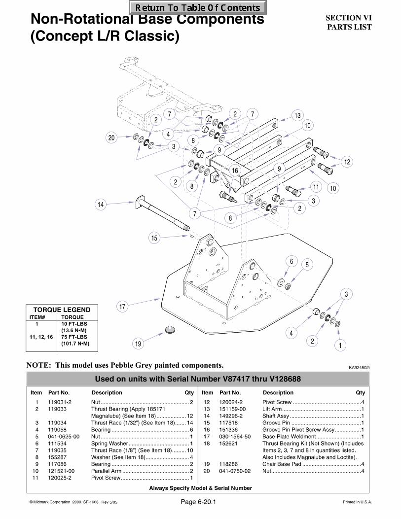
SECTION VIPARTS LIST
© Midmark Corporation 2000 SF-1606 Printed in U.S.A.
Always Specify Model & Serial Number
3
1011
12
13
14
15
17
2
20
4
23
9
8
727
4
9
8
2
16
1
2
10
19
56
3
87
Rev 5/05
Non-Rotational Base Components (Concept L/R Classic)
NOTE: This model uses Pebble Grey painted components.
TORQUE LEGENDITEM# TORQUE
1 10 FT-LBS(13.6 N•M)
11, 12, 16 75 FT-LBS(101.7 N•M)
KA924502i
Used on units with Serial Number V87417 thru V128688
Item Part No. Description Qty Item Part No. Description Qty
1 119031-2 Nut ......................................................... 22 119033 Thrust Bearing (Apply 185171
Magnalube) (See Item 18) ................... 123 119034 Thrust Race (1/32”) (See Item 18)....... 144 119058 Bearing .................................................. 65 041-0625-00 Nut ......................................................... 16 111534 Spring Washer ....................................... 17 119035 Thrust Race (1/8”) (See Item 18)......... 108 155287 Washer (See Item 18)............................ 49 117086 Bearing .................................................. 2
10 121521-00 Parallel Arm ........................................... 211 120025-2 Pivot Screw............................................ 1
12 120024-2 Pivot Screw ............................................413 151159-00 Lift Arm...................................................114 149296-2 Shaft Assy ..............................................115 117518 Groove Pin .............................................116 151336 Groove Pin Pivot Screw Assy.................117 030-1564-50 Base Plate Weldment.............................118 152621 Thrust Bearing Kit (Not Shown) (Includes
Items 2, 3, 7 and 8 in quantities listed.Also Includes Magnalube and Loctite).
19 118286 Chair Base Pad ......................................420 041-0750-02 Nut..........................................................4
Page 6-20.1

SECTION VIPARTS LIST
Always Specify Model & Serial Number
© Midmark Corporation 2000 SF-1606 Printed in U.S.A.
3
1011
12
13
14
15
17
2
20
4
23
9
8
727
4
9
8
2
16
1
2
10
19
56
3
87
Non-Rotational Base Components (Concept L/R Classic)
NOTE: This model uses Pebble Grey painted components.
TORQUE LEGENDITEM# TORQUE
1 10 FT-LBS(13.6 N•M)
11, 12, 16 75 FT-LBS(101.7 N•M)
KA924502i
Used on units with Serial Number V128689 thru Present
Item Part No. Description Qty Item Part No. Description Qty
1 119031-2 Nut ....................................................... 22 119033 Thrust Bearing (Apply 185171
Magnalube) (See Item 18) ................. 123 119034 Thrust Race (1/32”) (See Item 18)..... 144 119058 Bearing ................................................ 65 041-0625-00 Nut ....................................................... 16 111534 Spring Washer ..................................... 17 119035 Thrust Race (1/8”) (See Item 18)....... 108 155287 Washer (See Item 18).......................... 49 117086 Bearing ................................................ 2
10 051-1081-00-216 Parallel Arm ......................................... 211 120025-2 Pivot Screw.......................................... 1
12 120024-2 Pivot Screw ............................................413 151159-00 Lift Arm...................................................114 149296-2 Shaft Assy ..............................................115 117518 Groove Pin .............................................116 151336 Groove Pin Pivot Screw Assy.................117 030-1564-50 Base Plate Weldment.............................118 152621 Thrust Bearing Kit (Not Shown) (Includes
Items 2, 3, 7 and 8 in quantities listed.Also Includes Magnalube and Loctite).
19 118286 Chair Base Pad ......................................420 041-0750-02 Nut..........................................................4
Page 6-20.2

SECTION VIPARTS LIST
© Midmark Corporation 2000 SF-1606 Printed in U.S.A.
Always Specify Model & Serial Number
2345
78 911
12
13
14
16
23
24
25
2627
28
29
30
31
10
3235
10
1
15
17 18
20
20
21
2119
22
10
28 333436
37
11
11
28
39
38
40
19 16 21
28
41
6
Page 6-21
Base Electrical Components
Used on units with Serial Number CP1000 thru present, PB1000 thru present and V1000 thru V87416
Item Part No. Description Qty Item Part No. Description Qty
1 121321-2 Program Plate ........................................12 050-5664-00 Program Switch Cam .............................13 117706 Spring Washer .......................................14 119593 Lock Nut .................................................15 119690 Snap-in Support (short) .........................26 002-1029-00 Control PC Board (120-volt)...................1
002-1029-01 Control PC Board (240-volt)1* 002-1029-xx Cntl PCB for CN Serial No. Units ...N.L.A.
7 002-0733-00 Capacitor (120-volt Units) ......................1002-0734-00 Capacitor (240-volt Units) ......................1
8 016-0971-00 Capacitor Bracket...................................19 121068 Snap-in Support (long)...........................2
10 122806 Screw .....................................................811 146978 Micro Switch...........................................512 121054-2 Mounting Plate .......................................113 109191 Cord Clip ................................................514 119986 Fuse Warning Label ...............................115 C5287 Screw .....................................................216 P507 Nut .........................................................317 040-0010-183 Screw .....................................................118 117977 Self-Clinch Nut .......................................419 P12575 Lock Washer ..........................................720 117601 Screw .....................................................7
21 121656 Cable Clamp.......................................... 322 121654 Cable Clamp.......................................... 123 015-1526-00 Power Cord 120 VAC (Includes Item 24)1
151454-01 Power Cord 240 VAC (w/o plug) ............ 124 • 061-0743-00 • Warning Tag ........................................ 125 P1673 Washer .................................................. 626 121719 Spacer ................................................... 627 151179 Electrical Connection Plate.................... 128 122357 Lock Nut .............................................. 1329 112504 Ground Label......................................... 230 122358 Lock Nut ................................................ 531 119483 Terminal Block ....................................... 132 155668 Screw..................................................... 233 P14718 Lock Washer.......................................... 234 105155 Lock Washer.......................................... 235 121655 Cable Clamp.......................................... 236 109104 Screw..................................................... 237 119378 Cam ....................................................... 238 121520-2 Limit Switch Bracket .............................. 239 121877 Cable Clamp.......................................... 240 119589 Latching Duct......................................... 141 041-0004-00 Nut ......................................................... 4
Rev. 6/16
* Control PC Boards for units with CN Serial Numbers are Obsolete

SECTION VIPARTS LIST
Always Specify Model & Serial Number
© Midmark Corporation 2000 SF-1606 Printed in U.S.A.
56
8 911
1213
14
16
23
24
26
27
2829
31
33
10
15
17 1821
21
21
22
30
33
32
34
38
20
19 16 21
28
25
37
28
1136
207
39
35
30
234
401
Page 6-21.1Rev. 6/16
Base Electrical Components
Used on units with Serial Number V87417 thru V128688
Item Part No. Description Qty Item Part No. Description Qty
1 050-5865-01-216Program Plate........................................ 12 050-5664-00 Program Switch Cam............................. 13 117706 Spring Washer....................................... 14 119593 Lock Nut ................................................ 15 119690 Snap-in Support (short)......................... 26 002-1029-00 Control PC Board (120-volt) .................. 1
002-1029-01 Control PC Board (240-volt) .................. 17 002-0733-00 Capacitor (120-volt) ............................... 1
002-0734-00 Capacitor (240-volt) ............................... 18 016-0971-00 Capacitor Bracket .................................. 19 121068 Snap-in Support (long) .......................... 2
10 122806 Screw..................................................... 211 146978 Micro Switch .......................................... 512 121054-2 Mounting Plate ...................................... 113 109191 Cord Clip ............................................... 514 119986 Fuse Warning Label .............................. 115 C5287 Screw..................................................... 216 P507 Nut ......................................................... 317 040-0010-183 Screw..................................................... 718 117977 Self-Clinch Nut ...................................... 419 P12575 Lock Washer.......................................... 720 117601 Screw..................................................... 7
21 121656 Cable Clamp ..........................................322 121654 Cable Clamp ..........................................123 015-1526-00 Power Cord 120 VAC (Includes Item 24)1
151454-01 Power Cord 240 VAC (w/o plug) ............124 • 061-0743-00 • Warning Tag ........................................125 050-5856-00 Electrical Connection Plate ....................126 122357 Lock Nut ...............................................1327 112504 Ground Label .........................................228 122358 Lock Nut .................................................529 119483 Terminal Block........................................130 155668 Screw .....................................................231 040-0004-25 Screw .....................................................632 P14718 Lock Washer ..........................................233 105155 Lock Washer ..........................................234 121655 Cable Clamp ..........................................235 109104 Screw .....................................................236 119378 Cam .......................................................237 121520-2 Limit Switch Bracket...............................238 121877 Cable Clamp ..........................................239 119589 Latching Duct .........................................140 041-0004-00 Nut .........................................................4
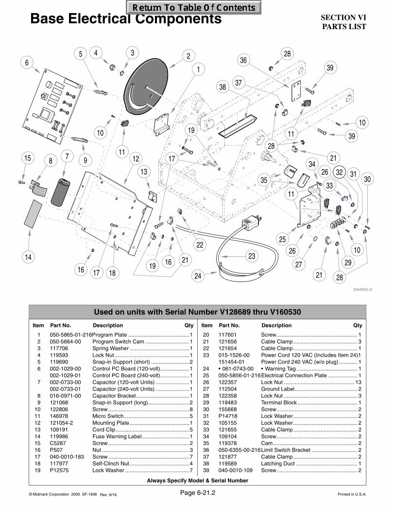
SECTION VIPARTS LIST
© Midmark Corporation 2000 SF-1606 Printed in U.S.A.
Always Specify Model & Serial Number
23456
78 911
12
13
14
16
23
24
26
27
28
29
10
3033
10
1
15
17 18
39
21
21
19
22
10
26 313234
37
36
38
19 16 21
28
39
17
25
11
35
28
11
Page 6-21.2Rev. 6/16
Base Electrical Components
Used on units with Serial Number V128689 thru V160530
Item Part No. Description Qty Item Part No. Description Qty
1 050-5865-01-216Program Plate ........................................12 050-5664-00 Program Switch Cam .............................13 117706 Spring Washer .......................................14 119593 Lock Nut.................................................15 119690 Snap-in Support (short) .........................26 002-1029-00 Control PC Board (120-volt)...................1
002-1029-01 Control PC Board (240-volt)...................17 002-0733-00 Capacitor (120-volt Units) ......................1
002-0733-01 Capacitor (240-volt Units) ......................18 016-0971-00 Capacitor Bracket...................................19 121068 Snap-in Support (long)...........................2
10 122806 Screw .....................................................811 146978 Micro Switch...........................................512 121054-2 Mounting Plate .......................................113 109191 Cord Clip ................................................514 119986 Fuse Warning Label...............................115 C5287 Screw .....................................................216 P507 Nut .........................................................317 040-0010-183 Screw .....................................................718 117977 Self-Clinch Nut .......................................419 P12575 Lock Washer ..........................................7
20 117601 Screw..................................................... 121 121656 Cable Clamp.......................................... 322 121654 Cable Clamp.......................................... 123 015-1526-00 Power Cord 120 VAC (Includes Item 24)1
151454-01 Power Cord 240 VAC (w/o plug) ............ 124 • 061-0743-00 • Warning Tag........................................ 125 050-5856-01-216Electrical Connection Plate ................... 126 122357 Lock Nut .............................................. 1327 112504 Ground Label......................................... 228 122358 Lock Nut ................................................ 329 119483 Terminal Block ....................................... 130 155668 Screw..................................................... 231 P14718 Lock Washer.......................................... 232 105155 Lock Washer.......................................... 233 121655 Cable Clamp.......................................... 234 109104 Screw..................................................... 235 119378 Cam....................................................... 236 050-6355-00-216Limit Switch Bracket .............................. 237 121877 Cable Clamp.......................................... 238 119589 Latching Duct ........................................ 139 040-0010-109 Screw..................................................... 2

SECTION VIPARTS LIST
Always Specify Model & Serial Number
© Midmark Corporation 2000 SF-1606 Printed in U.S.A.
35
267
10 1113
14
15
16
18
25
26
28
29
3031
12
32
12
1
17
19 20
22
23
2321
24
12
28
33
34
39
38
40
21 18 23
30 41
27
13
37
30
13
36
19
18
42
43
44
45
45
3
89
Page 6-21.3Rev. 6/16
Base Electrical Components
Used on units with Serial Number V160531 thru V456962
Item Part No. Description Qty Item Part No. Description Qty
1 050-5865-01-216Program Plate ........................................ 12 050-5664-00 Program Switch Cam............................. 13 053-1159-00 Washer, Thrust (Delrin).......................... 14 525-0063-00 Washer, Belleville................................... 25 119593 Lock Nut................................................. 16 119690 Snap-in Support (short) ......................... 27 002-1029-00 Control PC Board Kit (120-volt) ............. 1
002-1029-01 Control PC Board Kit (240-volt) ............. 18 002-0733-00 Capacitor (120-volt Units) ...................... 1
002-0734-00 Capacitor (240-volt Units) ...................... 19 015-0413-01 Cap, Capacitor (only w/ 120 VAC units). 1
10 015-0412-00 Bracket, Capacitor (120 VAC units) ....... 1016-0971-00 Bracket, Capacitor (240 VAC units) ....... 1
11 121068 Snap-in Support (long) .......................... 212 122806 Screw..................................................... 813 146978 Micro Switch .......................................... 514 121054-2 Mounting Plate....................................... 115 109191 Cord Clip................................................ 516 119986 Fuse Warning Label............................... 117 C5287 Screw..................................................... 218 P507 Nut ......................................................... 319 040-0010-183 Screw..................................................... 720 117977 Self-Clinch Nut....................................... 421 C2563 Lock Washer .......................................... 722 117601 Screw..................................................... 1
23 121656 Cable Clamp.......................................... 324 121654 Cable Clamp.......................................... 125 015-1526-00 Power Cord 120 VAC (Includes Item 24)1
151454-01 Power Cord 240 VAC (w/o plug)............ 126 • 061-0743-00 • Warning Tag........................................ 127 050-5856-01-216Electrical Connection Plate ................... 128 122357 Lock Nut .............................................. 1329 112504 Ground Label ........................................ 230 122358 Lock Nut ................................................ 331 119483 Terminal Block....................................... 132 155668 Screw .................................................... 233 P14718 Lock Washer ......................................... 234 105155 Lock Washer ......................................... 235 121655 Cable Clamp.......................................... 236 109104 Screw .................................................... 237 119378 Cam....................................................... 238 050-6355-00-216Limit Switch Bracket .............................. 239 121877 Cable Clamp.......................................... 240 119589 Latching Duct ........................................ 141 040-0010-109 Screw .................................................... 242 122074-50 Bracket .................................................. 143 015-1304-00 Light, Power ON (120 VAC)................... 144 122541 Fuseholder ............................................ 145 121169 Fuse (10 Amp, 250 VAC, Type F) .......... 1
119485 Fuse (5 Amp, 250 VAC, Type F) ............ 1

SECTION VIPARTS LIST
© Midmark Corporation 2000 SF-1606 Printed in U.S.A.
Always Specify Model & Serial Number
35
267
10 1113
14
15
16
18
25
26
28
29
3031
12
32
12
1
17
19 20
22
23
2321
24
12
30
33
34
39
38
40
21 18 23
28 41
27
13
37
28
13
36
22
22
42
43
45
3
89
45
44
45
Page 6-21.4Rev. 6/16
Base Electrical Components
Used on units with Serial Number V456963 thru Present
Item Part No. Description Qty Item Part No. Description Qty
1 050-5865-01-216 Program Plate ..................................... 12 050-5664-00 Program Switch Cam........................... 13 053-1159-00 Washer, Thrust (Delrin) ....................... 14 525-0063-00 Washer, Belleville ................................ 25 119593 Lock Nut .............................................. 16 119690 Snap-in Support (short)....................... 27 002-1029-00 Control PC Board (120-volt) ................ 1
002-1029-01 Control PC Board (240-volt) ................ 18 002-0733-00 Capacitor (120-volt Units).................... 1
002-0734-00 Capacitor (240-volt Units).................... 19 015-0413-01 Cap, Capacitor (20 VAC units only) ..... 1
10 015-0412-00 Bracket, Capacitor (120 VAC units) ..... 1016-0971-00 Bracket, Capacitor (240 VAC units) ..... 1
11 121068 Snap-in Support (long) ........................ 212 122806 Screw .................................................. 813 146978 Micro Switch ........................................ 514 121054-2 Mounting Plate .................................... 115 109191 Cord Clip ............................................. 516 061-0979-00 Fuse Reference Label (120 VAC)........ 1
061-0979-01 Fuse Reference Label (240 VAC)........ 117 C5287 Screw .................................................. 218 P507 Nut....................................................... 319 040-0010-183 Screw .................................................. 820 117977 Self-Clinch Nut .................................... 421 C2563 Lock Washer........................................ 722 117601 Screw .................................................. 7
23 121656 Cable Clamp .......................................324 121654 Cable Clamp .......................................125 015-1526-00 Power Cord 120 VAC (Incl. Item 26) ...1
151454-01 Power Cord 240 VAC (w/o plug)..........126 • 061-0743-00 • Warning Tag......................................127 050-5856-01-216 Electrical Connection Plate .................128 122357 Lock Nut ............................................1429 061-0653-00 Ground Label ......................................230 122358 Lock Nut ..............................................331 119483 Terminal Block.....................................132 155668 Screw ..................................................233 P14718 Lock Washer .......................................234 105155 Lock Washer .......................................235 121655 Cable Clamp .......................................236 109104 Screw ..................................................237 119378 Cam.....................................................238 050-6355-00-216 Limit Switch Bracket ............................239 121877 Cable Clamp .......................................240 119589 Latching Duct ......................................141 040-0010-109 Screw ..................................................242 122074-50 Bracket ................................................143 015-1304-00 Light, Power ON (120 VAC).................1
015-1304-01 Light, Power ON (240 VAC).................144 Fuses, (Refer to Section 5,
Schematics and Diagrams) .................645 150150 Ground Wire (8") .................................1
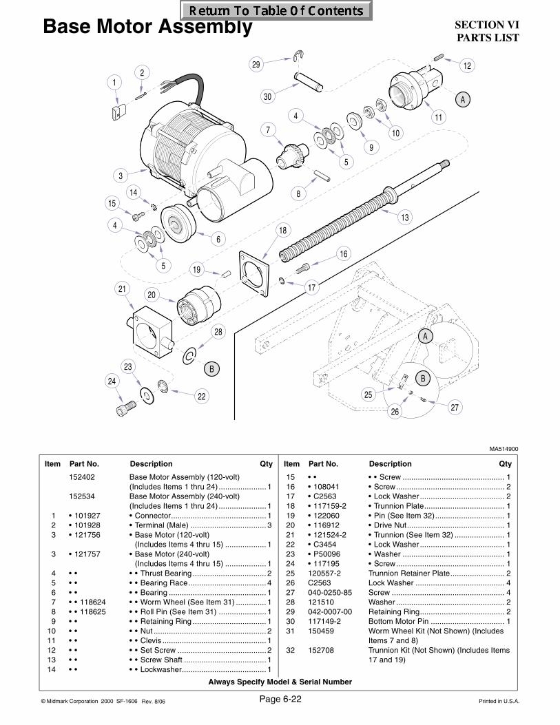
SECTION VIPARTS LIST
Always Specify Model & Serial Number
© Midmark Corporation 2000 SF-1606 Printed in U.S.A.
MA514900
Item Part No. Description Qty Item Part No. Description Qty
152402 Base Motor Assembly (120-volt)(Includes Items 1 thru 24) ...................... 1
152534 Base Motor Assembly (240-volt)(Includes Items 1 thru 24) ...................... 1
1 • 101927 • Connector............................................ 12 • 101928 • Terminal (Male) ................................... 33 • 121756 • Base Motor (120-volt)
(Includes Items 4 thru 15) ................... 13 • 121757 • Base Motor (240-volt)
(Includes Items 4 thru 15) ................... 14 • • • • Thrust Bearing .................................. 25 • • • • Bearing Race.................................... 46 • • • • Bearing ............................................. 17 • • 118624 • • Worm Wheel (See Item 31) .............. 18 • • 118625 • • Roll Pin (See Item 31) ...................... 19 • • • • Retaining Ring .................................. 1
10 • • • • Nut .................................................... 211 • • • • Clevis ................................................ 112 • • • • Set Screw ......................................... 213 • • • • Screw Shaft ...................................... 114 • • • • Lockwasher....................................... 1
15 • • • • Screw ............................................... 116 • 108041 • Screw.................................................. 217 • C2563 • Lock Washer ....................................... 218 • 117159-2 • Trunnion Plate..................................... 119 • 122060 • Pin (See Item 32)................................ 120 • 116912 • Drive Nut............................................. 121 • 121524-2 • Trunnion (See Item 32) ....................... 122 • C3454 • Lock Washer ....................................... 123 • P50096 • Washer ............................................... 124 • 117195 • Screw.................................................. 125 120557-2 Trunnion Retainer Plate......................... 226 C2563 Lock Washer ......................................... 427 040-0250-85 Screw .................................................... 428 121510 Washer .................................................. 229 042-0007-00 Retaining Ring....................................... 230 117149-2 Bottom Motor Pin .................................. 131 150459 Worm Wheel Kit (Not Shown) (Includes
Items 7 and 8)32 152708 Trunnion Kit (Not Shown) (Includes Items
17 and 19)
Page 6-22Rev. 8/06
Base Motor Assembly

SECTION VIPARTS LIST
© Midmark Corporation 2000 SF-1606 Printed in U.S.A.
Always Specify Model & Serial Number
1
2
3
6
45
6
7
8
9
11
10
1213
14
15
16
17
19
20
23
24
21
1822
Top View
Page 6-23Rev. 12/16
MA492302i
Item Part No. Description Qty Item Part No. Description Qty
NLA * Footswitch Assy. (Refer to 002-1859-00) 1 • 119891 • Foot .....................................................42 • 120832-50 • Base Plate .................................... *NLA3 • 121300 • Insulation .............................................14 • 050-6044-00 • Actuator ..............................................45 • 041-0004-00 • Nut .......................................................86 • 146978 • Micro Switch ........................................47 • 121383-2 • Activator...............................................18 • 121998 • Footswitch Housing ...................... *NLA9 • 121382 • Control Pad..........................................1
10 • 113502 • Stud .....................................................811 • 120836 • Operating Label ............................ *NLA12 • 120837 • Bumper ................................................113 • 120861 • Stud .....................................................3
14 • 120839 • Rocker Switch ..................................... 115 • 120898 • Stud..................................................... 216 • 120848 • Green Label ........................................ 117 • 122071 • Yellow Label ........................................ 118 • 152715 • Cable Assembly (Includes Items 20
and 21 [Used on Early Units Only])..... 119 • • 120653 • • Strain Relief Clamp........................... 120 • • P12349 • • O-Ring (Used on Early Units Only)... 121 • 120858-1 • Counter Weight .............................*NLA22 • 120859 • Standoff (Short)................................... 323 • 120860 • Standoff (Long) ................................... 224 • 040-0006-98 • Screw .................................................. 525 • 015-0013-02 • Cable Tie (Not Shown)........................ 2
(N.L.A. denotes “No longer Available”)
Footswitch
NOTE: Substitute Pebble Grey painted parts, located in manual, when necessary.

SECTION VIPARTS LIST
Always Specify Model & Serial Number
© Midmark Corporation 2000 SF-1606 Printed in U.S.A.Page 6-24Rev. 12/16
MA492302i
Item Part No. Description Qty Item Part No. Description Qty
002-1859-00 Footswtich Assembly (Includes Items 1 thru 25) .................................................. 1
1 • 119891 • Foot ..................................................... 42 • 120832-50 • Base Plate........................................... 13 • 121300 • Insulation............................................. 14 • 050-6044-00 • Actuator .............................................. 45 • 041-0004-00 • Nut....................................................... 86 • 146978 • Micro Switch........................................ 47 • 121383-2 • Activator .............................................. 18 • 121998-01 • Footswitch Housing ............................. 19 • 121382 • Control Pad ......................................... 1
10 • 113502 • Stud..................................................... 811 • 061-0806-00 • Operating Label................................... 112 • 120837 • Bumper................................................ 1
13 • 120861 • Stud .................................................... 314 • 120839 • Rocker Switch ..................................... 115 • 120898 • Stud .................................................... 216 • 120848 • Green Label ........................................ 117 • 122071 • Yellow Label ........................................ 118 • 015-1530-00 • Cable Assembly (Includes Items 20
and 21 [Used on Early Units Only]) .... 119 • • 120653 • • Strain Relief Clamp .......................... 120 • • P12349 • • O-Ring (Used on Early Units Only) .. 121 • 120858-50 • Counter Weight ................................... 122 • 120859 • Standoff (Short) .................................. 323 • 120860 • Standoff (Long) ................................... 224 • 040-0006-98 • Screw.................................................. 525 • 015-0013-02 • Cable Tie (Not Shown) ....................... 2
Footswitch
NOTE: This model uses Pebble Grey painted components.
1
2
3
6
45
6
7
8
9
11
10
1213
14
15
16
17
19
20
23
24
21
1822
Top View

SECTION VIPARTS LIST
© Midmark Corporation 2000 SF-1606 Printed in U.S.A.
Always Specify Model & Serial Number
Page 6-25Rev. 8/14
KA924600
Item Part No. Description Qty Item Part No. Description Qty
1 122559 Cable Clamp .......................................... 22 122357 Lock Nut................................................. 53 275255 Vacuum Tubing ..................................A/R4 122582 Cable Clamp .......................................... 25 040-0010-183 Screw..................................................... 2
6 122583 Cable Clamp.......................................... 37 117601 Screw .................................................... 38 153142 Internal Umbilical................................... 19 102308 Cable Tie (Not Shown) .......................... 4
NOTE: This model uses Sterling Grey painted components.
Umbilicals (Concept L/R Classic)
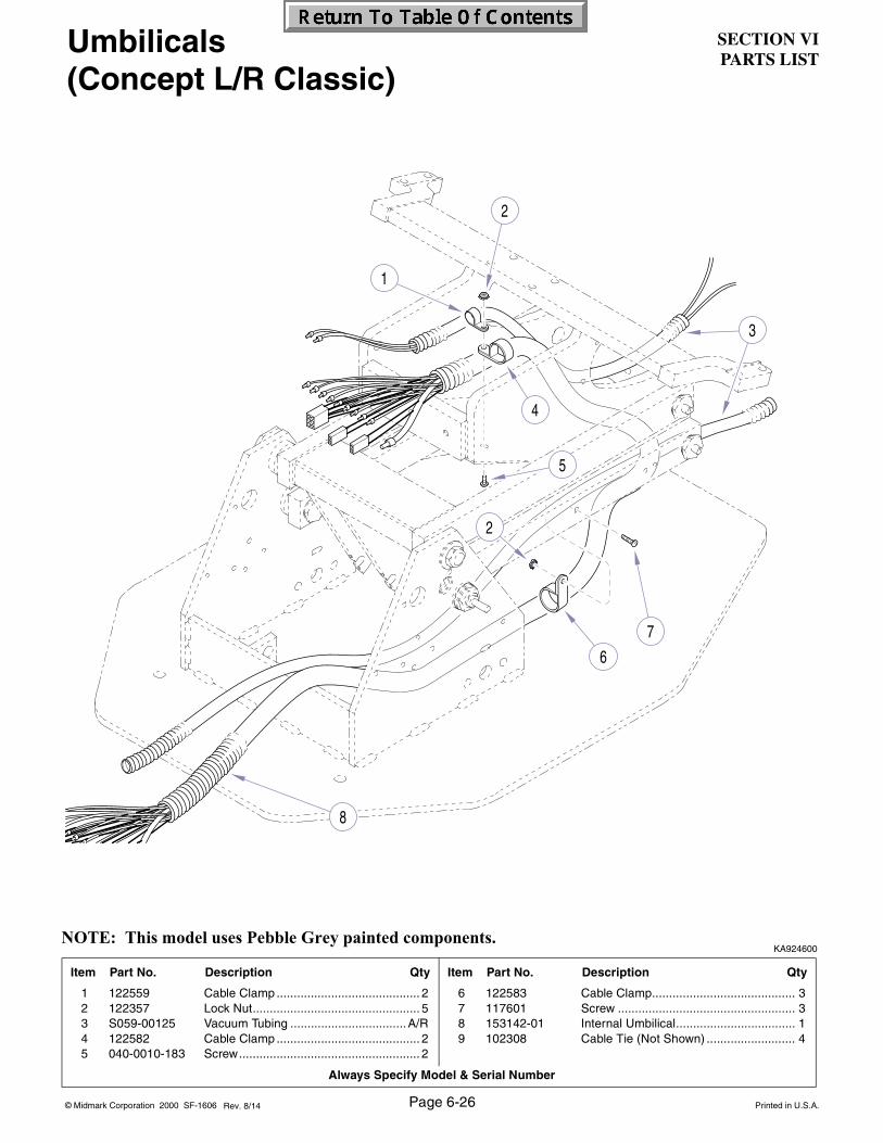
SECTION VIPARTS LIST
Always Specify Model & Serial Number
© Midmark Corporation 2000 SF-1606 Printed in U.S.A.Page 6-26Rev. 8/14
KA924600
Item Part No. Description Qty Item Part No. Description Qty
1 122559 Cable Clamp .......................................... 22 122357 Lock Nut................................................. 53 S059-00125 Vacuum Tubing ..................................A/R4 122582 Cable Clamp .......................................... 25 040-0010-183 Screw..................................................... 2
6 122583 Cable Clamp.......................................... 37 117601 Screw .................................................... 38 153142-01 Internal Umbilical................................... 19 102308 Cable Tie (Not Shown) .......................... 4
Umbilicals (Concept L/R Classic)
NOTE: This model uses Pebble Grey painted components.
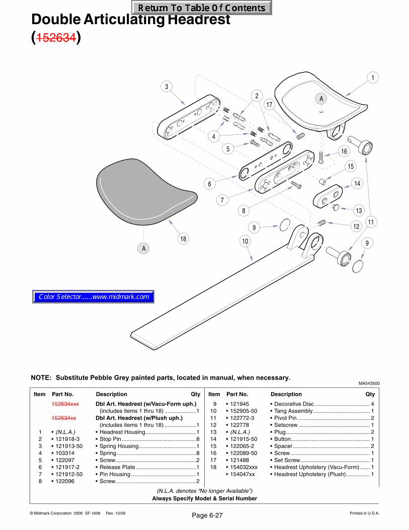
© Midmark Corporation 2000 SF-1606 Printed in U.S.A.Rev. 12/09 Page 6-27
Always Specify Model & Serial Number
Double Articulating Headrest (152634)
MA543500
Item Part No. Description Qty Item Part No. Description Qty
152634xxx Dbl Art. Headrest (w/Vacu-Form uph.)(includes items 1 thru 18) ....................1
152634xx Dbl Art. Headrest (w/Plush uph.)(includes items 1 thru 18) ....................1
1 • (N.L.A.) • Headrest Housing................................12 • 121918-3 • Stop Pin ...............................................83 • 121913-50 • Spring Housing....................................14 • 103314 • Spring ..................................................85 • 122097 • Screw...................................................26 • 121917-2 • Release Plate ......................................17 • 121912-50 • Pin Housing .........................................18 • 122096 • Screw...................................................2
9 • 121945 • Decorative Disc ................................... 410 • 152905-50 • Tang Assembly.................................... 111 • 122772-3 • Pivot Pin .............................................. 212 • 122778 • Setscrew ............................................. 113 • (N.L.A.) • Plug..................................................... 214 • 121915-50 • Button.................................................. 115 • 122065-2 • Spacer................................................. 216 • 122089-50 • Screw .................................................. 117 • 121488 • Set Screw............................................ 118 • 154032xxx • Headrest Upholstery (Vacu-Form) ...... 1
• 154047xx • Headrest Upholstery (Plush)............... 1
(N.L.A. denotes “No longer Available”)
NOTE: Substitute Pebble Grey painted parts, located in manual, when necessary.
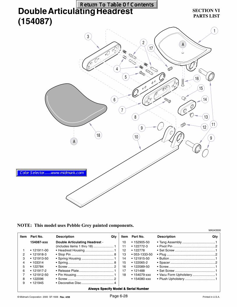
SECTION VIPARTS LIST
Always Specify Model & Serial Number
© Midmark Corporation 2000 SF-1606 Printed in U.S.A.Rev. 4/03 Page 6-28
Always Specify Model & Serial Number
MA543500
Item Part No. Description Qty Item Part No. Description Qty
154087-xxx Double Articulating Headrest -(includes items 1 thru 18) ...................... 1
1 • 121911-00 • Headrest Housing ............................... 12 • 121918-3 • Stop Pin .............................................. 83 • 121913-50 • Spring Housing ................................... 14 • 103314 • Spring.................................................. 85 • 122784 • Screw .................................................. 26 • 121917-2 • Release Plate...................................... 17 • 121912-50 • Pin Housing......................................... 18 • 122096 • Screw .................................................. 29 • 121945 • Decorative Disc ................................... 4
10 • 152905-50 • Tang Assembly ....................................111 • 122772-3 • Pivot Pin ..............................................212 • 122778 • Set Screw ............................................113 • 053-1333-50 • Plug .....................................................214 • 121915-50 • Button ..................................................115 • 122065-2 • Spacer .................................................216 • 122089-50 • Screw...................................................117 • 121488 • Set Screw ............................................118 • 154079-xxx • Vacu Form Upholstery .........................1
• 154080-xxx • Plush Upholstery .................................1
Double Articulating Headrest (154087)
NOTE: This model uses Pebble Grey painted components.
Rev. 4/08
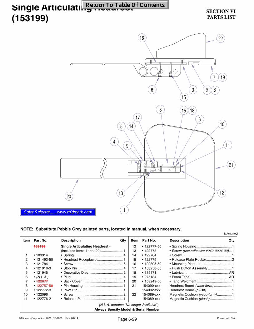
SECTION VIPARTS LIST
© Midmark Corporation 2000 SF-1606 Printed in U.S.A.
Always Specify Model & Serial Number
3 326
1
4
56
9
7
10
15
11
1213
14
15
16
20
1718
19
8
22
21
Page 6-29Rev. 8/6/14
Single Articulating Headrest (153199)
MA613400i
Item Part No. Description Qty Item Part No. Description Qty
153199 Single Articulating Headrest -(includes items 1 thru 20) ...................... 1
1 • 103314 • Spring ................................................. 42 • 121493-50 • Headrest Receptacle .......................... 13 • 121784 • Screw.................................................. 64 • 121918-3 • Stop Pin .............................................. 45 • 121945 • Decorative Disc................................... 26 • (N.L.A.) • Plug..................................................... 47 • 122677 • Back Cover ......................................... 18 • 122757-50 • Pin Housing ........................................ 19 • 122772-3 • Pivot Pin.............................................. 1
10 • 122096 • Screw.................................................. 211 • 122776-2 • Release Plate ..................................... 1
12 • 122777-50 • Spring Housing....................................113 • 122778 • Screw (use adhesive #042-0024-00)...114 • 122784 • Screw ..................................................115 • 122775 • Release Plate Rocker..........................216 • 122805-50 • Mounting Plate ....................................117 • 153258-50 • Push Button Assembly ........................118 • 185171 • Lubricant ..........................................AR19 • 275184 • Foam Tape .......................................AR20 • 153249-50 • Tang Weldment ...................................121 154090-xxx Headrest Board (vacu-form) ..................1
154092-xxx Headrest Board (plush)..........................122 154089-xxx Magnetic Cushion (vacu-form) ...............1
154089-xxx Magnetic Cushion (plush) ........................
(N.L.A. denotes “No longer Available”)
NOTE: Substitute Pebble Grey painted parts, located in manual, when necessary.
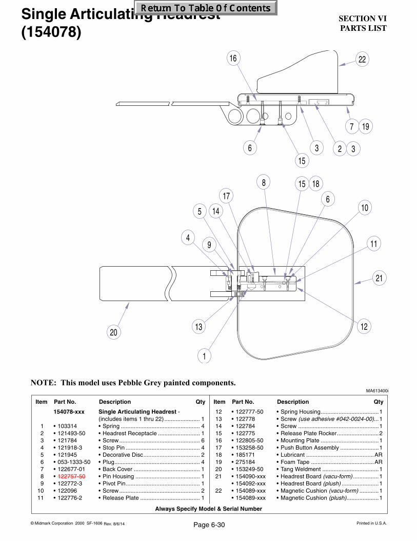
SECTION VIPARTS LIST
Always Specify Model & Serial Number
© Midmark Corporation 2000 SF-1606 Printed in U.S.A.Rev. 8/6/14
3 326
1
4
56
9
7
10
15
11
1213
14
15
16
20
1718
19
8
22
21
Page 6-30
Single Articulating Headrest (154078)
MA613400i
Item Part No. Description Qty Item Part No. Description Qty
154078-xxx Single Articulating Headrest -(includes items 1 thru 22) ...................... 1
1 • 103314 • Spring ................................................. 42 • 121493-50 • Headrest Receptacle .......................... 13 • 121784 • Screw.................................................. 64 • 121918-3 • Stop Pin .............................................. 45 • 121945 • Decorative Disc................................... 26 • 053-1333-50 • Plug..................................................... 47 • 122677-01 • Back Cover ......................................... 18 • 122757-50 • Pin Housing ........................................ 19 • 122772-3 • Pivot Pin.............................................. 1
10 • 122096 • Screw.................................................. 211 • 122776-2 • Release Plate ..................................... 1
12 • 122777-50 • Spring Housing....................................113 • 122778 • Screw (use adhesive #042-0024-00)...114 • 122784 • Screw ..................................................115 • 122775 • Release Plate Rocker..........................216 • 122805-50 • Mounting Plate ....................................117 • 153258-50 • Push Button Assembly ........................118 • 185171 • Lubricant ..........................................AR19 • 275184 • Foam Tape .......................................AR20 • 153249-50 • Tang Weldment ...................................121 • 154090-xxx • Headrest Board (vacu-form) ................1
• 154092-xxx • Headrest Board (plush) .......................122 • 154089-xxx • Magnetic Cushion (vacu-form) ............1
• 154089-xxx • Magnetic Cushion (plush)....................1
NOTE: This model uses Pebble Grey painted components.

SECTION VIPARTS LIST
© Midmark Corporation 2000 SF-1606 Printed in U.S.A.
Always Specify Model & Serial Number
Rev. 12/09
6
10
9
3
7
14
5
2
4
13
15
1
1
16
11
48
12
17
IV Armboard (152565)
MA613300i
Item Part No. Description Qty Item Part No. Description Qty
152565 IV Armboard(includes items 1 thru 17) ......................1
1 • 117366 • Knob (use adhesive #042-0024-00) ....22 • 118249-2 • Legrest Hinge ......................................13 • 120611-2 • Shoulder Screw ...................................14 • 120950 • Screw ..................................................65 • 121839-50 • Toe Block.............................................16 • 121840-2 • Armboard Rod .....................................17 • 121850 • Screw (use adhesive #042-0024-00)...28 • 121847-50 • Bottom Cover.......................................1
9 • 121848-50 • Mounting Block ................................... 110 • 121845-50 • Mounting Bracket ................................ 111 • 121853-50 • Strut .................................................... 112 • 152558-50 • Post Assembly .................................... 113 • 152563 • Slide Assembly ................................... 114 • 152564xxx • Upholstery........................................... 115 • 177723 • Velcro (loop - female) ................... [.011]16 • 275184 • Foam Tape ..................................... [.25]17 • 152562 • Arm Band............................................ 1
(N.L.A. denotes “No longer Available”)
Page 6-31
NOTE: Substitute Pebble Grey painted parts, located in manual, when necessary.

SECTION VIPARTS LIST
Always Specify Model & Serial Number
© Midmark Corporation 2000 SF-1606 Printed in U.S.A.Rev. 4/08
6
10
9
3
7
14
5
2
4
13
15
1
1
16
11
48
12
17
NOTE: This model uses Pebble Grey painted components.MA613300i
Item Part No. Description Qty Item Part No. Description Qty
154088-xxx IV Armboard(includes items 1 thru 17) ...................... 1
1 • 117366 • Knob (use adhesive #042-0024-00).... 22 • 118249-2 • Legrest Hinge...................................... 13 • 120611 • Shoulder Screw................................... 14 • 120950 • Screw .................................................. 65 • 121839-50 • Toe Block ............................................ 16 • 121840-2 • Armboard Rod .................................... 17 • 121850 • Screw (use adhesive #042-0024-00) .. 28 • 121847-50 • Bottom Cover ...................................... 1
9 • 121848-50 • Mounting Block ....................................110 • 121845-50 • Mounting Bracket.................................111 • 121853-50 • Strut .....................................................112 • 152558-50 • Post Assembly .....................................113 • 152563-01 • Slide Assembly ....................................114 • 152564xxx • Upholstery ...........................................115 • 177723 • Velcro (loop - female)....................[.011]16 • 275184 • Foam Tape......................................[.25]17 • 152562 • Arm Band ............................................1
Page 6-32
IV Armboard (154088)

SECTION VIPARTS LIST
© Midmark Corporation 2000 SF-1606 Printed in U.S.A.
Always Specify Model & Serial Number
1
2
3
45
6
78
11
16
9
1012
13
1415
18
19
22
2320
21
17
24
25
Rev. 5/10
NOTE: This model uses Pebble Grey painted components.
Page 6-33
L/R Light Bracket Components(non rotational units only)
DA2555i
Item Part No. Description Qty Item Part No. Description Qty
029-3002-00 L/R Arm Adapter-Non Rotational Only(includes items 1 thru 26) ...................... 1
1 • 122638-01 • Bracket Cover ..................................... 12 • 121981-50 • Screw.................................................. 43 • S006-00895 • Envelope ............................................. 14 • TPW1700 • Flow Diagram...................................... 15 • 275184 • Foam Tape (per foot) .......................... 16 • 122552 • Screw.................................................. 17 • 122554 • Washer................................................ 18 • 109191 • Cord Clip............................................. 19 • 122357 • Nut ...................................................... 1
10 • 122636 • Cable Clamp ....................................... 111 • 105480 • Screw.................................................. 212 • 121127 • Screw.................................................. 1
13 • 122539-50 • Wire Harness Plate .............................114 • 115300 • Screw ..................................................215 • 153054-50 • Mounting Bracket.................................116 • 030-1465-50 • Lower Arm Mounting Bracket ..............117 • 122547 • Set Screw ............................................318 •042-0206-00 • Screw ..................................................119 • 122550 • Light Arm Stop Bumper.......................120 • 122549 • Unit Arm Stop Bumper ........................121 • 107995 • Screw ..................................................122 • 122554 • Washer ................................................123 • 122553 • Nut.......................................................124 • 040-0010-109 • Screw ..................................................125 • 061-0819-00 • Extension Bolt Cover ...........................126 • 121877 • Cable Clamp (not shown)....................1

© Midmark Corporation 2000 SF-1621 Page 7-1 Printed in U.S.A.
The Technical Publications Department of Midmark Corporation takes pride in its publications. We are sure that our manuals will fill all of your needs when you are performing scheduled maintenance, servicing, or repairs on a Midmark product.
Page(s) and Paragraph(s) Needing Changed:
Description of Error or Desired Change:
Please fax or mail a copy of this completed comment sheet to:
Midmark CorporationATTN: Technical Publications Department60 Vista DriveVersailles, Ohio 45380Fax: (937) 526-5542
However, if you find any errors or feel that there should be a change, addition, or deletion to a manual, please let us know!
COMMENTS

ACCT #: P.O. #: DATE:
FAX ORDERING FORM(SERVICE PARTS ONLY)
NAME: SHIP TO:
ADDRESS:
CITY, ST.:
CONTACT:
PHONE:
QTY. PART # DESCRIPTION (SPECIFY COLOR OF ITEM IF APPLICABLE) COLOR CODE PRICE/PER
METHOD OF SHIPMENTNON-EMERGENCY ORDER - TO SHIP WITHIN 72 HOURS IFPART(S) IN STOCK.
EMERGENCY ORDER - TO SHIP WITHIN 24 HOURS IF PART(S)IN STOCK (IF ORDER IS RECEIVED BEFORE 1:00 P.M. E.S.T).
SEND NOTIFICATION IF PARTS ARE NOT AVAILABLE TO SHIPWITHIN 24 HOURS VIAE-MAIL OR FAX TO:
NOTES:• ALL BLOCKED AREAS MUST BE COMPLETED.• USE FOR NON-WARRANTY FAX ORDERS ONLY. WARRANTY ORDERS MUST BE TELEPHONED IN (1-800-MIDMARK).
ATTENTION: SERVICE DEPARTMENT FAX#: 877-249-1793
NEXT DAY A.M.
NEXT DAY P.M.
2ND DAY
GROUND
NEXT DAY A.M.
NEXT DAY P.M.
2ND DAY
ECONOMY
UPS FED EX
OTHER
TOTAL COST: $
© Midmark Corporation 2000 Rev. 1/07 Page 7-2 Printed in U.S.A.


© Midmark Corporation - 2005 Printed in U.S.A.
Subject to change without notice.Refer to www.Documark.com for latest revision.
Midmark Corporation60 Vista DriveP.O. Box 286Versailles, Ohio 45380-0286937-526-3662Fax 937-526-5542midmark.com