demo version of the second round tasks
TRANSCRIPT
DEMO VERSION OF THE SECOND ROUND TASKS
1
Engineering & Technology
Sample test
Task 1 (2 points)
A wheel rotates on an axis according to the law:
𝜑(𝑡) = 2𝑡2(rad).
Find its angular velocity at t = 0.5 (s).
Solution:
𝜔 =𝑑𝜑(𝑡)
𝑑𝑡= 4𝑡=2 rad/s
Answer: 2 rad/s
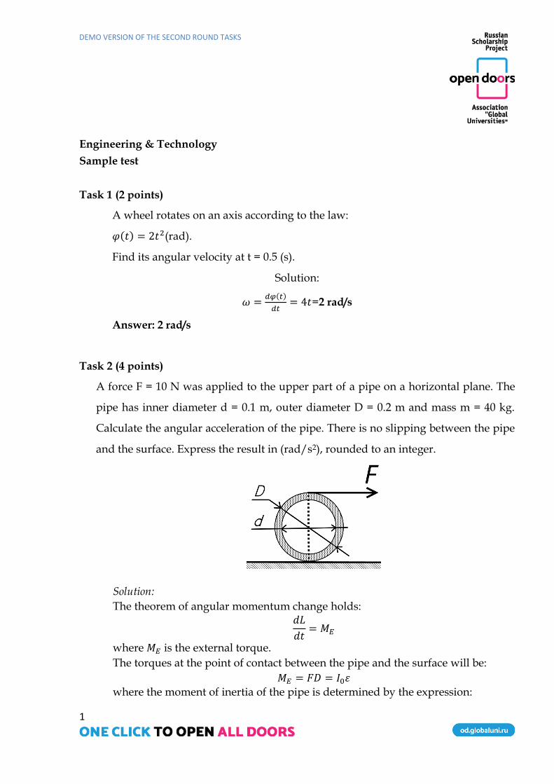
Task 2 (4 points)
A force F = 10 N was applied to the upper part of a pipe on a horizontal plane. The
pipe has inner diameter d = 0.1 m, outer diameter D = 0.2 m and mass m = 40 kg.
Calculate the angular acceleration of the pipe. There is no slipping between the pipe
and the surface. Express the result in (rad/s2), rounded to an integer.
Solution:
The theorem of angular momentum change holds: 𝑑𝐿
𝑑𝑡= 𝑀𝐸
where 𝑀𝐸 is the external torque.
The torques at the point of contact between the pipe and the surface will be:
𝑀𝐸 = 𝐹𝐷 = 𝐼0𝜀 where the moment of inertia of the pipe is determined by the expression:

DEMO VERSION OF THE SECOND ROUND TASKS
2
𝐼0 =1
8𝑚(3𝐷2 + 𝑑2)
Thus, the angular acceleration is:
𝜀 =8𝐹𝐷
𝑚(3𝐷2 + 𝑑2)= 3(𝑟𝑎𝑑 𝑠2⁄ )
Task 3 (11 points)
1. A uniform disc of radius R = 0.6 m and mass M = 800 kg has a circular cavity of
radius r = 0.2 m, located at distance l = R / 2 from the axis of rotation. Calculate
the moment of inertia of the disk on axis O. Express the result in kg∙m2, rounded
to an integer.
Solution:
Imagine that the cavity is filled with the material of the disc. The mass of this
material is m. The mass of the “cavity” is to the mass of the disc without the
cavity as the area of a circle of radius R is to the area of that of radius r. Hence:
𝑚
𝑚 +𝑀=𝜋𝑟2
𝜋𝑅2= 𝑚 =
𝑀𝑟2
𝑅2 − 𝑟2
The moment of inertia of the disk with the cavity equals the moment of inertia of
the disk of radius R and mass M + m without the mass of the “cavity”:
𝐼 =(𝑀 +𝑚)𝑅2
2− (𝑚(
𝑅
2)2
+𝑚𝑟2
2) =
(𝑀 +𝑚)𝑅2
2−
𝑀𝑟2
𝑅2 − 𝑟2(𝑅2 + 2𝑟2
4)
= 151(𝑘𝑔 ∙ 𝑚2)
Task 4 (3 points)

DEMO VERSION OF THE SECOND ROUND TASKS
3
In which figure is ∆ ABC perpendicular to the horizontal plane of the projections?
Answer: 1.
Task 5 (3 points)
What is line AC drawn in the plane defined by
intersecting lines ∑ (AB, CD) called?
1. horizontal
2. frontal
3. profile line
4. the line of greatest slope
Task 6 (10 points) Draw threaded connections
Draw the attachment of a lens to a mount with a threaded ring. Make an assembly drawing with a front section in place of the front view. Base the drawing on the 3D model of the assembly connection.

DEMO VERSION OF THE SECOND ROUND TASKS
4
Solution:
Task 7 (2 points)
A bar with a constant cross section of area F = 20 cm2, whose left edge is rigidly
fixed in section A, is loaded by concentrated forces P and 3P in sections B and C
respectively (P = 10 kN). Determine the maximum modulo value of normal stresses σхmax
in these sections.
a a a
3P
F
A B C D
P

DEMO VERSION OF THE SECOND ROUND TASKS
5
Solution
1. Reactions RA and RD will occur in supports A and D. We can mark them on a force
diagram.
According to the equilibrium equation:
ΣХ=0 => RA – P + 2P – RD = 0, т.е. RA = RD – P.
2. The beam is statically indeterminate because there are four unknown forces. If
support D is dropped, reaction RD will be considered as an external force. The
additional equation UX (D) = 0 will be:
– 𝑃·2𝑎
𝐹·𝐸 +
2𝑃·3𝑎
𝐹·𝐸–𝑅𝐷·4𝑎
𝐹·𝐸= 0 => RD = P, RA = 0.
3. To calculate axial forces Nx in the sections, we use the section method
Section 1:
ΣХ=0 => RA+ Nx1=0, Nx1= – RA =0.
Section 2:
ΣХ=0 => RA – P+Nx2=0, Nx2 = P= 10 kN.
Section 3:
2P RD
1A
2A
3A
P RA
X
Nx1
RA
X
Nx2
P RA
X
2P P RA
X Nx3
DEMO VERSION OF THE SECOND ROUND TASKS
6
ΣХ=0 => RA – P + 2P + Nx3 = 0, Nx3 = – P = –10 kN.
4. The maximum value (modulo) of axial force Nx in the force sections is 10 kN.
Since the cross section of the bar is constant, the maximum modulo value of the normal
stress is:
𝜎𝑚𝑎𝑥 =|𝑁𝑥|
𝐹 = 10 kN /20cm2=15 MPa
Answer: 15 MPa.
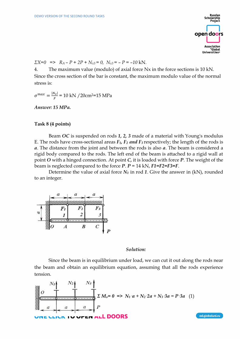
Task 8 (4 points)
Beam ОС is suspended on rods 1, 2, 3 made of a material with Young's modulus E. The rods have cross-sectional areas F1, F2 and F3 respectively; the length of the rods is а. The distance from the joint and between the rods is also а. The beam is considered a rigid body compared to the rods. The left end of the beam is attached to a rigid wall at point O with a hinged connection. At point C, it is loaded with force P. The weight of the beam is neglected compared to the force P. P = 14 kN, F1=F2=F3=F.
Determine the value of axial force N1 in rod 1. Give the answer in (kN), rounded to an integer.
Solution:
Since the beam is in equilibrium under load, we can cut it out along the rods near
the beam and obtain an equilibrium equation, assuming that all the rods experience
tension.
Σ Mo= 0 => N1·a + N2·2a + N3·3a = P·3a (1)

DEMO VERSION OF THE SECOND ROUND TASKS
7
Then we build a deformed system. Beam ОС will rotate on hinge O under force P.
The amount of rotation of the beam is determined by the deformations of rods 1, 2 and 3.
Due to the insignificance of deformations, we can assume that any point of the beam
moves vertically downward.
In the figure, ОС’ demonstrates the position of the beam without load and ОС
shows that under load Р. Accordingly, АА’ is the elongation of rod 1; ВВ’, of rod 2; СС’,
of 3. Now we can write down the geometric similarity of the elongation of the rods.
Δl2 = 2Δl1 и Δl3 = 3Δl1 (2)
Then we express the elongation of rods through forces, lengths, and stiffness.
Δl1 = N1·a / EF
Δl2 = N2·a / EF (3)
Δl3 = N3·a / EF
By replacing expressions for extensions (3) in (2), we obtain:
N2 = 2 N1 и N3 = 3 N1 (4)
Next, we substitute expression (4) into (1)
N1 = 3
14⋅ 𝑃 N2 =
6
14⋅ 𝑃 N3 =
9
14⋅ 𝑃 (5)
By substituting the load value P = 14 kN, we get the amount of force in rod 1: N1
= 3 kN.
Answer: 3 Task 9 (11 points)
A symmetric system of three rods 1, 2 and 3 made from a material with Young's
modulus E has cross-sectional areas F1, F2, and F3 respectively. The length of vertical rod

DEMO VERSION OF THE SECOND ROUND TASKS
8
2 is L. The angles between the rods are the same and equal to φ. The upper ends of the
rods are attached to a rigid wall with a hinged connection, whilst the lower ends are
similarly attached at point A, to which vertical force P is applied. P = 10 kN, F1 = F2 = F3
= F, cos φ = 0.7.
Calculate force N1 in rod 1.
Solution:
Since the system of rods under load P is in equilibrium, we can cut the rods near
node A and obtain equilibrium equations, assuming that all the rods experience tension.
Σ X = 0 => −N1 ·sinφ + N3·sinφ = 0,
and N1 = N3 since the system is symmetrical.
Σ Y = 0 => −P + N1 ·cosφ + N2 + N3·cosφ = 0,
if N1 = N3 , −P + 2N1 ·cosφ + N2 = 0 (1)
DEMO VERSION OF THE SECOND ROUND TASKS
9
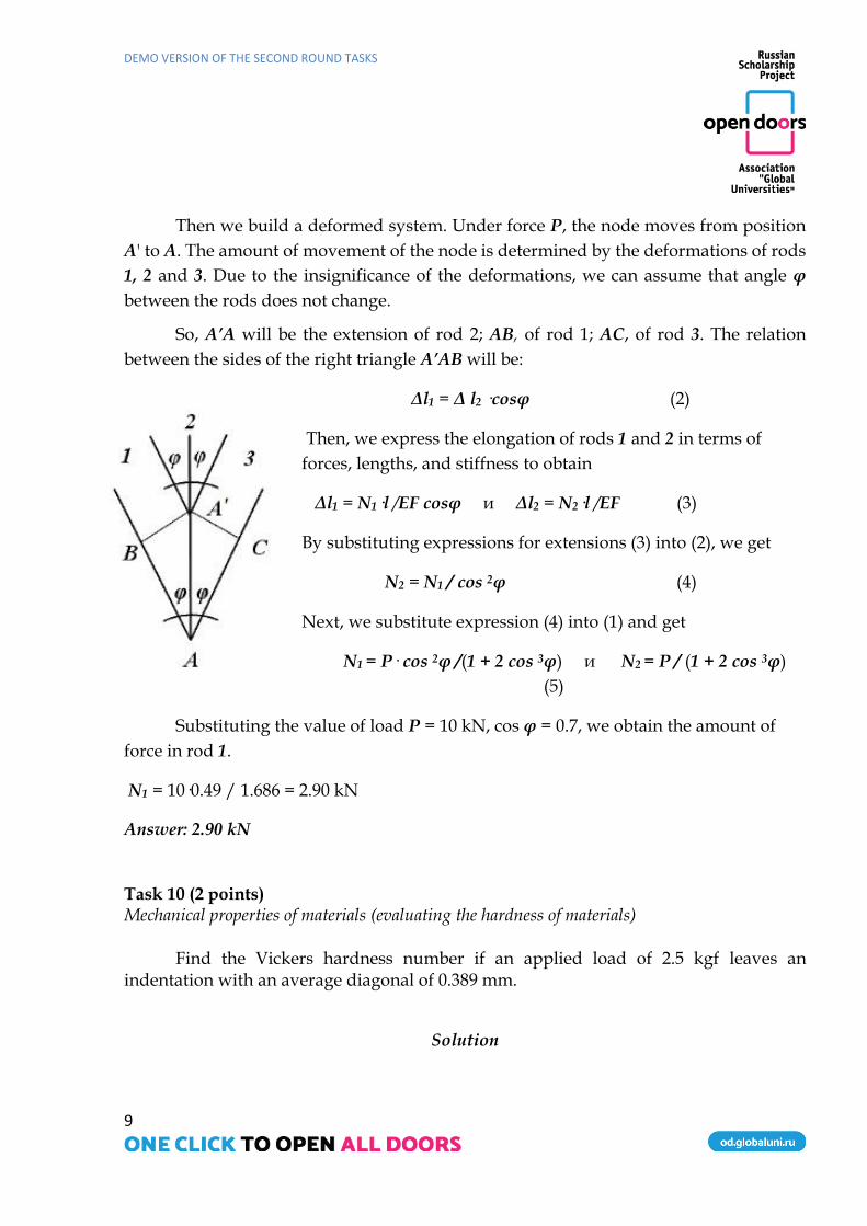
Then we build a deformed system. Under force P, the node moves from position
A' to A. The amount of movement of the node is determined by the deformations of rods
1, 2 and 3. Due to the insignificance of the deformations, we can assume that angle φ
between the rods does not change.
So, A’A will be the extension of rod 2; AB, of rod 1; AC, of rod 3. The relation
between the sides of the right triangle A’AB will be:
Δl1 = Δ l2 ·cosφ (2)
Then, we express the elongation of rods 1 and 2 in terms of
forces, lengths, and stiffness to obtain
Δl1 = N1·l /EF cosφ и Δl2 = N2·l /EF (3)
By substituting expressions for extensions (3) into (2), we get
N2 = N1 / cos 2φ (4)
Next, we substitute expression (4) into (1) and get
N1 = P· cos 2φ /(1 + 2 cos 3φ) и N2 = P / (1 + 2 cos 3φ)
(5)
Substituting the value of load P = 10 kN, cos φ = 0.7, we obtain the amount of
force in rod 1.
N1 = 10·0.49 / 1.686 = 2.90 kN
Answer: 2.90 kN Task 10 (2 points) Mechanical properties of materials (evaluating the hardness of materials)
Find the Vickers hardness number if an applied load of 2.5 kgf leaves an
indentation with an average diagonal of 0.389 mm.
Solution
DEMO VERSION OF THE SECOND ROUND TASKS
10
The Vickers hardness test focuses on the relationship between the depth of penetration of a tetrahedral diamond pyramid (indenter) with a face angle of 136° into the material and the amount of applied force. The surface hardness of the test material can be determined using the formula:
HV = 1.8544 P/d2, kgf/mm2 or hardness units,
where P is the load on the indenter, kgf, d is the average value of indentation diagonals, mm.
We substitute the given values of load applied to the indenter and the average
value of the indentation diagonals into formula (1):
HV = 1.8544 · 2.5 kgf/(0.389 mm)2 = 30,64 kgf/mm2 or 30,64HV
Task 11 (4 points) Heat treatment of materials
Calculate the carbon content in steel needed to obtain a material with martensite
hardness HRCM = 33. What percentage of the area will be occupied by ferrite in the microstructure analysis of the initial material?
Solution:
During quenching, the hardness of steel increases as a martensitic structure is formed. Although the hardness of martensite depends on many parameters, the carbon content in steel is the most influential factor. To determine the carbon content in an alloy by the hardness of the resulting martensite after quenching, we can use the following empirical formula. (It is applied when calculating the carbon content in steels with martensite hardness in the range of 30-65HRCM.)
С = 13.9 – 1.35855156·HRCM + 0.0487592·HRCM2 – 0.0007566·HRCM3 + 0.00000432·HRCM4, (2)
where C is the carbon content, %, HRCM is the required hardness of martensite in hardness units.
To determine carbon content in steel at a given hardness of martensite, we use
formula (2):
С = 13.9 – 1.35855156·33 + 0.0487592·332 – 0.0007566·333 + 0.00000432·334 = 0.1%
DEMO VERSION OF THE SECOND ROUND TASKS
11
The steel contains 0.1 percent of carbon, i.e. it is a hypoeutectoid steel whose
microstructure consists of ferrite and pearlite. To find the area occupied by perlite, we
apply the following formula:
P = C·100/0.8 = 0.1·100/0.8 = 12.5%.
Consequently, the proportion of ferrite is F = 100 – P = 87.5%. Task 12 (11 points) Reading phase diagrams of a two-component system
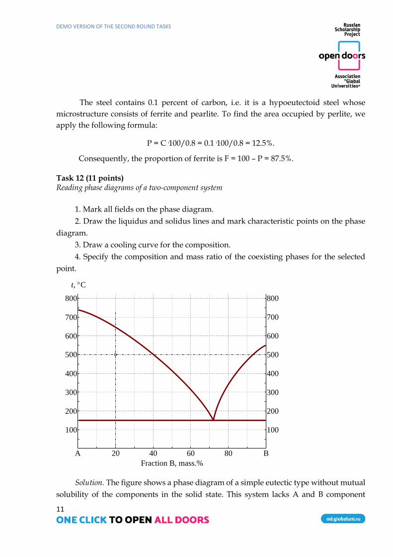
1. Mark all fields on the phase diagram.
2. Draw the liquidus and solidus lines and mark characteristic points on the phase
diagram.
3. Draw a cooling curve for the composition.
4. Specify the composition and mass ratio of the coexisting phases for the selected
point.
Fraction B, mass.%
100
200
300
400
600
700
80 60 40 20
t, C
B A
100
200
300
400
500
600
700
800 800
500
Solution. The figure shows a phase diagram of a simple eutectic type without mutual
solubility of the components in the solid state. This system lacks A and B component
DEMO VERSION OF THE SECOND ROUND TASKS
12
compounds.
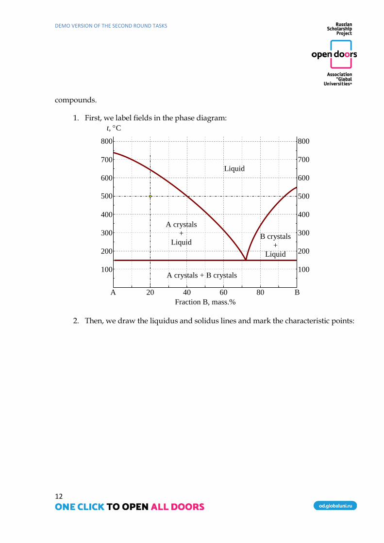
1. First, we label fields in the phase diagram:
Fraction B, mass.%
100
200
300
400
600
700
80 60 40 20
t, C
B A
100
200
300
400
500
600
700
800 800
500
Liquid
A crystals
+
Liquid B crystals
+
Liquid
A crystals + B crystals
2. Then, we draw the liquidus and solidus lines and mark the characteristic points:

DEMO VERSION OF THE SECOND ROUND TASKS
13
Fraction B, mass.%
100
200
300
400
600
700
80 60 40 20
t, C
B A
100
200
300
400
500
600
700
800 800
500 Liquidus line
Solidus line
Tmelting_A
Tmelting_B
Eu
tect
ic
Liquid
A crystals
+
Liquid B crystals
+
Liquid
A crystals + B crystals
3. The cooling curve for the composition will look as follows:
Fraction B, mass.%
100
200
300
400
600
700
80 60 40 20
t, C
B A
100
200
300
400
500
600
700
800 800
500
100
200
300
400
600
700
t, C
Cooling curve of a composition
corresponding to 20 mass.% B
800
500
Tmelting_A
Tплавления_A
Liquid
Tliquidus = 690 C
Teutectic
=150 C
A crystals
+
Liquid
A crystals
+
B crystals
L → L + A
L + A → L + A + B
Liquid
A crystals
+
Liquid B crystals
+
Liquid
A crystals + B crystals
Liquidus line
Solidus line
Tmelting_A
Tmelting_B
Eu
tect
ic
4. For the imaging point, we identify the composition and mass ratio of coexisting
phases. The imaging point lies in a two-phase field in which crystals of component
DEMO VERSION OF THE SECOND ROUND TASKS
14
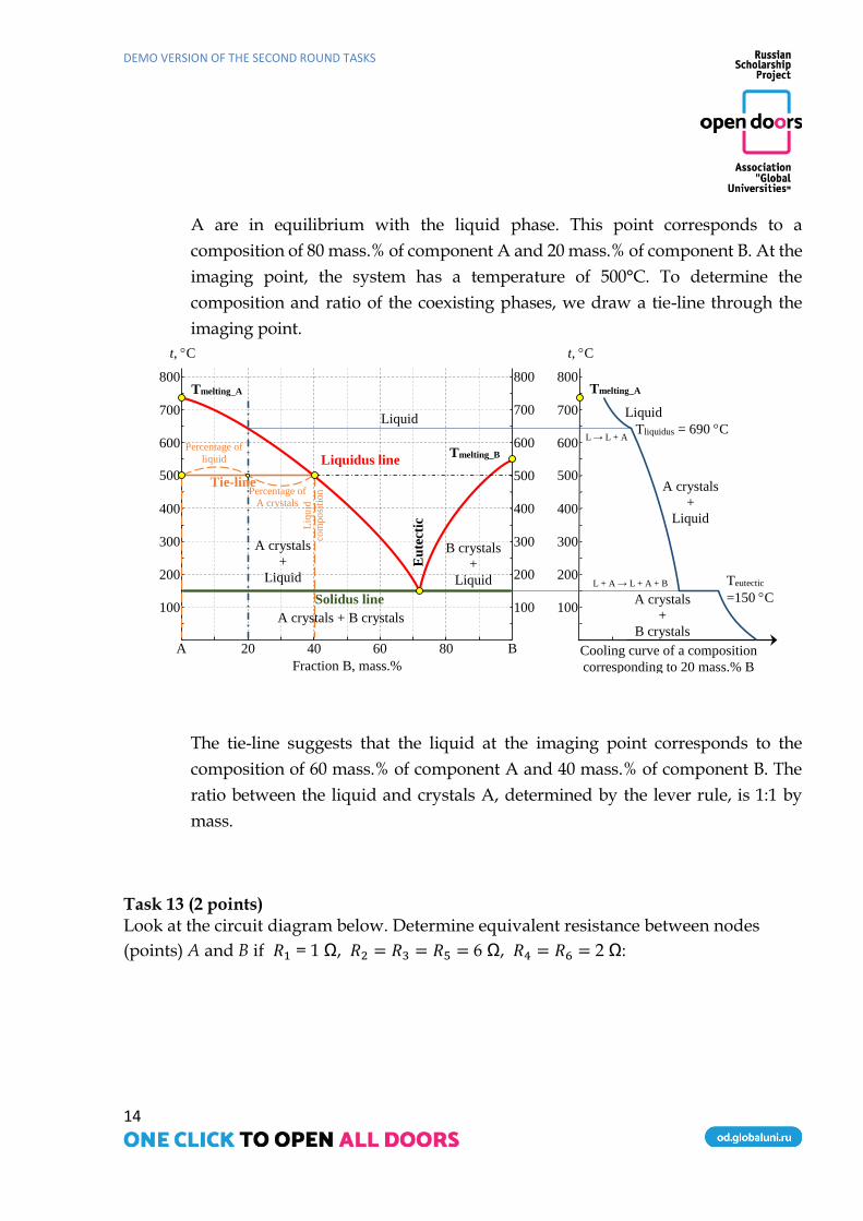
A are in equilibrium with the liquid phase. This point corresponds to a
composition of 80 mass.% of component A and 20 mass.% of component B. At the
imaging point, the system has a temperature of 500°C. To determine the
composition and ratio of the coexisting phases, we draw a tie-line through the
imaging point.
Fraction B, mass.%
100
200
300
400
600
700
80 60 40 20
t, C
B A
100
200
300
400
500
600
700
800 800
500
100
200
300
400
600
700
t, C
800
500
Tплавления_A
Tie-line
Liq
uid
com
po
siti
on
Percentage of
liquid
Percentage of
A crystals
Liquid
A crystals
+
Liquid
B crystals
+
Liquid
A crystals + B crystals
Liquidus line
Solidus line
Tmelting_A
Tmelting_B
Eu
tect
ic
Cooling curve of a composition
corresponding to 20 mass.% B
Tmelting_A
Liquid
Tliquidus = 690 C
Teutectic
=150 C
A crystals
+
Liquid
A crystals
+
B crystals
L → L + A
L + A → L + A + B
The tie-line suggests that the liquid at the imaging point corresponds to the
composition of 60 mass.% of component A and 40 mass.% of component B. The
ratio between the liquid and crystals A, determined by the lever rule, is 1:1 by
mass.
Task 13 (2 points) Look at the circuit diagram below. Determine equivalent resistance between nodes
(points) A and B if 𝑅1 = 1 Ω, 𝑅2 = 𝑅3 = 𝑅5 = 6 Ω, 𝑅4 = 𝑅6 = 2 Ω:

DEMO VERSION OF THE SECOND ROUND TASKS
15
А) 1 Ω
B) 0.8 Ω
C) 1.25 Ω
D) 0
E) 23 Ω
Task 14 (4 points)

DEMO VERSION OF THE SECOND ROUND TASKS
16
Look at the circuit diagram below. The source voltage is 𝐸 = 𝑐𝑜𝑛𝑠𝑡. Choose one possible
form of the obtained algebraic equation of the circuit:
A) 𝑠2 + 1 = 0
B)𝑠2 − 𝑠 − 1 = 0
C)𝑠2 + 𝑠 + 1 = 0
D) 𝑠3 + 𝑠2 + 𝑠 + 1 = 0
E)𝑠2 + 𝑠 − 1 = 0
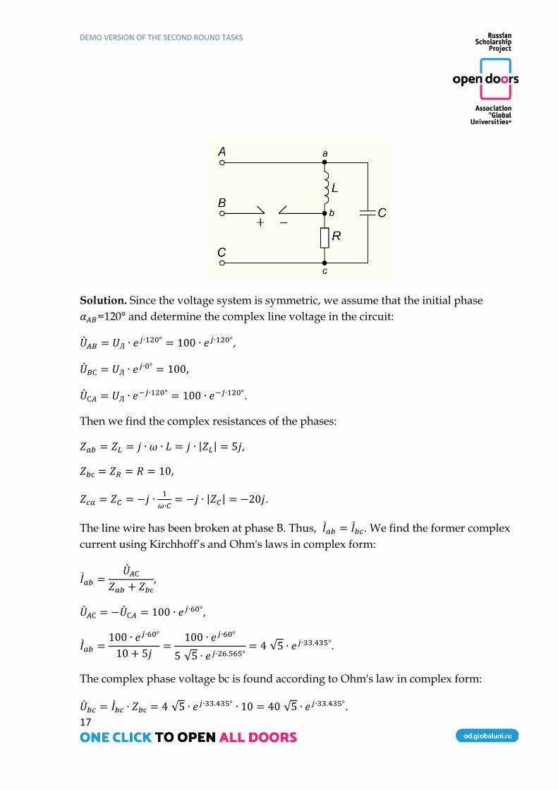
Task 15 (10 points) Look at the circuit diagram below. The three-phase source is symmetrical, and the
phase sequence is clockwise. The line voltage is 100𝑉. Line wire breakage has occurred
at phase B. Determine the voltage 𝑢𝐵𝑏(𝑡) if 𝑅= 10 Ω, 𝑍𝐶 ∨ 20Ω, 𝑍𝐿 ∨ 5Ω.
DEMO VERSION OF THE SECOND ROUND TASKS
17
Solution. Since the voltage system is symmetric, we assume that the initial phase
𝛼𝐴𝐵=120° and determine the complex line voltage in the circuit:
𝐴𝐵 = 𝑈Л ∙ 𝑒𝑗∙120° = 100 ∙ 𝑒𝑗∙120°,
𝐵С = 𝑈Л ∙ 𝑒𝑗∙0° = 100,
С𝐴 = 𝑈Л ∙ 𝑒−𝑗∙120° = 100 ∙ 𝑒−𝑗∙120°.
Then we find the complex resistances of the phases:
𝑍𝑎𝑏 = 𝑍𝐿 = 𝑗 ∙ 𝜔 ∙ 𝐿 = 𝑗 ∙ |𝑍𝐿| = 5𝑗,
𝑍𝑏с = 𝑍𝑅 = 𝑅 = 10,
𝑍𝑐𝑎 = 𝑍𝐶 = −𝑗 ∙1
𝜔∙𝐶= −𝑗 ∙ |𝑍𝐶| = −20𝑗.
The line wire has been broken at phase B. Thus, 𝐼𝑎𝑏 = 𝐼𝑏𝑐. We find the former complex
current using Kirchhoff’s and Ohm's laws in complex form:
𝐼𝑎𝑏 =𝐴С
𝑍𝑎𝑏 + 𝑍𝑏с,
𝐴С = −С𝐴 = 100 ∙ 𝑒𝑗∙60°,
𝐼𝑎𝑏 =100 ∙ 𝑒𝑗∙60°
10 + 5𝑗=
100 ∙ 𝑒𝑗∙60°
5 √5 ∙ 𝑒𝑗∙26.565°= 4 √5 ∙ 𝑒𝑗∙33.435°.
The complex phase voltage bc is found according to Ohm's law in complex form:
𝑏𝑐 = 𝐼𝑏𝑐 ∙ 𝑍𝑏с = 4 √5 ∙ 𝑒𝑗∙33.435° ∙ 10 = 40 √5 ∙ 𝑒𝑗∙33.435°.

DEMO VERSION OF THE SECOND ROUND TASKS
18
Using Kirchhoff’ voltage law in complex form, we obtain the complex voltage 𝐵𝑏
𝐵𝑏 = 𝐵С − 𝑏𝑐 = 100 − 40 √5 ∙ 𝑒𝑗∙33.435° ≈ 25.359 − 49.282𝑗 = 55.424 ∙ 𝑒−𝑗∙62.771°
Thus, 𝑢𝐵𝑏(𝑡) = 78.381 ∙ 𝑐𝑜𝑠(𝜔 ∙ 𝑡 − 62.771°)
Answer: 𝑢𝐵𝑏(𝑡) = 78.381 ∙ 𝑐𝑜𝑠(𝜔 ∙ 𝑡 − 62.771°), 𝑉
Task 16 (1 point)
Which of the symbols represents a Zener diode?
1. VD1
2. VD2
3. VD3
4. VD4
5. VD5
6. VD6
Task 17 (4 points)
The value of direct current flowing through a rectifier diode increased from 3mA to 16mA
when the direct voltage changed from 0.2 V to 0.4 V.
Calculate the differential resistance of this rectifier diode.
DEMO VERSION OF THE SECOND ROUND TASKS
19
1.15,38𝑘Ω
2.15,38Ω
3.25,00Ω
4.25,00МΩ
Solution: 𝑅𝑑𝑖𝑓𝑓 =𝛥𝑈𝑑𝑖𝑟𝑒𝑐𝑡
𝛥𝐼𝑑𝑖𝑟𝑒𝑐𝑡=
0,4−0,2
(16−3)∗10−3= 15,38Ω.
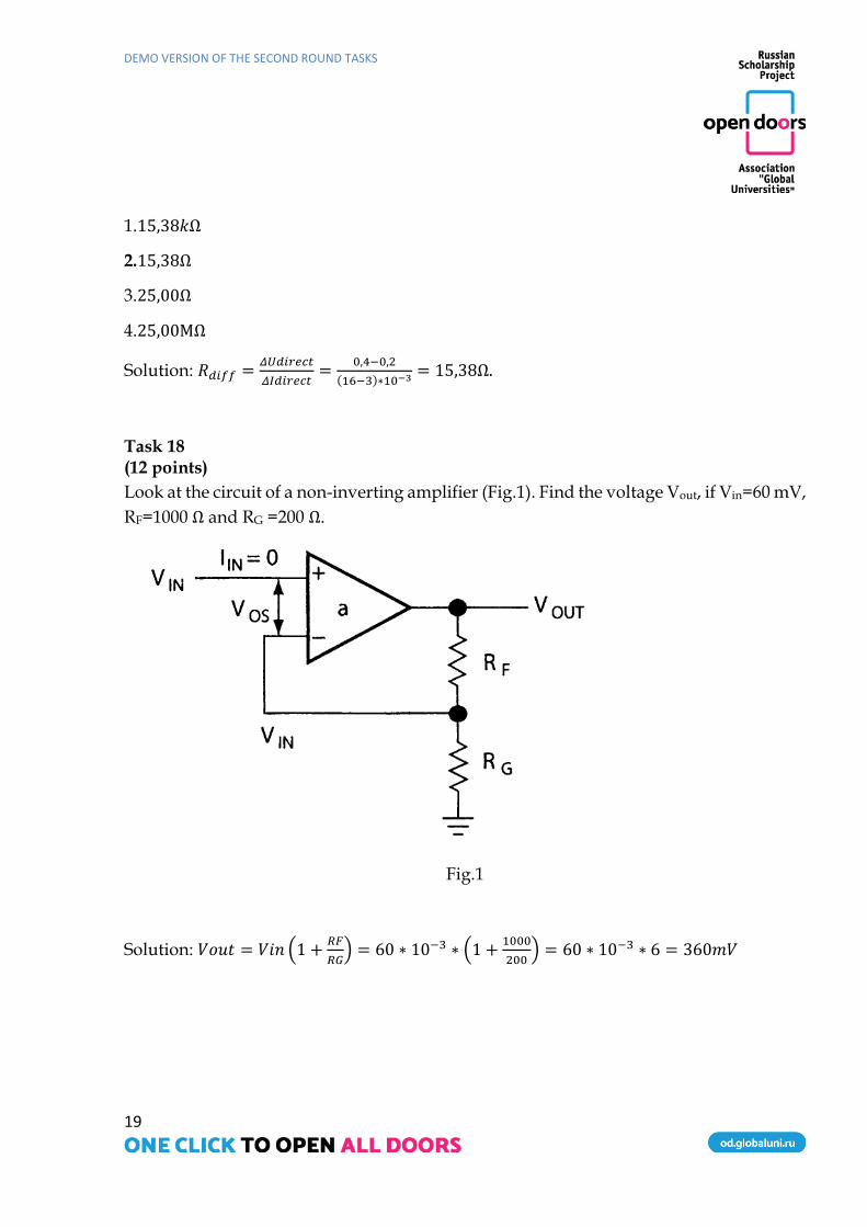
Task 18 (12 points)
Look at the circuit of a non-inverting amplifier (Fig.1). Find the voltage Vout, if Vin=60 mV,
RF=1000 Ω and RG =200 Ω.
Fig.1
Solution: 𝑉𝑜𝑢𝑡 = 𝑉𝑖𝑛 (1 +𝑅𝐹
𝑅𝐺) = 60 ∗ 10−3 ∗ (1 +
1000
200) = 60 ∗ 10−3 ∗ 6 = 360𝑚𝑉