demand defrost control board kit model ... defrost control board kit model 03109137000 for models:...
TRANSCRIPT
DEMAND DEFROST CONTROL BOARD KIT MODEL 03109137000FOR MODELS: YZB, HL3B, HC3B YZE, HC5B, & HL5B SERIES
ACCESSORY KIT INSTALLATION INSTRUCTIONS035-20734-001 Rev. A (0405)
Unitary Products Group
REQUIRED CONTROL SETUPJumper SettingsThe jumper settings on the new control board must be set atthe time of installation to insure proper system operation. It iseasiest to set the jumpers before actual installation of thecontrol board, but it is also possible after the control board isinstalled in the control box.1. If hot heat pump configuration is desired, change HOT
HEAT PUMP jumper to ON position. This is described inmore detail under the Heating Operation section.
2. If installation includes a fossil fuel furnace, changeFFUEL jumper to ON position. This is described in moredetail under the Fossil Fuel Jumper section.
3. Set low temperature cutout (LTCO) and balance point(BP) jumpers as desired. This is described in more detailunder the LTCO and BP paragraph.
4. Set defrost curve jumper, as shown below and in Table 1.Defrost curves are described in more detail under theDefrost Operation section.
5. Set Y2 lock jumper as desired for YZE/HC5B/HL5B mod-els. This is described in more detail under “Y2 LOCK”heading of this document.
6. Set switch point jumpers desired for YZE/HC5B/HL5Bmodels. This is described in more detail under “SWITCHPOINT” heading of this document.
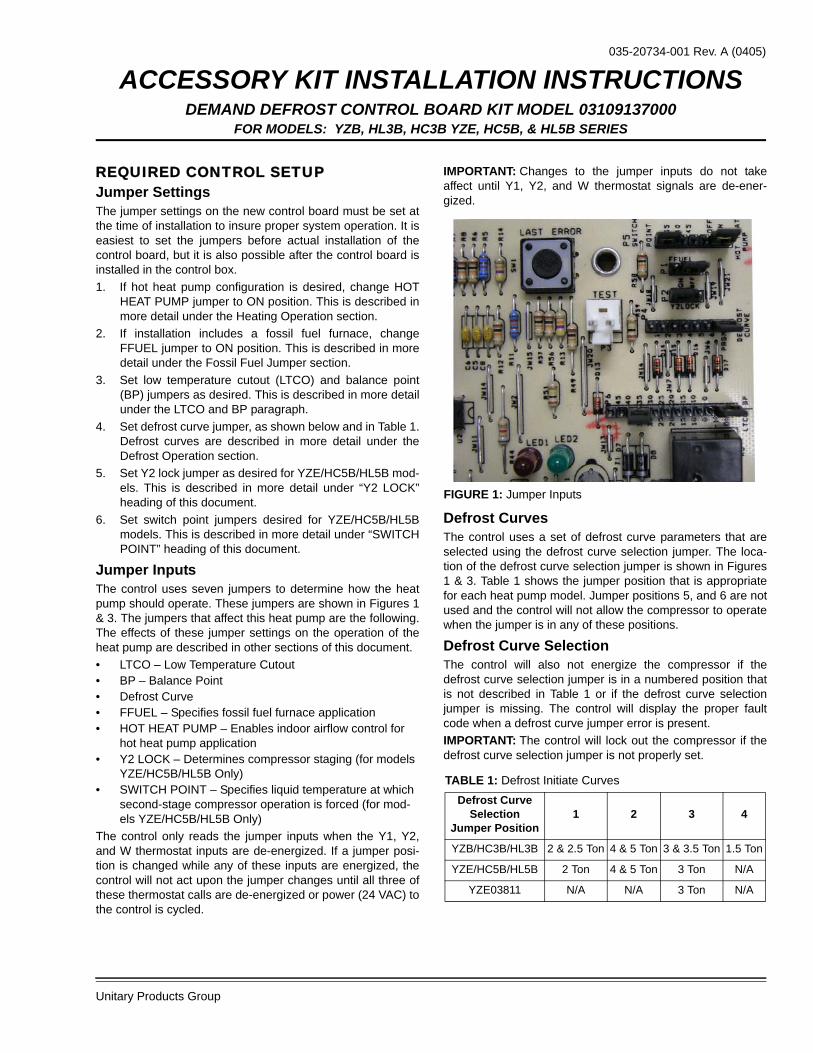
Jumper InputsThe control uses seven jumpers to determine how the heatpump should operate. These jumpers are shown in Figures 1& 3. The jumpers that affect this heat pump are the following.The effects of these jumper settings on the operation of theheat pump are described in other sections of this document.• LTCO – Low Temperature Cutout• BP – Balance Point• Defrost Curve• FFUEL – Specifies fossil fuel furnace application• HOT HEAT PUMP – Enables indoor airflow control for
hot heat pump application• Y2 LOCK – Determines compressor staging (for models
YZE/HC5B/HL5B Only)• SWITCH POINT – Specifies liquid temperature at which
second-stage compressor operation is forced (for mod-els YZE/HC5B/HL5B Only)
The control only reads the jumper inputs when the Y1, Y2,and W thermostat inputs are de-energized. If a jumper posi-tion is changed while any of these inputs are energized, thecontrol will not act upon the jumper changes until all three ofthese thermostat calls are de-energized or power (24 VAC) tothe control is cycled.
IMPORTANT: Changes to the jumper inputs do not takeaffect until Y1, Y2, and W thermostat signals are de-ener-gized.
Defrost CurvesThe control uses a set of defrost curve parameters that areselected using the defrost curve selection jumper. The loca-tion of the defrost curve selection jumper is shown in Figures1 & 3. Table 1 shows the jumper position that is appropriatefor each heat pump model. Jumper positions 5, and 6 are notused and the control will not allow the compressor to operatewhen the jumper is in any of these positions.
Defrost Curve SelectionThe control will also not energize the compressor if thedefrost curve selection jumper is in a numbered position thatis not described in Table 1 or if the defrost curve selectionjumper is missing. The control will display the proper faultcode when a defrost curve jumper error is present.IMPORTANT: The control will lock out the compressor if thedefrost curve selection jumper is not properly set.
FIGURE 1: Jumper Inputs
TABLE 1: Defrost Initiate CurvesDefrost Curve
Selection Jumper Position
1 2 3 4
YZB/HC3B/HL3B 2 & 2.5 Ton 4 & 5 Ton 3 & 3.5 Ton 1.5 Ton
YZE/HC5B/HL5B 2 Ton 4 & 5 Ton 3 Ton N/A
YZE03811 N/A N/A 3 Ton N/A
035-20734-001 Rev. A (0405)
2 Unitary Products Group
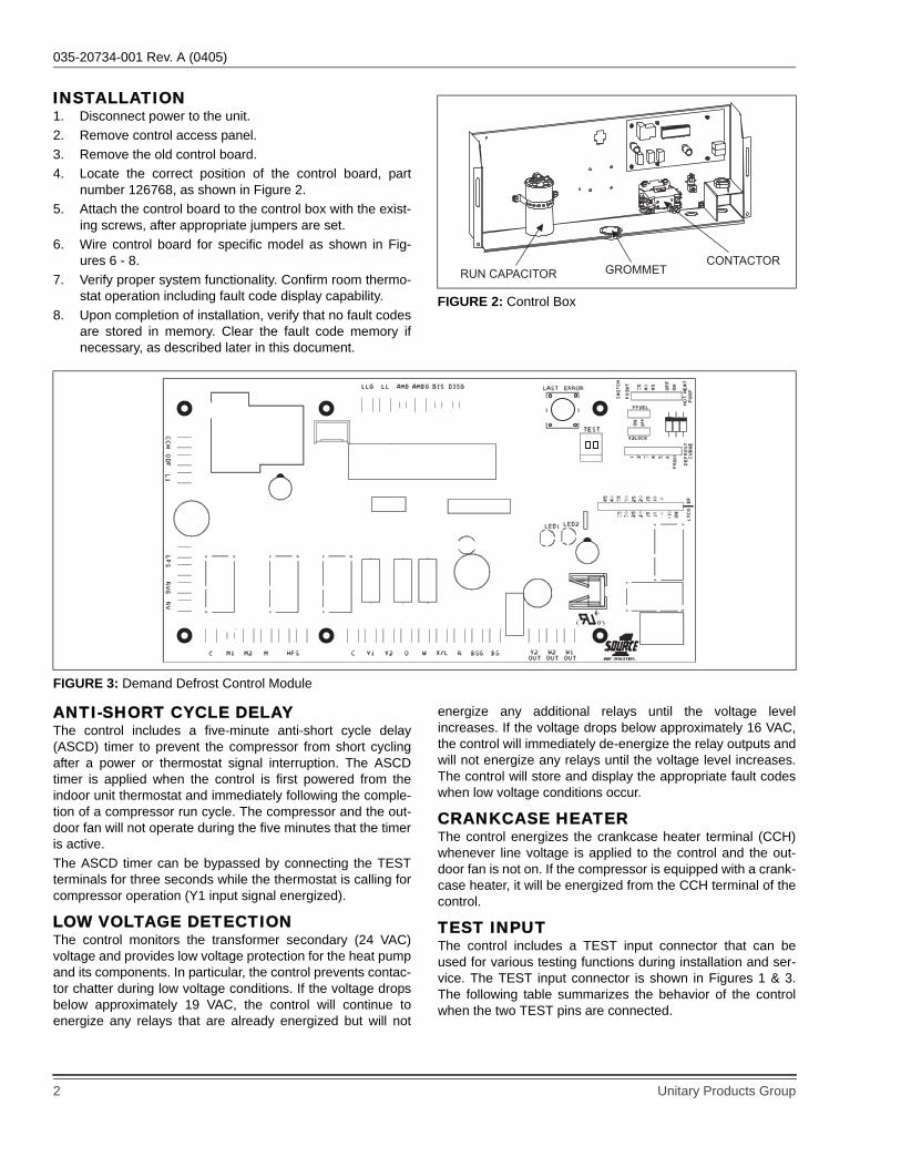
INSTALLATION1. Disconnect power to the unit.2. Remove control access panel.3. Remove the old control board. 4. Locate the correct position of the control board, part
number 126768, as shown in Figure 2.5. Attach the control board to the control box with the exist-
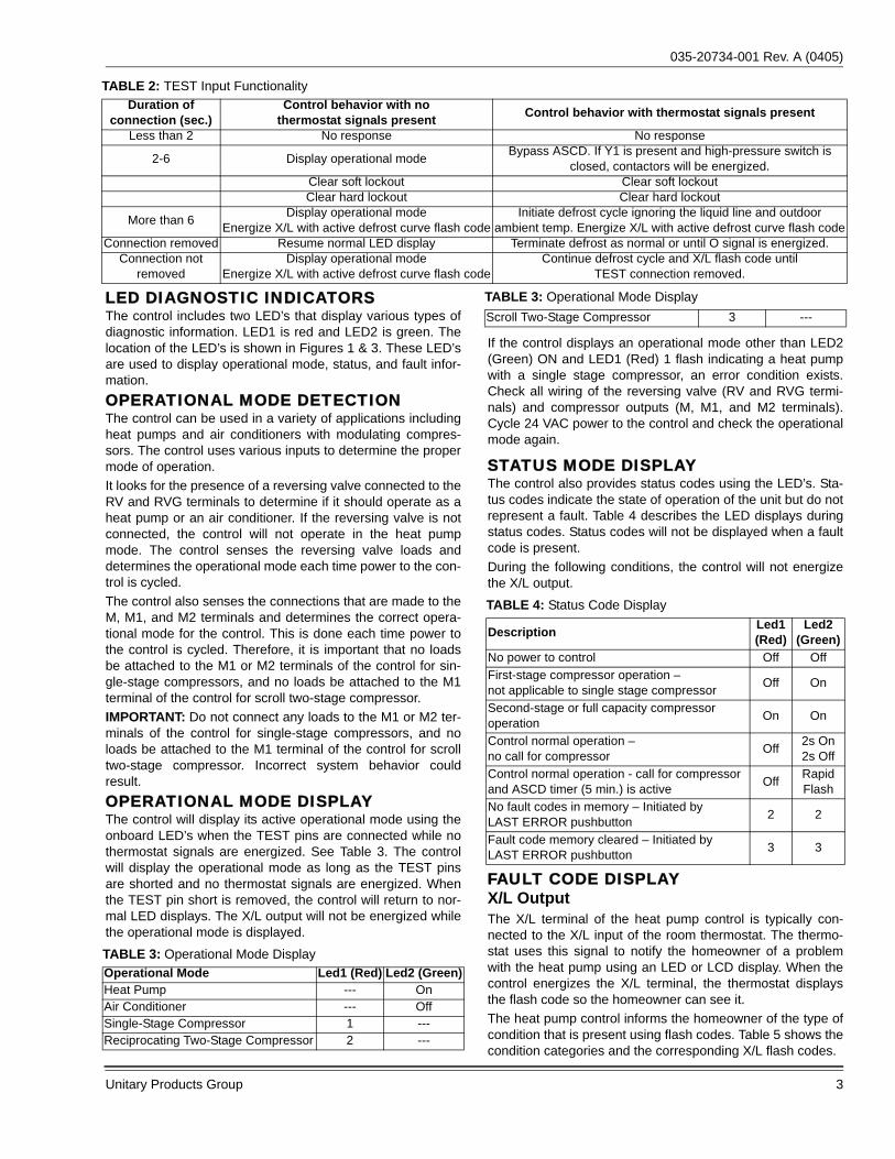
ing screws, after appropriate jumpers are set.6. Wire control board for specific model as shown in Fig-
ures 6 - 8.7. Verify proper system functionality. Confirm room thermo-
stat operation including fault code display capability.8. Upon completion of installation, verify that no fault codes
are stored in memory. Clear the fault code memory ifnecessary, as described later in this document.
ANTI-SHORT CYCLE DELAYThe control includes a five-minute anti-short cycle delay(ASCD) timer to prevent the compressor from short cyclingafter a power or thermostat signal interruption. The ASCDtimer is applied when the control is first powered from theindoor unit thermostat and immediately following the comple-tion of a compressor run cycle. The compressor and the out-door fan will not operate during the five minutes that the timeris active.The ASCD timer can be bypassed by connecting the TESTterminals for three seconds while the thermostat is calling forcompressor operation (Y1 input signal energized).
LOW VOLTAGE DETECTIONThe control monitors the transformer secondary (24 VAC)voltage and provides low voltage protection for the heat pumpand its components. In particular, the control prevents contac-tor chatter during low voltage conditions. If the voltage dropsbelow approximately 19 VAC, the control will continue toenergize any relays that are already energized but will not
energize any additional relays until the voltage levelincreases. If the voltage drops below approximately 16 VAC,the control will immediately de-energize the relay outputs andwill not energize any relays until the voltage level increases.The control will store and display the appropriate fault codeswhen low voltage conditions occur.
CRANKCASE HEATERThe control energizes the crankcase heater terminal (CCH)whenever line voltage is applied to the control and the out-door fan is not on. If the compressor is equipped with a crank-case heater, it will be energized from the CCH terminal of thecontrol.
TEST INPUTThe control includes a TEST input connector that can beused for various testing functions during installation and ser-vice. The TEST input connector is shown in Figures 1 & 3.The following table summarizes the behavior of the controlwhen the two TEST pins are connected.
FIGURE 2: Control Box
RUN CAPACITOR
CONTACTORGROMMET
FIGURE 3: Demand Defrost Control Module
035-20734-001 Rev. A (0405)
Unitary Products Group 3
LED DIAGNOSTIC INDICATORSThe control includes two LED’s that display various types ofdiagnostic information. LED1 is red and LED2 is green. Thelocation of the LED’s is shown in Figures 1 & 3. These LED’sare used to display operational mode, status, and fault infor-mation.OPERATIONAL MODE DETECTIONThe control can be used in a variety of applications includingheat pumps and air conditioners with modulating compres-sors. The control uses various inputs to determine the propermode of operation.It looks for the presence of a reversing valve connected to theRV and RVG terminals to determine if it should operate as aheat pump or an air conditioner. If the reversing valve is notconnected, the control will not operate in the heat pumpmode. The control senses the reversing valve loads anddetermines the operational mode each time power to the con-trol is cycled.The control also senses the connections that are made to theM, M1, and M2 terminals and determines the correct opera-tional mode for the control. This is done each time power tothe control is cycled. Therefore, it is important that no loadsbe attached to the M1 or M2 terminals of the control for sin-gle-stage compressors, and no loads be attached to the M1terminal of the control for scroll two-stage compressor.IMPORTANT: Do not connect any loads to the M1 or M2 ter-minals of the control for single-stage compressors, and noloads be attached to the M1 terminal of the control for scrolltwo-stage compressor. Incorrect system behavior couldresult.OPERATIONAL MODE DISPLAYThe control will display its active operational mode using theonboard LED’s when the TEST pins are connected while nothermostat signals are energized. See Table 3. The controlwill display the operational mode as long as the TEST pinsare shorted and no thermostat signals are energized. Whenthe TEST pin short is removed, the control will return to nor-mal LED displays. The X/L output will not be energized whilethe operational mode is displayed.
If the control displays an operational mode other than LED2(Green) ON and LED1 (Red) 1 flash indicating a heat pumpwith a single stage compressor, an error condition exists.Check all wiring of the reversing valve (RV and RVG termi-nals) and compressor outputs (M, M1, and M2 terminals).Cycle 24 VAC power to the control and check the operationalmode again.
STATUS MODE DISPLAYThe control also provides status codes using the LED’s. Sta-tus codes indicate the state of operation of the unit but do notrepresent a fault. Table 4 describes the LED displays duringstatus codes. Status codes will not be displayed when a faultcode is present.During the following conditions, the control will not energizethe X/L output.
FAULT CODE DISPLAYX/L OutputThe X/L terminal of the heat pump control is typically con-nected to the X/L input of the room thermostat. The thermo-stat uses this signal to notify the homeowner of a problemwith the heat pump using an LED or LCD display. When thecontrol energizes the X/L terminal, the thermostat displaysthe flash code so the homeowner can see it.The heat pump control informs the homeowner of the type ofcondition that is present using flash codes. Table 5 shows thecondition categories and the corresponding X/L flash codes.
TABLE 2: TEST Input FunctionalityDuration of
connection (sec.)Control behavior with no
thermostat signals present Control behavior with thermostat signals present
Less than 2 No response No response
2-6 Display operational mode Bypass ASCD. If Y1 is present and high-pressure switch is closed, contactors will be energized.
Clear soft lockout Clear soft lockoutClear hard lockout Clear hard lockout
More than 6 Display operational modeEnergize X/L with active defrost curve flash code
Initiate defrost cycle ignoring the liquid line and outdoor ambient temp. Energize X/L with active defrost curve flash code
Connection removed Resume normal LED display Terminate defrost as normal or until O signal is energized.Connection not
removedDisplay operational mode
Energize X/L with active defrost curve flash codeContinue defrost cycle and X/L flash code until
TEST connection removed.
TABLE 3: Operational Mode DisplayOperational Mode Led1 (Red) Led2 (Green)Heat Pump --- OnAir Conditioner --- OffSingle-Stage Compressor 1 ---Reciprocating Two-Stage Compressor 2 ---
Scroll Two-Stage Compressor 3 ---
TABLE 4: Status Code Display
Description Led1(Red)
Led2(Green)
No power to control Off OffFirst-stage compressor operation – not applicable to single stage compressor Off On
Second-stage or full capacity compressor operation On On
Control normal operation – no call for compressor Off 2s On
2s OffControl normal operation - call for compressor and ASCD timer (5 min.) is active Off Rapid
FlashNo fault codes in memory – Initiated by LAST ERROR pushbutton 2 2
Fault code memory cleared – Initiated by LAST ERROR pushbutton 3 3
TABLE 3: Operational Mode Display
035-20734-001 Rev. A (0405)
4 Unitary Products Group
The control will continue to energize the X/L output for faultcodes having an X/L code of 4 flashes even after the thermo-stat calls are removed. The control does this to notify theinstaller or homeowner that a significant problem with the wir-ing or system configuration is present and needs to be cor-rected.The control will continue to energize the X/L output until thecondition that caused the fault condition no longer exists.
LED DisplayThe control will display any fault code that is currently activeusing the LED’s. The control will display the fault code, pausetwo seconds, and display the fault again. The control will con-tinue the fault code display until the condition that caused thefault code no longer exists. If multiple fault codes are presentat the same time, the control will display only the most recentfault. The other active errors may be accessed from memoryusing the LAST ERROR pushbutton.Operational Fault CodesTable 6 shows the operational faults that the control candetect. The control displays this type of error by flashingLED1 (Red) only. LED1 (Green) is not energized. Thesefaults typically occur when the heat pump has been operatingand a problem occurs.
Sensor or Switch Fault CodesTable 7 shows the faults that the control can detect when aproblem is present with a sensor or switch. The control dis-plays this type of error by energizing LED1 (Red) constantlyand flashing LED2 (Green). These faults typically occur whenthe heat pump has been operating and a problem occurs witha sensor or its wiring. These faults could also occur duringinstallation as the heat pump is configured.
Wiring Related Fault CodesTable 8 shows the faults that the control can detect when aproblem is present with the system wiring or jumper configu-rations. The control displays this type of error by flashingLED1 (Red) and energizing LED2 (Green) constantly. Thesefaults typically occur when the heat pump is first installed orwhen a system component such as the room thermostat orindoor unit is replaced or rewired.
TABLE 5: X/L Output CategoriesCondition Category X/LSoft Lockout – Reset with interruption of thermostat call following correction of fault condition
2 flashes
Hard Lockout – Reset by cycling power to system 3 flashesWiring, sensor or control setting related error 4 flashes
TABLE 6: Operational Fault Codes
Description Led1 (Red)
Led2 (Green) X/L
Operational FaultsControl Failure that still allows fault code output On Off 4
if possibleHigh-pressure switch fault (not in lockout yet) 1 Off OFF
High-pressure switch lockout (last mode of operation was heat pump) 2 Off 2 (soft)
3 (hard)High-pressure switch lockout (last mode of operation was defrost) 3 Off 2 (soft)
3 (hard)
Low-pressure switch lockout 4 Off 2 (soft) 3 (hard)
Low Voltage (< 19 VAC) preventing further relay outputs 5 Off Off
Low Voltage (< 16 VAC) stopped current relay outputs 6 Off Off
Pipe Freeze Protection Timer expiration 7 Off 4
TABLE 7: Sensor or Switch Fault Codes
Description LED1 (Red)
LED2 (Green) X/L
Required Sensor or Switch FaultsOutdoor ambient sensor failure (short) ON 1 2 (soft)Outdoor ambient sensor failure (open) ON 2 2 (soft)Liquid line sensor failure (short) ON 3 2 (soft)Liquid line sensor failure (open) ON 4 2 (soft)Optional Discharge Line Sensor Faults
High discharge line temperature ON 5 2 (soft)3 (hard)
Low discharge line temperature ON 6 2 (soft) 3 (hard)
Discharge line sensor failure (short) ON 7 2 (soft)Optional Bonnet Sensor FaultsBonnet sensor failure (short) ON 8 4Fossil Fuel Mode setting error (FFUEL jumper in OFF position but bonnet sensor present)
ON 9 4
TABLE 8: Wiring Related Fault Codes
Description LED1 (Red)
LED2 (Green) X/L
Wiring Related FaultsCompressor Contactor Miswire 1 ON 4Y2 present without Y1 2 ON 4Y1 and W present without Y2 in two stage mode 3 ON 4
O signal received in AC mode 4 ON 4W signal received in AC mode 5 ON 4W and O signal received in AC mode 6 ON 4W and O signal received in HP mode 7 ON 4Defrost Curve Jumper Error (Invalid jumper setting preventing compressor operation)
8 ON 4

035-20734-001 Rev. A (0405)
Unitary Products Group 5
FAULT CODE MEMORYDisplaying Stored Fault CodesThe control will store up to five fault codes in memory. If morethan five faults occur, the five most recent fault codes willremain in memory. The stored faults can be displayed bydepressing the LAST ERROR pushbutton for one to five sec-onds while no thermostat inputs to the control are energized.See Figures 1 & 3 for the location of the pushbutton. Sincesome room thermostats energize the O signal even when notcalling for compressor operation, turn the room thermostat tothe SYSTEM OFF setting when displaying fault codes.When the LAST ERROR pushbutton is depressed andreleased, the control will display the stored fault codes begin-ning with the most recent. The control will display the mostrecent fault code, pause two seconds, and display the nextfault code. The control will display the stored error codes andthen return to the normal LED status display mode. Thestored fault codes can be displayed again by depressing thepushbutton again. When the control displays the fault codeswith the onboard LED’s, it will also energize the X/L outputwith the corresponding flash code. The X/L output signal canbe observed at the room thermostat or at the control using a24VAC LED test device connected to the X/L terminal.If the control has no fault codes stored in memory, it will flashboth LED’s twice simultaneously. If a thermostat signal isenergized while the control is displaying the stored errorcodes, the control will stop displaying the stored error codesand resume normal operation.
Clearing Fault Code MemoryOnce the stored fault codes have been displayed andrecorded, the installer should clear the stored fault codesfrom the control’s memory. This practice will enable bettertroubleshooting and diagnosis of system problems. If thestored fault codes are not cleared after the cause of the prob-lem has been resolved, a service technician doing a later ser-vice call may not know that the fault codes in the memorywere caused by a problem that has already been fixed. Thetechnician may waste time trying to fix a condition that nolonger exists. Therefore, it is very important to always clearthe fault code memory after the unit is installed and runningproperly following a service call.IMPORTANT: Always clear the fault code memory afterresolving the condition that caused the fault code. To clear the fault code memory, depress the LAST ERRORpushbutton for longer than 5 seconds. The control will flashboth LED’s three times to indicate that the memory has beencleared. To confirm that the memory has been cleared,depress the LAST ERROR pushbutton for one to five sec-onds. The control will flash both LED’s twice to indicate thatno faults are stored in memory.
LOCKOUT MODESSoft LockoutThe control will cause a soft lockout during the following con-ditions. Detailed descriptions of the conditions required forthe control to enter the soft lockout mode are contained inother sections of this document. 1. High-pressure switch
a. Two openings within six hours2. Low-pressure switch
a. One opening of the switch for more than five sec-onds except under certain conditions.
3. High discharge temperature (with optional dischargesensor)a. Temperature reading exceeds 263F
4. Low discharge temperature (with optional discharge sen-sor)a. Temperature reading does not reach 90F following
timer expiration under certain conditions.During the soft lockout mode, the control will do the following.1. De-energize the compressor2. If in heating mode, the control will energize auxiliary heat
as if the outdoor ambient temperature was below theLTCO setting.
3. Energize the LED and X/L outputs with the appropriateflash codes
4. Store the appropriate fault code in memory.The control will reset the soft lockout condition when any ofthe following occur following removal of the fault condition.1. Power is cycled to the R or Y1 inputs of the control. This
will cause the soft lockout condition to be reset when thethermostat is satisfied or when the thermostat is set toSYSTEM OFF and back to HEAT or COOL mode.
2. The TEST terminals are shorted for more than two sec-onds.
When the soft lockout condition is reset, the control will stopdisplaying the fault code and will respond to thermostat inputsnormally.
Hard LockoutIf four soft lockouts occur within a twelve-hour period, thecontrol shall cause a hard lockout condition. These soft lock-outs can be caused by the same or different conditions. Thecontrol will function in the same way during soft and hardlockout conditions. The difference is in the requirements forresetting the lockout condition. The control will reset the hardlockout condition when any of the following occur followingremoval of the fault condition.1. Power is removed from the R input of the control.2. The TEST terminals are shorted for more than two sec-
onds.A hard lockout condition will not be reset when the thermostatis satisfied or when the thermostat is set to SYSTEM OFFand back to HEAT or COOL mode. Power (24 VAC) to thecontrol must be removed and reapplied.When the hard lockout condition is reset, the control will de-energize the LED and X/L outputs and respond to thermostatinputs normally.
035-20734-001 Rev. A (0405)
6 Unitary Products Group
Wiring or Setting Related LockoutsThe control will not operate the compressor when the follow-ing faults occur. These faults can be reset using the samemethods used to reset a soft lockout. However, two occur-rences of these faults will not cause a hard lockout condition.1. Presence of Y2 thermostat signal without Y1.2. Shorted discharge sensor input3. Shorted bonnet sensor4. Shorted or open liquid line or outdoor ambient sensor 5. Defrost curve jumper errorIf a compressor wiring error is detected, the control will notoperate the compressor. Once the compressor wiring errorhas been detected, power (24 VAC) must be cycled to thecontrol for the control to sense the wiring change and clearthe lockout condition.
DEFROST OPERATIONGeneralThe control maintains proper airflow through the outdoor coilduring heating operation by melting frost and ice that mayform on the coil. Frost may accumulate unevenly in differentsections of the coil because of the arrangement of the refrig-eration circuit within the coil. The control may initiate a defrostcycle even when the coil is not completely covered with frost.This is normal operation.The control regulates the defrost operation of the heat pumpbased on accumulated compressor run time, outdoor coiltemperature, and outdoor ambient temperature. The controlwill cause the unit to operate in the normal heating mode untilit determines that a defrost cycle is needed.All defrost timings are based on accumulated compressor runtime.
OperationThe defrost mode is equivalent to the cooling mode exceptthat the outdoor fan motor is de-energized. The control shalldo the following to initiate a defrost cycle.• De-energize the outdoor fan• Energize the crankcase heater• Energize the reversing valve• Energize the auxiliary heat outputs based on the system
configuration• Energize Y2 Out terminal if not already energized• Begin the maximum defrost cycle length timerIf the call for heating (Y1) is removed from the control duringthe defrost cycle, it will terminate the defrost cycle and de-energize the compressor. The control will also stop thedefrost cycle length timer but not reset it. When the controlreceives another call for heating, it will restart the defrostcycle and the timer at the point at which the call for heatingwas removed. This will happen only if the liquid line tempera-ture conditions allow defrost to occur.
Defrost Cycle InitiationThe control will allow the heat pump to operate in the heatingmode until the combination of outdoor ambient and outdoorcoil temperatures indicate that a defrost cycle is necessary.
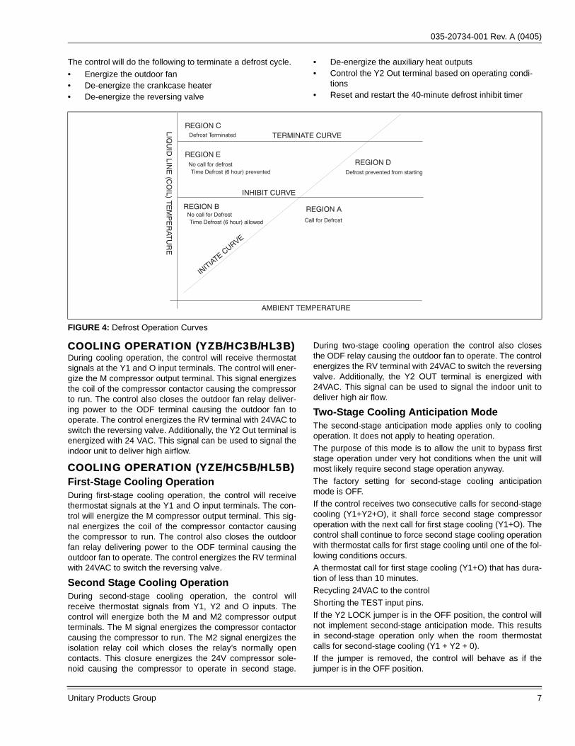
The control will initiate a defrost cycle when the liquid linetemperature is below the initiate point for the measured ambi-ent temperature (See Figure 4) continuously for 4-1/2 min-utes. This delay eliminates unnecessary defrost cyclescaused by refrigeration surges such as those that occur atthe start of a heating cycle.The control will initiate a defrost cycle every 6 hours (accu-mulated compressor run time) to recirculate refrigerant lubri-cants. This forced defrost timer will be reset and restartedfollowing the completion or termination of a defrost cycle.The control will also initiate a defrost cycle when the TESTterminals are shorted. This feature allows an installer or ser-vice technician to start a defrost cycle immediately asrequired. When the TEST terminals are shorted for more thansix seconds with a Y1 input energized and the high-pressureswitch closed, the ASCD will be bypassed and the compres-sor will be energized. If an O signal is present, the control willnot initiate a defrost cycle. If the defrost cycle is initiatedusing the TEST terminals, the control will bypass the normalauxiliary heat timings and will energize the W1 Out and W2Out terminals immediately when it begins the defrost cycle. When the TEST inputs are used to force a defrost cycle, thecontrol will ignore the state of the liquid line temperature andoutdoor ambient temperature inputs. The coil does not haveto be cold and the outdoor temperature does not have to bewithin a certain range for the heat pump to be forced into adefrost cycle. After the TEST input jumper is removed, thedefrost mode will be terminated as normal. The defrost cyclelength timer will not be started until the TEST input isremoved. If the TEST terminals remain shorted, the controlwill keep the unit in defrost mode.
Defrost InhibitionThe control will not initiate a defrost cycle if the liquid linetemperature is above 40F unless the defrost cycle is forcedusing the TEST input.The control will not initiate a defrost cycle when the outdoorambient temperature is below –25F or above 55F unless thedefrost cycle is forced using the TEST input. The control will also prevent a defrost cycle from being initi-ated too soon after the initiation of the previous defrost cycle.When power is applied to the control and after the completionor termination of each defrost cycle, the control will start a 40-minute timer. When this timer expires, the control will allowanother defrost cycle when needed. The timer is based onaccumulated compressor run time.
Defrost TerminationThe control will terminate the defrost cycle immediately afterthe liquid line temperature reaches 80F or after eight minutesof defrost operation.The control will also terminate a defrost cycle that has beenforced using the TEST input when the O input is energized.The control will not terminate a normal defrost cycle when itreceives an O input.
035-20734-001 Rev. A (0405)
Unitary Products Group 7
The control will do the following to terminate a defrost cycle.• Energize the outdoor fan• De-energize the crankcase heater• De-energize the reversing valve
• De-energize the auxiliary heat outputs• Control the Y2 Out terminal based on operating condi-
tions• Reset and restart the 40-minute defrost inhibit timer
COOLING OPERATION (YZB/HC3B/HL3B)During cooling operation, the control will receive thermostatsignals at the Y1 and O input terminals. The control will ener-gize the M compressor output terminal. This signal energizesthe coil of the compressor contactor causing the compressorto run. The control also closes the outdoor fan relay deliver-ing power to the ODF terminal causing the outdoor fan tooperate. The control energizes the RV terminal with 24VAC toswitch the reversing valve. Additionally, the Y2 Out terminal isenergized with 24 VAC. This signal can be used to signal theindoor unit to deliver high airflow.
COOLING OPERATION (YZE/HC5B/HL5B)First-Stage Cooling OperationDuring first-stage cooling operation, the control will receivethermostat signals at the Y1 and O input terminals. The con-trol will energize the M compressor output terminal. This sig-nal energizes the coil of the compressor contactor causingthe compressor to run. The control also closes the outdoorfan relay delivering power to the ODF terminal causing theoutdoor fan to operate. The control energizes the RV terminalwith 24VAC to switch the reversing valve.
Second Stage Cooling OperationDuring second-stage cooling operation, the control willreceive thermostat signals from Y1, Y2 and O inputs. Thecontrol will energize both the M and M2 compressor outputterminals. The M signal energizes the compressor contactorcausing the compressor to run. The M2 signal energizes theisolation relay coil which closes the relay’s normally opencontacts. This closure energizes the 24V compressor sole-noid causing the compressor to operate in second stage.
During two-stage cooling operation the control also closesthe ODF relay causing the outdoor fan to operate. The controlenergizes the RV terminal with 24VAC to switch the reversingvalve. Additionally, the Y2 OUT terminal is energized with24VAC. This signal can be used to signal the indoor unit todeliver high air flow.
Two-Stage Cooling Anticipation ModeThe second-stage anticipation mode applies only to coolingoperation. It does not apply to heating operation.The purpose of this mode is to allow the unit to bypass firststage operation under very hot conditions when the unit willmost likely require second stage operation anyway.The factory setting for second-stage cooling anticipationmode is OFF.If the control receives two consecutive calls for second-stagecooling (Y1+Y2+O), it shall force second stage compressoroperation with the next call for first stage cooling (Y1+O). Thecontrol shall continue to force second stage cooling operationwith thermostat calls for first stage cooling until one of the fol-lowing conditions occurs.A thermostat call for first stage cooling (Y1+O) that has dura-tion of less than 10 minutes.Recycling 24VAC to the controlShorting the TEST input pins.If the Y2 LOCK jumper is in the OFF position, the control willnot implement second-stage anticipation mode. This resultsin second-stage operation only when the room thermostatcalls for second-stage cooling (Y1 + Y2 + 0).If the jumper is removed, the control will behave as if thejumper is in the OFF position.
FIGURE 4: Defrost Operation Curves
REGION CTERMINATE CURVE
INHIBIT CURVE
INITIATE C
URVE
REGION AREGION B
REGION DREGION E
AMBIENT TEMPERATURE
LIQU
ID LIN
E (C
OIL) T
EM
PE
RAT
UR
E
Defrost prevented from startingNo call for defrostTime Defrost (6 hour) prevented
No call for DefrostTime Defrost (6 hour) allowed Call for Defrost
Defrost Terminated
035-20734-001 Rev. A (0405)
8 Unitary Products Group
HEATING OPERATION (YZB/HC3B/HL3B)During normal heating mode, the control will receive a ther-mostat signal at the Y1 input terminal. The control will ener-gize the M compressor output terminal. This signal energizesthe coil of the compressor contactor causing the compressorto run. The control also closes the outdoor fan relay deliver-ing power to the ODF terminal causing the outdoor fan tooperate. The reversing valve is not energized in heatingmode. If the Y2 terminal of the control is energized when theY1 terminal is not energized, the control will display and storea fault code and will not energize the compressor.
HEATING OPERATION (YZE/HC5B/HL5B)First-Stage Heating OperationDuring first-stage heating operation, the control will receive athermostat signal at the Y1 input terminal. The control willenergize the M compressor output terminal. This signal ener-gizes the coil of the compressor contactor causing the com-pressor to run. The control also closes the outdoor fan relaydelivering power to the ODF terminal causing the outdoor fanto operate. The reversing valve is not energized in heatingmode.
Second-Stage Heating OperationDuring second-stage heating operation, the control willreceive a thermostat signal at the Y1 and Y2 input terminals.The control will energize the M and M2 compressor outputterminals. The M signal energizes the coil of the compressorcontactor causing the compressor to run. The M2 signal ener-gizes the isolation relay coil which closes the relay’s normallyopen contacts. This closure energizes the 24V compressorsolenoid causing the compressor to operate in second-stage.The control also closes the ODF relay causing the outdoorfan to operate. The Y2 OUT terminal may or may not be ener-gized depending on the HP mode of operation (conventionalvs. hot heat pump).
Conventional Heat Pump Mode (All Models)The factory setting of the HOT HEAT PUMP jumper on thecontrol is the OFF position. In this configuration the heatpump operates in conventional heat pump mode. If thejumper is not in place, the control will act as if the jumper is inthe OFF position.If the HOT HEAT PUMP jumper is in the OFF position, thecontrol will energize the Y2 Out terminal whenever the com-pressor is running.The location of the hot heat pump jumper is shown in Figures1 & 3.
Hot Heat Pump Mode (All Models)The control will operate in Hot Heat Pump Mode only if theHOT HEAT PUMP jumper on the control is placed in the ONposition. The Y2 Out signal must also be connected to theindoor unit.The SWITCH POINT jumper on the control has no effect onthe operation of the heat pump.The control implements the Hot Heat Pump Mode by control-ling the indoor airflow level during heating operation only.
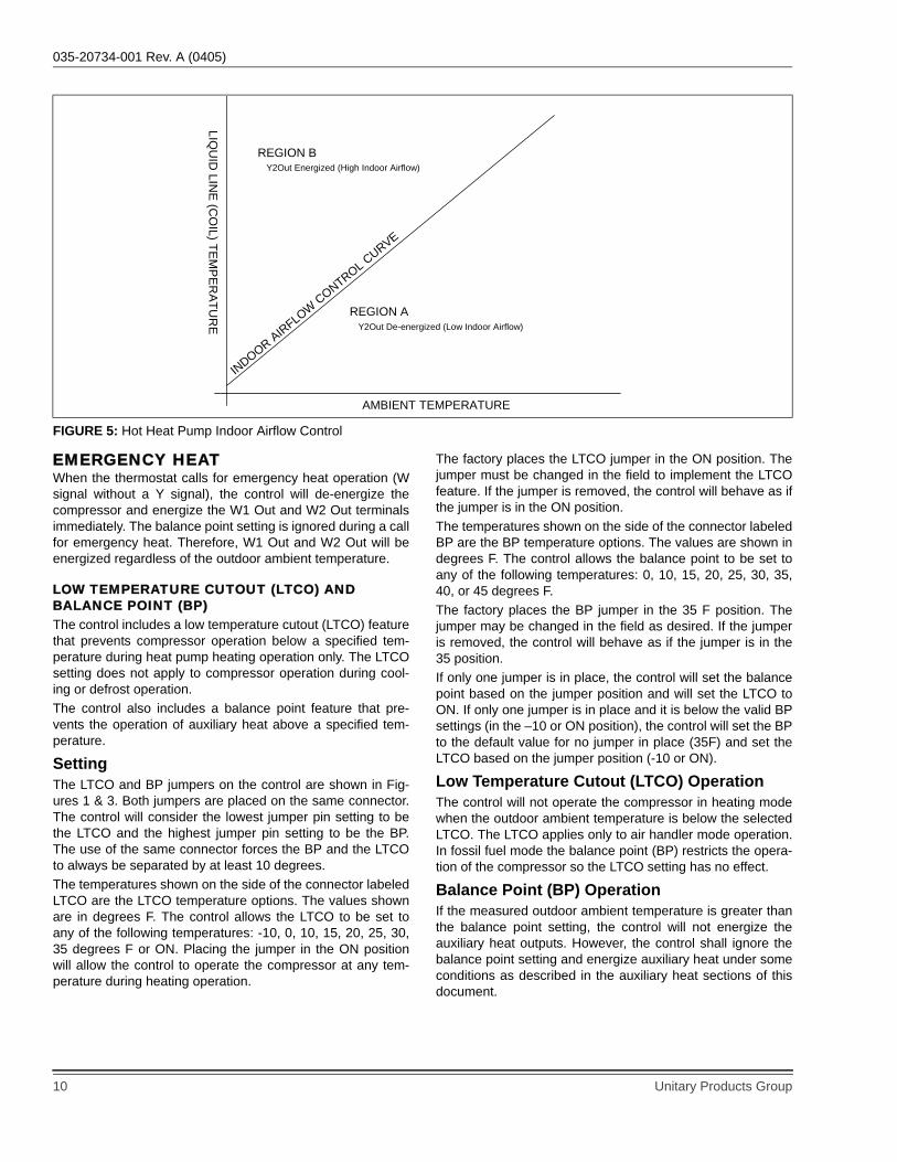
Cooling operation is not affected. By reducing the indoor air-flow level, the heat pump system will operate with increasedindoor discharge air temperatures. The control changes theindoor airflow level using the Y2 Out signal. This terminal isconnected to the high speed cooling input of a variable speedindoor unit. When the heat pump control energizes the Y2Out terminal, the indoor blower runs at high speed deliveringhigh airflow. When the control de-energizes the Y2 Out termi-nal, the indoor blower runs at a lower speed delivering lowerairflow.If the HOT HP jumper is in the ON position and the controlreceives a call for heating (Y1), the control will energize thecompressor and measure the outdoor ambient temperature. If the outdoor ambient temperature is equal to or greater than50F, the control will energize Y2 Out and keep it energizeduntil the thermostat is satisfied (Y1 signal removed). Thehigher airflow is required to keep the operating pressures lowwhen the outdoor ambient temperature is 50F or greater. If the outdoor ambient temperature is less than 50F, the con-trol will start a ten-minute timer and keep Y2 Out de-ener-gized. Therefore, the compressor will be operating and theindoor unit will be operating with reduced airflow. If the HOTHP jumper is in the ON position and if the outdoor ambi-ent temperature is less than 50F, the indoor airflow at thebeginning of a heating cycle will always be low.When the ten-minute timer expires, the control will measurethe liquid line temperature and determine whether to energizeY2 Out and increase the indoor airflow or keep Y2 Out de-energized and maintain reduced indoor airflow. The controlcompares the measured liquid line temperature to a pre-pro-grammed indoor airflow curve. It continues to keep Y2 Outde-energized until the liquid line temperature exceeds thecurve for the given outdoor ambient temperature continuallyfor 30 seconds. If the liquid line temperature drops below thecurve, the control will reset the 30-second timer and restart itwhen the liquid line temperature again exceeds the curve.When the liquid line temperature exceeds the indoor airflowcontrol curve continually for 30 seconds, the control will ener-gize Y2 Out, i.e. cause high indoor airflow, until the thermo-stat demand is satisfied and the thermostat signal inputs areremoved. Figure 5 describes the required behavior.Once the control energizes Y2 Out to create high airflow, itwill keep Y2 Out energized until the thermostat is satisfiedand the call for heating is removed. It will do this regardless ofa change in outdoor ambient or liquid line temperature.Therefore, if the control energizes Y2 Out because the out-door ambient temperature is greater than or equal to 50F orbecause the liquid line temperature exceeds the curve for thegiven outdoor ambient temperature (point within region B), itwill keep Y2 Out energized until the thermostat is satisfiedeven if the liquid line or outdoor ambient temperature fallsbelow the curve (point within region A).The control of Y2 Out to generate high indoor airflow asrequired will prevent the heat pump system pressures andtemperatures from becoming too great when the compressoris running at full capacity with low indoor airflow.
035-20734-001 Rev. A (0405)
Unitary Products Group 9
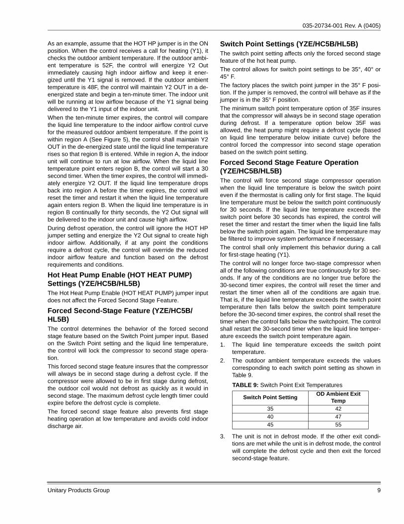
As an example, assume that the HOT HP jumper is in the ONposition. When the control receives a call for heating (Y1), itchecks the outdoor ambient temperature. If the outdoor ambi-ent temperature is 52F, the control will energize Y2 Outimmediately causing high indoor airflow and keep it ener-gized until the Y1 signal is removed. If the outdoor ambienttemperature is 48F, the control will maintain Y2 OUT in a de-energized state and begin a ten-minute timer. The indoor unitwill be running at low airflow because of the Y1 signal beingdelivered to the Y1 input of the indoor unit. When the ten-minute timer expires, the control will comparethe liquid line temperature to the indoor airflow control curvefor the measured outdoor ambient temperature. If the point iswithin region A (See Figure 5), the control shall maintain Y2OUT in the de-energized state until the liquid line temperaturerises so that region B is entered. While in region A, the indoorunit will continue to run at low airflow. When the liquid linetemperature point enters region B, the control will start a 30second timer. When the timer expires, the control will immedi-ately energize Y2 OUT. If the liquid line temperature dropsback into region A before the timer expires, the control willreset the timer and restart it when the liquid line temperatureagain enters region B. When the liquid line temperature is inregion B continually for thirty seconds, the Y2 Out signal willbe delivered to the indoor unit and cause high airflow.During defrost operation, the control will ignore the HOT HPjumper setting and energize the Y2 Out signal to create highindoor airflow. Additionally, if at any point the conditionsrequire a defrost cycle, the control will override the reducedindoor airflow feature and function based on the defrostrequirements and conditions.
Hot Heat Pump Enable (HOT HEAT PUMP) Settings (YZE/HC5B/HL5B)The Hot Heat Pump Enable (HOT HEAT PUMP) jumper inputdoes not affect the Forced Second Stage Feature.
Forced Second-Stage Feature (YZE/HC5B/HL5B)The control determines the behavior of the forced secondstage feature based on the Switch Point jumper input. Basedon the Switch Point setting and the liquid line temperature,the control will lock the compressor to second stage opera-tion.This forced second stage feature insures that the compressorwill always be in second stage during a defrost cycle. If thecompressor were allowed to be in first stage during defrost,the outdoor coil would not defrost as quickly as it would insecond stage. The maximum defrost cycle length timer couldexpire before the defrost cycle is complete.The forced second stage feature also prevents first stageheating operation at low temperature and avoids cold indoordischarge air.
Switch Point Settings (YZE/HC5B/HL5B)The switch point setting affects only the forced second stagefeature of the hot heat pump.The control allows for switch point settings to be 35°, 40° or45° F.The factory places the switch point jumper in the 35° F posi-tion. If the jumper is removed, the control will behave as if thejumper is in the 35° F position.The minimum switch point temperature option of 35F insuresthat the compressor will always be in second stage operationduring defrost. If a temperature option below 35F wasallowed, the heat pump might require a defrost cycle (basedon liquid line temperature below initiate curve) before thecontrol forced the compressor into second stage operationbased on the switch point setting.
Forced Second Stage Feature Operation (YZE/HC5B/HL5B)The control will force second stage compressor operationwhen the liquid line temperature is below the switch pointeven if the thermostat is calling only for first stage. The liquidline temperature must be below the switch point continuouslyfor 30 seconds. If the liquid line temperature exceeds theswitch point before 30 seconds has expired, the control willreset the timer and restart the timer when the liquid line fallsbelow the switch point again. The liquid line temperature maybe filtered to improve system performance if necessary.The control shall only implement this behavior during a callfor first-stage heating (Y1).The control will no longer force two-stage compressor whenall of the following conditions are true continuously for 30 sec-onds. If any of the conditions are no longer true before the30-second timer expires, the control will reset the timer andrestart the timer when all of the conditions are again true.That is, if the liquid line temperature exceeds the switch pointtemperature then falls below the switch point temperaturebefore the 30-second timer expires, the control shall reset thetimer when the control falls below the switchpoint. The controlshall restart the 30-second timer when the liquid line temper-ature exceeds the switch point temperature again. 1. The liquid line temperature exceeds the switch point
temperature. 2. The outdoor ambient temperature exceeds the values
corresponding to each switch point setting as shown inTable 9.
3. The unit is not in defrost mode. If the other exit condi-tions are met while the unit is in defrost mode, the controlwill complete the defrost cycle and then exit the forcedsecond-stage feature.
TABLE 9: Switch Point Exit Temperatures
Switch Point Setting OD Ambient Exit Temp
35 4240 4745 55
035-20734-001 Rev. A (0405)
10 Unitary Products Group
EMERGENCY HEATWhen the thermostat calls for emergency heat operation (Wsignal without a Y signal), the control will de-energize thecompressor and energize the W1 Out and W2 Out terminalsimmediately. The balance point setting is ignored during a callfor emergency heat. Therefore, W1 Out and W2 Out will beenergized regardless of the outdoor ambient temperature.
LOW TEMPERATURE CUTOUT (LTCO) AND BALANCE POINT (BP)The control includes a low temperature cutout (LTCO) featurethat prevents compressor operation below a specified tem-perature during heat pump heating operation only. The LTCOsetting does not apply to compressor operation during cool-ing or defrost operation.The control also includes a balance point feature that pre-vents the operation of auxiliary heat above a specified tem-perature.
SettingThe LTCO and BP jumpers on the control are shown in Fig-ures 1 & 3. Both jumpers are placed on the same connector.The control will consider the lowest jumper pin setting to bethe LTCO and the highest jumper pin setting to be the BP.The use of the same connector forces the BP and the LTCOto always be separated by at least 10 degrees.The temperatures shown on the side of the connector labeledLTCO are the LTCO temperature options. The values shownare in degrees F. The control allows the LTCO to be set toany of the following temperatures: -10, 0, 10, 15, 20, 25, 30,35 degrees F or ON. Placing the jumper in the ON positionwill allow the control to operate the compressor at any tem-perature during heating operation.
The factory places the LTCO jumper in the ON position. Thejumper must be changed in the field to implement the LTCOfeature. If the jumper is removed, the control will behave as ifthe jumper is in the ON position.The temperatures shown on the side of the connector labeledBP are the BP temperature options. The values are shown indegrees F. The control allows the balance point to be set toany of the following temperatures: 0, 10, 15, 20, 25, 30, 35,40, or 45 degrees F.The factory places the BP jumper in the 35 F position. Thejumper may be changed in the field as desired. If the jumperis removed, the control will behave as if the jumper is in the35 position.If only one jumper is in place, the control will set the balancepoint based on the jumper position and will set the LTCO toON. If only one jumper is in place and it is below the valid BPsettings (in the –10 or ON position), the control will set the BPto the default value for no jumper in place (35F) and set theLTCO based on the jumper position (-10 or ON).
Low Temperature Cutout (LTCO) OperationThe control will not operate the compressor in heating modewhen the outdoor ambient temperature is below the selectedLTCO. The LTCO applies only to air handler mode operation.In fossil fuel mode the balance point (BP) restricts the opera-tion of the compressor so the LTCO setting has no effect.
Balance Point (BP) OperationIf the measured outdoor ambient temperature is greater thanthe balance point setting, the control will not energize theauxiliary heat outputs. However, the control shall ignore thebalance point setting and energize auxiliary heat under someconditions as described in the auxiliary heat sections of thisdocument.
FIGURE 5: Hot Heat Pump Indoor Airflow Control
INDOOR AIRFLOW CONTROL CURVE
REGION A
REGION B
AMBIENT TEMPERATURE
LIQU
ID LIN
E (CO
IL) TEM
PER
ATUR
E
Y2Out Energized (High Indoor Airflow)
Y2Out De-energized (Low Indoor Airflow)
035-20734-001 Rev. A (0405)
Unitary Products Group 11
FOSSIL FUEL JUMPER (FFUEL)SettingThe control includes a FFUEL jumper to specify whether thecontrol is installed with a fossil fuel furnace or an air handler(electric heat). This jumper is shown in Figures 1 & 3. Thefactory places the FFUEL jumper in the OFF position which isthe correct position for an air handler installation. The jumpermust be changed to the ON position in the field if the heatpump is installed with a fossil fuel furnace. If the jumper isremoved, the control will behave as if the jumper is in theOFF position.IMPORTANT: If the heat pump is installed with a fossil fuelfurnace, the FFUEL jumper must be placed in the ON posi-tion during installation for proper system operation.
OperationThe control operates the auxiliary heat outputs, W1 Out andW2 Out, based on the position of the FFUEL jumper. If theFFUEL jumper is in the ON position, the control will functionin fossil fuel mode. If the jumper is in the OFF position, thecontrol will function in air handler mode. The FFUEL jumperhas no effect on cooling operation.
AUXILIARY HEAT - AIR HANDLER MODEThe heat pump control energizes the auxiliary electric heat inair handler mode using the W1 Out and W2 Out signals. Thecontrol receives the room thermostat call for auxiliary heat atthe W input terminal.
Standard Operation (YZB/HC3B/HL3B)If the outdoor ambient temperature is less than ten degrees Fbelow the balance point setting and a W input is received witha Y1 input, the control will energize the M compressor con-tactor output based on the Y1 input and will energize the W1Out immediately when the W input is received. When the Winput is received, the control will start a fifteen-minute timer. Ifthe call for Y1 + W is still present after the fifteen-minute timerexpires, the control will then energize W2 Out along with W1Out. If the W input is removed but the Y1 signal remains, thecontrol will de-energize W1 Out and W2 Out (if energized)and reset and restart the timer. If the W input is receivedagain without a loss of the Y1, the same functionality will berepeated.If the outdoor ambient temperature is ten degrees F or morebelow the balance point setting and a W input is received witha Y1 input, the control will energize W1 Out and W2 Outimmediately.
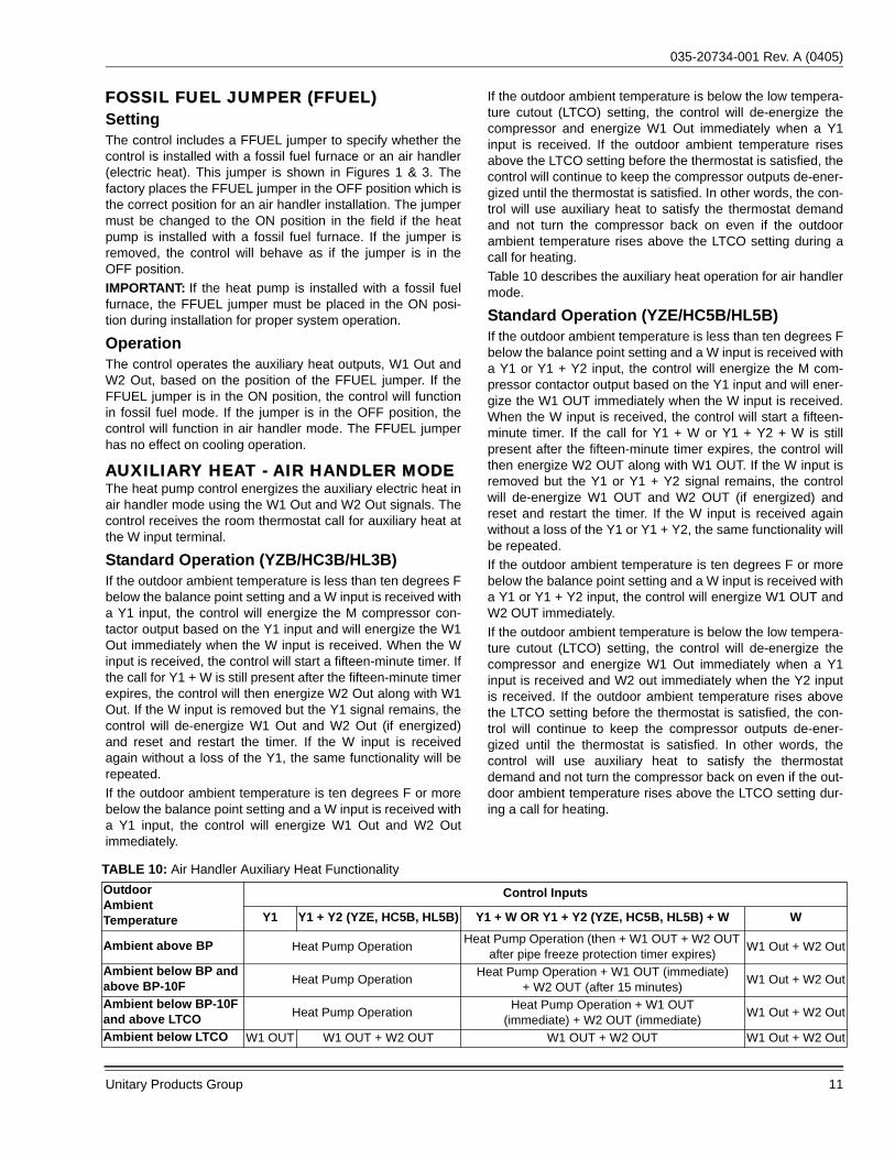
If the outdoor ambient temperature is below the low tempera-ture cutout (LTCO) setting, the control will de-energize thecompressor and energize W1 Out immediately when a Y1input is received. If the outdoor ambient temperature risesabove the LTCO setting before the thermostat is satisfied, thecontrol will continue to keep the compressor outputs de-ener-gized until the thermostat is satisfied. In other words, the con-trol will use auxiliary heat to satisfy the thermostat demandand not turn the compressor back on even if the outdoorambient temperature rises above the LTCO setting during acall for heating.Table 10 describes the auxiliary heat operation for air handlermode.
Standard Operation (YZE/HC5B/HL5B)If the outdoor ambient temperature is less than ten degrees Fbelow the balance point setting and a W input is received witha Y1 or Y1 + Y2 input, the control will energize the M com-pressor contactor output based on the Y1 input and will ener-gize the W1 OUT immediately when the W input is received.When the W input is received, the control will start a fifteen-minute timer. If the call for Y1 + W or Y1 + Y2 + W is stillpresent after the fifteen-minute timer expires, the control willthen energize W2 OUT along with W1 OUT. If the W input isremoved but the Y1 or Y1 + Y2 signal remains, the controlwill de-energize W1 OUT and W2 OUT (if energized) andreset and restart the timer. If the W input is received againwithout a loss of the Y1 or Y1 + Y2, the same functionality willbe repeated.If the outdoor ambient temperature is ten degrees F or morebelow the balance point setting and a W input is received witha Y1 or Y1 + Y2 input, the control will energize W1 OUT andW2 OUT immediately.If the outdoor ambient temperature is below the low tempera-ture cutout (LTCO) setting, the control will de-energize thecompressor and energize W1 Out immediately when a Y1input is received and W2 out immediately when the Y2 inputis received. If the outdoor ambient temperature rises abovethe LTCO setting before the thermostat is satisfied, the con-trol will continue to keep the compressor outputs de-ener-gized until the thermostat is satisfied. In other words, thecontrol will use auxiliary heat to satisfy the thermostatdemand and not turn the compressor back on even if the out-door ambient temperature rises above the LTCO setting dur-ing a call for heating.
TABLE 10: Air Handler Auxiliary Heat FunctionalityOutdoor Ambient Temperature
Control Inputs
Y1 Y1 + Y2 (YZE, HC5B, HL5B) Y1 + W OR Y1 + Y2 (YZE, HC5B, HL5B) + W W
Ambient above BP Heat Pump Operation Heat Pump Operation (then + W1 OUT + W2 OUT after pipe freeze protection timer expires) W1 Out + W2 Out
Ambient below BP and above BP-10F Heat Pump Operation Heat Pump Operation + W1 OUT (immediate)
+ W2 OUT (after 15 minutes) W1 Out + W2 Out
Ambient below BP-10F and above LTCO Heat Pump Operation Heat Pump Operation + W1 OUT
(immediate) + W2 OUT (immediate) W1 Out + W2 Out
Ambient below LTCO W1 OUT W1 OUT + W2 OUT W1 OUT + W2 OUT W1 Out + W2 Out
035-20734-001 Rev. A (0405)
12 Unitary Products Group
Auxiliary Heat Defrost Operation – Air Handler ModeThe control will energize W1 Out and W2 Out 45 secondsprior to and during defrost operation. If a call for heating (Y1or Y1 + Y2 for 2-stage models) is still present after the defrostcycle has terminated, the control will continue to energize W1Out and W2 Out for 180 seconds after the defrost cycle hasbeen terminated. The control will begin normal heat pumpheating mode operation upon termination of the defrost cycle.
Pipe Freeze Protection Timer – Air Handler Mode OperationThe control starts a four hour timer when a call for compres-sor operation and auxiliary heat (Y1 + W or Y1 + Y2 + W for2-stage models) is received. If the call for compressor opera-tion and auxiliary heat is still present after the timer expires,the control will energize W1 Out and W2 Out in addition to thecompressor output regardless of the balance point setting.If the call for auxiliary heat (W) is removed but the call forcompressor operation (Y1 or Y1 + Y2 for 2-stage models)remains, the control will de-energize auxiliary heat (W1 Outand W2 Out) and reset and restart the timer. If the timerexpires again, the same functionality will be repeated indefi-nitely. The purpose of this feature is to prevent the pipes in ahome from freezing if the balance point is set too low and theheat pump cannot heat the home using compressor opera-tion only. This will be a benefit if a home is not occupied and acompressor problem occurs. The control shall also store anddisplay a fault flash code when the pipe freeze timer hasexpired.
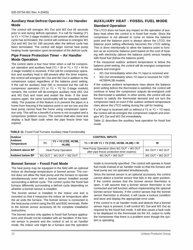
AUXILIARY HEAT - FOSSIL FUEL MODEStandard OperationThe LTCO does not have any impact on the operation of aux-iliary heat when the control is in fossil fuel mode. Since thecompressor is not allowed to come on below the balancepoint and the balance point is always above the LTCO, thebalance point setting effectively becomes the LTCO setting.This is done intentionally to allow the balance point to func-tion as an economic balance point based on the cost of heat-ing with electricity (above the balance point) versus heatingwith fossil fuel (below the balance point).If the measured outdoor ambient temperature is below thebalance point setting, the control will de-energize compressoroutputs and energize: • W1 Out immediately when the Y1 input is received and• W2 Out immediately when Y2 input is received for YZE/
HC5B/HL5B models. If the outdoor ambient temperature rises above the balancepoint setting before the thermostat is satisfied, the control willcontinue to keep the compressor outputs de-energized untilthe thermostat is satisfied. In other words, the control will usefurnace to satisfy the thermostat demand and not turn thecompressor back on even if the outdoor ambient temperaturerises above the LTCO setting during the call for heating.If a W input is received with or without a Y1 or Y1 + Y2 input,the control will de-energize the compressor outputs and ener-gize W1 Out and W2 Out immediately. Table 11 describes the auxiliary heat operation for fossil fuelmode.
Bonnet Sensor – Fossil Fuel ModeThe heat pump may be equipped in the field with an optionalindoor air discharge temperature or bonnet sensor. The con-trol does not allow the heat pump and the furnace to operatesimultaneously even with a bonnet sensor installed exceptsurrounding a defrost cycle. The control cycles the fossil fuelfurnace differently surrounding a defrost cycle depending onwhether a bonnet sensor is installed.The bonnet sensor is installed in the indoor unit and ismounted so that it measures the indoor air temperature afterthe air exits the furnace. The bonnet sensor is connected tothe heat pump control using the BS and BSG terminals. Referto the bonnet sensor accessory kit for complete installationinstructions.The bonnet sensor only applies to fossil fuel furnace applica-tions and should not be installed with air handlers. If the bon-net sensor is present and the control is set to air handlermode, the indoor unit might be a furnace and the operation
mode is incorrectly specified. The control will operate in fossilfuel mode instead of air handler mode so that the furnace andheat pump are not operated simultaneously.Since the bonnet sensor is an optional accessory, the controlcannot detect a bonnet sensor that fails in the open position.If the control senses that the bonnet sensor thermistor isopen, it will assume that a bonnet sensor thermistor is notconnected and will function without implementing the optionalbonnet sensor features. If the control senses that the bonnetsensor thermistor is shorted, it will cause a lockout conditionand store and display the appropriate error code.If the control is in air handler mode and detects that a bonnetsensor input is present, it will control W1 Out and W2 Out asrequired by the fossil fuel mode. It will also cause a fault codeto be displayed on the thermostat via the X/L output to notifythe homeowner that there is a problem even though the sys-tem is operating.
TABLE 11: Fossil Fuel Furnace Auxiliary Heat Functionality
Outdoor Ambient Temperature
CONTROL INPUTS
Y1 Y1 + Y2 (YZE, HC5B, HL5B) Y1 + W OR Y1 + Y2 (YZE, HC5B, HL5B) + W W
Ambient above BP Heat Pump Operation Heat Pump Operation (then W1 OUT + W2 OUTafter pipe freeze protection timer expires) W1 OUT + W2 OUT
Ambient below BP W1 OUT W1 OUT + W2 OUT W1 OUT + W2 OUT W1 OUT + W2 OUT
035-20734-001 Rev. A (0405)
Unitary Products Group 13
Auxiliary Heat Defrost Operation – Fossil Fuel Mode with Bonnet SensorWith a bonnet sensor present the control will energize W1Out and W2 Out 45 seconds prior to the initiation of thedefrost cycle.During defrost operation, if the bonnet sensor input reaches109F, the control will de-energize W1Out and W2Out. Thecontrol will re-energize W1Out and W2Out when the bonnetsensor input drops below 90F again and the defrost cycle isstill in process.If a call for heating (Y1) is still present after the defrost cyclehas terminated, the control will continue to energize W1 Outand W2 Out after the defrost cycle has been terminated untilthe bonnet sensor reaches 109F. When the bonnet sensorreaches 109F after the defrost cycle has terminated, the con-trol will de-energize W1 Out and W2 Out and will not re-ener-gize them during this call for heat. That is, once the defrostcycle has terminated, the control will not cycle W1 Out andW2 Out with the bonnet sensor.The control will begin normal heat pump heating mode opera-tion upon termination of the defrost cycle.
Auxiliary Heat Defrost Operation – Fossil Fuel Mode without Bonnet SensorIf the control is in fossil fuel mode and senses that no bonnetsensor is present, it will energize W1 Out and W2 Out imme-diately when the defrost cycle is initiated. If a call for heating(Y1) is still present after the defrost cycle has terminated, thecontrol will de-energize W1 Out and W2 Out immediately andreturn to normal heat pump mode operation.In this mode the control will energize the fossil fuel furnaceonly during defrost and not provide any comfort enhance-ments during the transition. The heat pump and furnace willnot operate at the same time if the bonnet sensor is not inplace.
Pipe Freeze Protection Timer – Fossil Fuel Mode OperationThe control starts a four hour timer when a call for compres-sor operation and auxiliary heat (Y1 + W) is received. If theoutdoor temperature is above the balance point, the controlwill energize the compressor instead of the auxiliary heat out-puts. If the call for compressor operation and auxiliary heat isstill present after the timer expires, the control will energizeW1 Out and W2 Out and de-energize the compressor regard-less of the balance point setting. The control will keep theW1 Out and W2 Out signals energized until the Y1 signal isremoved. That is, the control will lock into auxiliary heat fur-nace operation until the room thermostat is satisfied. The pur-pose of this feature is to prevent the pipes in a home fromfreezing if the balance point is set too low and the heat pumpcannot heat the home using compressor operation only. Thiswill be a benefit if a home is not occupied and a compressorproblem occurs. The control will also store and display a faultflash code when the pipe freeze timer has expired.
Y2 LOCK The control includes a Y2 LOCK feature which allows the unitto anticipate the need for second-stage cooling during high-load conditions. Refer to the “Second-Stage Cooling Anticipa-tion Mode” section of this document for detailed information.The Y2 Lock jumper on the control is shown in figures 1 & 3.The factory places the Y2 Lock jumper in the ON position. Ifthe jumper is removed, the control will behave as if thejumper is in the ON position.
SWITCH POINTThe control includes a switch point feature which determinesthe liquid temperatures at which the compressor will beforced to operate in second-stage. Refer to the “Switch PointOperation” section of this document for detailed information.
SettingThe switch point jumper on the control is shown in Figure 1 &3. The control allows for switch point settings to be 35, 40 or45. The valves shown are in degrees F.The factory places the switch point jumper in the 35°F posi-tion. If the jumper is removed, the control will behave as if thejumper is in the 35°F position. The switch point feature isused exclusively for the HP heating operation mode. Coolingoperation is not effected by switch point setting.
HIGH-PRESSURE SWITCH FAULTThe heat pump is equipped with a high-pressure switch thatis connected to the control at the HPS terminals. If the high-pressure switch opens for more than 40 milliseconds, thecontrol will de-energize the compressor and store and displaythe appropriate fault code. If the pressure switch closes and athermostat call for compressor operation is present, the con-trol will apply the five-minute anti-short cycle delay timer andstart the compressor when the timer expires.When the compressor is started following a high-pressureswitch fault, the control will start a six-hour timer based onaccumulated compressor run time. If the control sensesanother opening of the high-pressure switch before the timerexpires, it will cause a soft lockout condition. The secondopening of the high-pressure switch must be greater than 160milliseconds for the lockout to occur. If the second opening isbetween 40 and 160 milliseconds, the control will de-energizethe compressor but not cause a soft lockout condition. If thecontrol does not sense a second high-pressure switch open-ing before the six-hour timer expires, the timer and counterwill be reset.
035-20734-001 Rev. A (0405)
14 Unitary Products Group
LOW-PRESSURE SWITCHThe heat pump is equipped with a low-pressure switch whichis connected to the control at the LPS terminals. If the low-pressure switch opens for more than five seconds, the controlwill cause a soft lockout condition and display the appropriatefault codes. However, the control will ignore the low pressureswitch input and not cause a soft lockout condition if it opensduring the following conditions.• Defrost operation• First two minutes of compressor operation• Two minutes following the completion of a defrost cycle• TEST input shorted with Y1 input energized
DISCHARGE LINE TEMPERATURE SEN-SOR (OPTIONAL)The heat pump may be equipped with an optional dischargeline temperature sensor. If a discharge sensor is present, thecontrol will provide the following features.
High Discharge Line TemperatureIf the control senses a discharge line temperature reading of263F for 30 seconds continually, it will cause a soft lockoutcondition. If the discharge line temperature drops below 263Fduring the 30-second timer, the control will reset the 30-sec-ond timer and restart the timer if the discharge line tempera-ture again exceeds 263F.
Low Discharge Line TemperatureThe control will begin a sixty-minute timer when either of thefollowing conditions are met. • The discharge line temperature has not reached 90F
after eight minutes of accumulated compressor run time.• The discharge temperature has not reached 90F after fif-
teen minutes of accumulated compressor run time fol-lowing the exit of a defrost cycle.
If the discharge line temperature has not reached 90F afterthe sixty-minute timer has expired, the control will cause asoft lockout condition. The control will reset the sixty-minutetimer upon expiration and when the compressor starts. Thetimer is reset when the compressor starts and is onlyrestarted if one of the two conditions shown above are met.The low discharge temperature fault indicates that the out-door coil is too cold during heating operation. The lockout isintended to prevent refrigerant flooding back to the compres-sor.IMPORTANT: The discharge sensor must be well insulatedand installed properly to prevent nuisance lockouts fromoccurring.
035-20734-001 Rev. A (0405)
Unitary Products Group 15
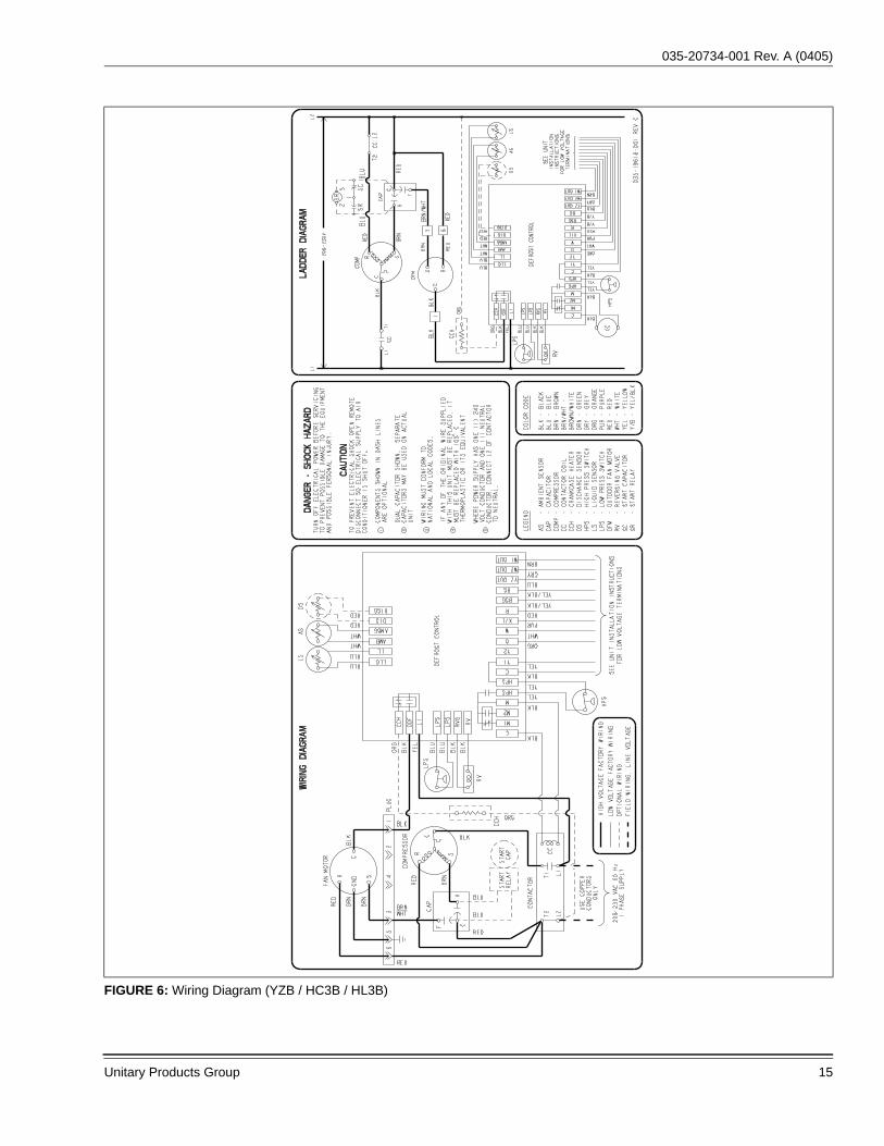
FIGURE 6: Wiring Diagram (YZB / HC3B / HL3B)
035-20734-001 Rev. A (0405)
16 Unitary Products Group
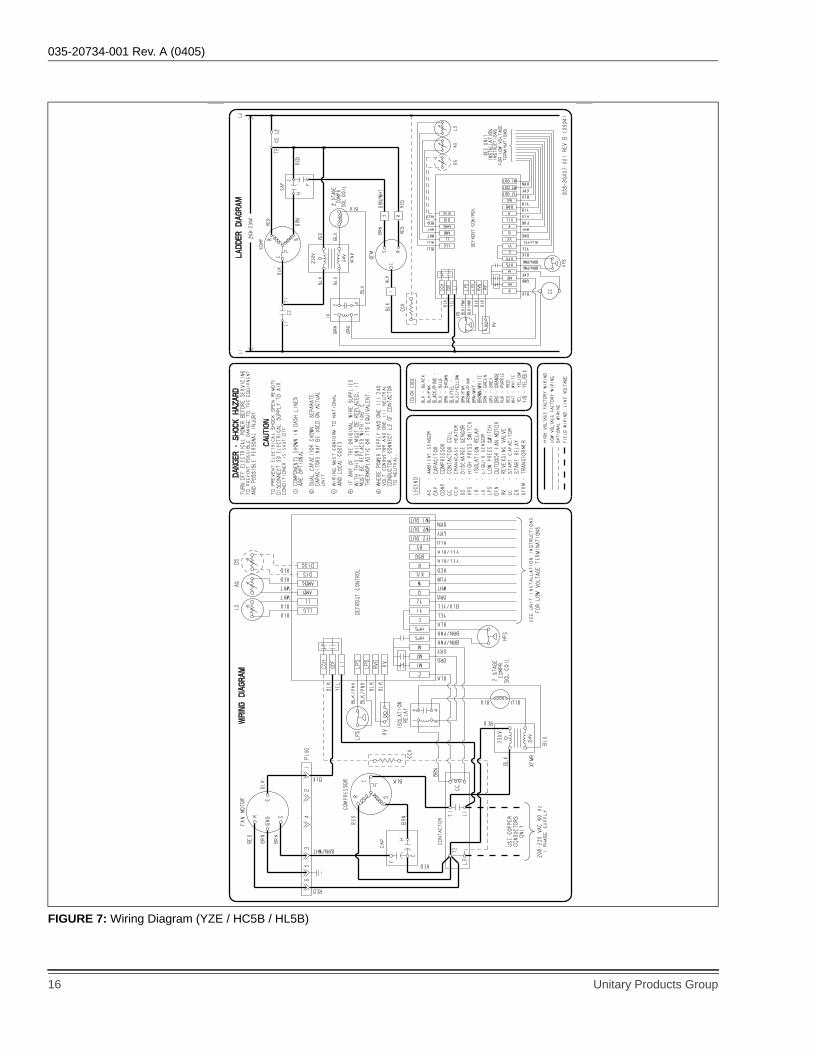
FIGURE 7: Wiring Diagram (YZE / HC5B / HL5B)
035-20734-001 Rev. A (0405)
Unitary Products Group 17
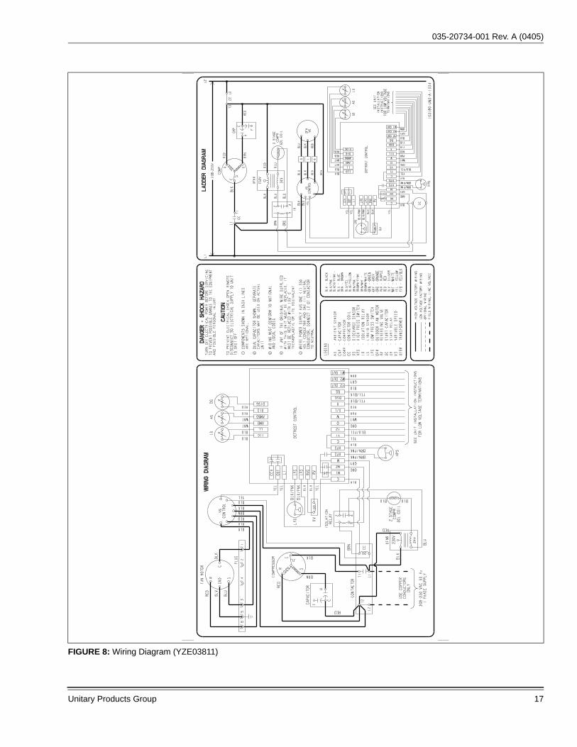
FIGURE 8: Wiring Diagram (YZE03811)

035-20734-001 Rev. A (0405)
18 Unitary Products Group

035-20734-001 Rev. A (0405)
Unitary Products Group 19

Subject to change without notice. Printed in U.S.A. 035-20734-001 Rev. A (0405)Copyright © by York International Corp. 2005. All rights reserved. Supersedes: 035-19986-001 Rev. A (0204)
Unitary 5005 NormanProduct York OKGroup Drive 73069