deluge valve, external resetting - home - … valve, external resetting ... valve size. the...
TRANSCRIPT
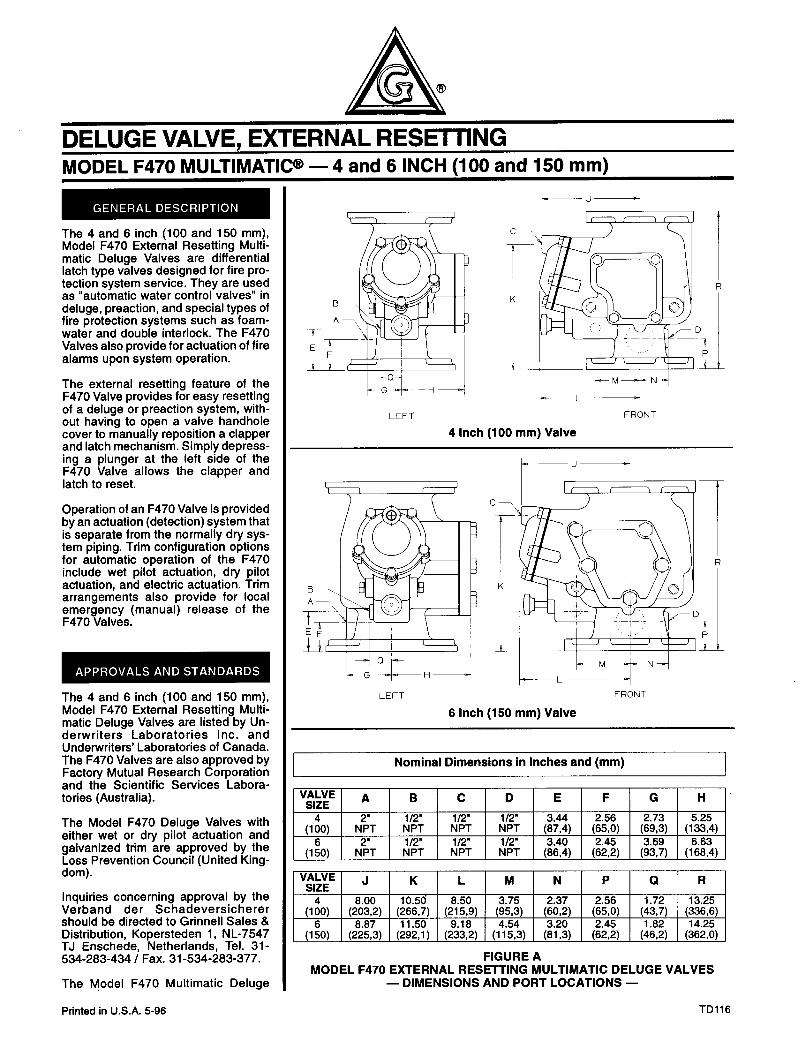
DELUGE VALVE, EXTERNAL RESETTING MODEL F470 MULTIMATIW - 4 and 6 INCH (100 and 150 mm)
The 4 and 6 inch (100 and 150 mm), Model F470 External Resetting Multi- matic Deluge Valves are differential latch type valves designed for fire pro- tection system service. They are used as “automatic water control valves” in deluge, preaction, and special types of fire protection systems such as foam- water and double interlock. The F470 Valves also provide for actuation of fire alarms upon system operation.
The external resetting feature of the F470 Valve provides for easy resetting of a deluge or preaction system, with- out having to open a valve handhole cover to manually reposition a clapper and latch mechanism. Simply depress- ing a plunger at the left side of the F470 Valve allows the clapper and latch to reset.
Operation of an F470 Valve is provided by an actuation (detection) system that is separate from the normally dry sys- tem piping. Trim configuration options for automatic operation of the F470 include wet pilot actuation, dry pilot actuation, and electric actuation. Trim arrangements also provide for local emergency (manual) release of the F470 Valves.
The 4 and 6 inch (100 and 150 mm), Model F470 External Resetting Multi- matic Deluge Valves are listed by Un- derwriters Laboratories Inc. and Underwriters’ Laboratories of Canada. The F470 Valves are also approved by Factory Mutual Research Corporation and the Scientific Services Labora- tories (Australia).
The Model F470 Deluge Valves with either wet or dry pilot actuation and galvanized trim are approved by the Loss Prevention Council (United King- dom).
Inquiries concerning approval by the Verband der Schadeversicherer should be directed to Grinnell Sales & Distribution, Kopersteden 1, NL-7547 TJ Enschede, Netherlands, Tel. 31- 534-263-434 I Fax. 31-534-263-377.
The Model F470 Multimatic Deluge
LEFT
CJ=TN=- FRONT
4 Inch (100 mm) Valve
LEFT FRONT
6 Inch (150 mm) Valve
a
il P
Nominal Dimensions in Inches and (mm)
VALVE A SIZE
&I, NL
$0)
.
N;T
B C
II2 l/2’ NPT NPT
l/2’ l/2’ NPT NPT
D E F G H
l/2’ 3.44 2.56 2.73 5.25 NPT W,4 WV3 (693) (133,4) 112’ 3.40 2.45 3.69 6.63 NPT @W (622) @3,7) (168,4)
VALVE J SIZE K L M N P Q R
$0) (g2) (:& (EPg) ,g, 2.37 2.56 1.72 13.25 WG’) Wd4 (4377) (33636)
$0) (g3) (ky) (&fi) (l%$, (~~~, 2.45 1.82 14.25 W’2) WW WV)
FIGURE A MODEL F470 EXTERNAL RESETTING MULTIMATIC DELUGE VALVES
- DIMENSIONS AND PORT LOCATIONS -
Printed in U.S.A. 5-96 TD116

8
1 -Body 7 - Clapper Latch 8 - O-Ring, # 3-908 9 - Reset
Bushing 10 - O-Ring, t 2-109’ II - Reset Plunger 12 - Reset Knob
13 - Diaphragm Cover Boll, (5 req’d) l/2’ - 13 UNC x I’
14 - Diaphragm Retainer 15 - Flange 8 Push Rod
Assembly 16 - Diaphragm
17 - Diaphragm Housing
18 - i/2’ Pipe Plug (4 req’d)
19 - Bearing (4 req’d) 20 - Clapper Hinge Pin 21 - Latch Hinge Pin
22 - Handhole Cover 23 - Handhole Cover Gasket 24 - Handhole Cover Bolt,
(l/2” - 13 UNC x I-112 4 req’d for 4’ valve) (3/4’ - 11 UNC x 1 -l/2’ 5 req’d for 6’ valve)
- Clapper - Clapper Facing - Clapper Facing
Retainer - Clapper Bolt - Seal Ring
l Lubricated with Dow Coming FS3452 Plurosilicone Grease.
FIGURE B MODEL F470 EXTERNAL RESETTING MULTIMATIC DELUGE VALVE
- ASSEMBLY -
A- BOLT CIRCLE (8 HOLES]
E- HOiE DIAMETER
tSame drilling as for BS 4504 Section 3.2 (PNlO) and DIN 2532 (PNlO).
TABLE A DIMENSIONAL SPECIFICATIONS FOR SELECTION OF FLANGE DRILLING
-2-
300 400 500 700 1000 2000 3000 i 000 2000 3000 5000 7000 10000
FLOW RATE IN GALLONS PER MINUTE (GPM) FLOW RATE IN LITRES PER MINUTE (LPM)
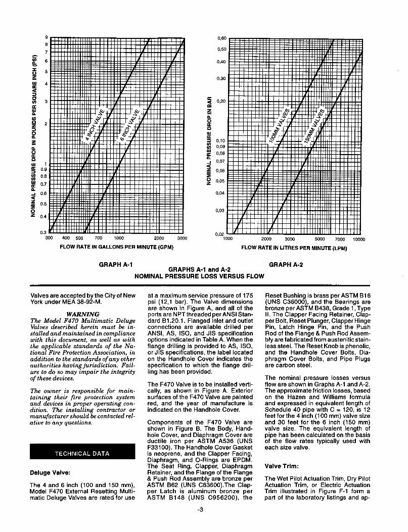
GRAPH A-l GRAPHS A-l and A-2
GRAPH A-2
NOMINAL PRESSURE LOSS VERSUS FLOW
Valves are accepted by the City of New York under MEA 38-92-M.
WARNING The Model F470 Multimatic Deluge Valves described herein must be in- stalled and maintained in compliance with this document, as well as with the applicable standards of the Na- tional Fire Protection Association, in addition to the standards of any other authorities having jurisdiction. Fail- ure to do so may impair the integrity of these devices.
The owner is responsible for main- taining their fire protection system and devices in proper operating con- dition. The installing contractor or manufacturer should be contacted rel- ative to any questions.
Deluge Valve:
The 4 and 6 inch (100 and 150 mm), Model F470 External Resetting Multi- matic Deluge Valves are rated for use
at a maximum service pressure of 175 psi (12,l bar). The Valve dimensions are shown in Figure A, and all of the ports are NPT threaded per ANSI Stan- dard B1.20.1. Flanged inlet and outlet connections are available drilled per ANSI, AS, ISO, and JIS specification options indicated in Table A. When the flange drilling is provided to AS, ISO, or JIS specifications, the label located on the Handhole Cover indicates the specification to which the flange dril- ling has been provided.
The F470 Valve is to be installed verti- cally, as shown in Figure A. Exterior surfaces of the F470 Valve are painted red, and the year of manufacture is indicated on the Handhole Cover.
Components of the F470 Valve are shown in Figure B. The Body, Hand- hole Cover, and Diaphragm Cover are ductile iron per ASTM A536 (UNS F33100). The Handhole Cover Gasket is neoprene, and the Clapper Facing, Diaphragm, and O-Rings are EPDM. The Seat Ring, Clapper, Diaphragm Retainer, and the Flange of the Flange & Push Rod Assembly are bronze per ASTM 862 (UNS C83600).The Clap- per Latch is aluminum bronze per ASTM B148 (UNS C956200), the
-3
Reset Bushing is brass per ASTM B16 (UNS CSSOOO), and the Bearings are bronze per ASTM 8438, Grade 1, Type II. The Clapper Facing Retainer, Clap- per Bolt, Reset Plunger, Clapper Hinge Pin, Latch Hinge Pin, and the Push Rod of the Flange & Push Rod Assem- bly are fabricated from austenitic stain- less steel. The Reset Knob is phenolic, and the Handhole Cover Bolts, Dia- phragm Cover Bolts, and Pipe Plugs are carbon steel.
The nominal pressure losses versus flow are shown in Graphs A-l and A-2. The approximate friction losses, based on the Hazen and Williams formula and expressed in equivalent length of Schedule 40 pipe with C = 120, is 12 feet for the 4 inch (100 mm) valve size and 30 feet for the 6 inch (150 mm) valve size. The equivalent length of pipe has been calculated on the basis of the flow rates typically used with each size valve.
Valve Trim:
The Wet Pilot Actuation Trim, Dry Pilot Actuation Trim, or Electric Actuation Trim illustrated in Figure F-l form a part of the laboratory listings and ap-

90 (27.43)
80 (24.38)
3 z 70 (21,34)
iii k
ki 80 (18,29)
L c‘
3
50 (15,24)
? 40 (12,19)
5 : 30 (9.14)
s E
4
20 (8,lO)
0 (12:) 6 4 & 100 120 140 180 175 1
(83) (8t3) (%7) (11,O) (12,l)
NOTE: IF THE SUPPLY PRESSURE IS VARIABLE, ASSUME MINIMUM EXPECTED VALUE.
SUPPLY PRESSURE, PSI (BAR)
GRAPH B WET PILOT LINE DESIGN CRITERIA
WiTER SUPPLY-iRESSURE
GRAPH C DRY PILOT LINE PRESSURE REQUIREMENTS
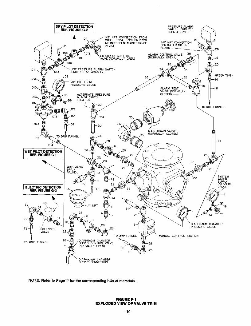
proval of the F470 Valves and are nec- essary fortheir proper operation. Each ;rmage of trim includes the following
l Alarm Control Valve l Automatic Drain Valve l Dry Pilot Line Pressure Gauge
(as applicable)
l Water Supply Pressure Gauge To ease field assembly of the trim ar- l Diaphragm Chamber rangements, the appropriate compo-
Pressure Gauge nents required for Wet Pilot Actuation, l Diaphragm Chamber Connections Dry Pilot Actuation, or Electric l Actuation Devices (as applicable) Actuaton are factory assembled as l Main Drain Valve shown in Figure F-2. l Atarm Test Valve
-4-
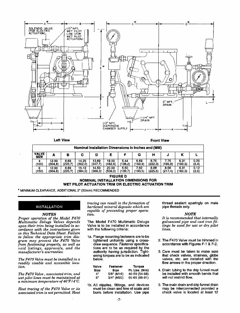
Wet Pilot Actuation (Figure F-l, Items 1 through 35) The Wet Pilot Actuation Trim provides for connection of a detection system consisting of wet pilot sprinklers (heat detectors) and manual control stations interconnected with minimum l/2 inch (15 mm) Schedule 40 steel pipe. The pilot line is connected to the “Wet Pilot Detection” connection shown in Figure F-l. Nominal installation dimensions for the Wet Pilot Actuation Trim are shown in Figure D.
Wet pilot sprinklers are to be minimum l/2 inch (15 mm) orifice listed or ap- proved automatic sprinklers. Manual Control Stations are to be either the Model F180 or F184 described in Tech- nical Data Sheet TD121.
The maximum height of a wet pilot line above the F470 Valve must not exceed the limitations given in Graph B as a function of the minimum water supply pressure to the F470 Valve and the length of the pilot line to the most re- mote pilot sprinkler.
Provision must be made for installing a l/2 inch (15mm) orifice, Inspector’s Test Connection at the most hydrauli- cally demanding location of a wet pilot line (usually adjacent to the highest and most remote wet pilot sprinkler or manual control station).
To determine the most hydraulically demanding location of a wet pilot line, when the choice between two or more locations is not readily apparent, de- termine for each location the elevation above the F470 Valve and the equiva- lent length of fittings plus horizontal pipe from the F470 Valve to the loca- tion. Then, using Graph B, determine the minimum system supply pressure required for the elevation and equiva- lent length of pipe at each location. Interpolate between the equivalent length plots as necessary. The location requiring the highest system supply pressure is the most hydraulically de- manding location for the wet pilot line. (Reference: In no case should the re- quired system supply pressure exceed the actual available minimum ex- pected system supply pressure.)
Operation of a pilot sprinkler or open- ing of a manual control station results in a rapid pressure drop in the Dia- phragm Chamber of the F470 Valve, and the force differential applied through the Clapper Latch which holds the Clapper down in the set position is reduced to below the valve trip point.
NOTES Wet Pilot Lines must be maintained at a minmum temperature of 40%/4”C.
It is recommended that internally gal- vanized pipe and cast iron fittings be used for wet pilot lines.
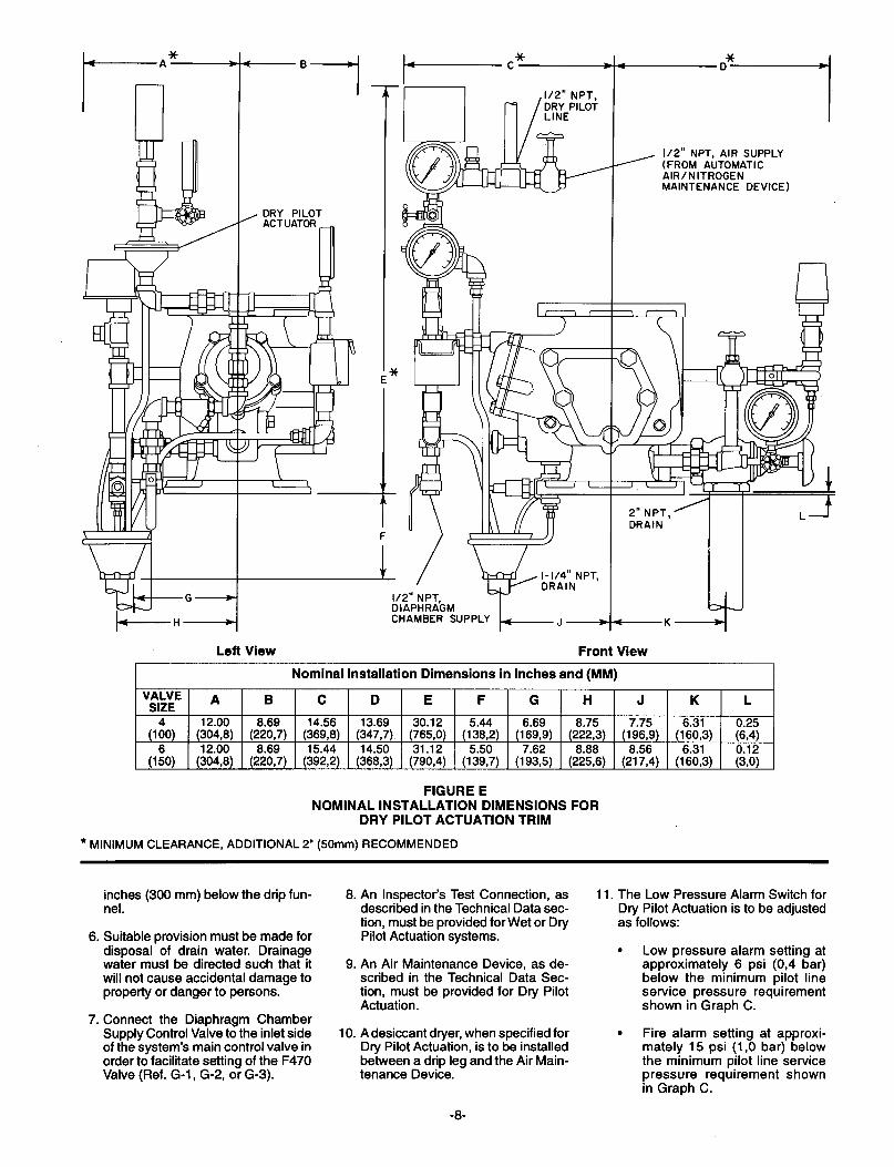
Dry Pilot Actuation (Figure F-l, Items 1 through 35 plus Items Dl through D14) The Dry Pilot Actuation Trim provides for installation of a detection system consisting of dry pilot sprinklers (heat detectors) and manual control stations interconnected with minimum l/2 inch (15 mm) steel pipe. The pilot line, which is to be oressurized with air or nitrogen, is connected to the “Dry Pilot Detection” connection shown in Fiaure F. Provision must be made for a”l/2 inch (15 mm) orifice, Inspector’s Test Connection at the most remote loca- tion from the F470 Valve. Nominal in- stallation dimensions for Dry Pilot Ac- tuation Trim are shown in Figure E.
The Dry Pilot Actuation Trim is pro- vided with a listed and approved Model B-l Dry Pilot Actuator, which is de- scribed in Technical Data Sheet TDll7W. The Actuator is rated for use at a maximum pilot service pressure of 50 psi (3,4 bar) and a maximum water supply service pressure of 175 psi (12,l bar).
Operation of a pilot sprinkler or open- ing of a manual control station, re- leases pneumatic pressure from the pilot line. In turn, the Dry Pilot Actuator opens resulting in a rapid pressure drop in the Diaphragm Chamber of the F470 Valve, and the force differential
applied through the Clapper Latch which holds the Clapper down in the set position is reduced to below the valve trip point.
Dry pilot sprinklers are to be minimum l/2 inch (15 mm) orifice listed or ap- proved automatic sprinklers. Manual Control Stations are to be either the Model Fl80 or F184 described in Tech- nical Data Sheet TDl21.
Graph C shows the “minimum pilot line service pressure” as a function of the water supply pressure. The pressure in the dry pilot actuation system must be automatically maintained using one of the following maintenance devices, as appropriate.
l Model F324 Air Maintenance De- vice (pressure reducing type), refer to Technical Data Sheet TDlll.
l Model F326 Air Maintenance De- vice (compressor control type), refer to Technical Data Sheet TDl12.
l Model F328 Nitrogen Mainte- nance Device (high pressure re- ducing type), refer to Technical Data Sheet TDl13.
NOTES The dewpoint of the pilot line airpres- sure must be maintained below the lowest ambient temperature to which the dry pilot actuation system will be exposed. Accumulation of water in the pilot line connection to the Actuator will lower the air pressure at which the Actuator will open and possibly prevent proper operation. Also, intro- duction of moisture into the pilot lines exposed to freezing temperatures can create an ice buildup which couldpre- vent proper operation of the Actuator
An air dryer must be installed where the moisture content of the air supply is not properly controlled at less than the required value. The desiccant dryer with mounting accessories de- scribed in Technical Data Sheet TD135 is suitable for use with a max- imum inlet pressure of 150 psi (lo,3 bar) and for drying system air down to a dewpoint of less than -2O”Fl-29°C at a pressure of 45 psi (3,l bar) .
It is recommended that an F328 Ni- trogen Maintenance Device be utilized in dry pilot actuation system applica- tions where the dewpoint must be maintained below -2O”Fl-29°C. See Technical Data Sheet TD113.
It is recommended that internallygal- vanized pipe and cast iron fittings be used for dry pilot lines.
Supervision of the pressure in the dry pilot actuation system and/or alarm
-5-
which separately indicates operation of the detection system is recom- mended and may be required by the authority having jurisdiction. A dual setting low pressure alarm switch, such as the unit described in Technical Data Sheet TD210, is suitable for the service. The recommended pressure settings are as follows:
. Low pressure alarm setting at approximately 6 psi (0,4 bar) below the minimum pilot line service pressure requirement shown in Graph C.
. Fire alarm setting at approxi- mately 15 psi (1 ,O bar) below the minimum pilot line service pressure requirement shown in Graph C.
The Pressure Relief Valve (Ref. Item D5 - Fig. F-l) is factory set to relieve at a pressure of approximately 45 psi (3,1 bar); however, it may be field ad- justed to a lower pressure, if required.
Electric Actuation Trim (Figure F-l, Items 1 through 35 plus Items El through E5) The Electric Actuation Trim is required for electric operation of the F470 Valve by a detection system consisting of electrical devices such as heat sensi- tive thermostats, smoke detectors, and/or electric manual pull stations. Information on the various types of So- lenoid Valves that may be used with this trim package is given in Technical Data Sheet TDll9. A listed and ap- proved, 24VDC Solenoid Valve for non-hazardous locations is supplied as standard. Nominal installation di- mensions for the Electric Actuation Trim are shown in Figure D.
NOTE Approval by Factory Mutual is contin- gent on the use of an FM Approved 24VDC Solenoid Valve. FM only ap- proves solenoid valves for use in non- hazardous locations.
The Electric Actuation Trim is only to be used in conjunction with an electric deluge valve releasing panel (auto- matic control unit) that is listed or ap- proved (as appropriate) for fire protec- tion system releasing service. In addition, the deluge valve releasing panel is only to be operated by listed or approved (as approriate) fire detec- tors.
Operation of an electrical device such as a heat sensitive thermostat, smoke detector, or electrical manual control station signals the deluge valve re- leasing panel to energize the Solenoid Valve. In turn, the energized Solenoid Valve opens resulting in a rapid pres- sure drop in the Diaphragm Chamber of the F470 Valve, and the force differ-
ential applied through the Clapper Latch which holds the Clapper down in the set position is reduced to below the valve trip point.
NOTE Consult with the Authority Having Jurisdiction regarding installation criteria pertaining to electric actua- tion circuitry.
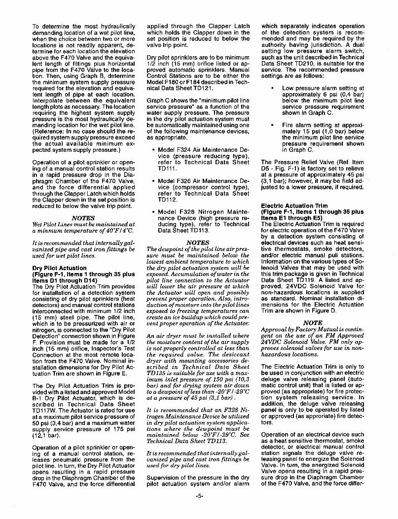
The Model F470 Multimatic Deluge Valve is a differential latch type valve which depends upon water pressure in the Diaphragm Chamber (Ref. Figure C-l) to hold the Clapper closed against the water supply pressure. The nominal trip ratio is 2.5 to 1, i.e., the F470 Valve operates (opens) when the pressure in the Diaphragm Chamber is reduced to approximately 40 percent of the water supply pressure.
When the F470 Valve is set for service, the Diaphragm Chamber is pressur- ized through the trim connections from the inlet side of the system’s main con- trol valve, for example an O.S.&Y. gate valve or butterfly valve (Ref. Figure G-l, G-2, or G-3). Opening of an actu- ation device, for example the solenoid valve in the Electric Actuation Trim (Ref. Fig. G-3), releases water from the Diaphragm Chamber faster than it can be replenished through the l/8 inch (3,2mm) Restriction in the Dia- phragm Chamber Supply Connection. This results in a rapid pressure drop in the Diaphragm Chamber and the force differential applied through the Clap- per Latch to hold the Clapper down in the set position is reduced to below the valve trip point. The water supply pres- sure then forces the Clapper open per- mitting water to flow into the system piping, as well as through the Alarm Port to actuate the system alarms (Ref. Figure C-2).
When the system main control valve is closed to stop waterflow into the sys- tem, the Clapper will be prevented from resetting by the Clapper Latch until the Rest Knob is pushed inward (Ref. Figure C-3). Pushing the Reset Knob inward will temporarily reposition the Clapper Latch away from the wa- terway and allows the Clapper to drop into the seated position.
TO SYSTEM
WATER SUPPLY
- Set Position - Figure C-l
TO SYSTEM
UP
z
z’ ALARM PORT
WATER ‘SUPPLY
- Open Position (Flowing)- Figure C-2
TO SYSTEM I I
WATER ‘SUPPLY
- Open Position (No Flow)- Figure C-3
FIGURE C MODEL F470 EXTERNAL RESETTING MULTIMATIC DELUGE VALVE
- SET AND OPEN POSITIONS -
-6-
SOLENOID VALVE (FOR ELECTRIC
DIAPHRAGM CHAMBER SUPPLY
Left View Front View
* MINIMUM CLEARANCE,
Nominal Installation Dimensions in Inches and (MM)
B C D E F G H J K
8.69 14.25 13.69 19.00 (220,7) (362,0) (347,7) (462,6) (15&‘) (l%;) (~~~) (lk$, (%?5)
6.69 15.12 14.50 20.00 5.50 7.62 8.88 8.56 6.31 (220,7) (384,0) (368,3) (508,O) (139,7) (193,5) (225,6) (217,4) (160,3)
FIGURE D NOMINAL INSTALLATION DIMENSIONS FOR
WET PILOT ACTUATION TRIM OR ELECTRIC ACTUATION TRIM
ADDITIONAL 2’ (50mm) RECOMMENDED
NOTES Proper operation of the Model F470 Multimatic Deluge Valves depends upon their trim being installed in ac- cordance with the instructions given in this Technical Data Sheet. Failure to follow the appropriate trim dia- gram may prevent the F470 Valve from fintioning properly, as well as void listings, approvals, and the manufacturer$ warranties.
The F470 Valve must be installed in a readily visable and accessible loca- tion.
The F470 Valve, associated trim, and wet pilot lines must be maintained at a minimum temperature of 4O”F/4”C.
Heat tracing of the F470 Valve or its associated trim is not permitted. Heat
tracing can result in the formation of hardened mineral deposits which are capable of preventing proper opera- tion.
The Model F470 Multimatic Deluge Valve is to be installed in accordance with the following criteria:
1 a. Flange mounting fasteners are to be tightened uniformly using a cross- draw sequence. Fastener specifica- tions are to be as required by the authority having jurisdiction. Tight- ening torques are to be as indicated below.
Valve Fastener Torque Size Size Ft. Lbs. (Nm)
4” 5/8” (M16) 40-50 (54-68) 6” 314” (M20) 50-65 (68-81)
lb. All nipples, fittings, and devices must be clean and free of scale and burrs before installation. Use pipe
-7-
thread sealant sparingly on male pipe threads only.
NOTE It is recommended that internally galvanized pipe and cast iron fit- tings be used for wet or dry pilot lines.
2. The F470 Valve must be trimmed in accordance with Figures F-l & F-2.
3. Care must be taken to make sure that check valves, strainers, globe valves, etc. are installed with the flow arrows in the proper direction.
4. Drain tubing to the drip funnel must be installed with smooth bends that will not restrict flow.
5. The main drain and drip funnel drain may be interconnected provided a check valve is located at least 12
-B
-I
, DRY PILOT ACTUATOR
DIAPHRAGM CHAMBER SUPPL
112” NPT AIR SUPPLY ’ (FROM AbTOMATlC
AIR/NITROGEN MAINTENANCE DEVICE)
2” NPT. DRAIN
Left View Front View
Nominal Installation Dimensions in Inches and (MM)
FIGURE E NOMINAL INSTALLATION DIMENSIONS FOR
DRY PILOT ACTUATION TRIM
* MINIMUM CLEARANCE, ADDITIONAL 2’ (50mm) RECOMMENDED
inches (300 mm) below the drip fun- nel.
6. Suitable provision must be made for disposal of drain water. Drainage water must be directed such that it will not cause accidental damage to property or danger to persons.
7. Connect the Diaphragm Chamber Supply Control Valve to the inlet side of the system’s main control valve in order to facilitate setting of the F470 Valve (Ref. G-l, G-2, or G-3).
8. An Inspector’s Test Connection, as described in the Technical Data sec- tion, must be provided for Wet or Dry Pilot Actuation systems.
9. An Air Maintenance Device, as de- scribed in the Technical Data Sec- tion, must be provided for Dry Pilot Actuation.
10. Adesiccant dryer, when specified for Dry Pilot Actuation, is to be installed between a drip leg and the Air Main- tenance Device.
11. The Low Pressure Alarm Switch for Dry Pilot Actuation is to be adjusted as follows:
. Low pressure alarm setting at approximately 6 psi (0,4 bar) below the minimum pilot line service pressure requirement shown in Graph C.
. Fire alarm setting at approxi- mately 15 psi (1 ,O bar) below the minimum pilot line service pressure requirement shown in Graph C.
-8-
12. Unused pressure alam switch con- nections must be plugged.
13. The Pressure Relief Valve provided with the Dry Pilot Actuation Trim is factory set to relieve at a pressure of approximately 45 psi (3,1 bar), which can typically be used for a maximum normal dry pilot actuation system pressure of 40 psi (2,8 bar). The Pressure Relief Valve mav be reset; however, it must be be rkset to relieve at a pressure which is in accordance with the requirements of the authority havng jurisdiction.
To reset the Pressure Relief Valve, first loosen the jam nut and then adjust the cap accordingly - clock- wise for a higher pressure setting or counterclockwise for a lower pres- sure setting. After verifying the de- sired pressure setting, tighten the jam nut.
14. Conduit and electrical connections are to be made in accordance with the requirements of the authority having jurisdiction and/or the Na- tional Electric Code.
Steps 1 through 12 are to be per- formed when initially setting the Model F470 Multimatic Deluge Valve; after an operational test of the fire protection system; or, after system operation due to a fire.
1. Close the Diaphragm ChamberSup- ply Control Valve.
2. Close the Main Control Valve, and if the system is equipped with Dry Pilot Actuation, close the Air Supply Con- trol Valve (Ref. Figure F-l).
3. Open the Main Drain Valve and all auxiliary drains in the system. Close the auxiliary drain valves after water ceases to discharge. Leave the Main Drain Valve open.
4. Depress the plunger of the Auto- matic Drain Valve to verify that it is open and that the F470 Valve is completely drained.
5. Push the Reset Knob inward to allow the Clapper to reseat.
Under normal circumstances, the re- seating of the Clapper can be heard; however, during an annual operation test procedure, for example, due to minimal flow through a partially opened main control valve, the Clap- per may not latch open as shown in Figure C-3. In which case the reseat-
ing sound of the Clapper will not be heard.
Also under normal circumstances, water pressure in the riser will have exerted sufficient force on the Dia- phragm so as to have emptied most of the water from the Diaphragm Chamber which, in turn, will ease the pushing of the Reset Knob by eliminating the resistive force pro- duced by a water filled Diaphragm Chamber. Therefore, should water remain in the Diaphragm Chamber, the Reset Plunger will need to be depressed with added force to push the remaining water out of the Dia- phragm Chamber and through an open actuation device (e.g., a Dry Pilot Actuator or Solenoid Valve).
NOTE Zf the Reset Knob can not be de- pressed sufficiently to allow the Clapper to reseat, operate (open) the Manual Control Station and then once again push the Reset Knob with sufficient force to push the water out of the Diaphragm Chamber through the Manual Control Station drain.
Clean the Strainer in the Diaphragm Chamber Supply connection by re- moving the clean-out plug and strainer basket. The Strainer may be flushed out by momentarily opening the Diaphragm Chamber Supply Control Valve.
Open the Alarm Control Valve (Fig. F-l), if it was closed to silence local alarms.
It is recommended that the Alarm Control Valve be wire sealed in the open position with a No. 16 twisted wire, the ends of which are secured by a lead seal. The wire seal should be looped through the hole in the handle and tightly twisted around the pipe nipple adjacent to the handle.
Reset the actuation system.
Manual Actuation - Push the oper- ating lever up; however, do not close the hinged cover at this time.
Wet Pilot Actuation - Replace oper- ated pilot sprinklers and/or reset the manual control stations.
Dry Pilot Actuation - Replace oper- ated pilot sprinklers and/or reset the manual control stations. Re-estab- lish dry pilot pneumatic pressure.
Electric Actuation - Reset the elec- tric detection system in accordance with the manufacturer’s instructions to de-energize the solenoid valve.
NOTE In order to prevent the possibility
-9-
of a subsequent operation of an overheated solder type pilot sprinkler, any solder type pilot sprinklers which were possibly ex- posed to a temperature greater than their maximum rated ambi- ent must be replaced.
9. Open the Diaphragm Chamber Sup- ply Control Valve and allow time for full pressure to build up in the Dia- phragm Chamber.
10. Operate (open) the Manual Control Station to venttrapped air from the Diaphragm Chamber. If necessary, first open the hinged cover, and then fully pull down on the operating lever. SLOWLY close the operating lever, by pushing it up, after aerated water ceases to discharge from the Manual Control Station drain tubing. Close the hinged cover and insert a new break rod in the small hole through the top of the enclosing box.
11.
12.
If wet pilot actuation is being used, crack open the Inspector’s Test Con- nection and any other vent valves, to relieve trapped air. After the dis- charge of air has stopped, close the vent valves and the Inspector’s Test Connection.
Inspect drain connections from the Manual Control Station, Solenoid Valve, Dry Pilot Actuator, and Alarm Devices, as applicable. Any leaks must be corrected before proceed- ing to the next step.
Slowly open the Main Control Valve. Close the Main Drain Valve as soon as water discharges from the drain connection. Observe the Automatic Drain Valve for leaks. If there are leaks, determine/correct the cause of the leakage problem. If there are no leaks, the F470 Valve is ready to be placed in service and the Main Control Vave must then be fully opened.
NOTE After setting a fire protection system, notify the proper authorities and ad- vise those responsible for monitoring proprietary and /or central station alarms.
DRY PILOT DETECTION REF. FIGURE G-2
PRESSURE ALARM /“... SWITCH (ORDERED SEPARATELY)
f-., -. i I/:
l/2” NPT CONNECTION FROM MODEL F324. F326. OR F328 21 AIR (NITROGEN) MAINTENANCE 3/4” NPT CONNECTION DEVICE ;F;RW;TER MOTOR
PPLY CONTROL (NORMALLY OPEN)
LOW PRESSURE ALARM SWITCH (ORDERED SEPARATELY)
81 AE)L” PC-,hlTE)AI -L-I,,,, ““I. I ll”L “AL,,E (NORMALLY OPEN: 28
28 25
.D I I
D 13
DIO
DRY PILOT LINE PRESSURE GAUGE
77 (GREEN TINT)
--c/ / \ I4
ALTERNATE PRESSURE ALARM SWITCH Dl
D6 LOCATION Dl I la7n /
D9
D7
TO DRlb FUNNEL GA/24
ELECTRIC DETECTION REF. FIGURE G-3 (
DIAPHRAGM CHAMBER PRESSURE GAUGE
TO DRIP FUNNEL MANUAL CONTROL STATION
DRIP FUNNEL
T TO DRIP FUNNEL
28
5
DIAPHRAGM CHAMBER SUPPLY CONTROL VALVE (NORMALLY OPEN)
28
23
DIAPHRAGM CHAMBER SUPPLY CONNECTION
NOTE: Refer to Pagel 1 for the corresponding bills of materials.
FIGURE F-l EXPLODED VIEW OF VALVE TRIM
-lO-
1 - 300 lb. Water Pres- sure Gauge (2 req’d)
2 - 114’ Gauge Test Valve
3 - Model F180 Manual Control Station
31 - 112’ x 5’ Nipple (2 req’d)
32 - 112 x 7-l/2 Nipple
4 - 2’ Angle Valve 5 - l/2’ Ball Valve
(2 req’d) 6 - l/2’ Swing Check
Valve 7 - l/2’ spring
Loaded Check Vafve
33 - 112’ x 10-112’ Nipple for 4” valve, 112’ x 12’ Nipple for 6’ valve
34 - 114” x l-112 Nipple
35 -2x3 Nipple (2 req’d)
6 - Priming Supply Re- striction
9 - i/2’ Y-Strainer 10 - Model F793
Automatic Drain Valve
11 - Drip Funnel support Plug
12 - Drip Funnel support
13 - Drip Funnel 14 - 3132’ Vent
Fitting 15 - t/2’ Angle
Valve 16 - l/4’ Tube,
30’ long 17 - i/2’ Tube
Connector 18 - l/2’ Tube,
24’ long 19 - l/4’ Plug 20 - l/2’ Plug 21 - 3/4’ Plug 22 - l/2’ Union
(5 req’d) 23 - l/2’ 90’ Elbow (3
req’d) 24 - l/2’ Tee (6 req’d) 25 - 1l2’x ll4’X 112’
Tee (3 req’d) 26 - f/2’ x l/2” x 3l4
Tee
Dl - Model B-l Dry Pilot Actuator
D2 - 250 lb. Air Pressure Gauge
D3 - l/4’ Gauge Test Valve
D4 - l/2’ Globe Valve
D5 - l/4’ Pressure Relief Valve
D6 - l/4’ Plug D7 - l/2’ Tube
Connector D0 - t/2’ Tube,
24’ long D9 - l/2’ 90’ Elbow
(2 req’d) DIO - 112’ x 112’ x 114’
Tee (2 req’d) Dll - 112’ Tee
(2 req’d) D12 - t/4’ x1-112
Nipple D13 - 112.x t-112”
Nipple (7 req’d)
D14 - 112’ x 3’ Nipple
27 - 2’ 90’ Elbow 20 - 112’ x l-112’
Nipple (17 req’d)
29 - 112” x 3’ Nipple
30 - i/2” x 4’ Nipple
El - 112’ 90’ Elbow E2 - l/2’ Tube
Connector E3 - i/2” Tube,
24’ long E4 - 112’ x t-112’
Nipple (2.req.d)
E5 - 24VDC Solenoid Valve
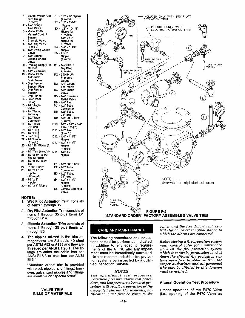
NOTES: 1. Wet Pilot Actuation Trim consists
of Items 1 through 35.
2. Dry Pilot Actuation Trim consists of Items 1 through 35 plus Items Dl through D14.
3. Electric Actuation Trim consists of items 1 through 35 plus Items El through E5.
4. The nipples utilized in the trim ar- rangements are Schedule 40 steel per ASTM A53 or Al 35 and they are threaded per ANSI B1.20.1 The fit- tings are either malleable iron per ANSI 816.3 or cast iron per ANSI 816.4.
“Standard order” trim is provided with black nipples and fittings: how- ever, galvanized nipples and fittings are available on “special order”.
VALVE TRIM BILLS OF MATERIALS
-INCLUDED ONLY WITH DRY PILOT ACTUATION TRIM
INCLUDED ONLY WITH ELECTRIC ACTUATION TRIM
?
TUBE TD DRIP
NOTE Assemble in alohabetical order.
FIGURE F-2 “STANDARD ORDER” FACTORY ASSEMBLED VALVE TRIM
The following procedures and inspec- tions should be perform as indicated, in addition to any specific require- ments of the NFPA, and any impair- ment must be immediately corrected. It is also recommended that fire protec- tion systems be inspected by a quali- fied Inspection Service.
NOTES The operational test procedure, waterflow pressure alarm test proce- dure, and low pressure alarm test pro- cedure will result in operation of the associated alarms. Consequently, no- tification must first be given to the
-ll-
owner and the fire department, cen- tral station, or other signal station to which the alarms are connected.
Before closing a fire protection system main control valve for maintenance work on the fire protection system which it controls, permission to shut down the effected fire protection sys- tems must first be obtained from the proper authorities and all personnel who may be affected by this decision must be notified.
Annual Operation Test Procedure
Proper operation of the F470 Valve (i.e., opening of the F470 Valve as

INSPECTOR’S SYSTEM PIPING WITH OPEN NOZZLES OR SPRINKLERS-NORMALLY DRY REMOTE TEST
MANUAL CONNECTION
CONTROL IAT THE MOST
STAT I ON HYDRAULICALLY
(WHEN DEMAND I NG
SPECIFIED1 LOCATION OF THE
f\ / WET PILOT LINE)
WET PILOT SPRINKLER DETECTION SYSTEM /
DRAIN DRAIN
’ --WATERFLOW Cm?--, /-r
DIAPHRAGM CHAMBER SUPPLY
CONTROL VALVE
(NORMALLY
DRAIN
x-
MAIN CONTROL VALVE [NORMALLY OPEN1
OPEN 1
DIAPHRAGM CHAMBER SUPPLY CONNECTION
WATER SUPPLY
FIGURE G-l DELUGE VALVE SYSTEM SCHEMATIC
-WET PILOT ACTUATION-
INSPECTOR’S
SYSTEM PIPING WITH OPEN NOZZLES OR SPRINKLERS-NORMALLY DRY REMOTE TEST
MANUAL CONNECTION
CONTROL IAT THE MOST
STAT ION REMOTE
I WHEN LOCATION
4 4 4 4 4 SPECIFIED1 FROM THE
/h / F470 VALVEI
DRY PILOT SPRINKLER DETECTION SYSTEM LOW PRESSURE (MINIMUM I/Z”PIPE AND AUTOMATIC SPRINKLERS1
/
ALARM SWITCH D I APHRAGM
DRY PILOT ACTUATOR
TO ATMOSPHERE
AUTOMAT I C AIR/NITROGEN MAINTENANCE
DEV ICE
LOCAL MANUAL
CONTROL STAT I ON
RESTRICTION WATERFLOW PRESSURE
ALARM SWITCH
DRAIN MA[N DRAIN
MODEL F470 DELUGE VALVE
D I APHRAGM CHAMBER SUPPLY
CONTROL--- VALVE
I NORMALLY OPEN 1
DRAIN
WATER SUPPLY
MAIN CONTROL VALVE (NORMALLY OPENI
DRAIN
DIAPHRAGM CHAMBER SUPPLY CONNECTION
WATER SUPPLY
FIGURE G-2 DELUGE VALVE SYSTEM SCHEMATIC
- DRY PILOT ACTUATION-
-12-
T SYSTEM PIPING WITH OPEN NOZZLES OR SPRINKLERS-NORMALLY DRY
\
ELECTRIC DETECTION SYSTEM (TYPICALLY 24 VOLTS DC1
HEAT DETECTORS, SMOKE DETECTORS, MANUAL PULL STATIONS, ETC.
(TYPICALLY 24 VOLTS DCI
, D I APHRAGM CHAMBER
PRESSURE GAUGE
POWER SUPPLY
(TYPICALLY 120 VOLTS ACI
RESTRICTION WATERFLOW PRESSURE
ALARM SWITCH
DRAIN MAIN DRAIN MODEL F470 DELUGE VALVE
D I APHRAGM CHAMBER SUPPLY
CONTROL VALVE
(NORMALLY OPEN)
DRAIN
\
WATER SUPPLY
MAIN CONTROL VALVE [NORMALLY OPEN1
DIAPHRAGM CHAMBER SUPPLY CONNECTIONi I
WATER SUPPLY
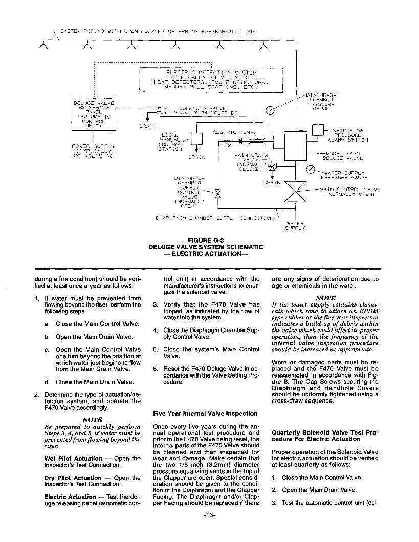
FIGURE G-3 DELUGE VALVE SYSTEM SCHEMATIC
- ELECTRIC ACTUATION-
during a fire condition) should be veri- fied at least once a year as follows:
If water must be prevented from flowing beyond the riser, perform the following steps.
a. Close the Main Control Valve.
b. Open the Main Drain Valve.
c. Open the Main Control Valve one turn beyond the position at which water just begins to flow from the Main Drain Valve.
d. Close the Main Drain Valve.
Determine the type of actuation/de- tection system, and operate the F470 Valve accordingly.
NOTE Be prepared to quickly perform Steps 3, 4, and 5, if water must be prevented from flowing beyond the riser
Wet Pilot Actuation - Open the Inspector’s Test Connection.
Dry Pilot Actuation - Open the Inspector’s Test Connection.
Electric Actuation - Test the del- uge releasing panel (automatic con-
trol unit) in accordance with the manufacturer’s instructions to ener- gize the solenoid valve.
Verify that the F470 Valve has tripped, as indicated by the flow of water into the system.
Close the Diaphragm ChamberSup- ply Control Valve.
Close the system’s Main Control Valve.
Reset the F470 Deluge Valve in ac- cordance with the Valve Setting Pro- cedure.
Five Year Internal Valve Inspection
Once every five years during the an- nual operational test procedure and prior to the F470 Valve being reset, the internal parts of the F470 Valve should be cleaned and then inspected for wear and damage. Make certain that the two l/8 inch (3,2mm) diameter pressure equalizing vents in the top of the Clapper are open. Special consid- eration should be given to the condi- tion of the Diaphragm and the Clapper Facing. The Diaphragm and/or Clap- per Facing should be replaced if there
-13-
are any signs of deterioration due to age or chemicals in the water.
NOTE If the water supply contains chemi- cals which tend to attack an EPDM type rubber or the five year inspection indicates a build-up of debris within the valve which could affect its proper operation, then the frequency of the internal valve inspection procedure should be increased as appropriate.
Worn or damaged parts must be re- placed and the F470 Valve must be reassembled in accordance with Fig- ure B. The Cap Screws securing the Diaphragm and Handhole Covers should be uniformly tightened using a cross-draw sequence.
Quarterly Solenoid Valve Test Pro- cedure For Electric Actuation
Proper operation of the Solenoid Valve for electric actuation should be verified at least quarterly as follows:
1. Close the Main Control Valve.
2. Open the Main Drain Valve.
3. Test the automatic control unit (del-

uge releasing panel) in accordance with the manufacturer’s instructions to energize the solenoid valve.
Verify that the flow of water from the Solenoid Valve drain connection in- creases to a full flow.
Verify that the Diaphragm Chamber pressure has decreased to below 25% of the water supply pressure.
Reset the electric detection system in accordance with the man- ufacturer’s instructions to de-ener- gize the solenoid valve. Check the Solenoid Valve drain for leaks. Any leaks must be corrected before pro- ceeding to the next step.
Slowly open the Main Control Valve. Close the Main Drain Valve as soon as water discharges from the drain connection. Observe the Automatic Drain Valve for leaks. If there are leaks, determine/correct the cause of the leakage problem. If there are no leaks, the F470 Valve is ready to be placed in service and the Main Control Vave must then be fully opened.
Quarterly Dry Pilot Actuator Test Procedure For Dry Pilot Actuation
Proper operation of the Dry Pilot Actu- ator for dry pilot actuation should be verified at least quarterly as follows:
1.
2.
3.
4.
5.
6.
7.
Close the Main Control Valve.
Open the Main Drain Valve.
Open the Inspector’s Test Connec- tion on the Dry Pilot Line.
Verify that the flow of water from the Dry Pilot Actuator drain connection increases to a full flow.
Verify that the Diaphragm Chamber pressure has decreased to below 25% of the water supply pressure.
Close the Inspector’s Test Connec- tion and allow the dry pilot line pres- sure to re-establish. Check the Dry Pilot Actuator drain for leaks. Any leaks must be corrected before pro- ceeding to the next step.
Slowly open the Main Control Valve. Close the Main Drain Valve as soon as water discharges from the drain connection. Observe the Automatic Drain Valve for leaks. If there are leaks, determine/correct the cause of the leakage problem. If there are no leaks, the F470 Valve is ready to be placed in service and the Main Control Vave must then be fully opened.
Quarterly Waterflow Alarm Test Pro- cedure
Testing of the system water-flow alarms should be performed quarterly. To test the waterflow alarm, open the Alarm Test Valve, which will allow a flow of water to the Pressure Alarm Switch and/or Water Motor Alarm. Upon satis- factory completion of the test, close the Alarm Test Valve.
Quarterly Low Pressure Alarm Test Procedure And Condensate Drain Procedure For Dry Pilot Actuation
For Dry Pilot Actuation, testing of the Low Pressure Alarm Switch and drain- age of the pilot line condensate should be
1.
performed quarterly as follows.
Close the Diaphragm Chamber Sup- ply Control Valve.
2.
3.
4.
5.
6.
7.
8.
Close the Main Control Valve.
Open the Main Drain Valve.
Drain the dry pilot line condensate as follows.
a. Close the Gauge Test Valve -located below the Dry Pilot Line Pressure Gauge.
b. Remove the l/4” Plug from the Gauge Test Valve.
c. Crack Open the Gauge Test Valve and allow all conden- sate, if any, to drain out.
d. Close the Gauge Test Valve, replace the Plug, and then open the Gauge Test Valve.
Open the Inspector’s Test Connec- tion, and slowly relieve pneumatic pressure. Verify that the Low pres- sure Alarm Switch is operational and that the low pressure set points are as follows:
. Low pressure alarm setting at approximately 6 psi (0,4 bar) below the minimum pilot line service pressure requirement shown in Graph C.
. Fire alarm setting at approxi- mately 15 psi (1 ,O bar) below the minimum pilot line service pressure requirement shown in Graph C.
Close the Inspector’s Test Connec- tion, and allow the Dry Pilot Line to automatically repressurize.
Open the Diaphragm Chamber Sup- ply Control Valve.
Slowly open the Main Control Valve. Close the Main Drain Valve as soon as water discharges from the drain
-14-
connection. Observe the Automatic Drain Valve for leaks. If there are leaks, determine/correct the cause of the leakage problem. If there are no leaks, fully open the Main Control Valve.
Seller warrants for a period of one year from the date of shipment (warranty period) that the products furnished hereunder will be free from defects in material and workmanship.
For further details on Warranty, see Price List.
All orders for Model F470 Multimatic Deluge Valves, trim, accessories, and replacement parts must include the description and Product Symbol Num- ber (PSN), where applicable.
Valves:
Unless otherwise specified, the F470 Valves will be provided with ANSI flange drilling.
Specify: (specify size) Model F470 Ex- ternal Resetting Multimatic Deluge Valve with (specify abbreviation - refer to Table A, Page 2) flange drilling, PSN (specify).
ANSI
4’ (100 mm) . . . . . . PSN 52-470-l-013 6” (150 mm) . . . . PSN 52-470-l-015
IS0
4’ (100 mm) . . . . . . PSN 52-470-4-l 13 6’ (150 mm) . . . . , PSN 52-470-4-115
AS
4’ (100 mm) . . . . . . . . PSN 52-470-4-313 6’ (150 mm) . , PSN 52-470-4-315
JIS
4” (100 mm) . . . . . . PSN 52-470-4-713 6’ (150 mm) . . . . . . . PSN 52-470-4-715
Trim:
Unless otherwise specified, all trim ar- rangements are provided factory as- sembled as shown in Figure F-2. Un- assembled trim packages as shown in Figure F-l can be provided on “special order”. Product Symbol Numbers (PSN) need not be specified when or- dering unassembled trim.
“Standard Order” Accessories: Factory Assembled Black Trim:
Specify: Factory assembled black (specify type trim) for use with the Model F470 Multimatic External Re- setting Deluge Valve, PSN (specify).
Refer to the following Technical Data Sheets (TD), as applicable.
Pressure Alarm Switch . . Low Pressure Alarm Switch . Model F324 Air Maintenance
Device . . . . . . . . Model F326 Air Maintenance
Device . Model F326 Nitrogen Maintenance
Device . Desiccant Dryer . . Model F160 or F164
Wet Pilot Actuation Trim . .
Dry Pilot Actuation Trim . .
Electric Actuation Trim With 24VDC Solenoid Valve
.PSN 52-470-l-101
PSN 52-470-I -102
.PSN 52-470-t-103 Manual Control Stations TD121
“Special Order” Factory Assembled Galvanized Trim:
Specify: Factory assembled galva- nized (specify type trim) for use with the Model F470 Multimatic External Resetting Deluge Valve, PSN (spec- ify).
Wet Pilot Actuation Trim .PSN 52-470-2-101
Dry Pilot Actuation Trim .PSN 52-470-2-102
Electric Actuation Trim With 24VDC Solenoid Valve PSN 52-470-2-103
“Special Order” Electric Actuation Trim With Separately Ordered Sole- noid Valve:
Specify: (Specify Factory assembled or Unassembled), (specify black or galvanized) Electric Actuation Trim With Separately Ordered Solenoid Valve for use with the Model F470 Multimatic External Resetting Deluge Valve.
When ordering “Electric Actuation Trim With Separately Ordered Solenoid Valve”, refer to Technical Data Sheet TD119 for information on separately ordered, UL Listed Solenoid Valves that may be suitable for use in hazard- ous locations or that have voltage rat- ings other than 24VDC.
NOTE Factory Mutual Approval for electric actuation of the F470 Valve is contin- gent on the’ use of the FM Approved 24VDC Solenoid Valve provided with the “Standard Order” Electric Actua- tion Wm, PSN 52-470-l-103 or PSN 52-470-2-103.
TD213 TD210
TDIII
TD112
TD113 TD135
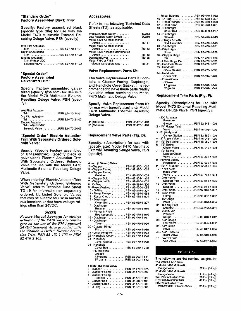
Valve Replacement Parts Kit:
The Valve Replacement Parts Kit con- tains a Clapper Facing, Diaphragm, and Handhole Cover Gasket. It is rec- ommended to have these parts readily available when servicing the Model F470 Multimatic Deluge Valve.
Specify: Valve Replacement Parts Kit for use with (specify size) inch Model F470 Multimatic External Resetting Deluge Valve.
4” (100 mm) PSN 92-470-I-101 6’ (150 mm) . . PSN 92-470-I-102
Replacement Valve Parts (Fig. B):
Specify: (description) for use with (specify size) Model F470 Multimatic External Resetting Deluge Valve, PSN (specify).
4 inch (100 mm) Valve 2 - Clapper 3 - Clapper Facing 4 - Clapper Facing
Retainer 5 - Clapper Bolt . 7 - Clapper Latch . 6 - O-Ring . . . . . . . . . . 9 - Reset Bushing IO-O-Ring . . .._.... 11 - Reset Plunger. 12-ResetKnob...... 13 - Diaphragm
Cover Bolt 14 - Diaphragm
Retainer 15 - Flange & Push
Rod Assembly 16 - Diaphragm 17 - Diaphragm
Cover 20 - Clapper Hinge
Pin . . . . . . . . . . 21 - Latch Hinge Pin 22 - Handhole Cover 23 - Handhole
Cover Gasket 24 - Handhole
Cover Bolt - Flurosilicone
Grease
PSN 92-470-I -006 PSN 92-470-I-009
PSN 92-470-I -004 . PSN 62-634-l -109
PSN 92-470-I -005 PSN 62-576-l -306 PSN 92-470-I -052 PSN 62-576-l -307 PSN 92-470-I -053 PSN 62-470-I-001
PSN 62-039-I -207
. PSN 92-470-I -049
PSN 92-470-I -040 PSN 92-470-I-031
PSN 92-470-I -029
PSN 92-470-l-036 PSN 92-470-I -023 PSN 92-470-I -002
PSN 92-470-I -008
PSN 62-039-l-206
1.5grams . . . . PSN 92-302-l-641 57 grams PSN 92-302-l -642
6 inch (150 mm) Valve 2 _ Clapper , PSN 92-470-I -025 3 - Clapper Facing PSN 92-470-I-032 4 - Clapper Facing
Retainer PSN 92-470-I-026 5 - Clapper Bolt PSN 62-634-I-109 7 - Clapper Latch PSN 92-470-I-030 6 - O-Ring PSN 62-576-l -306
-15-
9 - Reset Bushing ......... .PSN 92-470-l-052 10 -O-Ring .............. .PSN 62-578-l-307 11 - Reset Plunger ........ .PSN 92-470-I-053 12 - Reset Knob .......... .PSN 62-470-I-001 13 - Diaphragm
Cover Bolt .......... .PSN 62-039-l -207 14 - Diaphragm
Retainer ............ .PSN 92-470-I-049 15 - Flange 8 Push
Rod Assembly ....... .PSN 92-470-I -040 16 - Diaphragm ........... .PSN 92-470-I-031 17 - Diaphragm
Cover . . . . . . . . . . . . . .PSN 92-470-I -029 20 - Clapper Hinge
Pin . . . . . . . . . . 21 - Latch Hinge Pin 22 - Handhole Cover 23 - Handhole
Cover Gasket . . 24 - Handhole
Cover Bolt . - Flurosilicone
Grease
..... .PSN 92-470-I-039
..... .PSN 92-470-I-023
..... .PSN 92-470-I -021
..... .PSN 92-470-I-033
..... .PSN 62-634-I-407
1.5grams..... ..... .PSN 92-302-i-641 57 grams . . . ..... .PSN 92-302-I -642
Replacement Trim Parts (Fig. F):
Specify: (description) for use with Model F470 External Resetting Multi- matic Deluge Valve, PSN (specify).
1 - 300 lb. Water Pressure Gauge . . . . . . .PSN 92-343-l -005
2 - l/4’ Gauge Test Valve . , . .PSN 46-005-I -002
3 - F160 Manual Control Station . . . .PSN 52-289-1-001
4 - 2” Angle Valve . . .PSN 46-048-l-009 5 - l/2’ Ball Valve . . .PSN 46-050-I-004 6 - 112” Swing
Check Valve .PSN 46-049-I-004 7 - 112’ Spring
Loaded Check Valve . . . .PSN 92-322-l -002
6 - Priming Supply Restriction . . . . .PSN 92-020-I-009
9 - 112” Y-Strainer . . . .PSN 52-353-l-005 10 - F793 Auto-
matic Drain Valve . . . .PSN 52-793-lGO4
II - Drto Funnel Support Plug . .PSN 92-211-1-005
12 - Drio Funnel Support . . . . .PSN 92-21 i-I-003
13 - Drip Funnel . .PSN 92-343-l-007 14 - 3/32’ Vent
Fitting . . . .PSN 92-032-I-002 15 - l/2’ Angle
Valve . . . . .PSN 46-046-l -004 Dl - B-l Dry Pilot
Actuator . . .PSN 52-260-1-001 D2 - 250 lb. Air
Pressure Gauge .PSN 92-343-l-012
D3 - l/4” Gauge Test Valve .PSN 46-005-I -002
D4 - l/2’ Globe Valve . . . .PSN 46-047-I -004
D5 - l/4’ Pressure Relief Valve . . .PSN 92-343-l -020
E5 - 24VDC Sole- noid Valve . . . . .PSN 52-267-l -024
The following are the nominal weights for the valves and trim: 4’ Model F470 Multimattc
Deluge Valve . . . 77 Ibs. (35 kg) 6” Model F470 Multimatic
Deluge Valve 111 Ibs. (49 kg) Wet Pilot Actuation Trim . Dry Pilot Actuation Trim . . . .
26 Ibs. (13 kg) 41 Ibs. (16 kg)
Electric Actuation Trim With 24VDC Solenoid Valve . 33 Ibs. (15 kg)

0 Reg. trademark of GRINNELL CORPORATION, 3 TYCO PARK, EXETER, NH 03833 A tqC0 INTERNATIONAL LTD. COMPANY