delta p hazards - canadian association of diving contractors
TRANSCRIPT

ELECTONICALLY DISTRIBUTED BY THE CANADIAN ASSOCIATION OF DIVING CONTRACTORS AS AN INDUSTRY PUBLIC SAFETY SERVICE: WWW.CADC.CA:
Disclaimer: Guidelines may not be complete or accurate. Guideline contributors disclaim all liability for the accuracy or completeness of the guideline,
and disclaim all warranties, express or implied to their incorrect use. Guidelines users always are urged to seek out newer information that might impact recommendations contained within the guideline.
Revised Oct 17, 2011
GUIDELINE OVERVIEW AND PURPOSE
Canadian Occupational Health and Safety statistics reveal that a very high proportion of occupational diving
fatalities occur because of divers encounters with differential pressures at dams and other work sites. Furthermore
the investigations of these tragic incidents indicate that the majority of these encounters were preventable.
This guideline is primarily intended to assist owners, employers, diving supervisors and divers with a basic
understanding of the forces associated with Delta P, methods in detecting Delta P hazards, lock out procedures,
selection of appropriate diving equipment and procedures to prevent diver exposure to Delta P forces. In addition,
this guideline will also offer some guidance with respect to some limited rescue options, for a diver, from a delta P
entrapment.
It is recognized that guidelines may not be complete or accurate. Guideline contributors disclaim all liability for the
accuracy or completeness of the guideline, and disclaim all warranties, express or implied to their incorrect use.
Guidelines users always are urged to seek out newer information that might impact recommendations contained
within the guideline.
Contributors: (June 2011 and ongoing) John Mitchell – Ontario Ministry of Labour (Group Chair) Bruce Banks – Divers Institute of Technology Ron Bolger – Ontario Provincial Police Bill Donovan – Divers Institute of Technology Doug Elsey, P.Eng – Canadian Association of Diving Contractors / Deep Tech Services Ltd. Dave Geddes – Seneca College Warren Fulton – Worksafe BC Jason Galvin – Offshore Dive Supervisor Neil Hansen, PE - Divers Institute of Technology Gord Hay – Canadian Working Divers Richard Hayward – Ontario Power Generation Stephan Senecal – Hydro Quebec Mike Spencer – Ontario Power Generation Steve White – Holland College
Distributed by permission of contributors - in electronic format - by the
Canadian Association of Diving Contractors as a public safety service.
(http://www.CADC.ca)
ELECTONICALLY DISTRIBUTED BY THE CANADIAN ASSOCIATION OF DIVING CONTRACTORS AS AN INDUSTRY PUBLIC SAFETY SERVICE: WWW.CADC.CA:
Disclaimer: Guidelines may not be complete or accurate. Guideline contributors disclaim all liability for the accuracy or completeness of the guideline,
and disclaim all warranties, express or implied to their incorrect use. Guidelines users always are urged to seek out newer information that might impact recommendations contained within the guideline.
Revised Oct 17, 2011
Guideline for Diving Operations at dams and other work sites where
Delta P hazards may exist.
Introduction Canadian Occupational Health and Safety statistics reveal that a very high proportion of
occupational diving fatalities occur because of divers encounters with differential pressures at
dams and other work sites. Furthermore the investigations of these tragic incidents indicate that
the majority of these encounters were preventable.
Therefore, this guideline is primarily intended to assist owners, employers, diving supervisors
and divers with a basic understanding of the forces associated with Delta P, methods in detecting
Delta P hazards, lock out procedures, selection of appropriate diving equipment and procedures
to prevent diver exposure to Delta P forces. In addition, this guideline will also offer some
guidance with respect to some limited rescue options, for a diver, from a delta P entrapment.
“Delta P (∆P) entrapment should be considered the same as falling from a height, once the
fall has started it is usually too late.”
List of Contents:
Part 1 – Understanding the force of Delta P on a diver
1.1 Link to ACDI video on Delta P
Part 2 – Dams Nomenclature and definitions
Part 2.1 – Methods in detecting Delta P forces at dams
2.1.1 Visual signs
2.1.2 Downstream approaches
2.1.3 Flow indicator devices
2.1.3 (i) Bag test
2.1.3 (ii) Mop test
2.1.3 (iii) Pole & Ribbon Test
2.1.3 (iv) ROV surveys
Part 2.2 Recognition dives
Part 2.3 Safety Zone
Part 2.4 Lock out procedures
Part 2.5 – Selection of Diving Equipment & Dive Site
2.5.1 Dive site {vessel, dam deck or shoreline}
2.5.2 Surface supplied diving apparatus
2.5.3 Adequate Thermal Protection
2.5.4 Quantities of divers breathing mixture
2.5.5 Umbilical strength members
2.5.6 Diver’s harness

ELECTONICALLY DISTRIBUTED BY THE CANADIAN ASSOCIATION OF DIVING CONTRACTORS AS AN INDUSTRY PUBLIC SAFETY SERVICE: WWW.CADC.CA:
Disclaimer: Guidelines may not be complete or accurate. Guideline contributors disclaim all liability for the accuracy or completeness of the guideline,
and disclaim all warranties, express or implied to their incorrect use. Guidelines users always are urged to seek out newer information that might impact recommendations contained within the guideline.
Revised Oct 17, 2011
2.5.7 Diver Communications
2.5.8 TV & lighting system
2.5.9 Divers ΔP restraint system
Part 2.6 – Rescue Options
2.6.1 Reduction of ΔP
2.6.2 Air Injection
Part 3 – Water Intakes
3.1 Intake Design
3.2 Screens
3.3 Water Flow
3.4 Intake Identification
3.5 Dive Equipment
3.5 Penetration Diving
Part 4 – Pipelines
4.1 Pipeline flooding and pigging operations
4.2 Protection Flanges used to deploy Spool Pieces and Flexible Hoses
Part 5 – Water Towers/Reservoirs
Part 5.1 – Methods in detecting Delta P forces
Part 5.2 – Engineering Controls & Calculations
Part 5.3 Recognition dives
Part 5.4 Safety Zone
5.4.1 Confined Space considerations
5.4.2 Guard Rails / Fall Restraint
5.4.3 Emergency Rescue
5.4.4 Equipment
Part 5.5 Lock-out procedures
Part 5.6 Selection of Diving Equipment & Dive Site
Part 5.6 Rescue Options
Part 6 – Ships Intakes –Sea Chests-Propellers-Impellers-Thrusters
6.1 Risk Assessment
6.1.1 Identify Delta P Hazard(s) 6.1.2 Calculate potential ΔP factors
Pressure Differential
Water Velocity
ELECTONICALLY DISTRIBUTED BY THE CANADIAN ASSOCIATION OF DIVING CONTRACTORS AS AN INDUSTRY PUBLIC SAFETY SERVICE: WWW.CADC.CA:
Disclaimer: Guidelines may not be complete or accurate. Guideline contributors disclaim all liability for the accuracy or completeness of the guideline,
and disclaim all warranties, express or implied to their incorrect use. Guidelines users always are urged to seek out newer information that might impact recommendations contained within the guideline.
Revised Oct 17, 2011
Hazard boundaries
6.2 Risk Management
6.2.1 Elimination of hazard
Alternate methods of operation –remote mechanical operations
ROV
6.2.2 Engineered Controls
Equalization of ΔP
Placement of physical barrier to hazard
Restriction of diver mobility and equipment placement –standoffs
6.2.3 Adherence to safe work practices
Pre-dive operations plan review by divers and support personnel
Pre-dive emergency plan review by divers and support personnel
Lock-out system – single source authorization
Pre-dive Risk Investigation ROV
6.2.4 Personal Protective equipment (PPE)
Contamination/Thermal Protection Suit
Load rated umbilical, tether, harness
Surface supplied breathing apparatus
Voice activated communications
Part 1 – Understanding the basic force of ΔP on a diver
Delta-P: delta normally shown as the Greek triangle “Δ” indicates difference. P is for pressure.
ΔP denotes change in pressure. In diving operations delta-p refers to an underwater hazard on or
near a water control structure where a difference in pressure exists because of a hole, gap or
crack in the structure and in some cases ground faults on the river bed adjacent to a structure.
Delta P also occurs at the intake of suction pipes or at any location where there is an unequal
pressure difference caused by debris blockage, flange or other device.
In the case of intakes delta P is dependent on the strength of the pump and the depth of the
water. The weight of fresh water creates 0.434 pounds per square inch (psi) for every foot (ft)
below the surface. Any object including a diver which blocks a hole is held in place by a force
equal to the pressure difference multiplied by the area of the hole. See figure 1.

ELECTONICALLY DISTRIBUTED BY THE CANADIAN ASSOCIATION OF DIVING CONTRACTORS AS AN INDUSTRY PUBLIC SAFETY SERVICE: WWW.CADC.CA:
Disclaimer: Guidelines may not be complete or accurate. Guideline contributors disclaim all liability for the accuracy or completeness of the guideline,
and disclaim all warranties, express or implied to their incorrect use. Guidelines users always are urged to seek out newer information that might impact recommendations contained within the guideline.
Revised Oct 17, 2011
Figure 1: Diagram of an example explaining Delta-P.
The severity of the delta-p hazard is the area of the hole multiplied by the delta-p (change in
pressure).
The forces required to pull an object (such as a diver) free from the stop logs are dependent on
the following four major factors; the pressure difference across the object, the area of the object
subjected to the pressure difference, the water flow rate around the object and the frictional force
between the object and the hole in the stop log.
For explanation purposes the pressure difference can be assumed to be 4 psi. The pressure
difference is dependent on the density of the water, the depth of the hole and the back pressure of
any water continuing to flow around the object.
If the area of the object subjected to the pressure differential is 48 square inches (4 high x 12
inches long) the force would be 192 pounds. If the area is 864 square inches (12 high x 72 inches
wide the force would be 3456 pounds (4 x 864).
Part 1.1 http://www.youtube.com/watch?v=AEtbFm_CjE0
Delta-P = Depth x 0.434
= 9.2 x 0.434
= 4 psi
The force on an object
stopping the flow would be 3.8
times the area of the
obstruction in square inches.
12” opening
Cover Bullnose
nosenose
Depth
9.2
feet
Stop log
ELECTONICALLY DISTRIBUTED BY THE CANADIAN ASSOCIATION OF DIVING CONTRACTORS AS AN INDUSTRY PUBLIC SAFETY SERVICE: WWW.CADC.CA:
Disclaimer: Guidelines may not be complete or accurate. Guideline contributors disclaim all liability for the accuracy or completeness of the guideline,
and disclaim all warranties, express or implied to their incorrect use. Guidelines users always are urged to seek out newer information that might impact recommendations contained within the guideline.
Revised Oct 17, 2011
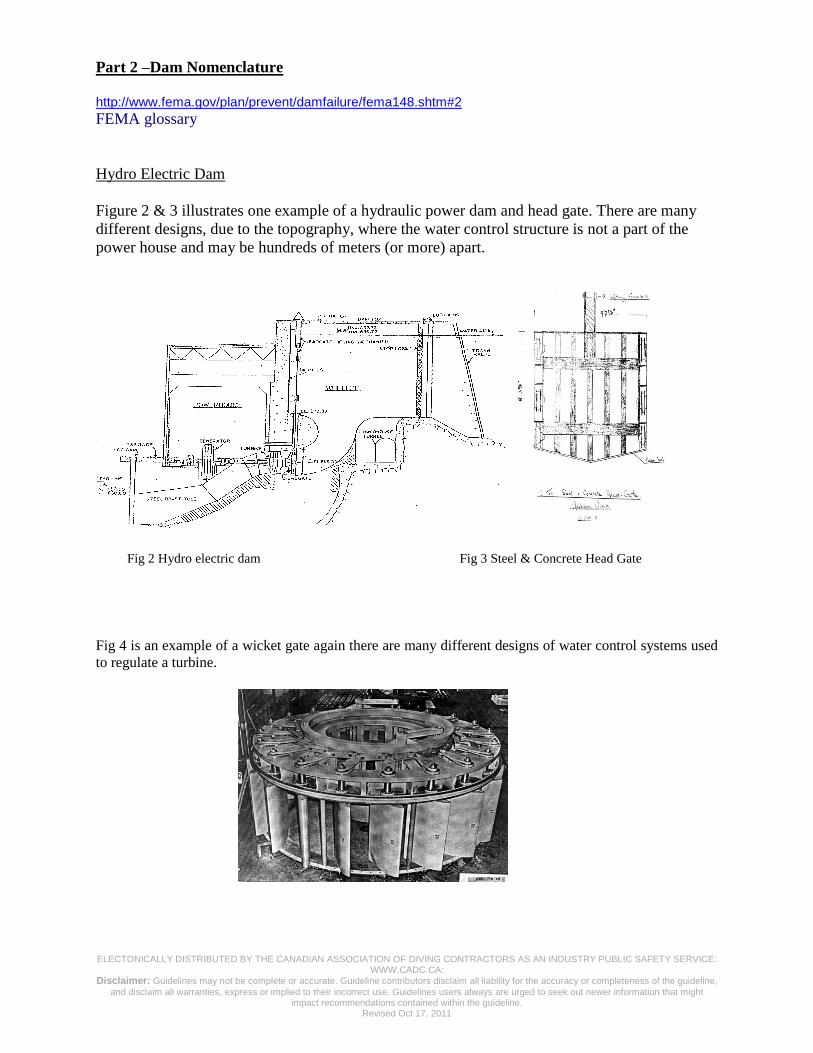
Part 2 –Dam Nomenclature
http://www.fema.gov/plan/prevent/damfailure/fema148.shtm#2 FEMA glossary
Hydro Electric Dam
Figure 2 & 3 illustrates one example of a hydraulic power dam and head gate. There are many
different designs, due to the topography, where the water control structure is not a part of the
power house and may be hundreds of meters (or more) apart.
Fig 2 Hydro electric dam Fig 3 Steel & Concrete Head Gate
Fig 4 is an example of a wicket gate again there are many different designs of water control systems used
to regulate a turbine.
ELECTONICALLY DISTRIBUTED BY THE CANADIAN ASSOCIATION OF DIVING CONTRACTORS AS AN INDUSTRY PUBLIC SAFETY SERVICE: WWW.CADC.CA:
Disclaimer: Guidelines may not be complete or accurate. Guideline contributors disclaim all liability for the accuracy or completeness of the guideline,
and disclaim all warranties, express or implied to their incorrect use. Guidelines users always are urged to seek out newer information that might impact recommendations contained within the guideline.
Revised Oct 17, 2011
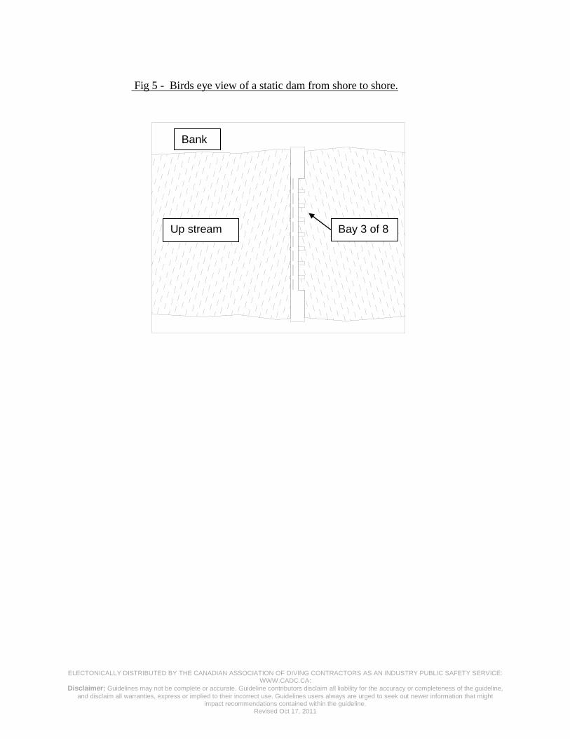
Fig 5 - Birds eye view of a static dam from shore to shore.
Up stream Bay 3 of 8
Bank

ELECTONICALLY DISTRIBUTED BY THE CANADIAN ASSOCIATION OF DIVING CONTRACTORS AS AN INDUSTRY PUBLIC SAFETY SERVICE: WWW.CADC.CA:
Disclaimer: Guidelines may not be complete or accurate. Guideline contributors disclaim all liability for the accuracy or completeness of the guideline,
and disclaim all warranties, express or implied to their incorrect use. Guidelines users always are urged to seek out newer information that might impact recommendations contained within the guideline.
Revised Oct 17, 2011
Figure 6 – Profile of a static dam
Part 2.1 – Methods in Detecting Delta P
2.1.1 Visual Signs
One indicator of a potential ΔP hazard is excessive water leakage from the downstream side of a
structure. If possible, examine the spillway, stop logs and structure for any visible or audible
signs of water leakage and the upstream side of the dam for any signs of suction (vortex), on the
surface, before conducting any other surveys. If excessive water leakage is evident then it is
imperative that the area around the source of the leakage is surveyed, on the upstream side of the
structure, in order to evaluate the severity of ΔP, its location and options to either control it or
avoid it. If additional tests indicate that the source of leakage cannot be controlled then the area
around it should be identified as a hazardous area and declared unsafe for diving.
Hydro Electric dams may not always offer good visual indicators because of the design of the
structure however downstream boils may be indicative of ground faults or leakage through the
structure.
2.1.2 Downstream Approaches
Diving on the downstream side of some types of dams, where turbulence does not pose a hazard
to the diver and safe access is available, is worth considering as a safe means of detecting
sources of hazardous water flow.
Down stream Apron
Sill
Spill way
Deck
Stop- Logs
Bull nose

ELECTONICALLY DISTRIBUTED BY THE CANADIAN ASSOCIATION OF DIVING CONTRACTORS AS AN INDUSTRY PUBLIC SAFETY SERVICE: WWW.CADC.CA:
Disclaimer: Guidelines may not be complete or accurate. Guideline contributors disclaim all liability for the accuracy or completeness of the guideline,
and disclaim all warranties, express or implied to their incorrect use. Guidelines users always are urged to seek out newer information that might impact recommendations contained within the guideline.
Revised Oct 17, 2011
2.1.3 Flow Indicator Devices
2.1.3 (i) Bag Test
A bag test involves the use of a sand bag that is loaded with enough material to make the bag just
heavy enough for the circumstances worked in (approximately 3-5lbs). It should be secured to a
3/8” rope that is long enough to reach the entire upstream portion of the structure where the diver
will be working plus a control area of at least 5m around the proposed work site. (Note – the
rope should not exceed 3/8” diameter because the diver’s feel might be affected it)
It can be a very effective means of detecting ΔP hazards if performed by a person who has had
the appropriate training and experience. It will also serve as an effective means of sealing off
some ΔP hazards and the rope, if tied off, will assist with the identifying the location of the
hazard.
In order to be effective, the bag must be lowered and raised slowly across the entire structure at
approximately 1 to 2 feet per second and as close as possible to the structure and river bed,
(within 10 inches). A vessel should be used to perform the bag test in situations where access to
the work site is difficult to reach from the deck of the structure.
A severe draw on the bag and rope or anytime where the bag is trapped and cannot be pulled free
are indicators of a serious ΔP hazard; the amount of force to pull the bag free of a ΔP hazard is
indicative of the water flow hazard.
Note* The person performing the bag test, must ensure that he is wearing gloves to protect
against rope burns and that all persons are free from being entangled by the rope in the case that
the bag is caught and pulled through a ΔP source. In addition, the person conducting the test
should also be protected by an adequate fall protection Any Significant hazard detected must
be effectively controlled before commencing a recognition dive.
Finally, although the bag is an effective means of detecting any existing ΔP hazards it must not
in itself be the sole indicator used to declare a site free from hazardous water flows. Its purpose
is only to determine if it is safe to commence a recognition dive.
2.1.3 (ii) Mop Test
A mop can be an effective tool to use during a recognition dive because its strands will react to
any water flow while the mop handle allows the diver to remain clear of any ΔP hazards. It may
be used to verify that ΔP does not exist at a structure that has not shown any indication of
hazardous water flow by a bag test. Nonetheless, it must only be used in good visibility and the
diver and diving umbilical must be provided with an independent restraint system until the
survey confirms the area is free from hazardous water flow hazards. (See - ΔP restraint system)
ELECTONICALLY DISTRIBUTED BY THE CANADIAN ASSOCIATION OF DIVING CONTRACTORS AS AN INDUSTRY PUBLIC SAFETY SERVICE: WWW.CADC.CA:
Disclaimer: Guidelines may not be complete or accurate. Guideline contributors disclaim all liability for the accuracy or completeness of the guideline,
and disclaim all warranties, express or implied to their incorrect use. Guidelines users always are urged to seek out newer information that might impact recommendations contained within the guideline.
Revised Oct 17, 2011
2.1.3 (iii) Pole & Ribbon Test
It is another means for performing the recognition dive as it allows the diver to remain clear of
any hazardous water flows. Nonetheless, it must only be used in circumstances where there is
good visibility and the diver and diving umbilical are restrained by an independent restraint
system until the survey is completed and the work site is declared safe from hazardous water
flows.
2.1.3 (iv) Pole Camera Survey
A pole camera combined with a surveyor’s ribbon is useful for detecting gaps and signs of a
hazardous water flow in relatively shallow water where there is good visibility. The ribbon is a
good indicator of hazardous water flow and may aid in preventing the loss of the camera
The person performing the survey with the pole camera must ensure that all persons are clear of
any entanglement with the pole camera system while it is being maneuvered around the
structure. In addition, the person performing the survey must use fall protection.
2.1.3 (vi) ROV Survey
In some circumstances a remote controlled vehicle is the only safe means of performing a survey
of a dam for potential ΔP hazards. Although potentially costly, if the ROV encounters ΔP, it is
certainly more preferable than a person being injured.
2.2 Recognition Dive
Its purpose is to establish a safety zone. This dive is performed in order to identify any signs
of a potential ∆P hazard, such as: structural damage, accumulation of debris, cracks, holes and gaps
\ after the successful completion of a bag test.
First it is essential that both the diver and diving supervisor review the drawings of the structure with
the Dam operator prior to the commencement of a “recognition dive” because of the necessity to
familiarize themselves with the structure its dimensions and any service pipes. (Note that drawings are
not always a true representation of what may exist, so caution is always recommended.)
Secondly the diver must use a ∆P travel restraint system as per clause 2.5.9 while performing a
recognition dive, and finally a rescue plan shall always be written and understood by all persons
participating in the diving operation.

ELECTONICALLY DISTRIBUTED BY THE CANADIAN ASSOCIATION OF DIVING CONTRACTORS AS AN INDUSTRY PUBLIC SAFETY SERVICE: WWW.CADC.CA:
Disclaimer: Guidelines may not be complete or accurate. Guideline contributors disclaim all liability for the accuracy or completeness of the guideline,
and disclaim all warranties, express or implied to their incorrect use. Guidelines users always are urged to seek out newer information that might impact recommendations contained within the guideline.
Revised Oct 17, 2011
2.3 Safety Zone
It is a work site that has been declared safe to dive in after the satisfactory completion of
a bag test and recognition dive. The boundaries of the safe zone may be identified by features such as
bull noses gates or with other indicators such as chain, rope etc. A 5 m buffer is the minimum
boundary when in open water.
Once the safety zone has been established there should be a restraint placed on the umbilical that
would prevent the diver from exiting the zone.
2.4 – Lock-Out Procedures
Specific lockout procedures will vary depending on the design of the system to be locked out, the
owner’s procedures and the water control authority that is responsible for the structures upstream
and downstream. In some cases dam operations may be controlled remotely, so clear
communications with the water control authority are vital.
For further guidance refer to the CSA Z460 Standard.
2.5 – Selection of Diving Equipment & Dive Site
2.5.1 Dive Site {vessel, dam deck or shoreline}
The location and adequacy of the dive site is critical in ensuring that appropriate surface support
is provided to a diver while diving at the upstream side of a dam – see clause 8.3.7 of the CSA
Z275.2-11 Standard.
The diver’s umbilical must be tended directly upstream of the diver and never permitted to enter
into any area not checked for delta P, as might be the case if diving from the shoreline or a dive
site located at another bay. This is for the reason that the diver’s umbilical may be captured by a
ΔP force and drag the diver into the hazard.
Note * It is crucial that the divers tender is knowledgeable in the techniques of managing a
divers umbilical, the importance of placing restraints on a divers umbilical and the effects of
current on a divers umbilical, at dive sites where a ΔP force may exist.
Another factor to consider when choosing a dive site, at the upstream side of a dam, is the ease
of access and egress. Clause 4.4.4 & 4.4.5 of the CSA Z275.2-11 Standard sets out requirements
for transportation through water surface and the recovery of an unconscious diver.
2.5.2 Surface Supplied Diving Apparatus
The use of Scuba at water control structures is prohibited, by Clause 7.1.3 of the CSA Z275.2 -
ELECTONICALLY DISTRIBUTED BY THE CANADIAN ASSOCIATION OF DIVING CONTRACTORS AS AN INDUSTRY PUBLIC SAFETY SERVICE: WWW.CADC.CA:
Disclaimer: Guidelines may not be complete or accurate. Guideline contributors disclaim all liability for the accuracy or completeness of the guideline,
and disclaim all warranties, express or implied to their incorrect use. Guidelines users always are urged to seek out newer information that might impact recommendations contained within the guideline.
Revised Oct 17, 2011
11 Standard.
2.5.3 Thermal Protection
Consideration shall be given to ensuring that the diver is wearing adequate thermal protection for
the environmental conditions that the diver is exposed to. This is for the reason that if trapped the
diver may die as a result of hypothermia before any rescue is possible.
2.5.4 Quantities of Divers Breathing Mixture
Clause 6.3.1.2 of the CSAZ275.2-11 Standard sets out requirements the general quantity of
available compressed air to complete the underwater tasks and for anticipated emergencies.
Factors such as, the remoteness of the dive site, the availability of additional compressed air off
site and the time to dewater or equalize a ΔP hazard (if possible) must be considered as an
anticipated emergency while diving at a water control structure.
2.5.5 Umbilical strength members
Clause 8.3.6 of the CSA Z275.2 -11 Standard requires an umbilical strength member to be rated
for a minimum breaking strength of at least 2,000 lbs. Nevertheless it should never be used as a
means to pull the diver free from a ΔP encounter because of the risk of transferring the load to
the diver’s air hose and helmet hose connection. (See Diver ΔP Restraint System)
2.5.6 Diver’s Harness
Clause 8.3.5 of the CSA Z275.2-11 Standard requires a diver’s harness to be a full body harness
rated at a minimum breaking strength of 2000lbs for normal diving operations.
Note: A harness with a higher breaking strength may be considered in unusual flow or possible
high flow situations.
2.5.7 Diver Communications
Clause 8.3.8 of the CSA Z275.2-11 Standard requires surface supplied divers to use effective
two way voice communications. (Round Robin system is preferred)
2.5. 8 TV & Lighting System
The addition of a helmet mounted underwater TV and lighting system is highly recommended
for diving operations at dams because it gives the diving supervisor an opportunity to identify
any underwater hazards that the diver may not have recognized. It is also provides another means
to get the divers attention in the event of communications failure by flashing the light.
2.5.9 Divers ΔP Restraint System

ELECTONICALLY DISTRIBUTED BY THE CANADIAN ASSOCIATION OF DIVING CONTRACTORS AS AN INDUSTRY PUBLIC SAFETY SERVICE: WWW.CADC.CA:
Disclaimer: Guidelines may not be complete or accurate. Guideline contributors disclaim all liability for the accuracy or completeness of the guideline,
and disclaim all warranties, express or implied to their incorrect use. Guidelines users always are urged to seek out newer information that might impact recommendations contained within the guideline.
Revised Oct 17, 2011
The diver must use a travel restraint system (a separate safety line rated at 5000lbs) while
performing a recognition dive because it will assist as a means to resist encounters with a
hazardous water flow during descent, time at the bottom and ascent. The system should be
designed only as a means to quickly pull the diver and his umbilical clear of any hazardous water
flow encountered without compromising the divers air supply.
A separate diver safety line (rated for at least 5000lbs) that is connected to a winch on the surface
and fairlead through a clump weight or other substantial rigging system, on the river bed
upstream of the work site, is one example of an effective travel restraint system.
Part 2.6 - Rescue Options
2.6.1 Reduction of ΔP
In the event that a diver is trapped by a ΔP force it is unlikely that he will be pulled free, without
suffering additional trauma, until the force has been equalized or reduced significantly.
Therefore, serious consideration must be given as to how much pressure may be applied without
causing serious trauma to a trapped diver. Keep in mind that it is not always possible to reduce
the pressure and in those cases prevention is vital because the diver’s chances of survival are
slim.
Where it is possible to equalize a ΔP force there must be adequate personnel available to operate
the equipment necessary for dewatering the work site in a timely manner. In addition, the diver’s
umbilical should be tended by no more than two persons unless it is necessary to prevent an
entrapped diver from being pulled further into a hole or gap.
If the diver is not connected to a travel restraint system then consideration should be given to
rigging one to the diver providing that every precaution is taken to protect the standby diver from
any hazardous water flow. (A bag test must be performed to verify that the area around the
trapped diver is free from sources of ΔP hazards.) Efforts to pull the diver from different angles
with the safety line should be attempted during the dewatering phase)
The water control authority is responsible for coordinating the flows of the dams upstream and
downstream of the structure where the diver is trapped and every effort should be made to lower
or equalize the pressure wherever possible.
2.6.2 Air Injection
The injection of bursts of large volumes of air between an object and source of ΔP, in a lab
setting, has shown some positive results. However there is no record of it being used in the field
to rescue a diver and the volume of air required far exceeds the capacity of the compressors used
to supply the diver’s breathing air.
ELECTONICALLY DISTRIBUTED BY THE CANADIAN ASSOCIATION OF DIVING CONTRACTORS AS AN INDUSTRY PUBLIC SAFETY SERVICE: WWW.CADC.CA:
Disclaimer: Guidelines may not be complete or accurate. Guideline contributors disclaim all liability for the accuracy or completeness of the guideline,
and disclaim all warranties, express or implied to their incorrect use. Guidelines users always are urged to seek out newer information that might impact recommendations contained within the guideline.
Revised Oct 17, 2011
Part 3 – Water Intakes
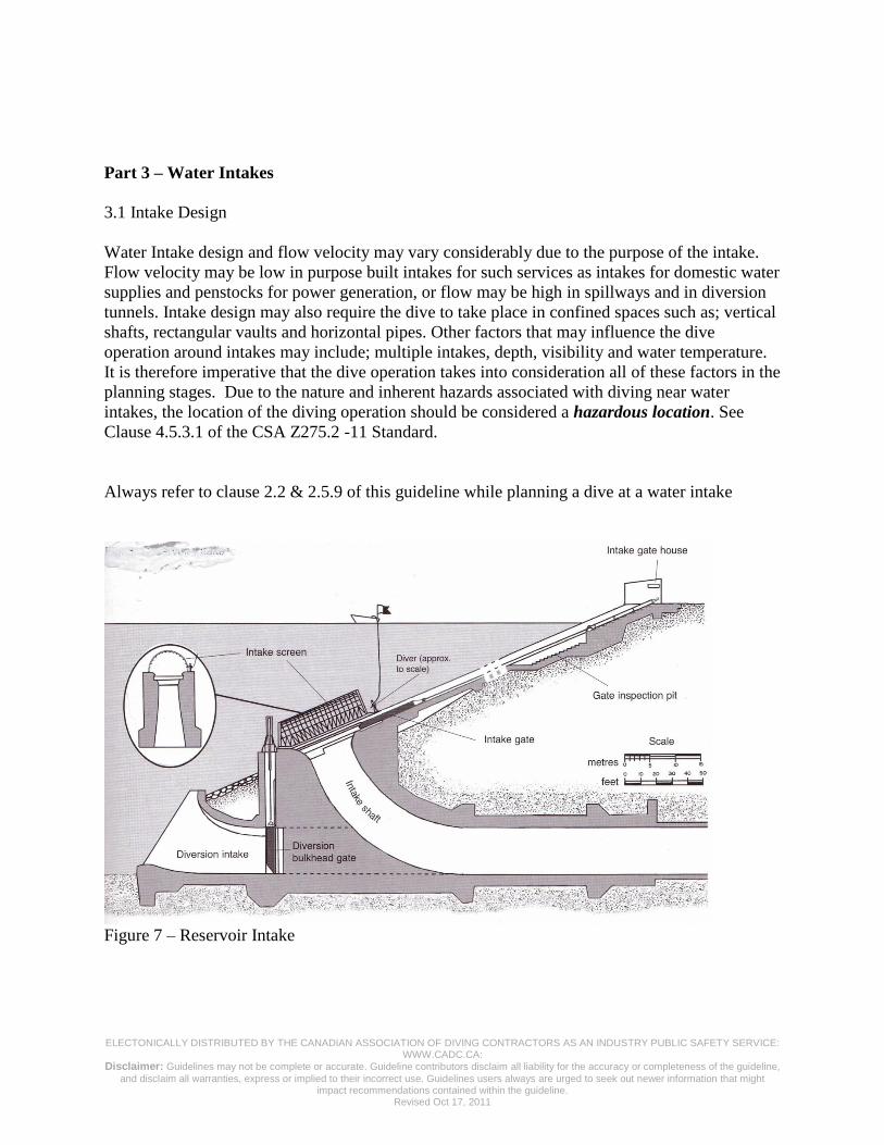
3.1 Intake Design
Water Intake design and flow velocity may vary considerably due to the purpose of the intake.
Flow velocity may be low in purpose built intakes for such services as intakes for domestic water
supplies and penstocks for power generation, or flow may be high in spillways and in diversion
tunnels. Intake design may also require the dive to take place in confined spaces such as; vertical
shafts, rectangular vaults and horizontal pipes. Other factors that may influence the dive
operation around intakes may include; multiple intakes, depth, visibility and water temperature.
It is therefore imperative that the dive operation takes into consideration all of these factors in the
planning stages. Due to the nature and inherent hazards associated with diving near water
intakes, the location of the diving operation should be considered a hazardous location. See
Clause 4.5.3.1 of the CSA Z275.2 -11 Standard.
Always refer to clause 2.2 & 2.5.9 of this guideline while planning a dive at a water intake
Figure 7 – Reservoir Intake

ELECTONICALLY DISTRIBUTED BY THE CANADIAN ASSOCIATION OF DIVING CONTRACTORS AS AN INDUSTRY PUBLIC SAFETY SERVICE: WWW.CADC.CA:
Disclaimer: Guidelines may not be complete or accurate. Guideline contributors disclaim all liability for the accuracy or completeness of the guideline,
and disclaim all warranties, express or implied to their incorrect use. Guidelines users always are urged to seek out newer information that might impact recommendations contained within the guideline.
Revised Oct 17, 2011
Figure 8 – Draw-off Tower
3.2 Screens
On most intakes a water intake protection system will be installed. There are a number of
different types of protective systems used to prevent debris from being drawn into the intake. It
is not uncommon for divers to be employed to clean or repair these devices. Listed below are a
number of common systems currently used;
Log booms
Are installed on the surface of the water to prevent floating debris from accumulating near the
intake.
Fixed Screens
Commonly referred to as “trash racks”, the screens are made up of a number of steel bars or flat
stock fabricated to provide a fixed screen over the entrance to the intake to prevent debris from
being drawn into the intake.
Traveling Water Screens (TWS)
Traveling water screens are commonly used by power generation companies to protect the
intakes. The design of these screens allow for debris to be removed from the screens on a
regular automated schedule therefore allowing greater time between manual cleaning of the
screens.

ELECTONICALLY DISTRIBUTED BY THE CANADIAN ASSOCIATION OF DIVING CONTRACTORS AS AN INDUSTRY PUBLIC SAFETY SERVICE: WWW.CADC.CA:
Disclaimer: Guidelines may not be complete or accurate. Guideline contributors disclaim all liability for the accuracy or completeness of the guideline,
and disclaim all warranties, express or implied to their incorrect use. Guidelines users always are urged to seek out newer information that might impact recommendations contained within the guideline.
Revised Oct 17, 2011
Traveling Water Screens (TWS) Safety
When diving on TWS systems, the diver must take caution to ensure that:
The screen controls are locked-out so that the screen will not start while the diver is in
the water.
Never enter a damaged screen if there is a possibility of a start up.
Practice good umbilical management, entanglement is of particular concern when
working on the TWS.
Caution should be exercised to prevent hands, feet and extraneous gear from being
trapped in machinery if an unexpected start up occurs.
Environmentally Safe Screens
These screens are designed to allow a high flow of water through a large surface area while not
impinging on small marine life. Due to the design of these systems the small opening tend to get
clogged up and are cleaned by built in high pressure cleaning system, that does not required the
use of divers. If maintenance or repairs are required on these systems, divers should be aware of
the following precautions;
Ensure the pump is locked-out
Ensure flow to the screen has being locked out or controlled to the satisfaction of the
diver and diving supervisor
3.3 Water Flow
Ensure that all pumps and valves are locked-out in manner that is acceptable to the diver and
diving supervisor. Establish that there is no flow in the intake that the diver will be working near.
If the flow is unable to be stopped, ensure it is controlled, in a positive manner, to a rate
acceptable to protect the health and safety of the diver, and satisfactory to the diving supervisor
and the regulating authority. Clause 4.5.3.4 of the Z275.2-04 Standard.
For further guidance, refer to Part 2.1, sections 2.1.1 to 2.1.3.
3.4 Intake identification
In the event two or more intakes, pipes or ducts are in the same area as the diver, a method will
be in place for the diver to accurately and positively identify the intake, pipe or duct he/she is to
work on. Clause 4.5.3.3 of the Z275.2-11 Standard.
Caution is to be taken to ensure that other intakes may be in the same area and not identified as
part of the same system and therefore may not be identified on site plans, blue prints, etc. i.e.;
System 1 - Domestic water supply, system 2 – Fire suppression
ELECTONICALLY DISTRIBUTED BY THE CANADIAN ASSOCIATION OF DIVING CONTRACTORS AS AN INDUSTRY PUBLIC SAFETY SERVICE: WWW.CADC.CA:
Disclaimer: Guidelines may not be complete or accurate. Guideline contributors disclaim all liability for the accuracy or completeness of the guideline,
and disclaim all warranties, express or implied to their incorrect use. Guidelines users always are urged to seek out newer information that might impact recommendations contained within the guideline.
Revised Oct 17, 2011
3.5 Dive Equipment
Surface supplied diving equipment, c/w voice communications will be used on all dives in
hazardous areas as identified in clause 4.5.3.1 and as required in clause 4.5.2 of the CSA Z275.2
-11 Standard.
The use of SCUBA is prohibited when diving operations are carried out near underwater intakes,
by Clause 7.1.4 of the CSA Z275.2 -11 Standard.
3.6 Penetration Diving
It may be necessary to enter confined spaces such as pipes, ducts and other structures to perform
work in and around intakes. If these dives are to take place additional precautions must be taken
to ensure the health and safety of the diver.
For further guidance, please refer to; Guidelines for Penetration Diving found in Appendix J of
the Z275.2-11 Standard.
Part-4 Delta –P hazards working with Pipelines
4.1 Pipeline flooding and pigging operations
Pigging operations and pipeline tie-ins pose a considerable risk to divers if adequate precautions
are not put in place to identify Delta-P hazards.
Pipelines are normally deployed in a dry state with a blind flange and some form of double block
and bleed, or ball valve assembly to flood the pipe.
Divers have been seriously injured opening valves, or trying to remove blind flanges without
verifying equalization in pressure on both sides of the flange.
Never assume a pipe is fully flooded, always approach flanges with caution.
Use a removable diffuser or “T” section of pipe on the end of a flood valve to prevent
body parts from making a seal on the opening.
When checking for flow around valves never use your hand, use a frayed piece of rope on
a pole or other sacrificial device.
If available, use an ROV to perform an initial survey before sending the diver in.
Never stand directly in front of a flood valve when opening, always stand behind or to the
side and open valves slowly.
Never use a Ship’s buoy or other inflatable device inside a pipe when a diver is in the
water. Rapid temperature and pressure changes upon submersion can cause buoys to fail
suddenly causing a rapid uncontrolled flooding and equalization.

ELECTONICALLY DISTRIBUTED BY THE CANADIAN ASSOCIATION OF DIVING CONTRACTORS AS AN INDUSTRY PUBLIC SAFETY SERVICE: WWW.CADC.CA:
Disclaimer: Guidelines may not be complete or accurate. Guideline contributors disclaim all liability for the accuracy or completeness of the guideline,
and disclaim all warranties, express or implied to their incorrect use. Guidelines users always are urged to seek out newer information that might impact recommendations contained within the guideline.
Revised Oct 17, 2011
4.2 Protection Flanges used for deployment of Spool pieces and Flexible Hoses
Smaller rigid sections of pipe and flexible hoses are often deployed or “wet stored” sub sea for
divers to tie in to existing pipelines and manifolds.
Sealing faces are often protected with a sacrificial plywood face when deployed over the side to
the divers. Serious injuries and fatalities have occurred to divers attempting to remove the
wooden flanges with small differential pressures behind the flange.
Always ensure wooden protection flanges have several large holes each end to ensure
adequate flooding of the pipe.
Avoid rapid submersion of pipe sections to allow for flooding before it reaches the
diver(s).
Never try to pry open a wooden flange or “punch” a hole to attempt flooding. Recover
the section to surface if possible and drill an adequate equalization hole.
Fig 9 - Example of Diffuser Fig 10 - Example of a wood flange
protection cover that may
pose a serious hazard to a
diver, because there is no
centre hole to equalize
pressure differential.

ELECTONICALLY DISTRIBUTED BY THE CANADIAN ASSOCIATION OF DIVING CONTRACTORS AS AN INDUSTRY PUBLIC SAFETY SERVICE: WWW.CADC.CA:
Disclaimer: Guidelines may not be complete or accurate. Guideline contributors disclaim all liability for the accuracy or completeness of the guideline,
and disclaim all warranties, express or implied to their incorrect use. Guidelines users always are urged to seek out newer information that might impact recommendations contained within the guideline.
Revised Oct 17, 2011
Part 5 – Water Towers/Reservoirs
Part 5.1 – Methods in detecting Delta P forces at dams see: 2.1.3 Flow indicator
Devices:
(ii) Mop test
(iii) Pole & Ribbon Test
(iv) ROV surveys
Part 5.2 – Engineering Controls & Calculations
The flow rates on in Water Towers/Reservoirs fluctuate according to the demand on the system
and cause an exceptional ΔP hazard without notice. In most cases this water supply cannot be
locked out because of public safety issues such as, fire fighting services. For this reason an
effective means to protect a diver from a ΔP hazard at the standpipe must be designed and
installed (if not already provided) before a recognition dive is performed.
An engineered diffuser that fits over the standpipe on inlet may be one example of an effective
engineering control.
Example of calculating excursion umbilical lengths.
a = depth of water
b = distance to nearest hazard from tied-off tending point.
c = maximum length of excursion umbilical to be let out by tender
Note 1: umbilical to be secured at surface.
Note 2: Maximum length of umbilical usually 2-3 meters less than “c” to eliminate contact with
hazard. This is an example only, depending on risk assessment and company operating
procedures.
E.g.: Water depth: “a” 10m
Distance to nearest hazard: “b” 25m
Calculate maximum amount of excursion umbilical. “c” ?
a2 +b2 = c2
(10x10) + (25x25) = c2
100 + 625 = 725 725 (square root) = 26.9m
minus 3 meters of umbilical, c= 23.9 m

ELECTONICALLY DISTRIBUTED BY THE CANADIAN ASSOCIATION OF DIVING CONTRACTORS AS AN INDUSTRY PUBLIC SAFETY SERVICE: WWW.CADC.CA:
Disclaimer: Guidelines may not be complete or accurate. Guideline contributors disclaim all liability for the accuracy or completeness of the guideline,
and disclaim all warranties, express or implied to their incorrect use. Guidelines users always are urged to seek out newer information that might impact recommendations contained within the guideline.
Revised Oct 17, 2011
The maximum amount of umbilical to let out by the tender is 23.9m
5.3 Recognition Dive
Its purpose is to establish a safety zone. The dive is to identify any signs of a potential ΔP
hazard, such as: structural damage, accumulation of debris, cracks after the successful
completion of a flow indicator test.
First, it is essential that both the diver and diving supervisor review the drawings of the Water
Towers/Reservoirs prior to the commencement of a “recognition dive” because of the necessity
to familiarize themselves with the structure its dimensions and any service pipes.
(Note that drawings are not always a true representation of what may exist, so caution is always
recommended.)
Part 5.4 Safety Zone
A work site has been declared safe to dive in after the satisfactory Lock-Out 5.4, and completion
of a flow indicating test and recognition dive.
5.4.1 Confined Space considerations
Before a worker is required or permitted to enter a confined space, the employer must meet the

ELECTONICALLY DISTRIBUTED BY THE CANADIAN ASSOCIATION OF DIVING CONTRACTORS AS AN INDUSTRY PUBLIC SAFETY SERVICE: WWW.CADC.CA:
Disclaimer: Guidelines may not be complete or accurate. Guideline contributors disclaim all liability for the accuracy or completeness of the guideline,
and disclaim all warranties, express or implied to their incorrect use. Guidelines users always are urged to seek out newer information that might impact recommendations contained within the guideline.
Revised Oct 17, 2011
requirements of the authority having jurisdiction.
5.4.2 Guard Rails / Fall Restraint
An employer must ensure that a fall protection system is used when work is being done at an
elevated place is conducted to the requirements of the authority having jurisdiction.
Temporary removal of guardrails If a guardrail must be removed to accommodate work,
(a) Only that portion of the guardrail necessary to allow the work to be done
may be removed, and
(b) Workers exposed to a fall hazard must be protected by another fall
protection system when the guardrail is absent.
The guardrail must be replaced
(a) When the unguarded area is left unattended, and
(b) After the work is completed if the circumstances still require guardrails.
5.4.3 Equipment
All safety equipment used in this type of diving must take in to consideration not only diving but
as well the possibility of working:
in confined spaces, and
at elevated heights.
Note * It is recommended that the dive contractor contact the authority having jurisdiction to
establish these requirements.
Part 5.5 – Lock-Out Procedures
Specific lockout procedures will vary depending on the design of the system to be locked out, the
owner’s procedures and the water control authority that is responsible for the structures.
For further guidance refer to the CSA Z460 Standard.
Part 5.5 – Selection of Diving Equipment & Dive Site
See 2.5 Selection of Diving Equipment & Dive Site
Part 5.6 - Rescue Options - See 2.6

ELECTONICALLY DISTRIBUTED BY THE CANADIAN ASSOCIATION OF DIVING CONTRACTORS AS AN INDUSTRY PUBLIC SAFETY SERVICE: WWW.CADC.CA:
Disclaimer: Guidelines may not be complete or accurate. Guideline contributors disclaim all liability for the accuracy or completeness of the guideline,
and disclaim all warranties, express or implied to their incorrect use. Guidelines users always are urged to seek out newer information that might impact recommendations contained within the guideline.
Revised Oct 17, 2011
Part 6 – Ship Intakes – Sea Chests – Propellers - Impellers - Thrusters
6.1 Risk Assessment
6.1.1 Identify Delta P Hazard(s)
Diving contractors must conduct a pre-dive risk assessment to identify known and
potential Delta P hazards using appropriate methods of detection. Delta P risks
should be presumed to exist in any diving environment where;
Water levels between adjoining areas vary;
Water is juxtaposed against gaseous voids;
Water is mechanically drawn through intakes and
Water is mechanically drawn toward propulsors, impellers, or other types
of thrusters on ships.
Risk assessment methods are closely aligned with proper action by the vessel’s
engineering department in notifying the diving contractor of active intake pumps,
engaged hydraulics (rudders, variable-pitch propellers), and in some instances
cathodic protection. Coordination and verification by the ship’s engineering
department and diving contractor of tag outs and lock outs should follow the
initial planning of the operation.
Visual inspections of the work area should only be performed by experienced
divers selected by the diving supervisor. Divers conducting the visual inspection
can use either the mop, or pole and ribbon test to identify Delta P hazards, when
using an independent restraint system and only when the diver has good visibility.
6.1.2 Calculate potential Delta P factors
Where Delta P is known to exist, the pressure differential across an opening (or
potential opening) through a bulkhead separating bodies of water with different
surface levels, or separating a gas filled space at atmospheric pressure from a
body of water can be determined by the following formula:
P = D x PC
Where:
P = Pressure differential across opening
D = Depth of water above opening (or difference in water depth on the
two sides of a potential opening
PC = Pressure change per unit increase in depth
The total force (actual or potential) exerted by the pressure differential across an
opening is calculated by multiplying the pressure differential by the area of the
opening:
F = P x A = D x PC x A
Where:
F = Force in customary units
A = Area in units compatible with units of force

ELECTONICALLY DISTRIBUTED BY THE CANADIAN ASSOCIATION OF DIVING CONTRACTORS AS AN INDUSTRY PUBLIC SAFETY SERVICE: WWW.CADC.CA:
Disclaimer: Guidelines may not be complete or accurate. Guideline contributors disclaim all liability for the accuracy or completeness of the guideline,
and disclaim all warranties, express or implied to their incorrect use. Guidelines users always are urged to seek out newer information that might impact recommendations contained within the guideline.
Revised Oct 17, 2011
Table 6.1 provides the appropriate constant, Pc for different units of force, depth,
and area.
Table 6.1 Constants for use in Calculating Force due to Delta P
F = D x A x Pc
If Force is
desired in:
and Depth is
given in:
and Area is measured
in:
Then use the values below
for Pc
for
Fresh Water:
for
Sea Water:
pounds (lb) feet (ft) square inches (in2) 0.433 0.445
pounds (lb) feet (ft) square feet (ft2) 62.4 64
Newtons (N) meters (m) square meters (m2) 9807 10052
Newtons (N) meters (m) square centimeters
(cm2)
0.9807 1.0052
Kilonewtons
(KN)
meters (m) square meters (m2) 9.807 10.052
Kilograms (Kg) meters (m) square meters (m2) 1000 1025
Kilograms (Kg) meters (m) square centimeters
(cm2)
0.1000 0.1025
For operations in brackish water, the values for seawater should be used to
calculate Delta P force, unless the pressure increase per foot of water depth can be
determined accurately. In waters subject to tidal fluctuations, where the salinity
may vary , the values for seawater should be used to calculate the worst case
condition.
Delta P hazards near intakes supplying pumps result from potentially high water
flow velocities (discussed below), and, if the intake is completely obstructed by a
divers body, the maximum suction that could be exerted by the running pump.
This suction would be in addition to the pressure head of the water above the
intake, at least until the pump stalls or is secured. The suction could persist even
after the pump is secured if water cannot be fed into the suction piping to re-
pressurize it.
All pumps are rated with a maximum suction head, normally expressed as the
height above water level, in feet or meters, that the pump can draw water for
subsequent discharge. This is normally referred to as negative suction head.
Typical centrifugal and axial flow pumps can function with suction heads of up to
10 feet, although some can operate against suction heads of up to 20 feet.
Reciprocating pumps and other types of positive displacement pumps can
generate suctions approaching complete vacuum – suction heads for positive
displacement pumps are often in the 25 to 29 foot range.
If the suction head, in feet or meters, for the pump is known, the suction force
generated if the intake is completely obstructed can be calculated by the formulas
given above for calculating delta P force across an opening in a bulkhead. If

ELECTONICALLY DISTRIBUTED BY THE CANADIAN ASSOCIATION OF DIVING CONTRACTORS AS AN INDUSTRY PUBLIC SAFETY SERVICE: WWW.CADC.CA:
Disclaimer: Guidelines may not be complete or accurate. Guideline contributors disclaim all liability for the accuracy or completeness of the guideline,
and disclaim all warranties, express or implied to their incorrect use. Guidelines users always are urged to seek out newer information that might impact recommendations contained within the guideline.
Revised Oct 17, 2011
suction head is expressed in pressure units, such as psi or Pa, then potential
suction force is calculated by multiplying the area of the intake opening by the
pressure.
Once the pump intake is obstructed, the suction generated by the pump is in
addition to force exerted by the water depth above the intake.
Pumps installed below water level (such as in ship’s machinery spaces, dams, or
similar structures) may be designed to operate only with positive suction head –
that is, the pump would be incapable of lifting water from a lower level. For such
pumps, it should be assumed that if the intake is completely blocked, the pump
can lower pressure in the intake piping to atmospheric. This means that the delta
P at the intake, and the resulting force, will be due only to the height of water
above the intake, as calculated by the formulas given above.
Water flow rate at the intake serving a pump can be taken as equal to the pumps
maximum discharge rate – although the pump may sometimes operate at less than
full capacity, the maximum rate represents the worst case scenario. Flow rate
through an opening in a bulkhead can be determined using the formula:
Q = A x v = A x 2gH
Where:
Q = Flow rate
A = Area of opening
v = Velocity of water flow
g = acceleration due to gravity
H = Depth of water above an opening to a gas filled space, or
= Difference between water level on two sides of a bulkhead.
The flow formula can be re-written as:
Q = C x A x H
Where:
C = Constant taken from Table 6.2; numerically equal to the
product of 2g and any necessary conversion factors,
appropriate to the units specified for Q, A, and H
Q = Flow rate in specified units
A = Area of opening in specified units
H = Depth of water above the opening in specified units
Table 6.2 Constants for use in Calculating Flow Through an Opening due to Delta P
Q = Constant x A x √H
If flow Q is desired in: and depth H is
given in:
and Area is measured
in:
Then use the value
below for the Constant
cubic meters per second
(m3/s)
meters (m) square meters (m2) 4.43
cubic meters per second
(m3/s)
meters (m) square centimeters
(cm2)
0.000443
cubic feet per second
(ft3/s)
feet (ft) square feet (ft2) 8.02

ELECTONICALLY DISTRIBUTED BY THE CANADIAN ASSOCIATION OF DIVING CONTRACTORS AS AN INDUSTRY PUBLIC SAFETY SERVICE: WWW.CADC.CA:
Disclaimer: Guidelines may not be complete or accurate. Guideline contributors disclaim all liability for the accuracy or completeness of the guideline,
and disclaim all warranties, express or implied to their incorrect use. Guidelines users always are urged to seek out newer information that might impact recommendations contained within the guideline.
Revised Oct 17, 2011
cubic feet per second
(ft3/s)
feet (ft) square inches (in2) 0.056
gallons per minute (gpm) feet (ft) square feet (ft2) 3600
gallons per minute (gpm) feet (ft) square inches (in2) 25
Example: Flow rate through a 6 inch diameter circular opening 10 feet below the
surface could be calculated by the following:
A = x r2 r = 3 in = 3/12 = 0.25 ft
= 3.1416 x 0.252
= 0.19635 ft2
Q = 3600 x A x H
= 3600 x 0.19635 x 10
= 2235.3 gpm
Example: Flow rate through a 16 cm diameter circular opening 3 meters below
the surface would be calculated by:
A = x r2 r = 8 cm = 8/100 = 0.08 m
= 3.1416 x 0.082
= 0.0201 m2
Q = 4.43 x A x H
= 4.43 x 0.0201 x 3
= 0.154 m3/sec
Note: 16 cm is slightly more than 6 inches, and 3 meters is about 9.8 feet. 0.154
m3/sec is 154 liters per second or 9240 liters per minute. Since one gallon is 3.79
liters, the flow rate through this opening is about 2338 gpm, which is comparable
to that through a 6 inch opening at a similar depth.
Differential pressure hazard boundaries can be established by determining the
safe flow rate area surrounding the hazard. Divers should avoid areas where the
flow velocity exceeds 0.5 meters/sec. (1.64 feet/sec) (.967 knots).
Flow velocity is equal to the flow rate divided by the flow area (v = Q/A). Flow
velocity at any distance from the opening can be estimated by assuming that flow
coming in towards the comes from all available directions, and that at any
distance (radius) the complete flow is evenly distributed over a hemispherical
surface with that radius. The surface area of a sphere is 4R2; that of a
hemisphere is thus 2R2. Velocity can thus be calculated:
v = Q/(2R2)
Setting the velocity equal to the maximum acceptable value (0.5 m/sec), the
formula can be transposed to calculate the distance where water is moving at that
velocity (stand-off distance):
v = 0.5 m/sec = Q/(2 x x R2)
R2 = Q/(2 x x 0.5) = Q/
R = (Q/)
Where:
Q = Flow rate, m3/sec
R = Stand-off distance, m (distance where V drops to 0.5 m/sec)
ELECTONICALLY DISTRIBUTED BY THE CANADIAN ASSOCIATION OF DIVING CONTRACTORS AS AN INDUSTRY PUBLIC SAFETY SERVICE: WWW.CADC.CA:
Disclaimer: Guidelines may not be complete or accurate. Guideline contributors disclaim all liability for the accuracy or completeness of the guideline,
and disclaim all warranties, express or implied to their incorrect use. Guidelines users always are urged to seek out newer information that might impact recommendations contained within the guideline.
Revised Oct 17, 2011
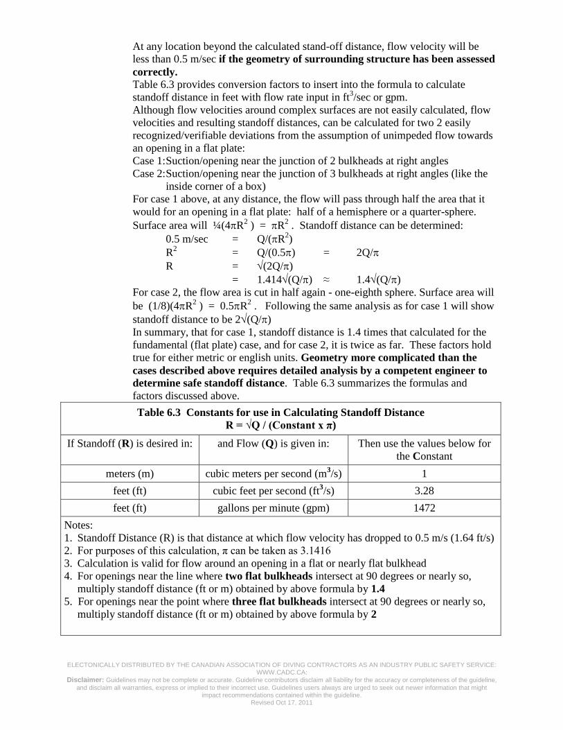
At any location beyond the calculated stand-off distance, flow velocity will be
less than 0.5 m/sec if the geometry of surrounding structure has been assessed
correctly. Table 6.3 provides conversion factors to insert into the formula to calculate
standoff distance in feet with flow rate input in ft3/sec or gpm.
Although flow velocities around complex surfaces are not easily calculated, flow
velocities and resulting standoff distances, can be calculated for two 2 easily
recognized/verifiable deviations from the assumption of unimpeded flow towards
an opening in a flat plate:
Case 1: Suction/opening near the junction of 2 bulkheads at right angles
Case 2: Suction/opening near the junction of 3 bulkheads at right angles (like the
inside corner of a box)
For case 1 above, at any distance, the flow will pass through half the area that it
would for an opening in a flat plate: half of a hemisphere or a quarter-sphere.
Surface area will ¼(4R2 ) = R
2 . Standoff distance can be determined:
0.5 m/sec = Q/(R2)
R2 = Q/(0.5) = 2Q/
R = (2Q/)
= 1.414(Q/) ≈ 1.4(Q/)
For case 2, the flow area is cut in half again - one-eighth sphere. Surface area will
be (1/8)(4R2 ) = 0.5R
2 . Following the same analysis as for case 1 will show
standoff distance to be 2(Q/)
In summary, that for case 1, standoff distance is 1.4 times that calculated for the
fundamental (flat plate) case, and for case 2, it is twice as far. These factors hold
true for either metric or english units. Geometry more complicated than the
cases described above requires detailed analysis by a competent engineer to
determine safe standoff distance. Table 6.3 summarizes the formulas and
factors discussed above.
Table 6.3 Constants for use in Calculating Standoff Distance
R = √Q / (Constant x π)
If Standoff (R) is desired in: and Flow (Q) is given in: Then use the values below for
the Constant
meters (m) cubic meters per second (m3/s) 1
feet (ft) cubic feet per second (ft3/s) 3.28
feet (ft) gallons per minute (gpm) 1472
Notes:
1. Standoff Distance (R) is that distance at which flow velocity has dropped to 0.5 m/s (1.64 ft/s)
2. For purposes of this calculation, π can be taken as 3.1416
3. Calculation is valid for flow around an opening in a flat or nearly flat bulkhead
4. For openings near the line where two flat bulkheads intersect at 90 degrees or nearly so,
multiply standoff distance (ft or m) obtained by above formula by 1.4
5. For openings near the point where three flat bulkheads intersect at 90 degrees or nearly so,
multiply standoff distance (ft or m) obtained by above formula by 2
ELECTONICALLY DISTRIBUTED BY THE CANADIAN ASSOCIATION OF DIVING CONTRACTORS AS AN INDUSTRY PUBLIC SAFETY SERVICE: WWW.CADC.CA:
Disclaimer: Guidelines may not be complete or accurate. Guideline contributors disclaim all liability for the accuracy or completeness of the guideline,
and disclaim all warranties, express or implied to their incorrect use. Guidelines users always are urged to seek out newer information that might impact recommendations contained within the guideline.
Revised Oct 17, 2011
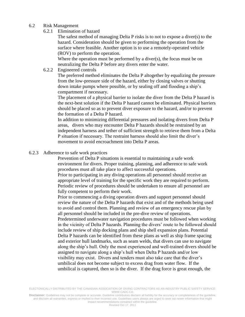
6.2 Risk Management
6.2.1 Elimination of hazard
The safest method of managing Delta P risks is to not to expose a diver(s) to the
hazard. Consideration should be given to performing the operation from the
surface where feasible. Another option is to use a remotely-operated vehicle
(ROV) to perform the operation.
Where the operation must be performed by a diver(s), the focus must be on
neutralizing the Delta P before any divers enter the water.
6.2.2 Engineered controls
The preferred method eliminates the Delta P altogether by equalizing the pressure
from the low-pressure side of the hazard, either by closing valves or shutting
down intake pumps where possible, or by sealing off and flooding a ship’s
compartment if necessary.
The placement of a physical barrier to isolate the diver from the Delta P hazard is
the next-best solution if the Delta P hazard cannot be eliminated. Physical barriers
should be placed so as to prevent diver exposure to the hazard, and/or to prevent
the formation of a Delta P hazard.
In addition to minimizing differential pressures and isolating divers from Delta P
areas, divers who may encounter Delta P hazards should be restrained by an
independent harness and tether of sufficient strength to retrieve them from a Delta
P situation if necessary. The restraint harness should also limit the diver’s
movement to avoid encroachment into Delta P areas.
6.2.3 Adherence to safe work practices
Prevention of Delta P situations is essential to maintaining a safe work
environment for divers. Proper training, planning, and adherence to safe work
procedures must all take place to affect successful operations.
Prior to participating in any diving operations all personnel should receive an
appropriate level of training for the specific work they are required to perform.
Periodic review of procedures should be undertaken to ensure all personnel are
fully competent to perform their work.
Prior to commencing a diving operation divers and support personnel should
review the nature of the Delta P hazards that exist and of the methods being used
to avoid and control them. Planning and review of an emergency rescue plan by
all personnel should be included in the pre-dive review of operations.
Predetermined underwater navigation procedures must be followed when working
in the vicinity of Delta P hazards. Planning the divers’ route to be followed should
include review of ship docking plans and ship shell expansion plans. Potential
Delta P hazards can be identified from these plans as well as ship frame spacing
and exterior hull landmarks, such as seam welds, that divers can use to navigate
along the ship’s hull. Only the most experienced and well-trained divers should be
assigned to navigate along a ship’s hull when Delta P hazards and/or low
visibility may exist. Divers and tenders must also take care that the diver’s
umbilical does not become subject to excess drag from water flow. If the
umbilical is captured, then so is the diver. If the drag force is great enough, the
ELECTONICALLY DISTRIBUTED BY THE CANADIAN ASSOCIATION OF DIVING CONTRACTORS AS AN INDUSTRY PUBLIC SAFETY SERVICE: WWW.CADC.CA:
Disclaimer: Guidelines may not be complete or accurate. Guideline contributors disclaim all liability for the accuracy or completeness of the guideline,
and disclaim all warranties, express or implied to their incorrect use. Guidelines users always are urged to seek out newer information that might impact recommendations contained within the guideline.
Revised Oct 17, 2011
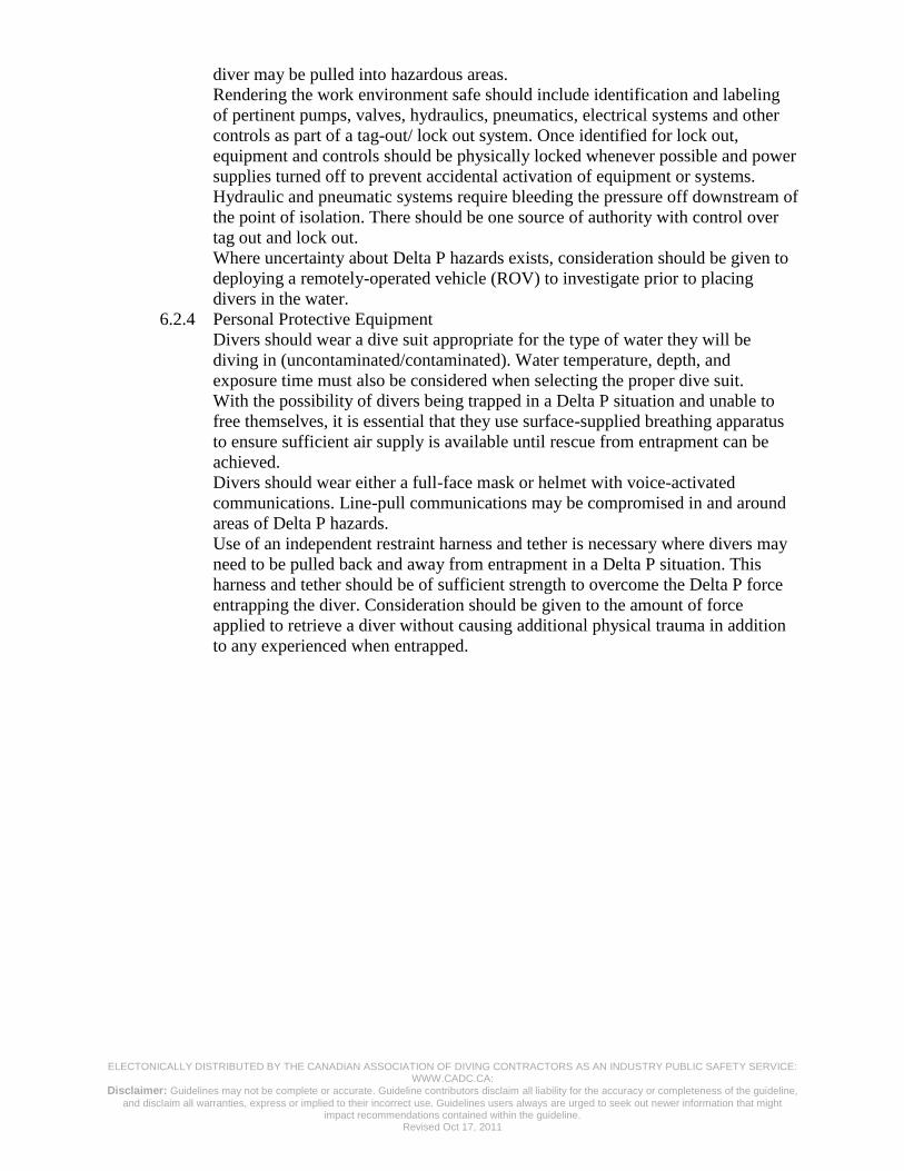
diver may be pulled into hazardous areas.
Rendering the work environment safe should include identification and labeling
of pertinent pumps, valves, hydraulics, pneumatics, electrical systems and other
controls as part of a tag-out/ lock out system. Once identified for lock out,
equipment and controls should be physically locked whenever possible and power
supplies turned off to prevent accidental activation of equipment or systems.
Hydraulic and pneumatic systems require bleeding the pressure off downstream of
the point of isolation. There should be one source of authority with control over
tag out and lock out.
Where uncertainty about Delta P hazards exists, consideration should be given to
deploying a remotely-operated vehicle (ROV) to investigate prior to placing
divers in the water.
6.2.4 Personal Protective Equipment
Divers should wear a dive suit appropriate for the type of water they will be
diving in (uncontaminated/contaminated). Water temperature, depth, and
exposure time must also be considered when selecting the proper dive suit.
With the possibility of divers being trapped in a Delta P situation and unable to
free themselves, it is essential that they use surface-supplied breathing apparatus
to ensure sufficient air supply is available until rescue from entrapment can be
achieved.
Divers should wear either a full-face mask or helmet with voice-activated
communications. Line-pull communications may be compromised in and around
areas of Delta P hazards.
Use of an independent restraint harness and tether is necessary where divers may
need to be pulled back and away from entrapment in a Delta P situation. This
harness and tether should be of sufficient strength to overcome the Delta P force
entrapping the diver. Consideration should be given to the amount of force
applied to retrieve a diver without causing additional physical trauma in addition
to any experienced when entrapped.

ELECTONICALLY DISTRIBUTED BY THE CANADIAN ASSOCIATION OF DIVING CONTRACTORS AS AN INDUSTRY PUBLIC SAFETY SERVICE: WWW.CADC.CA:
Disclaimer: Guidelines may not be complete or accurate. Guideline contributors disclaim all liability for the accuracy or completeness of the guideline,
and disclaim all warranties, express or implied to their incorrect use. Guidelines users always are urged to seek out newer information that might impact recommendations contained within the guideline.
Revised Oct 17, 2011
Rudders & Nozzles Thrusters Sea Chests
Props and Shafts Recessed SonarsIntakes and Outlets
Sonar Bulbs
Delta P and Other Diving Hazards
ELECTONICALLY DISTRIBUTED BY THE CANADIAN ASSOCIATION OF DIVING CONTRACTORS AS AN INDUSTRY PUBLIC SAFETY SERVICE: WWW.CADC.CA:
Disclaimer: Guidelines may not be complete or accurate. Guideline contributors disclaim all liability for the accuracy or completeness of the guideline,
and disclaim all warranties, express or implied to their incorrect use. Guidelines users always are urged to seek out newer information that might impact recommendations contained within the guideline.
Revised Oct 17, 2011
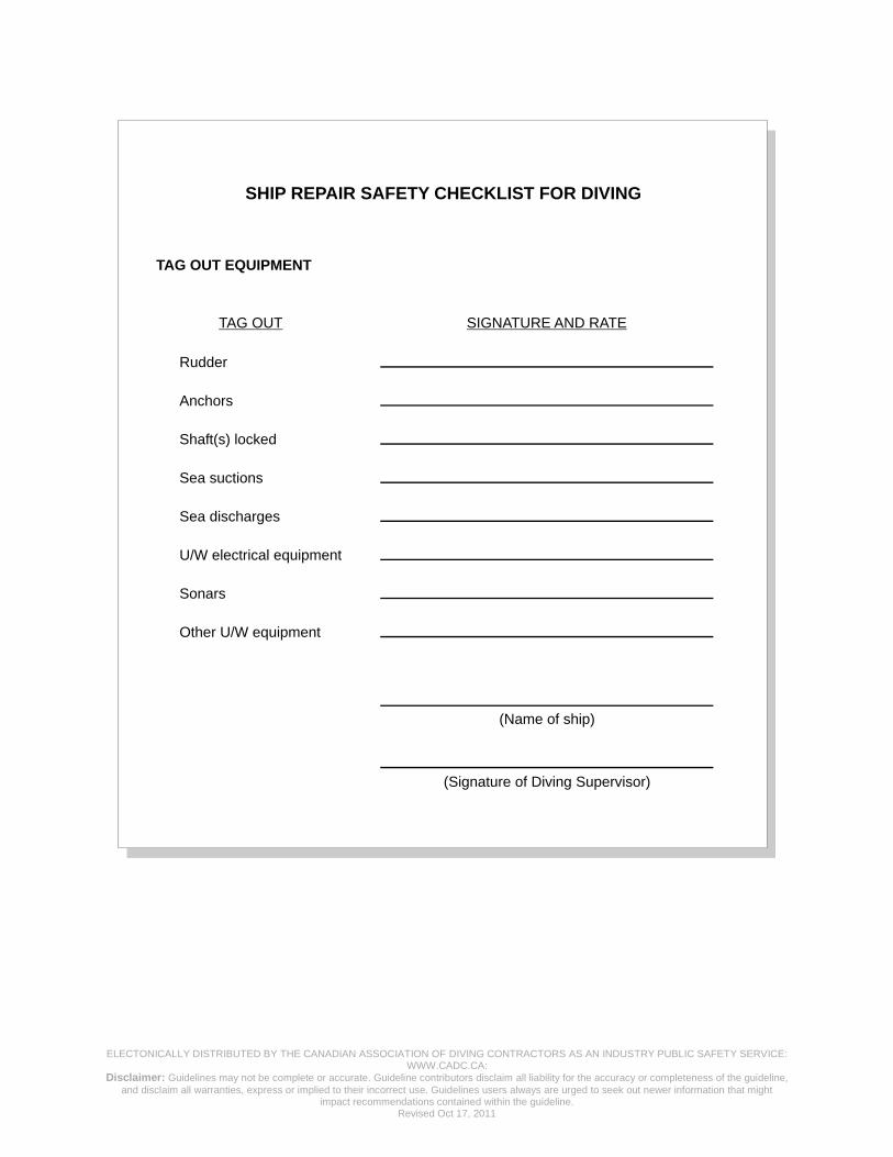
SHIP REPAIR SAFETY CHECKLIST FOR DIVING
TAG OUT EQUIPMENT
TAG OUT
Rudder
Anchors
Shaft(s) locked
Sea suctions
Sea discharges
U/W electrical equipment
Sonars
Other U/W equipment
SIGNATURE AND RATE
(Name of ship)
(Signature of Diving Supervisor)