dell emc mainframe technology overview...ibm’s more costly and complex gdps service offering...
TRANSCRIPT
WHITE PAPER
DELL EMC MAINFRAME TECHNOLOGY OVERVIEW
ABSTRACT This white paper provides an overview of Dell EMC’s product offerings for the IBM Z & IBM z/TPF environment. It is intended for customers or prospective customers interested in understanding both Dell EMC’s mainframe compatibility offerings as well as innovative and unique capabilities offered by Dell EMC for IBM users.
September 2019
2
Revisions Date Description
August 2019 Revision 0.9 which includes content related to OS 5978 SR (Q3 2019) as well as reformatting and attributions of the prior release 0.8
Acknowledgements This paper was produced by the following: Authors: Brett Quinn, Bruce Klenk, Paul Scheuer Support: Mainframe Corporate Systems Engineering
The information in this publication is provided as is. Dell Inc. makes no representations or warranties of any kind with respect to the information in this publication and specifically disclaims implied warranties of merchantability or fitness for a particular purpose. Use, copying, and distribution of any software described in this publication requires an applicable software license. Copyright © 2019 Dell Inc. or its subsidiaries. All Rights Reserved. Dell, EMC, and other trademarks are trademarks of Dell Inc. or its subsidiaries. Other trademarks may be the property of their respective owners. September 2019. White paper h6109.9
3
TABLE OF CONTENTS
EXECUTIVE SUMMARY ...........................................................................................................5
INTRODUCTION TO DELL EMC MAINFRAME PRODUCTS ..................................................5 Dell EMC storage arrays for Mainframe ............................................................................................ 5
Powermax 8000 storage array for Mainframe ................................................................................... 6
VMAX 950F storage array for Mainframe .......................................................................................... 6
NEW Mainframe Features in PowerMAXOs and HYPERMAX OS.................................................... 8
IBM Z Compatibility support .............................................................................................................. 8
DELL EMC OPTIMIZER FAMILY ..............................................................................................9 PAV Optimizer ................................................................................................................................... 9
Mirror Optimizer ............................................................................................................................... 11
FLASHBOOST ........................................................................................................................ 13
DATA PROTECTION .............................................................................................................. 13 SRDF Family of Products for Z/OS .................................................................................................. 13
Concurrent SRDF ........................................................................................................................................ 14
Cascaded SRDF ......................................................................................................................................... 15
SRDF/Star ................................................................................................................................................... 15
SRDF/SQAR ................................................................................................................................... 16
AutoSwap for Z/OS .......................................................................................................................... 17
Dell EMC TimeFinder SnapVX for Z/OS .......................................................................................... 18
ZDP™ –DATA PROTECTOR FOR Z SYSTEMS ................................................................... 19 ZDP enhancements as oF OS 5978 SR (Q3 2019) ......................................................................... 19
DISK LIBRARY FOR MAINFRAME (DLM) ............................................................................ 20
A.R.M. YOUR DATACENTER WITH GDDR .......................................................................... 23 Supported business continuity configurations .............................................................................................. 24
Universal Data Consistency: GDDR and Disk Library for Mainframe (DLm) ................................................ 24
GDDR Tape – DLm DR failover automation solution ...................................................................... 25
STORAGE MANAGEMENT SOFTWARE .............................................................................. 26 Mainframe Enablers ........................................................................................................................ 26
Unisphere ........................................................................................................................................ 27
Connectrix B-Series for Mainframe ................................................................................................. 28
Connectrix MDS Series for Mainframe ............................................................................................ 29
4
DATA MIGRATION WITH Z/OS MIGRATOR ........................................................................ 29
SUMMARY .............................................................................................................................. 30
5
EXECUTIVE SUMMARY The mainframe platform remains the focal point for transaction processing that securely holds the data for the ‘systems of record’ in most large financial, government, health care, insurance, and manufacturing enterprises around the globe. These organizations continue to invest in technology that manages and protects this critical data. They are constantly searching for innovative solutions that reduce the cost of operations, improve availability, and protect the integrity of data on this mission critical platform.
Dell EMC has a 25+ year history of innovation in mainframe storage solutions that offer users a choice in how they manage and protect the most critical component of their mainframe investment: their data. This paper provides an overview of Dell EMC’s hardware and software product offerings for mainframe data management and protection.
Dell EMC’s flagship Mainframe DASD offerings, the PowerMax 8000 and VMAX 950F All Flash array, offer customers full compatibility with key IBM Z technologies, such a High Performance FICON, while also providing innovative solutions for data protection and recovery such as z Systems Data Protector, or zDP. The Symmetrix Remote Data Facility (SRDF) product and its flexible three and four site configuration options, SRDF/Star and SRDF/SQAR, offer much faster deployment and simpler management with Dell EMC’s GDDR automation solution, the only competitive alternative to IBM’s more costly and complex GDPS service offering available in the market.
A decade ago, Dell EMC rocked the IBM tape marketplace with the introduction of the Disk Library for mainframe (DLm), a ‘tape on disk’ solution designed to eliminate physical tape forever from the modern mainframe datacenter. Since that time DLm has taken the leadership position for tape subsystems and many users have implemented DLm to completely remove physical tape from their operations. DLm provides dramatically improved run times for tape processing, dramatic reductions in tape footprint and resultant TCO, and a cloud option for storage of long term archived tape data.
Dell EMC mainframe engineering is committed to two principles when developing solutions for the mainframe marketplace: compatibility and innovation, which combined yield value and choice for the IBM Z user. Please read on, we believe you will be suitably impressed.
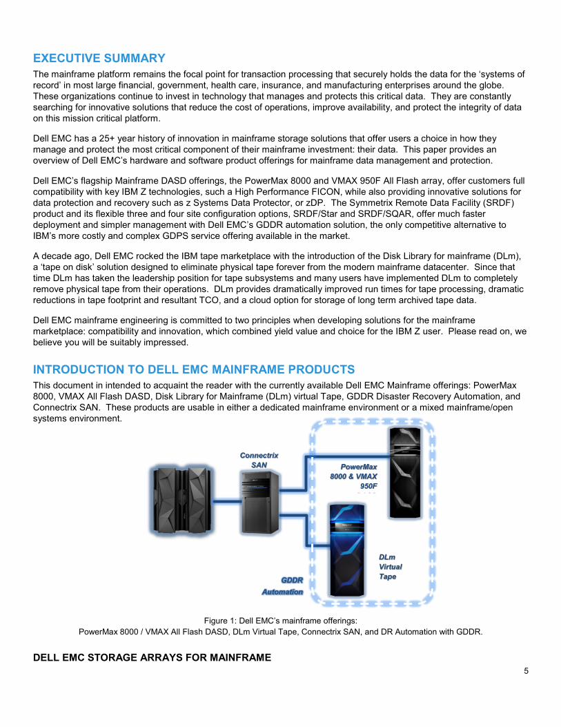
INTRODUCTION TO DELL EMC MAINFRAME PRODUCTS This document in intended to acquaint the reader with the currently available Dell EMC Mainframe offerings: PowerMax 8000, VMAX All Flash DASD, Disk Library for Mainframe (DLm) virtual Tape, GDDR Disaster Recovery Automation, and Connectrix SAN. These products are usable in either a dedicated mainframe environment or a mixed mainframe/open systems environment.
Figure 1: Dell EMC’s mainframe offerings: PowerMax 8000 / VMAX All Flash DASD, DLm Virtual Tape, Connectrix SAN, and DR Automation with GDDR.
DELL EMC STORAGE ARRAYS FOR MAINFRAME
Connectrix SAN
DLm Virtual Tape
PowerMax 8000 & VMAX
950F DASD
GDDR Automation

6
Dell EMC offers two arrays with FICON connectivity for mainframe environments, the PowerMax 8000 and the VMAX 950F All Flash Array. These arrays use the same engine technology, based on the Intel Broadwell processor and the Virtual Matrix interconnect, based on 56Gb/s Infiniband. They differ in the backend flash drive technology and protocols used, as well as the packaging for the Drive Array Enclosures. Both offerings are described below.
POWERMAX 8000 STORAGE ARRAY FOR MAINFRAME The PowerMax 8000 is the first Dell EMC hardware platform with a storage back-end that uses Intel® Optane™ Storage Class memory (SCM) and Non-Volatile Memory Express (NVMe) for customer data. NVMe is a set of standards which define a PCI Express (PCIe) interface used to efficiently access storage devices based on Non-Volatile Memory (NVM) media, which includes today’s NAND-based flash along with Storage Class Memory (SCM) The NVMe-based PowerMax was specifically created to fully unlock the bandwidth, IOPS, and latency performance benefits that NVM media offers which are unattainable using the current generation all flash storage arrays, and intended for use with host workloads that utilize the backend of the array more extensively during normal I/O processing.
The PowerMax 8000 platform includes: • 1 – 8 zPowerBricks per system • 2 x 18 core, 2.8 GHz, Intel Broadwell CPUs yielding 72 cores per zPowerBrick • 1 TB, 2 TB DDR4 cache per zPowerBrick (up to 16 TB total) • Up to 256 FICON ports per system • Up to 288 NVM drives supporting up to 1.7 PBu CKD capacity per system of PCIe Gen3 NVMe storage in two
racks • Open systems and/or mainframe support while offering data reduction for non-mainframe data. • 24 slot NVMe DAE using 2.5” form factor 1.92 TB, 3.84 TB, or 7.68 TB NVMe Drives • Dual ported NVMe PCIe Gen3 (8 lane) backend I/O interface modules (4 per engine) delivering 8 GB/sec of
bandwidth per module (32 GB/sec per engine) to NVMe or SCM storage
The core of the zPowerBrick is an engine. The engine is the central I/O processing unit, redundantly built for high availability. It consists of:
• Redundant directors each containing two Intel Broadwell processors of 18 physical cores each, and interfaces to universal I/O modules, such as front-end, back-end, InfiniBand, and flash I/O modules
• Two 2U 24-slot, dual-ported, 2.5” PCIe Optane DAEs (DAE24), either 750GB or 1.5TB each, with a base storage capacity of 13TBu.
• Two 2U 24-slot, dual-ported, 2.5” PCIe NVMe DAEs (DAE24) supporting 1.92TB, 3.84TB, and 7.68TB NVMe drives as well as 750GB or 1.5TB SCM drives with a base storage capacity for the DAE of 13TBu.
Customers can scale up the initial configuration by adding 13 TBu zFlash capacity packs that bundle all required flash capacity and software. In addition, customers can also scale out the initial configuration by adding additional zPowerBricks to increase performance, connectivity, and throughput. Independent and linear scaling of both capacity and performance enables PowerMax to be extremely flexible at addressing varying workloads. Many mainframe systems can fit all the processing and storage they need into two zPowerBricks, which typically fits within a single data center floor tile.
VMAX 950F STORAGE ARRAY FOR MAINFRAME VMAX 950F All Flash storage arrays are engineered to deliver the highest possible performance and density while offering the lowest TCO available. The power of VMAX arrays is their flexibility to grow performance and capacity independently to address a massive variety of real world workloads. All Flash arrays offer the simplest packaging ever delivered for a VMAX platform. The basic building block for a mainframe VMAX 950F is the zBrick that consists of:
• An engine (the high-availability data storage processing unit) consisting of two directors each containing two Intel Broadwell processors of 18 physical cores each, and interfaces to universal I/O modules, such as front-end, back-end, InfiniBand, and flash I/O modules.
Two 4U Drive Array Enclosures (DAEs) that house up to 120 6 Gb/s SAS attached 2.5” TLC flash drives of 960GB, 1.92TB, 3.84TB, 7.68TB, or 15.36TB with a base storage capacity, of 13 TBu. Customers can scale up the initial
7
configuration by adding 13 TBu zCapacity packs that bundle all required flash capacity and software. In addition, customers can also scale out the initial configuration by adding additional zBricks to increase performance, connectivity, and throughput. Independent and linear scaling of both capacity and performance enables VMAX to be extremely flexible at addressing varying workloads. Many mainframe systems can fit all the processing and storage they need into two zBricks, which typically fits within a single data center floor tile.
The VMAX 950F array addresses mainframe or mixed storage needs and consists of:
• 1-8 zBricks per system • Up to 16 TB Cache • Up to 1,920 2.5” Flash Drives • Up to 256 FICON ports. • Support for mixed configurations (Open Systems, IBM i, and/or File along with CKD), while offering compression for
non-mainframe data.
Both the PowerMax 8000 and the VMAX 950F All Flash Array deliver high scale, low latency, and rich data services for mainframe environments by leveraging the following capabilities of the PowerMaxOS and HYPERMAX OS 5978 code family:
• Dynamic Virtual Matrix Architecture that enables inter-director communications over redundant internal InfiniBand fabrics
• Embedded hypervisor to provide management services which previously executed on an external LUW server • Unprecedented levels of performance and scale driven by massively parallel processing due to exploitation of Intel’s
SMT2 support. • An eight zBrick VMAX 950F or an eight zPowerBrick PowerMax 8000 can employ 576 Intel processor cores to
process I/O requests. PowerMaxOS and HYPERMAX OS exploits the SMT2 feature of the Intel processors, yielding an effective 1152 logical processor cores, which results in significant IOPS per engine and response time improvement.
• Mainframe host connectivity (including full zHPF support at 16 Gb/s) for mission critical storage needs • Industry-leading data services such as SRDF remote replication technology and TimeFinder local replication services,
based on the space efficient SnapVX infrastructure. • Leverages the latest Flash drive technology in zBricks, zPowerBricks, zCapacity and zFlash capacity packs of 13 TBu
increments to deliver a top-tier service level. • Data at Rest Encryption (D@RE) providing hardware-based, on-array, back-end encryption using hardware assists on
the disk adapter for encryption with no performance impact. • Support for thin CKD devices (TDEVs) with an allocation granularity of a single CKD track (56KB). CONSOLIDATION
The PowerMax 8000 and the VMAX 950F offer substantial opportunities for consolidation in the form of:
• Substantial footprint reductions due to increased IOPS per engine. For example, a 6-bay 4 engine VMAX 20K can be refreshed with a single bay two-engine 950F.
• Support for mixed configurations (Open Systems, IBM i, and/or File along with CKD), while offering compression for non-mainframe data. This enables small amounts of mainframe to be included with open systems configurations while maintaining minimum footprint, consolidated management, and overall reduced TCO.
VIRTUAL PROVISIONING (VP) AND FACTORY PRE-CONFIGURATION
8
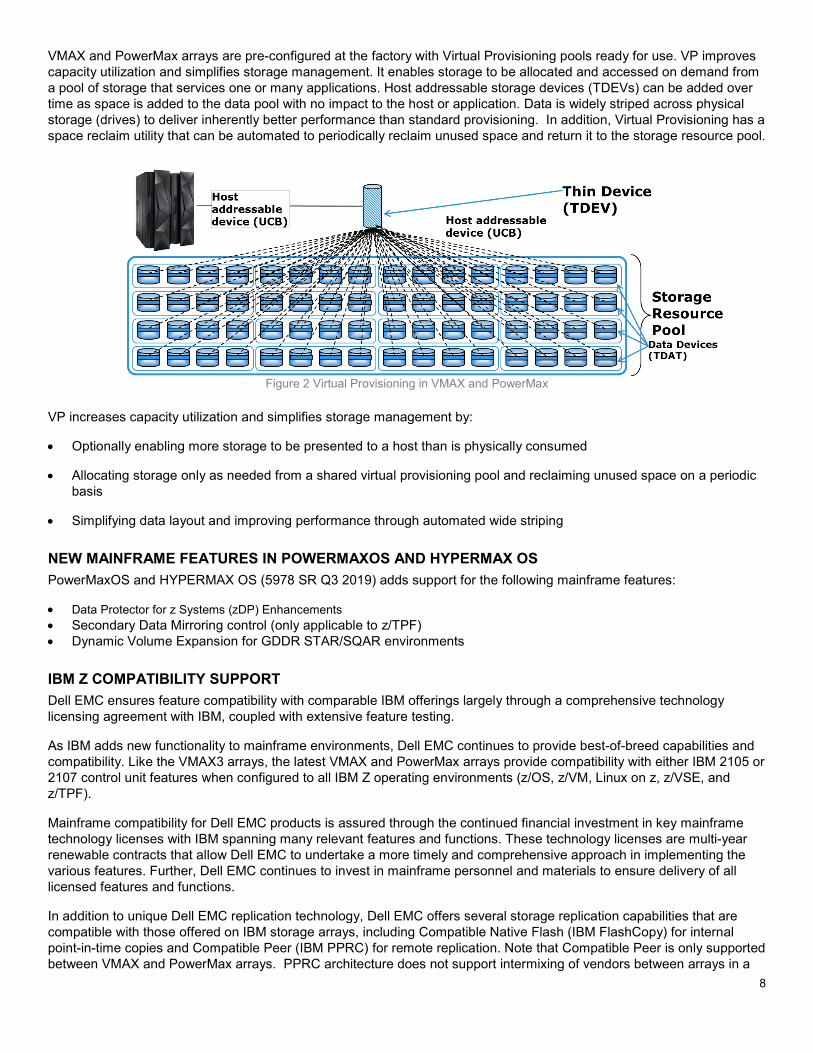
VMAX and PowerMax arrays are pre-configured at the factory with Virtual Provisioning pools ready for use. VP improves capacity utilization and simplifies storage management. It enables storage to be allocated and accessed on demand from a pool of storage that services one or many applications. Host addressable storage devices (TDEVs) can be added over time as space is added to the data pool with no impact to the host or application. Data is widely striped across physical storage (drives) to deliver inherently better performance than standard provisioning. In addition, Virtual Provisioning has a space reclaim utility that can be automated to periodically reclaim unused space and return it to the storage resource pool.
Figure 2 Virtual Provisioning in VMAX and PowerMax VP increases capacity utilization and simplifies storage management by:
• Optionally enabling more storage to be presented to a host than is physically consumed
• Allocating storage only as needed from a shared virtual provisioning pool and reclaiming unused space on a periodic basis
• Simplifying data layout and improving performance through automated wide striping
NEW MAINFRAME FEATURES IN POWERMAXOS AND HYPERMAX OS PowerMaxOS and HYPERMAX OS (5978 SR Q3 2019) adds support for the following mainframe features:
• Data Protector for z Systems (zDP) Enhancements • Secondary Data Mirroring control (only applicable to z/TPF) • Dynamic Volume Expansion for GDDR STAR/SQAR environments
IBM Z COMPATIBILITY SUPPORT Dell EMC ensures feature compatibility with comparable IBM offerings largely through a comprehensive technology licensing agreement with IBM, coupled with extensive feature testing.
As IBM adds new functionality to mainframe environments, Dell EMC continues to provide best-of-breed capabilities and compatibility. Like the VMAX3 arrays, the latest VMAX and PowerMax arrays provide compatibility with either IBM 2105 or 2107 control unit features when configured to all IBM Z operating environments (z/OS, z/VM, Linux on z, z/VSE, and z/TPF).
Mainframe compatibility for Dell EMC products is assured through the continued financial investment in key mainframe technology licenses with IBM spanning many relevant features and functions. These technology licenses are multi-year renewable contracts that allow Dell EMC to undertake a more timely and comprehensive approach in implementing the various features. Further, Dell EMC continues to invest in mainframe personnel and materials to ensure delivery of all licensed features and functions.
In addition to unique Dell EMC replication technology, Dell EMC offers several storage replication capabilities that are compatible with those offered on IBM storage arrays, including Compatible Native Flash (IBM FlashCopy) for internal point-in-time copies and Compatible Peer (IBM PPRC) for remote replication. Note that Compatible Peer is only supported between VMAX and PowerMax arrays. PPRC architecture does not support intermixing of vendors between arrays in a
9
PPRC relationship, although multiple vendors’ PPRC pairs can coexist in a single environment. The table below lists the IBM features for which VMAX and PowerMax arrays provide compatibility:
Technology Features Supported
IBM Replication • Metro Mirror (formerly PPRC) • Global Copy (formerly PPRC-XD) • GDPS/PPRC, GPDS/HM
(including Enhanced Conditional FREEZE and Non-Disruptive State Save)
• FlashCopy V1 and V2 (including Remote Pair Flashcopy and Multi-Incremental Flashcopy)
• HyperSwap (Including Soft Fence) IBM Channel Compatibility • Parallel Access Volume (PAV)
• Dynamic Parallel Access Volume (DPAV) • HyperPAV, SuperPAV • Multiple Allegiance (MA) • Modified Indirect Data Address Word (MIDAW) • SPID Fence • Extended Address Volume (EAV) – 1 TB • Priority I/O Queuing • Concurrent Copy • Sequential Data Striping • Partitioned Dataset Search Assist • Query Host Access • zHyperWrite • zEDC • zDAC • zHPF- single and Multi-track
(including List Prefetch, BSAM/QSAM, Format writes, Bi-Di transfers)
• Forward Error Correction • zHPF Extended Distance II FICON • zDDB • zFBA • IMS WADS performance enhancements • Dynamic Volume Expansion (DVE)
DELL EMC OPTIMIZER FAMILY
Users of the IBM Z mainframe demand high I/O throughput rates and low response times for the mission critical applications that run their businesses. Dell EMC has a long history of delivering the best product for these environments in terms of reliability, availability, and performance. One of the hallmarks of this commitment is the development of innovative solutions to customer problems. Mirror Optimizer and PAV Optimizer are one such example of unique Dell EMC innovation that provides performance enhancements for VMAX and PowerMax Mainframe users
PAV OPTIMIZER PAV Optimizer leverages two technology advances in recent years that have impacted the mainframe marketplace: 1) the release of High Performance FICON (zHPF) and 2) increasing usage of parallel processing in software and hardware design to address the plateauing of single thread performance within computing platforms.
IBM developed High Performance FICON to improve the throughput of the FICON I/O subsystem on the z System server and achieved very high data transfer rates as a result. These capabilities have been implemented by the media manager component of z/OS, with most access methods now exploiting zHPF. The result of this exploitation has created a fundamental shift over time in the composition of z/OS I/O with the trend today being much larger I/O data transfer sizes due to multiple DASD tracks being transferred in a single I/O operation. This is the major reason why zHPF is able to achieve such high throughput rates.
10
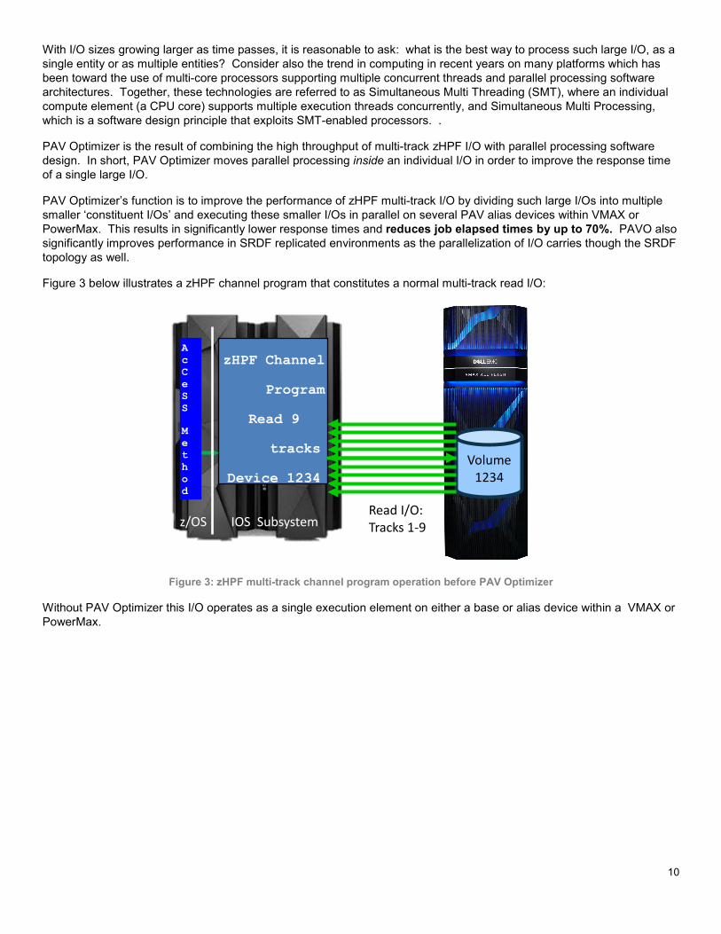
With I/O sizes growing larger as time passes, it is reasonable to ask: what is the best way to process such large I/O, as a single entity or as multiple entities? Consider also the trend in computing in recent years on many platforms which has been toward the use of multi-core processors supporting multiple concurrent threads and parallel processing software architectures. Together, these technologies are referred to as Simultaneous Multi Threading (SMT), where an individual compute element (a CPU core) supports multiple execution threads concurrently, and Simultaneous Multi Processing, which is a software design principle that exploits SMT-enabled processors. .
PAV Optimizer is the result of combining the high throughput of multi-track zHPF I/O with parallel processing software design. In short, PAV Optimizer moves parallel processing inside an individual I/O in order to improve the response time of a single large I/O.
PAV Optimizer’s function is to improve the performance of zHPF multi-track I/O by dividing such large I/Os into multiple smaller ‘constituent I/Os’ and executing these smaller I/Os in parallel on several PAV alias devices within VMAX or PowerMax. This results in significantly lower response times and reduces job elapsed times by up to 70%. PAVO also significantly improves performance in SRDF replicated environments as the parallelization of I/O carries though the SRDF topology as well.
Figure 3 below illustrates a zHPF channel program that constitutes a normal multi-track read I/O:
Figure 3: zHPF multi-track channel program operation before PAV Optimizer
Without PAV Optimizer this I/O operates as a single execution element on either a base or alias device within a VMAX or PowerMax.
z/OS IOS Subsystem
zHPF Channel
Program
Read 9
tracks
Device 1234 Volume
1234
Read I/O: Tracks 1-9
A c C e S S M e t h o d
11
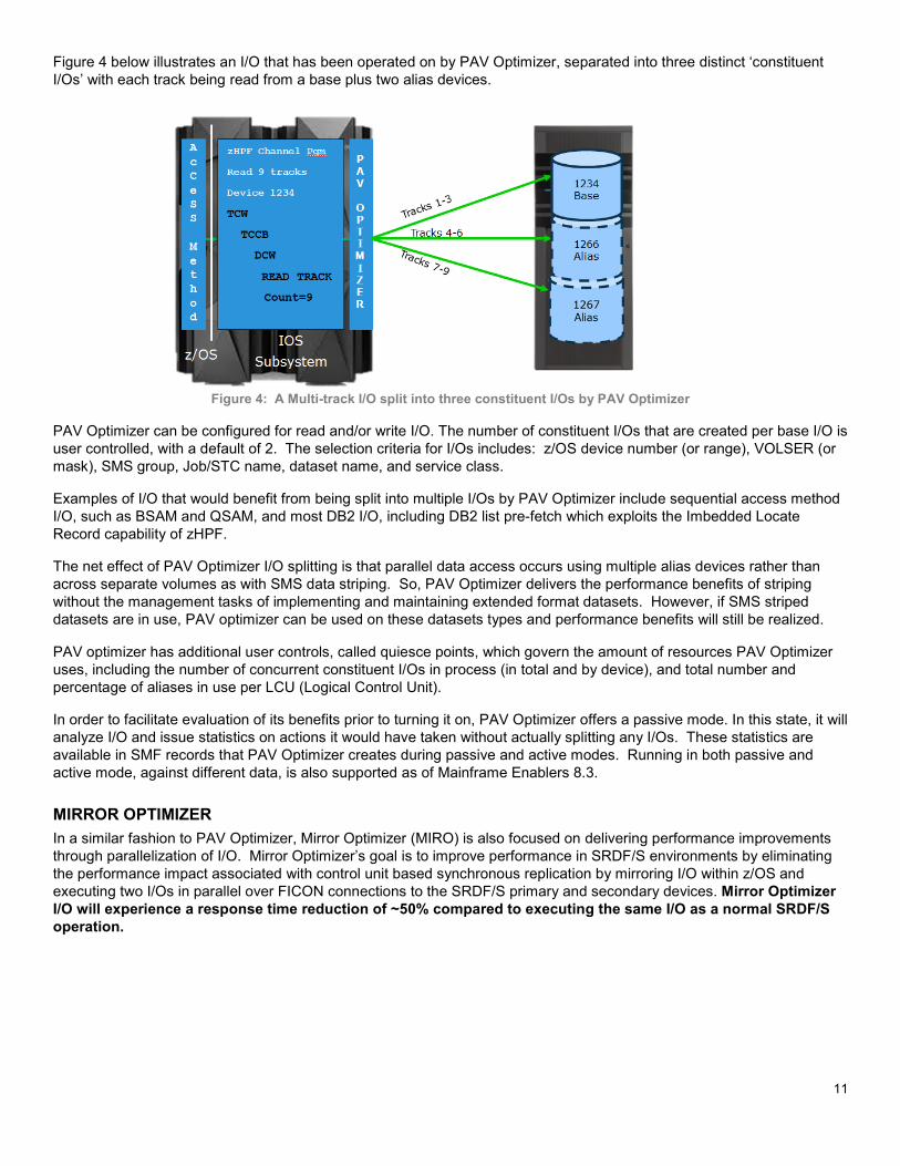
Figure 4 below illustrates an I/O that has been operated on by PAV Optimizer, separated into three distinct ‘constituent I/Os’ with each track being read from a base plus two alias devices.
Figure 4: A Multi-track I/O split into three constituent I/Os by PAV Optimizer
PAV Optimizer can be configured for read and/or write I/O. The number of constituent I/Os that are created per base I/O is user controlled, with a default of 2. The selection criteria for I/Os includes: z/OS device number (or range), VOLSER (or mask), SMS group, Job/STC name, dataset name, and service class.
Examples of I/O that would benefit from being split into multiple I/Os by PAV Optimizer include sequential access method I/O, such as BSAM and QSAM, and most DB2 I/O, including DB2 list pre-fetch which exploits the Imbedded Locate Record capability of zHPF.
The net effect of PAV Optimizer I/O splitting is that parallel data access occurs using multiple alias devices rather than across separate volumes as with SMS data striping. So, PAV Optimizer delivers the performance benefits of striping without the management tasks of implementing and maintaining extended format datasets. However, if SMS striped datasets are in use, PAV optimizer can be used on these datasets types and performance benefits will still be realized.
PAV optimizer has additional user controls, called quiesce points, which govern the amount of resources PAV Optimizer uses, including the number of concurrent constituent I/Os in process (in total and by device), and total number and percentage of aliases in use per LCU (Logical Control Unit).
In order to facilitate evaluation of its benefits prior to turning it on, PAV Optimizer offers a passive mode. In this state, it will analyze I/O and issue statistics on actions it would have taken without actually splitting any I/Os. These statistics are available in SMF records that PAV Optimizer creates during passive and active modes. Running in both passive and active mode, against different data, is also supported as of Mainframe Enablers 8.3.
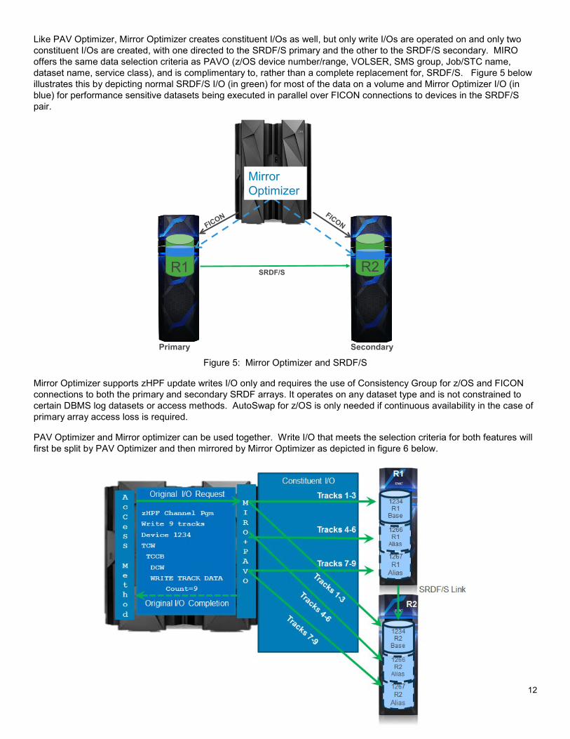
MIRROR OPTIMIZER In a similar fashion to PAV Optimizer, Mirror Optimizer (MIRO) is also focused on delivering performance improvements through parallelization of I/O. Mirror Optimizer’s goal is to improve performance in SRDF/S environments by eliminating the performance impact associated with control unit based synchronous replication by mirroring I/O within z/OS and executing two I/Os in parallel over FICON connections to the SRDF/S primary and secondary devices. Mirror Optimizer I/O will experience a response time reduction of ~50% compared to executing the same I/O as a normal SRDF/S operation.
12
Like PAV Optimizer, Mirror Optimizer creates constituent I/Os as well, but only write I/Os are operated on and only two constituent I/Os are created, with one directed to the SRDF/S primary and the other to the SRDF/S secondary. MIRO offers the same data selection criteria as PAVO (z/OS device number/range, VOLSER, SMS group, Job/STC name, dataset name, service class), and is complimentary to, rather than a complete replacement for, SRDF/S. Figure 5 below illustrates this by depicting normal SRDF/S I/O (in green) for most of the data on a volume and Mirror Optimizer I/O (in blue) for performance sensitive datasets being executed in parallel over FICON connections to devices in the SRDF/S pair.
Figure 5: Mirror Optimizer and SRDF/S
Mirror Optimizer supports zHPF update writes I/O only and requires the use of Consistency Group for z/OS and FICON connections to both the primary and secondary SRDF arrays. It operates on any dataset type and is not constrained to certain DBMS log datasets or access methods. AutoSwap for z/OS is only needed if continuous availability in the case of primary array access loss is required.
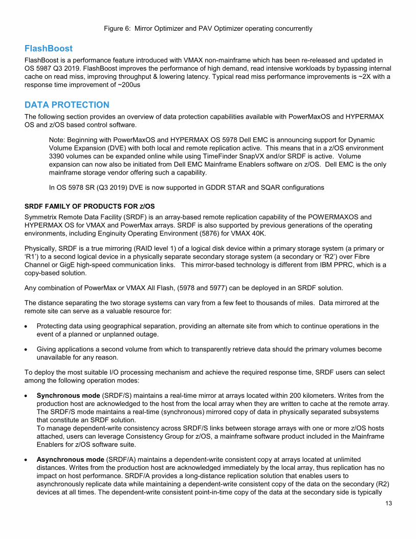
PAV Optimizer and Mirror optimizer can be used together. Write I/O that meets the selection criteria for both features will first be split by PAV Optimizer and then mirrored by Mirror Optimizer as depicted in figure 6 below.
SRDF/S
Primary Secondary
R2R1
Mirror Optimizer
13
Figure 6: Mirror Optimizer and PAV Optimizer operating concurrently
FlashBoost FlashBoost is a performance feature introduced with VMAX non-mainframe which has been re-released and updated in OS 5987 Q3 2019. FlashBoost improves the performance of high demand, read intensive workloads by bypassing internal cache on read miss, improving throughput & lowering latency. Typical read miss performance improvements is ~2X with a response time improvement of ~200us
DATA PROTECTION The following section provides an overview of data protection capabilities available with PowerMaxOS and HYPERMAX OS and z/OS based control software.
Note: Beginning with PowerMaxOS and HYPERMAX OS 5978 Dell EMC is announcing support for Dynamic Volume Expansion (DVE) with both local and remote replication active. This means that in a z/OS environment 3390 volumes can be expanded online while using TimeFinder SnapVX and/or SRDF is active. Volume expansion can now also be initiated from Dell EMC Mainframe Enablers software on z/OS. Dell EMC is the only mainframe storage vendor offering such a capability.
In OS 5978 SR (Q3 2019) DVE is now supported in GDDR STAR and SQAR configurations
SRDF FAMILY OF PRODUCTS FOR Z/OS Symmetrix Remote Data Facility (SRDF) is an array-based remote replication capability of the POWERMAXOS and HYPERMAX OS for VMAX and PowerMax arrays. SRDF is also supported by previous generations of the operating environments, including Enginuity Operating Environment (5876) for VMAX 40K.
Physically, SRDF is a true mirroring (RAID level 1) of a logical disk device within a primary storage system (a primary or ‘R1’) to a second logical device in a physically separate secondary storage system (a secondary or ‘R2’) over Fibre Channel or GigE high-speed communication links. This mirror-based technology is different from IBM PPRC, which is a copy-based solution.
Any combination of PowerMax or VMAX All Flash, (5978 and 5977) can be deployed in an SRDF solution.
The distance separating the two storage systems can vary from a few feet to thousands of miles. Data mirrored at the remote site can serve as a valuable resource for:
• Protecting data using geographical separation, providing an alternate site from which to continue operations in the event of a planned or unplanned outage.
• Giving applications a second volume from which to transparently retrieve data should the primary volumes become unavailable for any reason.
To deploy the most suitable I/O processing mechanism and achieve the required response time, SRDF users can select among the following operation modes:
• Synchronous mode (SRDF/S) maintains a real-time mirror at arrays located within 200 kilometers. Writes from the production host are acknowledged to the host from the local array when they are written to cache at the remote array. The SRDF/S mode maintains a real-time (synchronous) mirrored copy of data in physically separated subsystems that constitute an SRDF solution. To manage dependent-write consistency across SRDF/S links between storage arrays with one or more z/OS hosts attached, users can leverage Consistency Group for z/OS, a mainframe software product included in the Mainframe Enablers for z/OS software suite.
• Asynchronous mode (SRDF/A) maintains a dependent-write consistent copy at arrays located at unlimited distances. Writes from the production host are acknowledged immediately by the local array, thus replication has no impact on host performance. SRDF/A provides a long-distance replication solution that enables users to asynchronously replicate data while maintaining a dependent-write consistent copy of the data on the secondary (R2) devices at all times. The dependent-write consistent point-in-time copy of the data at the secondary side is typically
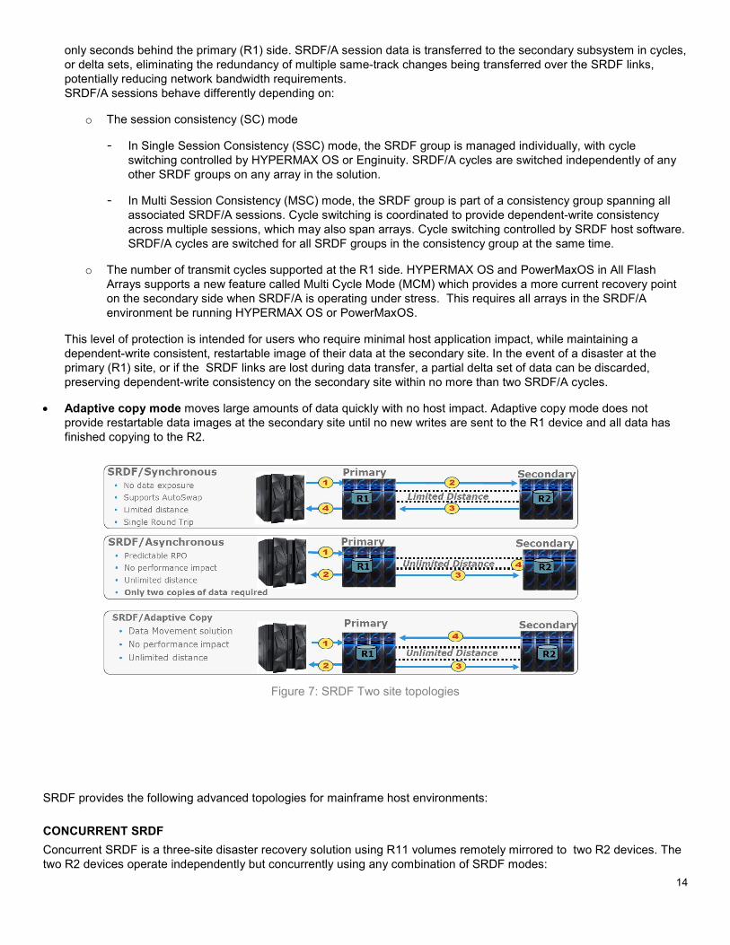
14
only seconds behind the primary (R1) side. SRDF/A session data is transferred to the secondary subsystem in cycles, or delta sets, eliminating the redundancy of multiple same-track changes being transferred over the SRDF links, potentially reducing network bandwidth requirements. SRDF/A sessions behave differently depending on:
o The session consistency (SC) mode
- In Single Session Consistency (SSC) mode, the SRDF group is managed individually, with cycle switching controlled by HYPERMAX OS or Enginuity. SRDF/A cycles are switched independently of any other SRDF groups on any array in the solution.
- In Multi Session Consistency (MSC) mode, the SRDF group is part of a consistency group spanning all associated SRDF/A sessions. Cycle switching is coordinated to provide dependent-write consistency across multiple sessions, which may also span arrays. Cycle switching controlled by SRDF host software. SRDF/A cycles are switched for all SRDF groups in the consistency group at the same time.
o The number of transmit cycles supported at the R1 side. HYPERMAX OS and PowerMaxOS in All Flash Arrays supports a new feature called Multi Cycle Mode (MCM) which provides a more current recovery point on the secondary side when SRDF/A is operating under stress. This requires all arrays in the SRDF/A environment be running HYPERMAX OS or PowerMaxOS.
This level of protection is intended for users who require minimal host application impact, while maintaining a dependent-write consistent, restartable image of their data at the secondary site. In the event of a disaster at the primary (R1) site, or if the SRDF links are lost during data transfer, a partial delta set of data can be discarded, preserving dependent-write consistency on the secondary site within no more than two SRDF/A cycles.
• Adaptive copy mode moves large amounts of data quickly with no host impact. Adaptive copy mode does not provide restartable data images at the secondary site until no new writes are sent to the R1 device and all data has finished copying to the R2.
Figure 7: SRDF Two site topologies
SRDF provides the following advanced topologies for mainframe host environments:
CONCURRENT SRDF Concurrent SRDF is a three-site disaster recovery solution using R11 volumes remotely mirrored to two R2 devices. The two R2 devices operate independently but concurrently using any combination of SRDF modes:
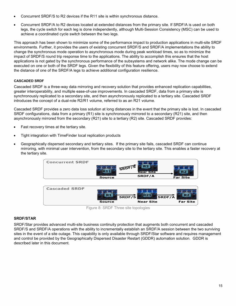
15
• Concurrent SRDF/S to R2 devices if the R11 site is within synchronous distance.
• Concurrent SRDF/A to R2 devices located at extended distances from the primary site. If SRDF/A is used on both legs, the cycle switch for each leg is done independently, although Multi-Session Consistency (MSC) can be used to achieve a coordinated cycle switch between the two legs.
This approach has been shown to minimize some of the performance impact to production applications in multi-site SRDF environments. Further, it provides the users of existing concurrent SRDF/S and SRDF/A implementations the ability to change the synchronous mode operation to asynchronous mode during peak workload times, so as to minimize the impact of SRDF/S round trip response time to the applications. The ability to accomplish this ensures that the host applications is not gated by the synchronous performance of the subsystems and network alike. The mode change can be executed on one or both of the SRDF legs. Given the flexibility of this feature offering, users may now choose to extend the distance of one of the SRDF/A legs to achieve additional configuration resilience.
CASCADED SRDF Cascaded SRDF is a three-way data mirroring and recovery solution that provides enhanced replication capabilities, greater interoperability, and multiple ease-of-use improvements. In cascaded SRDF, data from a primary site is synchronously replicated to a secondary site, and then asynchronously replicated to a tertiary site. Cascaded SRDF introduces the concept of a dual-role R2/R1 volume, referred to as an R21 volume.
Cascaded SRDF provides a zero data loss solution at long distances in the event that the primary site is lost. In cascaded SRDF configurations, data from a primary (R1) site is synchronously mirrored to a secondary (R21) site, and then asynchronously mirrored from the secondary (R21) site to a tertiary (R2) site. Cascaded SRDF provides:
• Fast recovery times at the tertiary site.
• Tight integration with TimeFinder local replication products
• Geographically dispersed secondary and tertiary sites. If the primary site fails, cascaded SRDF can continue mirroring, with minimal user intervention, from the secondary site to the tertiary site. This enables a faster recovery at the tertiary site.
Figure 8: SRDF Three site topologies
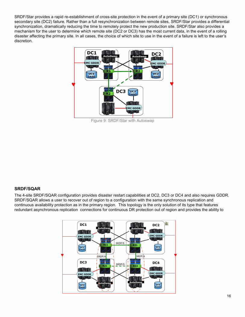
SRDF/STAR SRDF/Star provides advanced multi-site business continuity protection that augments both concurrent and cascaded SRDF/S and SRDF/A operations with the ability to incrementally establish an SRDF/A session between the two surviving sites in the event of a site outage. This capability is only available through SRDF/Star software and requires management and control be provided by the Geographically Dispersed Disaster Restart (GDDR) automation solution. GDDR is described later in this document.
16
SRDF/Star provides a rapid re-establishment of cross-site protection in the event of a primary site (DC1) or synchronous secondary site (DC2) failure. Rather than a full resynchronization between remote sites, SRDF/Star provides a differential synchronization, dramatically reducing the time to remotely protect the new production site. SRDF/Star also provides a mechanism for the user to determine which remote site (DC2 or DC3) has the most current data, in the event of a rolling disaster affecting the primary site. In all cases, the choice of which site to use in the event of a failure is left to the user’s discretion.
Figure 9: SRDF/Star with Autoswap
SRDF/SQAR The 4-site SRDF/SQAR configuration provides disaster restart capabilities at DC2, DC3 or DC4 and also requires GDDR. SRDF/SQAR allows a user to recover out of region to a configuration with the same synchronous replication and continuous availability protection as in the primary region. This topology is the only solution of its type that features redundant asynchronous replication connections for continuous DR protection out of region and provides the ability to
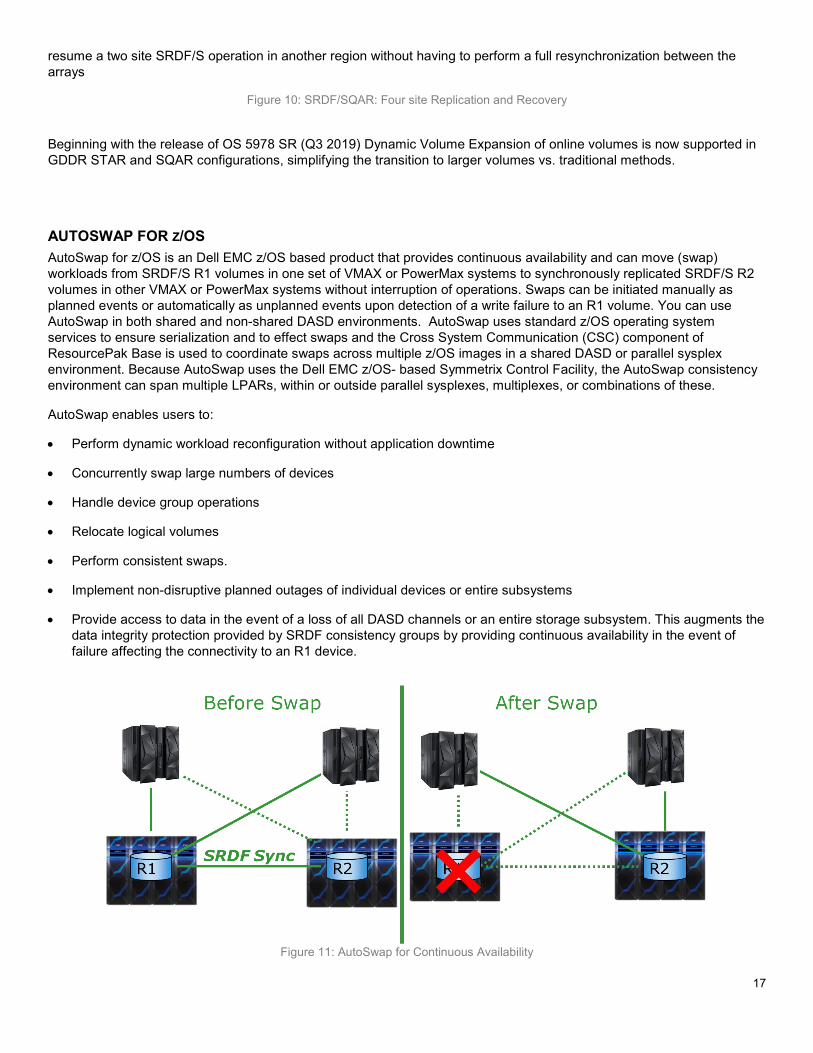
17
resume a two site SRDF/S operation in another region without having to perform a full resynchronization between the arrays
Figure 10: SRDF/SQAR: Four site Replication and Recovery
Beginning with the release of OS 5978 SR (Q3 2019) Dynamic Volume Expansion of online volumes is now supported in GDDR STAR and SQAR configurations, simplifying the transition to larger volumes vs. traditional methods.
AUTOSWAP FOR Z/OS AutoSwap for z/OS is an Dell EMC z/OS based product that provides continuous availability and can move (swap) workloads from SRDF/S R1 volumes in one set of VMAX or PowerMax systems to synchronously replicated SRDF/S R2 volumes in other VMAX or PowerMax systems without interruption of operations. Swaps can be initiated manually as planned events or automatically as unplanned events upon detection of a write failure to an R1 volume. You can use AutoSwap in both shared and non-shared DASD environments. AutoSwap uses standard z/OS operating system services to ensure serialization and to effect swaps and the Cross System Communication (CSC) component of ResourcePak Base is used to coordinate swaps across multiple z/OS images in a shared DASD or parallel sysplex environment. Because AutoSwap uses the Dell EMC z/OS- based Symmetrix Control Facility, the AutoSwap consistency environment can span multiple LPARs, within or outside parallel sysplexes, multiplexes, or combinations of these.
AutoSwap enables users to:
• Perform dynamic workload reconfiguration without application downtime
• Concurrently swap large numbers of devices
• Handle device group operations
• Relocate logical volumes
• Perform consistent swaps.
• Implement non-disruptive planned outages of individual devices or entire subsystems
• Provide access to data in the event of a loss of all DASD channels or an entire storage subsystem. This augments the data integrity protection provided by SRDF consistency groups by providing continuous availability in the event of failure affecting the connectivity to an R1 device.
Figure 11: AutoSwap for Continuous Availability
18
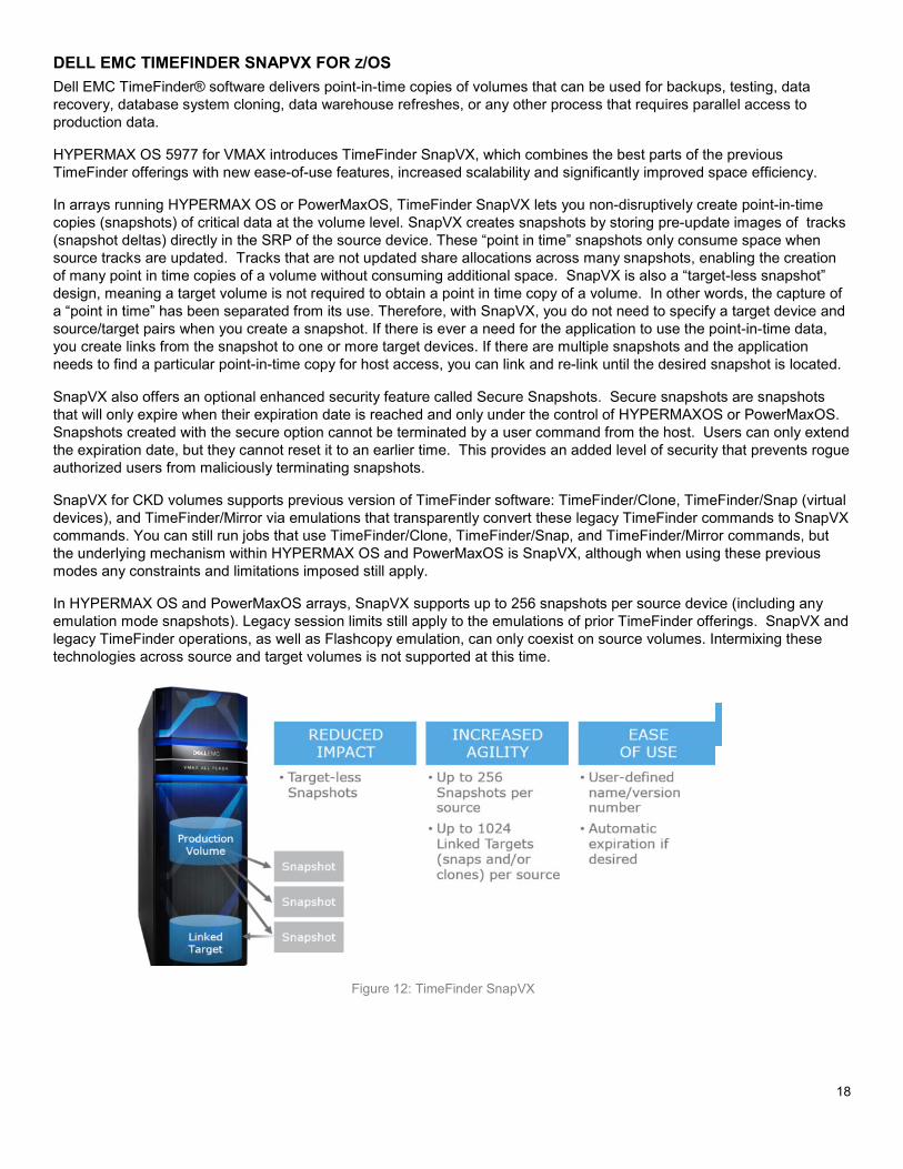
DELL EMC TIMEFINDER SNAPVX FOR Z/OS Dell EMC TimeFinder® software delivers point-in-time copies of volumes that can be used for backups, testing, data recovery, database system cloning, data warehouse refreshes, or any other process that requires parallel access to production data.
HYPERMAX OS 5977 for VMAX introduces TimeFinder SnapVX, which combines the best parts of the previous TimeFinder offerings with new ease-of-use features, increased scalability and significantly improved space efficiency.
In arrays running HYPERMAX OS or PowerMaxOS, TimeFinder SnapVX lets you non-disruptively create point-in-time copies (snapshots) of critical data at the volume level. SnapVX creates snapshots by storing pre-update images of tracks (snapshot deltas) directly in the SRP of the source device. These “point in time” snapshots only consume space when source tracks are updated. Tracks that are not updated share allocations across many snapshots, enabling the creation of many point in time copies of a volume without consuming additional space. SnapVX is also a “target-less snapshot” design, meaning a target volume is not required to obtain a point in time copy of a volume. In other words, the capture of a “point in time” has been separated from its use. Therefore, with SnapVX, you do not need to specify a target device and source/target pairs when you create a snapshot. If there is ever a need for the application to use the point-in-time data, you create links from the snapshot to one or more target devices. If there are multiple snapshots and the application needs to find a particular point-in-time copy for host access, you can link and re-link until the desired snapshot is located.
SnapVX also offers an optional enhanced security feature called Secure Snapshots. Secure snapshots are snapshots that will only expire when their expiration date is reached and only under the control of HYPERMAXOS or PowerMaxOS. Snapshots created with the secure option cannot be terminated by a user command from the host. Users can only extend the expiration date, but they cannot reset it to an earlier time. This provides an added level of security that prevents rogue authorized users from maliciously terminating snapshots.
SnapVX for CKD volumes supports previous version of TimeFinder software: TimeFinder/Clone, TimeFinder/Snap (virtual devices), and TimeFinder/Mirror via emulations that transparently convert these legacy TimeFinder commands to SnapVX commands. You can still run jobs that use TimeFinder/Clone, TimeFinder/Snap, and TimeFinder/Mirror commands, but the underlying mechanism within HYPERMAX OS and PowerMaxOS is SnapVX, although when using these previous modes any constraints and limitations imposed still apply.
In HYPERMAX OS and PowerMaxOS arrays, SnapVX supports up to 256 snapshots per source device (including any emulation mode snapshots). Legacy session limits still apply to the emulations of prior TimeFinder offerings. SnapVX and legacy TimeFinder operations, as well as Flashcopy emulation, can only coexist on source volumes. Intermixing these technologies across source and target volumes is not supported at this time.
Figure 12: TimeFinder SnapVX
19
ZDP™ –DATA PROTECTOR FOR Z SYSTEMS Much of the focus on data protection in the last twenty years has been on recovery from loss of a data center due to unplanned outages or disasters. The emphasis has been on providing copies of data at alternate sites and on ensuring that data integrity of the copies is preserved. Availability with data integrity has been the goal.
In recent years there have been an alarming number of examples of data corruption due to processing errors or malicious actors that result not in a loss of data availability, but a loss of data integrity in the production environment. All the storage-based replication technology deployed to protect against loss of data since the invention of data replication, provides no protection at all against data corruption, and in fact dutifully replicates corrupted data to all recovery sites with impressive speed and accuracy!
With data corruption risk taking on new and more dangerous forms beyond processing errors that, at best, introduce errant data to the more serious willful hacking and destruction of data, the responsibility of CIOs has expanded beyond rapid recovery from data center loss to rapid recovery from loss of data integrity.
Data Protector for z Systems (zDP) is designed to address the problem of large scale recovery from logical corruption. zDP is an Dell EMC z/OS-based application that utilizes SnapVX snapshots to enable rapid recovery from logical data corruption. zDP achieves this by providing multiple (up to 1024), frequent, and consistent point-in-time copies of data in an automated fashion across multiple volumes from which an application level recovery can be conducted. By providing easy access to multiple different point-in-time copies of data (with a granularity of as little as 5 minutes), precise remediation of logical data corruption can be performed using storage or application-based recovery procedures. zDP provides the following benefits:
• Faster recovery times as less data must be processed due to the granularity of the available point in time data copies
• Cross application data consistency for recovery data
• Minimal data loss compared to the previous method of restoring data from daily or weekly backups. This is especially important for non-DBMS data, which does not have the granular recovery options provided by log files and image copies associated with database management systems.
Prior to zDP, the only way to recover from logical data corruption was an offline copy, either a BCV (Business Continuance Volume), sometimes known as a “Gold Copy” or a backup made to offline physical or virtual tape. Even in the best datacenters practicing the latest data protection procedures, often only one offline copy of the “state of the business” was being made per day. In a practical sense this limitation has existed because each copy of the original data is a full copy of the original. Consider an environment with 100TB of data. Each copy of the original typical is another 100 TB of data. zDP leveraging SnapVX has extreme space efficiency; a couple hundred copies of the original 100TB will most likely require less capacity than one more full copy of data from the virtualized pool of storage within the array. Considering that 288 Snapshots can be taken in a 24 hour period (at 5 minute intervals) with zDP as compared to a single BCV or offline tape backup, zDP gives you 288x the granularity to recover from a situation that could have otherwise been detrimental or fatal to your business.
In addition, zDP provides the capability to retain a Snapset on a fixed interval for a certain number of days, for example, keeping one Snapset per day for fourteen days. This would be useful in cases where a corruption might not be detected for several days, or beyond the scope of a rolling snapset creation window and can be done concurrent with the rolling Snapset creation process. It is also possible to manually mark a snapset ‘persistent’ so that it is not automatically deleted by zDP. The object of all these features is to make it possible to quickly find good data without having to revert to time consuming traditional physical or virtual tape based backup and recovery processes.
ZDP ENHANCEMENTS AS OF OS 5978 SR (Q3 2019) Mainframe Enablers 8.4 with PowerMaxOS 5978 further enhanced zDP’s usability and monitoring capabilities. New features as of September 2019 include: 1. An increase in the number of Snapsets from 256 to 1024, providing up to a 4x increase in the total number of
Snapsets allowed, enabling more point in time copies for increased granularity in RPO.
20
2. Snapset creation on demand. zDP will now support creation of Snapsets immediately, which is very convenient for taking a snap just prior to a batch or job cycle. Consider a customer’s business timing like yearend / quarter close; on demand Snapsets can enhance protection of critical RPOs.
3. Dynamic modification of Version Data Groups and the target set enabling changes to VDGs without having to stop and start them, provided: 1. MFE 8.4 is in use 2. Dynamic Change=Yes. Please note that cycle time changes will not take effect until after the current cycle time has completed. IF Dynamic change=NO, the VDG must be restarted before dynamic changes are enabled.
DISK LIBRARY FOR MAINFRAME (DLm)
The Dell EMC Disk Library for mainframe DLm8500 offers IBM Z and Unisys Dorado / Clearpath mainframe customers the ability to replace their physical tape systems, including traditional virtual tape servers such as the IBM TS7700 family and Oracle/STK VSM, with a dynamic virtual tape solution, eliminating the challenges tied to traditional tape-based processing.
The Disk Library for mainframe addresses the challenges of tape in the enterprise data center and delivers industry-leading scalability, performance, and availability to mainframe tape operations. Disk Library for mainframe combines RAID 6 protected disk storage, hot-standby disks, tape emulation, hardware compression with the ability to combine both primary and deduplication storage in a single manageable solution to meet enterprise mainframe data center tape replacement requirements.
Now in its 5th generation, DLm8500 continues to be the industry’s fastest and most flexible VTL to enable complete mainframe tape replacement. This flexible system supports a mix of primary and deduplication storage types to support all of the use cases commonly found in mainframe data centers. Release 5.0 expanded DLm's capability by adding 16 Gb FICON connectivity while doubling the amount of possible FICON connections to 32 (when using 8 Virtual tape engines). Additionally, a Dell 14G R740xl server and enhanced compression card with double the bandwidth combine to provide better performance compared to prior DLm models. DLm8500 builds on release 4.5 which added cloud-based long-term retention, automated failover and KMIP encryption key manager support.
Release 5,1 adds PowerMax 8000 support, leveraging PowerMax’s Synchronous replication for tape volumes (using SRDF/S) as well as Dell EMC Universal Data Consistency™ which ensures that tape and disk data is kept in sync at all times for applications that rely on tape and disk data to remain consistent to minimize recovery time disruption after a DR event such as HSM data and metadata. SNMP support has been modified to V3. Additionally, this release enables customers to configure DLm systems for a customer-provided rack and configure 3-phase power at the time of installation. Tape data transfer to private clouds for long term retention of tape data using Dell EMC ECS has been simplified as well.
DLm8500 supports Dell EMC Data Domain models DD6300, DD6800, DD9300 and DD9800 as well as supporting Data Domain storage High Availability (HA) configurations with models DD6800, DD9300, DD9500 and DD9800.
The DD9800, with up to 1PB (native, no deduplication) of storage capacity, enables growth of the DLm8100's native / logical capacity to 20PB total (assumes 2 DD9800s and 10:1 deduplication of customer data).
Disk Library for mainframe and mainframe tape usage
The Disk Library for mainframe provides both primary and deduplication storage concurrently (see applicable DLm model numbers below), this allows for tape data to be directed to the appropriate storage based on its intended use resulting in faster and significantly more efficient storage utilization. This results in reduced batch run time, reduced overall batch window times and faster migrations. Data types, such as DFHSM migration data, can be directed to DLm primary storage making the data readily available for near-instantaneous recalls, migration times can be reduced significantly as a result. The Disk Library for mainframe allows for redirecting DFHSM workloads from tier 1 storage directly to ML2, avoiding ML1 processing, reducing CPU utilization.
The Disk Library for mainframe can replicate from one source site to one or two remote sites. Remote replication can include all or a subset of data, and priority can be chosen based on policies for the order of replication.
21
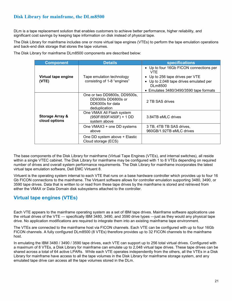
Disk Library for mainframe, the DLm8500
DLm is a tape replacement solution that enables customers to achieve better performance, higher reliability, and significant cost savings by keeping tape information on disk instead of physical tape.
The Disk Library for mainframe includes one or more virtual tape engines (VTEs) to perform the tape emulation operations and back-end disk storage that stores the tape volumes.
The Disk Library for mainframe DLm8500 components are described below:
Component Details specifications
Virtual tape engine (VTE)
Tape emulation technology consisting of 1-8 “engines”
• Up to four 16Gb FICON connections per VTE
• Up to 256 tape drives per VTE • Up to 2,048 tape drives emulated per
DLm8500 • Emulates 3480/3490/3590 tape formats
Storage Array & cloud options
One or two DD9800s, DD9500s, DD9300s DD6800s or DD6300s for data deduplication
2 TB SAS drives
One VMAX All Flash system (950F/850F/450F) + 1 DD system above
3.84TB eMLC drives
One VMAX3 + one DD systems above
3 TB, 4TB TB SAS drives, 960GB/1.92TB eMLC drives
One DD system above + Elastic Cloud storage (ECS)
The base components of the Disk Library for mainframe (Virtual Tape Engines (VTEs), and internal switches), all reside within a single VTEC cabinet. The Disk Library for mainframe may be configured with 1 to 8 VTEs depending on required number of drives and overall system performance requirements. The Disk Library for mainframe incorporates the latest virtual tape emulation software, Dell EMC Virtuent 8.
Virtuent is the operating system internal to each VTE that runs on a base hardware controller which provides up to four 16 Gb FICON connections to the mainframe. The Virtuent software allows for controller emulation supporting 3480, 3490, or 3590 tape drives. Data that is written to or read from these tape drives by the mainframe is stored and retrieved from either the VMAX or Data Domain disk subsystems attached to the controller.
Virtual tape engines (VTEs)
Each VTE appears to the mainframe operating system as a set of IBM tape drives. Mainframe software applications use the virtual drives of the VTE — specifically IBM 3480, 3490, and 3590 drive types —just as they would any physical tape drive. No application modifications are required to integrate them into an existing mainframe tape environment.
The VTEs are connected to the mainframe host via FICON channels. Each VTE can be configured with up to four 16Gb FICON channels. A fully configured DLm8500 (8 VTEs) therefore provides up to 32 FICON channels to the mainframe host.
In emulating the IBM 3480 / 3490 / 3590 tape drives, each VTE can support up to 256 total virtual drives. Configured with a maximum of 8 VTEs, a Disk Library for mainframe can emulate up to 2,048 virtual tape drives. These tape drives can be shared across a total of 64 active LPARs. While each VTE operates independently from the others, all the VTEs in a Disk Library for mainframe have access to all the tape volumes in the Disk Library for mainframe storage system, and any emulated tape drive can access all the tape volumes stored in the DLm.
22
Back-end storage
VTEs process the arriving mainframe tape volume and write it as a single file on the Disk Library for mainframe storage. Each mainframe tape is stored as a single file whose file name matches the tape VOLSER. This allows the virtual tape to be easily located and mounted in response to read or write requests, typically within one second.
All disk drives within the Disk Library for mainframe are protected with a RAID 6 configuration and hot spare drives for each RAID group.
When configured with deduplication storage, compression is turned off when writing to disk. This enables a higher level of data reduction for those applications that can benefit from deduplication. The deduplication storage capability can provide up to 20 PB of logical storage based on a mix of typical enterprise data (file systems, data bases, email and developer files).
In summary, the Disk Library for mainframe DLm 8500 supports Data Domain deduplication storage and VMAX storage. The use of deduplication storage is ideal for repetitive backup data, for example 3990 volume dumps from FDR, DFDSS and/or CA-DISK. Deduplication of repetitive backups can substantially increase the overall data reduction achieved within the Disk Library for mainframe configuration resulting in significant reduction in storage and transmission costs. VMAX storage is ideally suited for unique data types that require the robust replication feature set contained within SRDF. The Disk Library for mainframe is the only available virtual tape library solution that can concurrently support both deduplication and primary storage and dynamically direct tapes to the most appropriate storage on a tape by tape basis.
Disk Library for mainframe management and support
The Disk Library for mainframe works seamlessly with the mainframe host and does not require any mainframe-based code changes to operate. Additionally, clients do not need to change their production operations or production Job Control Language (JCL).
DLm can be managed using DFSMS functionality and supports all tape channel commands. Therefore DFHSM, backups, and other client applications continue to work without change. Additionally, these operations are no longer dependent on a specific tape drive range and tape processing is done at disk speed. This reduces the time it takes for recycle/recall operations to complete, often within seconds or minutes, as opposed to hours.
DLm enables customers to manage and query various status and state conditions including the following:
• Customers can perform specific actions on or retrieve information about the Disk Library for mainframe directly from the mainframe master console. Customers can easily retrieve information such as available space, configuration, scratch count, and more. Customers can use a web based application, DLm Console, to remotely log in, query and manage the Disk Library for mainframe online.
• Disk Library for mainframe supports Simple Network Management Protocol (SNMP), which provides automatic alerts to email accounts or other third-party management tools.
Support is also provided for Dell EMC Secure Remote Support (ESRS), which enables Dell EMC Customer Support to establish secure IP connectivity to the Disk Library for mainframe and remotely log in to the system for diagnosing and troubleshooting system issues. In addition, DLm supports Connect Dell EMC, which automatically sends alerts directly to Dell EMC Support.
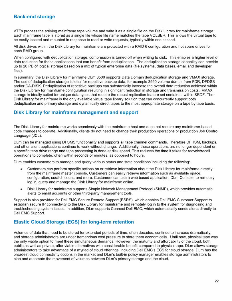
Elastic Cloud Storage (ECS) for long-term retention Volumes of data that need to be stored for extended periods of time, often decades, continue to increase dramatically, and storage administrators are under tremendous cost pressure to store them economically. Until now, physical tape was the only viable option to meet these simultaneous demands. However, the maturity and affordability of the cloud, both public as well as private, offer viable alternatives with considerable benefit compared to physical tape. DLm allows storage administrators to take advantage of a myriad of cloud offerings, including Dell EMC’s ECS for cloud storage. DLm has the broadest cloud connectivity options in the market and DLm’s built-in policy manager enables storage administrators to plan and automate the movement of volumes between DLm’s primary storage and the cloud.
23
Figure 13: DLm with Elastic Cloud Storage
A.R.M. YOUR DATACENTER WITH GDDR Geographically Dispersed Disaster Restart (GDDR) is a Dell EMC mainframe software product that automates business recovery following both planned outages and disaster situations, including the total loss of a data center. GDDR achieves this goal by providing Automation, Recovery, and Monitoring of many Dell EMC and third-party hardware and software products required for business restart, including VMAX primary storage and DLm virtual tape systems
GDDR is quite different from IBM GDPS in its design. GDDR employs a single control system per site for all topologies it supports. There are not different versions of GDDR tied to different replication technologies. GDDR supports both Dell EMC PowerMax, VMAX and DLm, and there is only one code base to support all Data Domain, VNX, PowerMax and VMAX replication technologies and topologies.
GDDR is also sold as an automation product, not as a services offering. While there are implementation services available and recommended to initially implement GDDR, ongoing services are not required for changes to the environment.
Because GDDR restarts production systems following disasters, it does not reside on the same servers that it is seeking to protect. GDDR resides on separate logical partitions (LPARs) from the host servers that run your application workloads.
GDDR is installed on a control LPAR at each site, unless tape-only DR is being managed, in which case GDDR can operated in a shared LPAR. Each GDDR node is aware of the other GDDR nodes through network connections between each site. This awareness allows GDDR to:
• Detect disasters
• Identify survivors
To achieve the task of business restart, GDDR automation extends well beyond the disk level and into the host operating system. It is at this level that sufficient controls and access to third-party software and hardware products exist to enable Dell EMC to provide automated recovery capabilities.
GDDR’s main activities include:
• Managing planned site swaps (workload, DASD, and /or virtual tape) between the primary and secondary sites and recovering the SRDF®/SQAR with AutoSwap™ environment. Note that tape processing is only supported in two-site mode.
24
• Managing planned site swaps (DASD only) between the primary and secondary sites and recovering the SRDF/SQAR with AutoSwap environment.
• Managing recovery from a single or dual planned or unplanned site outage in one region, with local SRDF/S protection established differentially between the recovery sites in another region. Out of region recovery is supported with cascaded or concurrent SRDF to an available out of region site.
• Managing the recovery of the SRDF environment and restarting SRDF/A in the event of an unplanned site swap.
• Active monitoring of the managed environment and responding to exception conditions.
• Reset/IPL of z/OS systems at remote site.
• Testing disaster recovery from TimeFinder local replicas at remote site.
• Testing disaster recovery from R2 at remote site.
GDDR successfully undertakes these activities by exploiting the following essential features designed into its architecture: a rules based expert system that gives GDDR situational awarenesss and survivor recognition, and the ability to dynamically build and execute recovery automation scripts automatically.
SUPPORTED BUSINESS CONTINUITY CONFIGURATIONS GDDR supports up to four ‘sites’ where a site is a physical location, housing CPU or DASD or both, where:
• Data Center DC1 is part of all supported GDDR configurations
• DC2 is a site connected to DC1 with SRDF/S
• DC3 is a site connected to DC1 with SRDF/A, either actively or as a recovery connection
• DC4 is a site connected to DC2 with SRDF/A, either actively or as a recovery connection
GDDR is available in the following configurations:
• SRDF/S with ConGroup - The 2-site SRDF/S with ConGroup configuration provides disaster restart capabilities at site DC2
• SRDF/S with AutoSwap - The 2-site SRDF/S with AutoSwap configuration provides for near-continuous availability through device failover between DC1 and DC2.
• SRDF/A - The 2-site SRDF/A configuration provides disaster restart capabilities at site DC3.
• SRDF/Star - The 3-site SRDF/Star configuration provides disaster restart capabilities at either DC2 or DC3. Concurrent and cascaded SRDF further minimize the DC3 recovery time objective.
• SRDF/Star with AutoSwap - The 3-site SRDF/Star with AutoSwap configuration provides for near-continuous availability through device failover between DC1 and DC2 as well as disaster restart capabilities at DC3. Concurrent and cascaded SRDF further minimize the DC3 recovery time objective.
• SRDF/SQAR with AutoSwap - The 4-site SRDF/SQAR with AutoSwap configuration provides for near-continuous availability through device failover between DC1 and DC2, within Region 1 as well as disaster restart capabilities at Region 2 with DC3 and DC4 located an extended geographical distance away from Region 1. SRDF concurrent or cascaded replication protects data originating from the recovery site following a primary region outage.
UNIVERSAL DATA CONSISTENCY: GDDR AND DISK LIBRARY FOR MAINFRAME (DLM) Dell EMC offers a unique data consistency solution for customers using both VMAX or PowerMax as their primary mainframe DASD and DLm with VMAX backend storage for their virtual tape library.
Dell EMC Mainframe-Enabler software includes Consistency Group (ConGroup) and Multi-Session Consistency (MSC) software packages that run on an IBM z/OS mainframe to provide point in time data consistency across CKD devices
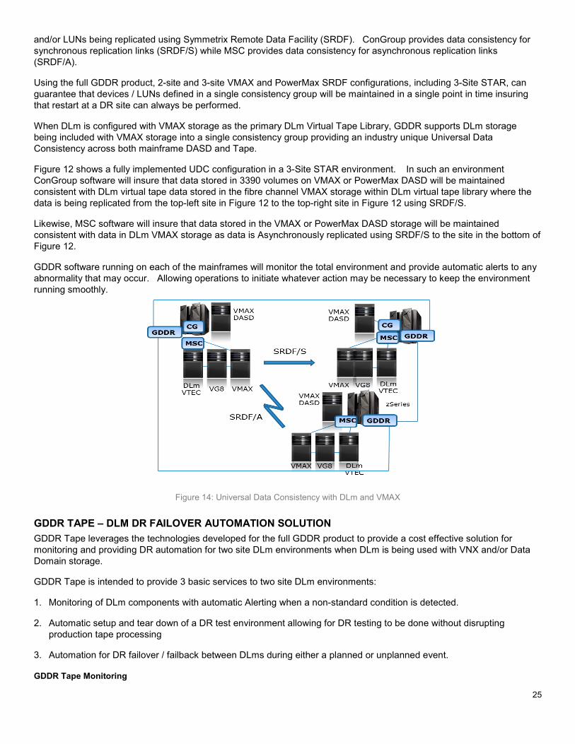
25
and/or LUNs being replicated using Symmetrix Remote Data Facility (SRDF). ConGroup provides data consistency for synchronous replication links (SRDF/S) while MSC provides data consistency for asynchronous replication links (SRDF/A).
Using the full GDDR product, 2-site and 3-site VMAX and PowerMax SRDF configurations, including 3-Site STAR, can guarantee that devices / LUNs defined in a single consistency group will be maintained in a single point in time insuring that restart at a DR site can always be performed.
When DLm is configured with VMAX storage as the primary DLm Virtual Tape Library, GDDR supports DLm storage being included with VMAX storage into a single consistency group providing an industry unique Universal Data Consistency across both mainframe DASD and Tape.
Figure 12 shows a fully implemented UDC configuration in a 3-Site STAR environment. In such an environment ConGroup software will insure that data stored in 3390 volumes on VMAX or PowerMax DASD will be maintained consistent with DLm virtual tape data stored in the fibre channel VMAX storage within DLm virtual tape library where the data is being replicated from the top-left site in Figure 12 to the top-right site in Figure 12 using SRDF/S.
Likewise, MSC software will insure that data stored in the VMAX or PowerMax DASD storage will be maintained consistent with data in DLm VMAX storage as data is Asynchronously replicated using SRDF/S to the site in the bottom of Figure 12.
GDDR software running on each of the mainframes will monitor the total environment and provide automatic alerts to any abnormality that may occur. Allowing operations to initiate whatever action may be necessary to keep the environment running smoothly.
Figure 14: Universal Data Consistency with DLm and VMAX
GDDR TAPE – DLM DR FAILOVER AUTOMATION SOLUTION GDDR Tape leverages the technologies developed for the full GDDR product to provide a cost effective solution for monitoring and providing DR automation for two site DLm environments when DLm is being used with VNX and/or Data Domain storage.
GDDR Tape is intended to provide 3 basic services to two site DLm environments:
1. Monitoring of DLm components with automatic Alerting when a non-standard condition is detected.
2. Automatic setup and tear down of a DR test environment allowing for DR testing to be done without disrupting production tape processing
3. Automation for DR failover / failback between DLms during either a planned or unplanned event.
GDDR Tape Monitoring
26
As discussed in DLm Overview section earlier in this white paper, a DLm solution is made up of a number of components. When DLm2100 is being used the solution may be as simple as 1 or 2 DLM2100s physically connected to a Data Domain storage controller, replicated to a remote Data Domain storage controller at another site.
DLM8100, on the other hand has multiple hardware components making up the solution. Minimally there are two (2) 10 Gigabit Ethernet switches used to connect Virtual Tape Engines (VTEs) to storage. There are two (2) 1 Gigabit Ethernet switches connecting the VTEs in a control network allowing administration and control of the environment. There are 1 to 8 VTE engines each with 2 FICON attachments and connections to the 10 Gig E switches, and there is 1 or 2 storage subsystems that may include multiple storage controllers / data movers.
Finally, there are replication links and services which are used to replicate data between DLMs in order to provide data protection to the overall two site environment.
GDDR Tape software runs as a started task in a production z/OS LPAR on the mainframes making up the two site environment. GDDR Tape monitors the storage, VTEs, switches, file systems, and replication links to insure operation of the solution.
GDDR Tape automatically alerts mainframe operations when a fault or error condition is detected in DLm environment. Providing operations staff the opportunity to take whatever corrective action deemed necessary based on the alert that has been raised
STORAGE MANAGEMENT SOFTWARE The following sections provide an overview of the Dell EMC z/OS mainframe storage management solutions.
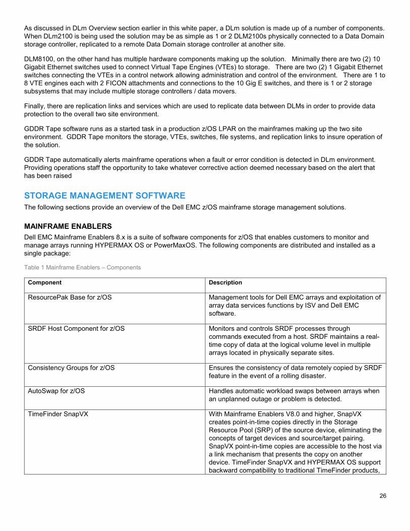
MAINFRAME ENABLERS Dell EMC Mainframe Enablers 8.x is a suite of software components for z/OS that enables customers to monitor and manage arrays running HYPERMAX OS or PowerMaxOS. The following components are distributed and installed as a single package:
Table 1 Mainframe Enablers – Components
Component Description
ResourcePak Base for z/OS Management tools for Dell EMC arrays and exploitation of array data services functions by ISV and Dell EMC software.
SRDF Host Component for z/OS Monitors and controls SRDF processes through commands executed from a host. SRDF maintains a real-time copy of data at the logical volume level in multiple arrays located in physically separate sites.
Consistency Groups for z/OS Ensures the consistency of data remotely copied by SRDF feature in the event of a rolling disaster.
AutoSwap for z/OS Handles automatic workload swaps between arrays when an unplanned outage or problem is detected.
TimeFinder SnapVX With Mainframe Enablers V8.0 and higher, SnapVX creates point-in-time copies directly in the Storage Resource Pool (SRP) of the source device, eliminating the concepts of target devices and source/target pairing. SnapVX point-in-time copies are accessible to the host via a link mechanism that presents the copy on another device. TimeFinder SnapVX and HYPERMAX OS support backward compatibility to traditional TimeFinder products,
27
including TimeFinder/Clone, TimeFinder VP Snap, and TimeFinder/Mirror.
Data Protector for z Systems (zDP™) With Mainframe Enablers V8.0 and higher, zDP is deployed on top of SnapVX. zDP provides a granular level of application recovery from unintended changes to data. zDP achieves this by providing automated, consistent point-in-time copies of data from which an application-level recovery can be conducted.
TimeFinder/Clone Mainframe Snap Facility Produces point-in-time copies of full volumes or of individual datasets.
TimeFinder/Mirror for z/OS Allows the creation of Business Continuance Volumes (BCVs) and provides the ability to ESTABLISH, SPLIT, RE-ESTABLISH and RESTORE from the source logical volumes.
TimeFinder Utility Conditions SPLIT BCVs by relabeling volumes and (optionally) renaming and recataloging datasets. This allows BCVs to be mounted and used
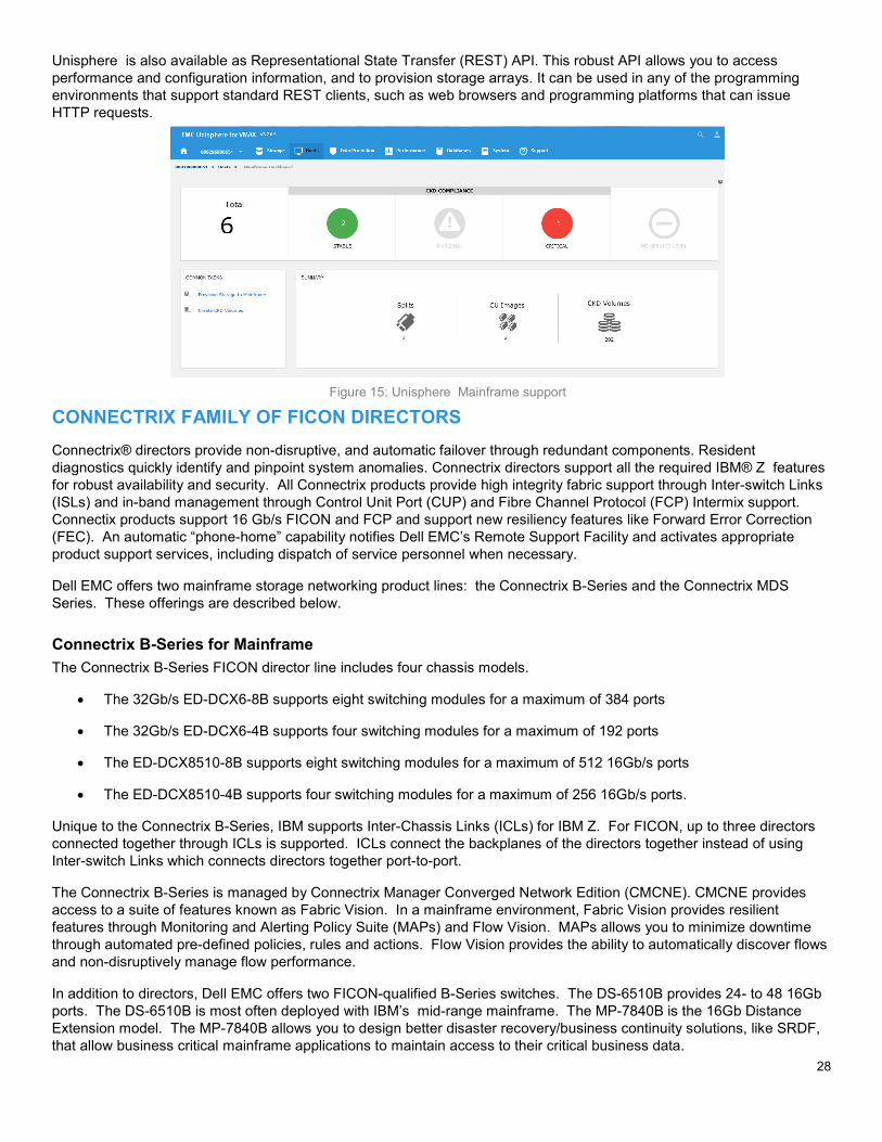
UNISPHERE Unisphere is an advanced Graphical User Interface (GUI) that provides a common Dell EMC user experience across storage platforms. Unisphere enables customers to easily provision, manage, and monitor VMAX and PowerMax environments.
With the release of HYPERMAX OS it is possible to run Unisphere as a Guest Operating system within the VMAX or PowerMax native Hypervisor. This option removes the need to an external management host to control and manage the VMAX or PowerMax array.
Unisphere for VMAX Version 8.2.0 introduced support for the creation, management, expansion, and deletion of CKD devices, through the use of the new Mainframe Dashboard. The Mainframe Dashboard provides a single place to monitor and manage configured splits, CU images and CKD volumes.
Unisphere offers big-button navigation and streamlined operations to simplify and reduce the time required to manage a data center; it also simplifies storage management under a common framework.
Unisphere 8.2 contains a number of task-oriented dashboards to make monitoring and configuring VMAX and PowerMax systems intuitive and easy.
The Storage Group Dashboard displays information about application storage groups and whether or not they are meeting their SLO requirements. Administrators can quickly navigate from this dashboard to gather more in-depth performance statistics.
28
Unisphere is also available as Representational State Transfer (REST) API. This robust API allows you to access performance and configuration information, and to provision storage arrays. It can be used in any of the programming environments that support standard REST clients, such as web browsers and programming platforms that can issue HTTP requests.
CONNECTRIX FAMILY OF FICON DIRECTORS Connectrix® directors provide non-disruptive, and automatic failover through redundant components. Resident diagnostics quickly identify and pinpoint system anomalies. Connectrix directors support all the required IBM® Z features for robust availability and security. All Connectrix products provide high integrity fabric support through Inter-switch Links (ISLs) and in-band management through Control Unit Port (CUP) and Fibre Channel Protocol (FCP) Intermix support. Connectix products support 16 Gb/s FICON and FCP and support new resiliency features like Forward Error Correction (FEC). An automatic “phone-home” capability notifies Dell EMC’s Remote Support Facility and activates appropriate product support services, including dispatch of service personnel when necessary.
Dell EMC offers two mainframe storage networking product lines: the Connectrix B-Series and the Connectrix MDS Series. These offerings are described below.
Connectrix B-Series for Mainframe The Connectrix B-Series FICON director line includes four chassis models.
• The 32Gb/s ED-DCX6-8B supports eight switching modules for a maximum of 384 ports
• The 32Gb/s ED-DCX6-4B supports four switching modules for a maximum of 192 ports
• The ED-DCX8510-8B supports eight switching modules for a maximum of 512 16Gb/s ports
• The ED-DCX8510-4B supports four switching modules for a maximum of 256 16Gb/s ports.
Unique to the Connectrix B-Series, IBM supports Inter-Chassis Links (ICLs) for IBM Z. For FICON, up to three directors connected together through ICLs is supported. ICLs connect the backplanes of the directors together instead of using Inter-switch Links which connects directors together port-to-port.
The Connectrix B-Series is managed by Connectrix Manager Converged Network Edition (CMCNE). CMCNE provides access to a suite of features known as Fabric Vision. In a mainframe environment, Fabric Vision provides resilient features through Monitoring and Alerting Policy Suite (MAPs) and Flow Vision. MAPs allows you to minimize downtime through automated pre-defined policies, rules and actions. Flow Vision provides the ability to automatically discover flows and non-disruptively manage flow performance.
In addition to directors, Dell EMC offers two FICON-qualified B-Series switches. The DS-6510B provides 24- to 48 16Gb ports. The DS-6510B is most often deployed with IBM’s mid-range mainframe. The MP-7840B is the 16Gb Distance Extension model. The MP-7840B allows you to design better disaster recovery/business continuity solutions, like SRDF, that allow business critical mainframe applications to maintain access to their critical business data.
Figure 15: Unisphere Mainframe support
29
Finally, Dell EMC embeds the Connectrix B-Series VDX-6740B in Dell EMC’s DLm for mainframe backup that allows you the ability to do both IP and Fibre Channel extension to replicate DLm data over distance in combination with the MP-7840B.
Connectrix MDS Series for Mainframe The Connectrix MDS Series includes two director models and one multi-purpose switch model. All three products support FICON.
• The MDS-9710 director model supports up to eight switching modules for a maximum of 384 16Gb/s ports
• The MDS-9706 director model supports up to four switching modules for a maximum of 192 16Gb/s ports.
• The MDS-9250i switch model provides distance extension with FCiP for mainframe environments.
The MDS Series also supports many FICON features including FICON Dynamic Routing, FICON Port Channels, full VSAN support and 10Gigabit Ethernet support for FCiP and distance extension.
Data Center Network Manager® (DCNM), the management tool for Connectrix MDS, optimizes the overall uptime and reliability of your data center infrastructure and helps improve business continuity. DCNM, automates provisioning, monitors and detects degradation, and provides faster problem resolution.
DATA MIGRATION WITH Z/OS MIGRATOR Dell EMC z/OS Migrator is a host-based data migration facility that migrates data from any vendor's storage array to a VMAX or PowerMax array without application downtime or disruption to business-continuity readiness. It can also be used to migrate data from one VMAX or PowerMax array to another. The migration can be done at either the volume or the dataset level. Dell EMC z/OS Migrator performs traditional volume migrations as well as host-based volume mirroring. Together, these capabilities are referred to as the Volume Mirror and Volume Migrator functions of z/OS Migrator.
In addition, z/OS Migrator can also migrate active mainframe datasets at the logical dataset (extent) level from one set of volumes to another, without any application downtime. This capability is referred to as logical migration, and z/OS Migrator can perform this migration in a non-disruptive manner to applications and business continuity.
Volume-level data migration facilities move logical volumes in their entirety. z/OS Migrator volume migration is performed on a track-for-track basis without regard to the logical contents of the volumes involved. Volume migrations end in a volume swap, which is entirely non-disruptive to any applications using the data on the volumes.
Frequently, however, it is advantageous to relocate datasets at a more granular level. So, in addition to volume migration, z/OS Migrator provides for logical migration, that is, the migration of individual datasets. In contrast to volume migration functions, z/OS Migrator performs dataset migrations with full awareness of the contents of the volume and the metadata in the z/OS system that describe the datasets on the logical volume.
z/OS Migrator enables users to:
• Introduce new storage subsystem technologies with minimal disruption of service.
• Reclaim z/OS UCBs by simplifying the migration of datasets to larger volumes (combining volumes).
• Facilitate data migration while applications continue to run and fully access data being migrated, eliminating application downtime usually required when migrating data.
• Eliminate the need to coordinate application downtime across the business, and eliminate the costly impact of such downtime on the business.
• Improve application performance by facilitating the relocation of poor performing datasets to lesser used volumes/storage arrays.
• Ensure all operating system metadata always accurately reflects the location and status of datasets being migrated.
30
SUMMARY Dell EMC provides a complete solution to mainframe primary and tape-based storage requirements. In addition to IBM channel and copy services compatibility, Dell EMC provide unique innovation offered by no other storage vendor, including PAV Optimizer, SnapVX and zDP. DLm, GDDR, and Connectrix complete the picture providing for elimination of physical tape with deduplication, automated recovery, and FICON SAN, respectively. Together, these products represent 25+ years of experience and billions of dollars in investment in order to satisfy the needs of modern mainframe data centers.