deliverable d3.1 functional network architecture and ... · bss business support system ... kpi key...
TRANSCRIPT

5G NORMA Deliverable D3.1
Dissemination level: Public Page 1 / 60
Project: H2020-ICT-2014-2 5G NORMA
Project Name:
5G Novel Radio Multiservice adaptive network Architecture (5G NORMA)
Deliverable D3.1
Functional Network Architecture and Securi-ty Requirements
Date of delivery: 31/12/2015 Version: v1.0
Start date of Project: 01/07/2015 Duration: 6 months

5G NORMA Deliverable D3.1
Dissemination level: Public Page 2 / 60
Document properties:
Document Number: H2020-ICT-2014-2 5G NORMA/D3.1
Document Title: Functional network architecture and security require-ments
Editor(s): Peter Rost, Nokia Networks
Authors: Diomidis Michalopoulos, Vinh van Phan, Ling Yu, Chris-tian Mannweiler, Peter Rost, Peter Schneider (Nokia Networks); Mark Doll, Bessem Sayadi (Alcatel-Lucent); Konstantinos Samdanis, Vincenzo Sciancalepore (NEC). Miguel A. Puente (Atos); Heinz Droste, Markus Breit-bach (Deutsche Telekom); Serban Purge (Orange); Ig-nacio Beberana (Telefonica); Alessandro Colazzo, Ric-cardo Ferrari (Azcom); Azad Ravanshid (Nomor Re-search); Ade Ajibulu (Real Wireless); Shreya Tayade (TU Kaiserslautern); Marco Gramaglia, Albert Banchs (Universidad Carlos III Madrid); Stan Wong, Oliver Hol-land (King’s College London)
Contractual Date of Delivery: 31/12/2015
Dissemination level: PU
Status: Final version
Version: 1.0
File Name: 5G_NORMA_D3.1.docx
Revision History
Revision Date Issued by Description
1.0 Dec 2015 5G NORMA WP3 Final version
Abstract
This report provides a comprehensive list of quantitative and qualitative requirements for the
5G NORMA architecture, including security and functional requirements. Based on these require-
ments, key technology enablers are described which are necessary for a 5G architecture. In order to
integrate these technologies, the preliminary 5G NORMA reference architecture is introduced. It is
detailed through four distinct views which relate the two main functional requirements, i.e. mobile
network multi-tenancy, and multi-service and context-aware adaptation and allocation of mobile
network functions, with the key technology enablers Software-defined mobile network control, adap-
tive composition and allocation of network functions, and joint optimization of mobile access and
core. Using these four different views, the architecture is discussed and its requirements are further
detailed. Finally, this report provides a detailed description of the validation process of the
5G NORMA architecture design.
Keywords
Mobile network architecture, functional requirements, security requirements, software defined mo-
bile network, functional decomposition, joint optimization of mobile access and core, evaluation and
validation process

5G NORMA Deliverable D3.1
Dissemination level: Public Page 3 / 60
Table of Contents
1 Introduction......................................................................................................................... 10 1.1 Background and Scope ................................................................................................ 10
1.2 Key Contributions ........................................................................................................ 10
2 State of the Art and Related Work in Progress ............................................................... 11 2.1 Mobile Network Architecture ...................................................................................... 11
2.1.1 NGMN .................................................................................................................... 11
2.1.2 EU FP7 iJOIN ......................................................................................................... 15
2.1.3 EU FP7 METIS ...................................................................................................... 17
2.1.4 3GPP ....................................................................................................................... 20
2.2 Software Defined Networking and Open Network Foundation................................... 22
2.3 ETSI Network Functions Virtualization ...................................................................... 24
3 Requirements on the 5G Mobile Network Architecture ................................................. 25 3.1 Scenarios and Business Models ................................................................................... 25
3.2 Flexibility, Scalability, and Context-Awareness ......................................................... 27
3.3 Security Requirements ................................................................................................. 28
3.4 Operational Requirements for 5G Architecture ........................................................... 29
3.4.1 Mobile Network Multi-Tenancy ............................................................................. 29
3.4.2 Multi-Service and Context-Aware Adaptation and Allocation of Mobile
Network Functions.................................................................................................. 30
4 5G NORMA Key Enablers and Reference Architecture ................................................ 31 4.1 Key Innovations and Enablers ..................................................................................... 31
4.1.1 Software Defined Mobile Network Control and Orchestration .............................. 32
4.1.2 Adaptive Composition and Allocation of Mobile Network Functions ................... 33
4.1.3 Joint Optimization of Mobile Access and Core ...................................................... 35
4.2 Reference Architecture and its Views ......................................................................... 35
5 5G NORMA Architectural Views ..................................................................................... 38 5.1 Resource View ............................................................................................................. 38
5.1.1 Deployment Types .................................................................................................. 38
5.1.2 Hardware Resources ............................................................................................... 39
5.1.3 Business Logic Software Resources ....................................................................... 40
5.2 Functional View ........................................................................................................... 41
5.3 Deployment View ........................................................................................................ 46
5.4 Topological and Physical View ................................................................................... 48
6 Architecture Design Validation ......................................................................................... 49 6.1 Approach and Motivation ............................................................................................ 49
6.2 Evaluation Criteria ....................................................................................................... 50
6.3 Evaluation Concept ...................................................................................................... 51
6.3.1 PoC Demonstrators ................................................................................................. 51
6.3.2 Economic Evaluation .............................................................................................. 51
6.3.3 Protocol Verification .............................................................................................. 52
6.3.4 Protocol Overhead Analysis ................................................................................... 52
6.4 Evaluation Scenarios.................................................................................................... 53
7 Summary and Conclusions ................................................................................................ 57
8 References ............................................................................................................................ 58

5G NORMA Deliverable D3.1
Dissemination level: Public Page 4 / 60
List of Figures
Figure 2-1: Technology trends identified by NGMN [2] ............................................................ 12
Figure 2-2: NGMN 5G architecture [2] ...................................................................................... 14
Figure 2-3: Logical architecture as proposed by EU FP7 iJOIN................................................. 15
Figure 2-4: Functional architecture as proposed by EU FP7 iJOIN ............................................ 16
Figure 2-5: RANaaS platform as proposed by EU FP7 iJOIN .................................................... 17
Figure 2-6: Main building blocks of METIS 5G architecture. .................................................... 18
Figure 2-7: Logical orchestration & control architecture of METIS 5G system ......................... 19
Figure 2-8: METIS E2E reference network ................................................................................ 20
Figure 2-9: 3GPP architectures for network sharing; (a) MOCN, (b) GWCN............................ 21
Figure 2-10 ONF-SDN Architecture ........................................................................................... 22
Figure 2-11: ETSI NFV MANO architecture.............................................................................. 24
Figure 3-1: Service drivers for 5G mobile network development ............................................... 26
Figure 4-1: Layers for function (de)composition and (re)allocation ........................................... 34
Figure 4-2: The four architecture views as considered by 5G NORMA ..................................... 36
Figure 5-1: 5G NORMA resource view ...................................................................................... 38
Figure 5-2: Preliminary 5G NORMA functional reference architecture ..................................... 41
Figure 5-3: Example control and data layer employing LTE-like functional blocks .................. 45
Figure 5-4: Example MANO deployment view .......................................................................... 46
Figure 5-5: Fully distributed RAN (top) and cloudified CRAN (bottom) deployment............... 47
Figure 5-6: 5G NORMA topology view on architecture ............................................................ 48
Figure 6-1: Architecture design and design validation within 5G NORMA ............................... 49

5G NORMA Deliverable D3.1
Dissemination level: Public Page 5 / 60
List of Tables
Table 6-1 : Importance of requirement groups for the selected use cases ................................... 54
Table 6-2: Requirement groups – demos mapping ..................................................................... 55
Table 6-3: Demo scenarios overview .......................................................................................... 56

5G NORMA Deliverable D3.1
Dissemination level: Public Page 6 / 60
List of Acronyms and Abbreviations
Acronym Description
3GPP Third Generation Partnership Project
5G NORMA Novel Radio Multiservice Network Adaptive Architecture
A-CPI Application-Controller Plane Interface
AI Air Interface
API Application Programming Interface
BB Building Block
BS Base Station
BSS Business Support System
CAPEX Capital Expenditure
CME Central Management Entity
cMTC Critical Machine Type Communication
CNE Core Network Element
CoMP Cooperative Multipoint
CRAN Centralized Radio Access Network
D2D Device-to-Device
D-CPI Data-Controller Plane Interface
DPI Deep Packet Inspection
DSP Digital Signal Processor
E2E End-to-End
EC European Commission
EM Element Management
eNB Enhanced Node B
EPC Evolved Packet Core
ETSI European Telecommunications Standards Institute
FE Functional Element
FPGA Field Programmable Gate Array
GUI Graphical User Interface
GWCN Gateway Core Network
H2020 Horizon 2020
HSS Home Subscriber Server
HT Horizontal Topic
IaaS Infrastructure as a Service
ICT Information and Communication Technologies
IE Information Element
5G NORMA Deliverable D3.1
Dissemination level: Public Page 7 / 60
IMS IP-based Multimedia Services
iNC iJOIN Network Controller
InP Infrastructure Provider
iRPU iJOIN Radio Processing Unit
iSC iJOIN Small Cell
KPI Key Performance Indicator
MAC Medium Access Control
MANO Management and Orchestration
MANO-F Management and Orchestration Function
MBB Massive Broadband
MCS Modulation and Coding Scheme
MME Mobility Management Entity
mMTC Massive Machine Type Communication
MOCN Multi Operator Core Network
MSC Message Sequence Chart
MTC Machine Type Communication
NaaS Network as a Service
NEM Network Element Manager
NF Network Function
NF-FG Network Function Forwarding Graph
NFV Network Function Virtualization
NFVI Network Function Virtualization Infrastructure
NFVO Network Function Virtualization Orchestrator
NGMN Next Generation Mobile Networks Alliance
ONF Open Network Foundation
OPEX Operational Expenditure
OS Operating System
OSS Operation Support System
OTT Over The Top
PA Power Amplifier
PCRF Policy and Charging Rules Function
PDCP Packet Data Convergence Protocol
PDN Packet Data Network
PDU Packet Data Unit
P-GW Packet Gateway
PLMN Public Land Mobile Network
PoC Proof of Concept
5G NORMA Deliverable D3.1
Dissemination level: Public Page 8 / 60
QoE Quality of Experience
QoS Quality of Service
RAN Radio Access Network
RANaaS RAN as a Service
RAT Radio Access Technology
RG Requirement Group
RISC Reduced Instruction Set Computer
RLC Radio Link Control
RNE Radio Network Element
RNM Radio Node Management
RRC Radio Resource Control
SBI Southbound Interface
SDMC Software Defined Mobile Network Control
SDMC+O Software Defined Mobile Network Control and Orchestration
SDN Software Defined Networking
S-GW Serving Gateway
SoC System on Chip
SON Self-Organising Networks
TeC Technology Components
UDN Ultra-Dense Network
UE User Equipment
V2X Vehicle-to-Anything
veNB Virtual eNB
VIM Virtualized Infrastructure Manager
VM Virtual Machine
VN Virtual Network
VMNO Virtual Mobile Network Operator
VNF Virtual Network Function
VNFM Virtual Network Function Manager
WAN Wide Area Network
WP Work Package

5G NORMA Deliverable D3.1
Dissemination level: Public Page 9 / 60
Definitions
Slice A network slice (instance) is a collection of (mobile) network func-
tion instances including their required resources necessary to oper-
ate an end-to-end (self-contained) logical mobile network.
5G NORMA protocol The protocol to convey information over a reference point. Infor-
mation and concrete protocol characteristics are reference point
dependent.
Controller A network function in the control layer that dynamically influences
the behaviour of a set of network function instances through their
fast reconfiguration.
Function chain A function chain (in the context of network functions) refers to a
directed graph that describes how individual network functions are
logically interconnected.
Infrastructure pro-
vider
The business entity providing physical and virtual network re-
sources like memory, compute, storage or networking to service
provider(s) (cf. section 5.1.2).
Interface/Reference
point
A reference point is the point of connectivity between two network
functions within the function chain. It unambiguously identifies the
characteristics of that interconnection.
Manager A function of the management and orchestration layer that manag-
es specific aspects of network function instances like life cycle or
configuration.
Network function A physical or virtual function (type) in the control or data layer.
Orchestrator The orchestrators generate a suitable function chain in a network
slice that provides the service requested by the tenant.
Policy A policy is a (set of) rule(s) to guide the orchestrators’ decisions.
Library A database holding software resources like virtual network func-
tions, MANO functions or network services, including their de-
scriptions to enable orchestration (cf. section 5.1.3).
Service A component of the portfolio of choices offered by service provid-
ers to a user, i.e., a functionality offered to a user. The user can be
an end-user, an enterprise or a tenant. Examples are voice, messag-
ing, broadband internet or machine type communication.
Service provider The business entity providing service(s) to its tenant(s) by utilizing
resources from infrastructure provider(s).
Service template The service template describes the service properties, e.g. the end-
to-end latency it demands, and a suitable function chain that im-
plements this service.
Tenant The business entity requesting and using a service from a service
provider.
5G NORMA Deliverable D3.1
Dissemination level: Public Page 10 / 60
1 Introduction
1.1 Background and Scope
5G NORMA aims at designing a novel 5G mobile network architecture which provides a higher
degree of flexibility in order to accommodate use cases which are going to be relevant for 5G
mobile network deployments. Since it is not possible to foresee all future use cases with proba-
bly diverging requirements, the architecture must be sufficiently flexible to integrate and adapt
to these use cases. The increased level of flexibility is achieved through “multi-service and con-
text-aware adaptation of network functions” and “mobile network multi-tenancy” enabled by
novel concepts of “adaptive (de)composition and allocation of mobile network functions”,
“software-defined mobile network control”, as well as “joint optimization of mobile access and
core network functions.”
The 5G NORMA architecture and therefore the scope of this document covers mobile access
and mobile core functionalities. In order to understand the needs for further improvement of
mobile network architectures, we first explore the state of the art in Section 2. This state of the
art analysis defines the scope of our work which builds upon the results provided by the projects
EU FP7 iJOIN and EU FP7 METIS. 5G NORMA builds upon the architectural definitions in
3GPP including radio access and core network entities. Furthermore, the scope includes the
novel area of software defined networking and network function virtualization.
The definition of the architecture relies mainly on the definition of requirements which may be
expressed in quantitative and qualitative terms. An overview of the underlying requirements of
the architecture is provided in Section 3 taking into account relevant scenarios and use cases,
qualitative requirements such as flexibility, security requirements, and functional requirements.
Building upon these requirements, key technology enablers are defined which must be support-
ed and integrated by the mobile network architecture. In the case of the 5G NORMA architec-
ture, these are software defined mobile network control and orchestration, adaptive composition
and allocation of mobile network functions, and joint optimization of mobile access and core, as
further described in Section 4. These key enablers are then integrated into the 5G NORMA ar-
chitecture and can be considered from different angles, or architecture views, which are detailed
in Section 5.
Finally, this document introduces and details the architecture design validation in Section 6. The
validation concept details the approach and main objectives of the validation process, which
needs to address both quantitative and qualitative metrics. We further define different means of
validation including demonstrators, simulations, and analytical tools. Finally, the document
provides an overview of evaluation scenarios.
1.2 Key Contributions
The key contributions of this document include the definition of architecture requirements
which are used to design the 5G NORMA mobile network architecture. This includes quantita-
tive and qualitative requirements, which are important to integrate the expected diversity of use
cases and services in the future 5G mobile network.
We further introduce the first, preliminary 5G NORMA mobile network architecture and four
distinct views on the architecture. These different views reflect different aspects of a mobile
network and reveal different important interaction and functionality of the mobile network ar-
chitecture. These different views are applied throughout the project in order to develop and op-
timize functionality.

5G NORMA Deliverable D3.1
Dissemination level: Public Page 11 / 60
Finally, the document provides a detailed validation concept which does not solely focus on
individual use cases but it provides a holistic view by means of overarching scenarios integrat-
ing multiple use cases.
2 State of the Art and Related Work in Pro-gress
While 5G NORMA aims to design a new architecture based on novel concepts, some of the
enabling technologies upon which it relies have received substantial attention so far. In the fol-
lowing, we review the main contributions that have been performed by standardization bodies,
other projects and academic literature recently. All these contributions can be largely classified
into three different topic areas: (i) mobile network architecture, (ii) Software Defined Network-
ing (SDN), and (iii) Network Function Virtualization (NFV).
Two of the precursor projects of 5G NORMA, namely EU FP7 METIS and EU FP7 iJOIN,
have devoted significant efforts to devise novel architectures that enable some of the features
pursued by 5G NORMA. These are considered as starting points by 5G NORMA, which will
build on the results of these previous projects and extend them to build an architecture that
comprises some of the building blocks coming from both projects and extend them to design a
comprehensive architecture. Some additional contributions to the definition of mobile architec-
tures have also been provided by standards or similar organizations, such as the Next Genera-
tion Mobile Networks Alliance (NGMN) and the Third Generation Partnership Project (3GPP).
NGMN has defined a set of requirements and high-level design criteria, which were already
used as guidelines by 5G NORMA for the definition of relevant requirements and use cases in
[18]. It is worth mentioning that many of the 5G NORMA partners are actively involved in
NGMN. Furthermore, 5G NORMA has a clear plan to provide input to Third Generation Part-
nership Project (3GPP) as well despite the fact that 3GPP focuses rather on near-term develop-
ment.
As for SDN, the work undergoing at Open Network Foundation (ONF) has many similarities
with the Software Defined Mobile Network Control (SDMC) concept proposed by 5G NOR-
MA. Indeed, new ONF extensions aim to use the spirit of SDN to provide flexibility in the im-
plementation of mobile network functions (NFs) other than routing and forwarding, which is
precisely the goal of 5G NORMA. The 5G NORMA and ONF efforts are parallel activities in
terms of timing, and a number of partners involved in 5G NORMA are actually pushing the
same ideas at ONF. This provides a very good framework to place 5G NORMA results in
standards and thus maximising their impact.
Finally, the European Telecommunications Standards Institute (ETSI) has defined a NFV archi-
tecture which is a key enabler for the flexible function (de)composition and allocation concept
of 5G NORMA. 5G NORMA plans to define an architecture as close as possible to ETSI NFV.
2.1 Mobile Network Architecture
2.1.1 NGMN
In February 2015, NGMN has published a 5G White Paper [2]. Therein, NGMN describes its
vision of the 5G business environment expected to emerge in 2020 and the following decade. It
identifies demands and business needs of the envisioned services and analyses how technology
and architecture can meet these requirements.

5G NORMA Deliverable D3.1
Dissemination level: Public Page 12 / 60
2.1.1.1 Requirements on 5 G networks and enabling technologies
In [2], the identified 5G requirements have been compared to the capabilities of a baseline 4G
system according to 3GPP Release 12. This comparison has shown the need for improvements
in three main areas:
- 4G network capabilities cannot meet the demands of future services. Many user and
system performance parameters, e.g. data rate, minimum end-to-end latency and con-
nection density, need to improve substantially.
- Today’s networks lack operational sustainability. The 4G core network architecture
consists of many dedicated network entities, making the network architecture complex
and difficult to scale and manage. On the other hand, many operations and maintenance
processes still require manual work and site visits. 5G shall lower the operational costs,
both in terms of procedural, organizational, and administrative effort and of energy con-
sumptions.
- Greater flexibility and business agility are essential to enable new business models.
NGMN has spotted several ongoing technology trends that will contribute to achieve these im-
provements. Figure 2-1 illustrates these trends and how they relate to the three main areas, men-
tioned above.
Figure 2-1: Technology trends identified by NGMN [2]
NGMN has collected a list of technology building blocks and analysed their benefits and ma-
turity. This list can be found in the annex of [2]. From the perspective of 5G NORMA, several
technology building blocks are particularly interesting:
- Flexible split of radio access network (RAN) functions among network nodes
- Software Defined Networking
- Smart Edge Node (a node, e.g. a base station, that can actively carry out some of the
core network functionalities or additional services such as caching)
- Virtualization of the mobile core network

5G NORMA Deliverable D3.1
Dissemination level: Public Page 13 / 60
- Virtualized Cloud-RAN (C-RAN)
- Enhanced multi-operator network sharing
- Enhanced multi-radio access technology (RAT) coordination
- Context-aware and user centered network
Apparently, all these technologies are in line with 5G NORMA’s innovative enablers adaptive
(de)composition and allocation of mobile NFs, SDMC, and joint optimization of mobile access
and core NFs. These technologies are further in line with 5G NORMA’s innovative functionali-
ties mobile network multi-tenancy, and multi-service- and context-aware adaptation of NFs.
They all relate to NFV and SDN, and according to Figure 2-1, they are expected to improve
operational sustainability and business agility.
2.1.1.2 Network Slicing
In the analysis of business demands and service requirements, it has turned out that services
may have significantly different requirements on the network. To meet these requirements and
still exploit the benefits of a common network infrastructure, NGMN promotes the concept of
network slicing: According to NGMN, a “network slice (5G slice) supports the communication
service of a particular connection type with a specific way of handling the C-and U-plane for
this service. To this end, a 5G slice is composed of a collection of 5G network functions and
specific RAT settings that are combined together for the specific use case or business model”
[2]. Therefore, a network slice is a dedicated, logical network for a single tenant or a specific
application. It is understood as end-to-end network, covering NFs running in software on central
or edge cloud nodes as well as dedicated radio nodes, the transport network between nodes, and
possibly the 5G devices used by the customers. The service provided by a network slice is spe-
cifically adapted to the demands of the tenant or the application, which implies that C- and U-
plane for this service are handled in a specific way. Ideally, a network slice contains all neces-
sary functionality for this service but avoids all other functionality, thereby minimizing its inter-
nal complexity.
Slices are mutually isolated, e.g. access to data carried or stored within another slice is not per-
mitted. Nevertheless, since slices are dedicated logical, not dedicated physical networks, multi-
ple slices can share the same infrastructure resources and the same physical NF. This will im-
prove the utilization of the infrastructure equipment, reduce energy costs and thus improve the
operational sustainability of the network equipment. Alternatively, infrastructure resources can
also be assigned to a dedicated slice for exclusive usage, when needed by the application or
requested by a tenant, e.g., in the case of mission-critical communications.
2.1.1.3 Architecture
NGMN’s proposed 5G architecture uses the structural separation of hardware and software
achieved by NFV methods and the programmability enabled through SDN concepts to offer
tenant- or application-specific network slices on a shared infrastructure. This architecture is
shown in Figure 2-2.

5G NORMA Deliverable D3.1
Dissemination level: Public Page 14 / 60
Figure 2-2: NGMN 5G architecture [2]
The NGMN 5G architecture comprises three layers and a management entity:
- The infrastructure resources layer comprises all physical network resources of a fixed-
mobile converged network, i.e. cloud nodes, networking nodes together with their asso-
ciated links, access nodes and 5G devices. The cloud nodes offer processing, network-
ing as well as storage capabilities and can be located in the center as well as on the edge
of the network. The 5G devices comprise terminal devices as well as data forwarding
devices, e.g. relays, hubs, or routers. It is expected that these devices and their capabili-
ties are also configurable. The physical resources are exposed to the business enable-
ment layer and can be accessed and configured by the management and orchestration
entity.
- The business enablement layer deals with the functions that are executed on the physi-
cal resources provided by the infrastructure layer. It comprises a library of functions re-
quired within a network, including functions realized by software modules that can be
retrieved from the repository to the desired location, and related configuration parame-
ters. Selection of the appropriate functions for a particular service, their arrangement
and configuration is done dynamically by the end-to-end (E2E) management and or-
chestration entity.
- The business application layer consists of specific applications or services of the mobile
network operator or tenant. On this layer, network slices can be created by the E2E
management and orchestration entity, and applications can be mapped to network slices.
- The E2E management and orchestration entity configures all three layers according to
demands of the requested service or business model and supervises them during
runtime. This includes defining the network slices, chaining the relevant modular NFs
and mapping them onto the infrastructure equipment. It also includes resource manage-
ment and scaling the capacity of functions and managing their geographic distribution.
NGMN expects that this entity will build on technologies designed in the framework of
by NFV, SDN, or self-organising networks (SON) concepts.

5G NORMA Deliverable D3.1
Dissemination level: Public Page 15 / 60
2.1.2 EU FP7 iJOIN
The EU FP7 project iJOIN1 has been a collaborative project which finished in April 2015. The
scope of this project was limited to small-cell networks where small-cells are connected through
heterogeneous backhaul to the core network. An essential part of this project was the quantita-
tive and qualitative analysis of the impact of non-ideal backhaul technology on the deployment
and performance of small-cell networks. In particular, the objective has been to investigate the
applicability of partial RAN centralisation as well as the use of commodity hardware to process
RAN functionality.
Due to the project size, iJOIN was strongly focusing on particular technologies, e.g. iJOIN pro-
posed an evolutionary path for 3GPP LTE and did not introduce novel LTE functionality but
rather applied and extended existing functions. This is in strong contrast to 5G NORMA which
aims for a clean-slate approach which may break with the existing 3GPP LTE architecture.
iJOIN further focused on the RAN and did not consider core NFs, compared to 5G NORMA
which considers both mobile core and RAN functions. Furthermore, iJOIN assumed digital sig-
nal processor (DSP) based processing platforms at radio access points and commodity hardware
based processing platforms at the central processor [3]. Finally, similar to 5G NORMA, iJOIN
investigated SDN based network control in order to optimize jointly radio access and backhaul
network operation [4][5].
J2
Figure 2-3: Logical architecture as proposed by EU FP7 iJOIN
1 http://www.ict-ijoin.eu

5G NORMA Deliverable D3.1
Dissemination level: Public Page 16 / 60
The first main architecture result is shown in Figure 2-3 which is the logical architecture as pro-
posed by iJOIN [5]. The proposed architecture did not break with the 3GPP LTE architecture
but rather introduced two interfaces, J1 and J2, which allow for a seamless integration of the
iJOIN technologies. Existing interfaces, i.e. S1 and X2, were not modified in order to maintain
legacy compliance.
WP3(MAC/RRM)
WP2(PHY)
WP4
(Network Mgmt/Control)
Estim
ate
d U
E d
ata
Estim
ate
d ch
an
ne
l
UE
da
ta
RR
M in
form
ati
on
(M
ap
)
Estimated BH load
Estimated BH parameters
RAN & BH configuration
BH measurements
MA
C in
form
ati
on
(M
CS)
RAN & BH configuration
BH measurements
BH routing table
U/C plane setup
U/C plane setup
WP4
iNC
NEO
AMM
TEEM
MM
RAC
iOpenFlow Controller
NMM
Path update request (re-route
due to congestion)
Path update request
(to switch off nodes)
RAC subscribedevents
Path related
actions
Path update request
(PoA change, Anchor reassignment)
TEEM subscribed events
NEO subscribedevents
AMM subscribedevents
Configure iOpenflow actions
Configure iOpenflow measurements
Measurement
Requests/Results
Conflict Resolution
Congestion related actions
Energyrelatedactions
Load Balancing request (due to Congestion)
Load Balancing request
(due to Energy)
a) Functional architecture
iNC
NEO
AMM
TEEM
MM
RAC
iOpenFlow Controller
NMM
Path update request
(to switch off nodes)
Path related
actions
Path update request
(PoA change , Anchor reassignment)
TEEM subscribedevents
Configure iOpenflow actions
Configure iOpenflow measurements
Measurement
Requests/Results
Conflict Resolution
Congestionrelated actions
Load Balancing request (due to Congestion)
Load Balancing request
(due to Energy)
b) iJOIN Network Controller
Figure 2-4: Functional architecture as proposed by EU FP7 iJOIN

5G NORMA Deliverable D3.1
Dissemination level: Public Page 17 / 60
Figure 2-4b) details the components of the iJOIN Network Controller (iNC) which is based on
the SDN concept and allows for joint optimization of mobile access network and backhaul net-
work operation [7][8][9]. The main purpose of the functional architecture has been to identify
the main components which are relevant for the partial centralization of small-cells over hetero-
geneous backhaul, to describe the interaction of these components, and to derive the necessary
control and management mechanisms.
RANaaS
RANaaS Manager/Orchestrator
S1/X2
Rv
RAN OAM
veNB
J1
N iSCs
iJOIN veNB controller
RAN functional
split realization
? iRPU
J3
iNCX2
M iRPUs
NF Virtualization
Infrastructure
Figure 2-5: RANaaS platform as proposed by EU FP7 iJOIN
Finally, the iJOIN project derived a detailed proposal for the centralized platform, which was
named RAN as a service (RANaaS) platform. The concept is illustrated in Figure 2-5 and the
main component of this concept is the virtual eNodeB (veNB) which is composed of physical
radio access points (here: iJOIN Small Cells, iSCs) and iJOIN radio processing units (iRPUs),
and controlled by a veNB controller. The veNB allows for encapsulating the processing divided
across remote and central site while maintaining standardized interfaces (e.g. X2) towards other
veNB or eNB, as well as the core network (e.g. S1). In [4] and [5], this concept is further de-
tailed and compared with the ETSI NFV architecture.
2.1.3 EU FP7 METIS
The EU FP7 project METIS2 [29] presents its architecture description from different viewpoints
as well. First, a functional architecture is presented that may lay a foundation for development
of first novel 5G NFs. It is based on functional decomposition of most relevant 5G technology
components. The logical orchestration and control architecture depicts the realization of flexibil-
ity, scalability and service orientation needed to fulfil diverse 5G requirements. Finally, a third
viewpoint reveals deployment aspects and function placement options for 5G.
2.1.3.1 Functional Architecture
Figure 2-6 illustrates the main building blocks (BBs) of the functional architecture identified by
METIS. Each main BB can be hierarchically split into a number of sub-BBs. These sub-BBs
can be “common BBs,” containing functionalities required for more than one Horizontal Topic
(HT) concept, and “HT-specific BBs,” which are essential for enabling a single HT concept. In
2 http://www.metis2020.com

5G NORMA Deliverable D3.1
Dissemination level: Public Page 18 / 60
order to make system and architecture development more clearly arranged the METIS architec-
ture integrated 5 less complex sub concepts that are denoted as “Horizontal Topics”. Each sub-
BB is finally described through a set of more fine granular Functional Elements (FEs) with each
FE performing an inherently consistent logical task. FEs have been derived by functional de-
composition of prioritized technology components (TeCs) developed in METIS [10]. Notably, a
TeC comprises a specific methodology, algorithm, module or protocol enabling certain system
features and contributing to the fulfillment of specific technical requirements. It has also to be
noted that METIS is primarily focusing on the RAN part, so not all components required to
operate a 5G system are covered.
Figure 2-6: Main building blocks of METIS 5G architecture.
The functional architecture can be decomposed into:
- Central Management Entities (CMEs), containing BBs that cover network over-
arching functionalities which are not specific for certain HTs and use cases or sce-
narios. Typical examples are Context Management and Spectrum Management.
These BBs are usually more centrally arranged. However, depending on the use
case, a partially distributed realization might be possible, as well.
- Radio Node Management (RNM) containing BBs that provide radio functionali-
ties that usually affect more than one radio node and that are not HT-specific. Ex-
emplary functions are Long-/Short-Term Radio Resource & Interference Manage-
ment, Mobility Management, Radio Node Clustering & (De-) Activation, and D2D
Device Discovery & Mode Selection. In principle those functions will be deployed
at medium network layers (e.g., at dedicated Cloud-RAN nodes [6]). The interface
requirements between FEs that are mapped to those BBs (especially the air inter-
face sub-BBs) have strong impact on the function placement.
- Air Interface (AI) including BBs that are directly related to air interface function-
alities of radio nodes and devices. It comprises HT-specific as well as common
BBs. Examples are AI enablers for ultra-dense networks (UDNs) or for different
types of machine type communication (MTC) applications.
- Reliable Service Composition represents a central C-Plane functionality with in-
terfaces to all other main BBs. It is used for availability evaluation and provision-
ing of ultra-reliable radio links which can be applied for novel service types requir-
ing extremely high reliabilities in message data transfer or extreme low latencies,
e.g., industrial environments, eHealth, or V2X (vehicle-to-anything) communica-
tion.

5G NORMA Deliverable D3.1
Dissemination level: Public Page 19 / 60
2.1.3.2 Logical Orchestration & Control Architecture
The METIS 5G architecture development was driven by three key aspects: flexibility, scalabil-
ity, and service-oriented management. The envisioned logical orchestration & control architec-
ture (see Figure 2-7) is based on usage of upcoming architectural trends, such as SDN and NFV.
It will provide the necessary flexibility for realizing efficient integration and cooperation of FEs
according to the individual service needs as well as future evolution of existing cellular and
wireless networks [11][12][2].
Figure 2-7: Logical orchestration & control architecture of METIS 5G system
NFs derived from FEs are flexibly deployed and instantiated by the 5G Orchestrator, which
consists of NFV Orchestrator, Virtual NF (VNF) Manager and Virtualized Infrastructure Man-
ager [13] as well as their extensions Service-oriented Function Processing Manager and Service-
oriented Topology Manager. It is responsible for managing all VNFs of the 5G network includ-
ing radio, core and service layer by mapping logical topologies of C-/U-Planes to physical re-
sources in the deployment architecture dependent on corresponding logical topologies for each
service.
The Service Flow Management analyses the customer-demanded services and outlining their
requirements for data flows through the network infrastructure. These requirements are commu-
nicated to 5G Orchestrator and 5G-SDN Controller. Radio Network Elements (RNEs) and Core
Network Elements (CNEs) in the orchestration & control architecture are logical nodes that are
specified having in mind the possibility to be implemented on different software and hardware
platforms (both virtualized and non-virtualized). The 5G Orchestrator is interfacing with RNEs
and CNEs via the Function Agent (FuAg) by which it performs the configuration according to
service requirements, also known as service orchestration.
It is expected that, increasingly, the hardware platforms designed to run RNEs are capable of
supporting NFV to a certain extent, but especially low-cost equipment – such as small cell
nodes– will probably be realized without or still limited NFV capabilities due to cost reasons. In
contrast to that, CNE-related computing platforms allow fully flexible deployment of NFs based
on virtualization concepts, which is already happening today in 4G systems [14].
The 5G-SDN Controller sets up the service chain on the physical network infrastructure taking
into account the configurations orchestrated by the 5G Orchestrator. The 5G-SDN Controller
(implementation as VNF is also possible) then constructs the U-Plane processing for the data
flow, i.e., it builds up the connections for the service chain of CNEs and RNEs in the physical

5G NORMA Deliverable D3.1
Dissemination level: Public Page 20 / 60
network. The flexibility is restricted by limitations of physical network elements, but also by
pre-coded accelerators implemented in certain nodes, e.g., hard-coded physical layer procedures
in order to minimize processing delay and energy consumption.
2.1.3.3 Deployment Architecture
Figure 2-8 shows the METIS E2E reference network that is used when functional placement
within the network topology is discussed. This reference network shows how the different types
of sites are located along the access, aggregation and core networks within a typical telecom
operator network.
Figure 2-8: METIS E2E reference network
The model includes devices, e.g., terminals and D2D groups, antenna sites, e.g., small cells,
relay nodes, cluster nodes, as well as radio base station (RBS) sites. In addition, data centers
with data processing and storage capabilities at access, aggregation, and core level are depicted.
In principle, NFs can be deployed at all those sites in a flexible architecture, but finally, it
strongly depends on the underlying service and use case requirements. In order to enable flexi-
bility in positioning within the network topology two types of NFs are distinguished:
- Synchronous NFs for which processing is time-synchronous to the 5G AI
(slots/frames). They typically require high throughput on the interfaces, which scales
with traffic load, overall radio bandwidth, and number of antennas.
- Asynchronous NFs for which processing is time-asynchronous to the 5G AI
(slots/frames). They typically require low throughput on the interfaces, and the pro-
cessing requirements scale with the number of users, but not with the overall traffic
load.
2.1.4 3GPP
In 3GPP, flexibility in RAN is supported by the concept of a capacity broker for RAN sharing,
which was introduced in 3GPP System Architecture Working Group 1 (SA1) [15]. A RAN pro-
vider, such as Infrastructure Provider (InP), provides on-demand resource allocation through the
capacity broker. Specifically, the InP can share via signalling a particular and unused portion of
the capacity for a specific period of time with a virtual mobile network operator (VMNO). In-
terestingly, the capacity broker performs admission control to optimise the resource manage-
ment for multi-tenancy sharing operations.
3GPP SA 5 targets the extended legacy network management architecture in order to accommo-
date network sharing based-on long term contractual agreements [16]. Using the Type-5 inter-
face, the InP facilitates resource sharing to contend VMNOs through the InP network manager
system. The Type 5 interface is established upon an agreement between mobile operators to

5G NORMA Deliverable D3.1
Dissemination level: Public Page 21 / 60
provide connectivity among the network manager systems across different organizations. Then,
the InP forwards monitoring information to the sharing operator-network manager through the
management system. Monitoring performance information is conveyed through (i) Type 2 inter-
face or Itf-N between the management system and network element manager, (ii) Type 1 inter-
face or Itf-B between the Shared RAN Domain Manager and an eNodeB.
Additionally, beyond the original RAN sharing concepts, 3GPP has defined two distinct archi-
tectures in 3GPP SA2 as documented in [17]:
- Multi-Operator Core Network (MOCN), where each operator has its own Evolved
Packet Core (EPC) providing a functional split between the core network and RAN.
While the eNBs are shared, different core network elements, each belonging to a differ-
ent operator, are deployed and connected to the eNBs, i.e. Mobility Management Entity
(MME) and Serving Gateway (S-GW), using a separate S1 interface. This directly ena-
bles customization such as load balancing policies which are provided within each op-
erator’s core network, service differentiation, and interworking with legacy networks.
- Gateway Core Network (GWCN), where also the MME is shared between operators.
This scheme enables cost savings compared to MOCN, but at the expense of reduced
flexibility.
The described schemes are illustrated in Figure 2-9. MOCN provides more flexibility and both
schemes MOCN and GWCN are completely transparent to the user equipment (UE).
a)
b)
Figure 2-9: 3GPP architectures for network sharing; (a) MOCN, (b) GWCN
A UE distinguishes up to six different mobile operators that share the RAN infrastructure based
on broadcast information, namely Public Land Mobile Network (PLMN) identifier. The UE is
able to obtain connectivity or perform a handover regardless of the underlying RAN sharing

5G NORMA Deliverable D3.1
Dissemination level: Public Page 22 / 60
arrangement. The S1 interface allows eNBs to exchange PLMN-ids with MMEs in order to
properly assist the selection of the corresponding core network, while the X2 interface just sup-
ports a PLMN-id exchange amongst neighboring eNBs for the handover process.
2.2 Software Defined Networking and Open Network Foundation
The Open Networking Foundation3 is an organization funded by major actors in the networking
industries that focuses its activities on fostering the standardization and the adoption of the SDN
paradigm [30].
The goal envisioned by SDN (and hence by ONF [31]) is providing open interfaces for simpli-
fying the development of novel software that is used to control the network. The SDN approach
hence is to enable a software-based programmability of NFs, resources, and, as a consequence,
of overall network capabilities. Among the functionalities targeted by an SDN architecture is
not only the control of the forwarding functions, but also deep packet inspection and modifica-
tion.
The key idea behind SDN is the decoupling of control plane from data plane. The network intel-
ligence is then located in the Controller node, a centralized entity that takes care of managing
the underlying network infrastructure that is, in turn, seen as an abstract resource.
Figure 2-10 ONF-SDN Architecture
3 https://www.opennetworking.org
OSS
OSS
Application
Application
OSS
Agent Agent
SDN control logic
Coordi
nator
Agent
Network Resources
Coordinator
Application plane
Controller
plane
Data
plane
Management
plane
A-CPI
D-CPI

5G NORMA Deliverable D3.1
Dissemination level: Public Page 23 / 60
The resulting architecture is depicted in Figure 2-10. It allows a very high level of customization
as all the NFs and their automation is managed through software. As a result, SDN-enabled
networks feature high flexibility and scalability, allowing a rapid adaptability of networks to
rapidly changing requirement.
2.2.1.1 Requirements
The main requirements supported by the ONF through the SDN paradigm are:
- Support for interoperability based upon open SDN controller plane interfaces;
- Independence from the characteristics of SDN controller distribution;
- Scalability and support for recursion to encompass all feasible SDN controller architec-
tures;
- Applicability to, and simplified and unified configuration of, a wide range of data plane
resources;
- Policy and security boundaries related to information sharing and trust;
- Support for management interfaces, across which resources and policies may be estab-
lished, as well as other more traditional management functions; and
- Co-existence with existing business and operations support systems, and other adminis-
trative or control technology domains.
These requirements are met through the definition of programmable NFs managed by a central-
ized control service. NFs and services embrace the full OSI stack and can be either physical or
virtual. Finally, the SDN architecture also takes into account the co-existence with legacy non-
SDN technologies, to mitigate the issues during the transition to a software-defined approach.
2.2.1.2 Layering
The SDN architecture proposed by the ONF includes three layers:
- The Data Plane: the set of network entities that expose their capabilities to the Control-
ler Plane using the data-controller plane interface (D-CPI, or Southbound interface).
- The Controller Plane: the entity in charge of translating the applications requirements
into a set of fine-granular commands to the network infrastructure. At the same time,
feedback about the current network infrastructure status is provided to the applications.
Applications use the application-controller plane interface (A-CPI, often called North-
bound Interface). Among the additional functionalities that SDN may implement there
is the orchestration of competing applications demanding for limited network resources.
- The Application Plane: the entity hosting the SDN-capable applications which com-
municate their requirements to the Controller Plane through the A-CPI (Northbound In-
terface).
The view of certain resources offered to the upper layer is customized by agents, i.e., network
infrastructure in the case of Data Plane, virtualized network infrastructure for the Controller
Plane.
2.2.1.3 Research Trends
Current research trends follow three main directions:
- North: the interface between the SDN-capable application and the Controller layer is
undergoing a definition process.
- South: as new RATs emerge, the D-CPI interface has to be updated
- East/West: the coordination with legacy network controller is paramount to guarantee a
smooth transition to the SDN paradigm.
- SDMC (as pursued by 5G NORMA): extension of the SDN paradigm to mobile NFs.

5G NORMA Deliverable D3.1
Dissemination level: Public Page 24 / 60
2.3 ETSI Network Functions Virtualization
High flexibility is achieved, and thus cost saving for network operators, when network virtual-
ization is applied to network services and network functions (NFs). Network function virtualiza-
tion (NFV) decouples software NFs, such as S-GW, P-GW, MME, from proprietary hardware
appliances to transform them into building blocks that can be flexibly combined to build com-
munication services. Different network operators (tenants) can deploy customized network ser-
vices with different virtual NFs on a common infrastructure, thus realizing network sharing.
A network service is defined as a composition of network functions and defined by its function-
al and behavioural specification. VNFs can be chained with other VNFs and/or Physical Net-
work Functions (PNFs) to realize a network service. The NF Forwarding Graph (NFFG) de-
scribes the topology of the network service or a portion of the Network Service by referencing
VNFs and PNFs and (virtual) links that connect them [34].
An end-to-end network service (e.g. mobile voice/data, Internet access, a virtual private net-
work) can be described by one or multiple NF Forwarding Graph(s) of interconnected Network
Functions and end points. The end points correspond to devices, applications, and/or physical
server applications. A 5G network slice instance as described in Section 2.1.1 implements the
functions necessary to operate the end-to-end network service [33].
Figure 2-11: ETSI NFV MANO architecture4
The NFV MANO architectural framework represented in Figure 2-11 shows the individual
functional blocks. Multiple functional blocks may be merged and the reference point amongst
them can be internalized. Each of the functional blocks has a well-defined set of responsibilities
4 http://www.etsi.org/technologies-clusters/technologies/nfv

5G NORMA Deliverable D3.1
Dissemination level: Public Page 25 / 60
and operates on well-defined entities, using management and orchestration as applicable within
the functional block, as well as leveraging services offered by other functional blocks. In the
NFV MANO architectural framework different NFV MANO functional blocks are identified: (i)
Virtualised Infrastructure Manager (VIM), (ii) NFV Orchestrator (NFVO), (iii) VNF Manager
(VNFM). Additionally, we have Element Management (EM), Virtualized Network Function
(VNF), Operation and Business Support System (OSS and BSS), NFV Infrastructure (NFVI),
which share reference points with NFV MANO. While the MANO functional blocks are re-
sponsible for VNF and network service lifecycle management and orchestration, OSS and EMS
perform classical network management tasks, such as, FCAPS management (fault, configura-
tion, accounting, performance, security).
3 Requirements on the 5G Mobile Network Ar-chitecture
This section details the requirements that need to be fulfilled by the 5G mobile network archi-
tecture. In particular, we discuss a) scenarios and business models that need to be supported by
the architecture; b) requirements on flexibility, scalability, and context-awareness; c) security
requirements, and d) finally, requirements on the mobile network functionality that must be
enabled.
3.1 Scenarios and Business Models
The future mobile networks should support creation of new business models without having an
architectural impact. Hereafter we present business requirement from a mobile network operator
centric view.
Mobile network operators must address two distinct streams of market requirements. In the first
stream, as a service provider, the mobile network operator need to address customer, enterprise,
and vertical. The networks need to support concurrently a diverse set of services and their relat-
ed vast range of technical requirements. As shown in NORMA deliverable D2.1 [18] and high-
lighted in Figure 3-1, the set of services considered for 5G implies three main dimensions of
service requirements which drive the network development:
- Massive Broadband (MBB),
- Critical machine type communication (cMTC), and
- Massive machine type communication (mMTC).

5G NORMA Deliverable D3.1
Dissemination level: Public Page 26 / 60
Figure 3-1: Service drivers for 5G mobile network development
The second market stream is defined by the need for the network to support new business mod-
els where third parties will use assets of the network for their own offerings to their users. In
these new business relationships, the network operators need to adapt their network to provide
Infrastructure as a service, Network as a Service or Platform as a Service.
In order to ensure that the proposed network architecture is able to address this diverse set of
market requirements, 5G NORMA focuses on scenarios which combine different use cases and
requirements. For that purpose, two main scenarios were defined in [18] and will be used
throughout the project to develop and evaluate novel technologies. In particular, one scenario
focuses on multi-service provisioning in order to demonstrate how different service require-
ments can be integrated into a single architecture.
Furthermore, 5G NORMA addresses the diverse requirements through its innovative enablers
which are further detailed in Section 4.1, most notably Software Defined Mobile Network Con-
trol, adaptive composition and allocation of network functions, and joint optimization of mobile
access and core. In the context of virtualization, mobile network operators need to adapt their
network deployment to a new business model of infrastructure as a service (IaaS), Platform as a
Service (PaaS) or network as a service (NaaS). To better cope with the requirements of new
business models with third parties, the deployment of the network must be flexible and adapted
to a tenant’s demands on quantitative requirements such as quality of experience (QoE) but also
functional requirements. In order to address these requirements, the second 5G NORMA scenar-
io addresses multi-tenancy support to demonstrate how different tenants can be integrated into a
single mobile network.
In summary, the two scenarios defined in [18] provide the means to address the market require-
ments in term of 5G services and new business models during the design of the 5G network
architecture within 5G NORMA.

5G NORMA Deliverable D3.1
Dissemination level: Public Page 27 / 60
3.2 Flexibility, Scalability, and Context-Awareness
The future mobile network architecture should satisfy a set of requirements as indicated in the
previous section. Based on these requirements, the 5G architecture is expected to support
- Flexibility supporting arbitrary services with sometimes contradictory network require-
ments, to be future proof and to avoid the need for designing a specific architecture per
service;
- Flexibility for introducing new and future technologies and concepts to improve net-
work efficiencies, network and service performance.
- Flexibility to support multiple business purposes, including sharing the network assets
with third parties (tenants) by deploying e.g. Network as a Service
- Scalability to support an ever increasing amount of data and growing number of con-
nected devices (mobile and fixed devices, sensors). The network needs to adapt to the
traffic fluctuations depending on time, on location, on services and on context.
- Context-awareness to adapt network to the service(s) in real-time. Using information
from environment and user such as location, time, user identity and profile should help
for efficiently provisioning the service, managing mobility and network resource. Con-
text awareness is useful for the placement of NFs inside the cloud network by taking in-
to consideration physical deployment constraints and limitations.
- multiple services at the same time on a single infrastructure, to avoid the need to deploy
multiple network infrastructures within the same geographic area; and
- Ability to support heterogeneous deployments such as ultra-dense and macro-cellular
networks, indoors and outdoors deployment, as well as different transport network
characteristics. This shall avoid the need for adapting the deployment to the architec-
ture’s capabilities and its limitations, which may prove to be very stringent under cer-
tain physical deployment constraints.
As a result of above requirements, the major challenge, which is tackled by 5G NORMA, is the
fact that a single architectural network instantiation may not be sufficient anymore. Instead,
leveraging the NFV and SDN concepts, the network is then sliced into many dedicated end-to-
end virtual networks, each handling a business case while sharing the same physical network
infrastructure. Then diverse instantiations of adapted function chains, each of them contained in
its own slice may be used instead of a single functional architecture which must fit all purposes.
However, each individual, applicable function chain needs to be verified and potentially may
interact with each other. Therefore, the right balance between additional architectural overhead
to provide the required flexibility, and the benefits of flexibility, context-aware adaptation, and
adaptability must be identified.
Beside the previously mentioned requirements, [18] derived specific requirements based on a
representative set of use cases that can be envisioned today, and that are integrated in a perspec-
tive architecture based on network slicing and functional decomposition. These more specific
requirements have been abstracted into eleven requirement groups (RGs) [18], which are listed
in the following:
- Fast network reconfiguration within a network slice;
- Fast network reconfiguration between network slices;
- Device duality;
- Separation and prioritization of resources on a common infrastructure;
- Multi-connectivity in access and non-access part of the 5G system;
- Massive scalability of protocol NFs;
- Highly efficient transmission & processing;
- QoE/QoS awareness;
- Adaptability to transport network capabilities;
- Low latency support; and
- Security.

5G NORMA Deliverable D3.1
Dissemination level: Public Page 28 / 60
5G NORMA uses these requirement groups to develop and later evaluate novel technologies as
well as the design of the architecture. This evaluation will be done both qualitatively and quanti-
tatively. More details on the evaluation concept are given in Section 6.
3.3 Security Requirements
The basic requirement with respect to security has been stated in [18] as follows: “The network
must be designed in a way that allows to secure the network, its users and their traffic effective-
ly against cyber-attacks, and may provide flexible security mechanisms that can be tailored to
the needs of the different use cases that are supported.” In [18], this is mentioned as a design
principle which implies that the 5G NORMA architecture design shall be done in a way that
satisfies this requirement.
Moreover, [18] also comprises a number of security requirements, described in the context of
the 5G NORMA use cases. These are rather general “black-box requirements” that do not make
assumptions about the network architecture and the way how the network works. Beside [18],
there are various other sources of requirements. For example, we can assume that the LTE secu-
rity features [19] are likely to be required also in 5G systems. Moreover, a number of potential
security features have been discussed in 3GPP, but have not been adopted yet and are described
in [20]. Organizations such as the NGMN Alliance have already stated security requirements on
top of the security provided by LTE [2].
However, the focus of this section is rather on the specific approach taken by 5G NORMA. In
particular, we focus on security requirements for the specific architectural concepts and ena-
bling technologies adopted by the project, such as NFV, SDN, multi-tenancy and network slic-
ing. In the following, we list the security requirements we have identified so far:
Tenant isolation: Ensure that tenants are restricted to their assigned resources and cannot attack
other tenants by stealing their resources, modifying their resources, or modifying or reading any
content held by these resources. This includes isolating tenant domains also from the resource
provider domain in a way that a tenant cannot break into this domain but can only interact with
it according to well specified, secure procedures. Tenant isolation must not only consider the
legal interfaces, but also the threat of information leaking via side channels. For example a VM
may be assigned some memory for its use, and in this memory there may be still data visible
from a previous user of this memory.
Note that the tenant isolation mechanisms are typically under control of the infrastructure pro-
vider, who must be trusted not to compromise network security by failing to provide the isola-
tion. Even more, a tenant cannot be “isolated” from the infrastructure provider. We assume suit-
able security cannot be provided in case of a malicious infrastructure provider.
Secure Software Defined Mobile Network Control: When the control software of the network
is no longer a static, monolithic block but consists of various dynamically created and possibly
heterogeneous control applications that access networking resources via an SDN controller,
sound application-authentication and -authorisation mechanisms must be implemented by this
SDN controller. This may also require distinguishing different application roles and respective
permission classes for the different control-operations the SDN controller provides to applica-
tions. In case of applications of different tenants accessing the same SDN controller, e.g. an
SDN controller provided by a networking infrastructure provider, this requirement becomes a
specific instance of the tenant isolation requirement above.
Physical VNF separation: It is required to prevent attacks between VNFs running on the same
hardware entity via exploits of vulnerabilities in virtualization software, which are likely to exist
in spite of all virtualization platform security measures. Hence, means must be provided that
allow physical separation of VNFs without sacrificing the principle of flexible and efficient
resource allocation. Such means will not only support physical tenant isolation, but will also
allow the setup of different security zones within the domain of a single tenant.

5G NORMA Deliverable D3.1
Dissemination level: Public Page 29 / 60
Flexible security: In order to support multiple services with different requirements, possibly
implemented within separated, dedicated network slices, security procedures must be available
that allow for adapting to the specific needs of a service or network slice. This flexibility may
relate to the way the user plane is protected, or how end user devices are authenticated and au-
thorized to use a service or slice. However, while protection of service- or slice-specific re-
sources may be adaptable, protection mechanisms required by the network against malicious or
erroneous tenant behaviour are indispensable and must not be subject to “bidding down” at-
tacks. In the same way, the underlying network infrastructure must always be soundly protected
against any malicious or erroneous behaviour of end user devices.
Support of reactive security controls: Assuming that network implementations will not be
flawless and thus be vulnerable to cyber-attacks, it is required that the architecture allows the
dynamic use of reactive security controls, i.e. means to detect possible security breaches and to
react on them accordingly in an automatic way. This may include security monitoring mecha-
nisms, software integrity protection mechanisms for VNFs, anomaly detection, intrusion detec-
tion and prevention mechanisms including deep packet inspection. Apparently, security mecha-
nisms such as monitoring may in turn become target of cyber-attacks, e.g. against end user pri-
vacy, and must be protected accordingly.
Security orchestration: Assuming a dynamic network structure, also the protection mecha-
nisms and the security controls will need to be rather dynamic, flexible, and autonomous. In
order to ensure the effectiveness and efficiency of the overall security concept, suitable security
orchestration functions are required.
Reliable fallback: In the context where vastly increased use of software-defined capabilities
feeds evolution of network flexibility towards the realisation of 5G, reliable baseline hardware
capabilities are required as a fallback in order deal with, e.g., the increased security vulnerability
associated with software being hacked. Further investigation of the detailed demarcation of
what should remain in hardware versus what can be implemented in software is therefore need-
ed. Based on preliminary studies, the following requirements can be stated:
- Support of “forced” reset or reboot, or “kill-switch”, in the case that a device or network
element is detected as significantly and damagingly malfunctioning. This may be due to
error, malicious behaviour, or if a device or network element is detected as having been
compromised from a security perspective.
- It may be needed to formulate a robust E2E communication including means to perform
hardware resets in order to avoid compromised hardware. This might be seen as a rudi-
mentary but robust “slice” implemented in hardware. However, if the integrity of such a
“slice” in hardware is compromised, then it is far more difficult to perform counter-
measures. This is therefore to be weighed against the benefits of implementing some
aspects of such a capability in software.
3.4 Operational Requirements for 5G Architecture
This section details the functional requirements which are imposed on the 5G architecture and
which are derived from the previous discussion. There are two major functional requirements
which have been mentioned before and are further detailed in the following, i.e. mobile network
multi-tenancy, and multi-service and context-aware adaptation and allocation of NFs.
3.4.1 Mobile Network Multi-Tenancy
Supporting multi-tenancy in mobile networks is one of the major challenge addressed by the 5G
NORMA architecture design. It is accomplished by network slices with customized capabilities.
Specifically, the network slices must consider third party business requirements, service level
agreement (SLA) policies, and service adaptation. To perform network slicing operations, we
have identified the following functional requirements:

5G NORMA Deliverable D3.1
Dissemination level: Public Page 30 / 60
- Network resources such as communication, storage, processing, and function resources
are sliced based on different service requirements (see Section 5.1 for a comprehensive
definition of “network resources”). This will be performed using a pool of resources,
which are reserved for a given slice to achieve particular performance goals. Thus, a re-
source optimization mechanism is required to optimally allocate resources optimizing
metrics such as spectral efficiency or network energy consumption.
- Different resource management policies are defined per network slice. In particular,
each slice can require different QoS levels which are fulfilled by means of particular NF
chains, function configurations, scheduling policies, etc., which are deployed ad-hoc for
that particular slice. The rationale behind is that a proper customization of a network
slice appropriately accommodates specific application requirements.
- Distinct tenant requests can result in different profits. The prioritization of a multi-
tenancy system is very important to enable new business models where the infrastruc-
ture provider has the role of mediator. In such case, based on the resource availability,
the main objective of the infrastructure provider, i.e., the admission controller, is to ad-
mit multi-tenant requests in order to optimize the global revenue. This will result in po-
tential unfairness, which must be properly handled.
- Vertical market players must be supported by the architecture. A vertical market player
is usually focused on meeting the needs of a specific industry without owning network
infrastructure. Therefore, an API to enable verticals to directly communicate with the
infrastructure provider is required, which must take security issues into account. This
interface needs to be properly designed as it opens competition and enables new busi-
ness models.
- An important requirement is represented by the operational and capital expenditures
(OPEX and CAPEX) reduction. Shared utilisation of resources and network equipment,
e.g., to accommodate and balance tenants’ capacity requests, helps to realize multiplex-
ing gains and reducing costs significantly.
3.4.2 Multi-Service and Context-Aware Adaptation and Alloca-tion of Mobile Network Functions
In order to achieve the 5G NORMA objective of proposing multi-service mobile network archi-
tecture, the following functional requirements on multi-service and context-aware adaptation
should be fulfilled:
- Flexible vertical-specific or even service-specific detection of traffic should be sup-
ported. Different services may require different service detection methods, e.g. IP-
based Multimedia Services (IMS) and other operator-provided services may be detected
via control plane signalling, while Over-the-Top (OTT) or Internet services may require
user plane traffic monitoring to allow for detecting specific application flows. Service
detection function should be designed sufficiently flexible and extensible to enable dif-
ferent service detection methods for any foreseeable service.
- Service specific and context-aware derivation of service requirements should be
supported. The QoE and QoS, mobility, security and other requirements can be derived
dynamically based on detected services as well as network context. For instance, mobil-
ity management requirements may be identified according to UE type and class, UE
mobility pattern, the detected service characteristics in terms of reliability and continui-
ty and RAT capabilities. QoE and QoS requirements may be derived based on dynamic
policies as well as real-time user plane traffic monitoring.
- Adaptation of NFs to enable service and in-service differentiation should be sup-ported. The NF selection, placement, and configuration can be adapted based on the de-
rived requirements of the detected service to enable service and in-service differentia-
tion. The NFs may be centrally located at the central cloud for the detected services
having relaxed latency requirements, while NW functions may be placed at the edge of
the network for detected services requiring low latencies. For instance, multi-

5G NORMA Deliverable D3.1
Dissemination level: Public Page 31 / 60
connectivity functionality may be configured to increase the connectivity capacity for
MBB services, or it could be configured to provide redundant connectivity, e.g. for
cMTC services. As another example, the scheduling function can be configured differ-
ently according to user classes in terms of mobility status, multi-RAT capability and de-
tected service types, e.g. mMTC, cMTC, or MBB.
- Context aware NF adaptation and allocation should be supported. The NF selec-
tion, placement, and configuration for the detected service can adapt to the deployed
physical architecture such as available antenna sites, equipment housing, and transport
network capacity and latency. For instance, when a user leaves the area covered by an
edge cloud5 and enters the area of another edge cloud, the mobility function may deter-
mine how the NFs are executed, on the original cloud, another edge cloud, or another
central cloud. A reallocation should take into account UE location, network conditions
and context, as well as QoS and QoE.
- Dynamic network monitoring functions should be supported. Continuous monitor-
ing will enable service- and context-aware NF adaptation. For instance, they might pro-
vide monitoring of available network resources for more efficient mobility and multi-
path control, and real-time monitoring of user traffic flows to enable application-
specific and context-aware QoE/QoS management and dynamic routing control. Fur-
thermore, it might provide monitoring of processing and radio resource allocation
schemes, e.g., for better slice management and verification/planning of the performance
of slices. Vitally, they might also assist the detection of security-related vulnerabilities
or violations. Network signalling due to dynamic monitoring and reporting should be
minimized in order to increase resource usage efficiency.
4 5G NORMA Key Enablers and Reference Ar-chitecture
This section describes the three innovative key enablers which are in the focus of 5G NORMA,
namely software defined mobile network control, adaptive composition and allocation of mobile
NFs, and joint optimization of mobile access and core. These key enablers have been identified
in order to fulfill the previously introduced requirements on the 5G NORMA architecture.
Hence, at the end of this section, we introduce the 5G NORMA reference architecture which is
further detailed in Section 5.
4.1 Key Innovations and Enablers
In the following, we detail the three 5G NORMA key innovations which take into account the
requirements described before and detailed in [18]. Later, we introduce the 5G NORMA refer-
ence architecture which provides the required architectural framework for these key innova-
tions. The reference architecture is further detailed in Section 5. Section 6 will address the vali-
dation of the reference architecture, aiming at the evaluation whether and how efficiently the
aforementioned requirements are fulfilled.
5 Section 5 provides a definition of edge and central cloud. In general, it distinguishes cloud-computing data centers
located close to the radio access points (edge cloud) and those located close to the core network (central cloud).
Edge cloud, central cloud, and bare metal (non-virtualized hardware) are referred to as network domains.

5G NORMA Deliverable D3.1
Dissemination level: Public Page 32 / 60
4.1.1 Software Defined Mobile Network Control and Orches-tration
In order to enable a flexible network management and operation, we follow a software-defined
approach to design the mobile network architecture. Indeed, the SDN functionality has recently
gained a lot of popularity as a new approach to build networks as detailed in Section 2.2. Along
the lines of SDN, 5G NORMA’s architecture incorporates the Software-defined Mobile Net-
work Control and Orchestration (SDMC+O) concept which includes functions relevant for radio
access and mobile core network. While the Orchestration part is explained in the next section, in
the following we expose the concept behind SDMC.
The SDMC+O approach that we propose resembles SDN in that we split mobile network func-
tionality into (i) those functions that are being ‘controlled’; and (ii) those functions that ‘control’
the overall network and are executed at the controller. However, our SDMC+O concept is spe-
cifically devised to control mobile network functionality, and ’controlled’ functions are not
limited to data plane functions but also control plane functions, both of which can be placed
arbitrarily in the edge cloud or the central cloud.
To implement the SDMC+O paradigm, where wireless functionality is controlled by external
software located in the controller, it is essential to specify an interface between the controller
and the mobile NFs that (i) is standardized and supported by all deployed equipment, and (ii)
provides sufficient flexibility to obtain the desired behavior of the network by reprogramming
the behaviour of ‘control’ functions only. In this way, SDMC+O effectively provides network
programmability capabilities allowing third parties, i.e. virtual operators and vertical market
players such as OTT providers or V2X operators, to request network resources on-demand.
Indeed, the control of wireless networks comprises many functions including, among others,
channel selection, scheduling, modulation and coding scheme (MCS) selection, and power con-
trol. With a software-defined approach, all these functions could be performed by a program-
mable central control, which provides very important benefits for the operation of the mobile
network. The key advantages resulting from incorporating the proposed approach include the
following:
- Flexibility: A current problem for mobile network operators is the high amount of capi-
tal and operational expenditures of their networks independent of the actual traffic load
and service usage, and thus the earning for products they sell to customers. By means of
our SDMC+O approach, operators would be able to fit the network to their needs by
simply re-programming the controller and thus reducing costs, while being able to
scale-up and down virtual functions, also enhancing reliability.
- Programmability: Allowing third parties to acquire network resource on-demand satis-
fying their individual SLAs. In addition, programmability can enhance the user per-
ceived QoE by customizing the network resource accordingly.
- Unified management: Adopting a logically centralized control unifies heterogeneous
network technologies and provides an efficient network control of heterogeneously de-
ployed networks, reflecting evolving traffic demands, enhancing mobility management
and considering dynamic radio characteristics.
- Simplified operation of the wireless network: With SDMC, network operators only
need to control a set of central entities (namely, the controllers) that control the entire
network, which possibly includes heterogeneous radio technologies.
- Enabling new services: By modifying the behaviour of applications that run on top of
the SDMC controller’s northbound interface, many new services that were not included
in the initial architecture design can be enabled by modifying the network behavior and
adapting its capabilities for the introduction of new services within few hours instead of
weeks [21].

5G NORMA Deliverable D3.1
Dissemination level: Public Page 33 / 60
- Performance: By adapting the functions such as scheduling or channel selection to the
specific needs of the applications or the scenario, significant performance gains can be
achieved. For instance, the controller has a global view of the network, which allows for
optimizing the resource allocation and scheduling across multiple base stations (BSs).
- Inter-slice resource control: Following the network slice concept, SDMC allows to
provision resources for different slices by allocation of a network slice with associated
network capacity, a particular split of the control/user-plane and the virtual NFs. Addi-
tionally, SDMC also allows for dynamically sharing resources between different slices
through inter-slice resource control.
Finally, as an analysis of the pros and cons of the SDMC+O approach, it is important to note
that with the benefits of such software-defined approaches also come additional risks and man-
agement requirements. For instance, SDN introduces additional interfaces and increases the
complexity of the control software which may lead to higher vulnerabilities. They may also
require management of the attribution of resources, e.g., processing capabilities, to communica-
tion paths, e.g., forming network slices. Such a flexibly configurable network has inherent capa-
bilities and benefits thanks to being able to dynamically attribute resources in physical equip-
ment to communication links: Exemplary advantages are to ensure that the geographical and
logical location of processing resource to realise associated network elements matches the loca-
tions of traffic loads and traffic paths which optimally minimise communications latency in 5G
applications.
4.1.2 Adaptive Composition and Allocation of Mobile Network Functions
The key idea behind 5G NORMA to support service flexibility is to decompose the mobile NFs,
including access and core functions, which are usually associated to a network element and
adaptively allocate them to the edge cloud or central cloud, depending on:
- the specific service and its requirements, e.g., bandwidth and latency;
- the transport network capabilities, e.g., available network capacity and latency.
The adaptive composition and allocation of NFs further enables several advantages:
- If service requirements and backhaul capacity are sufficient to allow for centralizing the
functionality in the central cloud, better scalability and pooling gains can be obtained
from moving major parts of the functionality to the cloud.
- If services have specific requirements that require moving part of the functionality to
the access, or backhaul constraints do not allow for fully centralizing mobile network
functionality, then gains can be obtained by using a fully or partially distributed config-
uration. Achievable benefits can for example be lower latencies, enabling autonomous
operation of edge clouds, or offloading the backhaul and the central cloud.
- There is no need to define a single general purpose function per task, e.g., forward error
correction, link adaptation, or scheduling, that is suitable for all physical deployments
and services, but instead multiple different functions may exist (or versions), each one
optimized to its specific deployment scenario and services supported. Hence, this opti-
mization may allow for providing multiple lightweight and stripped down versions of a
function compared to a single complex multi-purpose function.

5G NORMA Deliverable D3.1
Dissemination level: Public Page 34 / 60
Figure 4-1: Layers for function (de)composition and (re)allocation
Figure 4-1 introduces a synoptic scheme of the layers that should be supported in 5G NORMA
in order to be able to compose and allocate the functions following the service requirements. In
the following, the individual tasks necessary to satisfy service requirements are further detailed.
In order to be able to implement the required flexibility and dynamicity, 5G NORMA architec-
ture must enable the definition of the QoS/QoE service requirements. In fact, different services
may have different traffic characteristic, which calls for different mechanisms for service re-
quirement definition. It is further needed to build a service graph which expresses the requested
service at the application layer in terms of the required set of abstracted network and capability
functions that should be chained with their logical connectivity. Here, the abstracted network
and capabilities functions might be either atomic NFs with specific functionality such as deep
packet inspection (DPI), routing, and scheduling, or compound NF blocks which are composed
of several atomic NF such as MME, control parental, or a physical layer function.
The service graph of different services could be done via an offline operation which stores user,
service, application, operator and even context specific policies on QoS or QoE. The service
graph is then translated into NFs (instantiable types) with the required infrastructure resources,
e.g. computing, connectivity, and storage, and delivered to the orchestrator. The different instan-
tiable NFs are stored in a database. The allocation of the NFs is driven by the optimisation of
metrics such as latency, QoE, resource utilization, and energy efficiency. It will further be de-
pendent on the spatial and temporal characteristics as well as traffic fluctuations in the mobile
network. For instance, in the case of latency-critical services, functions may be allocated close
to the radio access point to minimize delay, while they may be allocated in the central cloud for
other services to improve efficiency.
In order to optimize the network resource utilisation, continuous monitoring of the QoS and
QoE levels for each service flow is required. Specifically, a hierarchical monitoring system is
beneficial. For example, it will often be useful to have (vastly simplified) monitoring imple-
mented at different processing points in the network with possibly limited resources, perhaps
even in terminals. Some misbehaviours may only be detectable at particular locations, such as in
the user terminal. Larger, more capable and knowledgeable monitoring systems can feed infor-

5G NORMA Deliverable D3.1
Dissemination level: Public Page 35 / 60
mation, instructions or constraints to the less-capable monitoring system at the point where the
misbehaviour is likely to happen, which includes some human input, e.g., from the operator.
Such capability is also consistent with data being divided into and only accessible in different
domains, which will likely be the case in the heterogeneous 5G network scenarios that seem
probable to prevail. For instance, the top-level monitoring might not be allowed to have access
to information from a different domain in a heterogeneous network (HetNet), but can send in-
structions to monitoring in that different domain such that the monitoring can be done locally
and reported to the top-level entity in a way that doesn't violate information exchange con-
straints, e.g., privacy and data protection.
4.1.3 Joint Optimization of Mobile Access and Core
The third major 5G NORMA key enabler is the joint optimisation of mobile access and core.
This aims to overcome the drawback of static allocation or distribution of mobile access and
core NFs into specified infrastructure entities or network elements. Thus, all data forwarding
and data processing functions across mobile access and core may be considered jointly in facili-
tating flexible and optimal network slicing while fulfilling service and architecture requirements
stated in Section 3.
5G networks need to support new use cases, network deployment scenarios, and business mod-
els in addition to those of current mobile broadband access and IP connectivity. It is therefore
expected that the 5G network architecture should allow for: (i) flexible structuring or restructur-
ing of the network with support of various RATs and inter-RAT interworking between 5G and
legacy technologies; and (ii) flexible capability to segregate mobility management from service
control, i.e. packet forwarding and processing, across different mobility control areas or admin-
istrative domains. It is practically required to distinguish functions that are executed closer to
the access point on bare metal or edge cloud, and those functions which are executed more cen-
trally in the central cloud. So far, there exists a logical split between radio access and core net-
work which basically enables an independent evolution of both, it allows for integrating differ-
ent RATs, and it enables multi-vendor interoperability. These characteristics should be main-
tained by the 5G NORMA architecture.
5G NORMA investigates possibilities and proposes novel concepts for cross-function or cross-
layer optimization including bare-metal, edge cloud, and central cloud. This includes, e.g., pos-
sible joint optimization of typical mobile access and mobile core functionality.
A key technology to enable the joint optimization across different domains is SDMC+O and the
smart functional decomposition of NFs as described in the previous sub-section. This alleviates
a problem that is experienced in current standards where static function splits are too restrictive
for supporting novel services or services with very divergent requirements efficiently. Flexible
on-demand mobility of functional blocks may become a pre-requisite for 5G networks to cope
with diverse and challenging services that may emerge in the future.
The joint optimization across different network domains herein focuses on the following areas:
- Providing on-demand adaptive NFs dedicated and optimized for specific services;
- Providing optimized QoS and QoE support with flexible aggregated service flow, i.e.,
enhanced bearer service model, in-service-flow QoS differentiation and multi-
connectivity;
- Providing enhanced support for NFV, network slicing, and multi-tenancy; and
- Providing enhanced support for mobility, load-balancing, and resource management.
4.2 Reference Architecture and its Views
In this section, we describe the reference architecture from a high level point of view. Specifi-
cally, this section introduces the four different views of the 5G NORMA reference architecture.

5G NORMA Deliverable D3.1
Dissemination level: Public Page 36 / 60
The particular details of the architecture design will be explained in Section 5 on the basis of
this section.
Figure 4-2 depicts our general approach to describe the 5G architecture. Two main fields have
been identified, i.e., the 5G NORMA key innovations which were introduced in Section 4.1, and
four different views which serve as the mean for looking at the 5G architecture from different
perspectives, representing different aspects of and concepts for the same architecture.
Fu
nct
ion
al
Vie
w
Topological
View
De
plo
ym
en
t
Vie
w
Resource
View
SDM C+O
Function
placement
Multi-
tenancy &
-service
Joint
Access/core
optimization
Figure 4-2: The four architecture views as considered by 5G NORMA
The motivation to make use of these different views has been the need of representing properly
all characteristics that the new 5G architecture introduces. In presentations of previous mobile
architecture approaches such as LTE, mainly a single figure representing the logical connections
is used. This is enough for legacy technologies but in 5G we have identified new arising charac-
teristics that need to be captured as well such as:
Functional blocks and interfaces, which is the typical way of representing network architec-
tures.
Flexible allocation of functional blocks to different network entities, i.e. the virtualization of
NFs leads to dynamic deployments in which functions may be located in different places. This
flexibility on the NF placement shall be captured properly.
Communication, processing, storage, and memory resources that the functional and phys-ical blocks make use of, i.e., in traditional networks, dedicated devices host specific network
functionalities. In NFV, resources are virtualized. Furthermore, the flexible mapping of NF
blocks to an execution environment leads to repositories that store these function blocks, includ-
ing a description that enables their orchestration. Service templates, which are also stored in
repositories, further describe how to chain these function blocks to implement the respective
services.
Topological interconnection of the different blocks. In traditional network architectures, the
topology of the network is basically represented by the functional architecture. By contrast in
5G networks, the functional blocks and the different locations are loosely coupled. This leads to

5G NORMA Deliverable D3.1
Dissemination level: Public Page 37 / 60
the necessity of representing the topological structure of the different physical resources, regard-
less of the functional building blocks that may be executed in the different places.
In order to capture these four characteristics properly, we have depicted the architecture by
means of four different views, each of them focusing on one characteristic. The views and their
scope are briefly described in the following:
Functional view: The functional view captures the functional blocks and the functional inter-
faces regardless of each function block’s location within the network and regardless of the re-
sources used. This is a purely logical view of the architecture.
Deployment view: The deployment view depicts the different possible locations of functional
blocks. This also includes the possibility that a functional block may be deployed in different
locations, which has to be represented also properly. In the same way, network slices may also
be represented in this view as part of a certain network deployment.
Resource view: The resource view captures the resources that the different network compo-
nents make use of. This includes physical and virtual resources, along with repositories for NF
and service templates.
Topology view: The topology view captures the topology of the network. This differs from the
functional view in that the topology depicts the way in which physical respectively virtualized
network resources are interconnected (including networking, processing, storage, and memory),
while the functional view depicts the interconnections between functional blocks. The topology
view includes the notion of distance respectively latency, which in 5G NORMA determines the
main difference between edge and central cloud. It may also depict bandwidth of transport me-
dia between distinct instances of resources in contrast to the deployment view that shows only
the generalized class of resources such as edge and central cloud.

5G NORMA Deliverable D3.1
Dissemination level: Public Page 38 / 60
5 5G NORMA Architectural Views
5.1 Resource View
Hardware Resources
Library of Network
Services
Library of Network Functions
S2S3
Ph
ysi
cal
Re
sou
rce
sV
irtu
ali
zed
R
eso
urc
es
Central Cloud Node
Edge Cloud Node
Bare Metal
Virtualization layer(Hypervisor)
Compute
Storage
Networking
Compute
Storage
Networking
Virtualization layer(Hypervisor)
VNF VNF
VNF VNF
VNF VNF
VNF VNF
Control Data
VN
F
VN
F
NW Service Template
VIM AgentVIM Agent
VIM AgentMANO-F
Mgmt & Orch.
VN
F
MA
NO
-FNetworking
Compute
Storage
VN
F
VN
F
VN
F
MA
NO
-F
Compute
Storage
Networking
VN
F
VN
F
PN
F
Compute
Storage
Networking
Software Resources
Figure 5-1: 5G NORMA resource view
This section details the resources view of the 5G NORMA architecture as illustrated in Figure
5-1. This view encompasses the comprehensive set of resources available to network manage-
ment and orchestration entities in order to compose mobile network instances for different use
cases and tenants. Therefore, the different categories of infrastructure resources considered in
5G NORMA are described. This includes general purpose physical and virtual resources, i.e.
networking, storage, computing, and memory, as well as dedicated physical NFs and elements,
referred to as “bare-metal” or “embedded.” Furthermore, template and blueprint libraries for
NFs and network services are described.
5.1.1 Deployment Types
As shown in Figure 5-1, 5G NORMA distinguishes three deployment types which determine,
among others, the classes of network resources which are considered. These three deployment
types are [32]
1. Central Cloud Node: The central cloud comprises one or more centrally located data
centers hosting a significantly large collection of processing, storage, networking, and
other fundamental computing resources where the tenant is able to deploy and run arbi-
5G NORMA Deliverable D3.1
Dissemination level: Public Page 39 / 60
trary software, which can include operating systems and applications. Typically, only a
few of them are found in a nationwide operator network.
2. Edge Cloud Node: The edge cloud comprises a small, locally located, i.e. close to or at
the radio site, collection of processing, storage, networking, and other fundamental
computing resources where the consumer is able to deploy and run arbitrary software,
which can include operating systems and applications. Typically, the number of edge
clouds is at least one order of magnitude higher than the number of central cloud in-
stances. Particularly, they are expected to be deployed in rather densely populated met-
ropolitan, urban, and sub-urban areas. While adhering to NFV principles, the edge cloud
exhibits greater heterogeneity than the central cloud in terms of utilized hardware and
hypervisors, geographical deployment, and topological structure. Both central and edge
cloud provide virtualized resources in order to execute virtualized network functions
(VNFs), and management and orchestration functions (MANO-Fs).
3. Bare metal: On bare metal nodes, PNFs are executed. PNFs are NFs that exhibit a tight
coupling between hardware and software systems. In fact, software and hardware of a
PNF cannot be decoupled at all, in many cases software is even highly embedded in the
hardware. 5G NORMA orchestration functions have to pay particular attention for
PNFs which may be added to or removed from a network service (see Section 2.3 for a
definition) referred to as NF forwarding graph (NF-FG). However, lifecycle manage-
ment operations, such as scaling in and out, are applicable only in a very limited way to
PNFs.
5.1.2 Hardware Resources
The hardware infrastructure resources considered in 5G NORMA include both general purpose
and specialized hardware that comprise memory, compute, storage, networking, and other fun-
damental capabilities. These hardware resources can be available in either virtualized or non-
virtualized, i.e. bare-metal, manner. 5G NORMA differentiates four categories:
1. Hardware based on x86 architecture: This includes standard server hardware based
on the x86 Intel instruction set architecture. It is characterized by simple portability of
executable software, mostly only minor or even no adaptations are required.
2. Hardware based on non-x86 architecture: This category includes server hardware
based on other architectures than standard x86 instruction set architectures, such as re-
duced instruction set computer (RISC) and ARM. Executable software is not easily
portable from x86 to other server architectures.
3. Programmable, purpose-built hardware: Programmable, purpose-built hardware ex-
hibits a tight coupling between hardware and software systems. In fact, sometimes
software and hardware of a programmable purpose-built hardware cannot be decoupled
at all, in many cases software is even highly embedded in the hardware. Examples of
this category include systems based on DSPs, field programmable gate arrays (FPGAs),
or mobile radio base station chipsets, e.g., available from Texas Instruments, Freescale,
and Cavium. Usually, DSPs and mobile radio base station chipsets are programmable.
However, they work with a completely different instruction set than commonly used
x86 processors. Moreover, different kinds of hardware accelerators are particularly well
suited to processing functions in mobile radio, e.g. FFT, channel decoding etc.
4. Non-programmable, purpose-built hardware: Non-programmable, purpose-built
hardware is built for a dedicated processing function and exhibits very limited (or no)
configurability. Examples include RF components of mobile radio base stations. In
some cases, purpose-built hardware can be shared by multiple tenants, e.g. two opera-
tors using separate carriers amplified on a shared power amplifier (PA) and transmitted
from the same antenna. Virtualization techniques cannot be used within this hardware
category.

5G NORMA Deliverable D3.1
Dissemination level: Public Page 40 / 60
The outlined major hardware categories correlate with the deployment types as outlined in Fig-
ure 5-1, i.e., bare metal, edge cloud, and central cloud. While the first two hardware categories
are more likely to be found in edge and central cloud nodes, the latter two categories usually
host physical NFs, i.e., they exhibit a closer coupling between hardware and software systems.
Nevertheless, edge clouds, due to their proximity to the radio site, can also comprise a signifi-
cant amount of purpose-built, dedicated hardware systems.
Generally, certain functions can be provided on different hardware types, hence the function can
be re-located. However, it is inefficient to move binary files from one hardware type to another.
Similarly, dependencies can also occur in cloud environments, e.g., a binary can be bound to a
particular guest operating system (OS) version of the virtual machine (VM). After upgrading the
OS, a new version of the binary is required as well. Again, this limits the portability of binaries.
However, the possibility to run multiple guest OSs, and multiple versions of a guest OS, is easi-
ly available in a cloud environment and therefore increasing flexibility. However, this increases
overhead in the network management and orchestration domain as well.
In terms of administrative domains, hardware resources are typically part of the infrastructure
domain, which may be defined by different criteria (e.g. by organization, by type of resource
such as networking, compute and storage as in traditional data center environments, by geo-
graphical location, etc.), and multiple Infrastructure Domains may co-exist. An infrastructure
domain may provide infrastructure to a single or multiple tenant domain(s). The infrastructure
domain is application-agnostic and thus has no insight of what is executed within a VNF.
5.1.3 Business Logic Software Resources
The second part of infrastructure resources considered in 5G NORMA are application software
resources, i.e., software executing the business logic of a mobile network. For example, tem-
plates for VNFs, such as mobility management, IP anchoring, or authentication, are contained in
this category. Any software utilized for providing Infrastructure-as-a-Service (IaaS) or Plat-
form-as-a-Service (PaaS), such as host OS data center servers or hypervisor software, is not
included in this category. 5G NORMA separates two major sub-categories:
1. Library of network functions: The library of NFs represents the repository of all exe-
cutable VNF packages including the necessary blueprint and metadata, such as resource
requirements, supported interfaces, and reference points as well as orchestration and
configuration parameters. It thus supports the creation and management of a VNF, i.e.
VNF descriptors, software images, and metadata files, via interfaces exposed to other
management and orchestration entities. For example, slice orchestrator and NF manager
can query the library for finding and retrieving a VNF package to support different op-
erations (both entities are explained in further detail in Section 5.2). Tenants can either
access a “default” library or have individual, customized libraries. Furthermore, each
tenant keeps a record of currently operating NF instances, their configuration, as well as
a lifecycle management statistics in an “online” instance directory.
2. Library of (network) service templates: The library of (network) services represents
the repository of all executable network services including the necessary blueprints and
metadata such as QoS parameters. A network service template refers to the set of VNF
that should be chained to implement the network service, e.g. VoiP, IMS. The service
orchestrator has access to this library through interfaces to create more complex service
requested either by the end –user or the service provider. A service template could con-
tain: network service descriptors, link descriptors, connectivity descriptors. Same for
NFs, each tenant keeps a record of currently operating network service instances, their
configuration, and included NFs.
The administration right of these two libraries depends on the business model: IaaS, NaaS, clas-
sical telco operator, or service provider. The relationship between all these entities will be ana-
lyzed in Work Package 2 (WP2) of 5G NORMA. Typically a tenant domain may use infrastruc-
ture from a single or multiple infrastructure domains. The service provider could own and man-

5G NORMA Deliverable D3.1
Dissemination level: Public Page 41 / 60
ages its infrastructure, supporting a tenant or a vertical or a third player via specific SLA con-
tract.
5.2 Functional View
Figure 5-2: Preliminary 5G NORMA functional reference architecture
The typical way to show a network architecture is to show its functional architecture, i.e. to
show its logical functional blocks with their belonging to the different layers and their logical
interconnections. The preliminary 5G NORMA functional reference architecture is depicted
in Figure 5-2. This is a meta-architecture in that it manages and orchestrates E2E network slice
instances as shown in Figure 5-2. Therefore, only MANO functions are shown concretely, while
control and data layer are both shown with abstract VNFs and PNFs only. These functions are
going to be defined in detailed by 5G NORMA work packages 4 and 5 in the further course of
the project. An example is the SDM controller (SDMC) in the control layer, which, within its
exclusive regime of control, connects via its southbound interface (SBI) to all PNFs and VNFs
in its exclusive regime and northbound to the 5G NORMA-MANO architecture.
The overall 5G NORMA functional architecture includes the following MANO functions: VIM,
VNF Manager and the Slice Orchestrator correspond to the ETSI NFV-MANO architecture [22]
as indicated by the dashed frame labelled NFV-MANO* around these three functions in Figure
5-2. These functions will be extended and concretized by 5G NORMA compared to ETSI which
is indicated by an asterisk. For example, the Slice Orchestrator (called NFV Orchestrator in
ETSI-NFV) interfaces with further new 5G NORMA MANO functions, namely the Inter-slice
Orchestrator and the Service Orchestrator. Together, these five functions are the core part of the
5G NORMA-MANO architecture. The OSS and EM are legacy functions and present already in
today’s non-virtualized and non-cloudified networks, but extended to become VNF-aware and
to interface with Slice Orchestrator and VNF Manager, respectively. In the following, each 5G
NORMA MANO function is explained in more detail.
Co
ntr
ol
lay
er
Common control layer functions
Ma
na
ge
me
nt
& O
rch
est
rati
on
lay
er
Da
ta
lay
er
Se
rvic
e
lay
er
Dedicated data layer functions
Dedicated control layer functions
VNF
VNF VNF VNF
VNF
VNF
PNF
Common data layer functions
PNF VNF
SDM
Controller
SBI
SDM
Controller VNF
EM
VNF
OSS
Inter-slice
Orchestrator
Service
Orchestrator
VIM
NBI NBI
VNF VNF
SBI
EM
NFV-MANO*
5G-NORMA-MANO
BSS & Policies decision
Applications & Services
Slice
Orchestrator
VNF
Manager

5G NORMA Deliverable D3.1
Dissemination level: Public Page 42 / 60
The Service Orchestrator is owned and operated by the tenant or the service provider. One of
its primary task is service function chaining, i.e., a service creation request is mapped to a set of
network services (service chain), including the mapping of service-level requirements such as
service level agreements and key quality indicators to a suitable network slice configuration. Its
output is a service instance that provides the requested service. It decides whether the service
instance can run in an already existing network slice through simple reconfiguration, or whether
a service chain needs to be added, either by amending service chains of an existing network
slice or by creating a new slice to hold the new service chain. Its work is automated by means of
business and policy decisions.
The Inter-slice Orchestrator is owned and operated by the service provider. It has a compre-
hensive view of the subset’s resource requirements and overall resources of according infra-
structure providers. It handles the dynamic provisioning of the slices and manages the resource
sharing (physical and virtualized resources) among slices, i.e., scaling up a slice may need an-
other one to scale down. It executes policies decision to solve conflicting requirements between
slices for sharing (virtual) resources and links, e.g. rules based on different slices’ priority poli-
cies. Based on its coordination decision it triggers the Slice Orchestrator for creating, updating
or releasing the slice. It provides the input parameters and rules to the Slice Orchestrator for
virtual resource orchestration. In case where some slices, possibly belonging to distinct tenants,
share some VNF and/or PNFs, i.e., the common control and data layer functions, it coordinates
the allocation of such resources among slices and tenants during their life cycle. A tenant who
wants to optimize the resources among all the slices it owns may want to operate an Inter-slice
Orchestrator on its own besides the one operated by his service provider. If and how this may be
supported will be the outcome of the upcoming design iterations.
The Slice Orchestrator is owned and operated by the service provider that operates the slice for
the tenant which is not precluding that tenant and service provider may be the same. There is
one instance per slice. It includes all functionality of the ETSI NFV Orchestrator, namely it
optimally (re)allocates NFs in its slice (cf. deployment view) and performs lifecycle manage-
ment of its slice, i.e., it binds together all VNFs’ life-cycle management via their respective
VNF Managers.
The VNF Manager is owned and operated by the service provider. There are multiple instances
per slice. The number of VNF Manager instances scales with the number of VNF vendors and
VNF instances, as a vendor’s VNF Manager typically only operates VNFs of the same vendor
and a single VNF Manager manages typically only up to a certain maximum number of VNF
instances at a time. The VNF Manager performs lifecycle management for the VNFs it manag-
es.
The Virtual Infrastructure Manager (VIM) is owned and operated by the infrastructure pro-
vider. It has the full knowledge about all physical resources under its control. On request of the
Slice Orchestrator it allocates or releases the requested amount of virtual resources, i.e., pro-
cessing, storage, networking, and returns the remaining resources to the requesting Slice Or-
chestrator for (re)allocating its VNFs. 5G NORMA foresees a many-to-many relationship with
Slice Orchestrator to support network slices spanning infrastructure units owned and operated
by different infrastructure owner as well as sharing a single infrastructure unit by different ser-
vice providers.
The VIM Agent (not shown in Figure 5-2) is introduced by 5G NORMA to support large infra-
structures spanning multiple physical locations, even complete countries. The VIM Agent man-
ages a part of the overall infrastructure of its operator and typically runs within that part of the
infrastructure. It acts on behalf of the VIM. It is optional and can be logically subsumed under
the VIM and is therefore not depicted in the above figure.
At least the Inter-slice Orchestrator, possibly also the Slice Orchestrator, require knowledge
about the available infrastructure resources to fulfil their tasks. This knowledge is only fully
available to the infrastructure provider respectively the VIM that he operates because detailed
knowledge about available infrastructure resources is considered a business secret. The simple

5G NORMA Deliverable D3.1
Dissemination level: Public Page 43 / 60
solution is to consider infrastructure operator and service operator to be owned by the same
business entity, so that such resource knowledge can be considered to be available to the (Inter-)
Slice Orchestrator. This approach implies that a network slice cannot span infrastructures owned
and operated by different businesses but always must be owned by a single business.
For a general solution that mitigates this problem, it needs to be determined if and what kind of
abstraction of resources is sufficient for successful operation of the (Inter-)Slice Orchestrators
and whether such an abstraction sufficiently prohibits the service operator from inferring back
to the full available resources of an infrastructure provider. For example, the SLA between in-
frastructure provider and service operator may already detail sufficiently well what class of
resources can be provided, e.g., if an there is edge cloud (or only a central cloud) and what are
the latency and bandwidth range towards the antenna sites potentially available to the service
provider. If such an abstraction can be found, a further interface is added between VIM and
Inter-Slice Orchestrator to retrieve the needed information as well as conversely for the VIM to
update the Inter-Slice Orchestrator about changes. Likewise, the VIM to Slice Orchestrator in-
terface may be augmented. Alternatively, the Slice Orchestrator may get that information via the
Inter-Slice Orchestrator.
The Operations Support System (OSS), with help of the EM, does the setup of all NFs that
have been instantiated beforehand. After creation respectively instantiation, the respective EM
instance performs FCAPS (fault, configuration, accounting, performance, security) management
for both PNF and VNF (blue edges). The number of EM instances scales with the number of
PNF vendors and PNF instances, the same way how VNF Managers scale with VNF vendors
and instances. VNF Managers add to the whole setup process only functionality introduced by
virtualization. A future evolution of the 5G NORMA functional architecture may therefore
merge EM and VNF Manager into a single new MANO-F called Network Element Manager
(NEM).
For clarity of presentation, Figure 5-2 only shows a few edges between EM and VNF Manager
and their PNFs and VNFs. Actually all PNFs and VNFs in both control and data layers are setup
and consequently all are connected to their EM, and all VNFs additionally are connected to their
VNF Manager. For the same reason, the edges are overlaid into what seems to be a multicast-
like communication between EM and all NFs, but is typically a unicast communication. The
arrow heads are added to signify that NFs do not communicate among each other over this inter-
face.
The SDM Controller is a key function of the 5G NORMA architecture. It is assumed to have
an SDM controller instance per network slice. It controls all of the network slice’s dedicated
PNFs and VNFs, indicated by black edges from its southbound interface (SBI) to all NFs (same
rationale for overlaid edges and arrow heads as for the EM to NF interface, i.e. neither multicast
nor inter-NF communication). The SDM Controller allows for the reconfiguration in the order
of tens of milliseconds, to dynamically influence and optimize the performance of its network
slice within the given amount of resources assigned to its network slice, i.e. at the time of the
last (re)orchestration. On the other hand, the (re-)configuration done by EMs only occurs after
(re-)instantiation and can be considered to take place at a different time scale (rater seldom, with
extents in the order of several seconds).
Following the SDN spirit, the SDM Controller also exposes a Northbound Interface (NBI) to-
wards the 5G NORMA-MANO functions, whose scope is two-fold. The 5G NORMA-MANO
to SDM Controller direction is used to define all the QoE / QoS constraints that have to be ful-
filled for a given traffic identifier, that may range to a single flow to an entire network slice. The
granularity of this API (that goes beyond the simple NF re-configuration) will be determined
during the project, but we can provide some examples of its envisioned operation. For instance,
the UL/DL scheduler can be dynamically configured by the SDM Controller to provide the
needed QoE-related KPIs to HD Video Users flows, while maintaining resources for Best Effort
user flows. The network capacity may be another KPI that the SDM Controller must fulfill,
taking decisions about NF reconfiguration and routing.

5G NORMA Deliverable D3.1
Dissemination level: Public Page 44 / 60
In the case that the given QoE/QoS targets of the service(s) provided by its network slice cannot
be met, the SDM Controller may request re-orchestration. For that purpose, it uses the SDM
Controller to 5G NORMA-MANO functions direction of the NBI to trigger a re-instantiation
request (both of computational capabilities or shared resources such as frequencies or other
shared NF). Details on which MANO function(s) to interface with need to be figured out during
the course of the project.
During the project, details of the NBI API as well as the entities that may access the NBI, i.e.,
who may run control applications on top of this API, including how to expose the NBI to ten-
ants, need to be determined, and will be included into later revisions of the 5G NORMA func-
tional architecture.
For efficiency reasons or due to the characteristics of a NF, as well as to transparently support
multi-service for a single user terminal, it may be necessary to share some PNFs and VNFs
among multiple network slices. For these common network functions, a separate SDM Con-
troller is introduced. The SDM Controllers of all network slices that share the common NFs
connect to the SDM Controller responsible for common NFs via their eastbound/westbound
interfaces. This SDM Controller coordinates access of all the SDM Controllers of all the net-
work slices that use its common NFs as part of their E2E network slices. It resolves potential
conflicting requests.
Every instance of a NF instance, dedicated as well as common, including the SDM Controller, is
owned and operated by exactly one service provider. While dedicated NF instances are used by
exactly one network slice, a single instance of a common NF is used by multiple network slices,
possibly owned by different service providers. A single E2E slice may use common NFs of
different common NF owners, i.e., a single slice may span a single chain of dedicated NFs
(those of the slice owner) and multiple chains of common NFs, each owned by a certain service
provider, including itself.
In the 5G NORMA functional view discussed so far, both control layer and data layer are repre-
sented in an abstract way, using VNF and PNF instead of concrete functional block names. The
motivation is that the concrete functional architecture in these two layers depends on the service
and deployment, i.e. are not the same in all cases like the MANO layer functions but may vary.
These functions will be instantiated on demand, adapted to both service and deployment, by the
5G NORMA-MANO functions, and after instantiation will be setup and configured by OSS and
EM in the same way as today’s non-virtualized mobile NFs.
Nevertheless, to exemplify the approach of 5G NORMA and its relation to the 3GPP LTE archi-
tecture, Figure 5-3 depicts an exemplary control and data layer using the functional grouping of
LTE. Just the most basic and exemplary LTE functional blocks eNB, MME, HSS, PCRF, S-
GW, and P-GW are shown. Each functional block is composed of a number of quasi atomic
functions; in case of the LTE data plane for example the Medium Access Control (MAC) and
Radio Link Control (RLC) in the data layer and Radio Resource Control (RRC) in the control
layer, all defined within the eNB functional block. Small coloured squares indicate this compo-
sition of functional blocks by smaller atomic functions.

5G NORMA Deliverable D3.1
Dissemination level: Public Page 45 / 60
Co
ntr
ol
lay
er
Control Plane Service Chain
Da
ta
lay
er
Data Plane Service Chain
X2
LTE-Uu
S5
S6a
Gx
S1-ULTE-Uu
S1-MME
S11
MME
S-GW
HSS
Rx
SGi
(atomic) functions
eNB
eNB
P-GW
PCRF
Figure 5-3: Example control and data layer employing LTE-like functional blocks
The grouping of (atomic) functions into functional blocks is listed in [23] and called therein
hosting of functions, as LTE functional blocks at the same time may correspond to a distinct
physical network node. 3GPP standardizes functions and interfaces. The grouping of functions
into functional blocks is implicitly predefined by the interface definitions, respectively the pro-
tocol elements defined for each of these interfaces. For example, both RLC and Packet Data
Convergence Protocol (PDCP) must reside in the eNB. LTE does not support to have RLC in
the eNB and PDCP in the S-GW, because the S1-U interface only transports IP packets over
GTP-U and not PDCP Packet Data Units (PDUs) unless proprietary extensions are used. This is
needed to exchange PDCP PDUs between the PDCP function within the S-GW and the RLC
function within the eNB functional block.
In contrast to the LTE functional architecture, 5G NORMA strives for smaller functional blocks
as well as more flexible grouping of atomic functions into functional blocks. Accordingly, a 5G
NORMA interface connecting functional blocks needs to be more flexible. For example, a 5G
NORMA interface may define a basic set of information elements (IEs) and primitives and addi-
tional sets of IEs and primitives depending on the reference point, i.e. the two atomic functions
that the specific 5G NORMA interface instance interconnects. Standardised IE sets and primi-
tives are needed where function blocks of different vendors are chained and need to interoper-
ate, while chaining of a single vendor’s functions may also be proprietary. Nevertheless, the
standardized basic set of IEs, primitives, and the base protocol that is run between functional
blocks to convey the information, may be reused. Details will be defined in upcoming 5G
NORMA architecture reports and be refined with each of the three planned design iterations
planned during the project runtime.

5G NORMA Deliverable D3.1
Dissemination level: Public Page 46 / 60
5.3 Deployment View
Figure 5-4: Example MANO deployment view
The deployment view is illustrated in Figure 5-4 and it shows the mapping of functional blocks
to different resource classes. The example shown in the figure distinguishes four different re-
source classes: bare metal, edge cloud co-located at the antenna site, edge cloud within the (ac-
cess) network and central cloud. It is still an abstract representation in that it does not show the
concrete instances of functional blocks and resources but only the mapping of a type of func-
tional block such as a mobility anchor to a type of resource class such as edge cloud or central
cloud. A dashed box covering multiple resources in Figure 5-4 indicates that this functional
block may be allocated to either one of these resources. A solid box covering multiple resources
indicates that this functional block spans these multiple resources, i.e., its atomic functions are
mapped to one of the resources. The deployment view neither shows interfaces nor mapping of
functions to layers.
The example shown in Figure 5-4 depicts a single service operator utilizing resources from two
infrastructure owners Owner 1 and Owner 2 and providing services to two different tenants T1
and T2. Infrastructure Owner 1 provides antenna sites and network with bare metal and two
classes of edge clouds, one with co-located with the antenna sites providing minimal latency
towards the user terminals and edge clouds within the (access) network. He uses VIM Agents to
scale its logical VIM entity to manage its large distributed infrastructure. Infrastructure Owner 2
operates the central cloud only and does not use VIM Agents. Tenant T1 uses two slices to im-
plement its services while tenant T2 only uses one slice for all its services. There is one Service
Orchestrator per tenant (operated by the tenant itself) and one Slice Orchestrator per slice plus a
single Inter-slice Orchestrator operated by the service provider.
Ne
two
rk S
lice
3
Ne
tww
ork
Sli
ce 2
Ne
two
rk S
lice
1
Ne
two
rk S
lice
2
Ne
two
rk S
lice
1
Bare
Metal
Edge Cloud
(Antenna site)
Edge Cloud
(Network)
Central
Cloud
OSS T2
SDM Controller
VIM
(Owner 2)
VNF Manager
EM
Slice Orch. 3
VNF 2
VNF 3
VNF 4
PNF 5
VNF 1
Tenant T1
Tenant T2
VIM (Owner 1)
Inter-slice O.
Service O. T2
Slice Orch. 2Slice Orch. 1
EM
VIMVIMVIM Agent
(Owner 1)
VIMVIMVIM Agent
(Owner 1)
Service O. T1
OSS T1
VNF Manager
EM
VNF Manager

5G NORMA Deliverable D3.1
Dissemination level: Public Page 47 / 60
Figure 5-5: Fully distributed RAN (top) and cloudified CRAN (bottom) deployment
Figure 5-5 depicts the classical fully distributed RAN and centralized core deployment of the
LTE control and data layer functional architecture shown in Figure 5-3 in the previous subsec-
tion, as well as a more recent “cloudified”, i.e., (at least) partly virtualized, centralized RAN
(CRAN) deployment. In the classical fully distributed RAN deployment, eNB run on dedicated
hardware. Mixed signal and analogue eNB processing is separated from the digital eNB pro-
cessing into so-called Remote Radio Heads (RRH). All eNB processing is located at (or near)
the antennas, while all EPC related processing is executed centrally. In contrast, the cloudified
CRAN deployment moves all digital eNB processing from the antenna site to the edge cloud
within the (access) network (cf. following subsection). Processing is partly virtualized to be-
come VNFs, executed on general purpose hardware, while other parts, here all physical layer
processing, are implemented as PNFs executed on special purpose hardware (for efficiency
reasons).
Ne
two
rk S
lice
1
Bare Metal Edge Cloud Edge Cloud Central Cloud
Antenna site
RRH
P-GW
S-GW
HSS
PCRF
MME
eNB
(digital part)
Ne
two
rk S
lice
1
Bare Metal Edge Cloud Edge Cloud Central Cloud
RRH
P-GW
S-GW
HSS
PCRF
MME
eNB
(PHY)
eNB
(except PHY)
Antenna site

5G NORMA Deliverable D3.1
Dissemination level: Public Page 48 / 60
5.4 Topological and Physical View
Figure 5-6: 5G NORMA topology view on architecture
As explained in Section 5.1.1 above, the central cloud comprises typically multiple data centers
which may be several 100 km apart. These data centers are connected among each other by a
wide area network (WAN). The WAN also connects the data centers of the central cloud to the
data centers of the edge cloud, which is also illustrated in Figure 5-6 which links topology con-
siderations with the previous considerations on the functional and deployment view.
Physically, this WAN is based on optical fibres with capacities of 10 Gbps and higher. Its to-
pology can differ significantly according to the needs and preferences of the network operator:
It may have multiple hierarchy levels, e.g. long haul links on a high level that interconnect re-
gional and metropolitan networks on the underlying level. On each of these hierarchy levels,
star, ring, tree or chain topologies may be deployed. Redundancy must be foreseen in the WAN,
because otherwise a router or link failure might affect a huge number of terminals. It should be
noted that usually this WAN will not be available for exclusive use by 5G networks. Typically,
it is shared between fixed and mobile services with the larger portion originating from fixed
services.
The edge cloud is located, as pointed out in Section 5.1.1, in the vicinity of the antenna sites.
The dominant requirements for the fronthaul connectivity between an edge cloud data center
and the radio access point at the antenna site are low latency and high capacity. In the case of
centralizing radio access protocol layers, latency should be less than 100 – 200 µs [24][25].
Therefore, the distance between edge cloud and antenna site should not exceed a few 10km and
a dedicated point-to-point connection should be used. For efficiency reasons, multiplexing
(wave or time division multiplexing) [26] several of these connections onto a single fibre are
necessary. The suitability of Ethernet switching requires further studies as it introduces addi-
tional delay and delay jitter [24]. The required speed of the fronthaul connection depends on the
implemented fronthaul split, the properties of the radio signal that shall be transmitted over the
air interface, in particular on the signal bandwidth and on the number of antennas. It is typically

5G NORMA Deliverable D3.1
Dissemination level: Public Page 49 / 60
in the range of 1 – 10 Gbps per antenna. Redundancy is usually not required, as a link failure
will affect only few cells and thus a limited number of terminals.
Aside the centralization of major parts of the radio access protocol processing, also dedicated
base stations, either macro or small cells, can be installed at the antenna site. The backhaul of
such base stations is usually based on optical fibres. Micro wave links are cheaper to build than
optical fibres but the achievable capacity of micro wave links is significantly lower. Therefore,
they are suitable only for backhauling sites with few cells and low data rates on the air interface,
i.e. mostly single small cells. The necessary data rate of the backhaul connection is determined
mainly by the rate of data plane traffic passing through a base station. The acceptable latency of
backhaul connections depends on the requested radio functionality, e.g. when cooperative mul-
tipoint transmission and reception (CoMP) shall be applied, latencies must be significantly low-
er than without CoMP [35][36]. Redundancy mechanisms are not required for the backhaul for
the same reason as in the case of fronthaul.
6 Architecture Design Validation
6.1 Approach and Motivation
The objective of architecture design validation is to guide a two step architecture design
iteration and thereby to finally provide a proof concept (PoC) of the 5G NORMA key
innovations. It is illustrated in more detail in Figure 6-1. The assessment will be based on
evaluation metrics to be elaborated based on the use case and scenario definitions in [18] (see
also Figure 6-1). The use case definitions include a use case mapping to functional requirement
groups, an assignment of quantitative key performance indicators (KPIs), and identification of
“soft” KPIs. Scenarios combine groups of use cases so that the feasibility of an adaptive multi-
service, multi-tenant network can be tested in a practical environment. These definitions
compiled in [18] also build the basis for work WPs 4 and 5 of 5G NORMA as well as for the
simulation and demonstrator framework and a socio-economic analysis that includes business
and market aspects.
Figure 6-1: Architecture design and design validation within 5G NORMA

5G NORMA Deliverable D3.1
Dissemination level: Public Page 50 / 60
Architecture design stands synonymic for integration of NFs into an overall system. In that
sense, architecture design will provide a reference architecture including all functional entities
and interfaces needed for proper operation of the overall system in a top-down approach. This
reference architecture defines the network structure with functional entities as placeholders and
interactions between them. The architecture design will be mainly fed by work in the technical
groups including RAN NFs (WP4) as well as control and orchestrations functions (WP5) where
WP4 and WP5 investigate the internals of functional entities (bottom-up approach). Architec-
ture design will also consider economical aspects, e.g., optimized and adequate transport net-
works between clouds and clouds and antenna sites.
In the first step, the design validation will define scenarios covering all important requirements
and applications (see Section 6.4). Based on technical work in WP4 and WP5, architecture op-
tions applicable to these scenarios will be identified. Architecture options in that sense may
include options for placement of management and orchestration functions, alternative structures
for transport networks (backhaul / fronthaul) or alternative instantiations of functions chaining
within logical slices.
Proper coordination of the simulation and demonstrator framework with respect to design vali-
dation will enable the quantitative evaluation of the fulfilment of quantitative KPIs whereas the
adherence of functional requirements will have to be assessed qualitatively. In addition, protocol
verification and protocol overhead analysis will help identifying gaps and defining a starting
point for the second iteration step. In addition, design validation will help to understand pros
and cons of different architecture options for the different use cases and scenarios.
6.2 Evaluation Criteria
As highlighted in Figure 6-1, the design validation process will get input from several other
project activities. Based on the reference architecture and the architecture design work, we will
integrate information from function templates of WP4 and WP5 and show exemplarily how to
apply the 5G NORMA architecture options to example scenarios in [18]. Most important evalu-
ation criteria are available and based on use case and requirement descriptions from WP2 but
some KPIs may have to be supplemented. More concrete use case and scenario specific
requirements have to be compiled into evaluation metrics including
- adherence of functional requirements;
- quantitative KPIs such as achievable latency, user throughput, cell throughput, network
coverage, and terminal density;
- qualitative KPIs such as sufficient flexibility, manageable network complexity, sustain-
able standardisation effort, and scalability in particular for centrally arranged manage-
ment functions; and
- support of scenario specific applications under defined environment and traffic condi-
tions.
Hence, use case and scenario definitions provide the basis for the qualitative and quantitative
evaluation and assessment of 5G NORMA key innovations. The assessment of functional sys-
tem properties can be supported by proper protocol verification whereas the assessment of net-
work performance will be enabled by coordination of the simulation and demonstrator frame-
works. Some of the quantitative KPIs, e.g. cell and user throughput, can be checked by esti-
mates or by inclusion of performance results from external resources. Further to the previously
mentioned requirements, the evaluation of the 5G NORMA architecture must validate
- operational requirements such as feasibility of multi-tenant network sharing, proper def-
inition of roles, and system manageability as well as interworking with legacy systems;
- security requirements which have been described in Section 3.3.
In particular, the identification of operational requirements will need input from the economic
evaluation process which is further detailed in Section 6.3.

5G NORMA Deliverable D3.1
Dissemination level: Public Page 51 / 60
6.3 Evaluation Concept
This section describes different concepts and approaches which are applied by 5G NORMA to
evaluate its architecture. The following description only provides an overview and will be de-
tailed in later reports which pay more focus on architecture evaluation. Furthermore, these con-
cepts integrate into the design validation process shown in Figure 6-1.
6.3.1 PoC Demonstrators
An integral part of the validation process are PoC demonstrators. PoC demonstrators show that
a certain concept or approach is technically feasible and can be implemented with reasonable
efforts. 5G NORMA selected three different PoC demonstrators which demonstrate the feasibil-
ity of function (de)composition and (re)allocation, and of the SDMC approach. In the following,
all demonstrators are briefly introduced.
1. Software demo: The first demonstrator is a software demonstrator which shows the
feasibility of function decomposition and (re)allocation. In particular, it focuses on the
placement of interference coordination functions and the corresponding throughput per-
formance improvement over legacy mobile networks. The demonstrated technology al-
lows for adapting the RAN frame design based on the actual service. In this demonstra-
tor, two representative services were chosen, i.e. video streaming and automotive event-
driven safety services. It is of particular interest for heterogeneous networks (HetNets)
with dense small-cell deployments where traffic patterns are fluctuating significantly
and offer sufficient diversity gains. The demonstrator will feature a 3D-GUI (graphical
user interface) and it is going to use a real-time mobile network emulator.
2. Hardware demo: The second demo is a hardware demo which also focuses on the
function composition and relocation of VNF. In particular the demo focuses on the
placement of the P-GW adaptive to the corresponding latency requirements. In order to
demonstrate this, the current EPC components are moved to the eNB where the com-
plete data layer is processed in a system on chip (SoC). Depending on the latency re-
quirements, the U-Plane processing can be assigned either centrally or at the eNB.
3. SDMC demo: The third demo focuses on mobility management and how the SDMC
approach can control it. In particular, the demo uses a SDN-capable infrastructure. It
implements an OpenFlow controller suitable for an operator’s mobile network. It can
further provide a topology view, path computation, path management, and IPv6 support.
The demo is used to show how quickly new network services can be implemented or
modified using the SDMC approach.
6.3.2 Economic Evaluation
The economic evaluation is a three stage process. Prior to this, a preliminary round of activity
will identify the areas where the initial 5G NORMA architecture is likely to provide cost sav-
ings for selected 5G services over alternative implementations not using NFV and SDN based
concepts. To do this, the economic evaluation will require information on the initial architecture
concepts as detailed in Sections 4 and 5. After this preliminary assessment, the economic as-
sessment will consider both costs and revenues including revenues from new services and busi-
ness models.
We expect that cost savings may come through economies of scale due to the ability to serve a
much wider array of services on the 5G NORMA architecture than on current legacy network
infrastructures, dynamic spectrum and network sharing through the multi-tenancy capabilities
and more efficient use of spectrum and network resources through the context, QoS, and QoE
aware functionalities in the network. The three evaluation stages are as follows:
1. The first evaluation stage will assess the operator business case for the first fully speci-
fied 5G NORMA architecture. 5G NORMA WPs 3, 4, and 5 will specify the detailed

5G NORMA Deliverable D3.1
Dissemination level: Public Page 52 / 60
equipment lists and connectivity requirements for this architecture which will enable
modelling of the operator costs. Our approach will be to start from the baseline of the
architecture needed to supply massive mobile communications services and an estimate
of the potential revenues. We will then consider the impact of adding additional services
and applications to serve other use cases. At all times we will consider costs and reve-
nues relative to those of the legacy 4G network. We will also evaluate additional socie-
tal benefits not captured in ordinary consumer revenues. This may feed into public poli-
cy in areas where the private economic case may be negative, but the public case con-
sidering both private economic and societal benefits may be positive.
2. The results of the first stage will allow to define an “economically feasible” network ar-
chitecture which would be financially viable for operators taking into account equip-
ment and connectivity needs of this architecture. We expect a limited number of options
to be investigated which are evaluated regarding their economic and societal costs and
benefits.
3. In the third stage, we will refine our analysis to evaluate potential updates of the 5G
NORMA architecture providing.
6.3.3 Protocol Verification
Message sequence charts (MSC) [27] depict information exchanges over time between involved
entities in a clear and concise way. MSCs are therefore a good means to validate the 5G NOR-
MA architecture against the set of functional requirements respectively the set of functional
features derived from these requirements.
For example, consider the case that the 5G NORMA architecture needs to reconfigure a network
slice in the case of resource failure or resource scarcity. In this example, a set of MSCs will
show the whole process, starting from the specific trigger condition, e.g. performance measure-
ment report indicating unmet QoS targets, and ending with reconfigured or re-orchestrated func-
tion chains in control and data layer, respectively, of the affected network slices. Recording the
complete information flow between entities together with their processing steps and temporal
ordering may disclose missing information, ambiguous information, unsatisfied processing pre-
conditions, or race conditions. It provides therefore a validation of the completeness and cor-
rectness of the 5G NORMA architecture design.
6.3.4 Protocol Overhead Analysis
In addition to simulations and PoC demonstrators, theoretical methods have been used exten-
sively to analyse and evaluate the performance of communication systems [28]. The focus of
such mathematical analyses is usually on specific subsystems or well-defined and constrained
system aspects. A system as a whole is usually too complex for a mathematical analysis and
thus it can be assessed only through simulations. In other words, while only simulations can
provide a top-down analysis of a system as a whole, mathematical tools can complement this
with a bottom-up analysis of specific details or subsystems. Hence, theoretical and mathematical
tools will be used to validate 5G NORMA concepts and as detailed in the following.
6.3.4.1 Adaptive (re)allocation of network functions
The adaptive (re)allocation of NFs strives for greater flexibility for the placement of NFs. While
this will allow to reduce latencies, it will require more flexible interfaces with higher protocol
overhead. From the current perspective, the following KPI could be estimated by analytical
means:
- minimum achievable latency in typical latency-critical usage scenarios,
- protocol overhead of the correspondingly flexible interfaces, and
- pooling/multiplexing gains in case of more centralized function allocation.

5G NORMA Deliverable D3.1
Dissemination level: Public Page 53 / 60
6.3.4.2 SDN-based mobility management
SDN-based mobility management considers the mobility of terminal devices as well as the mo-
bility of function blocks. As input for making mobility-related decisions, the SDMC has to col-
lect measurement information that reflects the current connectivity situation of a mobile termi-
nal or the current load situation of a NF. When such a decision has been made, the execution of
a terminal handover or NF reallocation implies two kinds of data transfer. First, state infor-
mation has to be transferred from the source to the target location. In the case of terminal hand-
over, this comprises the UE context. In the case of NFs, this could comprise function states as
well as source code, function-specific driver software and other data. Second, the traffic of on-
going connections to a terminal that has been handed over or through a re-allocated NF has to
be forwarded from the source to the target location.
It is expected that two aspects of mobility management schemes can be evaluated via numerical
analysis:
- Based on exemplary typical network deployment scenarios, the traffic load that is gen-
erated by collecting the necessary measurements will be quantified. This depends not
only on the frequency and size of measurement messages, but also on the positioning of
the SDMC and the network connectivity between measurement source and SDMC.
- The amount of data to be transferred during the execution of a terminal handover re-
spectively a function re-allocation shall be determined. It is expected that in the case of
terminal handover, the mechanism for traffic forwarding will have the highest influ-
ence. In the case of function mobility, the frequency of such re-allocations respectively
the reasons for triggering a re-allocation and the amount of state information that has to
be forwarded will have the highest impact.
6.4 Evaluation Scenarios
In Section 6.2, most important evaluation criteria have been compiled. Quantitative evaluation
will be done by protocol analysis, system level simulations, demonstrations and economic mod-
elling. Whereas demonstrators allow for inclusion of hardware properties system level simula-
tions allow investigations with realistic traffic assumptions and number of devices. Another
complementary evaluation can be done by economic modelling of bigger parts of an operator
network. Despite the view on the evaluation scenarios is different, in order to attain consistent
results among these different activities it is very important to have a common playground. In the
following use cases and scenarios defined in [18] are analysed with respect to their relevance for
inclusion into PoC evalutions.
Besides detailed description of considered applications and simulation models the example sce-
narios described in [18] Annex C are providing coexistence of use cases as needed for our PoC.
In Table 6-1 the importance of requirement groups for selected use cases is taken from [18]. An
assignment of 5G NORMA use cases to example scenarios (C1-C3) shows that with the
assigned and hence selected uses cases (marked in bold) all RGs can be sufficiently validated.
Whereas C1 and C3 enable testing of multi-tenant architectures C2 and C3 in addition enable
testing of multi-service capabilities of the proposed architecture options.
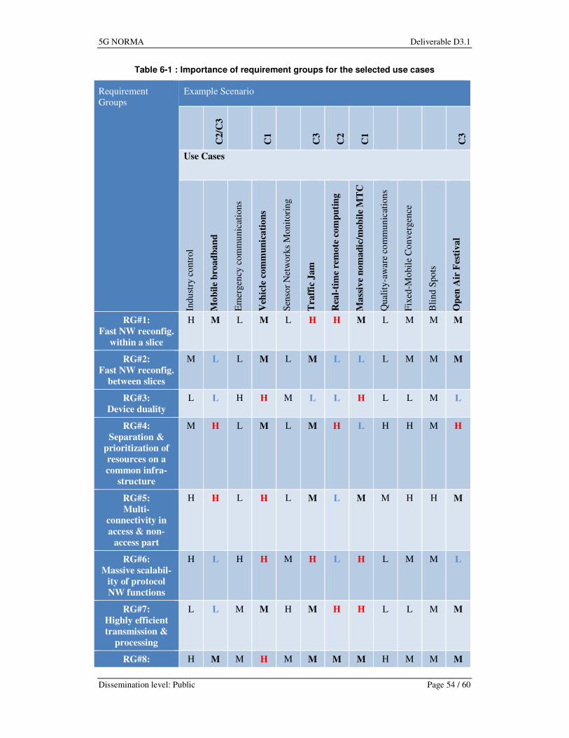
5G NORMA Deliverable D3.1
Dissemination level: Public Page 54 / 60
Table 6-1 : Importance of requirement groups for the selected use cases
Requirement
Groups
Example Scenario
C2/C
3
C1
C3
C2
C1
C3
Use Cases
Indu
stry
contr
ol
Mo
bil
e b
road
ban
d
Em
ergen
cy c
om
munic
atio
ns
Veh
icle
com
mu
nic
ati
on
s
Sen
sor
Net
wo
rks
Monit
ori
ng
Tra
ffic
Jam
Rea
l-ti
me
rem
ote
com
pu
tin
g
Ma
ssiv
e n
om
ad
ic/m
ob
ile
MT
C
Qual
ity-a
war
e co
mm
un
icat
ion
s
Fix
ed-M
obil
e C
onver
gen
ce
Bli
nd S
po
ts
Op
en A
ir F
esti
val
RG#1:
Fast NW reconfig.
within a slice
H M L M L H H M L M M M
RG#2:
Fast NW reconfig.
between slices
M L L M L M L L L M M M
RG#3:
Device duality
L L H H M L L H L L M L
RG#4:
Separation &
prioritization of
resources on a
common infra-
structure
M H L M L M H L H H M H
RG#5:
Multi-
connectivity in
access & non-
access part
H H L H L M L M M H H M
RG#6:
Massive scalabil-
ity of protocol
NW functions
H L H H M H L H L M M L
RG#7:
Highly efficient
transmission &
processing
L L M M H M H H L L M M
RG#8: H M M H M M M M H M M M

5G NORMA Deliverable D3.1
Dissemination level: Public Page 55 / 60
QoE/QoS aware-
ness
RG#9:
Adaptability to
transport NW
capabilities
L H L L L M M L L M H H
RG#10:
Low latency sup-
port
H L L H L L H L L L L L
RG#11:
Security
H M H H M L M H L M L L
Except for the Open Air Festival all selected use cases can be simulated in the proposed Man-
hattan grid deployment of scenario C1. In order to simplify coordination of simulation activities
the Open Air Festival should be excluded from simulation point of view.
The scope of the planned demonstrations can be deduced from Section 6.3.1. The demonstrated
features fit well with the selected use cases and scenarios. As for the mapping of the PoC cam-
paigns to the use cases’ requirements, Table 6-2 presents from a high level point of view the
relationship between the RGs extracted in WP2 and the different demos introduced in Section
6.3.1. As the table shows, most of the RGs are covered by the PoC campaigns, except the ones
related to multi-slice, scalability, high communication/computing efficiency and security. This
is due to the limitations of the PoC available hardware devices, which restrict the amount
(scalability) and performance characteristics (efficiency) of the hardware components used in
the different demos. These PoC shortcomings shall be addressed by the simulator campaigns.
Table 6-2: Requirement groups – demos mapping
Requirement group Software
demo
Hardware
demo
SDMC
demo
RG#1: Fast network reconfiguration
within a network slice Yes Tentative
Yes (the network
slice will reconfigure
itself using SDN
techniques)
RG#2: Fast network reconfiguration
between network slices Tentative No No
RG#3: Device duality
Yes. (only net-
work- controlled
V2X)
No No
RG#4: Separation and prioritization of
resources on a common infrastructure Yes No
Yes (SDN flows re-
routing)
RG#5: Multi-connectivity in access and
non-access part of the 5G system Yes No No
RG #6: Massive scalability of protocol
NFs No No
No (depends on the
size of the testbed)
RG #7: Highly efficient transmission &
processing No No No

5G NORMA Deliverable D3.1
Dissemination level: Public Page 56 / 60
RG #8: QoE/QoS awareness Tentative Yes Yes (QoE / QoS re-
quirement extraction)
RG #9: Adaptability to transport network
capabilities Yes No No
RG #10: Low latency support Yes Yes
Yes (by moving NFs
close to the user and a
better redirection of
data flows)
RG #11: Security No No No
Table 6-3 describes the overview of the scenarios considered for the PoC evaluations. The table
follows the template used in WP2 dividing each scenario in different parts, namely the applica-
tions, deployment & channel model, traffic model, KPIs and relevance of 5G NORMA’s key
innovations.
Table 6-3: Demo scenarios overview
Software
demo
Hardware
demo
SDMC
demo
Application/s
Traffic safety with V2X commu-
nications.
Multimedia file-download.
Video streaming.
Gaming.
Low latency remote
driving (“Real-time
remote computing” in
[18]).
Multimedia, Non-
critical V2X com-
munications.
Deployment
& channel
model
Urban outdoor environment.
Multi-cell heterogeneous network.
Dense small-cell deployment.
Real-world city layout and mobili-
ty mode.
Channel model with support for
frequencies up to 28 GHz and
bandwidths up to 500 MHz.
Urban small cell.
Indoor user being
vehicular up to 5/10
Km/h.
Several BSs, could
be applied to dif-
ferent scenarios.
Traffic mo-
del
V2X communications: time-
critical with low-latency require-
ment.
Video Streaming: delay-tolerant
with high data rate requirements.
Constant bit-rate.
Broadcast for alarms.
Multicast for live streaming of
events.
Low data rate. Video Streaming,
high data rate.
KPIs/ Per-
formance
metrics
User throughput.
E2E latency.
System throughput.
Cell throughput.
E2E Latency.
Reduced latency.
Better infrastruc-
ture utilization.

5G NORMA Deliverable D3.1
Dissemination level: Public Page 57 / 60
Relevance of
5G NOR-
MA’s key
innovations
Adaptive functional composi-
tion/decomposition.
Service-aware and context-aware
adaptation of network functionali-
ty.
Context-aware adap-
tation of NFs.
Adaptive (de) compo-
sition and allocation
of mobile NFs.
Joint optimization of
mobile access/core.
Multi-service and
context-aware ad-
aptation of NFs.
The economic evaluation will also be based on the three example scenarios. In each scenario,
we will assume that massive broadband (MBB) is the baseline service to be deployed and we
will assess the cost and revenue impacts of adding the additional use cases, as defined in the
scenarios.
The objective will be to analyse whether there is a positive net benefit to one or more operators
deploying the infrastructure necessary for each scenario. In other words, whether the incremen-
tal revenues from 5G services in each scenario are likely to be greater than the incremental costs
of the 5G NORMA network over and above the existing costs of legacy networks. We will pro-
ject forward costs and revenues over a suitable timeframe, perhaps 10 years that correspond
broadly to the lifetime of the assets in the 5G network we model. We will calculate the net pre-
sent value of the revenues minus the costs over this time period which is a standard approach to
calculating the financial or economic value of an investment such as this.
In modelling revenues, we are cognizant that there will be a number of ways in which operators
receive revenue services: end-users may pay directly for new services; end-users may pay indi-
rectly by choosing to buy a more expensive subscription for a higher quality service (e.g. lower
latency, guaranteed levels of service) which might be a pre-requisite for applications such as
virtual reality gaming; third parties such as public transport providers may pay directly and end-
users pay indirectly through ticket prices. We also recognise that some proportion of revenues
may go to other service providers than the network operators, such as OTT service providers
and we will seek to take this into account.
In modelling costs we will link demand to the capacity of traffic and demand sensitive network
elements thus ensuring that the revenue calculations are consistent with the cost calculations.
This will ensure that the 5G architecture whose cost we evaluate is fully able to meet the needs
of the scenario i.e. the underlying demand from all the services that need to be delivered within
each scenario and given the technical KPIs which have been set out in the use case descriptions
in [18].
We will also introduce geographic specificity into our modelling so that we can take into ac-
count the different network deployment needs of urban, suburban, and rural areas. We intend to
model sample geographic areas which contain the necessary mix of geographic areas that are
relevant to each scenario. If appropriate for the economic evaluation, we may scale up results
from sub-national sample areas to a national level.
7 Summary and Conclusions
This report provided a comprehensive and concise overview of the 5G NORMA architecture. It
detailed the underlying requirements which result in qualitative as well as quantitative metrics.
Qualitative metrics include flexibility and scalability which are difficult to measure but highly
important in a 5G system where a multitude of functionalities needs to cope with diverging re-
quirements. We further defined quantitative metrics which are relevant for the 5G NORMA
architecture and which must be evaluated rather for scenarios composed of multiple use cases
than for single use cases alone. Finally, the two main functional requirements were detailed, i.e.

5G NORMA Deliverable D3.1
Dissemination level: Public Page 58 / 60
mobile network multi-tenancy and multi-service and context-aware adaptation and allocation of
NFs.
Furthermore, the key innovative enablers are introduced, namely software-defined mobile net-
work control and orchestration, adaptive composition and allocation of NFs, and joint optimiza-
tion of mobile access and core. These key enablers may not be fully supported with existing
architectures but are important in order to accommodate the diverse service landscape in a 5G
mobile network. Furthermore, these key enablers are necessary to fulfill the operational re-
quirements derived in this report.
Due to the complexity of the architecture, the report introduced four distinct architecture views
along the two major functional requirements and two major key technologies. These different
views are required in order to analyse and evaluate the architecture which is not possible with a
single view on the architecture. Most important, these different architecture views are used to
further develop novel technologies for the 5G NORMA mobile network architecture.
Finally, we introduced the 5G NORMA validation concept which must evaluate both qualitative
and quantitative metrics. This is done through a well defined validation process which incorpo-
rates the architecture definition in this document as well as PoC demonstrators, simulation cam-
paigns, and analytical tools. While PoC demonstrator allow for concluding whether a specific
technology is feasible, simulation campaigns allow for concluding whether these technologies
provide the promised benefits also in a system. In addition, analytical tools allow for evaluating
scalability as well as consistency of protocols.
In the next report, the 5G NORMA architecture will be further detailed, also including specific
technologies developed in WPs 4 and 5.
8 References
[1] A. Banchs, M. Breitbach, X. Costa, U. Doetsch, S. Redana, C. Sartori, and H. Schotten:
“A Novel Radio Multiservice Adaptive Network Architecture for 5G Networks,” IEEE
VTC Spring 2015, Glasgow, Scotland, May 2015
[2] NGMN Alliance: “5G White Paper”. Version 1.0, 17 Feb. 2015,
https://www.ngmn.org/uploads/media/NGMN_5G_White_Paper_V1_0.pdf
[3] D. Wübben, P. Rost, J. Bartelt, M. Lalam, V. Savin, M. Gorgoglione and A. Dekorsy,
“Benefits and Impact of Cloud Computing on 5G Signal Processing“, IEEE Signal Pro-
cessing Magazine, vol.31, no.6, pp.35-44, Nov. 2014
[4] EU FP7 iJOIN, “D5.2: Final definition of iJOIN requirements and scenarios,” Available:
http://www.ict-ijoin.eu/deliverables
[5] EU FP7 iJOIN, “D5.3: Final definition of iJOIN architecture,” online, Available:
http://www.ict-ijoin.eu/deliverables
[6] P. Rost, C. J. Bernardos, A. De Domenico, M. Di Girolamo, M. Lalam, A. Maeder, D.
Sabella, D. Wübben, “Cloud Technologies for Flexible 5G Radio Access Networks“, IEEE
Communications Magazine, vol.52, no.5, pp.68-76, May 2014
[7] C. Bernardos, A. De Domenico, J. Ortin, P. Rost, and D. Wübben, “Challenges of design-
ing jointly the backhaul and radio access network in a cloud-based mobile network,” Fu-
ture Network and Mobile Summit (FutureNetworkSummit), Lisbon, Portugal, July 2013
[8] F. Giust, L. Cominardi, C. Bernardos, “Distributed mobility management for future 5G
networks: overview and analysis of existing approaches“, IEEE Communications Magazine,
vol.53, no.1, pp.142,149, January 2015

5G NORMA Deliverable D3.1
Dissemination level: Public Page 59 / 60
[9] C.J. Bernardos, A. de la Oliva, P. Serrano, A. Banchs, L.M. Contreras, H. Jin and J.C.
Zúñiga, “An Architecture for Software Defined Wireless Networking“, IEEE Wireless
Communications, vol.21, no.3, pp.52,61, June 2014
[10] ICT-317669 METIS, Deliverable D6.3 “Intermediate system evaluation results,” August
2014, Available: https://www.metis2020.com/documents/deliverables/.
[11] J. Eichinger, et al., “Building a New Multi-Facial Architecture of 5G”, IEEE MMTC E-
Letter, September 2014.
[12] P. Agyapong, M. Iwamura, D. Staehle, W. Kiess, and A. Benjebbour, “Design Considera-
tions for a 5G Network Architecture,” IEEE Communications Magazine, vol. 52, no. 11,
November 2014.
[13] ETSI Industry Network Functions Virtualisation Industry Specification Group (NFV
ISG), White Papers, Specifications, etc., http://www.etsi.org/technologies-
clusters/technologies/nfv.
[14] 4G Americas, “Bringing Network Function Virtualization to LTE”, White Paper, No-
vember 2014.
[15] 3GPP TR 22.852, Study on Radio Access Network (RAN) Sharing enhancements,
Rel.13, Sep. 2014.
[16] 3GPP TS 32.130, Telecommunication management; Network Sharing; Concepts and
requirements, Rel.12, Dec. 2014.
[17] 3GPP TS 23.251, Network Sharing; Architecture and Functional Description, Rel.12, Jun
2014.
[18] EU H2020 5G NORMA, “D2.1: Use cases, scenarios, and requirements,” September
2015
[19] 3GPP TS 33.401, 3GPP System Architecture Evolution (SAE); Security architecture,
Release 13, September 2015
[20] 3GPP TR 33.821, Rationale and track of security decisions in Long Term Evolution
(LTE) RAN / 3GPP System Architecture Evolution (SAE), Release 9, June 2009
[21] L. Cominardi, C.J. Bernardos, P. Serrano, A. Banchs, and A. de la Oliva, “An SDN-based
architecture for 5G networks: design and proof of concept,” submitted to IEEE Network
Magazine, November 2015
[22] ETSI GS NFV-MAN 001, “Network Functions Virtualisation (NFV); Management and
Orchestration”, V1.1.1 (2014-12), December 2014
[23] 3GPP 36.300, Evolved Universal Terrestrial Radio Access (E-UTRA) and Evolved Uni-
versal Terrestrial Radio Access Network (E-UTRAN); Overall description; Stage 2, Re-
lease 13, September 2015
[24] Peter Ashwood Smith: “CPRI ‘FrontHaul’ requirements discussion with TSN”. July
2014, San Diego, CA; http://www.ieee802.org/1/files/public/docs2014/new-ashwood-tsn-
cpri-fronthaul-0714-v03.pdf
[25] Harrison J. Son, S. M. Shin: “Fronthaul Size: Calculation of maximum distance between
RRH (at cell site) and BBU (at CO)”. Netmanias Tech-Blog, April 1st, 2014,
http://de.slideshare.net/Netmanias/netmanias20140401calculation-of-fronthaul-fiber-
distance-en
[26] Kevin Murphy: “Centralized RAN and Fronthaul”. Whitepaper, Ericsson Inc. OSP Maga-
zine, May 2015, http://www.ospmag.com/files/pdf/whitepaper/C-
RAN_and_Fronthaul_White_Paper.pdf

5G NORMA Deliverable D3.1
Dissemination level: Public Page 60 / 60
[27] ITU-T, SERIES Z: LANGUAGES AND GENERAL SOFTWARE ASPECTS FOR
TELECOMMUNICATION SYSTEMS, Formal description techniques (FDT) – Message
Sequence Chart (MSC), Recommendation ITU-T Z.120 (02/2011), February 2011
[28] D. Bertsekas, R. Gallagher: Data Networks. Prentice Hall, Englewood Cliffs, 1992
[29] ICT-317669 METIS, Deliverable D6.4, “Final report on architecture,” January 2015,
Available: https://www.metis2020.com/documents/deliverables/.
[30] Open Networking Foundation, “Software-Defined Networking: The New Norm for Net-
works”, [online document], White Paper, April 2012.
[31] Open Networking Foundation, “OpenFlow-Enabled Mobile and Wireless Networks,”
Technical report, September 2013
[32] US National Institute of Standards and Technology (NIST), “The NIST Definition of
Cloud Computing”, 2011, available at http://csrc.nist.gov/publications/nistpubs/800-
145/SP800-145.pdf
[33] ETSI GS NFV 002, V1.1.1, “Network Functions Virtualisation (NFV); Architectural
Framework”, 2011
[34] ETSI GS NFV 003, V1.2.1, “Network Functions Virtualisation (NFV); Terminology for
Main Concepts in NFV”, 2014
[35] 3GPP TR 36.874, Coordinated multi-point operation for LTE with non-ideal backhaul,
Release 12, December 2013
[36] 3GPP TR 36.819, Coordinated multi-point operation for LTE physical layer aspects, Re-
lease 11, September 2013