deliverable d19 - wp0 t0+24 final project report - v2.1 · exploring the limits of fractal ......
TRANSCRIPT

- 1 -
FRACTALCOMS
IST-2001-33055
Exploring the limits of Fractal Electrodynamics for the future telecommunication technologies
Final Project Report Covering period from 1-12-2001 to 30-11-2003
Report Version: 2.1
Report Preparation Date: January 02, 2004
Classification: Public
Contract Start Date: December 1, 2001 Duration: 2 years
Project Co-ordinator: Universitat Politècnica de Catalunya (UPC)
Partners:
Universitat Politècnica de Catalunya (UPC)
“La Sapienza” Università degli studi di Roma (ROME)
École Polytechnique Fédérale de Lausanne (EPFL)
Universidad de Granada (UGR)
Centro Internacional de Métodos Numéricos en Ingeniería (CIMNE)
Project funded by the European Community under the “Information Society Technologies” Programme (1998-2002)

- 2 -
FRACTALCOMS Exploring the limits of Fractal Electrodynamics for the future telecommunication technologies
IST-2001-33055
T0+24 Final report
Deliverable reference: D19
Contractual Date of Delivery to the EC: January 31, 2004
Author(s): Juan M. Rius
Participant(s): UPC
Workpackage: WP0
Security: Public
Nature: Report
Version: 2.1 Date: 05 January 2004
Total number of pages: 149
Keyword list: FRACTALCOMS, final report
Abstract:
T0+24 final report of FRACTALCOMS project.

- 3 -
TABLE OF CONTENTS
1 Executive summary and project conclusions.................................................................... 6
2 Management issues ......................................................................................................... 10
2.1 Schedule .............................................................................................................. 10
2.2 Funding................................................................................................................ 11
2.3 Deliverables ......................................................................................................... 11
2.4 Consortium agreement......................................................................................... 11
3 Project meetings summary.............................................................................................. 12
3.1 Kick-off meeting ................................................................................................. 12
3.2 T0+6 meeting....................................................................................................... 12
3.3 T0+12 meeting..................................................................................................... 13
3.4 T0+18 meeting..................................................................................................... 13
3.5 T0+24 meeting..................................................................................................... 14
4 Workshops, seminars and partners meetings.................................................................. 14
4.1 1st UPC-CIMNE workshop................................................................................. 14
4.2 Seminar at ROME ............................................................................................... 15
4.3 2nd UPC-CIMNE workshop ............................................................................... 15
4.4 3rd UPC-CIMNE workshop ................................................................................. 15
4.5 4th UPC-CIMNE workshop ................................................................................. 16
4.6 5th UPC-CIMNE workshop ................................................................................. 16
5 Dissemination activities.................................................................................................. 17
5.1 International conferences..................................................................................... 17
5.2 International Journals .......................................................................................... 20
5.3 FRACTALCOMS project web site ..................................................................... 22
6 World-wide state-of-the-art update................................................................................. 23
6.1 Small antennas..................................................................................................... 23
6.2 Performance of pre-fractal antennas.................................................................... 23
6.3 Review papers ..................................................................................................... 24
7 Clarifications on 1st YEAR review comments and recommendations ........................... 25
WP1: Theory of fractal electrodynamics............................................................................. 26
T1.1: Understanding fractal electrodynamics phenomena .............................................. 26
On the Influence of Fractal Dimension and Topology on Radiation Efficiency and Quality Factor of Self-Resonant Pre-fractal Wire Monopoles .................................... 26
Study of 3D pre-fractals .............................................................................................. 29
On the resonant frequency of pre-fractal miniature antennas...................................... 30
Benchmarks for pre-fractal antenna performance ....................................................... 32

- 4 -
Task conclusions and design guidelines...................................................................... 34
Task 1.2: Fundamental limits of fractal miniature devices ............................................. 36
WP2: Vector calculus on fractal domains ........................................................................... 41
Task 2.1: Solution of EM simple problems on fractal domains ...................................... 41
Task 2.2: Formulation of EFIE on fractal domains ......................................................... 42
WP3: Software simulation tool ........................................................................................... 44
Task 3.1: Advanced meshing of fractal structures .......................................................... 44
Nystrom method high-order discretization scheme..................................................... 44
Modeling pre-fractal antennas ..................................................................................... 45
Meshing pre-fractal antennas....................................................................................... 46
New basis functions..................................................................................................... 49
Treatment of T-junctions ............................................................................................. 50
Task 3.2: Formulation of numerical methods for fractal structures ................................ 51
Validity of the thin-wire approximation:..................................................................... 51
Implementation of wire antenna analysis in FIESTA computer code:........................ 52
New approaches for solving the EFIE of wire antenna analysis: ................................ 53
Task 3.3: Simulation of fractal structures in the frequency domain................................ 54
Optimisation of iterative solver multilevel algorithms................................................ 55
Efficient evaluation of the full-kernel of thin-wire EFIE............................................ 56
Task 3.4: Simulation of fractal structures in the time domain......................................... 57
WP4: Fractal devices development ..................................................................................... 60
Task 4.1: Design of fractal-shaped miniature devices..................................................... 60
Superconductive resonators and filters........................................................................ 60
Pre-fractal loading ....................................................................................................... 63
Pre-Fractal Quasi self-complementary antennas ......................................................... 65
The Y-Wired Sierpinski Monopole ............................................................................. 68
3-D Pre-fractal tree ..................................................................................................... 69
Design of small antennas using Genetic Algorithms (GA) ......................................... 69
The H pre-fractal tree .................................................................................................. 70
Pre-fractal capillary devices ........................................................................................ 72
Task 4.2: Technological limitations of fractal-shaped devices ....................................... 74
Task 4.3: Prototype construction and measurement........................................................ 77
Measurement of radiation efficiency and quality factor of fractal antennas: the Wheeler cap method .................................................................................................... 77
Genetically designed planar monopoles ...................................................................... 78
The 3D Hilbert monopole: an example of 3D pre-fractal small antenna .................... 79
Prototypes and measurements at EPFL ....................................................................... 80

- 5 -
Task conclusions ......................................................................................................... 83
Appendix 2- Deliverables table (1st year)............................................................................ 84
Appendix 2- Deliverables table (2nd year)........................................................................... 85
Appendix 3- Summaries of deliverables ............................................................................ 86
Appendix 4 (a)- Comparative Information on Resources (Person months) – 1st YEAR .. 105
Appendix 4 (a)- Comparative Information on Resources (Person months) – 2nd YEAR . 106
Appendix 4 (b) - Comparative Information on Resources (Costs) – 1st Year ................... 107
Appendix 4 (b) - Comparative Information on Resources (Costs) – 2nd Year .................. 108
Appendix 5 – Progress Overview Sheet (UPC) ................................................................ 109
Appendix 5 – Progress Overview Sheet (ROME)............................................................. 116
Appendix 5 – Progress Overview Sheet (EPFL)............................................................... 121
Appendix 5 – Progress Overview Sheet (UGR)................................................................ 126
Appendix 5 – Progress Overview Sheet (UGR)................................................................ 128
Appendix 5 – Progress Overview Sheet (CIMNE) ........................................................... 131
8 Appendix 6 – Project's Achievements Fiche ................................................................ 135
9 Appendix 8 – Intention to protect intellectual property................................................ 148
Disclaimer.......................................................................................................................... 149

- 6 -
1 EXECUTIVE SUMMARY AND PROJECT CONCLUSIONS
Project objectives The project objectives, as stated in the Appendix I of the contract, are:
1- Increase the know-how in Fractal Electrodynamics theory and understand better the behavior of electromagnetic fields and electric currents in fractal domains, in order to acquire guidelines for the design of fractal-shaped antennas and microwave devices.
2- Explore if fractal-shaped microwave devices can reach the fundamental miniaturization limit, which has been never reached by Euclidean-shaped devices.
3- Develop a software tool for computer simulation of fractal-shaped microwave devices performance, including time domain visualization of the interaction between geometry and electromagnetic fields, in order to allow a physical interpretation of radiation and resonance of the proposed structures. This tool would allow also the later design and optimization of such devices.
4- Explore the impact of the technological limitations on the performance of fractal-shaped microwave devices, including minimum detail size and loss efficiency.
5- It must be remarked that this is a FET project and therefore the main objective is an increase of knowledge. Fractal antennas are becoming increasingly popular and many European SMEs, driven by the need of offering up-to-date state-of-the-art products, may decide to tackle risks by including them in their production lines. This project should provide answers about the potential interest of fractal antennas, through a careful study of electrical performance vs. technological complexity trade-offs.
The project has achieved all the five goals set up in the proposal, and additionally has paved the way to new technological applications.
The goals of the project were twofold. In one hand to develop the theoretical, and software tools to better understand fractal electrodynamics, and in particular the radiation and scattering of fractal structures, and on the other hand to design, build, and assess the properties of prototypes in order to validate theory and evaluate technological limitations.
In particular, the project has found what are the fundamental and technological limitations of miniature pre-fractal antennas and microwave devices, and how do they perform compared with the conventional ones. Small antennas design guidelines have been derived. Among the many miniature antennas and devices that have been designed, analyzed and/or measured, the ones that have an outstanding performance are the two-arm square spiral antenna and the Hilbert superconductor resonators for miniature filters. The project results are an important contribution to European SMEs interested in designing and manufacturing miniature antennas and microwave devices.

- 7 -
Main contributions: The definition of pre-fractal geometries through an IFS allows to create extremely complex structures. Nevertheless, their intrinsic regularity simplifies their definition, modeling and somehow its numerical analysis.
• From the theoretical point of view it has been shown the well-posedeness of fractal electrodynamics and the convergence of classical EM numerical approaches applied to fractal domains. The main contributions in this field are:
- Rigorous formulation of field problems on fractal structures (and specifically fractal curves).
- Fully based on IFS through the concept of augmented IFS.
- First rigorous theoretical formulation of EFIE on fractal wire antennas.
- Numerical approaches based on Galerkin truncation of EFIE on wire antennas parametrized with respect to the normalized curvilinear abscissa.
• The study of the interaction of pre-fractal geometries with EM fields provides knowledge on properties of extremely complex structures otherwise difficult to attain.
• The conclusions derived from the behavior of small wire pre-fractal antennas lead to useful design criteria for better small wire antennas.
• The numerical analysis tools developed for the study of small wire pre-fractal antennas can be used with advantage in the analysis of complex high-detailed small near-resonance structures, such as PBG, metamaterials, etc. The time domain code developed during this project has been an invaluable tool for understanding the physical processes related to the behaviour of pre-fractal antennas. Specifically it has been very useful for understanding the role played by the “short cuts”.
• An intuitively user-prone approach to complex pre-fractal definition and automatic meshing has been developed and fully tested. This tool allows for the generation of thin wire as well as planar geometries. CIMNE will exploit all the utilities for the mesh generation of Fractal geometries by incorporating them in the commercial version of GiD. In this way, the construction of meshes for Fractal geometries is a new utility of the pre-process capabilities of GiD and, therefore, it has been made available to the scientific and engineering community, not restricted to the EM community. A free license of GiD will be provided by CIMNE to the rest of partners of the FRACTALCOMS project for, at least, two additional years after the end of the project.
• The knowledge gained in understanding the behavior of small pre-fractal wire antennas can be applied in using pre-fractal geometries to other EM devices.
Understanding fractal electrodynamics phenomena: From the specific point of view of antenna miniaturization keeping reasonable bandwidth and efficiency, the following conclusions have been reached, based on the results of both numerical simulations and prototype measurements:
• Increasing the number of pre-fractal iterations means a reduction on resonant frequency, radiation efficiency and an increase on quality factor. The increase of fractal dimension, although making better space filling curves, builds larger monopoles with lower efficiencies and higher quality factors even for the first iterations.

- 8 -
• Topology has a stronger influence than fractal dimension on the behaviour of small 2D pre-fractal wire monopoles, in particular on the losses efficiency.
• As the number of loops inside the structure increases, efficiency and fractional bandwidth (inverse of quality factor) seem to increase with the order of the pre-fractal (number of IFS iterations).
• When there is no loop, each IFS iteration increases the length and bending of the wires, and as a consequence ohmic losses and the amount of stored energy on the surrounding of the antenna increases (this means lower radiation efficiencies and higher quality factors).
• When the number of IFS iterations increases beyond a certain threshold, the change in radiation patterns and input impedance of the antenna tend to zero. In other words, there is no use in increasing the number of IFS iterations. Convergence is usually achieved between 4 and 6 iterations. This value depends largely on the size, wire or strip width and topology of the antenna.
• The hypothesis of electromagnetic coupling –or shortcuts- between corners fully explains why the resonant frequency of pre-fractal antennas is much larger than what could be expected from the wire length only and why it stagnates as the number of IFS iterations increases.
• It seems that the high-gain localized modes than have been previously observed in the Koch-island printed patch antenna are not exclusive of pre-fractal antennas.
• Three-dimensional pre-fractal design does not provide further improvements than planar design in the radiation performance of monopoles. In spite of the smaller electrical sizes attainable thanks to their increased space-filling capability, they have a more intricate topology and larger wires than their planar counterparts. Consequently, efficiency and Q factor for these 3D pre-fractals have unpractical values to real-world applications.
Guidelines for the design of small antennas: As a result of the work in this project (the electromagnetic coupling hypothesis) and very recent work available in the literature, some guidelines for the design of small antennas have been derived:
1- In order to reduce signal coupling –or shortcuts- between wire segment angles, the distance between those angles must be as large as possible, and the angles the larger possible.
2- In order to reduce the signal coupling between the feeder and the wire segments, the most possible wire length must be perpendicular to the electric field radiated by the feeder.
3- In order to reduce coupling between wire segments, parallel wire segments with opposite (anti-parallel) currents very close to each other must be avoided.
An example of wire antenna that closely follows these guidelines is a two-arm square spiral. The resonant frequency of a square spiral is inversely proportional to the wire length, while keeping the wire enclosed by a small square.

- 9 -
Fundamental limits: The fundamental bandwidth limitation has been studied. It has been empirically assessed that the fundamental Chu-McLean limit of radiation quality factor of antennas holds even for pre-fractal devices. Moreover, pre-fractals are not closer to this borderline than other standard conventional designs.
• A multi-objective optimisation technique based on Genetic Algorithms (GA) assessed the existence of practical limits more restrictive than the fundamental limit predicted by Chu and reviewed by McLean. Both conventional and pre-fractal geometries are near this practical limit. The limit has been found for planar self-resonant wire monopoles.
• A more realistic limit that holds for antennas with sinusoidal current distribution has been recently published. The practical bandwidth limit found in this task agrees very well with the new theoretical limit recently found by Thiele et al. in 2003.
Technological limitations: From the point of view of technological limitations two issues must be considered. First the limitations related to the modeling and numerical analysis of highly iterated pre-fractals, and second the limitation related to their manufacturing. Concerning these two issues the following conclusions have been reached:
• The best way to accurately model highly iterated pre-fractal curves is a extrusion-strip model rather than a planar strip or a thin wire. For that reason, most of the simulations in WP3 aimed at drawing conclusions for WP1 have been made with extrusion-strip models.
• Thin-wire models with reduced kernel are still useful for analysing low-order pre-fractals, and therefore NEC and the time-domain DOTIG code have been extensively used in this project.
• In order to analyze highly iterated pre-fractals with the thin-wire EFIE, a new formulation has been developed to achieve a very fast evaluation of the full kernel. The new formulation is valid for any ratio of the wire segment length to the wire radius, and can be applied to highly iterated pre-fractals discretized in very short wire segments. The main advantage of the new thin-wire full kernel approach over the 2-D extrusion-strip formulation is that computation time is very small, since the 1-D discretization requires, for instance, only 4096 unknowns while the 2-D mesh has 22,524 unknowns to model a 5-iteration Koch antenna.
• Technological manufacturing limitations make impossible the construction of highly iterated pre-fractals for reduced overall dimensions, due to the non-zero width of the pre-fractal curve. Nevertheless it has been shown, both theoretically and practically, that convergence is reached after a reduced number of iterations.
Design of pre-fractal devices: Besides the objectives set on the proposal new approaches have been explored related to the following technological application of pre-fractals:
- Superconductor pre-fractal resonators for miniature filters.
- Quasi-self complementary pre-fractal antennas.
- GA optimized highly convoluted miniature antennas.
- H-trees and Capillary filters.

- 10 -
2 MANAGEMENT ISSUES
There have been no substantial changes along the project life. The most significant are:
2.1 Schedule
1- It was decided in the kick-off meeting that tasks
o T3.3: Simulation of fractal structures in the frequency domain
o T3.4: Simulation of fractal structures in the time domain
would start at T0 although they were originally scheduled to start at T0+9.
2- It was decided at the T0+6 meeting that task T4.3: Prototype construction and measurement would start at T0+6 although it was originally scheduled to start at T0+9.
3- Some partners (UGR and ROME) have participated in more tasks and workpackages than initially scheduled.
o UGR: Has participated also in WP1 and WP4.
o ROME: Has participated also in WP3.
Task 1.1: Understanding fractal electrodynamics phenomena
Task 2.1: Solution of electromagnetic simple problems
Task 3.1: Advanced meshing of fractal structures
Task 3.4: Simulation of fractal structures in the time domain
Task 4.2: Technological limitations of fractal devices
Task \ Month
Task 1.2: Fundamental limits of fractal miniature devices
Task 2.2: Formulation of EFIE on fractal domains
Task 3.2: Formulation of numerical methods
Task 3.3: Simulation of fractal structures, frequency domain
Task 4.1: Design of fractal-shaped miniature devices
Task 4.3: Prototype construction and measurement
3 6 9 12 15 18 21 24
Task 1.1: Understanding fractal electrodynamics phenomenaTask 1.1: Understanding fractal electrodynamics phenomena
Task 2.1: Solution of electromagnetic simple problemsTask 2.1: Solution of electromagnetic simple problems
Task 3.1: Advanced meshing of fractal structuresTask 3.1: Advanced meshing of fractal structures
Task 3.4: Simulation of fractal structures in the time domainTask 3.4: Simulation of fractal structures in the time domain
Task 4.2: Technological limitations of fractal devicesTask 4.2: Technological limitations of fractal devices
Task \ MonthTask \ Month
Task 1.2: Fundamental limits of fractal miniature devicesTask 1.2: Fundamental limits of fractal miniature devices
Task 2.2: Formulation of EFIE on fractal domainsTask 2.2: Formulation of EFIE on fractal domains
Task 3.2: Formulation of numerical methodsTask 3.2: Formulation of numerical methods
Task 3.3: Simulation of fractal structures, frequency domainTask 3.3: Simulation of fractal structures, frequency domain
Task 4.1: Design of fractal-shaped miniature devicesTask 4.1: Design of fractal-shaped miniature devices
Task 4.3: Prototype construction and measurementTask 4.3: Prototype construction and measurement
3 6 9 12 15 18 21 24
Workpackage \ Partner UPC ROME EPFL UGR CIMNE
WP0. Project Management
WP1. Theory of fractal electrodynamics
WP2. Vector calculus on fractal domains
WP3. Software simulation tool
WP4. Fractal devices development
Workpackage \ Partner UPC ROME EPFL UGR CIMNE
WP0. Project Management
WP1. Theory of fractal electrodynamics
WP2. Vector calculus on fractal domains
WP3. Software simulation tool
WP4. Fractal devices development

- 11 -
2.2 Funding
Advanced and first year payments have been transferred to partners.
There have been no budget rebalances.
Before the end of the project, UGR and UPC partners requested a small budget rebalance between costs category, but it was not deemed necessary by the project officer. The budget rebalance will be done, if necessary, after the cost claims have been submitted to the EC.
2.3 Deliverables
The following deliverables have been generated and submitted to the project officer before the contractual deadlines:
D1: Final task report 1.1 (Understanding Fractal Electrodynamics Phenomena)
D2: Final task report 1.2 (Fundamental Limits of Fractal Miniature Devices)
D3: Final task report T2.1 (Solution of Electromagnetic simple problems)
D4: Final task report T2.2 (Formulation of EFIE on Fractal Domains)
D5: Final task report 3.1 (Advanced Meshing of Fractal Structures)
D6: Final task report 3.2 (Formulation of numerical methods for fractal structures)
D7: Final task report 3.3 (Simulation of fractal structures: frequency domain)
D8: Final task report 3.4 (Simulation of fractal structures: time domain)
D9: Final task report 4.1 (Design of fractal shaped miniature devices)
D10: Final task report 4.2 (Technological limitations of fractal devices)
D11: Final task report 4.3 (Prototype construction and measurement)
D13: Project presentation
D14: Dissemination and Use Plan
D15: Project web site (http://www.tsc.upc.es/fractalcoms)
D16: T0+6 intermediate report Contains partners T0+6 progress reports as annexes.
D17: T0+12 annual report Contains partners T0+12 progress reports as annexes.
D18: T0+18 intermediate report Contains partners T0+18 progress reports as annexes.
D19: T0+24 final report (this document).
The following deliverable:
D12: Built prototypes
will be delivered to the project officer at the final review meeting on January 23rd.
2.4 Consortium agreement
At the T0+18 meeting, all partners approved the Consortium Agreement. The Agreement has already been signed by the legal representatives of all partners.

- 12 -
3 PROJECT MEETINGS SUMMARY
3.1 Kick-off meeting
The kick-off meeting was held on December 13-14 2002 at UPC, Barcelona. All partners were represented.
Several project management issues were agreed, the most important of which are:
Since all FRACTALCOMS deliverables are public domain, partners are allowed to submit papers for publication before the corresponding project deliverable is sent to the Commission.
A copy of all papers related to the project and submitted for publication will be send to the coordinator, who will post them in the project website information hub, when available, or distribute among all partners if the web site is not available.
The most important technical issues agreed were:
Restrict the research to Fractal geometries than can be generated by an Iterated Function System (IFS), with emphasis on wire antennas.
In task 2.2 (Formulation of Electric Field Integral Equation (EFIE) on fractal domains), the analysis will be restricted to wire antennas.
CIMNE will provide a license of GiD pre- and post-processing software to all partners.
The following tasks, originally scheduled to start at T0+6 or later, will effectively start at T0+6:
o Task 3.3: “Simulation of fractal structures in the frequency domain”.
o Task 3.4: “Simulation of fractal structures in the time domain”.
3.2 T0+6 meeting
The T0+6 meeting was held at EPFL, Lausanne, on June 10-11, 2002. All partners were represented.
The most important management issues agreed were:
Consortium agreement: The importance of the consortium agreement was stressed. The coordinator will prepare a draft to be discussed at T0+12 meeting.
Project web site: All approved reports, documents and deliverables generated by the project will be public at the FRACTALCOMS web site. Access will be restricted only to consortium partners before the documents are approved by the project coordinator. Manuscripts submitted to journals and conferences that have been accepted for publication will be also public. Before they are accepted, access will be restricted to consortiums partners only.
The most important technical issue agreed was:
It was decided that task T4.3: “Prototype construction and measurement” would start at T0+6 although it was originally scheduled to start at T0+9.

- 13 -
3.3 T0+12 meeting
The T0+12 meeting was held at UGR, Granada, on November 28-29, 2002. All partners were represented.
The T0+6 meeting was held at EPFL, Lausanne, on June 10-11 2002. All partners were represented.
The most important management issues agreed were:
Cost statements: The UPC “Center for Technology Transfer (CTT)” will help the partners who do not have a similar office (ROME) to prepare the cost statement.
Consortium agreement: The consortium agreement draft was delivered to all partners by the coordinator. Partners are urged to send the coordinator any amendments as soon as possible.
Project evaluation: It was agreed that the number of participants would be restricted to a strict minimum, but having all expertise present to answer to any of the scientific questions the reviewers might have. The consortium representatives will be: Juan M. Rius (UPC, coordinator), Juan R. Mosig (EPFL), Max Giona (ROME) and Gabriel Bugeda (CIMNE). Juan M. Rius will cover the work of UGR partner. It was later agreed in January that J. Romeu, from UPC, would also attend the evaluation meeting.
T0+18 meeting: Will be held at ROME on may 22-23.
CIMNE partner: Will continue working in the project after T0+12, although their participation was scheduled in the contract as 20 man-months in the first year and 0 in the second.
The most important technical issues agreed were:
It was agreed to define a set of design problems, in which some parameters of the antenna have to be optimized while having restrictions in the other parameters; and a set of benchmark problems to assess if different numerical methods from different groups give the same results.
All partners agree that the fundamental limit of the quality factor for a linearly polarized small antenna is much lower than what can be achieved in practice with wire antennas. Other authors have reached the same conclusion. The fundamental limit is only a lower bound in the quality factor, but not a limit to which future and better generations of miniature antennas can converge.
3.4 T0+18 meeting
The T0+18 progress meeting was held at Rome, on May 22 and 23, 2003. All partners were represented.
The most important management issues agreed were:
Consortium agreement: The consortium agreement draft was approved by all partners.
Project evaluation: The annual project review results were presented by the coordinator. The actions to implement the reviewers suggestions were discussed.
T0+24 final project meeting: Will be held at CIMNE (Barcelona) on November 7-8.

- 14 -
3.5 T0+24 meeting
The T0+24 meeting was held at CIMNE (Barcelone), on November 6 and 7, 2003. . All partners were represented.
The main project results were presented and discussed.
The contents of the TIP deliverable was also discussed.
It was agreed that the same consortium will present a new IST-FET project proposal in order to continue the research initiated in this project.
4 WORKSHOPS, SEMINARS AND PARTNERS MEETINGS
4.1 1st UPC-CIMNE workshop
Date: February 27, 2002
A workshop with UPC and CIMNE partners was held at UPC in February 27, 2002 (see annex to deliverable D16).
The objectives of the workshop were:
• Let CIMNE know the adaptive meshing needs for Fractal Antennas.
• Present the most basic concepts of Iterated Function Systems (IFS) to CIMNE.
• See what is possible to implement in GiD within the framework of the project. GiD is an advanced modelling and meshing software tool developed by CIMNE, that is available to all partners in FractalComs project.
• Establish the geometry parameters input for the new code to be developed in GiD.
• Define actions to do in task 3.1 b).
It was agreed that:
• UPC will mesh extrusion-strip antennas (Fig. 1).
• CIMNE will implement a plug-in in GiD in order to mesh planar-strip (Fig. 2) and planar-surface antennas according to UPC specifications. The mesh must be adaptive and element numbering such that the resulting linear system matrix has multilevel block structure. In the case of planar-surface antennas, the mesh will include the electric connections between surface patches that share only one vertex.
• Cylindrical-wire fractal antennas are very difficult to model because a lot of surface-surface intersections must be computed. This kind of model is not essential for numerical simulations, since most fractal antennas are printed strips and cylindrical wires can be modelled by one-dimensional wires and a radius parameter if some approximations are made in the electromagnetic computation code. For that reason it was decided that meshing cylindrical wires would be the least priority task for CIMNE, and very possibly out of the framework of this project.
-101 x 10 -3
0
0.01
0 0.01 0.02 0.03 0.04 0.05 0.06
-101 x 10 -3
0
0.01
0 0.01 0.02 0.03 0.04 0.05 0.06
Fig. 1.One iteration extrusion-strip Koch antenna, discretized in triangular patches.
Fig. 2. One iteration planar-strip Koch antenna, discretized in triangular patches.

- 15 -
4.2 Seminar at ROME
A seminar on “Fractal modelling with Iterated Function Systems” was held at Rome on February 13-15. The ROME group gave the other partners an in-depth introduction to fractal algebra. The seminar was important in setting-up a common terminological background for all partners and in pinpointing key mathematical issues. The documentation of the seminar was attached as an Annex to T0+6 report (D16).
4.3 2nd UPC-CIMNE workshop
Date: July 19
A second workshop with UPC and CIMNE partners was held at UPC on July 19 (see annex).
The objectives of the workshop were:
Discuss if a universal tool for meshing any pre-fractal defined by an IFS will be developed by CIMNE or, on the contrary, CIMNE will create many meshing utilities for different IFS geometries.
Establish the mesh definition output for the new code to be developed in GiD.
It was agreed that:
CIMNE will develop a universal tool for meshing any pre-fractal defined by an IFS. In the first place only the simplest case will be considered: Pre-fractal curves with no intersections, no common nodes and no bifurcations.
UPC would send CIMNE printed information about pre-fractals and IFS, containing the definition of the initiator and the generator.
UPC would send CIMNE an algorithm to convert a pre-fractal curve into a strip, including the more complicated cases with intersections and bifurcations.
Developing a mesh numbering scheme that produces a linear system with recursive block structure is of less importance than having a general tool to mesh pre-fractal strips generated by a IFS.
The mesh output format definition.
Conclusion:
At the T0+12 meeting, a general tool to mesh pre-fractal strips generated by a IFS will be available. Only the simplest cases will be considered first. The numbering scheme that produces block-recursive matrices will be considered later.
4.4 3rd UPC-CIMNE workshop
A third workshop with UPC and CIMNE partners was held at UPC on April 4, 2003. The issues discussed and conclusions were the following
It was agreed to implement a new tool in GiD to allow the design of networked IFS (NIFS). Fractal geometries will be defined by a combined graphical-numerical approach: the pre-fractal initiator will be introduced graphically, while the generator will be defined numerically.

- 16 -
The IFS will be defined by the number of geometrical transformations and the scaling, rotation and translation coefficients. A boolean operation will join the domains resulting from the transformations. This procedure will allow the generation of the most common pre-fractal geometries analyzed in the project: Koch, Sierpinski, Hilbert, Peano, etc. The geometrical transformation coefficients will be saved so that the user can reload them in future.
4.5 4th UPC-CIMNE workshop
A forth workshop with UPC and CIMNE partners was held at UPC on May 7, 2003.
The new tool developed by CIMNE to generate networked IFS (NIFS) pre-fractals has been implemented in GiD. The following issues have been addressed in the meeting:
The new tool was reviewed and tested by UPC researchers.
The new tool was tested successfully with Hilbert and Twig pre-fractals.
The format to introduce the parameters defining the NIFS was discussed.
The extrusion procedure to obtain a planar strip from the pre-fractal curve resulting from the NIFS was discussed. This procedure is independent from the ordering and orientation of the curve segments, the ordering of the IFS transformations and the number of segments that join in the nodes of the pre-fractal.
4.6 5th UPC-CIMNE workshop
A fifth workshop with UPC and CIMNE partners was held at UPC on May 20, 2003.
The final version of software tool implemented in GiD to generate Networked IFS (NIFS) has been fully tested. The algorithms to generate NIFS have been programmed as agreed in the 4th workshop. The tool has been tested with 2D pre-fractal structures (Hilbert, Twig and Peano) with excellent results. The user interface has been found to be very user-friendly. The transformation parameters in the user interface have been defined as agreed in the previous workshops.

- 17 -
5 DISSEMINATION ACTIVITIES
5.1 International conferences
The following conference papers have already been submitted:
1) “FractalComs Project: Meshing Fractal Geometries with GiD”, Josep Parrón, Juan Manuel Rius, Jordi Romeu, Alex Heldring and Gabriel Bugeda, 1st Conference on Advances and Applications of GiD, Barcelona, Spain, 20-22 February 2002.
Partners: UPC and CIMNE
Status: Presented at a conference session
2) “Numerical analysis of highly iterated fractal antennas”, Josep Parrón, Juan M. Rius and Jordi Romeu, , Invited Communication, 2002 IEEE AP-S International Symposium, San Antonio, Texas, June 16-21, 2002.
Partners: UPC
Status: Presented at a conference session
3) “Solving large electromagnetic problems in small computers”, Juan M. Rius, Josep Parrón, Alex Heldring, Eduard Úbeda, Jordi Romeu, Juan R. Mosig, Leo Ligthart, Invited Communication, 2002 IEEE AP-S International Symposium, San Antonio, Texas, June 16-21, 2002.
Partners: UPC, EPFL
Status: Presented at a conference session
4) “Toward a theory of electrodynamics on fractals: representation of fractal curves and electromagnetic integral equations in fractal domains”, M. Giona, A. Adrover, W. Arrighetti, P. Baccarelli, P. Burghignoli, P. De Cupis, A. Galli, G. Gerosa, XXVIIth URSI General Assembly, Maastricht (The Netherlands), 13-21 August 2002
Partners: ROME
Status: Presented at a conference session
5) “Elettrodinamica sui frattali: rappresentazione di curve frattali ed equazioni integrali su domini frattali”, M. Giona, A. Adrover, W. Arrighetti, P. Baccarelli, P. Burghignoli, P. De Cupis, A. Galli, G. Gerosa, Quattordicesima RIunione Nazionale di Elettromagnetismo (XIV RINEm), Ancona (Italy), 16-19 September 2002
Partners: ROME
Status: Presented at a conference session
6) “Circuit models of fractal geometry antennae / Modelli circuitali di antenne a geometria frattale”, A. Adrover, W. Arrighetti, P. Baccarelli, P. Burghignoli, P. De Cupis, A. Galli, G. Gerosa, M. Giona, Quattordicesima RIunione Nazionale di Elettromagnetismo (XIV RINEm), Ancona (Italy), 16-19 September 2002
Partners: ROME
Status: Presented at a conference session
7) “Estudio en el dominio del tiempo de la antena tipo fractal monopolo de Koch”, F. J. García Ruiz, M. Fernández Pantoja, A. Rubio Bretones, R. Gómez Martín, Reunión Nacional del Comité Español de la URSI, Septiembre 2002
Partners: UGR

- 18 -
Status: Presented at a conference session
8) “Evaluation of Pre-Fractal Antennas Performance”, Juan M. Rius, Josep Parrón, Alex Heldring, Jordi Romeu, José Maria Gonzalez Arbesú, Juan R. Mosig, Gabriel Bugeda, Rafael Gómez, Amelia Rubio, Mario Fernández Pantoja, Massimiliano Giona, Journées Internationales de Nice sur les Antennes (JINA'02), Nice, 12-14 November 2002.
Partners: UPC, EPFL, CIMNE , UGR, ROME
Status: Presented at a poster session
9) “Electromagnetic diffraction from fractally corrugated surfaces in uniform translating motion: an exact relativistic solution”, P. De Cupis, G. Gerosa, Workshop on ‘Electromagnetics in a complex word: challenges and perspectives’, Benevento (Italy), 20-21 February 2003
Partners: ROME
Status: Presented at a conference session
10) “Time-Domain Hybrid Methods to Solve Complex Electromagnetic Problems”, A. Rubio Bretones, S. González García, R. Godoy Rubio and A. Monorchio, IEEE International Symposium on Electromagnetic Compatibility (EMC 2003), Istambul, Turkey, May 11-16, 2003.
Partners: UGR
Status: Presented at a conference session
11) “On the resonant frequency of pre-fractal miniature antennas”, J.M Rius, J. Parrón, E. Úbeda, A. Heldring, R. Gómez-Martín, A. Rubio-Bretones, 2003 IEEE AP-S International Symposium, Columbus, Ohio, June 22-27 2003.
Partners: UPC, UGR
Status: Presented at a conference session
12) “Are prefractal monopoles optimum miniature antennas?”, J.M. González-Arbesú, J. Romeu, J.M. Rius, M. Fernández-Pantoja, A. Rubio-Bretones, R. Gómez-Martín, A. Rubio, 2003 IEEE AP-S International Symposium, Columbus, Ohio, June 22-27 2003.
Partners: UPC, UGR
Status: Presented at a conference session
13) “Radiation pattern of composite finite arrays of conducting elements with an exciting elementary dipole”, Eduard Úbeda, Alex Heldring, Josep Parrón, Jordi Romeu and Juan M. Rius, 2003 IEEE AP-S International Symposium, Columbus, Ohio, June 22-27 2003.
Partners: UPC
Status: Presented at a conference session
14) “Numerical analysis of composite finite arrays of Split Ring Resonators and thin strips”, Eduard Úbeda, Alex Heldring, Josep Parrón, Jordi Romeu and Juan M. Rius, 2003 IEEE AP-S International Symposium, Columbus, Ohio, June 22-27 2003.
Partners: UPC
Status: Presented at a conference session

- 19 -
15) “On the influence of fractal dimension on radiation efficiency and quality factor of self-resonant prefractal wire monopoles”, J.M. González-Arbesú and J. Romeu, 2003 IEEE AP-S International Symposium, Columbus, Ohio, June 22-27 2003.
Partners: UPC
Status: Presented at a conference session
16) “Experiences on monopoles with the same fractal dimension and different topology”, J.M. González-Arbesú and J. Romeu, 2003 IEEE AP-S International Symposium, Columbus, Ohio, June 22-27 2003.
Partners: UPC
Status: Presented at a conference session
17) “Ejemplos de cosas que no funcionan”, Juan Manuel Rius, Alex Heldring, Sergio López Peña, Eduard Úbeda and Juan R. Mosig, III Encuentro Ibérico de Electro-magnetismo Computacional 2003, Sedano (Burgos), Spain, December 15-17, 2003.
Partners: UPC and EPFL
Status: Presented at a conference session
18) “Small Antenas”, A. Cardama, ICONIC 2003: 1st International Conference on Electromagnetic Near-Field Characterization, June 17-20, 2003, Rouen, France.
Partners: UPC
Status: Presented as an invited conference.
19) “Solving large electromagnetic problems in small computers: a review of our work at UPC”, Juan M. Rius, Alex Heldring, Eduard Úbeda, Josep Parrón, 2004 URSI Commission B International Symposium on Electromagnetic Theory (2004 EMT-S), Pisa, Italy, 23-27 May 2004.
Partners: UPC
Status: Accepted
20) “Efficient Full-Kernel Evaluation in the Thin-Wire Electric Field Integral Equation”, A. Heldring, J.M Rius, 2004 URSI Commission B International Symposium on Electromagnetic Theory (2004 EMT-S), Pisa, Italy, 23-27 May 2004.
Partners: UPC
Status: Accepted
21) “Design of ultrawideband antennas using genetic algorithms and integral equation techniques”, M. Fernández Pantoja, F. García Ruiz, A. Rubio Bretones, R. Gómez Martín. A. Monorchio, PIERS 2004 Progress in Electromagnetics Research Symposium, 28-31 March 2004, Pisa, Italy.
Partners: UGR
Status: Accepted
22) “Conclusions and Results of the FractalComs Project: Exploring the Limits of Fractal Electrodynamics for the Future Telecommunication Technologies”, J.M. González-Arbesú, J.M. Rius, J. Romeu, Á. Cardama, A. Heldring, E. Úbeda, J.R. Mosig, E. Cabot, R. Gómez, A. Rubio, M. Fernández Pantoja, M. Giona, P. Burghignoli, G. Bugeda, M. Riera, J. Parrón, 27th ESA Antenna Technology Workshop on Innovative Periodic Antennas: Electromagnetic Bandgap, Left-handed Materials, Fractal and Frequency Selective Surfaces, Santiago de Compostela, Spain, March 9-11, 2004.

- 20 -
Partners: UPC, EPFL, UGR, ROME, CIMNE
Status: Accepted
23) “On the design of small antennas using GA”, M. Fernández Pantoja, F. García Ruiz, A. Rubio Bretones, S. González García, R. Gómez Martín, J. M. González Abersú, J. Romeu, J. M. Rius and D. Werner, 27th ESA Antenna Technology Workshop on Innovative Periodic Antennas: Electromagnetic Bandgap, Left-handed Materials, Fractal and Frequency Selective Surfaces, Santiago de Compostela, Spain, March 9-11, 2004.
Partners: UGR and UPC
Status: Accepted
24) “Hilbert fractal curves for HTS miniaturized filters”, M. Barra, C. Collado and J. M. O’Callaghan, International Microwave Symposium 2004. (Under revision). .
Partners: UPC
Status: Submitted
• Several communications will be submitted to the 2004 IEEE AP-S International Symposium, June 20-26, 2004 , Monterey, California.
5.2 International Journals
The following international journal papers have already been submitted:
1) “Method of Moments enhancement technique for the analysis of Sierpinski pre-fractal antennas”, Josep Parrón, Jordi Romeu, Juan M. Rius and Juan Mosig
Partners: UPC, EPFL
Journal: IEEE Trans. on Antennas and Propagation
Status: Published, Vol. 51, No. 8, pp. 1872- 1876, August 2003.
2) “Figure of Merit for Multiband Antennas”, Juan M. Rius, María C. Santos, Josep Parrón
Partners: UPC
Journal: IEEE Trans. on Antennas and Propagation
Status: Published, Vol. 51, No. 11, November 2003, 3177- 3180.
3) “Size reduction of pre-fractal Sierpinsky monopole antenna”, J.M. González-Arbesú and J. Romeu,
Partners: UPC
Journal: IEE Electronics Letters
Status: Published, 5th December 2002, Vol. 38, No. 25, pp. 1629-1630.
4) “Self-Resonant prefractal monopoles as small antennas”, J. M. González-Arbesú, S. Blanch and J. Romeu
Partners: UPC
Journal: IEE Electronics Letters
Status: Rejected.
5) “FRACTALCOMS: Exploring the limits of fractal electrodynamics for the future telecommunication technologies”, J.M. González, J.M. Rius, M.A. Pasenau Riera.

- 21 -
Partners: UPC, CIMNE
Journal: GiD Times
Status: Published, Vol. 2, June 2003.
6) “Accurate numerical modeling of the TARA reflector system”, A. Heldring, J.M. Rius, L.P. Ligthart and A. Cardama,
Partners: UPC
Journal: IEEE Trans. on Antennas and Propagation
Status: Accepted, to be published in July 2004.
7) “Relativistic scattering from moving fractally corrugated surfaces”, P. De Cupis,
Partners: ROME
Journal: Optics Letters
Status: Accepted.
8) “Efficient Full-Kernel Evaluation in the Thin-Wire Electric Field Integral Equation”, A. Heldring and J.M. Rius,
Partners: UPC
Journal: IEEE Trans. on Antennas and Propagation
Status: Submitted.
9) “The Hilbert Curve as a Small Self-Resonant Monopole from a Practical Point of View”, J.M. González-Arbesú, S. Blanch and J. Romeu,
Partners: UPC
Journal: Microwave Optical Technology Letters
Status: Published, Vol. 39, No. 1, 5th October 2003.
10) “Are Space-Filling Curves Efficient Small Antennas?”, J.M. González-Arbesú, S. Blanch and J. Romeu,
Partners: UPC
Journal: Antennas and Wireless Propagation Letters (a publication of the IEEE)
Status: Published, Vol. 2, issue 10, pp. 147-150, 2003.
11) “GA Design of Wire Pre-Fractal Antennas and Comparison with Other Euclidean Geometries”, M. Fernández Pantoja, F. García Ruiz, A. Rubio Bretones, R. Gómez Martín, J.M. González-Arbesú, J. Romeu and J.M. Rius,
Partners: UGR and UPC
Journal: Antennas and Wireless Propagation Letters (a publication of the IEEE).
Status: Published, Vol 2, pp. 238-241, 2003.
12) “Comments on ‘On the Relationship Between Fractal Dimension and the Performance of Multi-Resonant Dipole Antennas Using Koch Curves’”, J.M. González-Arbesú, J.M. Rius and J. Romeu,
Partners: UPC
Journal: IEEE Trans. on Antennas and Propagation
Status: Submitted, reviewed and accepted for publication.

- 22 -
13) “Metamateriales en Microondas y Antenas”, J.M. González-Arbesú, E. Úbeda and J. Romeu,
Partners: UPC
Journal: BURAN (a publication of the IEEE Barcelona Student Branch),
Status: Accepted, to be published at issue No. 20 in an undetermined near future.
14) “Radiation Patterns of Finite Metamaterial Slabs: Numerical Analysis and Preconditioning Techniques”, E. Úbeda, J. Romeu and J.M. Rius,
Partners: UPC
Journal: IEEE Trans. on Antennas and Propagation, Special Issue on Metamaterials
Status: Submitted, submission number AP0312-0643.
15) “IFS and field theory on fractal curves I – General theory”,
Partners: ROME
Journal: Chaos, Solitons and Fractals
Status: in preparation (expected date of submission January 10, 2004)
16) “IFS and field theory on fractal curves II – Application to fractal wire antennas”,
Partners: ROME
Journal: Chaos, Solitons and Fractals
Status: in preparation (expected date of submission January 10, 2004)
5.3 FRACTALCOMS project web site
For efficient information flow within the consortium, a web based information hub was opened at UPC on May 31, 2002. All reports and data gathered during project development will be available in the information hub. The internet address of the project website is http://www.tsc.upc.es/fractalcoms.
In order to ease the dissemination of both the project results and the newly gained knowledge, all final versions of reports and accepted journal or conference publications will be of public access. Draft version of reports and manuscripts submitted for publication but not yet accepted will have access restricted only to consortium partners.
The project web site includes a bibliography page with more than 600 references on fractal and small antennas. The list of references can be ordered chronologically or alphabetically by author name.

- 23 -
6 WORLD-WIDE STATE-OF-THE-ART UPDATE
6.1 Small antennas
With regard to the fundamental bandwidth (Q-factor) limit of small antennas, that is the main topic of Task 1.2, the following paper has very recently appeared in the literature:
G.A. Thiele, P.L. Detweiler, R.P. Penno, “On the Lower Bound of the Radiation Q for Electrically Small Antennas”, IEEE Transactions on Antennas and Propagation, Vol. 51, No. 6, June 2003, pp.1263 –1269.
In this paper, it is shown that the Chu’s fundamental bandwidth limit, that was derived for uniform current distributions, is too restrictive. A new limit for small antennas with sinusoidal current distribution has been theoretically derived. The new limit is in agreement with the measurements and simulations done in FractalComs project, as discussed in Deliverable D2 “Task 1.2 Final Report”.
6.2 Performance of pre-fractal antennas
With regard to the performance of pre-fractal antennas compared with conventional ones, a number of papers have been published by authors from outside the EU. These authors have reached, essentially, the same conclusions as in the FRACTALCOMS project, that is: The fractal dimension of the limiting curve has no influence in the performance of pre-fractal antennas. The same as in conventional antennas, it is the topology of the antenna what determines its performance. Some of these papers are:
Best, S.R., “A discussion on the significance of geometry in determining the resonant behavior of fractal and other non-Euclidean wire antennas”, IEEE Antennas and Propagation Magazine, 2003, 45, (3), pp. 9–28.
Best, S.R., “A comparison of the performance properties of the Hilbert curve fractal and meander line monopole antennas”, Microwave Optical Technology Letters, 35, (4), pp. 258-262, 20th November 2002.
Best, S.R., “On the significance of self-similar fractal geometry in determining the multiband behavior of the sierpinski gasket antenna”, IEEE Antennas and Wireless Propagation Letters, 2002, 1, (1), pp.: 22 –25.
Best, S.R., “Operating band comparison of the perturbed Sierpinski and modified parany gasket antennas”, IEEE Antennas and Wireless Propagation Letters, 2002, 1, (1), pp.:35 –38.
Best, S.R., “On the radiation pattern characteristics of the Sierpinski and modified parany gasket antennas”, IEEE Antennas and Wireless Propagation Letters, 2002, 1, (1), pp.: 39 –42.
Best, S.R., “On the resonant properties of the Koch fractal and other wire monopole antennas”, IEEE Antennas and Wireless Propagation Letters, 2002, 1, (1), pp. 74–76.
A recently published paper that reaches the opposite conclusion is:
Vinoy, K.J.; Abraham, J.K.; Varadan, V.K., “On the relationship between fractal dimension and the performance of multi-resonant dipole antennas using Koch curves”, IEEE Trans. on Antennas and Propagation, 51 (9) , Sept. 2003, pp. 2296 -2303

- 24 -
However, there are clear misconceptions in this paper and the UPC partner has answered with:
“Comments on ‘On the Relationship Between Fractal Dimension and the Performance of Multi-Resonant Dipole Antennas Using Koch Curves’”, J.M. González-Arbesú, J.M. Rius and J. Romeu, accepted for publication in IEEE Trans. on Antennas and Propagation.
6.3 Review papers
A few review papers on pre-fractal antennas have been published during the last year. They do not mention the limitations of fractal antennas that have been found in FractalComs project and in the research of S.R. Best, possibly because there were written before the publication of the latest research in the field.
Gianvittorio, J.P.; Rahmat-Samii, Y.; “Fractal antennas: a novel antenna miniaturization technique, and applications”, IEEE Antennas and Propagation Magazine, 44 (1), Feb. 2002, pp. 20 –36.
Werner, D.H.; Ganguly, S.; “An overview of fractal antenna engineering research”, IEEE Antennas and Propagation Magazine, 45 (1) , Feb. 2003, 38 –57.

- 25 -
7 CLARIFICATIONS ON 1ST YEAR REVIEW COMMENTS AND RECOMMENDATIONS
Consider also 3D structures: Hilbert 3D monopole has been modeled and simulated. A prototype has been built and measured in the last semester of the project. The results are presented in deliverable D11 Task 4.3 final report.
Consider also other devices (non-antennas): Superconductor Fractal resonators have been designed, modeled, simulated and measured. The results are presented in deliverable D9 Task 4.1 final report.
Continue organization of project workshops: Three project workshops have been hold during the second year period.
Use of Genetic Algorithms: Genetic Algorithms (GA) are used in the project only to obtain the optimum values of antenna radiation parameters that can keep a trade-off between different radiation characteristics. These optimum values are compared with the parameter values of the pre-fractal and conventional antennas that have been considered or designed in the project, in order to assess how far pre-fractal antennas are from the optimum. This approach compares the antenna parameters with more realistic optimum values than the fundamental limits.
Explore radiation pattern and multiband phenomena: Multiband designs, like fractal trees and capillary filters, have been investigated during the second year of the project. Radiation patterns of some prototypes are shown in the project deliverables.
Project website: During the second year, the project web site has been enhanced with a bibliography page with more than 600 references on fractal and small antennas. The list of references can be ordered chronologically or alphabetically by author name.
Other enhancements of the web site are in progress, and will include:
o List of workpackages and tasks with descriptions of work.
o Results and conclusions for each task and the for whole project.
o Guidelines for the design of small antennas .
o Background on fractal antennas for beginners.
- 26 -
WP1: THEORY OF FRACTAL ELECTRODYNAMICS
T1.1: Understanding fractal electrodynamics phenomena
Objective: Understand better the behaviour of electromagnetic fields and electric currents in fractal domains, in order to acquire guidelines for the design of fractal-shaped antennas and microwave devices.
Deliverables: D1 - Final Task Report
On the Influence of Fractal Dimension and Topology on Radiation Efficiency and Quality Factor of Self-Resonant Pre-fractal Wire Monopoles
Preliminary studies on small pre-fractal antennas [Puente et al., “The Koch monopole: a small fractal antenna”, IEEE Trans. on Antennas and Propag., 48 (11), pp. 1773–1781] showed that fractal dimension might play a role in the radiation efficiency and quality factor of electrically small antennas. Its influence on the radiation pattern of small antennas is not of such importance because all electrically small monopoles have, essentially, the same radiation pattern. Nevertheless, until the work presented here no practical evidence has revealed a relation between fractal dimension and antenna parameters for self-resonant antennas.
The influence of fractal dimension on the behaviour of monopole antennas in terms of efficiency and quality factor has been investigated. Also, the role of the shape of pre-fractal monopoles with the same fractal dimension is analysed. This research has been carried out on 2D self-resonant pre-fractal wire monopoles and through the use of radiation efficiency and quality factor maps versus electrical size of the antennas at resonance.
The conclusions of this work are based on both measurements and simulations. It has been shown that manufacturing technology is able to fabricate highly iterated pre-fractal antennas and the preliminary measurements agree with simulated results for low-iteration pre-fractals.
Influence of fractal dimension: Influence of radiation efficiency and quality factor on pre-fractal antennas has been analysed through the design of pre-fractal structures that in the limit converge to fractal curves of dimension 1.26 (Koch), 1.58 (Sierpinski Arrowhead) and 2 (Hilbert and Peano).
The simulation results show that increasing the number of pre-fractal iterations means a reduction on radiation efficiency and an increase on quality factor. The increase of fractal dimension, although making better space filling curves, builds larger monopoles with lower efficiencies and higher quality factors even for the first iterations.
Prototypes of the simulated structures have been printed on a fibreglass substrate with standard techniques used for the manufacturing of printed circuits for electronic boards. All of the monopoles are designed as self-resonant antennas, so they do not need any external load to cancel out the reactive part of their input impedance. Conclusions from the measurements of the printed antennas are nor different from simulations.

- 27 -
Influence of topology: The influence of topology on the radiation efficiency and quality factor of small self-resonant pre-fractal wire monopoles with the same fractal dimension has been investigated. Several iterated function systems (IFS) could be used to design fractals with the same fractal dimension. So far, the consequence of changing the topology of a fractal without changing the fractal dimension of the curve has not been analysed before FractalComs project.
Several designs of Sierpinski antennas are simulated, all of them with fractal dimension 1.58 but having different IFS initiators and, therefore, different topology. Also, several designs of self-resonant wired pre-fractals with fractal dimension 2 are analysed: the Hilbert and 3 designs of the Peano curve have been used.
Results for both families of pre-fractals (fractal dimension 1.58 and 2) reveal the same behaviour when the shape of the fractal defines a long wire (like the Hilbert monopole, variants 2 and 3 of the Peano curve and the Sierpinski Arrowhead monopole): the increase on iteration means an increase on quality factor, a decrease on efficiency, and a reduction of the electrical size of the antenna at resonance. When the topology is defined by loops (delta and Y- wired Sierpinski monopole, and Peano monopole) the increase on iteration number means a reduction of quality factor, an increase in radiation efficiency and a trend to stagnation on a Euclidean structure (a rhombic monopole in the case of the Peano curves, or a triangular antenna in the case of the Sierpinski monopoles). Convergence to these limits is faster as the number of loops of the monopole structure increases.
The above structures have been not only simulated, but also fabricated as printed monopoles using conventional printed circuit techniques. The measured results show a reduction of η and an increase on Q when increasing the iteration and fractal dimension of large wire antennas. When pre-fractal structures include loops, larger radiation efficiencies and smaller quality factors are found with increasing fractal dimension and iteration. Nevertheless, high miniaturization is not easily achieved using pre-fractal loops. Quick stagnation of performances and trends to certain Euclidean structures (triangular and rhombic monopoles) are also observed in the measurements for these cases.
Conclusions: The main conclusions from this work are:
• Topology has a stronger influence than fractal dimension on the behaviour of small 2D pre-fractal wire monopoles, in particular on the losses efficiency.
• As the number of loops inside the structure increases, efficiency and fractional bandwidth (inverse of quality factor) seem to increase with the order of the pre-fractal (number of IFS iterations).
• When there is no loop, each IFS iteration increases the length and bending of the wires, and as a consequence ohmic losses and the amount of stored energy on the surrounding of the antenna increases (this means lower radiation efficiencies and higher quality factors).
• It has been observed that results are slightly dependent on the length of the feeding pin of the monopole: pre-fractals are good capacitive loads. Some pre-fractal capacitive loads have been designed and measured in workpackage 4.

- 28 -
Figure 1. Printed monopoles used for the investigation on the influence of fractal dimension on radiation efficiency andquality factor. From left to right and top to bottom: Koch monopoles, Sierpinski Arrowhead monopoles, Hilbertmonopoles and Peano variant 2 monopoles.
Figure 2. Manufactured prefractalswith fractal dimension 1.58compared with the size of 10 eurocents. From left to right and bycolumns: Delta-Wired Sierpinskimonopoles (DWS); Y-WiredSierpinski monopoles (YWS);Sierpinski Arrowhead monopoles(SA); and Koch-1 Sierpinskimonopoles (K1S).
Figure 3. Manufactured prefractals with fractal dimension 2. From left to right and top to bottom: Hilbertmonopoles (H); Peano monopoles (P); Peano variant 2 monopoles (Pv2) and Peano variant 3 monopoles(Pv3)
K-1 K-4SA-1 SA-5
Pv2-1Pv2-2
H-2H-4
K-1 K-4K-1 K-4SA-1 SA-5SA-1 SA-5
Pv2-1Pv2-2
Pv2-1Pv2-2
H-2H-4
H-2H-4

- 29 -
Study of 3D pre-fractals
The 3D Hilbert monopole has been modelled. Its performance in terms of efficiency, quality factor and electrical size at resonance has been simulated and, finally, the first three iterations of the pre-fractal have been manufactured with patience. Figure 4 shows the wire models analysed by the simulation software.
Figure 4. Simulated 3D Hilbert antennas in a monopole configuration. The first segment is the main contribution to radiation.
The computed current distribution along the wire suggests that the first segment, connected to the feeder and perpendicular to the ground plane, is the main source of radiation, while the rest of the antenna behaves as a load.
Table I summarizes the computed parameters for these 3D models, showing that while the ratios of miniaturization are remarkable, the loss efficiencies and the quality factors achieved are unpractical. The extremely low value of the radiation resistance agrees with the hypothesis that only the feeding segment of the pre-fractal radiates as an electrically very small monopole, and the rest of the structure is a capacitive load that reduces the input reactance, and therefore, the resonant frequency.
Table 1. Computed performance of the first three iterations of a 3D Hilbert monopole.

- 30 -
On the resonant frequency of pre-fractal miniature antennas
Wire antennas miniaturization is usually based in packing a long wire inside a small volume. The aim is to achieve the smallest antenna having a given resonant frequency or, equivalently, achieving the lowest resonant frequency of an antenna having a fixed size. It has been already shown that the resonant frequency of the Koch monopole decreases as the number of fractal iterations (K1, K2, K3...) increases. However, it has been found later that some non-fractal configurations that enclose a long wire into a finite volume also lead to a similar or better reduction in the resonant frequency, compared to the straight monopole having the same enclosing volume.
A close look at the results reveals that the resonant frequency of a Koch monopole is higher than that of a straight monopole of the same wire length and the reduction factor in the resonant frequency of the Koch antenna as the iteration number increases tends monotonically to one. This work investigates further in the dependence of the resonant frequency with the monopole geometry, in order to acquire guidelines for the design of self-resonant small antennas, in which an increase of the wire length effectively leads to a reduction in the resonant frequency.
Hipothesis: The observed behavior is due to the coupling between sharp angles at curve segment junctions. These angles radiate a spherical wave with phase center at the vertex (Fig. 5). Each angle not only radiates, but also receives the signal radiated by other angles. As a consequence, part of the signal does not follow the wire path, but takes “shortcuts” that start at a radiating angle. The length of the path traveled by the signal is, therefore, shorter than the total wire length. The higher iteration number in the Koch antenna, the more angles it has and the closer to each other they are, so the more signal takes shortcuts and the less signal follows the whole curve path. This hypothesis has been verified by numerical simulations in the frequency and time domains (Fig. 6 and 7).
Fig. 5: Shorcuts
Figure 6: Near fields in the time domain in the vicinity of a single-iteration Koch monopole (K1) with short-pulse excitation. The sharp angles of the pre-fractal curve become the center of spherical wave radiation, which corroborates the coupling or shortcut effect hypothesis.

- 31 -
Numerical simulations in the frequency and time domains lead to the following conclusions, that fully support the shortcut or coupling hypothesis:
• The resonant frequency increases if the strip width is increased.
• Pre-fractal antennas of the same class and IFS iterations have shorter electrical height at resonance if the physical size of the antenna is larger.
• The reduction factor in the resonant frequency from Ki to Ki+1 monopoles of size h is the same as the reduction factor from Ki+1 to Ki+2 monopoles of size sh, where s is the IFS scale factor.
Comparison with other pre-fractal and non-prefractal monopoles: The coupling or shortcut hypothesis is also valid for other kinds of pre-fractal or non-fractal miniature monopoles. Different kinds of miniature wire monopoles having the same wire length exhibit different length of signal leaps –or shortcuts- between wire angles, resulting in a different amount of coupling signal that takes the shortcut. For that reason, these antennas have different resonant frequency while having the same monopole height h and the same wire length.
Time (wire segments / light speed)
Current magnitude (dB)
0 2 4 6 8 10 12 14 16 18 20 22 24 26 28 30 32
-10
0
-20
-30
-40
-50
-60
-70
-80
fRES = 50,9 MHz TRES/2 = 26.5 segm / light
t =3.7 segm / light signal reaches
s = 6 segm.
t=4.6 segm / light signal reaches
s = 9 and 11 before s = 10 segm.
t =2 segm / light signal reaches
s = 2 to 3 segm.
Space (wire segments)
0123456789
101112131415
0 1
2
3 4
5
6 7
8
9 10
11
12 13
14
15 16
1.73 segments
1 segment 1segment
Figure 7: Space time-diagram for short-pulse excitation in a 1m-height K2 monopole. The antenna has beenmodeled as a thin wire using DOTIG code from University of Granada. The signal shortcuts from angles 1 to 3(blue color), 2 to 6 (red color) and 5 to 9 (green color) can be clearly observed.
- 32 -
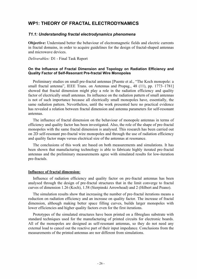
Two pre-fractal monopoles of different fractal dimension in the limit and two non-fractal antennas have been analysed (Fig. 8). The generalized Koch and the wide zigzag configurations, for equal wire length, show longer signal leaps –or shortcuts- than the Koch or the narrow zigzag. The longer signal leaps, the less amount of coupling signal that takes the shortcut, the longer path followed by the signal and the lower resonant frequency.
Benchmarks for pre-fractal antenna performance
In order to develop accurate numerical tools for pre-fractal antennas, well-defined non-fractal benchmarks must be first considered. Two Euclidean structures that have been found to posses properties that were considered exclusive of pre-fractal antennas are the meander printed line and the two-arm spiral.
High-gain localized modes: the meander line The meander-line printed antenna has been carefully studied in order to see if it has high-gain localized modes, like the pre-fractal Koch-island patch, or not. The objective here is to assess if the localized modes are exclusive of pre-fractal structures, or not.
The meander antenna is a rectangular printed patch with N gaps of infinitesimal width parallel to two sides of the rectangle. The N gaps transform the rectangular patch in a line with N meanders.
The meander antenna has been compared with the original patch without the gaps:
At low frequencies, below the patch resonance, the current follows the meander line. The input impedance of the meander behaves as that of the equivalent line. This is useful for antenna miniaturization, because it presents almost the same resonance frequency that unwrapped line and occupies much less space.
At high frequencies (for example 4th resonance of the patch) the meanders couple one with the other and the antenna behaves more like a patch with gaps. Hot spots or “localized modes” appear at the end of the gaps (Fig. 9). The ones at the top of the antenna are in phase, and the ones at the bottom are also in phase, but in counter-phase with the ones at the top.
For higher frequencies complex resonance phenomena appear due to EM coupling between the parallel lines. Further studies are needed in order to understand these complex phenomena.
Resonant frequency
0.3
0.6
0.9
1.2
1.0 10.0 100.0Wire length (cm)
GH
z
Koch D=1.26GKoch D=1.5Zig-zag wideZig-zag narrow
Resonant frequency
0.3
0.6
0.9
1.2
1.0 10.0 100.0Wire length (cm)
GH
z
Koch D=1.26GKoch D=1.5Zig-zag wideZig-zag narrow
Koch D=1.26GKoch D=1.5Zig-zag wideZig-zag narrow
Figure 8: Resonant frequency as a function of the wire length. The antennas have been modeled as extrusion-strips of 1-mm width. Each marker in the plot corresponds to an IFS iteration in the pre-fractal geometries orthe number of meanders in the zig-zags.
Koch K2Generalized
Koch GK1
α
Zig-zag wide Z3
α
Zig-zag narrow z3
α
α

- 33 -
Since localized modes have been known since the 60’s and outside the scope of fractal or pre-fractal structures, we can conclude that localized modes are not exclusive of pre-fractal antennas.
Fig. 9: Higher order mode at the printed meander line antenna. The colour scale shows the phase and the arrow length the magnitude of the imaginary part of the electric current.
Miniature antenna: The two-arm spiral. A study of a two-arm square microstrip spiral antenna backed by a ground plane has been made (Fig. 10).
A spiral presents interesting properties from the geometric point of view, namely self-similarity and infinite length in a finite surface, properties shared by fractal objects. Having chosen a polygonal spiral rather than a Archimedean one is due to the fact that polygonal spiral fits better in a given surface, achieving a more efficient utilization of given area, a principle to take into account when miniaturizing antennas.
Taking as working surface a square of side SL=1.875cm, different iterations of a spiral have been studied and compared with two straight dipole configurations: the dipole of length equal to the unwrapped spiral length and the longer dipole that would fit in the reference square, having as length the diagonal of the square.
Table II shows that the spiral antenna has a resonant frequency almost as low as the straight dipole of same wire length. According to the guidelines derived from the shortcuts
Fig. 10: Current magnitude at the first resonance of a four-turn two-arm spiral antena.
-90
0
90
0 5 10 15 20 25 30 35 40 45 500
5
10
15
20
25
30
35
x [mm]
y [m
m]

- 34 -
or couplings study in preceding section, this is due to the weak electromagnetic coupling between angles, between the feeder and the strip or between parallel strip segments with opposite current. Unlike pre-fractal antennas, the resonant frequency scales almost linearly with the inverse of strip length while keeping the wire enclosed by a small square.
Resonant freq. [GHz] Spiral 4-turns 1.77 Straight dipole
unwrapped spiral 1.6
Straight dipole diagonal 11.6 Table II: Resonant frequency of a 4-turn two-arm spiral, the straight monopole of equal length and the longer monopole that would fit in the reference square
The spiral antenna constitutes a very good benchmark to judge pre-fractal antennas as provides a tough challenge offering excellent miniaturization while keeping a reasonable frequency behaviour.
Task conclusions and design guidelines
• When the number of IFS iterations (order of the pre-fractal) increases beyond a certain threshold, the change in radiation patterns and input impedance of the antenna tends to zero. In other words, there is no use in increasing the number of IFS iterations. Convergence is usually achieved between 4 and 6 iterations. This value depends largely on the size, wire radius or strip width and topology of the antenna.
• The increase of fractal dimension, although making better space filling curves, builds larger monopoles with lower efficiencies and higher quality factors even for the first iterations, at least for wire structures without loops.
• Topology has a stronger influence than fractal dimension on the behaviour of planar pre-fractal wire monopoles, in particular on the losses efficiency.
• When the wire geometry contains no loops, each IFS iteration increases the length and bending of the wires, and as a consequence ohmic losses and the amount of stored energy on the surrounding of the antenna increases (this means lower radiation efficiencies and higher quality factors). While the ratios of miniaturization are remarkable, achieved efficiencies and quality factors are unpractical. The low radiation resistances are due to the presence of anti-parallel currents that cancel the radiation of each other.
• Wire geometries containing loops do not have anti-parallel currents. Although they do not achieve a large degree of miniaturization, as the number of loops inside the structure increases, efficiency and fractional bandwidth (inverse of quality factor) seem to increase with the order of the pre-fractal (number of IFS iterations).
• It has been observed that radiation resistance results are dependent on the length of the feeding segment of the monopole, which seems to be the main source of radiation, while the rest of the structure behaves as a capacitive load that reduces the resonant frequency.
• The hypothesis of electromagnetic coupling –or shortcuts- between corners fully explains why the resonant frequency of pre-fractal antennas is much larger than what could be expected from the wire length only, and why it stagnates as the number of IFS iterations increases.

- 35 -
• As a result of the electromagnetic coupling hypothesis, some guidelines for the design of small antennas have been derived. An antenna design that follows these guidelines, the two-arm spiral antenna, has the smallest possible size for a given resonant frequency.
• The design of wire small antennas using pre-fractal geometries has the advantage of using an easily programmable IFS algorithm to pack a long wire into a given volume. However, the mere fact of being a pre-fractal object does not imply that the degree of miniaturization and antenna parameters are optimum. As in any other kind of antenna, it is in fact the antenna geometry what determines the radiation behaviour. The previous conception that “fractal antenna” is equivalent to “optimum miniaturization and bandwidth” is perhaps a misunderstanding of the well-known Hansen’s statement: “To obtain performance closer to the minimum Q curve the spherical volume must be used more effectively”.
• Some pre-fractal antennas have a slightly smaller electrical size than its conventional counterparts while maintaining their main radiation parameters (quality factor and loss efficiency). This has been assessed for planar monopole configurations.
Guidelines for the design of miniature monopoles As a conclusion of the work in this task and very recent work available in the literature, the following guidelines can established for the design of miniature wire antennas:
4- In order to reduce signal coupling –or shortcuts- between wire angles, the distance between those angles must be as large as possible, and the angles α the larger possible.
5- In order to reduce the signal coupling between the feeder and the wire segments, the most possible wire length must be perpendicular to the electric field radiated by the feeder.
6- In order to reduce coupling between wire segments, parallel wire segments with opposite (anti-parallel) currents very close to each other must be avoided.
An example of wire antenna that closely follows these guidelines is a two-arm spiral. The resonant frequency of a square spiral is inversely proportional to the wire length, while keeping the wire enclosed by a small square.

- 36 -
Task 1.2: Fundamental limits of fractal miniature devices
Objective: Analyse whether the fundamental limit of radiation Q factor of small antennas holds even for fractal structures.
Deliverables: D2 - Final Task Report
Introduction Since the publication of [Puente, 1997], [Cohen, 1997], [Puente, 1998] and [Puente-Baliarda,2000] fractals deserved great attention. The general feeling about the seemingly unlimited potential of these geometries able to reduce their electrical size, and even able to approach their performance to a fundamental limit, was the source of such interest.
In the frame of the Fractalcoms Project, Task 1.2 is essentially addressed to the assessment of how effective is the occupancy of the volume inside the fictitious sphere that encloses a fractal device. This measure of effectiveness is evaluated with the help of a figure of merit called quality factor Q, that is related with the fractional bandwidth of the device.
The closeness of fractal devices to the fundamental limit established decades ago is also analysed and compared with standard Euclidean geometries to check the expectations put on these innovative designs.
Loss efficiency was also an important parameter to study in this task due to the theoretical infinite lengths that designs could reach and their high ohmic losses. Although practical applications pose a technological limitation in the iterative design procedure of these geometries (the intricacy of the shape of antennas and filters is limited), ohmic losses still play an important role on efficiency and insertion losses in these devices.
The existence of less restrictive values for the fundamental limit is explored. A more practical limit comes up after a multi-objective optimisation technique.
Fractal Dimension or Topology Results from Task 1.1 “Understanding fractal electrodynamics phenomena” revealed that fractal dimension does not play a role in the expected improvement of the radiation performance of self-resonant pre-fractal wire monopoles. On the contrary, the use of pre-fractals with large fractal dimension for miniaturizing antennas provides worst performances than certain Euclidean designs. Although increasing the fractal dimension of antennas allows greater miniaturization ratios, poorer values of efficiencies and quality factors are achieved, obtaining unpractical designs for the vast majority of applications. Task 1.1 assessed that like Euclidean antennas, topology is what actually matters when designing an electrically small antenna.
These conclusions are the result from the measurements displayed in Figures 11, 12 and 13. Fig. 11 summarizes the radiation performance of pre-fractal designs according to their fractal dimension and iteration. Their behaviour is compared with several straight monopoles loaded on their top with meander lines. The plot shows that better performances are achieved with the Euclidean monopoles for the same electrical size at resonance.
Figures 12 and 13 show the behaviour of several pre-fractals (with fractal dimension 1.58 and 2, respectively) generated with the same Iterative Function System (IFS) algorithm but with different initiators. Both figures agree in the fact that bending a continuous wire is suitable to reach greater miniaturization ratios. However, the radiation
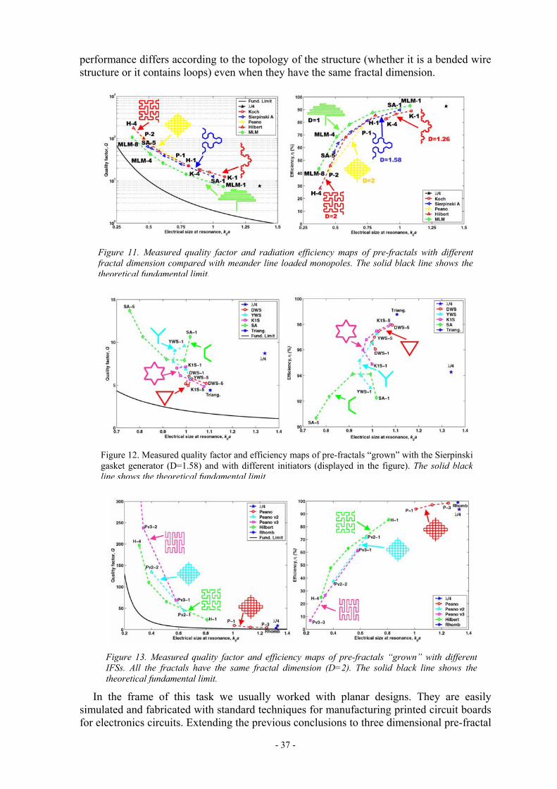
- 37 -
performance differs according to the topology of the structure (whether it is a bended wire structure or it contains loops) even when they have the same fractal dimension.
In the frame of this task we usually worked with planar designs. They are easily simulated and fabricated with standard techniques for manufacturing printed circuit boards for electronics circuits. Extending the previous conclusions to three dimensional pre-fractal
Figure 11. Measured quality factor and radiation efficiency maps of pre-fractals with differentfractal dimension compared with meander line loaded monopoles. The solid black line shows thetheoretical fundamental limit.
Figure 12. Measured quality factor and efficiency maps of pre-fractals “grown” with the Sierpinskigasket generator (D=1.58) and with different initiators (displayed in the figure). The solid blackline shows the theoretical fundamental limit.
Figure 13. Measured quality factor and efficiency maps of pre-fractals “grown” with differentIFSs. All the fractals have the same fractal dimension (D=2). The solid black line shows thetheoretical fundamental limit.

- 38 -
designs should increase the effects of enlarging wire lengths and storing electromagnetic energy in the vicinity of the antenna. Therefore, efficiency and fractional bandwidth will decrease faster for these pre-fractal designs than for planar monopoles. These expectations have been proved after the analysis of a three dimensional Hilbert monopole (see Deliverable D1 “Task 1.1 Final Report”).
The practical bandwidth limit In previous sections we have seen that the fundamental limitation used in practice as a reference is far from the limit obtained with actual designs, either Euclidean or fractal. Therefore, it would be useful to determine more realistic limits for antennas. We have chosen to apply an heuristic mathematical method to obtain extrema and to asses whether Euclidean geometries are capable of combining miniaturization and closeness to the fundamental limit.
In particular we wanted to obtained a more realistic practical limit for the Q value of small antennas and to compare it with the theoretical one given by Chu. With this aim a multi-objective Genetic Algorithm (GA) tool has been applied in conjunction with the numerical electromagnetic code (NEC) to the optimisation of wire antennas in terms of the Q factor, but having at the same time a small electrical size and high efficiency.
Planar meander line and zigzag type monopoles (restricted to 12 wire segments) inscribed into an hemisphere of fixed radius (Fig. 14) have been designed using the previously described multi-objective optimisation technique based on GA. Electrical size at resonance, efficiency and quality factor are the parameters that manage the evolution of the algorithm. Both types of monopoles are chosen because of their checked suitability to fabricate miniature antennas. After the optimisation procedure, a set of optimum solutions (that survived the evolutionary procedure of optimisation) have been found by the algorithm. The Pareto front of this set of solutions is a surface that is displayed in Figure 15, where the expected performance of each design is shown in terms of SWR versus the resonant frequency and the wire length of each antenna. In order to facilitate the visualization and understanding of the results we just plot, in Figure 16, the efficiency and Q factor of a set of individuals selected from the Pareto surfaces. In particular the individual with a lower Q has been chosen.
Figures 15 and 16 provide a practical limit more realistic than Chu’s for the design of small antennas that fits in the half circle of radius a and in the range of frequencies analysed. The results show that the miniaturization of the antenna (the reduction of its electrical size ka) is translated into a worsening its radiation performance: efficiency and fractional bandwidth decrease reaching unpractical values for the vast majority of common applications. Although their radiation pattern and directivity remains unchanged, the loss efficiency of the structures reduces enormously the gain of the designs.
Figure 14. Example of meander and zigzag type antennas. The dotted black lines show thevalues of wire segments lengths.

- 39 -
The Pareto fronts in Fig. 16 (gren and blue lines) represent the best performance that a planar self-resonant wire monopole can reach, that is, the practical bandwidth and efficiency limitations. The theoretical fundamental bandwidth limit (black line) is far away. Fig. 16 also includes a plot of the performance of a Hilbert planar monopole for iterations 1 to 4 (red line), to show their closeness to the practical limits for efficiency and quality factor.
All the results displayed in the plots have been computed for designs with the same wire radius. Slightly more efficient designs are expected by increasing the wire radius of the antennas. Obviously this improvement is expected both for the Euclidean and the pre-fractal monopoles.
A recently published paper [Thiele, G.A., Detweiler, P.L., Penno, R.P.: “On the lower bound of the radiation Q for electrically small antennas”, IEEE Transactions on Antennas and Propagation, June 2003, 51, (6), pp. 1263 –1269] estimates a more realistic lower bound for the fundamental limit on the radiation Q. This prediction is based in the assumption of a sinusoidal current distribution along an electrically small antenna, in contrast with the classical Chu and McLean approach where an Hertzian dipole with a
Figure 15. Pareto front of a multi-objective optimisation.
Figure 16. Quality factor (left) and efficiency (right) plots for a set of individuals with lower Qextracted from the Pareto front. Both are compared with the performance of a planar Hilbertdesign.

- 40 -
uniform current distribution was considered. Fig. 17 shows that the practical bandwidth limit found in this task agrees very well with the new theoretical limit recently found by Thiele et al.
Task conclusions
• It has been empirically assessed that the fundamental Chu limit of radiation quality factor of antennas holds even for pre-fractal devices. Moreover, pre-fractals are not closer to this borderline than other standard Euclidean designs.
• A multi-objective optimisation technique based on Genetic Algorithms (GA) assessed the existence of practical limits more restrictive than the fundamental limit predicted by Chu and reviewed by McLean. Both Euclidean and pre-fractal geometries are near this practical limit. The limit has been found for planar self-resonant wire monopoles. A closer practical limit could be found if three dimensional self-resonant monopoles would have been analysed.
• A more realistic limit that holds for antennas with sinusoidal current distribution has been recently published [Thiele, 2003]. The practical bandwidth limit found in this task agrees very well with the new theoretical limit recently found by Thiele et al.
Figure 17. Fundamental limit of radiation Q for a sinusoidal current distribution (black continuousline) along a wire. This limit is compared with the classical limit by Chu and McLean (black dashedline). Both limits are compared with measured lossless Q of pre-fractal monopoles of differentfractal dimension (left plot) and computed Q of genetically designed planar monopoles (right plot).

- 41 -
WP2: VECTOR CALCULUS ON FRACTAL DOMAINS
Task 2.1: Solution of EM simple problems on fractal domains
Deliverables: D3 - Final Task Report
a) Connection between the topological formulation of field equations on simplicial complexes and the continuum limit.
The analysis electromagnetic fields on fractal supports leads to a topological formulation of the Maxwell equations. Since the domain in which the electromagnetic field propagate is fractal, the main issue is to reformulate the field equations in a way suitable to be applied for fractal lattices. This problem is extremely interesting for its physical and mathematical implications, but is rather aside the straight applications in engineering electromagnetic problems, especially as it regards antenna design. We think that this approach is not essential for the solution of antenna problems involving fractal structures. For that reason, the ROME reports corresponding to task 2.1 (Deliverable D3 and the Annex to this progress report) have reviewed the central ideas of this approach, without entering into the more technical details associated with the theory.
b) Solution of paradigmatic examples of electromagnetism in the presence of fractal structures
These problems involve the representation of sources radiating in free space and defined on fractal boundaries, which can be tackled by means of the formal apparatus developed in WP2 Task 2.2 (see Deliverable D4 and Annex to this progress report). This class of problems encompasses all the direct and inverse problems in antenna theory. The radiation problem of an antenna can be tackled by expressing the vector potential with respect to a current source distribution localized on a fractal support, the estimate of which can be obtained by solving the corresponding electromagnetic integral equation on a fractal support. The main issues are in this case the representation of scalar and vector fields on fractal structures, the setting of the integral equations on fractals and their solutions.
In the first place, direct electrostatic problems on fractals have been solved. By direct problems we mean that either the electric charge density or the electric current density are specified on a given structure. The classical integral equations involving charge/current density and scalar/vector potentials have been reformulated for fractal structures. The electrostatic potential of both a uniform and non-uniform parameterised charge distribution on a Koch curve and a non-uniform charge distribution within a Sierpinski gasket have been obtained.
In the second place, the solution of inverse electrostatic problem is addressed. Essentially, the inverse problem can be stated as finding the charge distribution on a fractal structure that produces a given scalar potential. It has been observed that, as the number of IFS iterations increases, the charge density –solution of the inverse problem- becomes a multifractal measure in the limit. Conversely, the charge measure –integral of charge density along the fractal curve- converges towards an invariant shape as the number of iterations increases.
The conclusions are:
The charge density on a fractal structure displays a highly singular structure (resembling a multifractal measure). This is explained intuitively since fractal conductors display corners at all the lengthscales, and the singularity in the charge distribution reflects the presence of them.
- 42 -
The solution of the inverse problem is well posed in terms of a charge measure rather than by enforcing charge densities. A limit charge measure, solution of the inverse electrostatic problem is numerically attained after few iterations in the construction process of the fractal structure.
The highly singular structure of the charge measure prevents the use of collocation approaches for numerical discretization, since they make use of localized functions.
The behaviour of pre-fractal capacitors have been analysed as a function of the spacing between the two plates, and have been compared with the behaviour of parallel-plate condensers. Specifically, for the third iterate in the generation of the modified Koch curve, the fractal capacitor holds a much larger (factor larger than 8) overall charge than a Euclidean one, possessing the same overall end-to-end length.
In the third place, the fully vector radiation problem is addressed. The vector potential and the radiation pattern have been obtained for uniform and sinusoidal current distributions on modified Koch pre-fractal antennas after 3 to 5 IFS iterations. It is remarkable that the radiation pattern converges towards a limit just after a few iterations.
Task 2.2: Formulation of EFIE on fractal domains
Deliverables: D4 - Final Task Report
In this task, the formal mathematical apparatus for setting the integral equations of applied electromagnetics on fractal curves has been provided. The analysis starts from the parametric representation of fractal curves through Augmented IFS (AIFS), defines the concept of tangential sign measures, and develops the formulation of contour integrals over fractal curves through the use of these quantities.
Subsequently, the formulation of EFIE on fractal wire antennas has been developed using the thin-wire Pocklington equation. The numerical solution by method of moments has been thoroughly addressed. The extension of EFIE to more general fractal sets has been addressed by defining a parametrization of the fractal support through the use of space-filling curves.
These results are important because they represent a first systematic attempt towards a formulation of a vector field theory in true fractal domains in order to solve inverse electromagnetic scattering problems through EFIE on mathematical fractal supports, and not solely on finite approximations (pre-fractals) of the structure. This is, to our knowledge, the first theoretical formulation of the EFIE describing wire antennas on a fractal support, and is a significant improvement of the ideas and of the approaches proposed in a recent past by the members of the ROME group.
From an antenna engineering point of view, one of the most important results of task 2.2 is the following: In a pre-fractal structure generated by an IFS, when the number of iterations increases, the direction of the current flow changes many times inside a reduced volume. These rapid current variations do not converge with the number of iterations and are very difficult to model for point-based methods used to discretize the Electric Field Integral Equation (EFIE). However, the radiated field and input impedances are computed though a integration, or averaging, of the antenna current.
In this workpackage, the ROME group has demonstrated that the integrals of the current or charge along the pre-fractal antenna show a very fast convergence with the number of iterations. This has two consequences:

- 43 -
1. When the IFS iteration number increases beyond a certain threshold, the change in radiation patterns and input impedance of the antenna tend to zero. In other words, there is no use in increasing the number of IFS iterations. Convergence is usually achieved between 4 and 6 iterations. This value depends largely on the size and topology of the antenna, as can be demonstrated by the theory of mutual interaction between corners (suggested by UPC and numerically verified by UGR, see annexes WP1 T1.1 UPC Koch and WP3 T3.4 UGR to this T0+6 progress report).
2. The Galerkin (or weak) formulation of method of moments is the most convenient approach to discretize EFIE of fractal supports rather than point-based approaches like collocation and Nystrom methods. This is due to the fact that on a fractal structure it is not possible to enforce the boundary conditions in a point-wise way, while it is possible in a measure-theoretical (integral) sense, by making use of the tangential sign measures.
The ROME group suggests, as a first approach, the discretization of Pocklington EFIE using global (non-localized) basis functions in order to reduce the computational complexity.
The results so far obtained define the pathway and the program for the future research activity that will be performed by the ROME group within the FRACTALCOMS project, which will be oriented on the numerical application and exploitation of the theoretical tools described in this report by extensive simulation of EFIE for fractal wire antennas.
The use of a parametric representation of more complex geometrical sets through a space filling curve on them, coupled with the formulation of EFIE on fractal curves provides an interesting research field that will be also analyzed by means of numerical simulations by the ROME group in the remainder of FRACTALCOMS project.

- 44 -
WP3: SOFTWARE SIMULATION TOOL
Task 3.1: Advanced meshing of fractal structures
Deliverables: D5 - Final Task Report
Objective: This task is essentially aimed at developing special purpose meshing tools for the numerical simulation of pre-fractal structures, so that the aims of this project can be reached. The work to do in this task is, from Annex-1 to the contract between the consortium and the EC:
a) A high-order point-based discretization scheme based on Nystrom method with singular kernel correction will be explored.
b) Advanced adaptive meshing facilities will be developed for fractal domains. In a first phase, conventional meshing algorithms will be adapted to the requirements of the present project. In a second phase, the production of fractal meshes for the discretization of fractal domains will be evaluated and, if possible, the corresponding algorithms will be developed and coded.
c) New basis functions for vertex-connected structures will be introduced.
d) Specific treatment of T-junctions and similar complex connections will be provided.
Nystrom method high-order discretization scheme
Formulation and software code has been developed for the analysis of electrostatic problems with potential equation and Nystrom method. The kernel singularity has been corrected by Strain’s method, using polynomial testing functions. The charge is therefore represented by a underlying polynomial basis. The results for objects with open surfaces are very bad, since the charge is singular at edges and cannot be expanded by the underlying polynomial quadrature basis. On the contrary, when the unknown charge is a polynomial, Nystrom method gives very small errors, up to machine precision.
Close form formulas for evaluating the integrals that arise in the computation of Strain correction have been derived for problems with singular kernel and polynomial unknown. However, it has not been possible to derive Strain correction formulas for problems having both singular kernel and unknown. Problems of this kind are the Electric Field Integral Equation (EFIE) and the electrostatic potential equation on open surfaces. For that reason, Nystrom method can be currently applied to electromagnetic problems only on closed surfaced, which is not the case of the antennas under consideration.
For those reasons, Nystrom method is not adequate for the analysis of pre-fractal antennas, since:
• Nystrom method is based on quadrature integration rules that relay in underlying polynomial basis. Since the rapidly varying -almost discontinuous- current and charge in pre-fractals cannot be expanded by a polynomial basis, Nystrom method looses its power of accurate integrations with few samples and results will be very poor.
• Nystrom method forces the EFIE equation in a point-matching fashion. Since the near field is also rapidly-varying, it is best to use a weighted residual procedure such as method of moments.
On the other hand, since the integrals of the current or charge along pre-fractal antennas converge very fast with the number of iterations (result of WP2 and Task 3.2), then it is

- 45 -
possible to discretize the EFIE in highly-iterated pre-fractals using the conventional Galërkin - Method of Moments, which is in essence a weighted residual procedure.
In conclusion, we think that the Method of Moments with Galërkin testing (weak formulation) is the most robust approach to discretize the EFIE in pre-fractals. This assumption has been corroborated by the excellent results of numerical simulations in tasks 3.2, 3.3 and 3.4.
Modeling pre-fractal antennas
Modeling highly-iterated pre-fractal wire antennas is a challenging problem. It has been shown in [Deliverable D6, Task 3.2 Final Report] that several difficulties arise with Pocklington integral equation and thin-wire models, even with the extended kernel.
The possibility of modeling the wire cylindrical surface with a triangle mesh is not practical do to cylinder intersections at corners, the huge computational cost required and, in difficult problems, there is no convergence with mesh refinement.
For that reason, we propose here to model pre-fractal wires using a narrow strip. Two strip models are considered: the planar and the extrusion strip (Fig. 18). Both lead to similar results for low-iteration pre-fractals, but the extrusion strip, unlike the planar one, can model highly-iterated pre-fractals in which the strip width is comparable to the pre-fractal segment length (Fig. 19).
For both kinds of strips, the discretization in triangles of size much smaller than the wavelength makes the linear system very badly-conditioned. For that reason, iterative solvers fail, even with huge pre-conditioners. A direct solver can be used with more than 10,000 unknowns thanks to the block-solution algorithm developed at UPC.
A numerical integration and mesh refinement convergence study has been done. The extrusion strip model shows good convergence with both refinement of mesh size and refinement of EFIE source and testing integration, for both the cases of electrically very small and self-resonant antennas.
Figure 18: Koch pre-fractal monopole of 1 iteration modeled as planar strip (a) and an extrusion strip (b).
a) b)

- 46 -
Meshing pre-fractal antennas
Software facilities have been developed in order to mesh a wide range of fractal geometries in the most automatic and adaptive way with while keeping the user interaction to a minimum.
The starting point of this task is the commercial pre and post-processing software package named GiD that has been developed at CIMNE. This software has been developed for giving support to all the necessary operations for the preparation of data for numerical analysis involving any type of geometrical discretization of the analysis domain, like in the case of the numerical algorithms used in the FRACTALCOMS project. Since standard CAD systems are not prepared for the generation of fractal geometries, the main activity in Task 3.1 has consisted in providing GiD with new software facilities for the automatic generation and meshing of fractal geometries. In addition, special adaptive mesh facilities have been added to the software in order to allow an enhancing of the quality of the numerical results in certain areas of the analysis domain.
The main technical aspect of the new tools added to GiD for the generation and meshing of fractal geometries is the recursive definition of the fractal geometry. Following the indications from UPC, this definition is based in the use of a geometrical Initiator and a geometrical Generator. The generation of the fractal geometry is based on a recursive process in which each segment of the Initiator is substituted by the Generator. Both the Initiator and the Generator can be selected from an existing list or manually defined by the user (Fig. 20).
If the thin-wire approximation is not used, the recursive definition of the fractal geometry produces a wire antenna that needs to be widened in order to get a strip. This process is produced by widening each linear segment of the obtained geometry. Special care has to be taken in order to avoid overlapping between strips from consecutive segments at the corner points. This process is executed automatically after defining the with of the strip antenna.
Resonant frequencies
0.7
0.8
0.9
1
1.1
1.2
K0 K1 K2 K3 K4 K5
IFS iterations
GH
z
Resonant frequencies
0.7
0.8
0.9
1
1.1
1.2
K0 K1 K2 K3 K4 K5
IFS iterations
GH
z
1 mm planar-strip
Strip width
2 mm extrusion -strip 0.5 mm extrusion -strip
1 mm extrusion-strip
0.5 mm planar-strip Figure 19:Resonant frequency of 6cm-height Koch monopoles made of planar and extrusion strips of differentwidths. The planar models depart from the expected pre-fractal behaviour when the number of IFS iterations increases.
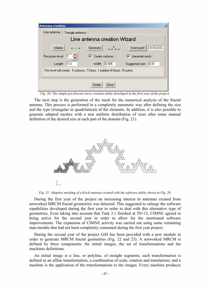
- 47 -
Fig. 20: The simple pre-fractal curve creation utility developed in the first year of the project.
The next step is the generation of the mesh for the numerical analysis of the fractal antenna. This process is performed in a completely automatic way after defining the size and the type (triangular or quadrilateral) of the elements. In addition, it is also possible to generate adapted meshes with a non uniform distribution of sizes after some manual definition of the desired size at each part of the domain (Fig. 21).
Fig. 21: Adaptive meshing of a Koch antenna created with the software utility shown in Fig. 20.
During the first year of the project an increasing interest in antennas created from networked MRCM fractal geometries was detected. This suggested to enlarge the software capabilities developed during the first year in order to deal with this alternative type of geometries. Even taking into account that Task 3.1 finished at T0+12, CIMNE agreed in being active for the second year in order to allow for the mentioned software improvements. The expansion of CIMNE activity was carried out using some remaining man months that had not been completely consumed during the first year project.
During the second year of the project GiD has been provided with a new module in order to generate MRCM fractal geometries (Fig. 22 and 23). A networked MRCM is defined by three components: the initial images, the set of transformations and the machines definitions.
An initial image is a line, or polyline, of straight segments; each transformation is defined as an affine transformation, a combination of scale, rotation and translations; and a machine is the application of the transformations to the images. Every machine produces

- 48 -
its own image, operating not only on its own image, but also on all images of the other machines in the network. Here we also call ‘generators’ to the machines.
Figure 22: Software utility to create networked MRCM pre-fractal geometries.

- 49 -
Figure 23: Two examples of networked MRCM pre-fractal antennas created and meshed with the new GiD module: Hilbert (left) and Twig (right) antennas.
New basis functions
EPFL partner has developed a new set of basis functions defined on quadrangular regions (see example in Fig. 24). Particular cases of these functions are the well-known rooftop and Rao, Wilton and Glisson (RWG) basis.
These new functions will be very useful for the project because they simplify enormously the electric connection between different patches of the pre-fractal that share only one vertex. As a result, it will be easier to build adaptive meshes having less unknowns and modeling better the variation of the current in the pre-fractal geometry.
Three cases of quadrangular basis functions have been considered:
With constant normal component of the current at one edge. The divergence of the current (charge) is not constant.
With constant divergence of the current, but non-constant normal component of the current at the edge.
Having both properties of constant divergence of the current and constant normal component of the current at one edge.
The best results are obtained with the 3rd option. The agreement with the conventional rooftop and RWG functions is very good.
The potential of quadrangular basis functions for solving connectivity problems has been shown in the simulation of a bow-tie antenna with different feeding zone sizes. The results are very promising.
Figure 24: Bow-tie antenna meshed withquadrangular basis functions.

- 50 -
Treatment of T-junctions
When building prefractal antennas of intricate shape (Koch, fractal tree) with microstrip or printed technology, discontinuities such as right-angle bends, T-junctions and crossings are encountered. In a boundary element discretisation, brute force approach would require an important computer effort and time for such complicated structures and would prevent us to analyse but the very first fractal iterations. Knowing the electromagnetic behaviour of these connections (mainly the distribution of currents and charges), a model could be created in order to substitute a brute force discretisation in the junctions. In the present work, a study of currents and charges in a T-junction is done in order to know which kind of global basis function would serve best as model for this type of junctions. This global basis should allow us to analyse pre-fractal antennas up to the iteration limit imposed by current technology.
Different models for analysing printed junctions have been discussed. First, the quasistatic model has led us to two results, namely: The current distribution tends to be solenoidal at low frequencies and Kirchoff’s law should be satisfied in small junctions. Then a transmission line (TL) model has been studied to have some useful global indications about the charge and current behaviour. In this case Kirchoff’s law must still be satisfied but opposite to quasistatic approaches, the TL model allows prediction of charge behaviour in the arms connected at the junction. Indeed the TL predictions are frequently a good approximation at the global level.
These global results have been corroborated with a full-wave model. For low frequencies the general behaviour of charge and current along the line for the transmission line model and in the full-wave model is the same, except, of course, in the junction. For high frequencies radiation phenomena take place, and so transmission line model is no longer valid. But even at low frequencies, radiation is generated at the junction. This results in a net decrease of charge level at the junction which has been systematically observed in our numerical experiments. This feature of the charge must be included in the pre-fractal antenna model if accurate predictions are required.
Fig. 25: Magnitude of charge in a T junction of a H-tree pre-fractal antenna.
With the full-wave model the structure has been studied once with a rough mesh and once with a very high number of unknowns, to know in detail which is the evolution of currents and charges on the T-junction, for different kind of excitation. With a high degree of detail results show with precision the zones where current and charge maxima or minima can be found. For low frequencies, in the junction and without taking into account

- 51 -
singularities, the charge can be said to be constant, but it is no longer the case for high frequencies. All this information must be used in order to define a global basis function that reproduces these characteristics, and thus it can be used to substitute the detailed fine mesh in the junction without loss in precision and accuracy of results.
Summarizing, this study has set up the basic strategy for the modelling of connections and junctions in pre-fractal antennas. Some observed effects deserve further study in order to reach a correct interpretation. For instance the electromagnetic behaviour of junctions seems to depend critically on the kind and type of excitation.
At a first glance, this seems to render hopeless a global, unique approach for junctions in fractals. But save for the case of a junction containing eventually the excitation, most junctions in fractal structures are essentially excited by the fractal itself and hence there is room for a systematic time-saving treatment.
Task 3.2: Formulation of numerical methods for fractal structures
Deliverable: D6 – Final Task Report
This task is essentially aimed at analyzing critically the problems associated with the numerical simulations of fractal structures based on the results achieved in Tasks 2.1 and 2.2, and at developing efficient computational approaches for a reliable numerical simulation of high-order iteration prefractal wire antennas using the Electric Field Integral Equation (EFIE). It was agreed in the Kick-off meeting that the research would be concentrated in wire antennas, that can be either a cylindrical wire or a strip.
Three main items have been addressed:
Validity of the thin-wire approximation:
The accuracy of the commonly used approximations for the analysis of thin-wire antennas when applied to fractal structures has been evaluated. It is concluded that:
• The thin-wire kernel of the Electric Field Integral Equation (EFIE) can be used in low-iteration pre-fractals without introducing significant errors. Examples of computer codes based on thin-wire approximation that have been used in this project are: DOTIG (time domain), NEC (frequency domain) and FIESTA (frequency domain).
• When the EFIE is discretized by Method of Moments in subdomain basis functions, the thin-wire kernel with or without equivalent radius produces important errors in the computation of highly iterated pre-fractal antenna parameters, since the pre-fractal curve segments become comparable to the wire diameter. Even the full kernel fails because the assumption of constant current along the wire circumference is no longer valid and the wire cylindrical segments overlap at corners. A extrusion strip can be used in this case in order to obtain an accurate subdomain discretization of the EFIE.
• The results of extrusion strip models computed with FIESTA code have been compared with the simpler thin-wire models. The comparison results fully support the conclusions above (Fig. 26).

- 52 -
Implementation of wire antenna analysis in FIESTA computer code:
The computer codes for the analysis of wire antennas available at the start of FractalComs project, namely DOTIG and NEC, do not use advanced techniques for the solution of very large systems of equations. On the other hand, FIESTA code is able to solve the EFIE with hundreds of thousands of unknowns, but at the project start date only the analysis of perfectly conducting surfaces was implemented.
In order to solve very large wire antenna problems, the Electric Field Integral Equation for wires has been implemented in FIESTA. Thee different formulations of the kernel have been programmed: thin-wire, thin-wire with equivalent radius and full kernel.
The full kernel has been implemented using a new approach that allows computation in a run time only twice the time required for the much simpler thin-wire approximation. The new approach is based in a polynomial approximation of the 2-D integrals that arise from the full-kernel formulation, and is valid for segment length to segment radius ratios larger than 10-4. Previously, the evaluation of the full-kernel base on series expansions of the integrand was cumbersome and computationally expensive.
Koch monopole: Comparision of different wire models
0.75
0.8
0.85
0.9
0.95
1
1.05
1.1
1.15
1.2
1.25
K-0 K-1 K-2 K-3 K-4 K-5
IFS iterations
Res
onan
t fre
quen
cy (G
Hz)
NEC extended kernelFIESTA thin-wire kernelFIESTA extended kernelFIESTA extrusion strip
Figure 26: Resonant frequency of a 6cm-height Koch monopole of 1 to 5 IFS iterations, computed using different formulations of the EFIE. Only the surface formulation with a extrusion-strip mesh shows the expected behaviour for a pre-fractal structure. The thin-wire approximation fails for highly iterated structures.

- 53 -
New approaches for solving the EFIE of wire antenna analysis:
Some numerical approaches based on the Galërkin-Petrov expansion for solving the EFIE in pre-fractal structures have been studied. The approach proposed proves to be very versatile and computationally efficient. Particular attention is oriented towards the analysis of the thin-wire approximation from the numerical point of view, by discussing critically its validity and pitfalls, in the light of the compactness property of the associated linear operator. Numerical simulations have been performed on different pre-fractal structures, highlighting some interesting properties of the current profiles.
It is clear from the analysis developed in WP2 that any numerical simulation of the EFIE equations on fractal structures cannot be conveniently grounded on point-matching approaches, but should be framed within a weak-formulation of the EFIE resulting from a Galërkin-Petrov expansion in a basis of entire-domain functions. The proposed technique is therefore based in the Method of Moments Galërkin discretization of the Pocklington thin-wire kernel in a set of complete-domain sinusoidal basis functions.
Although the Pocklington equation for dipolar antennas has been known and widely used for a long time, the computational issues associated with the analysis of thin wires are still an open problem. Recent articles conclude that the thin-wire approximation gives rise to an “ill-posed problem”, and that all the simulations based on this approach are scientifically unreliable.
Since the thin-wire approximation is one of most useful simplifying assumptions in applied electromagnetism, we have analyzed very carefully this issue, and we have shown that, albeit the criticism of some authors is motivated by a correct mathematical observation, in practical problems involving thin-wire antennas the entire-domain Galërkin approach furnishes reliable and convergent approximations for the computation of the current and the antenna parameters.
Of course, the numerical problems are much more delicate in dealing with fractal wire antennas, since the geometric complexity of the structures is superimposed to the intrinsic difficulty of handling a singular integral equation.

- 54 -
Task 3.3: Simulation of fractal structures in the frequency domain
Objective: The presently available software packages for electromagnetic simulation in the frequency domain will be upgraded to analyze fractal structures, with emphasis in wire, planar and microstrip antennas. Since most simulations will require the solution of huge full-matrix linear systems of equations, the efficient methods (MLFMM, MLMDA, SMA) already developed by partners UPC and EPFL can be upgraded for the analysis of fractal devices.
Deliverables: D7 Final Task Report
The aim of Task 3.3 is to support all the other tasks of the project through computer simulations of antenna parameters. The results of the simulations are shown in the corresponding task final report deliverables.
Task 3.3 was originally scheduled to start at T0+6. However, in the kick-off meeting it was decided that task 3.3 started at T0 because UPC was interested in developing algorithms to reduce the computational cost of pre-fractal antennas simulation in the frequency domain.
The numerical methods used for antenna simulations at different groups are:
UPC: Surface Electric Field Integral Equation discretized by Method of Moments with
Rao-Wilton and Glisson bi-triangular basis functions and free-space Green’s function.
Thin-wire Electric Field Integral Equation discretized by Method of Moments with linear basis functions and full-kernel evaluation.
The UPC code, FIESTA (“Fast Integral Equation Solver for scaTTerers and Antennas”) has a very efficient iterative solver with multilevel algorithms to achieve a computation time per iteration proportional to N log2 N, where N is the number of unknowns. In order to solve ill-conditioned systems of equations, FIESTA has an in-house developed block-LU decomposition algorithm that allows both the use of huge pre-conditioners in the iterative solver and the direct solution of systems of equations having more than 10,000 unkonws.
EPFL: Surface Electric Field Integral Equation discretized by Method of Moments with
rooftop and quadrangular basis functions (see Task 3.1 final report, deliverable D5) and multilayer Green’s function with Sommerfeld integral evaluation.
UGR: NEC public domain code, with thin-wire Electric Field Integral Equation
discretized by Method of Moments and enhanced kernel evaluation.
Multiobjective optimization Genetic Algorithms (GA) have been used to find the optimum values of antenna parameters in task 1.2 (see Task 1.2 final report, deliverable D2).

- 55 -
The two new approaches for the analysis of pre-fractal antennas that have been developed at UPC are:
• Optimisation of iterative solver multilevel algorithms to take advantage of the multilevel structure of pre-fractal geometries defined by an IFS.
• Development of a new formulation for a fast evaluation of the full-kernel in the thin-wire Electric Field Integral Equation, in order to allow its application to highly iterated wire monopoles.
Optimisation of iterative solver multilevel algorithms
The numerical analysis of highly iterated pre-fractal antennas by Method of Moments (MoM) involves many tiny subdomain basis functions, resulting in a very large number of unknowns. When these antennas can be defined by an Iterated Function System (IFS), the geometry has a multilevel structure with many equal subdomains. This property, together with a Multilevel Matrix Decomposition Algorithm (MLMDA) implementation in which the MLMDA blocks are equal to the IFS generating shape (Fig. 27), has been used to reduce the computational cost of the numerical simulation of a Sierpinski based structure.
It has been shown that the combination of the GMRES and the MLMDA scheme, together with the appropriate choice of the shape of the boxes in the multilevel subdivision, leads to a very efficient solution. Our best implementation produces a reduction by a factor of 20 in the total computation time and a factor of 10 in the total memory, compared with a direct application of MoM (Table III).
MoM+GMRES GMRES+MLMDA optimized
Memory Time Memory Time 4 it., N=568 5.3 MB 5 s. 1.8 MB 1.1 s. 5 it., N=1702 48.0 MB 25 s. 7.9 MB 4.1 s. 6 it., N=5104 424.8 MB 219 s. 39.6 MB 25 s. 7 it, N=15310 - - 166.5 MB 176 s.
Table III: Computational requirements to analyze the Sierpinski antenna with the conventional method ofmoments (MoM) and an iterative solver compared with the optimized approach developed in this project.
Figure 27: a) Multilevel decomposition for arbitrary shapes. b) Multilevel decomposition for IFSgenerated fractals: while boxes do not overlap and cover the whole geometry of the antenna, they can beof the same size and shape as the IFS building blocks. This decomposition produces many pairs of sourceand field boxes with the same interaction matrices.
LEVEL
2
LEVEL
1 LEVEL
3a) b)

- 56 -
Efficient evaluation of the full-kernel of thin-wire EFIE
The thin wire model in computational electromagnetics is used for problems that can be modeled as a set of electrically thin cylinders, referred to as wire segments. The wire segments are assumed to be sufficiently thin for the following conditions to hold:
1. Only the axial components of the induced surface current and the incident field need to be considered.
2. Both the induced surface current and the incident field are constant along the wire circumference.
Under these conditions, the surface current can be expanded in one-dimensional local basis functions for use in the Method of Moments (MoM). In the MoM, the mutual impedances of all the wire segments must be evaluated. This involves the integration of the basis functions and their divergence over the wire surface, with a kernel given by the appropriate Green's function.
If the wire radius a is small compared to the segment length ∆, then an efficient evaluation of this integral is possible using an approximation of the Green's function called the reduced kernel or thin wire approximation. However, there are some problems of practical interest, like highly iterated fractal antennas, in which the model contains short and thick segments, and therefore the thin-wire approximation cannot be rigorously applied.
On the other hand, the integral with the full kernel is valid for any segment length / radius ratio, but it has no analytical solution and solving it by numerical integration is computationally expensive, particularly for the self-impedance of the wire segments, for which the kernel is singular. Several approaches have been presented in literature for the evaluation of the full kernel. The series approach in the extended kernel of the public domain computer program NEC-2 is limited to ∆/a>2. More recently, series representations have been presented that are valid without restrictions on ∆/a. However, for small ∆/a these series show slow convergence.
Task 3.2 “Formulation of numerical methods for fractal structures” showed that the thin-wire reduced kernel of the Electric Field Integral Equation can be used only in low-iteration pre-fractals. Highly pre-fractal wire antennas must be either modeled as a extrusion strip or analyzed using the full-kernel instead of the reduced kernel in the thin-wire Electric Field Integral Equation.
In this task, a new formulation has been developed in order to achieve a very fast evaluation of the full kernel. The computation time if roughly twice the time required for the evaluation of the reduced kernel and the presented formulation is valid for any ratio of the wire segment length ∆ to the wire radius a, and anywhere in space, including on the wire surface. Convergence down to ∆/a∼10-4 has been observed, including the usually difficult case of the self-impedance term.
Table IV shows the radiation resistance of a 5-iteration Koch monopole, 6cm height and (1/π) mm radius. The conventional thin-wire reduced kernel results are clearly wrong. The thin-wire with full kernel approach developed in this task agrees very well with the surface formulation of the EFIE using a extrusion strip that, according to the results of Tasks 3.1 and 3.2, can be taken as a reference. The main advantage of the thin-wire full kernel approach over the 2-D formulation is that computation time is very small, since the 1-D discretization requires only 4096 unknowns, while the 2-D mesh has 22,524 unknowns.

- 57 -
Method Rr Unknowns
Thin-wire with reduced kernel 0.07 Ω 4096
Thin-wire with full kernel 18.1 Ω 4096
Surface EFIE with 2 mm extrusion strip 18.6 Ω 22,524 Table IV: Radiation resistance at the resonant frequency of a 5-iteration Koch monopole, 6cm height and (1/π) mm radius.
Task 3.4: Simulation of fractal structures in the time domain
Objective: Electromagnetic simulation in the time domain is essential for visualization and physical interpretation of electromagnetic phenomena, such as radiation, scattering and diffraction. The results from this workpackage will provide and invaluable feedback to WP1:
a) Time-domain simulation software already developed by partner UGR for wire and planar conventional antennas will be upgraded for the analysis of fractal structures.
b) Animated time-domain simulation of the structures proposed in WP1 and WP4.
Deliverables: D8 Final Task Report
Simulations in the time domain allow to isolate interactions using time range (cause and effect can be distinguished providing an easier physical interpretation of the results), to simulate transient phenomena, to visualize the time history of the physical magnitudes and have the possibility of obtaining, in a single program run, broadband information.
UGR group has a home-developed code Method of Moments in the time domain (MoM-TD) code, DOTIG, that is as an excellent tool for the visualization of electromagnetic scattering and radiation phenomena. In order to analyse the complex antennas subject of FRACTALCOMS project, DOTIG has been extended in with:
Non-uniform segmentation
Crossing wires and junctions (Fig. 28), with uniform or non-uniform segmentation.
Ground plane capability in order to reduce the number of unknowns using symmetry.
The Prony and pencil parameter extraction techniques.
Fig. 28: Pre-fractal antennas with wire junctions can be analysed with DOTIG.

- 58 -
DOTIG is based on the thin-wire approximation of the EFIE. Although thin-wire approximations fail for highly-iterated pre-fractals (see Deliverable D6 – WP3 T3.2 Final Task report), DOTIG results are still useful for visualizing electromagnetic phenomena in the time domain and to draw conclusions about pre-fractal antennas behaviour.
The resulting code has been applied to carry out simulations and numerical experiments to facilitate the understanding of the behaviour of pre-fractal antennas. To this end we have studied the time history of the physical magnitudes such as the current induced in several fractals antennas and the fields created by these currents. As an example, Fig. 29 shows the time evolution of the current (space-time diagram) in a two-iteration Kock (K2) monopole with a Gaussian voltage short-pulse excitation. It is observed that, due to the initial acceleration of the charges at the feed point and at the bends and corners in the wire, almost all the energy is radiated at the beginning and the amplitude of the current pulse decreases very quickly.
Most time-domain results are based on short-pulse excitations. Since a short pulse contains all the frequency spectrum from 0 up to a given frequency, the input impedance of the antenna can be computed in a large frequency band. In addition, since the pulse is much shorter than the antenna, different parts of the antenna are excited at different times and one can visualize the radiation of these parts separately. For that reason, the short-pulse results have been very useful to visualize the coupling –or shortcut- effect, which is one of the most relevant contributions of the project (see Fig. 6 and 7 in section WP1 Task 1.1).
Other very interesting effect that has been detected thanks to the time-domain space-time diagrams is the coupling between the feeder and the wire segments of a small antenna. This is a very important effect to account for in designing very small antennas that have the lowest possible reactance. Fig. 30a shows the space-time diagram for a K2 monopole excited by a wide Gaussian pulse whose maximum spectral component is such that the monopole is a electrically small antenna at that frequency. The feeder-wire
Figure 29: Space-time diagram for the current in a K2 monopole excited by a Gaussian short-pulse.

- 59 -
segments coupling can be clearly seen in Fig. 30b, and they play a significant role in the behavior of electrically short pre-fractal antennas. The feeder-shortcut effects take place mainly at segments with a specific orientation tangential to the electric field radiated by the feeder, which are indicated with arrows in Fig. 30b.
In practice the fractal antennas will work close to arbitrarily inhomogeneous bodies and, consequently, it is useful to study how the antennas parameters are modified in such situation (Fig. 31). However, the total geometry formed by the inhomogeneous body and the antenna is so complex that there is not a single numerical method appropriate to simulate the whole problem. One alternative is to use for each part of the structure the numerical method that best fits to it. In this project we have used a hybrid method combining the method of moments in the time domain (MoMTD) and the Alternating Direction Implicit Finite Difference Time Domain (ADI-FDTD) method to study the performance of fractal antennas in front of an inhomogeneous body. The ADI-FDTD method is based on an implicit-in-space formulation of the FDTD which offers unconditional numerical stability with little extra computational effort. The ADI-FDTD method removes the stability limit for the time increment, making it possible to choose the time increment independently of the space increment.
Task conclusion:
In conclusion, the time-domain analysis results have been an invaluable tool for the physical interpretation of the interaction between electromagnetic fields and pre-fractal structures, leading to very important conclusions in workpackage WP1.
0 1 2 3 4 5 6
x 10-8
-2.5
-2
-1.5
-1
-0.5
0
0.5
1
1.5
2
2.5
x 10-3
Without headWith head
FFrraaccttaall aanntteennnnaa--hhuummaann hheeaadd
Time
Current (A)
6cm
BBrraaiinn
BBoonnee
SSkkiinn--FFaatt
20cm
8, 0.11ε σ= =
34.5, 0.6ε σ= =
55, 1.23ε σ= =
Figure 31: Hilbert monopole of order two radiating in front of a human head that has been simplified to threeconcentric spheres with different constitutive parameters. It seems that the presence of the head do not disturbsignificantly the behaviour of the pre-fractal antennas.
Fig 30a: Space time diagram for an electricallysmall K2 monopole.
Fig. 30b: Wire segments in a K2 monopole thatcouple with the field radiated by the feeder.
- 60 -
WP4: FRACTAL DEVICES DEVELOPMENT
Task 4.1: Design of fractal-shaped miniature devices
Objective: The advantages of fractal devices in the miniaturization is assessed by defining suitable geometries and analyzing them numerically. The following items will be considered:
a) Suggestion of usable fractal structures such as fractal wire antennas, fractal perimeter structures, space filling curves.
b) Numerical simulation of the resulting devices in order to assess the performance improvement over conventional ones.
c) Comparison of the new designs performance versus previously existing fractal miniature antennas (Koch).
Deliverables: D9 (Final Task Report)
Superconductive resonators and filters
One of the main conclusions of Task 1.1 is that most pre-fractal miniature antennas have a larger Q factor than conventional designs occupying the same enclosing sphere. While this is a major drawback for a communications antenna, the high Q is a very desirable feature for a microwave resonator. This makes pre-fractal structures excellent candidates to build miniature resonators for microwave filters.
The use of pre-fractals in the miniaturization of planar microwave filters has been explored in this task. This type of filters have traditionally used half-wave resonant lines which required large substrate surfaces, especially if the frequency of operation is low. Classical miniaturization techniques have included several approaches of folding straight transmission lines. The work that we present in this report shows the initial steps taken to study the use of the Hilbert pattern to perform this folding, and the comparison with some non-fractal resonator geometries (the meander line).
In recent years, the miniaturization trend of the planar filters has received a new and growing interest thanks to the discovery of high temperature superconductors (HTS). Indeed, while with traditional metallic microstrips, high current densities due to the miniaturization produce a very large amount of dissipative losses with the drastic and unacceptable worsening of filter performances, by using HTS films, thanks to their very low superficial resistance at microwave frequencies, it is possible to fabricate new compact planar resonators presenting however high (∼104) Q quality factors. So, nowadays, HTS filters seem to be the most adequate to satisfy the needs of the modern telecommunications systems, which, together a general criterion of maximum compactness of the microwave circuitry, require very low insertion losses levels and very steep skirts, thus reducing the interference problems coming out from adjacent bands signals.
There are two main reasons for to build miniature resonators and filters using HTS materials:
• First, the substrate cost is high because it is difficult to make production HTS wafers larger than 2 or 3 inches (5 to 7,6 cm). As a result, the technical and scientific community working in HTS filters is very active in developing miniaturization techniques, and could potentially benefit from this work.

- 61 -
• The second reason for using HTS materials is a consequence of the miniaturization itself. Miniaturizing a planar resonator (while keeping its resonant frequency constant) tends to reduce its quality factor (Q), because the current density increases and this causes an extra metal loss. The use of HTS minimizes this effect, so higher miniaturization is possible without a significant degradation of the resonator performance.
Resonators We have focused on the Hilbert curve because it can pack the maximum length of a line in a given (square) area (see Fig. 32). By simulating the performance of microstrip line resonators following this curve, we have found that they have a lower resonant frequency than a similar non-fractal geometry (meander line) occupying the same area and having the same line length. We have also found that the tolerance in variations in substrate thickness is lower for the Hilbert resonator.
The performance of the single Hilbert resonator in Fig. 32(a), with a side of 3.58 mm and f0=2 GHz, has been tested at 77K showing a Q value about 30,000. The resonant frequency is about 30 MHz lower than the meander line of Fig. 32(b). Both resonators occupy the same are and have the same line length. The per cent relative shift of the resonant frequency when the thickness substrate changes 5% is 1% for the Hilbert resonator and 1.5% for the meander line.
Filters We also report on the minor modifications that are necessary in the Hilbert geometry to implement microwave filters. For example, the design of elliptic and quasi-elliptic filters requires the implementation of inter-resonator couplings of opposite signs, and this is readily achieved if we can perform couplings that are dominated either by magnetic fields or by electric fields. To do this it is necessary that, at resonance, the electric and magnetic field maxima are located at the periphery of the resonator layout. The Hilbert microstrip resonator in Fig. 32(a) does not achieve that: it has two separate electric field maxima, and the magnetic field maximum is close to the center of the layout. A slight modification of this layout (Fig. 33) shows a resonator with a single electric field maximum (upper side of Fig. 33) and a single magnetic field maximum (lower side of Fig. 33), both at the periphery of the layout.
b)a)
Figure 32: a) Hilbert resonator with k=4. b) Equivalent meander resonator.

- 62 -
Different HTS pre-fractal filter configurations with quasi-elliptical and Chebychev responses have been designed, showing the flexibility of this type of resonator and its capability to obtain also very low couplings at relatively small distances. By using YBCO commercial 10 mm square films on MgO, one four pole filter quasi elliptical at f0 close to 2.45 GHz (Fig. 34) and one Chebychev filter at f0=1.95 GHz have been fabricated and tested. The measured minimum insertion losses (0.1-0.2 dB) confirm the good trade off between quality factor and reduced dimensions. The filters performances appear without distortions until to Pin=10 dBm.
Figure 34: Cascade-quadruplet quasi-elliptical filter: a) Geometry, b) Frequency response simulated and measured in liquid nitrogen.
Figure 33: Modified Hilbert resonator to build ellipctic filters.
a) b)

- 63 -
Pre-fractal loading
The low radiation resistance and high quality factors of pre-fractal designs suggests a very interesting application of pre-fractal technology: capacitive loads for monopole antennas. The comparisons among several iterations of a Hilbert pre-fractal used as top-loading of monopoles, with different ratios of pre-fractal size over the height of the monopole (Fig. 35), revealed that:
• For almost the same efficiencies and Q factors than a λ/4 monopole, smaller antennas can be fabricated (approx. 70% lower, according to simulations);
• Lower size reductions (in terms of k0a, being a the radius of the minimum sphere that encloses the monopole and its image on the ground plane, and k0 the wave number at self-resonance) than with a conventional top-loading with a circular plate (simulations show that the ratio k0a can not be lower that 0.4) can be attained using pre-fractal top-loading.
• Standard printed card board photo-etching technology can be used for fabricating the pre-fractal top-loaded monopoles.
Radiation efficiencies η and quality factors Q of pre-fractal top-loaded monopoles using first to third iteration Hilbert curves have been compared against some meander-line loaded monopoles (intuitively designed) (Fig. 36). The comparison showed that better radiation performances (in terms of η and Q) are easily be achieved for the same electrical sizes (k0a) with the meander-line designs. The reason is that, the ohmic resistance and the stored energy in the surroundings of the antenna are higher in the Hilbert than in the meander loads. Besides, meander-line geometries allow additional degrees of freedom when designing the antennas.
Figure 35. Hilbert curves as top loads of monopoles compared with banner monopoles. All the structureshave the same overall height. The percentage indicates the relative height of the monopole occupied bythe pre-fractal and the banner, respectively.

- 64 -
Pre-fractal designs that include loops in their topology have been also tested as capacitive loads for monopole antennas (Fig. 37). Pre-fractals of this kind are the Delta-Wired Sierpinski (DWS) and the Y-Wired Sierpinski (YWS).
Not much difference in performance was observed when changing the topology (DWS or YWS) of the Sierpinski gasket nor the relative size of the pre-fractal load (when it is higher than 25% of the total height of the monopole). However, it is remarkable that the introduction of closed loop instead of bended wires in the geometry of the loads improve the radiation performance of the monopole (higher radiation efficiencies and lower Q factors). On the other hand, closed loop loads are unable to reduce the electrical size of the monopoles as much as the bended wire designs.
Figure 36: Pre-fractal and meander-line loads used as top-loading of monopoles.
Percentages indicate the relative size of the load vs. the total height of the monopole.
Figure 37: Simulated pre-fractals used as top-loading of monopoles: Delta-Wired
Sierpinski of 3rd and 4th iteration and Y-Wired Sierpinski of 3rd iteration. Percentages indicate the relative size of the load versus the total height of the monopole.

- 65 -
Pre-Fractal Quasi self-complementary antennas
A planar metallic antenna is said to be self-complementary when the metal area and the open area have the same shape -but a rotation-, i.e. when they are congruent. In a strict sense, self-complementarity is only defined on infinite size antennas. According to Babinet’s principle, the input impedance of a self-complementary antenna has no frequency dependence and is equal to 188 Ω. The constancy of its radiation pattern is not ensured.
A practical limitation in the frequency response of the input impedance of a self-complementary antenna comes from its whole size and the size of its terminals. The design of a self-complementary antenna with a pre-fractal profile is expected to provide a new family of antennas with combined performances. The frequency independent input impedance, typical of self-complementary antennas, and the miniaturization capability of pre-fractals. This combination of characteristics should be evidenced by the shift to lower frequency values of the frequency band where the input impedance is closer to 188 Ω when compared with a standard design of the same size.
The self-complementary Koch-tie dipole The self-complementary Koch-Tie Dipole was built by mapping the Koch curve on the four sides of a bow-tie antenna (Fig. 38). The results of simulations show that the input impedance is approximately constant starting at a lower frequency than the conventional bow-tie antenna. The lower limit of the usable frequency band decreases with increasing number of iterations of the pre-fractal curve. However, the practical improvement of the usable frequency band is not significant.
- 0.04-0.03
-0.02-0.01
00.01
0.020.03
0.04 -0.04
-0.03
-0.02
-0.01
0
0.01
0.02
0.03
0.04
-0.04
-0.02
0
0.02
0.04
y
-0.04-0.03
-0.02-0.01
00.01
0.020.03
0.04 -0.04 -0.03
-0.02 -0.01
0 0.01
0.02
0.03
0.04
-0.04
-0.02
0
0.02
0.04
x
y
z
Figure 38: Bow-tie (left) and three-iteration Koch-tie (right) dipoles.

- 66 -
The Gosper island A quasi-self complementary pre-fractal antenna based in the Gosper Island (GI) has been investigated in order to evaluate its potentiality for designing wideband antennas. The GI pre-fractal curve is generated through an IFS of 7 affine linear transformations. A planar strip antenna is designed giving width to the pre-fractal curve. Fig. 39 shows the forth iteration of a Gosper island (GI-4) (left) and its complementary antenna (right). At first look they do not make any difference. A closer inspection reveals that they look self-complementary only in the central region of the pre-fractal (inside the green circle).
Although the Gosper Island pre-fractal is not strictly self-complementary, the quasi-self compementarity property of its surface and the existence of a large number of segments with different lengths make the GI pre-fractal a potential candidate for a dipole antenna with frequency independent input impedance or, at least, a multi-resonant antenna. Consequently, the input impedance response as a function of the feeding point position has been computed using the method of moments code FIESTA and the meshing software GiD.
The unsymmetrical geometry of the GI pre-fractal dipole forces the search for the location of the antenna terminals. They should be located along the longest path on the antenna and in a position where the input impedance is constant and close to 188 Ω.
According to the initial hypothesis of self-complementarity, the input impedance should be close to 188 Ω. The terminal position at which the dipole is well-matched at a wide frequency band has been determined by numerical simulations. The results show that there are bands where the dipole is matched to 188 Ω, but they are not as wideband as expected for a self-complementary dipole. Fore the GI-3 dipole, values of the matching coefficient to 188 Ω are lower than –10 dB for a frequency band of 5.5 to 7.9 GHz (35.8% fractional bandwidth) for the feeding point B, and from 6.4 to 8.6 GHz (29.3% fractional bandwidth) for the feeding point H.
Fig. 39: Fourth iteration of a Gosper Island (GI-4) pre-fractal surfaces made with strips: complementary designs. The central surface of both designs (enclosed in the green circle) look self-complementary.

- 67 -
Figure 40 shows the current distribution on the surface of the GI-3 dipole fed at the terminal located at point H, for the operating frequencies 6.5, 7.5 and 8.5 GHz. These frequencies are in the band where the input impedance is well-matched to the expected 188 Ω for a self-complementary antenna. The same effect of current attenuation around the terminals of an spiral antenna seems to happen in the GI-3 dipole. This effect is supposed to be the main responsible for the input impedance near the 188 Ω, typical for a self-complementary antenna.
Figure 41 shows the 3-D radiation patterns at the same operating frequencies as in Fig. 40. The three patterns are similar, so apparently the radiation pattern does not change very much for operating frequencies inside the band adapted to 188 Ω.
Fig. 41: Radiation patterns of the GI-3 at operating frequencies 6.5, 7.5 and 8.5 GHz (from left to right) for the GI-3 fed at point H.
x
z
y
fl=6.5 GHz f0=7.5 GHz fh=8.5 GHz J J J
Fig. 40: Computed current distribution on the surface of a GI-3 fed at point H at operating frequencies 6.5, 7.5 and 8.5 GHz (from left to right).

- 68 -
The Y-Wired Sierpinski Monopole
The Y-Wired Sierpinski (YWS) monopole was introduced at Task 1.1 when comparing pre-fractal structures of the same fractal dimension and different topology. It has been observed that the 3rd iteration of the YWS (Fig. 42) succeeded in reaching a compromise in Q and η when compared with other wired Sierpinski designs.
More significantly, the Q factor, loss efficiency η and radiation pattern (Fig. 43) of the YWS-3 monopole are very similar to that of the λ/4 monopole, but the size is 68% the size of the λ/4 monopole, which means a 32% size reduction.
On the other hand, the matching coefficient to 50 Ω of the YWS-3 pre-fractal is worse than that of a longer λ/4 monopole that resonates at the same frequency (-7 dB vs. –16.2 dB).
Figure 42: Three-iteration Y-Wired Sierpinski monopole (YWS-3).
0
180
30
210
60
240
90270
120
300
150
330
-40
-30
-20
-10
0 0
180
30
210
60
240
90270
120
300
150
330
-40
-30
-20
-10
0
λ/4 monopoleYWS-3 monopole
|E| , φ=0º |E| , φ=90º
0
180
30
210
60
240
90270
120
300
150
330
-40
-30
-20
-10
0 0
180
30
210
60
240
90270
120
300
150
330
-40
-30
-20
-10
00
180
30
210
60
240
90270
120
300
150
330
-40
-30
-20
-10
00
180
30
210
60
240
90270
120
300
150
330
-40
-30
-20
-10
00
180
30
210
60
240
90270
120
300
150
3300
180
30
210
60
240
90270
120
300
150
330
-40
-30
-20
-10
0
-40
-30
-20
-10
0 0
180
30
210
60
240
90270
120
300
150
330
-40
-30
-20
-10
00
180
30
210
60
240
90270
120
300
150
330
-40
-30
-20
-10
00
180
30
210
60
240
90270
120
300
150
3300
180
30
210
60
240
90270
120
300
150
330
-40
-30
-20
-10
0
-40
-30
-20
-10
0
λ/4 monopoleYWS-3 monopoleλ/4 monopoleYWS-3 monopole
|E| , φ=0º |E| , φ=90º
Fig. 43: Main cuts of the radiation pattern of a YWS-3 pre-fractal compared with a standard λ/4 monopole (dashed line) resonant at the same frequency.

- 69 -
3-D Pre-fractal tree
The performance as small antennas of several iterations of a 3D pre-fractal tree antenna (Fig. 44) has been analysed in the time domain. The dimensions of all the antennas are such that they fit in a half sphere. It has been observed that the 3D pre-fractal tree antenna behaves similarly to other pre-fractal antennas analysed in this project (Task 1.1): the resonant frequency and the radiation resistance of the antennas decrease as the number of IFS iterations increases.
Design of small antennas using Genetic Algorithms (GA)
A multi-objective Genetic Algorithm (GA) in conjunction with the numerical electromagnetic code (NEC) has been applied to the optimisation of electrically small wire antennas seeking a compromise in terms of several parameters such as resonance frequency, bandwidth and efficiency. Figure 45 shows that the GA optimised designs perform better than pre-fractal antennas of the same electrical size in terms of loss efficiency and quality factor at the resonant frequency.
Fig 44: 3-iteration pre-fractal 3-D tree
Figure 45: Efficiency and quality factor of the GA optimized antenas (Pareto front) versus different pre-fractal configurations, as a function of the electrical size at resonance.

- 70 -
The H pre-fractal tree
Tree-shaped pre-fractals are attractive candidates to be used as antennas since the have many radiating elements of different sizes together with long wire packed into a small volume. The resulting antenna may have miniature size and broadband properties.
The geometric characteristics and restrictions of filiform H-fractal trees have been studied (Fig. 46). The flat thick stemmed H-tree is considered afterwards (Fig. 47).
Parameter η is defined as the ratio between the stem and the branches length, at a give iteration
1i
i
dd
η −=
and parameter µ is the ratio between the stem and the braches width:
1i
i
ww
µ −=
The conditions to have infinite wire length without overlapping and the size of the circumscribed rectangle have been studied for both the filiform and the thick stemmed versions. The “efficient” surface, or part of surface of the circumscribed rectangle that is actually occupied by the thick stemmed tree has also been derived.
A transmission line model (Fig. 48) has been proposed to compute the input reactance. Applying the branch model recursively, it has been observed that the electrical length of the equivalent transmission line, which determines the input reactance, converges to a limit for increasing number of iterations in the pre-fractal (Fig. 49). This is in full accordance with the theoretical findings in Workpackage 2: “Vector calculus on fractal domains”.
Fig 46: Filiform H-fractal tree with2η = .
Fig 47: Thick stemmed H-tree, with η = 1.5 and µ = 2.

- 71 -
Fig. 48: Equivalent transmission line model for a branch of the tree terminated by an open circuit.
0 5 10 15 20 25 30 35 40 45 500
1
2
3
4
5
6
a
b
η=2,µ=2
η=1.5,µ=1.5
η=1.5,µ=2
Fig. 49: Electrical length of the equivalent transmission line for 0 05d w= and increasing number of pre-fractal iterations.

- 72 -
Pre-fractal capillary devices
The accurate prediction of the frequency response of a highly iteration pre-fractal structure is frequently a very consuming task in terms of computer resources. In practice, many objects called pre-fractal in the specialized literature should rather be considered as constructal objects as their generation should be understood as a building synthetic process going from an elementary small shape to a very complicated and large object, rather than an analytical process introducing complexity at smaller and smaller levels as the traditional IFS algorithms do. This is the case for fractal trees, capillars (Fig. 50) and many other line structures and antennas.
An analysis method being able to give rapidly a first and reasonably accurate prediction of the frequency behavior of such highly iterated structures would be very useful and timesaving in the electromagnetic design of fractal-shaped devices. Following the above ideas, we start by presenting a transmission line model for the analysis of a family of fractal-shaped structures best represented by the fractal tree shape.
First, the geometry of the structure is discussed, and some bounds are set to avoid overlapping of the different branches of the device. The structure is considered as a group of subnetworks, consisting each one on a set of transmission lines, connected in a combination of cascaded and parallel connections (Fig. 51). The subnetworks forming the global structure are related one another by an including or embedding property.
Figure 50: Two-port capillar. The structure is build recursively from parallel-connection blocks (A, B, C).

- 73 -
Figure 51: Transmission line model for the elementary block of the capillary structure.
Hence, to analyze them we start with the inner and most basic structure, obtain its frequency response, and use this result as the seed that will be embedded in a higher level structure. The seed of the elementary block can take different values depending on the kind of connection between left and right side of the capillary loop: through, open circuit and short circuit. In this way, a recursive implementation of the transmission line equations can easily predict the responses associated to the different topologies of arboreal-like structures.
Some prototypes, built in microstrip technology, have been measured to verify the validity of the method (Fig. 52). The results are very encouraging, taking into account the simplicity of the transmission line model.
Figure 52: Comparison of magnitude of S11 and S12 for a order-two square capillary (transmission line model, full wave model and measurements).
o.c.
through
s.c.
|S11|, |S12|
GHz

- 74 -
Task 4.2: Technological limitations of fractal-shaped devices
Objective: Before going into the manufacturing of the prototypes it is necessary to assess the resolution that is required in the prototype to exhibit the desired properties. It is also necessary to assess the loss efficiency that will derive from the ohmic losses of the materials involved in the manufacturing of the prototypes. This double assessment will be done numerically by means of the software developed in WP3. Also some specific experiments on basic structures (bare substrates, variable width printed lines…) will be performed to ascertain the validity of numerical predictions. The task will develop the guidelines, i.e. materials, spatial resolution, necessary to build the prototypes.
Deliverables: D10 (Final Task Report)
The first limitation that we have when working with fractal devices is that they actually are the result of infinite iterations of an IFS or a MRCM. In practice, we always work with structures resulting from a finite number of iterations of these algorithms: the pre-fractals. If highly iterated devices would be needed, technological limitations in the manufacturing procedures would appear.
When manufacturing a pre-fractal device, the width of the curve is the parameter that makes the device attainable (manufacturable) or not. The dimension w will always refer here to the strip width if we are designing microstrip devices, or a wire diameter if we were designing wired devices, ans S to the size of the curve. In any case, we will refer to planar designs, i.e. fractal curves that are included in a plane, the most widely used in the Fractal Electrodynamics literature.
The next figures show the maximum iteration achievable for a given fractal design as a function of the strip width w for the Koch, Hilbert and Sierpinski pre-fractals.
The Kock curve The technological limitation for the maximum iteration when manufacturing a Koch pre-fractal is connected with the width of the curve. We have stablished the limit between the manufacturability and non-manufacturability region for a given pre-fractal iteration when the width of the curve “fills the gap” of the equilateral triangle side of finest resolution.
In Fig. 53 the area over the curve represents the values that cannot be manufactured with our present technology (i.e. for a given w/S ratio). The area under and on the curve includes the iterations manufacturable with a given w/S ratio. Blue dots are typical w/S values of manufactured structures taken from literature, while red dots are typical w/S values of simulated structures also taken from literature. All of these ratios correspond to monopole antenna designs. We should emphasize from figure 53 that the highest pre-fractal iteration manufactured is the 5th and that all of these designs referred in literature correspond to ratios w/S around 10-3 and 10-2.

- 75 -
Figure 53: Maximum iteration of a manufacturable Koch curve pre-fractal with a given w/S ratio. The region over the curve includes the designs that cannot be fabricated. Red and blue dots show, respectively, the highest iterations simulated and manufactured for monopole antenna designs taken from literature.
The Hilbert curve The maximum manufacturable Hilbert pre-fractal iteration for a given w/S is displayed in figure 54. Dots show the Hilbert pre-fractals of highest iterations (simulated and manufactured) whose dimensions are taken from literature.
Figure 54: Maximum iteration of a manufacturable Hilbert curve pre-fractal with a given w/S ratio. The region over the curve includes the designs that cannot be fabricated. Red and blue dots show, respectively, the highest iterations simulated and manufactured for monopole antennas. These values are taken from literature.

- 76 -
The Sierpinski curve The maximum manufacturable Sierpinski pre-fractal iteration N versus the technological resolution w/S is shown in figure 11. The highest iterations (simulated and measured) found in literature are also displayed in the figure.
Figure 55: Maximum iteration of a manufacturable Sierpinski curve pre-fractal with a given w/S ratio. The region over the curve includes the designs that cannot be fabricated. Red and blue circles show, respectively, the highest iterations found in literature that have been simulated and manufactured.
Limitations in the manufacturing procedures at UPC Figures 53, 54 and 55, are very useful to find the number of iterations that would be manufacturable, given a certain resolution (w/S) in our fabrication procedures.
At UPC the standard procedures for manufacturing printed circuit boards allow the fabrication of strips as small as 100 µm on CuClad substrate (etching, 35 µm), 80 µm on Rogers substrate (etching, 17.5 µm), or 20 µm on a superconductor (etching, 200 µm).
For instance, figure 53 reveals that for a Koch pre-fractal monopole with a resonant frequency around 1-2 GHz, the maximum attainable iteration is the 6th.

- 77 -
Task 4.3: Prototype construction and measurement
Objective: A few prototypes will be constructed and measured in order to validate the simulations and check the technology limitations. It is foreseen to construct and validate at least the following:
a) Miniature antenna. A prototype of miniature antenna that in accordance to the outputs of tasks 2.1, 4.1, and 4.2 approaches the fundamental limit for small antennas.
b) Miniature resonator. A prototype of miniature resonator in planar technology as potential building block for filter design will be verified.
In addition, other prototypes will be constructed thorough the project if necessary for experimental verification of the computer model.
Deliverables: D11 (Final Task Report)
D12 (Prototypes that will be delivered at the final review meeting)
Measurement of radiation efficiency and quality factor of fractal antennas: the Wheeler cap method
Several methods used to characterize the performance of electrically small antennas have been reviewed, in order to select the one that best fits to the needs of the project: accuracy and repeatability for the measurement of small pre-fractal antennas radiation efficiency and quality factor. The radiation pattern measurement is of secondary importance because pattern differences among small antennas are negligible.
The following techniques to measure radiation efficiency and Q factor of antennas has been reviewed by UPC partner:
- the Wheeler Cap method;
- the Directivity/Gain method (also called Pattern Integration);
- the Radiometric method;
- the Q method;
- the Random Field Measurement Technique.
Figure 56. Scheme of the Wheeler cap method and some of the Wheeler caps used in the measurements.
The Wheeler Cap method (Fig. 56 and 57) has been implemented for the characterization of small pre-fractal antennas and conventional antennas. To assess the quality of the selected method in terms of accuracy, several experiments on well-known antennas have been carried out (Fig. 58).
Through the development of the task:
• Experience has been gained on the design of small pre-fractal wire monopoles and its manufacturing using conventional printed circuits technology.

- 78 -
Meander type
Zigzag typeKoch-like
Meander type
Zigzag typeKoch-like
Meander type
Zigzag typeKoch-like
λ/490.8 mm
60.3 mm Rhombic
Triangular
Squareλ/4
λ/490.8 mm
60.3 mm Rhombic
Triangular
Squareλ/4
Figure 58. Prototypes of genetically designed monopoles and conventional antennas.
• Radiation shields as Wheeler caps have been designed for the most accurate measurement of radiation efficiency and quality factor.
• A post-processing technique has been developed in order to improve the accuracy of the measurement results.
Genetically designed planar monopoles
Genetically optimised planar monopoles have been designed in Task 4.1 to assess if fractal shapes are the best alternative for the design of efficient antennas with minimum resonant frequency. Koch-like, meander-line and zigzag monopoles have been analysed in the frame of this work. It was observed that Koch-like designs offer worst radiation performances than optimised meander-line and zigzag designs. Only in a few cases the pre-fractal designs attain similar performances than the Euclidean ones.
An example of these particular cases is shown in this section. A Koch-like optimum design was manufactured with the standard technique used for the fabrication of printed circuit boards, and compared with optimum meander-line and zigzag monopoles that with the same wire length yield have similar performance in the numerical simulations (Fig. 58).
All these antennas were experimentally characterized using the Wheeler cap method. The experimental measurement of prototypes lead to the same conclusions as the numerical simulations made in Task 4.1.
Fig. 57 Spherical, rectangular and cylindrical radiation shields used in the Wheeler cap method.

- 79 -
The 3D Hilbert monopole: an example of 3D pre-fractal small antenna
The effective use of the radiansphere that encloses an antenna is supposed to reduce its quality factor approaching its value closer to the fundamental limit. Three-dimensional Hilbert pre-fractal monopole prototypes have been built as potential candidates to attain minimum Q factors for a given electrical size (Fig. 59). However, the measurements reveal that, due to their large wires and their intricate topology, the increase in the ohmic resistance and the intense coupling reduce drastically the expected figures of the Q factor.
The experimental measurement of 3-D pre-fractal prototypes lead to the following conclusions:
• The space-filling property of Hilbert curves is highlighted in a three dimensional design, attaining higher miniaturization ratios (smaller electrical sizes) than with a planar configuration.
• The shape of the Hilbert pre-fractal provokes a strong cancellation of radiation, resulting in high Q values and small radiation resistances.
• The small radiation resistance along with the significant loss resistance of 3D Hilbert pre-fractal antennas makes them unpractical designs for a radiating system.
Figure 59: Some of the 3D Hilbert monopole prototypes. The 10 eurocents coin is used as a reference for their size.
2nd iteration h=5 mm s=17 mm
3rd iterationh=10 mms=23 mm

- 80 -
Prototypes and measurements at EPFL
Several prototypes of pre-fractal antennas and printed line fractal devices have been built and measured by the EPFL partner. The kind of measurements of these devices can be separated into three groups:
• The measurements of the reflection coefficient.
• The measurement of the radiation characteristics (radiation pattern, efficiency).
• Near field measurements for diagnosis purposes.
Measurement of small antennas radiation parameters The EPFL partner has setup an unique facility for the measurement of small antenna
parameters, in particular, loss efficiency and gain. Electrically small antennas are difficult to measure properly because they are neither purely symmetrical nor asymmetrical due to the limited size of ground planes or feeding baluns. Therefore, when the antenna is connected to a measuring device, a current flows in the outer conductor of the cable connecting the antenna, creating spurious radiation that completely masks the characteristics of the antenna under test. In order to overcome this problems, an original solution based on a random positioner has been developed (see Figure 60). Small antennas gain and loss efficiency can be accurately measured with the proposed solution.
Figure 60: Random positioner for the measurement of small antennas at EPFL.

- 81 -
Near filed measurements The EPFL has also used in this project a set up for measurement of the near field in the
proximity of the antenna (Fig. 61). This set-up uses a very small probe sensible to the three components of the electric field and is very useful for diagnostic purposes.
Figure 61: Picture of the near-field measurement setup and near field measurements of the iteration 3 of a printed Sierpinski antenna.
Pre-fractal antenna prototypes In this report three different families of microwave fractal-shaped devices are studied. The first two are based on well-known fractals, one is a surface fractal, the Sierpinski gasket, and one is a line fractal, the Koch curve, while the third is a new structure based on capillary filters.
The previously existing literature studies the Sierpinski as a monopole, as well as a patch. In the current contribution the measurements of a Sierpinski printed antenna are presented. The gaskets have been printed on a copper-berilium layer (fig. 62a). To end the construction of these antennas the gaskets are going to be glued to a substrate of εr=1.07 and h=2mm and to a ground plane. The sticking process is going to be done with the help of a thin film of glue in order not to affect the permittivity of the substrate. The ground plane, the substrate, the film of glue and the gaskets are stacked (Fig. 62b) and kept together with the help of two aluminum plates screwed tight.
a) b) Figure 62: a) Copper-berilium built Sierpinski gaskets, b) printed Sierpinski antennas.
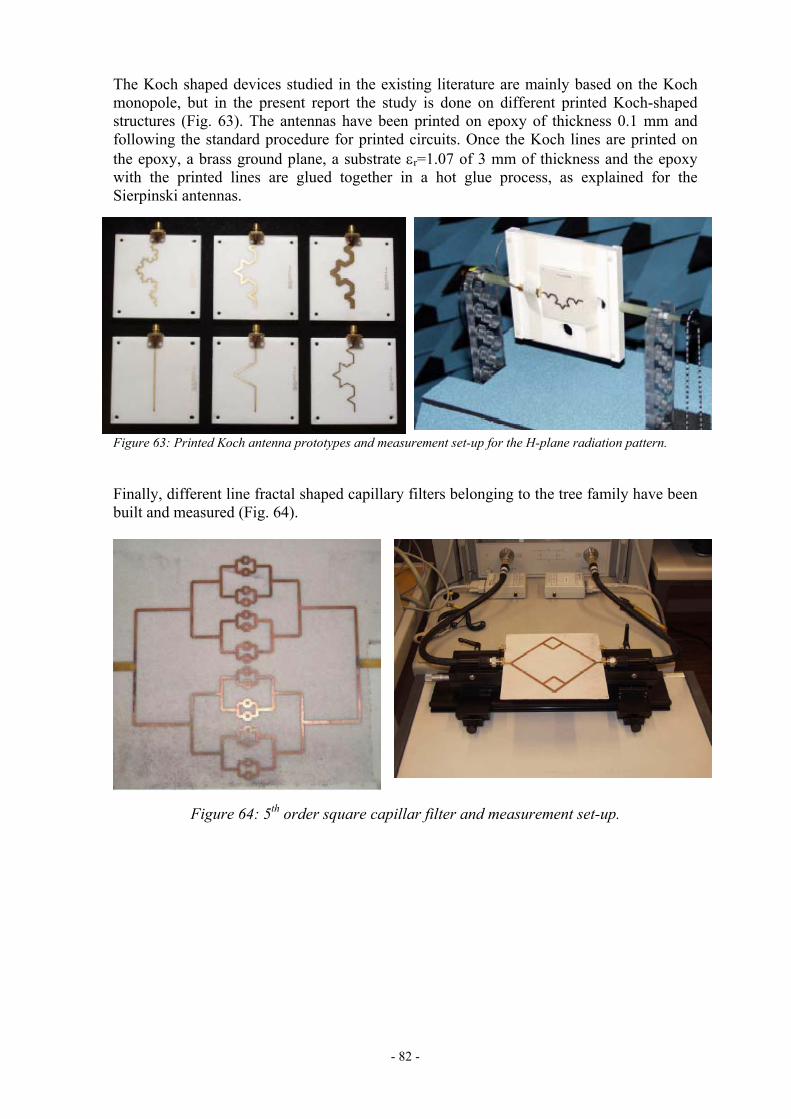
- 82 -
The Koch shaped devices studied in the existing literature are mainly based on the Koch monopole, but in the present report the study is done on different printed Koch-shaped structures (Fig. 63). The antennas have been printed on epoxy of thickness 0.1 mm and following the standard procedure for printed circuits. Once the Koch lines are printed on the epoxy, a brass ground plane, a substrate εr=1.07 of 3 mm of thickness and the epoxy with the printed lines are glued together in a hot glue process, as explained for the Sierpinski antennas.
Figure 63: Printed Koch antenna prototypes and measurement set-up for the H-plane radiation pattern.
Finally, different line fractal shaped capillary filters belonging to the tree family have been built and measured (Fig. 64).
Figure 64: 5th order square capillar filter and measurement set-up.

- 83 -
Task conclusions
Conclusions from this task are:
• The Wheeler cap method is an accurate, fast, and easy to implement technique for the measurement of radiation efficiency and quality factor of electrically small antennas.
• The Directivity/Gain method (in the near-field) can be also used to assess the measured results obtained with the Wheeler method because a measurement facility is accessible and measurement times are reasonable.
• A random positioner allows accurate measurement of antenna efficiency and maximum gain.
• Near field measurements show the field concentration at small parts of the antenna, typical from pre-fractal structures.
• Standard techniques for the fabrication of printed circuit boards are also useful for the manufacture of pre-fractal designs (technique used at UPC).
• Pre-fractal printed antennas can also be constructed by masking the shape on a copper-berilium layer and stacking the ground plane, the substrate, a thin film of glue and the gaskets (technique used at EPFL).
• For a given antenna size and length, non-fractal designs usually have lower measured resonance frequencies and wider bandwidths than pre-fractal monopoles, resulting in lower Q factor and higher efficiencies. Genetically designed pre-fractal antennas attain, in few cases, similar performances than conventional antennas.
• Three-dimensional pre-fractal design does not provide further improvements than planar design in the radiation performance of monopoles. In spite of the smaller electrical sizes attainable thanks to their increased space-filling capability, they have a more intricate topology and larger wires than their planar counterparts. Consequently, efficiency and Q factor for these 3D pre-fractals have unpractical values to real-world applications.

- 84 -
APPENDIX 2- DELIVERABLES TABLE (1ST YEAR)
Project Number: IST-2001-33055
Project Acronym: FRACTALCOMS
Title: Exploring the limits of Fractal Electrodynamics for the future telecommunication technologies
Del. no.
Rev. Title Type1 Classifi-cation2
Due Date Issue Date
D3 1.0 Final task report T2.1: Solution of Electromagnetic simple problems R Pub 31-7-02 17-7-02
D4 1.0 Final task report T2.2: Formulation of EFIE on Fractal Domains R Pub 31-7-02 17-7-02
D13 1.0 Project presentation R Pub 31-7-02 5-6-02
D14 2.0 Dissemination and Use Plan R Pub 31-7-02 20-6-02
D15 Project web site (http://www.tsc.upc.es/fractalcoms) O Pub 31-7-02 3-6-02
D16 1.0 T0+6 intermediate report R Pub 31-7-02 26-7-02
D5 2.0 Final task report T3.1: Advanced Meshing of Fractal Structures R Pub 31-1-03 27-1-03
D6 2.0 Final task report T3.2: Formulation of numerical methods for fractal structures R Pub 31-1-03 27-1-03
D17 2.0 T0+12 annual report R Pub 31-1-03 4-2-03 1 R: Report; D: Demonstrator; S: Software; W: Workshop; O: Other – Specify in footnote 2 Int.: Internal circulation within project (and Commission Project Officer + reviewers if requested) Rest.: Restricted circulation list (specify in footnote) and Commission SO + reviewers only IST: Circulation within IST Programme participants FP5: Circulation within Framework Programme participants Pub.: Public document

- 85 -
APPENDIX 2- DELIVERABLES TABLE (2ND YEAR)
Project Number: IST-2001-33055
Project Acronym: FRACTALCOMS
Title: Exploring the limits of Fractal Electrodynamics for the future telecommunication technologies
Del. no.
Rev. Title Type1 Classifi-cation2
Due Date Issue Date
D1 1.0 Final task report T1.1: Understanding Fractal Electrodynamics Phenomena R Pub 31-7-03 18-7-03
D2 1.0 Final task report T1.2: Fundamental Limits of Fractal Miniature Devices R Pub 31-7-03 18-7-03
D7 Final Final task report T3.3: Simulation of fractal structures: frequency domain R Pub 31-7-02 18-7-03
D8 Final Final task report T3.4: Simulation of fractal structures: frequency domain R Pub 31-7-02 18-7-03
D9 1.0 Final task report T4.1: Design of fractal shaped miniature devices R Pub 31-1-04 5-1-04
D10 1.0 Final task report T4.2: Technological limitations of fractal devices R Pub 31-1-04 5-1-04
D11 1.0 Final task report T4.3: Prototype construction and measurement R Pub 31-1-04 5-1-04
D12 Built prototypes O Pub 31-1-04 23-1-04
D18 1.0 T0+18 intermediary progress report R Pub 31-7-02 18-7-03
D19 1.0 T0+24 final report R Pub 31-1-04 5-1-04 1 R: Report; D: Demonstrator; S: Software; W: Workshop; O: Other – Specify in footnote 2 Int.: Internal circulation within project (and Commission Project Officer + reviewers if requested) Rest.: Restricted circulation list (specify in footnote) and Commission SO + reviewers only IST: Circulation within IST Programme participants FP5: Circulation within Framework Programme participants Pub.: Public document

- 86 -
APPENDIX 3- SUMMARIES OF DELIVERABLES
DELIVERABLE SUMMARY SHEET
Project Number: IST-2001-33055 Project Acronym: FRACTALCOMS Title: Exploring the limits of Fractal Electrodynamics for the future
telecommunication technologies Deliverable N°: D1 Due date: 31-7-03 Delivery Date: 18-7-03 Short Description: Final Report Task 1.1
Understanding Fractal Electrodynamics Phenomena
This deliverable describes the work done in task 1.1 to understand better the
behaviour of electromagnetic fields and electric currents in pre-fractal domains, in order to acquire guidelines for the design of fractal-shaped antennas and microwave devices.
The conclusions are essentially that, as in any kind of antennas, the topology and the antenna geometry determine the radiation parameters. The fractal dimension of the limiting fractal object does not seem to play a significant role.
In order to design good miniature antennas, one have to take into account the electromagnetic coupling between the wire corners, the coupling between the feeder and the wire segments and the existing anti-parallel currents or wire loops.
Some non pre-fractal antennas that closely meet the design criteria, like the two-arm spiral, show excellent miniaturization properties.
It has been found also that high-directivity localized modes are not exclusive of pre-fractal antennas.
Partners owning: UPC, EPFL, UGR Partners contributed: UPC, EPFL, UGR Made available to: Public Domain

- 87 -
DELIVERABLE SUMMARY SHEET
Project Number: IST-2001-33055 Project Acronym: FRACTALCOMS Title: Exploring the limits of Fractal Electrodynamics for the future
telecommunication technologies Deliverable N°: D2 Due date: 31-7-03 Delivery Date: 18-7-03 Short Description: Final Report Task 1.2
Fundamental Limits of Fractal Miniature Devices
The capability of fractal devices for reaching the fundamental limits established for
Euclidean geometries is investigated. The existence of more realistic limits than the restrictive values found in the literature is also explored.
Partners owning: UPC, ROME Partners contributed: UPC, UGR Made available to: Public Domain

- 88 -
DELIVERABLE SUMMARY SHEET
Project Number: IST-2001-33055 Project Acronym: FRACTALCOMS Title: Exploring the limits of Fractal Electrodynamics for the future
telecommunication technologies Deliverable N°: D3 Due date: 31-7-02 Delivery Date: 17-7-02 Short Description: Final Report Task 2.1
Solution of Electromagnetic simple problems
These problems involve the representation of sources radiating in free space and
defined on fractal boundaries, which can be tackled by means of the formal apparatus developed in WP2 Task 2.2. This class of problems encompasses all the direct and inverse problems in antenna theory. The radiation problem of an antenna can be tackled by expressing the vector potential with respect to a current source distribution localized on a fractal support, the estimate of which can be obtained by solving the corresponding electromagnetic integral equation on a fractal support. The main issues are in this case the representation of scalar and vector fields on fractal structures, the setting of the integral equations on fractals and their solutions.
Partners owning: ROME Partners contributed: ROME Made available to: Public Domain
- 89 -
DELIVERABLE SUMMARY SHEET
Project Number: IST-2001-33055 Project Acronym: FRACTALCOMS Title: Exploring the limits of Fractal Electrodynamics for the future
telecommunication technologies Deliverable N°: D4 Due date: 31-7-02 Delivery Date: 17-7-02 Short Description: Final Report Task 2.2
Formulation of EFIE on Fractal Domains The formal mathematical apparatus for setting the integral equations of applied
electromagnetics on fractal curves has been provided. The thin-wire Pocklington EFIE has been formulated on general fractal wire antennas by defining a parametrization of the fractal support through the use of space-filling curves. The numerical solution by method of moments has been thoroughly addressed. This is, to our knowledge, the first theoretical formulation of the EFIE describing wire antennas on a fractal support.
Partners owning: ROME Partners contributed: ROME Made available to: Public Domain
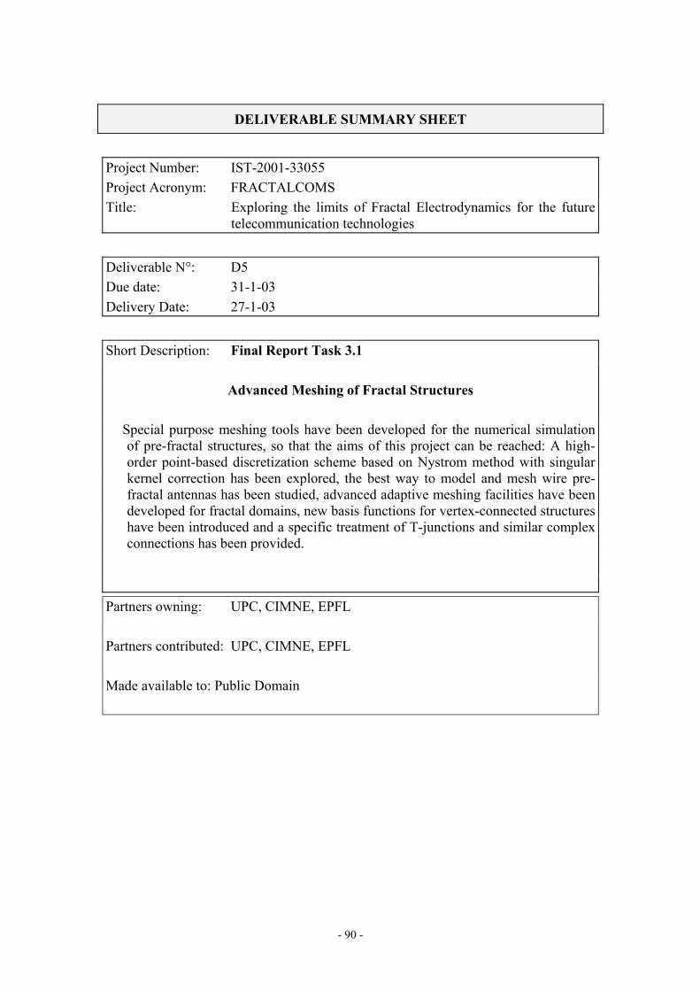
- 90 -
DELIVERABLE SUMMARY SHEET
Project Number: IST-2001-33055 Project Acronym: FRACTALCOMS Title: Exploring the limits of Fractal Electrodynamics for the future
telecommunication technologies Deliverable N°: D5 Due date: 31-1-03 Delivery Date: 27-1-03 Short Description: Final Report Task 3.1
Advanced Meshing of Fractal Structures Special purpose meshing tools have been developed for the numerical simulation
of pre-fractal structures, so that the aims of this project can be reached: A high-order point-based discretization scheme based on Nystrom method with singular kernel correction has been explored, the best way to model and mesh wire pre-fractal antennas has been studied, advanced adaptive meshing facilities have been developed for fractal domains, new basis functions for vertex-connected structures have been introduced and a specific treatment of T-junctions and similar complex connections has been provided.
Partners owning: UPC, CIMNE, EPFL Partners contributed: UPC, CIMNE, EPFL Made available to: Public Domain

- 91 -
DELIVERABLE SUMMARY SHEET
Project Number: IST-2001-33055 Project Acronym: FRACTALCOMS Title: Exploring the limits of Fractal Electrodynamics for the future
telecommunication technologies Deliverable N°: D6 Due date: 31-1-03 Delivery Date: 27-1-03 Short Description: Final Report Task 3.2
Formulation of numerical methods for fractal structures This task is essentially aimed at analyzing critically the problems associated with
the numerical simulations of fractal structures based on the results achieved in Tasks 2.1 and 2.2, and at developing efficient computational approaches for a reliable numerical simulation of high-order iteration prefractal wire antennas using the Electric Field Integral Equation (EFIE).
Partners owning: UPC, EPFL Partners contributed: UPC, EPFL, ROME Made available to: Public Domain
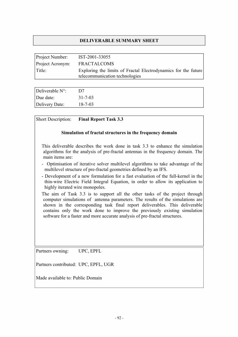
- 92 -
DELIVERABLE SUMMARY SHEET
Project Number: IST-2001-33055 Project Acronym: FRACTALCOMS Title: Exploring the limits of Fractal Electrodynamics for the future
telecommunication technologies Deliverable N°: D7 Due date: 31-7-03 Delivery Date: 18-7-03 Short Description: Final Report Task 3.3
Simulation of fractal structures in the frequency domain This deliverable describes the work done in task 3.3 to enhance the simulation
algorithms for the analysis of pre-fractal antennas in the frequency domain. The main items are:
- Optimisation of iterative solver multilevel algorithms to take advantage of the multilevel structure of pre-fractal geometries defined by an IFS.
- Development of a new formulation for a fast evaluation of the full-kernel in the thin-wire Electric Field Integral Equation, in order to allow its application to highly iterated wire monopoles.
The aim of Task 3.3 is to support all the other tasks of the project through computer simulations of antenna parameters. The results of the simulations are shown in the corresponding task final report deliverables. This deliverable contains only the work done to improve the previously existing simulation software for a faster and more accurate analysis of pre-fractal structures.
Partners owning: UPC, EPFL Partners contributed: UPC, EPFL, UGR Made available to: Public Domain

- 93 -
DELIVERABLE SUMMARY SHEET
Project Number: IST-2001-33055 Project Acronym: FRACTALCOMS Title: Exploring the limits of Fractal Electrodynamics for the future
telecommunication technologies Deliverable N°: D8 Due date: 31-7-03 Delivery Date: 18-7-03 Short Description: Final Report Task 3.4
Simulation of fractal structures in the time domain This deliverable describes the work done in enhancing the simulation algorithms
for the analysis of pre-fractal antennas in the time domain and the results obtained for examples such as the Koch, Hilbert, Sierpinsky and binary tree monopoles and the Koch loop antennas, etc., modelled by thin wires and strips. Because the antennas are assumed to be perfectly electric conductors (PEC) the analysis is carried out using the Method of Moments in the Time Domain (MoMTD).
Partners owning: UGR Partners contributed: UGR Made available to: Public Domain

- 94 -
DELIVERABLE SUMMARY SHEET
Project Number: IST-2001-33055 Project Acronym: FRACTALCOMS Title: Exploring the limits of Fractal Electrodynamics for the future
telecommunication technologies Deliverable N°: D9 Due date: 31-1-04 Delivery Date: 5-1-04 Short Description: Final Report Task 4.1
Design of fractal-shaped miniature devices Several fractal-shaped devices have been designed and simulated. Prototypes have
been also fabricated for some of them. The new pre-fractal-shaped designs include antennas, resonators, filters, and antenna loads. This report gives a brief description of the more interesting ones. Special attention is paid to fractal-shaped resonators and filters fabricated with superconductor materials, since this is a very new and cutting-edge application of pre-fractal structures.
Partners owning: UPC, EPFL Partners contributed: UPC, EPFL, UGR Made available to: Public Domain

- 95 -
DELIVERABLE SUMMARY SHEET
Project Number: IST-2001-33055 Project Acronym: FRACTALCOMS Title: Exploring the limits of Fractal Electrodynamics for the future
telecommunication technologies Deliverable N°: D10 Due date: 31-1-04 Delivery Date: 5-1-04 Short Description: Final Report Task 4.2
Technological limitations of fractal-shaped devices Practical limitations on the fabrication of fractal devices are considered. Examples
of these limitations are shown for the most common geometries.
Partners owning: UPC, EPFL Partners contributed: UPC, EPFL Made available to: Public Domain

- 96 -
DELIVERABLE SUMMARY SHEET
Project Number: IST-2001-33055 Project Acronym: FRACTALCOMS Title: Exploring the limits of Fractal Electrodynamics for the future
telecommunication technologies Deliverable N°: D11 Due date: 31-1-04 Delivery Date: 5-1-04 Short Description: Final Report Task 4.3
Prototype construction and measurement A summary of the measuring techniques used to characterize pre-fractal devices is
presented in this report. The fabrication and characterization of some prototypes used to assess the measuring technique is also presented.
Partners owning: UPC, EPFL Partners contributed: UPC, EPFL Made available to: Public Domain

- 97 -
DELIVERABLE SUMMARY SHEET
Project Number: IST-2001-33055 Project Acronym: FRACTALCOMS Title: Exploring the limits of Fractal Electrodynamics for the future
telecommunication technologies Deliverable N°: D12 Due date: 31-1-04 Delivery Date: 23-1-04 Short Description: Built prototypes The built prototypes will be delivered to the project officer at the final review
meeting, Brussels 23-1-04.
Partners owning: UPC, EPFL Partners contributed: UPC, EPFL Made available to: Public Domain

- 98 -
DELIVERABLE SUMMARY SHEET
Project Number: IST-2001-33055 Project Acronym: FRACTALCOMS Title: Exploring the limits of Fractal Electrodynamics for the future
telecommunication technologies Deliverable N°: D13 Due date: 31-7-02 Delivery Date: 5-6-02 Short Description: Project Presentation
Partners owning: UPC Partners contributed: UPC Made available to: Public Domain

- 99 -
DELIVERABLE SUMMARY SHEET
Project Number: IST-2001-33055 Project Acronym: FRACTALCOMS Title: Exploring the limits of Fractal Electrodynamics for the future
telecommunication technologies Deliverable N°: D14 Due date: 31-7-02 Delivery Date: 20-6-02 Short Description: Dissemination and Use Plan
Partners owning: UPC Partners contributed: UPC Made available to: Public Domain

- 100 -
DELIVERABLE SUMMARY SHEET
Project Number: IST-2001-33055 Project Acronym: FRACTALCOMS Title: Exploring the limits of Fractal Electrodynamics for the future
telecommunication technologies Deliverable N°: D15 Due date: 31-7-02 Delivery Date: 3-6-02 Short Description: Project web site
http://www.tsc.upc.es/fractalcoms/
Partners owning: UPC Partners contributed: UPC Made available to: Public Domain

- 101 -
DELIVERABLE SUMMARY SHEET
Project Number: IST-2001-33055 Project Acronym: FRACTALCOMS Title: Exploring the limits of Fractal Electrodynamics for the future
telecommunication technologies Deliverable N°: D16 Due date: 31-7-02 Delivery Date: 26-7-02 Short Description: T0+6 Intermediate Progress Report
Partners owning: UPC, ROME, EPFL, UGR, CIMNE Partners contributed: UPC, ROME, EPFL, UGR, CIMNE Made available to: Public Domain

- 102 -
DELIVERABLE SUMMARY SHEET
Project Number: IST-2001-33055 Project Acronym: FRACTALCOMS Title: Exploring the limits of Fractal Electrodynamics for the future
telecommunication technologies Deliverable N°: D17 Due date: 31-1-03 Delivery Date: 27-1-03 Short Description: T0+12 Annual Progress Report
Partners owning: UPC, ROME, EPFL, UGR, CIMNE Partners contributed: UPC, ROME, EPFL, UGR, CIMNE Made available to: Public Domain

- 103 -
DELIVERABLE SUMMARY SHEET
Project Number: IST-2001-33055 Project Acronym: FRACTALCOMS Title: Exploring the limits of Fractal Electrodynamics for the future
telecommunication technologies Deliverable N°: D18 Due date: 31-7-03 Delivery Date: 18-7-03 Short Description: T0+18 Intermediate Progress Report
Partners owning: UPC, ROME, EPFL, UGR, CIMNE Partners contributed: UPC, ROME, EPFL, UGR, CIMNE Made available to: Public Domain
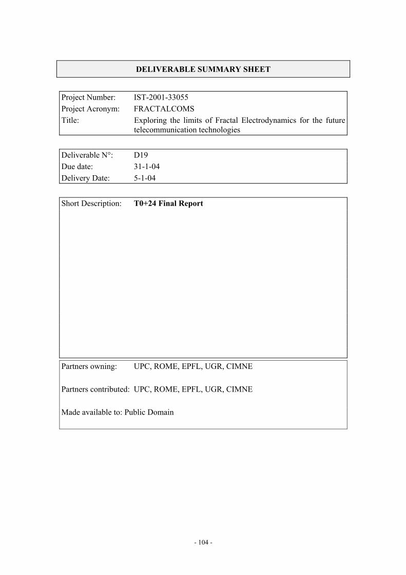
- 104 -
DELIVERABLE SUMMARY SHEET
Project Number: IST-2001-33055 Project Acronym: FRACTALCOMS Title: Exploring the limits of Fractal Electrodynamics for the future
telecommunication technologies Deliverable N°: D19 Due date: 31-1-04 Delivery Date: 5-1-04 Short Description: T0+24 Final Report
Partners owning: UPC, ROME, EPFL, UGR, CIMNE Partners contributed: UPC, ROME, EPFL, UGR, CIMNE Made available to: Public Domain

- 105 -
APPENDIX 4 (A)- COMPARATIVE INFORMATION ON RESOURCES (PERSON MONTHS) – 1ST YEAR
Effort in person months for reporting period 1/12/2001 -30/11/2002
UPC ROME EPFL UGR CIMNE Total
Period Total Period Total Period Total Period Total Period Total Period Total
WP/Task Est. Act. Est. Act. Est. Act. Est. Act. Est. Act. Est. Act. Est. Act. Est. Act. Est. Act. Est. Act. Est. Act. Est. Act.
WP0 1 1 1 1 1 1 1 1
WP1
Task 1.1 4 4.12 4 4.12 4 4 4 4 8 8.12 8 8.12
Task 1.2
WP 2
Task 2.1 8 8.2 8 8.2 8 8.2 8 8.2
Task 2.2 10 10.1 10 10.1 10 10.1 10 10.1
WP 3
Task 3.1 3 3.15 3 3.15 3 3 3 3 13 16 13 16 19 22.15 19 22.15
Task 3.2 5 5.1 5 5.1 0 3 0 3 10 10 10 10 15 18.1 15 18.1
Task 3.3 3.1 3.15 3.1 3.15 3 2 3 2 6.1 5.15 6.1 5.15
Task 3.4 18 10.67 18 10.67 18 10.67 18 10.67
WP 4
Task 4.1
Task 4.2
Task 4.3 1 1.1 1 1.1 1 1.1 1 1.1
Total 17.1 17.62 17.1 17.62 18 21.3 18 21.3 20 19 20 19 18 10.67 18 10.67 13 16 13 16 86.1 84.59 86.1 84.59
Period: Est.: estimated effort in contract for period Act.: effort actually spent in period Total: Est.: estimated cumulative effort to date in contract Act.: cumulative effort to date actually spent

- 106 -
APPENDIX 4 (A)- COMPARATIVE INFORMATION ON RESOURCES (PERSON MONTHS) – 2ND YEAR
Effort in person months for reporting period 1/12/2002 -30/11/2003
UPC ROME EPFL UGR CIMNE Total
Period Total Period Total Period Total Period Total Period Total Period Total
WP/Task Est. Act. Est. Act. Est. Act. Est. Act. Est. Act. Est. Act. Est. Act. Est. Act. Est. Act. Est. Act. Est. Act. Est. Act.
WP0 1 1 2 2 1 1 2 2
WP1
Task 1.1 2 2.9 6 7.02 5 11.1 5 11.1 4 4 0 3 0 3 7 17 15 25.12
Task 1.2 5 5.2 5 5.2 3 3.3 3 3.3 0 3 0 3 8 11.5 8 11.5
WP 2
Task 2.1 8 8.2 8 8.2
Task 2.2 10 10.1 10 10.1
WP 3
Task 3.1 3 3.15 3 3 7 5.3 20 21.3 7 5.3 26 27.45
Task 3.2 5 5.1 10 10 15 15.1
Task 3.3 1.9 2.4 5 5.55 2 3 5 5 3.9 5.4 10 10.55
Task 3.4 18 19.75 36 30.42 18 19.75 36 30.42
WP 4
Task 4.1 3 4.3 3 4.3 4 4 4 4 0 5.45 0 5.45 7 13.75 7 13.75
Task 4.2 5 5.4 5 5.4 6 6 6 6 11 11.4 11 11.4
Task 4.3 5 5.4 6 6.5 8 8 8 8 13 13.4 14 14.5
Total 22.9 26.6 40 44.22 8 14.4 26 32.7 20 21 40 40 18 31.2 36 41.87 7 5.3 20 21.3 75.9 98.5 162 180.09
Period: Est.: estimated effort in contract for period Act.: effort actually spent in period Total: Est.: estimated cumulative effort to date in contract Act.: cumulative effort to date actually spent

- 107 -
APPENDIX 4 (B) - COMPARATIVE INFORMATION ON RESOURCES (COSTS) – 1ST YEAR
Costs in euro for reporting period 1/12/2001-30/11/2002 All costs in kEURO rounded to the first decimal place.
Period: Est.: estimated costs in contract for period Act.: actual costs in period
Total: Est.: estimated cumulative costs to date in contract Act.: cumulative actual costs to date
Cost category Est. Act. Est. Act. Est. Act. Est. Act. Est. Act. Est. Act. Est. Act. Est. Act. Est. Act. Est. Act. Est. Act. Est. Act.Direct costs
1. Personnel 54.7 56.6 54.7 56.6 50 75.6 50 75.6 76 72 76 72 22 14 22 14 52 60.2 52 60.2 254.7 278.4 254.7 278.42. Durable equipment 8 8 8 8 8 8 8 83. Subcontracting 0 0 0 04. Travel and subsistence 9 9.3 9 9.3 9 7.4 9 7.4 6.5 6.7 6.5 6.7 5 5.8 5 5.8 3.6 2 3.6 2 33.1 31.2 33.1 31.2
5. Consumables 1 0.9 1 0.9 1 1.1 1 1.1 4 4 4 4 4.2 4.2 10.2 6 10.2 66. Computing 0 0 0 07. Protection of knowledge
0 0 0 0
8. Other specific costs 4 1 4 1 4 1 4 1Subtotal 0 0 0 0
Indirect costs 0 0 0 09. Overheads 43.8 45.3 43.8 45.3 40 60.5 40 60.5 9.5 9 9.5 9 6.3 4 6.3 4 41.6 48.2 41.6 48.2 141.2 167 141.2 167
Total 113 113 113 113 100 145 100 145 104 100 104 100 38 24 38 24 97 110 97 110 451 492 451 492
Total
Total
Period Total
CIMNE
PeriodPeriod Total Period Total Period Total Period Total
UPC ROME EPFL UGR

- 108 -
APPENDIX 4 (B) - COMPARATIVE INFORMATION ON RESOURCES (COSTS) – 2ND YEAR
Costs in euro for reporting period 1/12/2002-30/11/2003 All costs in kEURO rounded to the first decimal place.
Period: Est.: estimated costs in contract for period Act.: actual costs in period
Total: Est.: estimated cumulative costs to date in contract Act.: cumulative actual costs to date
Cost category Est. Act. Est. Act. Est. Act. Est. Act. Est. Act. Est. Act. Est. Act. Est. Act. Est. Act. Est. Act. Est. Act. Est. Act.Direct costs
1. Personnel 73 80.4 127.7 137 50 50,2 100 125.8 76.1 80.1 152.1 152.1 22.1 29.2 44.1 43.2 28 25 80 85.2 249.2 214.7 503.9 543.32. Durable equipment 0 0 0 03. Subcontracting 0 0 0 04. Travel and subsistence 9 3.3 18 12.6 9 4 18 11.4 6.5 6.5 13 13.2 5 7.3 10 13.1 2.4 1.8 6 3.8 31.9 22.9 65 54.1
5. Consumables 1 0 2 0.9 1 0.9 2 2.0 4 4 8 8 4.2 6.1 8.4 6.1 10.2 11 20.4 176. Computing 0 0 0 07. Protection of knowledge
0 0 0 0
8. Other specific costs 4 0 8 1 4 0 8 1Subtotal 0 0 0 0
Indirect costs 0 0 0 09. Overheads 58.4 64.3 102.2 110 40 40,1 80 100.7 8.7 9.2 18.1 18.2 6.3 8.5 12.5 12.5 22.4 20 64 68.2 135.8 102 276.8 309.2
Total 145.4 148 257.9 261 100 4.9 200 239.9 95.3 99.8 191.2 191.5 37.6 51.1 75 74.9 52.8 46.8 150 157.2 431.1 350.6 874.1 924.6
Total
Total
Period Total
CIMNE
PeriodPeriod Total Period Total Period Total Period Total
UPC ROME EPFL UGR
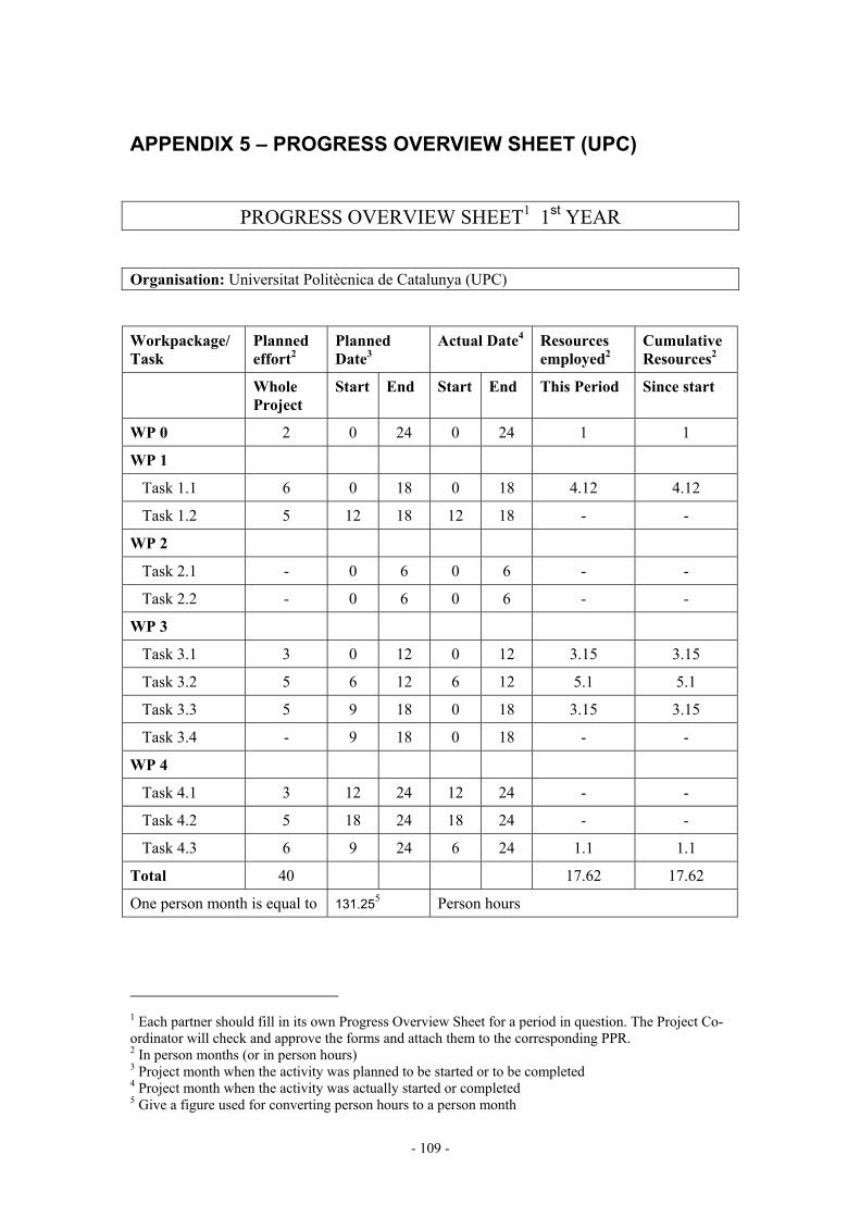
- 109 -
APPENDIX 5 – PROGRESS OVERVIEW SHEET (UPC)
PROGRESS OVERVIEW SHEET1 1st YEAR
Organisation: Universitat Politècnica de Catalunya (UPC)
Workpackage/Task
Planned effort2
Planned Date3
Actual Date4 Resources employed2
Cumulative Resources2
Whole Project
Start End Start End This Period Since start
WP 0 2 0 24 0 24 1 1
WP 1
Task 1.1 6 0 18 0 18 4.12 4.12
Task 1.2 5 12 18 12 18 - -
WP 2
Task 2.1 - 0 6 0 6 - -
Task 2.2 - 0 6 0 6 - -
WP 3
Task 3.1 3 0 12 0 12 3.15 3.15
Task 3.2 5 6 12 6 12 5.1 5.1
Task 3.3 5 9 18 0 18 3.15 3.15
Task 3.4 - 9 18 0 18 - -
WP 4
Task 4.1 3 12 24 12 24 - -
Task 4.2 5 18 24 18 24 - -
Task 4.3 6 9 24 6 24 1.1 1.1
Total 40 17.62 17.62
One person month is equal to 131.255 Person hours
1 Each partner should fill in its own Progress Overview Sheet for a period in question. The Project Co-ordinator will check and approve the forms and attach them to the corresponding PPR. 2 In person months (or in person hours) 3 Project month when the activity was planned to be started or to be completed 4 Project month when the activity was actually started or completed 5 Give a figure used for converting person hours to a person month

- 110 -
Main contribution during this period
Workpackage/Task Action
WP 1
Task 1.1
• It has been found that topology has more influence than fractal dimension in the radiation parameters of self-resonant pre-fractal wire monopoles.
• The behaviour of the antenna resonant frequency as a function of wire length has been explained by a coupling –or shortcut- effect hypothesis.
• As a result, some guidelines for the design of small antennas have been derived.
WP 3
Task 3.1
• It has been found than Nystrom method is not suitable for discretizing the Electric Field Integral Equation (EFIE) on open surfaces like antennas.
• It has been found that the most adequate subdomain approach for meshing highly iterated pre-fractal wires is a extrusion strip triangle mesh. Good convergence with mesh size or numerical integration refinement is achieved.
Task 3.2
• The accuracy of the commonly used approximations for the analysis of thin-wire antennas when applied to fractal structures has been evaluated. It has been shown that, when the EFIE is discretized in subdomain basis functions, the thin-wire kernel can be used without introducing significant errors only in low-iteration pre-fractals.
• In order to solve very large wire antenna problems, the EFIE for wires has been implemented in FIESTA. Thee different formulations of the kernel have been programmed: thin-wire, thin-wire with equivalent radius and full kernel.
Task 3.3
• In order to accelerate the simulation of multilevel pre-fractal antennas, a GMRES+MLMDA technique has been developed jointly by UPC and EPFL. Reduction factors of 20 in the total computation time and 10 in the total memory have been achieved.
WP 4
Task 4.3
• UPC has arranged a measurement facility for small antennas based on the Wheeler cap method. Many prototypes have been constructed and measured in order to test the set-up and to support task 1.1.

- 111 -
Deliverables due this period
Deliverable number
Title of Deliverable Status (Draft Final, Pending)
D13 D14 D15 D16 D5 D6 D17
Project presentation Dissemination and Use Plan Project web site (http://www.tsc.upc.es/fractalcoms) T0+6 intermediate report Final task report T3.1: Advanced Meshing of Fractal
Structures Final task report T3.2: Formulation of numerical
methods for fractal structures T0+12 annual report
Final Final Final Final Final Final Final
Dissemination actions (articles, workshops, conferences etc.)
FRACTALCOMS website is active since T0+6 and the address has communicated to the Fractal Antennas® European company FRACTUS S.A.
4 international conference papers
1st Conference on Advances and Applications of GiD 2002 IEEE AP-S International Symposium: (2 papers) Journées Internationales de Nice sur les Antennes JINA-2002
2 international journal papers
IEE Electronics Letters: (1 paper published, 1 rejected)

- 112 -
Deviations from the planned work schedule/reasons/corrective actions/special attention required
It was decided in the kick-off meeting that task
T3.3: Simulation of fractal structures in the frequency domain would start at T0 although they were originally scheduled to start at T0+9. It was decided at the T0+6 meeting that task
T4.3: Prototype construction and measurement would start at T0+6 although it was originally scheduled to start at T0+9.
Planned actions for the next period
Start tasks:
T1.2: Fundamental limits of fractal miniature devices T4.1: Design of fractal-shaped miniature devices T4.2: Technological limitations of fractal devices
Continue working in the active tasks: T1.1: Understanding fractal electrodynamics phenomena T3.3: Simulation of fractal structures, frequency domain T4.3: Prototype construction and measurement

- 113 -
PROGRESS OVERVIEW SHEET6 2nd YEAR
Organisation: Universitat Politècnica de Catalunya (UPC)
Workpackage/Task
Planned effort7
Planned Date8
Actual Date9 Resources employed2
Cumulative Resources2
Whole Project
Start End Start End This Period Since start
WP 0 2 0 24 0 24 1 1
WP 1
Task 1.1 6 0 18 0 18 2.9 7.02
Task 1.2 5 12 18 12 18 5.2 5.2
WP 2
Task 2.1 - 0 6 0 6 - -
Task 2.2 - 0 6 0 6 - -
WP 3
Task 3.1 3 0 12 0 12 - 3.15
Task 3.2 5 6 12 6 12 - 5.1
Task 3.3 5 9 18 0 18 2.4 5.55
Task 3.4 - 9 18 0 18 - -
WP 4
Task 4.1 3 12 24 12 24 4.3 4.3
Task 4.2 5 18 24 18 24 5.4 5.4
Task 4.3 6 9 24 6 24 5.4 6.5
Total 40 26.6 44.22
One person month is equal to 131.2510 Person hours
6 Each partner should fill in its own Progress Overview Sheet for a period in question. The Project Co-ordinator will check and approve the forms and attach them to the corresponding PPR. 7 In person months (or in person hours) 8 Project month when the activity was planned to be started or to be completed 9 Project month when the activity was actually started or completed 10 Give a figure used for converting person hours to a person month

- 114 -
Main contribution during this period
Workpackage/Task Action
WP 1
Task 1.1
• New experiments have confirmed the conclusions reached during the first year.
• 3-D pre-fractal structures can pack more wire into the same volume. Smaller electrical size is achieved, but efficiency and Q factor for these 3D pre-fractals have unpractical values to real-world applications.
Task 1.2 • The practical limit of bandwidth and loss efficiency for small antennas has been found experimentally. The results agree very well with the theoretical formula recently published by Thiele et al.
WP 3
Task 3.3
• A new formulation of the thin-wire EFIE full-kernel has been developed in order to analyze highly-iterated pre-fractal wires discretized into very short wire segments, in a reasonable run time.
WP 4
Task 4.1 • Many pre-fractal devices have been designed and tested. The most significant results have been obtained with miniature resonator and filters based in the Hilber pre-fractal and made of superconductive materials.
Task 4.2 • The technological limitations for manufacturing pre-fractal wires or strips with non-zero width have been established. Formulas that give the maximum iteration achievable for the Koch, Hilbert and Sierpinski pre-fractals have been found.
Task 4.3
• Many prototypes have been constructed and measured in order to support tasks 1.1, 1.2, 4.1 and 4.2.
Deliverables due this period
Deliverable number
Title of Deliverable Status (Draft Final, Pending)
D1 D2 D7 D9 D10 D11 D12 D18 D19
Final task report T1.1 Final task report T1.2 Final task report T3.3 Final task report T4.1 Final task report T4.2 Final task report T4.3 Built prototypes
T0+18 intermediate progress report T0+24 Final report
Final Final Final Final Final Final Delivered at final review Final Final

- 115 -
Dissemination actions (articles, workshops, conferences etc.)
FRACTALCOMS website is active since T0+6 and the address has communicated to the Fractal Antennas® European company FRACTUS S.A. The website has been enhanced during the second year of the project.
13 international conference papers
2003 IEEE AP-S International Symposium: (6 papers) III Encuentro Ibérico de electromagnetismo computacional. 1st International Conference on Electromagnetic Near Field Characterization. 2004 URSI Commission B International Symposium on Electromagnetic… (2 papers) 2nd ESA Antenna Technology Workshop… (2 papers) International Microwave Symposium 2004
12 international journal papers
IEEE Trans. on Antennas and Propag: (4 papers published or accepted + 2 in review) IEE Electronics Letters: (1 paper published, 1 in review) GiD Times (1 paper published) Microwave and Optical Technology Letters (1 paper published) Antennas and Wireless Propagation Letters, IEEE (2 papers published)
12 national journal papers
BURAN (accepted)
Deviations from the planned work schedule/reasons/corrective actions/special attention required
None.
Planned actions for the next period

- 116 -
APPENDIX 5 – PROGRESS OVERVIEW SHEET (ROME)
PROGRESS OVERVIEW SHEET11 1st year
Organisation: “La Sapienza” Università degli studi di Roma (ROME)
Workpackage/Task
Planned effort12
Planned Date13
Actual Date14
Resources employed2
Cumulative Resources2
Whole Project
Start End Start End This Period Since start
WP 0 - 0 24 0 24 - -
WP 1
Task 1.1 5 0 18 0 18 0 0
Task 1.2 3 12 18 12 18 - -
WP 2
Task 2.1 8 0 6 0 6 8.2 8.2
Task 2.2 10 0 6 0 6 10.1 10.1
WP 3
Task 3.1 - 0 12 0 12 - -
Task 3.2 0 6 12 6 12 3 3
Task 3.3 - 9 18 0 18 - -
Task 3.4 - 9 18 0 18 - -
WP 4 - -
Task 4.1 - 12 24 12 24 - -
Task 4.2 - 18 24 18 24 - -
Task 4.3 - 9 24 6 24 - -
Total 26 21.3 21.3
One person month is equal to 131.2515 Person hours
11 Each partner should fill in its own Progress Overview Sheet for a period in question. The Project Co-ordinator will check and approve the forms and attach them to the corresponding PPR. 12 In person months (or in person hours) 13 Project month when the activity was planned to be started or to be completed 14 Project month when the activity was actually started or completed 15 Give a figure used for converting person hours to a person month
- 117 -
Main contribution during this period
Wp/Task Action
WP 2
Task 2.1
• It has been observed in electrostatic problems that, as the number of IFS iterations increases, the charge density –solution of the inverse problem- becomes a multifractal measure in the limit. Conversely, the charge measure –integral of charge density along the fractal curve- converges towards an invariant shape as the number of iterations increases.
• The highly singular structure of the charge measure prevents the use of collocation approaches for numerical discretization, since they make use of localized functions.
Task 2.2
• The formal mathematical apparatus for setting the integral equations of applied electromagnetics on fractal curves has been provided. The thin-wire Pocklington EFIE has been formulated on general fractal wire antennas by defining a parametrization of the fractal support through the use of space-filling curves. The numerical solution by method of moments has been thoroughly addressed. This is, to our knowledge, the first theoretical formulation of the EFIE describing wire antennas on a fractal support.
• It has been shown that when the IFS iteration number increases beyond a certain threshold, the change in radiation patterns and input impedance of the antenna tend to zero. In other words, there is no use in increasing the number of IFS iterations.
WP 3
Task 3.2
• Some numerical approaches based on the Galërkin-Petrov expansion for solving the EFIE in pre-fractal structures have been studied. The entire-domain Galërkin approach proposed furnishes reliable and convergent approximations for the computation of the current and the radiation parameters of thin-wire antennas.

- 118 -
Deliverables due this period
Deliverable number
Title of Deliverable Status (Draft Final, Pending)
D3 D4
Final task report T2.1: Solution of Electromagnetic simple problems
Final task report T2.2: Formulation of EFIE on Fractal Domains
Final Final
Dissemination actions (articles, workshops, conferences etc.)
2 international conference papers:
XXVIIth URSI General Assembly Journées Internationales de Nice sur les Antennes JINA-2002
2 Italian conference papers
Quattordicesima RIunione Nazionale di Elettromagnetismo, (2 papers) 1 Journal paper
Optics Letters, (1 paper accepted)
Deviations from the planned work schedule/reasons/corrective actions/special attention required
ROME partner has dedicated 3 man-months to task 3.2 “Formulation of numerical methods for fractal structures”, although this was not scheduled in the project proposal. For that reason, the work of ROME partner in task 1.1 “Understanding fractal electrodynamics phenomena” has been delayed to the 2nd year.
Planned actions for the next period
Start tasks:
T1.2: Fundamental limits of fractal miniature devices
Start working in the active tasks: T1.1: Understanding fractal electrodynamics phenomena

- 119 -
PROGRESS OVERVIEW SHEET16 2nd year
Organisation: “La Sapienza” Università degli studi di Roma (ROME)
Workpackage/Task
Planned effort17
Planned Date18
Actual Date19
Resources employed2
Cumulative Resources2
Whole Project
Start End Start End This Period Since start
WP 0 - 0 24 0 24 - -
WP 1
Task 1.1 5 0 18 0 18 11.1 11.1
Task 1.2 3 12 18 12 18 3.3 3.3
WP 2
Task 2.1 8 0 6 0 6 - 8.2
Task 2.2 10 0 6 0 6 - 10.1
WP 3
Task 3.1 - 0 12 0 12 - -
Task 3.2 0 6 12 6 12 3 3
Task 3.3 - 9 18 0 18 - -
Task 3.4 - 9 18 0 18 - -
WP 4 - -
Task 4.1 - 12 24 12 24 - -
Task 4.2 - 18 24 18 24 - -
Task 4.3 - 9 24 6 24 - -
Total 26 14.4 32.7
One person month is equal to 131.2520 Person hours
16 Each partner should fill in its own Progress Overview Sheet for a period in question. The Project Co-ordinator will check and approve the forms and attach them to the corresponding PPR. 17 In person months (or in person hours) 18 Project month when the activity was planned to be started or to be completed 19 Project month when the activity was actually started or completed 20 Give a figure used for converting person hours to a person month

- 120 -
Main contribution during this period
Wp/Task Action
WP 1
Task 1.1
• Renormalization methods and simplicial complex analysis are not particularly significant in solving radiation problems involving fractal antennas (which are essentially based on the enforcement of boundary conditions) but fit naturally the theoretical setting based on trasmission-line theory involving fractal structures and spectral analysis of fractal resonators.
• The theoretical and numerical theory developed in WP2.2 for EFIE on wire antennas has been extended to consider the case of exact kernels.
• A new family of smooth class of wavelet systems on the unit interval has been proposed and applied to wire-fractal antennas.
• Approximate (effective) kernels leading to well-posed matrix formulation of EFIE based on Galerkin expansion has been proposed.
Task 1.2
• Theoretical analysis indicates that the fractal nature of the antenna support cannot lead to a modification of the fundamental limit for small radiating structures.
Deliverables due this period
Deliverable number
Title of Deliverable Status (Draft Final, Pending)
D1 D2
Final task report T1.1 Final task report T1.2
Final Final
Dissemination actions (articles, workshops, conferences etc.)
2 international conference papers:
Workshop on ‘Electromagnetics in a complex word: challenges and perspectives’ 2nd ESA Antenna Technology Workshop…
2 Journal paper
Chaos, solitons and fractals (2 papers to be submitted on January 10, 2003)
Deviations from the planned work schedule/reasons/corrective actions/special attention required
None.
Planned actions for the next period

- 121 -
APPENDIX 5 – PROGRESS OVERVIEW SHEET (EPFL)
PROGRESS OVERVIEW SHEET21 1st YEAR
Organisation: École Polytechnique Fédérale de Lausanne (EPFL)
Workpackage/Task
Planned effort22
Planned Date23
Actual Date24
Resources employed2
Cumulative Resources2
Whole Project
Start End Start End This Period Since start
WP 0 - 0 24 0 24 - -
WP 1
Task 1.1 4 0 18 0 18 4 4
Task 1.2 - 12 18 12 18 - -
WP 2
Task 2.1 - 0 6 0 6 - -
Task 2.2 - 0 6 0 6 - -
WP 3
Task 3.1 3 0 12 0 12 3 3
Task 3.2 10 6 12 6 12 10 10
Task 3.3 5 9 18 0 18 2 2
Task 3.4 - 9 18 0 18 - -
WP 4
Task 4.1 4 12 24 12 24 - -
Task 4.2 6 18 24 18 24 - -
Task 4.3 8 9 24 6 24 - -
Total 40 19 19
One person month is equal to 131.2525 Person hours
21 Each partner should fill in its own Progress Overview Sheet for a period in question. The Project Co-ordinator will check and approve the forms and attach them to the corresponding PPR. 22 In person months (or in person hours) 23 Project month when the activity was planned to be started or to be completed 24 Project month when the activity was actually started or completed 25 Give a figure used for converting person hours to a person month

- 122 -
Main contribution during this period
WP/Task Action
WP 1
Task 1.1
• It has been found that the meander printed line has localized modes (fractons), that were formerly considered exclusive of pre-fractal structures.
• An antenna that agrees with the design guidelines resulting from task 1.1 (the two-arm spiral) has been studied. The resonant frequency scales almost inversely proportional to the wire length, which assesses the goodness of the task 1.1 design guidelines.
WP 3
Task 3.1
• EPFL has developed a new set of quadrangular basis functions that simplify enormously the electric connection between different patches of the pre-fractal and can solve many connectivity problems.
• A study of currents and charges in a T-junction has been done in order to set up the basic strategy for the modeling of connections and junctions in pre-fractal antennas.
Task 3.2
• This task has become the natural follow-up of task 3.1 following the successful developments of quadrangular basis functions which will provide also an efficient EFIE discrete formulation. Numerical integration routines have been adapted to these basis.
Task 3.3
• EPFL has cooperated with UPC in optimising numerical methods for pre-fractal multilevel structures.
• EPFL frequency-domain electromagnetic solver has been used to support other tasks.
WP 4
Task 4.3
• EPFL has his unique small-antennas measurement set-up ready for FRACTALCOMS project. The development of this facility has been considered as essential and some resources from Task 3.2 have been redirected to this task

- 123 -
Deliverables due this period
Deliverable number
Title of Deliverable Status (Draft Final, Pending)
D5 D6
Final task report T3.1 Final task report T3.2
Final Final
Dissemination actions (articles, workshops, conferences etc.)
2 international conference papers
2002 IEEE AP-S International Symposium Journées Internationales de Nice sur les Antennes JINA-2002
Deviations from the planned work schedule/reasons/corrective actions/special attention required
It was decided in the kick-off meeting that task
T3.3: Simulation of fractal structures in the frequency domain would start at T0 although they were originally scheduled to start at T0+9. It was decided at the T0+6 meeting that task
T4.3: Prototype construction and measurement would start at T0+6 although it was originally scheduled to start at T0+9.
Planned actions for the next period
Start tasks:
T4.1: Design of fractal-shaped miniature devices T4.2: Technological limitations of fractal devices
Continue working in the active tasks: T1.1: Understanding fractal electrodynamics phenomena T3.3: Simulation of fractal structures, frequency domain T4.3: Prototype construction and measurement

- 124 -
PROGRESS OVERVIEW SHEET26 2nd YEAR
Organisation: École Polytechnique Fédérale de Lausanne (EPFL)
Workpackage/Task
Planned effort27
Planned Date28
Actual Date29
Resources employed2
Cumulative Resources2
Whole Project
Start End Start End This Period Since start
WP 0 - 0 24 0 24 - -
WP 1
Task 1.1 4 0 18 0 18 - 4
Task 1.2 - 12 18 12 18 - -
WP 2
Task 2.1 - 0 6 0 6 - -
Task 2.2 - 0 6 0 6 - -
WP 3
Task 3.1 3 0 12 0 12 - 3
Task 3.2 10 6 12 6 12 - 10
Task 3.3 5 9 18 0 18 3 5
Task 3.4 - 9 18 0 18 - -
WP 4
Task 4.1 4 12 24 12 24 4 4
Task 4.2 6 18 24 18 24 6 6
Task 4.3 8 9 24 6 24 8 8
Total 40 21 40
One person month is equal to 131.2530 Person hours
26 Each partner should fill in its own Progress Overview Sheet for a period in question. The Project Co-ordinator will check and approve the forms and attach them to the corresponding PPR. 27 In person months (or in person hours) 28 Project month when the activity was planned to be started or to be completed 29 Project month when the activity was actually started or completed 30 Give a figure used for converting person hours to a person month

- 125 -
Main contribution during this period
WP/Task Action
WP 3
Task 3.3
• The frequency domain simulation methods available at EPFL have been used to analyse many pre-fractal structures in order to support task 4.1 and 4.2.
WP 4
Task 4.1
• A H-tree pre-fractal structure has been designed and thoroughly studied.
• Innovative pre-fractal capillary filters have been designed, numerically analysed and measured.
Task 4.2
• The technological limitations for manufacturing pre-fractal wires or strips with non-zero width have been established.
Task 4.3
• Many prototypes have been constructed and measured in order to support tasks 4.1 and 4.2.
Deliverables due this period
Deliverable number
Title of Deliverable Status (Draft Final, Pending)
D1 D7 D9 D10 D11 D12
Final task report T1.1 Final task report T3.3 Final task report T4.1 Final task report T4.2 Final task report T4.3 Built prototypes
Final Final Final Final Final Delivered at the review meeting
Dissemination actions (articles, workshops, conferences etc.)
2 international conference papers
III Encuentro Ibérico de electromagnetismo computacional. 2nd ESA Antenna Technology Workshop….
1 international journal paper
IEEE Trans. on Antennas and Propagation (published)
Deviations from the planned work schedule/reasons/corrective actions/special attention required
None.
Planned actions for the next period

- 126 -
APPENDIX 5 – PROGRESS OVERVIEW SHEET (UGR)
PROGRESS OVERVIEW SHEET31 1st YEAR
Organisation: Universidad de Granada (UGR)
Workpackage/Task
Planned effort32
Planned Date33
Actual Date34
Resources employed2
Cumulative Resources2
Whole Project
Start End Start End This Period Since start
WP 0 - 0 24 0 24 - -
WP 1
Task 1.1 - 0 18 0 18 - -
Task 1.2 - 12 18 12 18 - -
WP 2
Task 2.1 - 0 6 0 6 - -
Task 2.2 - 0 6 0 6 - -
WP 3
Task 3.1 - 0 12 0 12 - -
Task 3.2 - 6 12 6 12 - -
Task 3.3 - 9 18 0 18 - -
Task 3.4 36 9 18 0 18 10.7 10.7
WP 4
Task 4.1 - 12 24 12 24 - -
Task 4.2 - 18 24 18 24 - -
Task 4.3 - 9 24 6 24 - -
Total 36 10.7 10.7
One person month is equal to 131.2535 Person hours
31 Each partner should fill in its own Progress Overview Sheet for a period in question. The Project Co-ordinator will check and approve the forms and attach them to the corresponding PPR. 32 In person months (or in person hours) 33 Project month when the activity was planned to be started or to be completed 34 Project month when the activity was actually started or completed 35 Give a figure used for converting person hours to a person month

- 127 -
Main contribution during this period
WP/Task Action
WP 3
Task 3.4
• In order to analyse complex pre-fractal antennas, DOTIG time-domain simulation code has been extended with: − non-uniform segmentation, − crossing wires and junctions, with uniform or non-uniform segmentation, − ground plane symmetry and − the Prony and pencil parameter extraction techniques.
• Extensive time-domain simulations have been done to support Task 1.1.
• A coupling –or shortcut- effect between the feeder and the wire antenna has been found.
Deliverables due this period
Deliverable number
Title of Deliverable Status (Draft Final, Pending)
Dissemination actions (articles, workshops, conferences etc.)
1 international conference papers:
Journées Internationales de Nice sur les Antennes JINA-2002 1 Spanish conference paper
Reunión Nacional del Comité Español de la URSI
Deviations from the planned work schedule/reasons/corrective actions/special attention required
It was decided in the kick-off meeting that task
T3.4: Simulation of fractal structures in the time domain would start at T0 although they were originally scheduled to start at T0+9.
Planned actions for the next period
Continue working in the active tasks:
T3.4: Simulation of fractal structures, time domain

- 128 -
APPENDIX 5 – PROGRESS OVERVIEW SHEET (UGR)
PROGRESS OVERVIEW SHEET36 2nd YEAR
Organisation: Universidad de Granada (UGR)
Workpackage/Task
Planned effort37
Planned Date38
Actual Date39
Resources employed2
Cumulative Resources2
Whole Project
Start End Start End This Period Since start
WP 0 - 0 24 0 24 - -
WP 1
Task 1.1 - 0 18 0 18 3 3
Task 1.2 - 12 18 12 18 3 3
WP 2
Task 2.1 - 0 6 0 6 - -
Task 2.2 - 0 6 0 6 - -
WP 3
Task 3.1 - 0 12 0 12 - -
Task 3.2 - 6 12 6 12 - -
Task 3.3 - 9 18 0 18 - -
Task 3.4 36 9 18 0 18 19.75 30.42
WP 4
Task 4.1 - 12 24 12 24 5.45 5.45
Task 4.2 - 18 24 18 24 - -
Task 4.3 - 9 24 6 24 - -
Total 36 31.2 41.87
One person month is equal to 131.2540 Person hours
36 Each partner should fill in its own Progress Overview Sheet for a period in question. The Project Co-ordinator will check and approve the forms and attach them to the corresponding PPR. 37 In person months (or in person hours) 38 Project month when the activity was planned to be started or to be completed 39 Project month when the activity was actually started or completed 40 Give a figure used for converting person hours to a person month

- 129 -
Main contribution during this period
WP/Task Action
WP 1
Task 1.1
• The time domain code developed during this project has been an invaluable tool for understanding the physical processes related to the behaviour of prefractal antennas. Specifically it has been very useful for understanding the role played by the “short cuts”.
Task 1.2 • The time domain code developed during this project has been an invaluable tool for understanding the physical processes related to the behaviour of prefractal antennas. Specifically it has been very useful for understanding the role played by the “short cuts”
WP 3
Task 3.4 We have analysed , in the time domain, the behaviour and characteristics of pre-fractal antennas. Because the antennas are supposed to be perfectly electric conductors (PEC) the analysis has been carried out using the method of moments in the time domain (MoMTD). This task, has been divided, along all the project, into two main parts: • a) Extensions of our previous DOTIG5 code to study PEC pre-fractal
antenna geometries formed either by thin wires or by continuous surfaces.
• b) The realization of numerical experiments in order to take advantage of possibilities of simulating in the time domain. Time domain simulation allows us to isolate interactions using time range (cause and effect can be distinguished giving an easier physical interpretation of the results), possibilities of simulating transient phenomena, visualization of the time history of the physical magnitudes and possibility of obtaining, with a single rum, broadband information.
WP 4
• A multi-objective Genetic Algorithm (GA) in conjunction with the numerical electromagnetic code (NEC) was applied to the optimization of electrically small wire antennas, with either fractal shape or other Euclidean geometries, seeking a compromise in terms of several parameters such as resonance frequency, bandwidth and efficiency. In particular, it was shown that, for a given overall wire length and antenna size, the performance of antennas with non-fractal zigzag-like and meander-like geometries was always better than that of designs based on fractal generalized Koch-like geometries.

- 130 -
Deliverables due this period
Deliverable number
Title of Deliverable Status (Draft Final, Pending)
D8 Final task report T3.4 Final
Dissemination actions (articles, workshops, conferences etc.)
8 international conference papers:
2003 IEEE AP-S International Symposium (2 papers) IEEE International Symposium on Electromagnetic Compatibility (EMC 2003) 2003 IEEE AP-S International Symposium (2 papers) PIERS 2004 International Symposium 2nd ESA Antenna Technology Workshop…. (2 papers)
1 International Journal paper
Antennas and Wireless Propagation Letters, IEEE (published)
Deviations from the planned work schedule/reasons/corrective actions/special attention required
None.
Planned actions for the next period

- 131 -
APPENDIX 5 – PROGRESS OVERVIEW SHEET (CIMNE)
PROGRESS OVERVIEW SHEET41 1st YEAR
Organisation: Centro Internacional de Métodos Numéricos en Ingeniería (CIMNE)
Workpackage/Task
Planned effort42
Planned Date43
Actual Date44
Resources employed2
Cumulative Resources2
Whole Project
Start End Start End This Period Since start
WP 0 - 0 24 0 24 - -
WP 1
Task 1.1 - 0 18 0 18 - -
Task 1.2 - 12 18 12 18 - -
WP 2
Task 2.1 - 0 6 0 6 - -
Task 2.2 - 0 6 0 6 - -
WP 3
Task 3.1 20 0 12 0 12 16 16
Task 3.2 - 6 12 6 12 - -
Task 3.3 - 9 18 0 18 - -
Task 3.4 - 9 18 0 18 - -
WP 4
Task 4.1 - 12 24 12 24 - -
Task 4.2 - 18 24 18 24 - -
Task 4.3 - 9 24 6 24 - -
Total 20 16 16
One person month is equal to 131.2545 Person hours
41 Each partner should fill in its own Progress Overview Sheet for a period in question. The Project Co-ordinator will check and approve the forms and attach them to the corresponding PPR. 42 In person months (or in person hours) 43 Project month when the activity was planned to be started or to be completed 44 Project month when the activity was actually started or completed 45 Give a figure used for converting person hours to a person month

- 132 -
Main contribution during this period
WP/Task Action
WP 3
Task 3.1 • GiD meshing and CAD software has been enhanced with new facilities for the automatic generation and meshing of fractal geometries.
Deliverables due this period
Deliverable number
Title of Deliverable Status (Draft Final, Pending)
Dissemination actions (articles, workshops, conferences etc.)
2 international conference papers
1st Conference on Advances and Applications of GiD Journées Internationales de Nice sur les Antennes JINA-2002
Deviations from the planned work schedule/reasons/corrective actions/special attention required
Planned actions for the next period
Although Task 3.1 has been finished with all objectives accomplished, CIMNE will continue active in order to develop further the meshing facilities and to support the other groups in tasks 3.3 and 3.4 to mesh the fractal structures for numerical simulation. The remaining 4 man-months, that have not been used in the 1st year of the project, will be used in the 2nd year.
- 133 -
PROGRESS OVERVIEW SHEET46 2nd YEAR
Organisation: Centro Internacional de Métodos Numéricos en Ingeniería (CIMNE)
Workpackage/Task
Planned effort47
Planned Date48
Actual Date49
Resources employed2
Cumulative Resources2
Whole Project
Start End Start End This Period Since start
WP 0 - 0 24 0 24 - -
WP 1
Task 1.1 - 0 18 0 18 - -
Task 1.2 - 12 18 12 18 - -
WP 2
Task 2.1 - 0 6 0 6 - -
Task 2.2 - 0 6 0 6 - -
WP 3
Task 3.1 20 0 12 0 12 5.3 21.3
Task 3.2 - 6 12 6 12 - -
Task 3.3 - 9 18 0 18 - -
Task 3.4 - 9 18 0 18 - -
WP 4
Task 4.1 - 12 24 12 24 - -
Task 4.2 - 18 24 18 24 - -
Task 4.3 - 9 24 6 24 - -
Total 20 5.3 21.3
One person month is equal to 131.2550 Person hours
46 Each partner should fill in its own Progress Overview Sheet for a period in question. The Project Co-ordinator will check and approve the forms and attach them to the corresponding PPR. 47 In person months (or in person hours) 48 Project month when the activity was planned to be started or to be completed 49 Project month when the activity was actually started or completed 50 Give a figure used for converting person hours to a person month

- 134 -
Main contribution during this period
WP/Task Action
WP 3
Task 3.1 • GiD meshing and CAD software has been enhanced with new facilities for the automatic generation and meshing of MRCM fractal geometries.
Deliverables due this period
Deliverable number
Title of Deliverable Status (Draft Final, Pending)
Dissemination actions (articles, workshops, conferences etc.)
1 international conference paper
2nd ESA Antenna Technology Workshop…. 1 international journal paper
GiD Times
Deviations from the planned work schedule/reasons/corrective actions/special attention required
None.
Planned actions for the next period

- 135 -
8 APPENDIX 6 – PROJECT'S ACHIEVEMENTS FICHE
Questions about project’s outcomes Number Comments
1. Scientific and technological achievements of the project (and why are they so ?)
Question 1.1.
Which is the 'Breakthrough' or 'real' innovation achieved in the considered period
1
2
3
4
Brief description:
From the theoretical point of view it has been shown the well-posedeness of fractal electrodynamics and the convergence of classical EM numerical approaches applied to fractal domains: - Rigorous formulation of field problems on fractal structures (and specifically fractal
curves) - Fully based on IFS through the concept of augmented IFS. - First rigorous theoretical formulation of EFIE on fractal wire antennas. - Numerical approaches based on Galerkin truncation of EFIE on wire antennas
parametrized with respect to the normalized curvilinear abscissa.
Numerical analysis tools have been developed for the study of small wire pre-fractal antennas that can be used with advantage in the analysis of complex high-detailed small near-resonance structures, such as PBG, metamaterials, etc.
An intuitively user-prone approach to complex pre-fractal definition and automatic meshing has been developed and fully tested. CIMNE will exploit all the utilities for the mesh generation of Fractal geometries by incorporating them in the commercial version of GiD, and, therefore, it has been made available to the scientific and engineering community. A free license of GiD will be provided by CIMNE to the rest of partners of the FRACTALCOMS project for, at least, two additional years after the end of the project.
From the specific point of view of antenna miniaturization keeping reasonable bandwidth and efficiency, some important conclusions have been reached, based on the results of both numerical simulations and prototype measurements: The most significant is that 2-D or 3-D pre-fractal antennas do not perform better than conventional ones.

- 136 -
5
6
7
8
As a result of the work in this project (the electromagnetic coupling hypothesis) and very recent work available in the literature, some guidelines for the design of small antennas have been derived.
The fundamental bandwidth limitation has been studied. It has been empirically assessed that the fundamental Chu limit of radiation quality factor of antennas holds even for pre-fractal devices. The practical efficiency and bandwidth limitations that agree with the newest theoretical findings have been found.
A new thin-wire EFIE formulation has been developed to achieve a very fast evaluation of the full kernel than can be applied to highly iterated pre-fractals discretized in very short wire segments.
New approaches have been explored related to the technological application of pre-fractals:
- Superconductor pre-fractal resonators for miniature filters. - Quasi-self complementary pre-fractal antennas. - GA optimized highly convoluted miniature antennas. - Miniature high Q pre-fractal resonators. - H-trees and Capillary filters.
2. Impact on Science and Technology: Scientific Publications in scientific magazines
Question 2.1.
Scientific or technical publications on reviewed journals and conferences
1
2
Title and journals/conference and partners involved
Journals
“Method of Moments enhancement technique for the analysis of Sierpinski pre-fractal antennas”, Josep Parrón, Jordi Romeu, Juan M. Rius and Juan Mosig, IEEE Trans. on Antennas and Propagation, Vol. 51, No. 8, pp. 1872- 1876, August 2003
Partners: UPC, EPFL
“Figure of Merit for Multiband Antennas”, Juan M. Rius, María C. Santos, Josep Parrón, IEEE Trans. on Antennas and Propagation, Vol. 51, No. 11, November 2003, 3177- 3180.
Partners: UPC

- 137 -
3
4
5
6
7
8
9
“Size reduction of pre-fractal Sierpinsky monopole antenna”, J.M. González-Arbesú and J. Romeu, IEE Electronics Letters, 5th December 2002, Vol. 38, No. 25, pp. 1629-1630.
Partners: UPC
“Accurate numerical modeling of the TARA reflector system”, A. Heldring, J.M. Rius, L.P. Ligthart and A. Cardama, IEEE Trans. on Antennas and Propagation, to be published in July 2004
Partners: UPC
“Relativistic scattering from moving fractally corrugated surfaces”, P. De Cupis, Optics Letters, accepted.
Partners: ROME
“Efficient Full-Kernel Evaluation in the Thin-Wire Electric Field Integral Equation”, A. Heldring and J.M. Rius, IEEE Trans. on Antennas and Propagation, submitted.
Partners: UPC
“The Hilbert Curve as a Small Self-Resonant Monopole from a Practical Point of View”, J.M. González-Arbesú, S. Blanch and J. Romeu, Microwave Optical Technology Letters, Vol. 39, No. 1, 5th October 2003.
Partners: UPC
“Are Space-Filling Curves Efficient Small Antennas?”, J.M. González-Arbesú, S. Blanch and J. Romeu, Antennas and Wireless Propagation Letters (IEEE) , Vol. 2, issue 10, pp. 147-150, 2003.
Partners: UPC
“GA Design of Wire Pre-Fractal Antennas and Comparison with Other Euclidean Geometries”, M. Fernández Pantoja, F. García Ruiz, A. Rubio Bretones, R. Gómez Martín, J.M. González-Arbesú, J. Romeu and J.M. Rius, Antennas and Wireless Propagation Letters (IEEE) , Vol 2, pp. 238-241, 2003.
Partners: UGR and UPC

- 138 -
10
11
12
13
14
15
“Comments on ‘On the Relationship Between Fractal Dimension and the Performance of Multi-Resonant Dipole Antennas Using Koch Curves’”, J.M. González-Arbesú, J.M. Rius and J. Romeu, IEEE Trans. on Antennas and Propagation, accepted.
Partners: UPC
“Radiation Patterns of Finite Metamaterial Slabs: Numerical Analysis and Preconditioning Techniques”, E. Úbeda, J. Romeu and J.M. Rius, IEEE Trans. on Antennas and Propagation, Special Issue on Metamaterials, submitted.
Partners: UPC “IFS and field theory on fractal curves I – General theory”, Chaos, Solitons and Fractals, submitted.
Partners: ROME “IFS and field theory on fractal curves II – Application to fractal wire antennas”, Chaos, Solitons and Fractals, submitted.
Partners: ROME
Conferences
“FractalComs Project: Meshing Fractal Geometries with GiD”, Josep Parrón, Juan Manuel Rius, Jordi Romeu, Alex Heldring and Gabriel Bugeda, 1st Conference on Advances and Applications of GiD, Barcelona, Spain, 20-22 February 2002.
Partners: UPC and CIMNE
“Toward a theory of electrodynamics on fractals: representation of fractal curves and electromagnetic integral equations in fractal domains”, M. Giona, A. Adrover, W. Arrighetti, P. Baccarelli, P. Burghignoli, P. De Cupis, A. Galli, G. Gerosa, XXVIIth URSI General Assembly, Maastricht (The Netherlands), 13-21 August 2002
Partners: ROME

- 139 -
16
17
18
19
20
21
“Elettrodinamica sui frattali: rappresentazione di curve frattali ed equazioni integrali su domini frattali”, M. Giona, A. Adrover, W. Arrighetti, P. Baccarelli, P. Burghignoli, P. De Cupis, A. Galli, G. Gerosa, Quattordicesima RIunione Nazionale di Elettromagnetismo (XIV RINEm), Ancona (Italy), 16-19 September 2002
Partners: ROME
“Circuit models of fractal geometry antennae / Modelli circuitali di antenne a geometria frattale”, A. Adrover, W. Arrighetti, P. Baccarelli, P. Burghignoli, P. De Cupis, A. Galli, G. Gerosa, M. Giona, Quattordicesima RIunione Nazionale di Elettromagnetismo (XIV RINEm), Ancona (Italy), 16-19 September 2002
Partners: ROME
“Estudio en el dominio del tiempo de la antena tipo fractal monopolo de Koch”, F. J. García Ruiz, M. Fernández Pantoja, A. Rubio Bretones, R. Gómez Martín, Reunión Nacional del Comité Español de la URSI, Septiembre 2002
Partners: UGR
“Evaluation of Pre-Fractal Antennas Performance”, Juan M. Rius, Josep Parrón, Alex Heldring, Jordi Romeu, José Maria Gonzalez Arbesú, Juan R. Mosig, Gabriel Bugeda, Rafael Gómez, Amelia Rubio, Mario Fernández Pantoja, Massimiliano Giona, Journées Internationales de Nice sur les Antennes (JINA'02), Nice, 12-14 November 2002.
Partners: UPC, EPFL, CIMNE , UGR, ROME
“Electromagnetic diffraction from fractally corrugated surfaces in uniform translating motion: an exact relativistic solution”, P. De Cupis, G. Gerosa, Workshop on ‘Electromagnetics in a complex word: challenges and perspectives’, Benevento (Italy), 20-21 February 2003
Partners: ROME
“On the resonant frequency of pre-fractal miniature antennas”, J.M Rius, J. Parrón, E. Úbeda, A. Heldring, R. Gómez-Martín, A. Rubio-Bretones, 2003 IEEE AP-S International Symposium, Columbus, Ohio, June 22-27 2003.
Partners: UPC, UGR

- 140 -
22
23
24
25
26
27
28
“Are prefractal monopoles optimum miniature antennas?”, J.M. González-Arbesú, J. Romeu, J.M. Rius, M. Fernández-Pantoja, A. Rubio-Bretones, R. Gómez-Martín, A. Rubio, 2003 IEEE AP-S International Symposium, Columbus, Ohio, June 22-27 2003.
Partners: UPC, UGR
“Radiation pattern of composite finite arrays of conducting elements with an exciting elementary dipole”, Eduard Úbeda, Alex Heldring, Josep Parrón, Jordi Romeu and Juan M. Rius, 2003 IEEE AP-S International Symposium, Columbus, Ohio, June 22-27 2003.
Partners: UPC
“Numerical analysis of composite finite arrays of Split Ring Resonators and thin strips”, Eduard Úbeda, Alex Heldring, Josep Parrón, Jordi Romeu and Juan M. Rius, 2003 IEEE AP-S International Symposium, Columbus, Ohio, June 22-27 2003.
Partners: UPC
“On the influence of fractal dimension on radiation efficiency and quality factor of self-resonant prefractal wire monopoles”, J.M. González-Arbesú and J. Romeu, 2003 IEEE AP-S International Symposium, Columbus, Ohio, June 22-27 2003.
Partners: UPC
“Experiences on monopoles with the same fractal dimension and different topology”, J.M. González-Arbesú and J. Romeu, 2003 IEEE AP-S International Symposium, Columbus, Ohio, June 22-27 2003.
Partners: UPC
“Ejemplos de cosas que no funcionan”, Juan Manuel Rius, Alex Heldring, Sergio López Peña, Eduard Úbeda and Juan R. Mosig, III Encuentro Ibérico de Electromagnetismo Computacional 2003, Sedano (Burgos), Spain, December 15-17, 2003.
Partners: UPC and EPFL
“Solving large electromagnetic problems in small computers: a review of our work at UPC”, Juan M. Rius, Alex Heldring, Eduard Úbeda, Josep Parrón, 2004 URSI Commission B International Symposium (2004 EMT-S), Pisa, Italy, 23-27 May 2004, accepted.
Partners: UPC

- 141 -
29 “Hilbert fractal curves for HTS miniaturized filters”, M. Barra, C. Collado and J. M. O’Callaghan, International Microwave Symposium 2004, submitted.
Partners: UPC
Question 2.2.
Scientific or technical publications on non-reviewed journals and conferences
1
2
Title and journals/conference and partners involved
“FRACTALCOMS: Exploring the limits of fractal electrodynamics for the future telecommunication technologies”, J.M. González, J.M. Rius, M.A. Pasenau Riera, GiD Times, Vol. 2, June 2003.
Partners: UPC, CIMNE
“Metamateriales en Microondas y Antenas”, J.M. González-Arbesú, E. Úbeda and J. Romeu, BURAN, No. 20.
Partners: UPC
Question 2.3.
Invited papers published in scientific or technical journal or conference.
1
2
3
Title and journals/conference and partners involved
“Small Antenas”, A. Cardama, Invited Conference, ICONIC 2003 1st International Conference on Electromagnetic Near-Field Characterization, June 17-20, 2003, Rouen, France.
Partners: UPC
“Numerical analysis of highly iterated fractal antennas”, Josep Parrón, Juan M. Rius and Jordi Romeu, Invited Communication, 2002 IEEE AP-S International Symposium, San Antonio, Texas, June 16-21, 2002.
Partners: UPC
“Solving large electromagnetic problems in small computers”, Juan M. Rius, Josep Parrón, Alex Heldring, Eduard Úbeda, Jordi Romeu, Juan R. Mosig, Leo Ligthart, Invited Communication, 2002 IEEE AP-S International Symposium, San Antonio, Texas, June 16-21, 2002.
Partners: UPC, EPFL

- 142 -
4
5
6
7
8
“Time-Domain Hybrid Methods to Solve Complex Electromagnetic Problems”, A. Rubio Bretones, S. González García, R. Godoy Rubio and A. Monorchio, IEEE Invited Communication, International Symposium on Electromagnetic Compatibility (EMC 2003), Istambul, Turkey, May 11-16, 2003.
Partners: UGR
“Efficient Full-Kernel Evaluation in the Thin-Wire Electric Field Integral Equation”, A. Heldring, J.M Rius, Invited Communication, 2004 URSI Commission B International Symposium on Electromagnetic Theory (2004 EMT-S), Pisa, Italy, 23-27 May 2004, accepted.
Partners: UPC
“Design of ultrawideband antennas using genetic algorithms and integral equation techniques”, M. Fernández Pantoja, F. García Ruiz, A. Rubio Bretones, R. Gómez Martín. A. Monorchio, Invited Communication, PIERS 2004 Progress in Electromagnetics Research Symposium, 28-31 March 2004, Pisa, Italy, accepted.
Partners: UGR
“Conclusions and Results of the FractalComs Project: Exploring the Limits of Fractal Electrodynamics for the Future Telecommunication Technologies”, J.M. González-Arbesú, J.M. Rius, J. Romeu, Á. Cardama, A. Heldring, E. Úbeda, J.R. Mosig, E. Cabot, R. Gómez, A. Rubio, M. Fernández Pantoja, M. Giona, P. Burghignoli, G. Bugeda, M. Riera, J. Parrón, Invited Communication, 27th ESA Antenna Technology Workshop on Innovative Periodic Antennas, Santiago de Compostela, Spain, March 9-11, 2004, accepted.
Partners: UPC, EPFL, UGR, ROME, CIMNE
“On the design of small antennas using GA”, M. Fernández Pantoja, F. García Ruiz, A. Rubio Bretones, S. González García, R. Gómez Martín, J. M. González Abersú, J. Romeu, J. M. Rius and D. Werner, Invited Communication, 27th ESA Antenna Technology Workshop on Innovative Periodic Antennas: Electromagnetic Bandgap, Left-handed Materials, Fractal and Frequency Selective Surfaces, Santiago de Compostela, Spain, March 9-11, 2004, accepted.
Partners: UGR and UPC

- 143 -
3. Impact on Innovation and Micro-economy
A - Patents
Question 3.1.
Patents filed and pending
None.
When and in which country(ies):
Brief explanation of the field covered by the patent:
Question 3.2.
Patents awarded
None.
When and in which country(ies): Brief explanation of the field covered by the patent* (if different from above):
Question 3.3.
Patents sold
None.
When and in which country(ies): Brief explanation of the field covered by the patent* (if different from above):
Questions about project’s outcomes Number Comments or suggestions for further investigation
B - Start-ups
Question 3.4.
Creation of start-up
NO
Question 3.5.
Creation of new department of research (ie: organisational change)
NO
C – Technology transfer of project’s results
Question 3.6.
Collaboration/ partnership with a company ?
NO

- 144 -
4. Other effects
A - Participation to Conferences/Symposium/Workshops or other dissemination events
Question 4.1.
Active participation51 to Conferences in EU Member states, Candidate countries / NAS.
(specify if one partner or "collaborative" between partners)
1
2
3
4
5
6
7
Names/ Dates/ Subject area / Country:
1st Conference on Advances and Applications of GiD, Barcelona, Spain, 20-22 February 2002.
Partners: UPC and CIMNE
XXVIIth URSI General Assembly, Maastricht (The Netherlands), 13-21 August 2002
Partners: ROME
Quattordicesima RIunione Nazionale di Elettromagnetismo (XIV RINEm), Ancona (Italy), 16-19 September 2002
Partners: ROME
Reunión Nacional del Comité Español de la URSI, Septiembre 2002
Partners: UGR
Journées Internationales de Nice sur les Antennes (JINA'02), Nice, 12-14 November 2002.
Partners: UPC, EPFL, CIMNE , UGR, ROME
Workshop on ‘Electromagnetics in a complex word: challenges and perspectives’, Benevento (Italy), 20-21 February 2003
Partners: ROME
IEEE International Symposium on Electromagnetic Compatibility (EMC 2003), Istambul, Turkey, May 11-16, 2003.
Partners: UGR
51 'Active Participation' in the means of organising a workshop / session / stand / exhibition directly related to the project (apart from events presented in section 2).

- 145 -
8
9
10
11
12
13
III Encuentro Ibérico de Electromagnetismo Computacional 2003, Sedano (Burgos), Spain, December 15-17, 2003.
Partners: UPC and EPFL
1st International Conference on Electromagnetic Near-Field Characterization, June 17-20, 2003, Rouen, France.
Partners: UPC
2004 URSI Commission B International Symposium on Electromagnetic Theory (2004 EMT-S), Pisa, Italy, 23-27 May 2004.
Partners: UPC
PIERS 2004 Progress in Electromagnetics Research Symposium, 28-31 March 2004, Pisa, Italy.
Partners: UGR
27th ESA Antenna Technology Workshop on Innovative Periodic Antennas, Santiago de Compostela, Spain, March 9-11, 2004.
Partners: UPC, EPFL, UGR, ROME, CIMNE
Partners: UGR and UPC
International Microwave Symposium 2004
Partners: UPC
Question 4.2.
Active participation to Conferences outside the above countries
(specify if one partner or "collaborative" between partners)
1
2
Names/ Dates/ Subject area / Country:
2002 IEEE AP-S International Symposium, San Antonio, Texas, June 16-21, 2002.
Partners: UPC
2003 IEEE AP-S International Symposium, Columbus, Ohio, June 22-27 2003.
Partners: UPC, UGR
Partners: UPC

- 146 -
B – Training effect
Question 4.3.
Number of PhD students hired for project’s completion
UGR: 3
EPFL: 1
UPC: 1
In what field :
Numerical analysis of antennas and microwave devices.
Questions about project’s outcomes Number Comments or suggestions for further investigation
C - Public Visibility
Question 4.4.
Media appearances and general publications (articles, press releases, etc.)
None.
References:
(Please attach relevant information)
Question 4.5.
Web-pages created or other web-site links related to the project
1 http://www.tsc.upc.es/fractalcoms/
Project main web page
Question 4.6.
Video produced or other dissemination material
None.
References:
(Please attach relevant material)
Question 4.7.
Key pictures of results
None.
References:
(Please attach relevant material .jpeg or .gif)

- 147 -
D - Spill-over effects
Question 4.8.
Any spill-over to national programs
NO
If YES, which national programme(s):
Question 4.9.
Any spill-over to another part of EU IST Programme
NO
If YES, which IST programme(s):
Question 4.10.
Are other team(s) involved in the same type of research as the one in your project ?
YES
If YES, which organisation(s):
S.R. Best, Canada

- 148 -
9 APPENDIX 8 – INTENTION TO PROTECT INTELLECTUAL PROPERTY
INTELLECTUAL PROPERTY RIGHTS
Indicate all generated knowledge and possible pre-existing know-how (background or sideground) being exploited
Type of IPR Tick a box and give the corresponding details (reference numbers, etc.) if appropriate.
Knowledge (K)/ Pre-existing know-how (P)
Current Foreseen Patent applied for ………………………….. Patent search carried out …………………………..
Patent granted ………………………….. Registered design ………………………….. Trademark applications ………………………….. Copyrights ………………………….. Secret know-how .......................................... Other – please specify : …………………………..

- 149 -
DISCLAIMER
The work associated with this report has been carried out in accordance with the highest technical standards and the FRACTALCOMS partners have endeavoured to achieve the degree of accuracy and reliability appropriate to the work in question. However since the partners have no control over the use to which the information contained within the report is to be put by any other party, any other such party shall be deemed to have satisfied itself as to the suitability and reliability of the information in relation to any particular use, purpose or application.
Under no circumstances will any of the partners, their servants, employees or agents accept any liability whatsoever arising out of any error or inaccuracy contained in this report (or any further consolidation, summary, publication or dissemination of the information contained within this report) and/or the connected work and disclaim all liability for any loss, damage, expenses, claims or infringement of third party rights.