deliverable 5.2 creation of population - skolan för ... · simple approaches, ... and we still...
TRANSCRIPT
Deliverable 5.2Creation of Population
ABSTRACT
Population of virtual humans is an essential keystone in any performance thatinvolve a number of virtual humans cohabiting within the same virtualenvironment and the public. This deliverable describes a method for generatingpopulation. We first discuss cloning faces from two orthogonal pictures and thenfor generating populations from a small number of these clones. The problem ofgenerating various body shapes is also discussed. An efficient method forreconstructing 3D heads suitable for animation from pictures has shapemodification part and texture mapping part. The several individualised head serveeither to statistically infer the parameters of the multivariate probabilitydistribution characterising a hypothetical population of heads or to a dynamicsystem for 3D morphing with 3D spatial interpolation and powerful 2D texture-image metamorphosis. To realise a full body shape, we construct a database ofseveral body sizes for men and women. Depending on a given face, we select asuitable body and connect individualised face to it and animate a full face and bodyin a virtual world. Various examples of different bodies with different heads areprovided.
DocumentID
eRENA–D5.2
Type Deliverable report with files and video material
Status FinalVersion 1.0
Date Aug 6 1999
Author(s) Pierre Beylot, WonSook Lee, Jean-Claude Moussaly,HyeWon Seo, Christian Zanardi, MIRALab, University ofGeneva.
Director ofthe research
Professor Nadia Magnenat-Thalmann, MIRALab,University of Geneva
Task 5.2
eRENA - D5.2 Creation of Population August 1999
- 2 - ESPRIT Project 25379
Table of Contents1. Introduction and problematic of representing real looking humans.... 31.1 Face reconstruction ........................................................................................ 31.2 Generation of face population........................................................................ 41.3 Body reconstruction....................................................................................... 41.4 Outline............................................................................................................ 52. Capturing data out of photographs: head reconstruction6
using a generic model & features points .................................................. 62.1 Feature detection............................................................................................ 62.2 Modification of a generic model.................................................................... 63. Automatic texture mapping ...................................................................... 73.1 Texture generation ....................................................................................... 7
3.1.1 Image deformation .............................................................................. 83.1.2 Multiresolution image mosaic............................................................. 8
3.2 Texture fitting .............................................................................................. 83.3 Cloning Results............................................................................................ 93.4 Real-time animation................................................................................... 114. Statistical methods to generate a large population ............................... 114.1 Constructing and sampling from an hypothetical population .................... 12
4.1.1 Inference............................................................................................ 124.1.2 Sampling ........................................................................................... 12
5. 3D morphing for creating various individuals ...................................... 135.1 Texture morphing....................................................................................... 13
5.1.1Image metamorphosis based on triangulation.................................... 146. Results of large population...................................................................... 157. Generate various body shapes out of a body database......................... 177.1 Creation of a body...................................................................................... 177.2 How to simply create diverse shapes ......................................................... 217.3 Connecting the head to the body................................................................ 217.4 Changing texture........................................................................................ 227.5 Examples of complete virtual humans....................................................... 238. Conclusion................................................................................................. 249. Link with eRENA Project . . . . . . . . . . . . . . . . . . . . . . . . . . . . . . . . . . . . . . . . . . 2410. References. . . . . . . . . . . . . . . . . . . . . . . . . . . . . . . . . . . . . . . . . . . . . . . . . . . . . . . . . . 25

eRENA - D5.2 Creation of Population August 1999
- 3 - ESPRIT Project 25379
1. Introduction and problematic of representingreal looking humans
Population of virtual humans is an essential keystone in any performance that involve anumber of virtual humans cohabiting within the same virtual environment and the public.This deliverable aims at presenting the method we have developed within the eRENA projectin order to provide huge crowds of realistic looking virtual humans that may be used withinperformance. Before constructing virtual groups, crowds or populations, we must be able tosynthesise realistic figures and move them about in a convincing and efficient way.Animators agree that the most difficult subjects to model and animate realistically are humansand particularly human faces. The explanation resides in the universally shared (with somecultural differences) processes and criteria not only for recognising people in general, but alsofor identifying individuals, expressions of emotion and other facial communicative signals,based on the co-variation of a large number of partially correlated shape parameters withinnarrowly constrained ranges. Though some of this may be amusingly conveyed in a schematicmanner by various 2D or 3D animation technologies, the results are easily identified ascartoons by the most naive observer, while the complex details and subtle nuances of trulyrealistic representation remain a daunting challenge for the field. Once we have a way ofmodelling specific individuals, how can we make use of a limited number of reconstructedfaces in the automatic generation of a large population of distinct individuals of the samegeneral characteristics? Simple approaches, such as the random mix and match of features, donot take into account local and global structural correlation among facial sizes and structures,distances between features, their dimensions, shapes, and dispositions, and skin complexionand textures.
In this report, we describe an efficient and robust method for individualised face modelling,followed by techniques for generating animation-ready populations in a structurallyprincipled way, based on a number of existing head models and a database of existing bodymodels. We also introduce a rapid dynamic system, which enables 3D polymorphing withsmooth texture variation under intuitive control. The problematic for the creation of realistichuman bodies will be also described.
1.1 Face reconstructionApproaches to the realistic reconstruction of individuals, some of them with a view to
animation, include the use of a laser scanner [7], a stereoscopic camera [4], or an active lightstripper [8]. There is increasing interest in utilising a video stream [13] to reconstruct headsand natural expressions. These methods are not developed enough; however, to becommercialised (such as in a camera-like device) in the near future, in terms of direct input ofdata for reconstruction and final animation as output. The animation results by Guenter etal.[2] are impressive, but input and output processes are not practical for real-time animation.The term real-time animation refers here to the ability of having one or more virtual humanthat is deformed and according to facial or body parameters and displayed on the computerscreen at more than 10 frames per second in its virtual environment. Real-time is importantfor animation but it is not necessary that the face reconstruction is also in real-time. Thisprocess can be done completely offline and then loaded later in the virtual environment.Pighin et al.[3] get naturalistic results for animation using several views as input. Theirtechniques have elements in common with our methods, but the aims are different. Forexample, we are primarily interested here in morphing between a number of differentindividuals, while their application is to interpolate between different stages of a single facialmodel. Modelling has also been done from picture data [6][9], detecting features, modifyinga given generic model and then mapping texture on it. Not all of these, however, combinesophisticated and reliable shape deformation methods with seamless, high-resolution texturegeneration and mapping.

eRENA - D5.2 Creation of Population August 1999
- 4 - ESPRIT Project 25379
1.2 Generation of face populationTechniques for generating virtual populations have been investigated by DeCarlo et al.[1].
They vary a geometric human face model using random distances between facial pointssampled from distributions of anthropometric statistics, but they do not consider a real-lifeface data as an input and realistic texture variation.
The term morph, short for metamorphosis, has been applied to various computer graphicsmethods for smoothly transforming geometric models or images. Morphing techniques can beclassified into image based methods and object-space methods. In most cases, the image-based methods are used for 2D morphing and the object-space methods for 3D morphing.
Image morphing has three terms to be considered, which are feature specification, warpgeneration methods, and transition control[20]. These areas relate to the ease of use andquality of results. Feature specification is the most tedious aspect of morphing. Although thechoice of allowable primitives may vary, all morphing approaches require careful attention tothe precise placement of primitives. Given feature correspondence constraints between bothimages, a warp function over the whole image plane must be derived. This process, which werefer to as Warp Generation, is essentially an interpolation problem. Another importantproblem in image morphing is transition control. If transition rates are allowed to vary locallyacross in-between images, more interesting animations are possible. The main methods arebased on mesh warping [21] field morphing [22], radial based functions [23], thin platesplines [24], energy minimisation [25], and multilevel free-form deformations [12]. A trade-off exists between the complexity of feature specification and warp generation. As featurespecification becomes more convenient, warp generation becomes more formidable. Somemethods do not guarantee the one-to-one property of the generated warp functions whileothers derive one-to-one warp functions, but the performance is hampered by its highcomputational cost. Most of the morphing methods and applications require manual userintervention to specify matches between given objects. In many cases, significant userinvolvement is required to achieve a pleasing visual result. It is desirable to eliminate, or atleast to limit, this involvement in morphing design, and to have a more automatic process. Awork minimisation approach by Gao and Sederberg [26] to image morphing is capable ofautomatically creating good image morphs in many case where the two images aresufficiently similar, where good results can be obtained in less than 10s for 256x256 images.
The traditional formulation for image morphing considers only two input images at a time,i.e. the source and target images. Morphing among multiple images, referred as polymorph, isunderstood to mean a seamless blend of several images at once.
A metamorphosis or a 3D morphing, for example topology independent morphing in ashort animation film “Galaxy Sweetheart” [28] in late ’80, is the process of continuouslytransforming one object into another[10][11]. Since there is no intrinsic solution to themorphing problem, user interaction can be a key component of morphing software if twoobjects do not share the same structure. Most efforts have been dedicated to thecorrespondence problem, and we still lack intuitive solutions to control the shapeinterpolation.
The idea of combining 2D-image morphing and 3D-shape morphing has been littleexploited. Nevertheless, this seems a natural approach to better results with less effort.Furthermore, were this to be combined with face cloning methods, many user interactionscould be avoided.
1.3 Body reconstructionWhen it comes to the modelling and deformation of human body shapes, this is an
important but difficult problem. The human form is very complex; it comes in a variety ofsizes and has two main types (or gender); it includes a skeletal frame that supports muscle, fatand fleshes; all enclosed by a skin that can slide, stretch, and fold over this volume. The torso,head, arms, and legs are relatively large, roughly symmetrical collections of articulatedcomponents which vary with age, gender and race factors. Attempting to model and animatesuch a structure is one of the most difficult and challenging problems in computer graphics.Moreover, since our eyes are especially sensitive to the human Fig., computer generatedimages must be extremely convincing to satisfy our demands for realism.

eRENA - D5.2 Creation of Population August 1999
- 5 - ESPRIT Project 25379
Several approaches[31][32][33] have been proposed but they are not convenient for ourproblem of producing realistic multiple humans. We are currently using the approach basedon implicit surfaces. An implicit surface is a surface consisting of those points p that satisfythe arbitrary implicit function f, f(p) = 0 . Because implicit defined surfaces possess someunique and useful attributes for modelling, such as blending and constraint properties, theyhave received increasingly attention in the design of 3D objects. A particular subset ofimplicit surfaces, called soft objects (or metaballs, blobs) is becoming hot topic in computergraphics. Because metaballs joint smoothly and gradually, it gives shape to realistic, organic-looking creations, suitable for modelling human bodies, animals and other organic figures,which are very hard to model using traditional geometric methods.
1.4 OutlineIn this report, we describe our methods to create individualised faces just from a few photos
and generate a population based on existing virtual humans. Then body modelling and how tobuild body database are explained. Fig. 1 contains a flow chart for the generation of photo-realistic virtual population from photos and database of body.
Principal ComponentSpace
Orthogonal Picture of faces
Feature Points Texture Generation
A set of Feature Points
Sampling
Shape Modification Texture Mapping
sets of Feature Points
Generic Model
Texture Morphing
Texture fitting
Dynamic system for 3D morphing for faces
Data base for variousbody shapes and
textures
Individualized virtual human
Body construction
Variation of body
Fig. 1: Generation of populations from picture input: from the two orthogonal photos of anindividual feature points are semi-automatically extracted. The feature points are used bothfor the texturing process of the virtual face and with the geometrical deformation of thegeneric face model. The 3D-morphing system is then used on the database of all availablevirtual faces to automatically create completely new faces by dynamic morphing. The body iscreated using a generic database of bodies and simple available transformation. Association ofone head to one body creates the final virtual human.
eRENA - D5.2 Creation of Population August 1999
- 6 - ESPRIT Project 25379
In Section 0 of this report, we describe a fast and robust method for head-shape modellingbased on the extraction of feature points from two orthogonal views. Section 0 shows fullyautomatic and robust texture mapping method for realistic looking virtual human. Based on arepresentation in terms of a large number of vectors between feature points, principalcomponent analysis is used to discover the statistical structure of an input sample of heads,namely a representation of the data in terms of a reduced number of significant (andindependent) dimensions of variability in Section 0. Section 0 is devoted to a dynamic systemfor generating heads, including shape and texture details that interpolate several input heads.This enables the user to visually control mixing ratios with close to real-time calculation.Some experimental results are presented in Section 0. In the last section of this report we willpresent different examples of virtual human created out of cloned heads and from a databaseof virtual human bodies.
2. Capturing data out of photographs:head reconstruction using a generic model& features points
2.1 Feature detection2D photos offer cues to the 3D shape of an object. It is not feasible; however, to get 3D co-
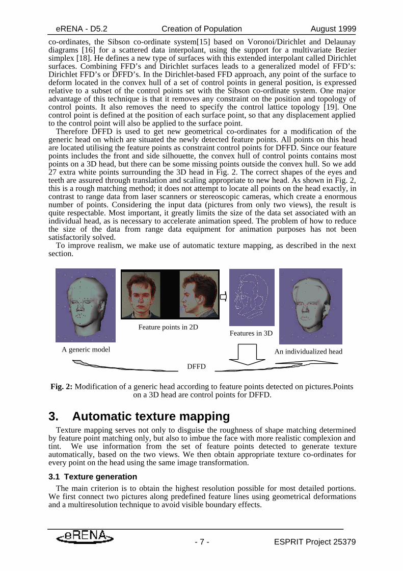
ordinates for points densely distributed on the head. In most cases, we know the location ofonly a few visible features such as eyes, lips and silhouettes, key characteristics forrecognising people. We call them as feature points whose location can be detected eitherautomatically or at least interactively. Our process is semi-automatic. It means that most ofthe tedious processing is done automatically and that only minor manual adjustment arenecessary to complete the models To reconstruct a photographically realistic head, ready foranimation, we detect corresponding feature points on both of two orthogonal images—frontand side—and deduce their 3D positions. This information is used to modify a generic modelthrough a geometrical deformation. Feature detection is processed in a semiautomatic wayusing the structured snake method [9] with some anchor functionality. Fig. 2 depicts anorthogonal pair of normalised images, showing the features detected. Here normalisationsignifies locating images in the feature point space, so that the front and side views of a headhave the same height. The feature points are overlaid on the images even though they arelocated in spaces with different origins and scales from the images.
The two 2D sets of position co-ordinates, from front and side views, i.e., the (x, y) and the(z, y) planes, are combined to give a single set of 3D points. To get perfectly aligned andorthogonal views is almost impossible, and this leads to difficulties in determining the (x, y, z)co-ordinates of a point from the (x, y) on the front image and the (y, z) on the side image.Taking the average of the two points often results in an unnatural face shape. Thus we relymainly on the front y co-ordinate, using the side y only when we do not have front one. Thisconvention is very effective when applied to almost orthogonal pairs of images. In addition,for asymmetrical faces, this convention allows for retention of the asymmetry with regard tothe most salient features, even though a single side image is used in reconstructing both theright and left aspects of the face.
A global transformation moves the 3D feature points to the space containing the generichead, which is a normalisation of every head.
2.2 Modification of a generic modelWe have a certain set of 3D feature points, which has about 160 points. The problem is how
to deform a generic model, which has more than a thousand points to make an individualisedsmooth surface. One solution is to use 3D feature points as a set of control points for adeformation. Then the deformation of a surface can be seen as an interpolation of thedisplacements of the control points.
Free-Form Deformations (FFD)[14] belong to a wider class of geometric deformation tools.However FFD has a serious constraint in that control points boxes have to be rectangular,which limits the expression of any point of the surface to deform relative to the control pointsbox. Farin [17] extends the natural neighbours’ interpolant based on the natural neighbours’
eRENA - D5.2 Creation of Population August 1999
- 7 - ESPRIT Project 25379
co-ordinates, the Sibson co-ordinate system[15] based on Voronoi/Dirichlet and Delaunaydiagrams [16] for a scattered data interpolant, using the support for a multivariate Beziersimplex [18]. He defines a new type of surfaces with this extended interpolant called Dirichletsurfaces. Combining FFD’s and Dirichlet surfaces leads to a generalized model of FFD’s:Dirichlet FFD’s or DFFD’s. In the Dirichlet-based FFD approach, any point of the surface todeform located in the convex hull of a set of control points in general position, is expressedrelative to a subset of the control points set with the Sibson co-ordinate system. One majoradvantage of this technique is that it removes any constraint on the position and topology ofcontrol points. It also removes the need to specify the control lattice topology [19]. Onecontrol point is defined at the position of each surface point, so that any displacement appliedto the control point will also be applied to the surface point.
Therefore DFFD is used to get new geometrical co-ordinates for a modification of thegeneric head on which are situated the newly detected feature points. All points on this headare located utilising the feature points as constraint control points for DFFD. Since our featurepoints includes the front and side silhouette, the convex hull of control points contains mostpoints on a 3D head, but there can be some missing points outside the convex hull. So we add27 extra white points surrounding the 3D head in Fig. 2. The correct shapes of the eyes andteeth are assured through translation and scaling appropriate to new head. As shown in Fig. 2,this is a rough matching method; it does not attempt to locate all points on the head exactly, incontrast to range data from laser scanners or stereoscopic cameras, which create a enormousnumber of points. Considering the input data (pictures from only two views), the result isquite respectable. Most important, it greatly limits the size of the data set associated with anindividual head, as is necessary to accelerate animation speed. The problem of how to reducethe size of the data from range data equipment for animation purposes has not beensatisfactorily solved.
To improve realism, we make use of automatic texture mapping, as described in the nextsection.
A generic model
Feature points in 2D
An individualized head
DFFD
Features in 3D
Fig. 2: Modification of a generic head according to feature points detected on pictures.Pointson a 3D head are control points for DFFD.
3. Automatic texture mappingTexture mapping serves not only to disguise the roughness of shape matching determined
by feature point matching only, but also to imbue the face with more realistic complexion andtint. We use information from the set of feature points detected to generate textureautomatically, based on the two views. We then obtain appropriate texture co-ordinates forevery point on the head using the same image transformation.
3.1 Texture generationThe main criterion is to obtain the highest resolution possible for most detailed portions.
We first connect two pictures along predefined feature lines using geometrical deformationsand a multiresolution technique to avoid visible boundary effects.
eRENA - D5.2 Creation of Population August 1999
- 8 - ESPRIT Project 25379
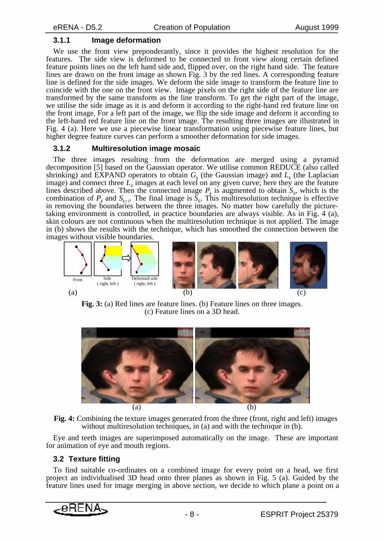
3.1.1 Image deformationWe use the front view preponderantly, since it provides the highest resolution for the
features. The side view is deformed to be connected to front view along certain definedfeature points lines on the left hand side and, flipped over, on the right hand side. The featurelines are drawn on the front image as shown Fig. 3 by the red lines. A corresponding featureline is defined for the side images. We deform the side image to transform the feature line tocoincide with the one on the front view. Image pixels on the right side of the feature line aretransformed by the same transform as the line transform. To get the right part of the image,we utilise the side image as it is and deform it according to the right-hand red feature line onthe front image. For a left part of the image, we flip the side image and deform it according tothe left-hand red feature line on the front image. The resulting three images are illustrated inFig. 4 (a). Here we use a piecewise linear transformation using piecewise feature lines, buthigher degree feature curves can perform a smoother deformation for side images.
3.1.2 Multiresolution image mosaicThe three images resulting from the deformation are merged using a pyramid
decomposition [5] based on the Gaussian operator. We utilise common REDUCE (also calledshrinking) and EXPAND operators to obtain Gk (the Gaussian image) and Lk (the Laplacianimage) and connect three Lk images at each level on any given curve; here they are the featurelines described above. Then the connected image Pk is augmented to obtain Sk, which is thecombination of Pk and Sk+1. The final image is S0. This multiresolution technique is effectivein removing the boundaries between the three images. No matter how carefully the picture-taking environment is controlled, in practice boundaries are always visible. As in Fig. 4 (a),skin colours are not continuous when the multiresolution technique is not applied. The imagein (b) shows the results with the technique, which has smoothed the connection between theimages without visible boundaries.
Front Side ( right, left )
Deformed side( right, left )
(a) (b) (c)
Fig. 3: (a) Red lines are feature lines. (b) Feature lines on three images.(c) Feature lines on a 3D head.
(a) (b)
Fig. 4: Combining the texture images generated from the three (front, right and left) imageswithout multiresolution techniques, in (a) and with the technique in (b).
Eye and teeth images are superimposed automatically on the image. These are importantfor animation of eye and mouth regions.
3.2 Texture fittingTo find suitable co-ordinates on a combined image for every point on a head, we first
project an individualised 3D head onto three planes as shown in Fig. 5 (a). Guided by thefeature lines used for image merging in above section, we decide to which plane a point on a

eRENA - D5.2 Creation of Population August 1999
- 9 - ESPRIT Project 25379
3D head is to be projected. The points projected on one of three planes are then transferred toeither the front or the side 2D-feature point space. Finally, one more transform on the imagespace is processed to obtain the texture co-ordinates and the final mapping of points on atexture image is generated. The origins of each space are also shown in Fig. 5 (a). The 3Dhead space is the space for the 3D head model, the 2D feature point space is the one forfeature points used for feature detection, the 2D image space is the one for the orthogonalimages used for input, and the 2D texture image space is for the generated image space. The2D-feature point space is different from the 2D-image space even though they are displayedtogether in Fig. 5 (a).
The final texture fitting on a texture image is shown in Fig. 5 (b). The final texture mappingresults in smoothly connected images inside triangles of texture co-ordinate points, which areaccurately positioned. The eye and teeth fitting process are done with predefined co-ordinatesand transformations related to the texture image size. After doing this once for a genericmodel, it is fully automated. The brighter points in Fig. 5 (b) correspond to feature points andthe triangles are a projection of triangular faces on a 3D head. Since our generic model isendowed with a triangular mesh, the texture mapping benefits from an efficient triangulationof texture image containing finer triangles over the highly curved and/or highly articulatedregions of the face and larger triangles elsewhere, as in the generic model. This triangulationis also used for the 3D-image morphing in Section 0.
front
leftright
3D Head space2D Feature
Points space2D Image space(input pictures)
front
side
front
side
Textureimage
2D texture Image space(generated image)
Feature lines
Top view of a 3D head
(a) (B)
Fig. 5: (a) Texture fitting giving a texture co-ordinate on an image for each point on a head.(b) Texture co-ordinates overlaid on a texture image.
3.3 Cloning ResultsFig. 6 shows several views of the head reconstructed from the two pictures in Fig. 2.
Fig. 6: Snapshots of a reconstructed head in several views.
Other examples covering wide range of age and many kinds of ethnic group are shown inFig. 7. Every face in this report is modified from the SAME generic model shown in Fig. 5.How individualised the representations are depends on how many feature points are identifiedon the input pictures. Our generic model currently does not have many points on the“hairdo”, so it is not easy to vary hair length, for example.

eRENA - D5.2 Creation of Population August 1999
- 10 - ESPRIT Project 25379
Fig. 7: Examples of reconstructed heads from pictures. Two views of each virtual humanare shown just after two photos of the corresponding real person. These are ready for
immediate animation in a virtual world.
As an example of the cloning capabilities we have asked the member of the eRENAconsortium to send us photos in order to clone them and used their face in the future for thecreation of the population. Results from cloning are presented in Fig. 8.

eRENA - D5.2 Creation of Population August 1999
- 11 - ESPRIT Project 25379
Fig. 8 Examples of cloned head of eRENA participants
3.4 Real-time animationReal-time animation means that the virtual human can be animated according to facial or
body parameters and that it will be displayed on the computer screen at more than 10 framesper second in its virtual environment. Real-time is important for animation but the cloningand population creation can be done completely offline and then loaded later in the virtual
environment. The predefined regions [27] of the generic model are associated withanimation information, which can be directly transported to the heads constructed from it bygeometrical
modification in Section 0. Fig. 9 shows several expressions on a head reconstructed fromthree pictures.
Fig. 9: Examples of a reconstructed head from three photos and several expressions.
4. Statistical methods to generate a largepopulation
The statistical methods provide efficient tools for automatically generate a large population.The ideas and objectives of this method are similar to the method that will be presented in thenext chapter but they rely heavily however on specific biostatistical notions. This notion arerelated specifically to face features and when extracted provide an efficient way of basicallyrepresenting a “type” of person. The dynamic morphing system is not considering those
eRENA - D5.2 Creation of Population August 1999
- 12 - ESPRIT Project 25379
aspects or more precisely is not based upon those basic principles but may have the similarresults, as it will be explained in the next chapter. Those two methods are thereforecomplementary rather that opposed.
4.1 Constructing and sampling from an hypothetical populationOur approach to generating populations is based on biostatistical notions of morphological
variation within a community. The underlying hypothesis is that if we determine a largenumber of facial measurements, these will be approximately distributed in the populationaccording to a multivariate normal distribution, where most of the variation can be located ina few orthogonal dimensions. These dimensions can be inferred by principal componentanalysis [37] applied to measurements of relatively few input heads. A random sample fromthe reduced distribution over the space spanned by the principal component yields the facialmeasurements of a new head, typical of the population.
An input head is described by its set of feature points obtained interactively fromphotographs as explained in Section 0. The principal component analysis will generate newsets of feature points having original positions and therefore describing the geometry of newheads. These new samples will be used to modify the shape of a generic model with the sameway as in Section 0. Fig. 1 shows how principal component analysis is used inside thepopulation generation process.
For a realistic morphological variation, it is better to use a large number of heads. Wecurrently use 30 heads representatives of an average population (15 males / 15 females, 15Asian / 15 Caucasian) but we are continuously increasing this number using the face ofcloned visiting persons to our lab or during events such as the CEBIT fair in Hanover (1999).
4.1.1 InferenceThe feature points are divided into subset according to the head region where they are
defined (mouth, eye, nose, cheek, and etc.). Two sets of pre-specified 3D vectors representingdistances between feature points are calculated for each head. The first set reflects the overallshape parameters and consists of distances between a central point situated on the nose and
local points, each of them belonging to a different region. The second set represents localrelationships and corresponds to distances defined between a local point and the points beingin the same region as shown in Fig. 10.
Denote by n the total number of measurements represented by the central point co-ordinatesand distance vectors co-ordinates and denote by H the number of input heads. Themeasurements for the H heads are each standardised to Normal [0,1] and entered into an H xn matrix M. The principal components of variation are found using standard procedures,involving the decomposition XLXt=MMt, where X is orthonormal and L contains theeigenvalues in decreasing order. Only those dimensions of X with non-negligible eigenvalues,i.e. the principal components, are retained.
4.1.2 SamplingFor each head in the population being constructed, independent samples are drawn using a
one-dimensional sampling distribution (N[0,1]) on each principal component axis. The i-thcomponent is multiplied by sqrt(Li), where Li is the i-th eigenvalue of the i-th axis, and thefeature point distance vectors are then constructed by inverting the transformation to X fromthe original measurement co-ordinates in n-dimensional space, and then inverting thestandardisation process for each measurement. It is then straightforward to recover all thenew feature points from the n measurements, starting with the central point on the nose.
Sampling from the principal component space is a rapid method for generating any numberof feature point sets. We currently use 160 feature points. The matrix MMt has a dimension of160 x 3. It is decomposed in less than one minute on a computer with at today’s performance.

eRENA - D5.2 Creation of Population August 1999
- 13 - ESPRIT Project 25379
Fig. 10: 3D vectors representing distances between feature points. Arrows from nose tip tofacial region centre (forehead, cheek, and mouth on the Fig.) represent global distances.Arrows from region centre to local feature points represent local distances.
5. 3D morphing for creating various individualsMorphing technology has seen a great deal of development, both in 2D and 3D. Very high
quality morphing between people or animals is available in 2D, while in 3D, it has beenapplied mainly to pairs of objects with differing topology. In this report, we vary aspects ofboth 2D and 3D representations in creating new virtual faces. When we morph one person toanother in 3D, we must deal with alteration in both shape and texture. Since every face
created through the methods described here shares the same topology, it is relatively easy tovary head shapes in 3D just using a simple linear interpolation of 3D co-ordinates. On theother hand, it is less straightforward to carry out 2D morphing of textures since this requiressome feature information specifying correspondences between specific points in the twoimages. Here we use a surprisingly simple method, drawing on 3D information to facilitate2D morphing among texture images.
5.1 Texture morphingFor the heads newly created through sampling in the principal component space, we do not
have source images to generate texture mapping. For this case we use texture polymorph witha given set of cloned heads with textures. Image morphing normally considers featurespecification, warp generation, and transition control. When we, however, use texture imagewith 3D head information, feature specification and warp generations are automatically givenby 3D head topology and only a simple calculation based on triangulation with given ratiosamong input texture images is performed.
Two steps are necessary to obtain texture morphing. First, texture co-ordinates areinterpolated, and then image morphing is carried out. We use simple linear interpolationamong several texture co-ordinate sets.
eRENA - D5.2 Creation of Population August 1999
- 14 - ESPRIT Project 25379
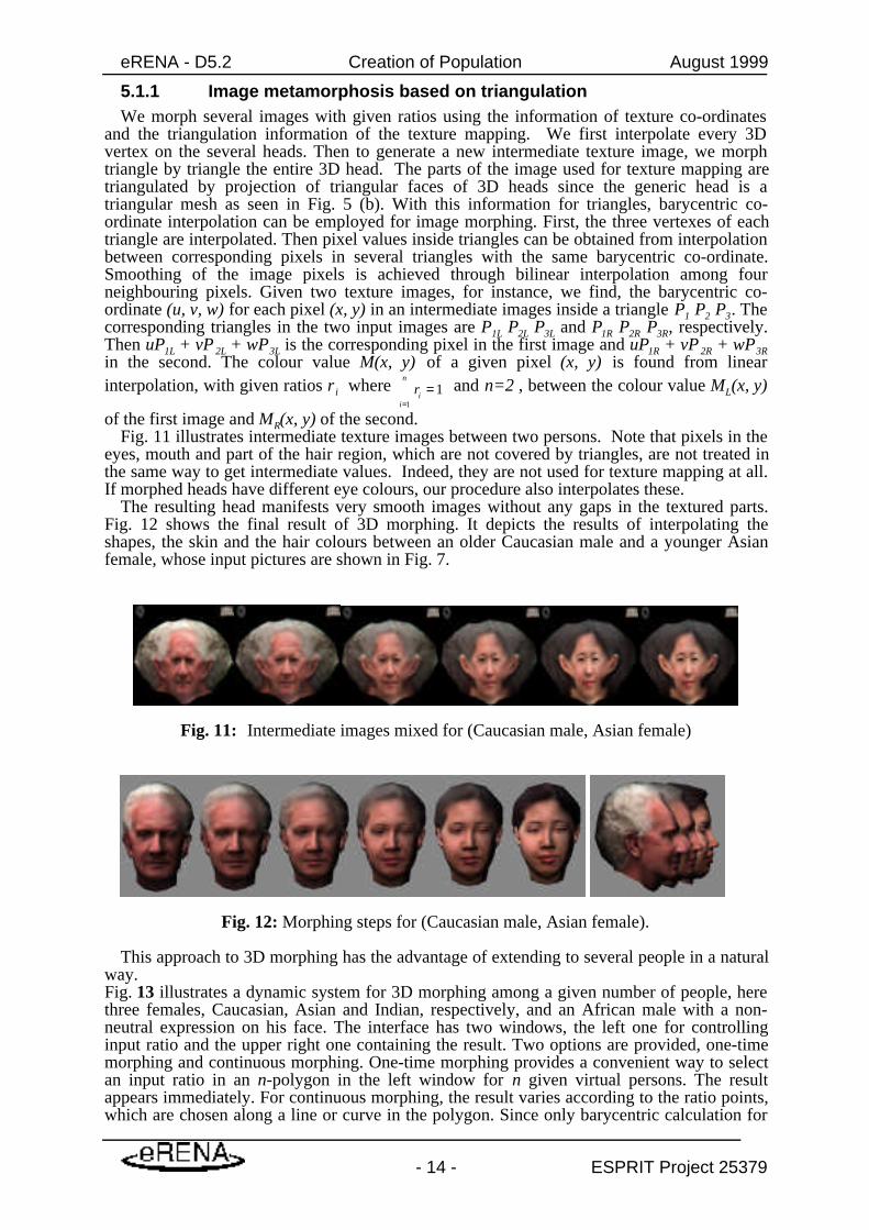
5.1.1 Image metamorphosis based on triangulationWe morph several images with given ratios using the information of texture co-ordinates
and the triangulation information of the texture mapping. We first interpolate every 3Dvertex on the several heads. Then to generate a new intermediate texture image, we morphtriangle by triangle the entire 3D head. The parts of the image used for texture mapping aretriangulated by projection of triangular faces of 3D heads since the generic head is atriangular mesh as seen in Fig. 5 (b). With this information for triangles, barycentric co-ordinate interpolation can be employed for image morphing. First, the three vertexes of eachtriangle are interpolated. Then pixel values inside triangles can be obtained from interpolationbetween corresponding pixels in several triangles with the same barycentric co-ordinate.Smoothing of the image pixels is achieved through bilinear interpolation among fourneighbouring pixels. Given two texture images, for instance, we find, the barycentric co-ordinate (u, v, w) for each pixel (x, y) in an intermediate images inside a triangle P1 P2 P3. Thecorresponding triangles in the two input images are P1L P2L P3L and P1R P2R P3R, respectively.Then uP1L + vP 2L + wP3L is the corresponding pixel in the first image and uP1R + vP 2R + wP3Rin the second. The colour value M(x, y) of a given pixel (x, y) is found from linearinterpolation, with given ratios r i where 1
1
=�=
n
iir and n=2 , between the colour value ML(x, y)
of the first image and MR(x, y) of the second.Fig. 11 illustrates intermediate texture images between two persons. Note that pixels in the
eyes, mouth and part of the hair region, which are not covered by triangles, are not treated inthe same way to get intermediate values. Indeed, they are not used for texture mapping at all.If morphed heads have different eye colours, our procedure also interpolates these.
The resulting head manifests very smooth images without any gaps in the textured parts.Fig. 12 shows the final result of 3D morphing. It depicts the results of interpolating theshapes, the skin and the hair colours between an older Caucasian male and a younger Asianfemale, whose input pictures are shown in Fig. 7.
Fig. 11: Intermediate images mixed for (Caucasian male, Asian female)
Fig. 12: Morphing steps for (Caucasian male, Asian female).
This approach to 3D morphing has the advantage of extending to several people in a naturalway.Fig. 13 illustrates a dynamic system for 3D morphing among a given number of people, herethree females, Caucasian, Asian and Indian, respectively, and an African male with a non-neutral expression on his face. The interface has two windows, the left one for controllinginput ratio and the upper right one containing the result. Two options are provided, one-timemorphing and continuous morphing. One-time morphing provides a convenient way to selectan input ratio in an n-polygon in the left window for n given virtual persons. The resultappears immediately. For continuous morphing, the result varies according to the ratio points,which are chosen along a line or curve in the polygon. Since only barycentric calculation for

eRENA - D5.2 Creation of Population August 1999
- 15 - ESPRIT Project 25379
texture image pixels is required, the calculation is very fast. There is also an option to seton/off for shape and image variation rate separately.
Fig. 13: A dynamic system for 3D morphing. Here four persons are used for continuousmorphing following a user-specified curve.
A key to the efficiency of this system is the restriction that all the heads share the samestructure. A benefit is that the user can experiment with the ratios for mixing two or moreheads in real-time.
6. Results of large populationWe report here on experiments with cloning and the creation of new heads out of cloned
one. We used seven orthogonal photo sets as inputs. Fig. 7 shows the input photos and outputreconstructed virtual faces. This includes four Caucasians of various ages, an Indian, anAsian, and an African. There are three adult females, three adult males and a child. Thecreation of a population is illustrated in Fig. 14. The 42 faces, some of whom have non-neutral facial expressions, are generated from the H=7 sets of orthogonal photos in Fig. 7according to the steps schematised in Fig. 1. All faces are ready to be animated. The size ofthe texture image for each person is 256x256, which is less than 10 KB. The total amount ofdata for the heads in OpenInventor format is rather small considering their realisticappearance. The size of Inventor format (corresponding to VRML format) is about 200 KB.The texture image is stored in JPEG format and has sized about 5~50 KB depending on thequality of pictures; all examples shown in this report have size less than 45 KB. The numberof points on a head is 1257, where 192 of them are for teeth and 282 of them are used for thetwo eyes. This leaves only 783 points for the individualisation of the face surface aside fromeyes and teeth.
The small size of data used in the face geometry and texture gives us the possibility ofanimating several heads together in real time.
Fig. 15 shows a snapshot of an OpenGL-based interface allowing the animation of a fewheads. Every head has its own location and script file, which defines several continuousexpressions (like eye, eyebrow, mouth movement or head rotation) with a given range oftime. The expressions repeat with different frequency for each head. . In this interface, up to 5heads can be animated in real-time. With smaller size of texture images and fewer points onheads, we will certainly increase number of heads for real-time animation.

eRENA - D5.2 Creation of Population August 1999
- 16 - ESPRIT Project 25379
Fig. 14: Forty-two virtual faces created from seven faces reconstructed from images.
eRENA - D5.2 Creation of Population August 1999
- 17 - ESPRIT Project 25379
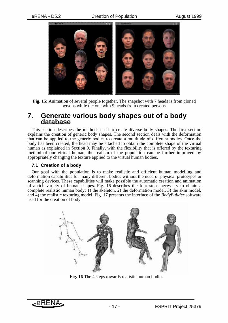
Fig. 15: Animation of several people together. The snapshot with 7 heads is from clonedpersons while the one with 9 heads from created persons.
7. Generate various body shapes out of a bodydatabase
This section describes the methods used to create diverse body shapes. The first sectionexplains the creation of generic body shapes. The second section deals with the deformationthat can be applied to the generic bodies to create a multitude of different bodies. Once thebody has been created, the head may be attached to obtain the complete shape of the virtualhuman as explained in Section 0. Finally, with the flexibility that is offered by the texturingmethod of our virtual human, the realism of the population can be further improved byappropriately changing the texture applied to the virtual human bodies.
7.1 Creation of a bodyOur goal with the population is to make realistic and efficient human modelling and
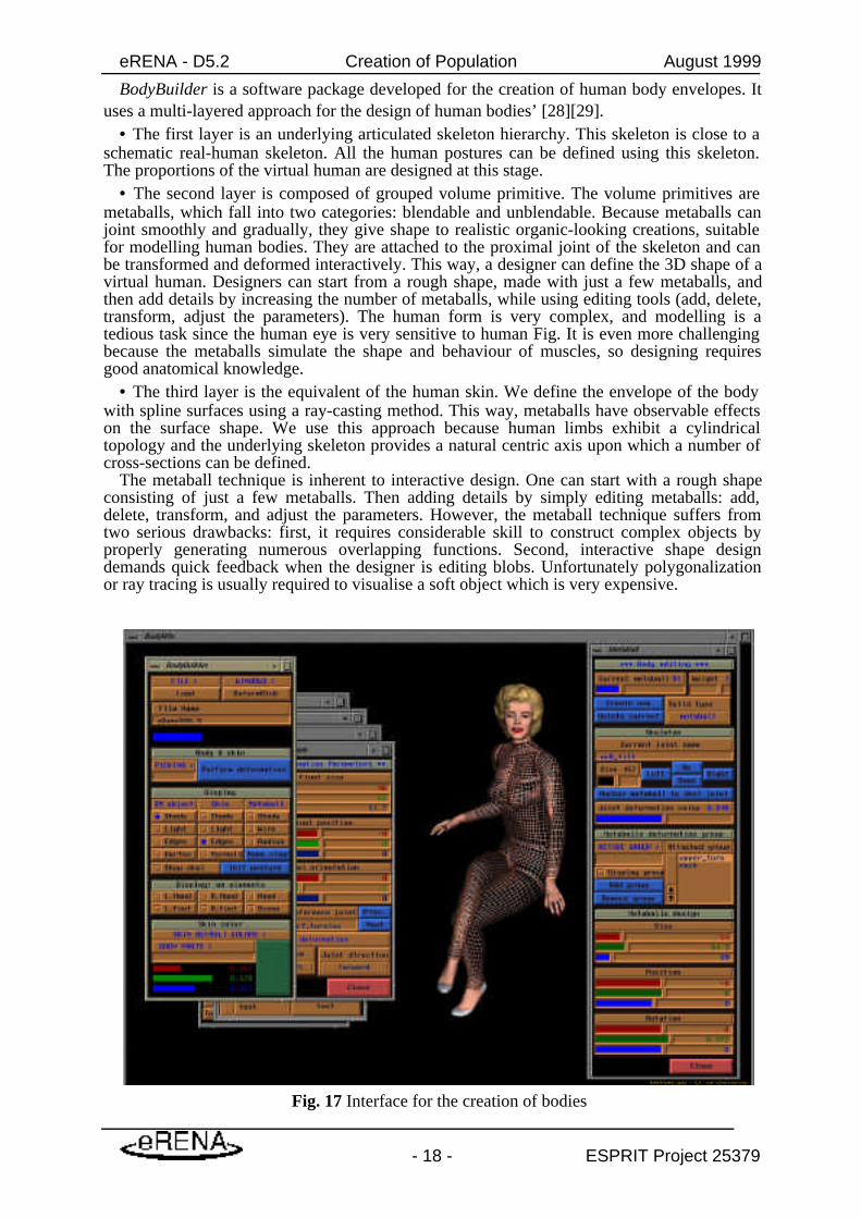
deformation capabilities for many different bodies without the need of physical prototypes orscanning devices. These capabilities will make possible the automatic creation and animationof a rich variety of human shapes. Fig. 16 describes the four steps necessary to obtain acomplete realistic human body: 1) the skeleton, 2) the deformation model, 3) the skin model,and 4) the realistic texturing model. Fig. 17 presents the interface of the BodyBuilder softwareused for the creation of body.
Fig. 16 The 4 steps towards realistic human bodies
eRENA - D5.2 Creation of Population August 1999
- 18 - ESPRIT Project 25379
BodyBuilder is a software package developed for the creation of human body envelopes. Ituses a multi-layered approach for the design of human bodies’ [28][29].
• The first layer is an underlying articulated skeleton hierarchy. This skeleton is close to aschematic real-human skeleton. All the human postures can be defined using this skeleton.The proportions of the virtual human are designed at this stage.
• The second layer is composed of grouped volume primitive. The volume primitives aremetaballs, which fall into two categories: blendable and unblendable. Because metaballs canjoint smoothly and gradually, they give shape to realistic organic-looking creations, suitablefor modelling human bodies. They are attached to the proximal joint of the skeleton and canbe transformed and deformed interactively. This way, a designer can define the 3D shape of avirtual human. Designers can start from a rough shape, made with just a few metaballs, andthen add details by increasing the number of metaballs, while using editing tools (add, delete,transform, adjust the parameters). The human form is very complex, and modelling is atedious task since the human eye is very sensitive to human Fig. It is even more challengingbecause the metaballs simulate the shape and behaviour of muscles, so designing requiresgood anatomical knowledge.
• The third layer is the equivalent of the human skin. We define the envelope of the bodywith spline surfaces using a ray-casting method. This way, metaballs have observable effectson the surface shape. We use this approach because human limbs exhibit a cylindricaltopology and the underlying skeleton provides a natural centric axis upon which a number ofcross-sections can be defined.
The metaball technique is inherent to interactive design. One can start with a rough shapeconsisting of just a few metaballs. Then adding details by simply editing metaballs: add,delete, transform, and adjust the parameters. However, the metaball technique suffers fromtwo serious drawbacks: first, it requires considerable skill to construct complex objects byproperly generating numerous overlapping functions. Second, interactive shape designdemands quick feedback when the designer is editing blobs. Unfortunately polygonalizationor ray tracing is usually required to visualise a soft object which is very expensive.
Fig. 17 Interface for the creation of bodies

eRENA - D5.2 Creation of Population August 1999
- 19 - ESPRIT Project 25379
In order to enhance the modelling capability of the metaball technique, we devised someways to reduce the number of metaballs needed for a desired detail shape and to allow thedesigner to manipulate body surface at interactive speed. A cross-sectional based isosurface-sampling method, combined with the B-spline blending, enable us to achieve those two goals.
From a practical point-of-view, an interactive metaball editor for shape designers is written.We start the shape design by first creating a skeleton for the organic body to be modelled.Metaballs are used to approximate the shape of internal structures, which have observableeffects on the surface shape. Each metaball is attached to its proximal joint, defined in thejoint local co-ordinate system of the underlying skeleton which offers a convenient referenceframe for position and editing metaball primitives, because the relative proportion,orientation, and size of different body parts is already well-defined.
In our editor, the workstation can display shaded or wireframe colour metaballs and highresolution body envelope near real time. Metaballs are displayed as ellipsoids either witheffective radius or threshold radius. The ‘threshold’ mode shows the visible size of metaballs,while the ‘effective’ mode shows how far the metaball will influence. Some widget panels areused to interactively adjust the size, weight, position, and orientation of metaballs. SpaceBallor trackball enables the user to rotate models around in space for different viewing. Byturning on/off various display entities of different layers, the designer can selectively checkskeleton, metaballs, cross-section contours, and skin envelope simultaneously. The designercan interactively create, delete, pick, and joint attach/detach metaballs. A file format isdesigned which can store both joint hierarchy and metaball information. Models can be savedto a file and load in later for successive sculpting. The designer can get quick feedback of theresulting skin form. Fig. 18 presents two examples of created man and woman bodies. In Fig.19, the examples of small and large virtual humans are presented.
Fig. 18 Examples of man and woman bodies
eRENA - D5.2 Creation of Population August 1999
- 20 - ESPRIT Project 25379
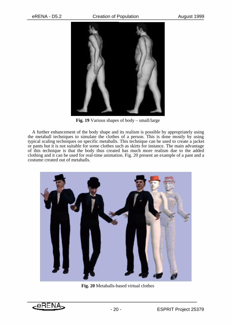
Fig. 19 Various shapes of body – small/large
A further enhancement of the body shape and its realism is possible by appropriately usingthe metaball techniques to simulate the clothes of a person. This is done mostly by usingtypical scaling techniques on specific metaballs. This technique can be used to create a jacketor pants but it is not suitable for some clothes such as skirts for instance. The main advantageof this technique is that the body thus created has much more realism due to the addedclothing and it can be used for real-time animation. Fig. 20 present an example of a pant and acostume created out of metaballs.
Fig. 20 Metaballs-based virtual clothes

eRENA - D5.2 Creation of Population August 1999
- 21 - ESPRIT Project 25379
7.2 How to simply create diverse shapesThe body creation interface includes also various transformations that can be easily applied
to an already constructed body. Fig. 21 presents the most typical transformations. The firstand most important transformation is the global scaling that allows the creation of child bodyto normal height human bodies. Using the frontal and lateral scaling, we can easily createvirtual humans with normal characteristic towards much stronger built humans. Finally theorigin of the spine may be changed to create different ratio between the torso and the legs.Extreme examples are displayed in Fig. 21.
Fig. 21 Available transformation to change the body shape
7.3 Connecting the head to the bodyIn the previous sections, we have explained how we could obtain various heads and body
shapes. In this section we will explain how we can position those heads and attached them tothe bodies.
Because of the disparity between bodies and heads, we do not include the neck with any ofthem. Therefore the neck must be created automatically according to the relative position ofthe head and body. The first step is therefore to position the head relatively to the body usinga suitable matrix of transformation. This matrix is usually available when the body is createdbut it may be changed if necessary. The automatic program for the creation of the neckproceeds then first by identifying the vertex on the head where the neck will be attached.Because the number of vertices on the body and on the head may vary with from one instanceto another, a neighbouring technique is used to find the ordered n-to-m relationship betweenthe neck vertexes on the body and on the head. This relationship is finally used to generate theneck mesh that links the head to the body. The mesh thus created has a generic procedure forits deformation according to the value of the head rotation.
Fig. 22 displays an example of a created neck that connects the body to the head.
Fig. 22 Neck connection between the body and the head
eRENA - D5.2 Creation of Population August 1999
- 22 - ESPRIT Project 25379
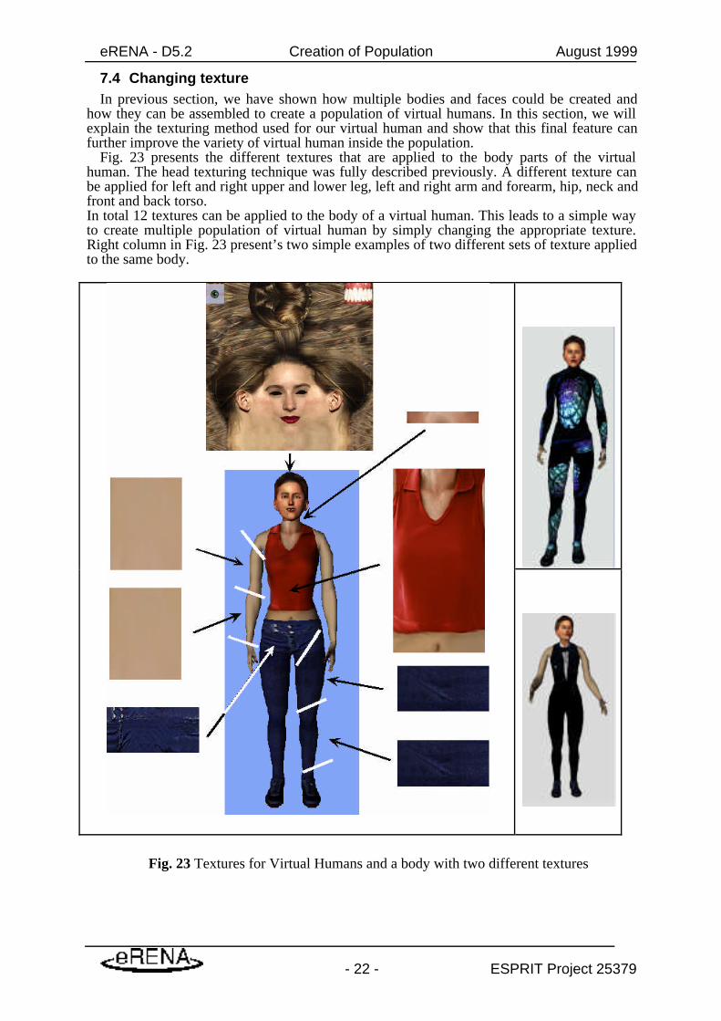
7.4 Changing textureIn previous section, we have shown how multiple bodies and faces could be created and
how they can be assembled to create a population of virtual humans. In this section, we willexplain the texturing method used for our virtual human and show that this final feature canfurther improve the variety of virtual human inside the population.
Fig. 23 presents the different textures that are applied to the body parts of the virtualhuman. The head texturing technique was fully described previously. A different texture canbe applied for left and right upper and lower leg, left and right arm and forearm, hip, neck andfront and back torso.In total 12 textures can be applied to the body of a virtual human. This leads to a simple wayto create multiple population of virtual human by simply changing the appropriate texture.Right column in Fig. 23 present’s two simple examples of two different sets of texture appliedto the same body.
Fig. 23 Textures for Virtual Humans and a body with two different textures

eRENA - D5.2 Creation of Population August 1999
- 23 - ESPRIT Project 25379
7.5 Examples of complete virtual humans
Fig. 24 Example of bodies with Heads
In Fig. 24, we present several examples of various bodies (male and female) with severalheads placed on top of them. These complete models are ready to be animated because theyare based upon generic models and that the animation parameters are embedded within thedefinition of the body and head files. Depending upon the kind of population that we would

eRENA - D5.2 Creation of Population August 1999
- 24 - ESPRIT Project 25379
like to simulate, it is possible to change various parameters, such as height of a virtual human,to obtain new models ready to be animated.
8. ConclusionWe have introduced a complete set of methods for the generation of large populations of
realistic faces, enabled for immediate real-time animation, from just a few pairs of orthogonalpictures [38][39][40][41][42]. One key to our technique is the efficient reconstruction ofanimation-ready individualised faces fitted with seamless textures. This involves shapeacquisition through the modification of a generic model and texture fitting through geometricdeformation of an orthogonal pair of texture images, followed by multiresolution procedures.This technique was robust enough to allow one operator to clone some 100 individuals on PCplatform in five days at CEBIT in Hanover on invitation by the “Hanover region”. Theprocedure is universal, applicable to men and women, adults and children, and different races,all using the same generic model.
To generate a population from a small number of heads such as those produced by thereconstruction technique, the first step is to characterise the shape in more detail using vectorsbetween feature points and to calculate the correlation matrix of these measurements.Principal component analysis is then applied to discover the statistical structure of this inputsample, namely a representation of the data in terms of a reduced number of significant (andindependent) dimensions of variability. Each point in this space, for example one chosen atrandom according to the probability distribution inferred from the input, determines all thefeature points and other characteristics of a new head. The representation of a population as aprobability distribution has great potential for allotting variation among face shapes intogender, age, race and residual components with eventual feedback to more realistic andefficient modelling.
All models generated in this system have the same topological structure, i.e. sametriangulation, for the 3D shape and similar characteristics for the texture images, enablingreal-time simulation of 3D metamorphosis among several virtual heads. Control of themixing ratio for shape and image is intuitive and the rotation in any view allows the fullappreciation of the 3D virtual heads. Various facial expressions can also be dynamicallymixed in this system.
Typical body shape were created for this project and we have shown how they could becombined together to create a population of person not only with different heads but also withdifferent bodies and texture. The creation of generic body shapes dealing with thedeformation is described. Once the body has been created, the head may be attached to obtainthe complete shape of the virtual human. Finally, with the flexibility that is offered by thetexturing method of our virtual human, the realism of the population can be further improvedby appropriately changing the texture applied to the virtual human bodies.
9. Link with eRENA ProjectThese virtual humans and population will be used in several performances scheduled in the
eRENA project in the future. We will make a link between the generation of individualisedpopulation and animation of crowds (animation is the work of the EPFL in this case). It isthen possible to simulate individualised populations according to individual and groupfeatures for various events.
The population of virtual avatars will be used during MIRALab’s performances atTelecom’99, Geneva, Switzerland in October. MIRALab will indeed be present not only atthe opening ceremony but will also give various performances during the complete week ofthe exposition, where people will be invited to be cloned and later appear as part of the showfor the other visitors of Telecom’99. MIRALab will be present at the booth of the city ofGeneva as well.

eRENA - D5.2 Creation of Population August 1999
- 25 - ESPRIT Project 25379
10. References[1] Douglas DeCarlo, Dimitris Metaxas and Matthew Stone, “An Anthropometric Face
Model using Variational Techniques”, In Computer Graphics (Proc. SIGGRAPH’98), pp. 67-74,1998.
[2] Brian Guenter, Cindy Grimm, Daniel Wood, “Making Faces”, In Computer Graphics (Proc.
SIGGRAPH’98), pp. 55-66, 1998.[3] Frederic Pighin, Jamie Hecker, Dani Lischinski, Richard Szeliski, David H. Salesin,
Synthesizing “Realistic Facial Expressions from Photographs”, In Computer Graphics (Proc.
SIGGRAPH’98), pp. 75-84, 1998.[4] http://www.turing.gla.ac.uk/turing/copyrigh.htm[5] Peter J. Burt and Edward H. Andelson, “A Multiresolution Spline with Application to Image Mosaics”,
ACM Transactions on Graphics, 2(4):217-236, Oct., 1983.
[6] Tsuneya Kurihara and Kiyoshi Arai, “A Transformation Method for Modeling and Animation of the
Human Face from Photographs”, In Proc. Computer Animation’91, Springer-Verlag Tokyo, pp. 45-58,1991.
[7] Yuencheng Lee, Demetri Terzopoulos, and Keith Waters, “Realistic Modeling for Facial Animation”, In
Computer Graphics (Proc. SIGGRAPH’96), pp. 55-62, 1996.
[8] Marc Proesmans, Luc Van Gool. “Reading between the lines - a method for extracting dynamic 3D
with texture”. In Proc. of VRST’97, pp. 95-102, 1997.
[9] Lee W. S., Kalra P., Magnenat-Thalmann N, “Model Based Face Reconstruction for Animation”, In
Proc. Multimedia Modeling (MMM’97), Singapore, pp. 323-338, 1997.
[10] J. Kent, W. Carlson , R. Parent, “Shape Transformation for Polygon Objects”, In Computer Graphics
(Proc. SIGGRAPH’92), pp. 47-54, 1992.
[11] Kiyoshi Arai, Tsuneya Kurihara, Ken-ichi Anjyo, “Bilinear interpolation for facial expression and
metamorphosis in real-time animation”, Visual Computer, Vol. 12, No. 3, 1996.
[12] S.-Y. Lee, K.-Y. Chwa, S.-Y. Shin, G. Wolberg, “Image metamorphosis using Snakes and Free-Form
deformations”, In Computer Graphics (Proc. SIGGRAPH’95), pp. 439-448, 1995.
[13] P. Fua, “Face Models from Uncalibrated Video Sequences”, In Proc. CAPTECH’98,pp. 215-228, 1998.
[14] Sederberg T. W., Parry S. R., “Free-Form Deformation of Solid Geometric Models”,In Computer Graphics (Proc. SIGGRAPH’86), pp. 151-160, 1986.
[15] Sibson R., “A Vector Identity for the Dirichlet Tessellation”, Math. Proc. CambridgePhilos. Soc., 87, pp. 151-155, 1980.
[16] Aurenhammer F., “Voronoi Diagrams - A Survey of a Fundamental Geometric DataStructure”, ACM Computing Survey, 23, 3, September 1991.
[17] Farin G., “Surface Over Dirichlet Tessellations”, Computer Aided Geometric Design,7, pp. 281-292, North-Holland, 1990.
[18] DeRose T.D., “Composing Bezier Simplexes”, ACM Transactions on Graphics, 7(3),pp. 198-221, 1988.
[19] Moccozet L., Magnenat Thalmann N., “Dirichlet Free-Form Deformations and theirApplication to Hand Simulation”, In Proc. Computer Animation’97, IEEE ComputerSociety, pp.93-102, 1997.
[20] George Wolberg, “Image morphing: a survey”, Visual Computer, InternationalJournal of Computer Graphics, Vol. 14, No. 8/9, pp.360-372, 1998.
[21] Wolberg G. “Digital image warping”, IEEE Computer Society Press, Los Anamitos,Calif, 1990.
[22] T. Beier, S. Neely, “Feature-based image metamorphosis”, In Computer Graphics (Proc.
SIGGRAPH’92), pp. 35-42, 1992.

eRENA - D5.2 Creation of Population August 1999
- 26 - ESPRIT Project 25379
[23] Arad N., Dyn N, Reisfeld D, Yeshurun Y. “Image warping by radial basis functions :applications to facial expressions”, CVGIP:Graph Models Image Processing, 56:161-172,1994.
[24] Litwinowicz P., Williams L., “Animating images with drawings”, In Computer Graphics(Proc. SIGGRAPH’94), pp. 409-412, 1994.
[25] Lee S., Chaw K-Y, Hahn J., Shin SY, “Image morphing using deformationtechniques”, Journal Visualization Computer Animation, 7:3-23, 1996.
[26] Gao P., Sederberg TW, “A work minimization approach to image morphing”, VisualComputer, International Journal of Computer Graphics, Vol. 14, No. 8/9, pp. 390-400,1998.
[27] Kalra P, Mangili A, Magnenat-Thalmann N, Thalmann D, “Simulation of FacialMuscle Actions Based on Rational Free Form Deformations”, Proc. Eurographics’92, pp.59-69, NCC Blackwell,1992.
[28] N. Magnenat-Thalmann, M.De Angelis, T. Hong, D. Thalmann, “DesignTransformation and Animation of Human Faces”, Visual Computer, Springer, Vol. 5, No.1-2, pp. 32-39, 1989. LeBlanc A.,
[29] Kalra P., Magnenat Thalmann N., Thalmann D., Sculpting With the “Ball & Mouse”Metaphor, Proc. Graphics Interface ‘91, Calgary, Canada, 1991.
[30] i Shen J., Thalmann D., Interactive Shape Design Using Metaballs and Splines, Proc.Implicit Surfaces 1995, Eurographics, Grenoble, France, 1995.
[31] N.M. Thalmann and D. Thalmann (1987) The Direction of Synthetic Actors in theFilm Rendez-vous a Montreal, IEEE CG&A, Vol.7, No12, pp.9-19.
[32] Komatsu K (1988) Human skin model capable of natural shape variation”, The VisualComputer, 3, pp.265-271
[33] Forsey DR (1991) A surface model for skeleton-based character animation, Proc.Second Eurographics Workshop on Animation and Simulation, Vienna, pp.55-71
[34] Bloomenthal J et al. (1993) Modeling, Visualizing, and Animating Implicit Surfaces,Siggraph’93 course notes
[35] Blinn J, A Generalization of Algebraic Surface Drawing, ACM Transactions onGraphics, Vol.1, pp.235-256
[36] Nishita T, Nakamae E (1994) A method of displaying metaballs by using Bézierclipping, Proc. Eurographics’94, pp.271-280.
[37] Kendall, M.G. and Stuart, A. Advanced Theory of Statistics, vol. 3. Griffin, 1976.[38] Won-Sook Lee, Yin Wu, Nadia Magnenat-Thalmann, “Cloning and Aging in a VR
Family”, Proc. IEEE VR’99 (Virtual Reality), Houston, Texas, March 13-17, 1999.[39] Won-Sook Lee, Marc Escher, Gael Sannier, Nadia Magnenat-Thalmann, “MPEG-4
Compatible Faces from Orthogonal Photos”, Proc. CA99 (International Conference onComputer Animation), Geneva, Switzerland. May 26-29, pp.186-194, 1999.
[40] G. Sannier, S. Balcisoy, N. Magnenat-Thalmann, D. Thalmann, “VHD: A System forDirecting Real-Time Virtual Actors”, The Visual Computer, Springer, 1999.
[41] Nadia Magnenat Thalmann, Prem Kalra, Marc Escher, Proceedings of the IEEE.VOL. 86, NO. 5. MAY 1998, “Face to Virtual Face”
[42] Won-Sook Lee, Elwin Lee, Nadia Magnenat Thalmann, Proc. Virtual Worlds 98,(Springer LNAI Press), Paris, pp.1-13, 1998. “Real Face Communication in a VirtualWorld”