deliverable 4.1 specification of integrated bms data ... · pdf fileoverview of existing data...
TRANSCRIPT
Deliverable 4.1 Specification of Integrated BMS Data
Models and Protocols selection
Revision : 1.0
Due date : 2011-12-31
Actual submission date : 2011-12-31
Lead Coordinator : NEC Europe Ltd.

Campus 21 ● D4.1 Specification of Integrated BMS Data Models and Protocols selection Page 1 of 25
2011-12-30
Deliverable Administration & Summary
No & name D4.1 Specification of Integrated BMS Data Models and
Protocols selection Status COMPLETE Due Date 2011-12-31
Author(s)
Mischa Schmidt, NEC Europe Ltd.
Anett Schülke, NEC Europe Ltd.
Cesar Valmaseda, CARTIF
Jose L. Hernandez Garcia, CARTIF
James Byrne, SIRUS
Editor NEC Europe Ltd.
DoW Task 4.1: Definition and Selection of Data Models, Protocols and Intelligent Functions for
Local Proxies NEC, Cartif, and SIRUS identify information flows and their content, map
them against existing standards for BIM, monitoring and control (e.g. IFC, BACnet,
ZigBee, or IP v6 LowPan). This task considers results from WP2 (monitoring concepts)
and WP3 (use case definition). The suitability of available protocols for advanced systems
integration is evaluated. Interfaces to communicate with the Data Warehouse Platform are
evaluated (different BACS versus unified interface), including protocols, data description,
and classification of privacy/security issues. Distributed functions of the business logic
and data models are selected based on the performance criteria (WP2) and use case
characteristics (WP3). Local proxy functionalities integrating with the existing BMS
subsystems are defined. This task uses results of WP2 and WP3.
Comments
Document history
V Date Author
Description
00 2011-10-10 MS Initial Outline
01 2011-10-28 MS Revised Skeleton referencing D2.1; BACnet information added
to protocols section; Valladolid information integrated by
Cartif
02 2011-11-07 MS Revised Skeleton swapping sections 7 and 8;
03 2011-11-15 MS Added Architecture
04 2011-11-23 MS Revised architecture; inserted IT reqs for architecture design
05 2011-11-28 MS Incorporated comments on architectural approaches, added
JAVA RMI Protocol considerations
06 2011-12-07 MS Changed Outline, added LonWorks and KNX sections
07 2011-12-07 MS Integrated Sirus input on UCC campus
08 2011-12-09 MS Added section on OPC
09 2011-12-15 AS Completion of State of the Art section with Information models
and protocols, drafting section 2 and 8
10 2011-12-16 AS Add section 3, re-organize section, review and adaption of
documents structure.
11 2011-12-16 MS Added IETF 6LoWPAN and COAP
12 2011-12-17 MS accepting changes, fixing editorials
13 2011-12-27 MS Polishing for Final document format
FINAL 2011-12-30 AS Including revision of section 3.2, Final version.

Campus 21 ● D4.1 Specification of Integrated BMS Data Models and Protocols selection Page 2 of 25
2011-12-30
Table of contents
1. Executive summary ............................................................................................... 3
2. Introduction ............................................................................................................ 4
2.1 Purpose and target group ........................................................................................ 4
2.2 Contributions of partners ......................................................................................... 4
2.3 Baseline, Relation to previous and future versions .................................................. 4
3. Challenges for the CAMPUS-21 System Design ................................................. 5
3.1 System Considerations ............................................................................................ 5
3.2 Valladolid Demonstration Site Overview .................................................................. 6
3.3 Cork Demonstration Site Overview .......................................................................... 6
4. State of the Art: Building Protocols and Information Data Models ................... 8
4.1 Building Protocol Standards .................................................................................... 8 4.1.1 Building Automation and Control Network (BACnet) ................................................. 8 4.1.2 KNX (Konnex) .......................................................................................................... 10 4.1.3 LonWorks ................................................................................................................. 11 4.1.4 Object Linking and Embedding (OLE) for Process Control (OPC) .......................... 12 4.1.5 Open Building Information Xchange (oBIX) ............................................................. 13 4.1.6 IETF 6LoWPAN and IETF CoAP ............................................................................. 14
4.2 Building Information Models .................................................................................. 14 4.2.1 Standardized Solutions ............................................................................................ 14 4.2.2 Proprietary Solutions ................................................................................................ 15
5. Intelligent Proxy Design ...................................................................................... 16
5.1 Layered High Level Proxy Design Architecture ...................................................... 16
5.2 Security and Privacy Requirements ....................................................................... 16
5.3 Intelligent Proxy Functional Architecture ................................................................ 18 5.3.1 Centralized Approach .............................................................................................. 19 5.3.2 Decentralized Approach ........................................................................................... 19 5.3.3 Evolutionary Approach ............................................................................................. 19
6. Preferences for CAMPUS-21 Integrated Protocol and Data Model ................. 21
6.1 Integrated Data Model considerations ................................................................... 21
6.2 Integrated Protocol considerations ........................................................................ 21
7. Conclusions ......................................................................................................... 22
7.1 Contribution to overall picture ................................................................................ 22
7.2 Relation to the state-of-the-art and progress beyond it .......................................... 22
7.3 Impacts to other WPs and Tasks ........................................................................... 22
8. Abbreviations ....................................................................................................... 23
9. References ........................................................................................................... 24

Campus 21 ● D4.1 Specification of Integrated BMS Data Models and Protocols selection Page 3 of 25
2011-12-30
1. EXECUTIVE SUMMARY
Campus-21 aims to provide an ICT-integration platform to integrate existing independently
functioning building management subsystems into a holistically managed monitoring and
control platform. Starting from the challenges given by the diversity and plurality of existing
BMS infrastructures in the industry, existing Information (Data) Models and protocols in the
Building Management industry are studied. The State-of-the-Art section will provide an
overview of existing data communication protocols strongly related to the existing
infrastructures at the planned CAMPUS-21 demo sites. Following up with the design of
intelligent proxies, the concept for de-centralized energy management aggregating over
legacy, as well as newly installable sensor systems, will be established. Based on the
complexity of the integrative approach, security requirements addressing the interaction
between components in the trusted domain, as well as between trusted and untrusted domains
are defined. These requirements also cover privacy concerns.
In consequence, this deliverable recommends for the usage of a harmonized protocol and
standardized information model as the basis for considerations of the CAMPUS-21 system
design integrating over the planned performance enhancements. D4.1 will only hand over the
results as recommendations towards the detailed design discussions in Task 4.2 as well as the
performance metrics studies in Task 2.2.

Campus 21 ● D4.1 Specification of Integrated BMS Data Models and Protocols selection Page 4 of 25
2011-12-30
2. INTRODUCTION
2.1 Purpose and target group
The scope of Deliverable D4.1 is to explore existing Information (Data) Models and
protocols in the Building Management industry. Considering the diversity of standardized as
well as proprietary BMS solutions, the focus of the protocol selection was influenced by the
existing installations at the testing sites, which allows to integrating existing BMS
subsystems in the CAMPUS-21 testing and evaluation phase. Initial results from the overview
of the existing monitoring infrastructure (performed in WP2 Task 2.1) have been taken into
account.
Considering the suitability and the scope for a harmonized approach across the diversity of
existing infrastructure, the purpose of this deliverable is to provide protocol and data model
guidance for the definition of the CAMPUS-21 system design in order to enforce performance
criteria defined in WP2 and realized for selected use cases (WP3) with the enhancements
studied in and provided by WP5 and WP6. Therefore, a selection of Information models and
protocols has been studied and several preferences will be recommended for the detailed
architecture and system definition in WP4 Task 4.2.
For the integration of existing BMS subsystems, an architectural approach using proxy
functions is defined. Distributed functions of the business logic are proposed with respect to a
variety to be defined performance criteria covering operational control and recommendations,
predictive recommendations and long-term performance evaluations.
2.2 Contributions of partners
The task D4.1 has been performed with the following contributions by the CAMPUS-21
partners:
• CARTIF: Contributions to existing monitoring protocols and data models with focus
on Valladolid demo site, contribution to high-level proxy design
• NEC Europe Ltd.: Description of existing protocols and data models (State-of-the-
Art), definition of proxy design and logical functional architecture, definition of high-
level system design and security requirements formulation
• SIRUS: Contributions to existing monitoring protocols and data models with focus on
UCC demo site; definition of high-level system design
2.3 Baseline, Relation to previous and future versions
Deliverable D4.1 provides together with D2.1 the starting point for the design of the
CAMPUS-21 data aggregation and communication system. The preferences communicated in
this deliverable will be further evaluated with the discussions and recommendations of Task
2.2 for the performance The results of D4.1 are preferences for the data aggregation layer,
which will be finally selected on the basis of the performance metrics for data taking and
control in deliverable D4.2.

Campus 21 ● D4.1 Specification of Integrated BMS Data Models and Protocols selection Page 5 of 25
2011-12-30
3. CHALLENGES FOR THE CAMPUS-21 SYSTEM DESIGN
3.1 System Considerations
Campus-21 aims to provide an ICT-integration platform to integrate existing independently
functioning building management subsystems into a holistically managed monitoring and
control platform. The challenge is given in the diversity of available industry standards, the
availability of multiple building management systems inside a single building running as
closed systems, and the lack of interoperability and cross-linked management of these inside
systems. Additionally, information from outside the buildings and interactions with adjacent
control systems in the neighbourhood are not considered yet while calibrating the buildings
for optimized energy performance.
External
Monitoring
Data Acquisition
External Service Information(weather, traffic, ..)
Legacy BMS
Monitoring and Control
BA
Cn
et
LO
N, K
NX
Enhanced Add-onMonitoring and Control
HistoricOperational
Applicationspecific
Local Building Performance ControlEvaluation, Optimization,
Recommendation, Maintenance
Local Domain
Acquisition
Tenants Services
BA
Cn
et
LO
N, K
NX
BMS jBMS 1
integrating
CAMPUS-21 control
and data acquisition
Trusted Domain
Untrusted Domains
External Optimization Resources
Remote BuildingPerformance Control
Evaluation, Recommendation,
Performance Logic
Building Operator Services
Facility Private CloudIn-Building
Public Cloud
Public Cloud
Figure 1: Overall CAMPUS-21 System approach
The CAMPUS-21 overall system design can be understood as a building supervisory control
and data acquisition (SCADA) system with an integrated concept for hierachical distributed
control. Figure 1 visualizes a high-level view of the approach for the system concept. Data
aquisition for a holistic monitoring concept has to accommodate the data collection from
existing BMS (historic as well as operational), from additional sensor systems installed based
on performance considerations, as well as from external monitoring systems. Looking on a
building centric approach, existing BMS systems establish a trusted domain in which the
CAMPUS-21 platform is also located. Note that the trusted building domain is a logical
domain which may extend to equipment physically located outside of the building (and

Campus 21 ● D4.1 Specification of Integrated BMS Data Models and Protocols selection Page 6 of 25
2011-12-30
likewise, an untrusted domain might extend to equipment physically located within the
building). Add-on sensoring should be located in this trusted doamin, and may have the
option to be integrated with the control layer of an existing BMS too. External monitoring
might be available (e.g. traffic control systems in the neighborhood), but with the restrictions
to be operating in and from an untrusted domain. Similiar security domain considerations
apply for the building performance management platform. The core in-building platform
components are hosted within the building trusted domain. Ensuring the usage of additional
resources (e.g. computing power) remote control components can be hosted in the trusted
domain (e.g. by the Facility manager’s private cloud) as an extension to the in-building core
platform. Further external resources – like information services (weather, traffic, pricing, ...)
or computation logic – need to follow the security guidance for the interaction between
trusted and untrusted domains. The data aquisition layer enables the collection of the raw data
over a harmonized communication protocol and the data mining based on a well-suited
infromation model. Discussions about existing industry standards and proprietary proposals
for protocols and information models will be presented in this deliverable.
To illustrate the diversity of the monitoring and control infrastructures in the testing and demo
sites of the CAMPUS-21 project, the following subsections will give a high level overview of
the demo sites in Valladolid/ Spain and Cork/ Ireland. Detailed information to all demo sites
are provided in the deliverable D2.1.
3.2 Valladolid Demonstration Site Overview
“Huerta del Rey” Sports Center is located at 9th Joaquin Velasco Martin Road at Valladolid
(Spain). This building was built in 1975 and it was the first Municipal Sports Center
conceived for the premier league competition of basketball and handball, as well as for sports
activities organized by the City Council. The building is composed by five volumes and
outdoor facilities such as tennis, paddle and football courts, as well as a car park and a green
beach. The standard sized sport hall for basketball and handball competition can
accommodate 3500 people. There is also a covered gym, and an indoor swimming pool with 8
lanes, 25 meters in length. Offices are used by “Sports Foundation of Valladolid” and it also
has a snack bar, located at ground floor and workshops. The total size including the whole
facilities is 9100m2. The Sport Center has 2 boilers (natural gas), a solar thermal plant with
165 flat panel (327,6 m2) and storage tanks with 26000 litters for heating and domestic hot
water (including the swimming pool). The HVAC system includes 7 Air Handling Units, 26
air heaters, 56 extract fans and ventilation supply fans; the office zone has iron radiators and
12 air conditioning machines. “Huerta del Rey” site is equipped with a centralized
management system (Kieback&Peter®) in charge of managing heating, swimming pool
(heating and treatment) and domestic hot water (DHW) systems but only from the generation
and distribution side, therefore heating system (demand side) as well as lighting system is not
included in the automation system.
The information on Building Management Systems in the Valladolid Demonstration Site is
documented in deliverable D2.1.
3.3 Cork Demonstration Site Overview
University College Cork in Ireland has an estate comprising of a Main Campus Centre and
outlying, distributed buildings close to the main campus location. The University decided to
install 3 distinct, separate BEMS systems that are connected on the UCC IT LAN back to a
central monitoring room in the Building & Estates department. See campus maps below.
Campus 21 ● D4.1 Specification of Integrated BMS Data Models and Protocols selection Page 7 of 25
2011-12-30
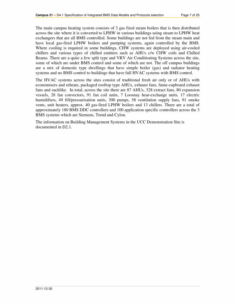
The main campus heating system consists of 3 gas fired steam boilers that is then distributed
across the site where it is converted to LPHW in various buildings using steam to LPHW heat
exchangers that are all BMS controlled. Some buildings are not fed from the steam main and
have local gas-fired LPHW boilers and pumping systems, again controlled by the BMS.
Where cooling is required in some buildings, CHW systems are deployed using air-cooled
chillers and various types of chilled emitters such as AHUs c/w CHW coils and Chilled
Beams. There are a quite a few split type and VRV Air Conditioning Systems across the site,
some of which are under BMS control and some of which are not. The off campus buildings
are a mix of domestic type dwellings that have simple boiler (gas) and radiator heating
systems and no BMS control to buildings that have full HVAC systems with BMS control.
The HVAC systems across the sites consist of traditional fresh air only or of AHUs with
economisers and reheats, packaged rooftop type AHUs, exhaust fans, fume-cupboard exhaust
fans and suchlike. In total, across the site there are 87 AHUs, 328 extract fans, 80 expansion
vessels, 28 fan convectors, 91 fan coil units, 7 Loosnay heat-exchange units, 17 electric
humidifiers, 49 fill/pressurisation units, 300 pumps, 58 ventilation supply fans, 91 smoke
vents, unit heaters, approx. 40 gas-fired LPHW boilers and 13 chillers. There are a total of
approximately 180 BMS DDC controllers and 100 application specific controllers across the 3
BMS systems which are Siemens, Trend and Cylon.
The information on Building Management Systems in the UCC Demonstration Site is
documented in D2.1.

Campus 21 ● D4.1 Specification of Integrated BMS Data Models and Protocols selection Page 8 of 25
2011-12-30
4. STATE OF THE ART: BUILDING PROTOCOLS AND
INFORMATION DATA MODELS
4.1 Building Protocol Standards
4.1.1 Building Automation and Control Network (BACnet)
“BACnet (Building Automation and Control Network) is a standardized data communication
protocol developed by ASHRAE for use in building automation to enable devices and
systems to exchange information.” [1] BACnet was developed to cover the need for a
standardized data communication protocol that would allow systems from various vendors,
such as HVAC, lighting, security and fire systems, to communicate with each other by
providing standardized methods for presenting, requesting, interpreting, and transporting
information, ensuring interoperability and manufacturer independence [1],[2].
Since the main goal of BACnet is to provide interoperability between devices such that
devices from different vendors or generations work together through the digital exchange
information. This is achieved by dividing the building automation functions in five
interoperability areas (IAs):
• Data Sharing
• Alarm and Event Management
• Scheduling
• Trending
• Device and Network Management
In building automation the distributed system can be depicted using a three layer model
(Management level, Automation level and Field level). Field level is responsible for
measurements, positioning and metering. Automation level is responsible for measurement,
control and regulation processes. Furthermore, monitoring, energy management and operation
management functions belong to Management level. “BACnet can be used at all levels of
building automation, but is particularly suited for management functions. As a result, is
preferably used as a superordinate system in larger installations with LonWorks and KNX
used in field level even though there is a BACnet implementation for the field level.” [1]
The protocol defines how and which messages can be transported from one device or system
to another. The different types of messages are the following:
• Binary input or output values
• Analog input or output values
• Software binary and analog input and output values
• Schedule information
• Alarm and event information
• Files
• Control logic
On the lower level communication layers (first and second layer according to OSI reference
model, ISO 7498), messages can be transported through Ethernet, MS/TP, LONTALK,
ARCNET or even Point-to-point connections over a telephone line. Wireless communication
is also possible through Wireless LAN (WLAN). On the network layer (third layer), the relay
of messages between similar or different networks is taken care off so devices communicate

Campus 21 ● D4.1 Specification of Integrated BMS Data Models and Protocols selection Page 9 of 25
2011-12-30
regardless of the lower layer technology used in these networks. “BACnet supports Internet
Protocol (IP) and therefore enables global networks to be interconnected (BACnet/IP). IP is a
network layer protocol and is responsible for routing packets through a complex network.” [1]
Above the network layer (in OSI model) is the transport layer. In this layer, BACnet uses
User Datagram Protocol (UDP), which belongs to the Internet Protocol family. UDP is a very
simple protocol that is used for transporting datagrams without acknowledgement or
guaranteed delivery. For this reason, the BACnet application layer is responsible for
controlling retransmission of a packet. Finally, the application layer is responsible for the
object types, services and procedures involved (these concepts are explained in the following
paragraphs) in any communication of a BACnet implementation.
BACnet devices store information, such as the temperature reading from a sensor or a control
command, in an object-oriented approach. Objects in BACnet are abstract data structures in
which information is stored as object properties. Objects have readable (R) and/or writeable
(W) properties which can be optional or mandatory for each object type. Developers are free
to define additional non-standard object types or properties if required.
For communication between devices, BACnet defines services that can be used to access
objects. Those services are divided into five groups:
• Object Access Services
• Alarm and Event Services
• Remote Device Management Services
• File Access Services
• Virtual Terminal Services
On the operator point of view now, “BACnet Operator Workstation (B-OWS) is the user
interface for the system. While it is primarily used for the operation of a system, the B-OWS
may also be used for configuration activities that are beyond the scope of BACnet standard.
The B-OWS is not intended for the direct digital control of systems” but it does enable some
functions in the five IAs defined above. “A B-OWS GUI, configuration and programming
tools and additional tools for integrating disparate networks vary depending on the
manufacturer. Unfortunately, there is no standardized development environment available (as
there is in other protocols). As a result, the practical use of BACnet is strongly influenced by
proprietary tools and, to a certain extent, limits the operation of components from different
manufacturers.” [1]
BACnet describes devices such as:
• Building Controller (B-BC) , which is a programmable automation device capable of
carrying out a variety of building automation and control tasks
• Advanced Application Controller (B-AAC), which is a control device with limited
resources compared to a B-BC, intended for specific applications that do not require
that much programming
• Application Specific Controller (B-ASC), which is a controller, programmed by the
manufacturer and the user can only change the parameters.
• Smart Actuators and Smart Sensors, which are simple devices that can communicate
using BACnet and then only send values as electrical signals upon request.
• Routers, which are responsible for interconnecting networks that have the same or
different network technology.
• Gateways to Other Systems allowing BACnet networks to connect with other
networks such as KNX and LONWORKS.
“Devices must conform precisely to the requirements of the BACnet standard. To show that a
device conforms to the protocol, the manufacturer must supply a Protocol Implementation
Conformance Statement (PICS) that identifies all the sections of BACnet that are
Campus 21 ● D4.1 Specification of Integrated BMS Data Models and Protocols selection Page 10 of 25
2011-12-30
implemented in the device.” [1] The BACnet Testing Laboratory (BTL) is an independent
institution to support compliance testing and interoperability testing for BACnet products.
“Once a product has passed all the tests it is awarded the BTL mark.” [1]
In order to integrate BACnet devices with the ICT world Gateway products are available
which translate between BACnet and BACnet/IP and BACnet/WS. Both allow common IT
systems and applications to access BACnet protocol data.
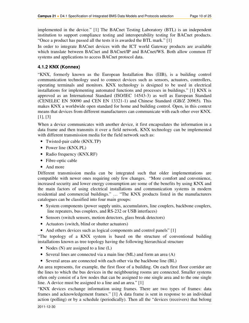
4.1.2 KNX (Konnex)
“KNX, formerly known as the European Installation Bus (EIB), is a building control
communication technology used to connect devices such as sensors, actuators, controllers,
operating terminals and monitors. KNX technology is designed to be used in electrical
installations for implementing automated functions and processes in buildings.” [1] KNX is
approved as an International Standard (ISO/IEC 14543-3) as well as European Standard
(CENELEC EN 50090 and CEN EN 13321-1) and Chinese Standard (GB/Z 20965). This
makes KNX a worldwide open standard for home and building control. Open, in this context
means that devices from different manufacturers can communicate with each other over KNX.
[1], [3]
When a device communicates with another device, it first encapsulates the information in a
data frame and then transmits it over a field network. KNX technology can be implemented
with different transmission media for the field network such as:
• Twisted-pair cable (KNX.TP)
• Power line (KNX.PL)
• Radio frequency (KNX.RF)
• Fibre-optic cable
• And more
Different transmission media can be integrated such that older implementations are
compatible with newer ones requiring only few changes. “More comfort and convenience,
increased security and lower energy consumption are some of the benefits by using KNX and
the main factors of using electrical installations and communication systems in modern
residential and commercial buildings.” … “The KNX products listed in the manufacturers
catalogues can be classified into four main groups:
• System components (power supply units, accumulators, line couplers, backbone couplers,
line repeaters, bus couplers, and RS-232 or USB interfaces)
• Sensors (switch sensors, motion detectors, glass break detectors)
• Actuators (switch, blind or shutter actuators)
• And others devices such as logical components and control panels” [1]
“The topology of a KNX system is based on the structure of conventional building
installations known as tree topology having the following hierarchical structure
• Nodes (N) are assigned to a line (L)
• Several lines are connected via a main line (ML) and form an area (A)
• Several areas are connected with each other via the backbone line (BL)
An area represents, for example, the first floor of a building. On each first floor corridor are
the lines to which the bus devices in the neighbouring rooms are connected. Smaller systems
often only consist of a few nodes that can be assigned to one single area and to the one single
line. A device must be assigned to a line and an area.” [1]
“KNX devices exchange information using frames. There are two types of frames: data
frames and acknowledgement frames.” [1] A data frame is sent in response to an individual
action (polling) or by a schedule (periodically). Then all the “devices (receivers) that belong

Campus 21 ● D4.1 Specification of Integrated BMS Data Models and Protocols selection Page 11 of 25
2011-12-30
to this group simultaneously confirm that they have received the data frame by returning an
acknowledgment frame. This frame is also called a summation frame, because it comprises
the confirmation frames from all the receivers. If the sender transmits a frame to a device
located on another line, the coupler confirms receipt of the frame.” ... “When a bus access
conflict occurs (two or more devices start sending data frames at the same time) KNX uses
the Carrier Sense Multiple Access/Collision Avoidance media access control protocol to
resolve this conflict, and to decide which device is allowed to send its frame first (bus
arbitration).” [1] In order to execute a function, the application program of at least one sensor
must exchange data (in the form of data frames) with the application program of at least one
actuator. To do this, the sending and receiving applications use a specific number of
communication objects. A communication object is an area of memory in a KNX device’s
microcontroller which is used for communicating with applications in other devices.
4.1.3 LonWorks
LonWorks is defined as a networking platform specifically created to address the needs of
control applications [1],[4],[5]. “LonWorks is an open networking solution for building
automation and control networks that was developed by the American company Echelon. It is
designed in such a way that it can be used in centralized building automation controllers as
well as in decentralized building control components. LonWorks is a standardized bus system
(ANSI/CEA-709.1-B and ISO/IEC DIS 14908) that enables intelligent devices to
communicate with each other over a locally operated control network (LON stands for Local
Operating Network).” [1]
“LON technology has become an integral part of building control. Distributing measurement,
monitoring and control functions among local, de-centrally installed components means that
you can customize a variety of comfort solutions for an individual room. For instance, there is
a wide range of sensors and actuators on the market for implementing the following functions:
• Heating, cooling and ventilating
• Lighting control
• Shade/blind control
• Security
• Multimedia” [1]
By using LON technology different devices can communicate allowing components to
interact in order to execute automated functions. For example a smoke detector could invoke
an air conditioning system to switch off and instruct windows to open to extract the smoke.
To sum up, using LON technology in building automation provides benefits such as:
• Comfort and convenience
• Efficiency through energy management functions
• Flexibility through the reprogramming options available
• Security
LonTalk is the protocol that defines how the LON devices are programmed for different
applications and how they communicate with each other as nodes in a network. Each network
device has a transceiver (short for transmitter and receiver). The transceiver provides a
physical communication interface between a LonWorks device and a LonWorks network.
There are specific transceivers for each medium such as:
• Twisted pair (most commonly used medium)
• Power line
• Radio frequency
• Fibre optics
Campus 21 ● D4.1 Specification of Integrated BMS Data Models and Protocols selection Page 12 of 25
2011-12-30
Interoperability, the ability of devices from different manufacturers to be able to exchange
information with each other, is extremely important so the LonMark Interoperability
Association [4] is responsible for defining a device’s basic functionality and minimum
requirements as well as the standard network variable types. Every device has an application
interface which is configured and customized by the manufacturers depending on the
functionality using the following functions for configuration:
• Bit input and output
• Byte input and output
• Serial input and output
• Slope input
• Period and pulse count input
• Frequency output
“In the LonTalk protocol, bus nodes (devices) that have equal access right to the transmission
channel use the predictive p-persistent Carrier Sense Multiple Access (CSMA) protocol to
communicate with each other.”[1] A physical connection between the LON nodes is a
prerequisite to communication. The LON nodes exchange the actual data using network
variables, a standardized way to represent data for interoperability. The LonMark
Interoperability Association has defined a set of rules so the different network variables could
be standardized (known as Standard Network Variable Types, SNVTs). “The following
definitions have been defined for the most commonly used variables:
• Area of application
• Name of the network variable type
• The variable’s configuration
• The total length in bytes
• Value range, degree of precision and units” [1]
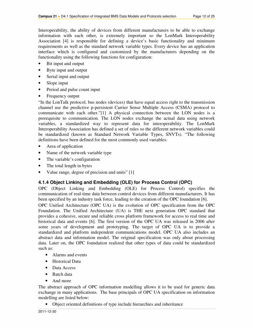
4.1.4 Object Linking and Embedding (OLE) for Process Control (OPC)
OPC (Object Linking and Embedding (OLE) for Process Control) specifies the
communication of real-time data between control devices from different manufacturers. It has
been specified by an industry task force, leading to the creation of the OPC foundation [6].
OPC Unified Architecture (OPC UA) is the evolution of OPC specification from the OPC
Foundation. The Unified Architecture (UA) is THE next generation OPC standard that
provides a cohesive, secure and reliable cross platform framework for access to real time and
historical data and events [6]. The first version of the OPC UA was released in 2006 after
some years of development and prototyping. The target of OPC UA is to provide a
standardized and platform independent communications model. OPC UA also includes an
abstract data and information model. The original specification was only about processing
data. Later on, the OPC foundation realized that other types of data could be standardized
such as:
• Alarms and events
• Historical Data
• Data Access
• Batch data
• And more
The abstract approach of OPC information modelling allows it to be used for generic data
exchange in many applications. The base principals of OPC UA specification on information
modelling are listed below:
• Object oriented definitions of type include hierarchies and inheritance

Campus 21 ● D4.1 Specification of Integrated BMS Data Models and Protocols selection Page 13 of 25
2011-12-30
• Type information can be accessed the same way as data.
• The same information can be presented in different ways, depending on usage and the
network nodes that require it. Full meshed network topology is also possible.
• The architecture is extensible in many ways, due to hierarchies and references between
nodes.
• The information model is adjustable to the current information model of any system.
• Server side modelling indicating less requirements from the clients
Interoperability is one of the main goals of OPC. Multi-vendor systems and devices must be
able to communicate and “understand” each other, and this is achieved by OPC certification
programs that include self-certification, interoperability workshops and 3rd
party testing by
independent interoperability certification test labs. A product can get two levels of OPC
certification, the “Self Tested” and the “Compliance Certified”. The “Self Tested” level is
granted by a process where OPC vendors verify the correct operation of their products by
passing a series of tests developed by the OPC foundation. On the other hand, “Compliance
Certified” level is granted by the Independent Certification Test Lab, where the staff of the
lab verify the correct operation of the products.
Data access is achieved by the OPC DA (Data Access) specification. OPC DA describes how
real-time data can be transferred between products without even knowing each other’s native
protocol. OPC DA is only used for real time values of data sources, for historical data access
(HDA) another specification is used (OPC HDA).
There are many advantages of using OPC UA, such as:
• Service oriented architecture for communication
• Interoperability (with Certification)
• Single solution for enterprise and embedded systems
• Improved security with a standard security model
• High performance communication protocols (Binary TCP based, SOAP/XML etc.)
• Reduced development cost (with existing OPC UA SDKs)
• Flexible object oriented information models
• Code reuse (with UA methods and programs)
Furthermore, today’s buildings have already a variety of building automation systems
implemented with different networking technologies. Therefore, interoperability between
devices using different technologies is also one important goal of OPC. OPC UA enables
mapping the information of many other existing protocols (for example BACnet) into the
OPC information model, and as a result this information can be accessed by OPC UA clients
in a standard and well defined way.
4.1.5 Open Building Information Xchange (oBIX)
“The scope of the oBIX (Open Building Information Xchange) TC is to develop a publicly
available web services interface specification that can be used to obtain data in a simple and
secure manner from HVAC, access control, utilities, and other building automation systems,
and to provide data exchange between facility systems and enterprise applications. In
addition, implementation guidelines are developed to facilitate the development of products
that use the web service interface [7]. The oBIX Committee has been created 2003 as the
CABA XML/Web Services Guideline Committee. Since then oBIX has been transferred to a
technical committee at the Organization for the Advancement of Structured Information
Standards (OASIS) [8].
As existing binary protocols like BACnet orLonTalk can be used over TCP/IP networks - they
have challenges with routers, firewalls, security, and compatibility with other network
Campus 21 ● D4.1 Specification of Integrated BMS Data Models and Protocols selection Page 14 of 25
2011-12-30
applications. There is an added challenge in that the industry is split between several largely
incompatible protocols. The oBIX committee claims, the integration of existing mostly non-
IP based protocols with access via Web Services [7]. Because oBIX integrates with the
enterprise, it aims to enable mechanical and electrical control systems to provide continuous
visibility of operational status and performance, flagging problems and trends for system
analysis or human attention.
4.1.6 IETF 6LoWPAN and IETF CoAP
IETF specified with 6LoWPAN [16] (”IPv6 over Low power Wireless Personal Area
Networks”) encapsulation and header compression mechanisms that allow IPv6 packets to be
sent to and received from IEEE 802.15.4 based networks. The motivation for this was to
enable resource constrained devices such as sensor nodes to reduce the IPv6 packet header
overhead. Together with the IETF Constrained Application Protocol (CoAP) specification it
will enable developers to realize RESTful communication paradigms using IPv6 on wireless
sensor devices. Note that at the time of writing, CoAP is still in an internet draft status.
Broadly speaking, CoAP is HTTP adapted for Machine-to-Machine communication patterns
using UDP as transport protocol – which implied on one hand that for reliable communication
a transaction mechanism needed to be added to CoAP but on the other hand allows unicast
and multicast message exchange.
4.2 Building Information Models
4.2.1 Standardized Solutions
4.2.1.1 Industry Foundation Classes (IFC)
The buildingSMART organization (International Alliance for Interoperability, IAI) developed
a common data schema in order to hold and exchange data between different proprietary
software applications [9]. The data schema comprises information covering the many
disciplines that contribute to a building throughout its lifecycle: from conception, through
design, construction and operation to refurbishment or demolition.
Industry Foundation Classes (IFC) are the main buildingSMART data model standard. The
IFC format is registered by ISO as ISO/PAS 16739 and is in the process of becoming an
official International Standard ISO/IS 16739 [10]. The IFC2x Platform Specification
provides an information model, written in EXPRESS (ISO 10303-11:1994), for sharing data
in the construction and facilities management industries. The IFC specification supports
different applications with the project life-cycle, such as architecture, building services
(HVAC - heating, ventilation, air conditioning, cooling, electrical), building automation,
facilities management and others. [10].
The IFC data model is an object oriented model that separates the object identifications and
the associated properties. It facilitates interoperability in the building industry, and is a
commonly used format for Building Information Modelling (BIM). IFC defines multiple file
formats, supporting various encodings of the same underlying data (IFC-SPF as text format
defined by ISO 10303-21, IFC-XML as XML format defined by ISO 10303-28, IFC-ZIP as
ZIP compressed format consisting of an embedded IFC-SPF file).
IFC defines an EXPRESS (data model language defined as ISO 10303-11 [11]) based entity-
relationship model consisting of several hundred entities organized into an object-based
inheritance hierarchy.

Campus 21 ● D4.1 Specification of Integrated BMS Data Models and Protocols selection Page 15 of 25
2011-12-30
4.2.1.2 Green Building XML (gbXML)
The Green Building XML schema, referred to as “gbXML”, was developed to facilitate a
common interoperability model integrating a myriad of design and development tools used in
the building industry [12]. The Green Building XML (gbXML) open schema aims to facilitate
the transfer of building properties stored in 3D building information models (BIM) to
engineering analysis tools. In addition, with the development of integration modules inside
major engineering analysis tools, gbXML has become the defacto industry standard schema.
Compared to IFC, gbXML has some limitations in geometry support. It is however easier and
more flexible to extend, while IFC are more comprehensive models, still with limited
complexity.
4.2.2 Proprietary Solutions
4.2.2.1 EU Project FIEMSER Data Model
The EU project FIEMSER objective is the development of an innovative energy management
system for existing and new residential buildings which pursues the increase of the efficiency
of the energy used and the reduction of the global energy demand of the building, but without
penalizing the comfort levels of the users [13],[14]. The FIEMSER consortium provided a
comprehensive study on available international standards (IAI/IFC, gbXML) as well as
approaches taken in a large number of European Research projects in ICT4EE for Buildings in
order to define a holistic data modelling for information exchange for home energy
management. Data cover information between the main components of the control platform,
to/from loads, generators and storages as well as external information (e.g. weather, pricing).
The modelling follows the bottom-up approach and is achieved by an UML class diagram
approach. The model defines 8 data categories which are described as independent sub-
models. These categories are environmental and contextual data, Energy-focussed BIM,
sensor network data, user preferences, resource scheduling, advices, energy performance
indicators and user access rights [14].
The D4.1 of the CAMPUS-21 project considers the results of the FIEMSER project for
evaluation of their Information Model, with possible consideration of extension for public
buildings and spaces.
4.2.2.2 Information Model for Data Aggregation proposed from TU Vienna
This subsection will point to a selective proprietary information model defined by a partner of
the CAMPUS-21 consortium. The Department of Building Physics and Building Ecology of
the Vienna University of Technology developed a multilayered architecture for concurrent
energy, performance, and occupancy data acquisition and processing in buildings. The aim is
to address the needs for a monitoring infrastructure necessary to measure and process all data
streams influencing building performance. Details about the proposed concept and evaluation
results can be found in [15].
The D4.1 of the CAMPUS-21 project may consider the evaluation of the proposed
Information Model for the monitoring layer during the architecture and system design phase.
The possible adaptation and extension will be discussed in the context of the final CAMPUS-
21 use cases.
Campus 21 ● D4.1 Specification of Integrated BMS Data Models and Protocols selection Page 16 of 25
2011-12-30
5. INTELLIGENT PROXY DESIGN
5.1 Layered High Level Proxy Design Architecture
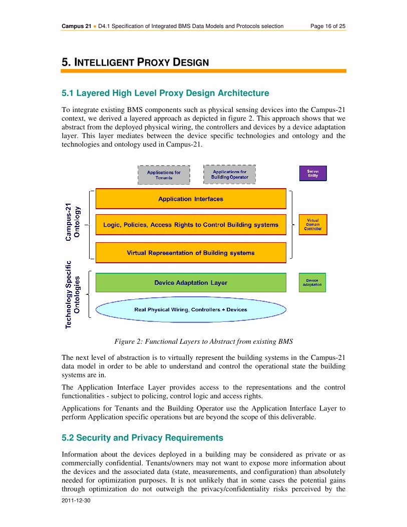
To integrate existing BMS components such as physical sensing devices into the Campus-21
context, we derived a layered approach as depicted in figure 2. This approach shows that we
abstract from the deployed physical wiring, the controllers and devices by a device adaptation
layer. This layer mediates between the device specific technologies and ontology and the
technologies and ontology used in Campus-21.
Figure 2: Functional Layers to Abstract from existing BMS
The next level of abstraction is to virtually represent the building systems in the Campus-21
data model in order to be able to understand and control the operational state the building
systems are in.
The Application Interface Layer provides access to the representations and the control
functionalities - subject to policing, control logic and access rights.
Applications for Tenants and the Building Operator use the Application Interface Layer to
perform Application specific operations but are beyond the scope of this deliverable.
5.2 Security and Privacy Requirements
Information about the devices deployed in a building may be considered as private or as
commercially confidential. Tenants/owners may not want to expose more information about
the devices and the associated data (state, measurements, and configuration) than absolutely
needed for optimization purposes. It is not unlikely that in some cases the potential gains
through optimization do not outweigh the privacy/confidentiality risks perceived by the

Campus 21 ● D4.1 Specification of Integrated BMS Data Models and Protocols selection Page 17 of 25
2011-12-30
users/customers/tenants. Individual measurements and device configurations can often be
aggregated into state information, e.g., about room conditions, and it seems that optimizations
could operate on aggregated information.
� R1 The design should pass only aggregated state information outside the building.
� R2 The design should support authentication and authorization of communicating entities.
� R3 The design should support confidentiality and integrity protection of exchanged data.
In case multiple tenants, e.g., different companies which potentially may be competing, are
located inside the same building, they may not want to expose their device data to the other
tenants. Then, data aggregation and protection as stated above may even be needed on the
different levels of hierarchy. This, in conjunction with above requirements, implies that higher
hierarchy levels may aggregate states even more in order to protect state information of lower
hierarchy levels.
� R4 The proxy shall support aggregation of state information where the low level data shall
be aggregated at higher levels to ensure data privacy.
� R5 The design should pass only aggregated state information between different levels of
hierarchy inside the building. In case components of the same level of the hierarchy
communicate among each other, the same applies.
It may be necessary in some cases that optimization operations need to be informed of lower
level state information or of information on individual devices. In this case, the higher
hierarchy level may query additional information from the lower level. However, the lower
level may choose to deny the request.
� R6 Higher hierarchy levels should be able to request more detailed information about
states or device data. In case components of the same level of the hierarchy communicate
among each other, the same applies.
� R7 Lower hierarchy levels should be able to deny requests for more detailed information
from higher hierarchy levels. In case components of the same level of the hierarchy
communicate among each other, the same applies.
If optimization operations work on aggregated state information instead of low level device
data, it is implied that recommendations resulting from the optimization operations are
concerned about aggregated information state changes instead of actuator actions. Following
this line of thought, lower hierarchy levels need to translate recommendations into
instructions for specific devices. It may be necessary that recommendations are translated in
multiple hierarchy levels prior to being device specific instructions.
� R8 Recommendations represent suggestions of actions to change aggregate state
information.
� R9 A hierarchy level should translate received recommendations into recommendations
applicable to the next lower level or into instructions for individual devices associated to the
hierarchy level.
Recommendations may conflict with tenants’ interests. Therefore the operator of the
respective level impacted by a recommendation should be asked for confirmation before
implementing the actions associated with the recommendations by appropriate means, e.g., a
GUI.
� R10 Operators of systems impacted associated to their hierarchy level should be asked for
confirmation before implementing the actions associated with the recommendations by
appropriate means. Note that however, not all recommendations should be confirmed as that
would cause too much “noise”.

Campus 21 ● D4.1 Specification of Integrated BMS Data Models and Protocols selection Page 18 of 25
2011-12-30
� R11 Recommendations, decisions, states should be logged.
5.3 Intelligent Proxy Functional Architecture
Figure 3 depicts the proxy design architecture we envisage to abstract from existing, real
physical devices on the left side. These devices are connected typically using communication
protocols such as BACnet, LON or KNX. In figure 3 we assume that a translation gateway
from the device protocols to IP exists, however our architecture can as well deal with non-IP
protocols. For this great degree of flexibility and protocol independence, we introduced the
Device Adaptation functional block (green). This block corresponds to the Device Adaptation
Layer in figure 2 and maps the device layer specific representations into the integrated data
model we use to abstract from the real world devices. Recommendations for integrated
Protocol and Data Model are provided in section 6.
Figure 3: Proxy design to abstract from existing BMS for Campus-21
Our intelligent proxy design then shows in figure 3 the virtual domain controller (VDC,
yellow) component. This controller is responsible for an associated virtual domain. Each
virtual domain is a logical association of devices that can be defined in a very flexible way
and may be used to represent, e.g., the heating system of an entire building, an entire single
floor or even an individual room – depending on the specific context and setting the Campus-
21 proxy architecture is used in. Virtual domains can be hierarchically structured so that, e.g.,
multiple virtual domains, each representing an individual floor, can be grouped into one
virtual domain for the entire building. This is represented in figure 3 by the VDC Head. Our
approach is not limited to two layers of hierarchy but is virtually unlimited. The highest
hierarchy layer VDC interacts with the so called “Server Entity” which takes care of the
situation on a bigger picture, e.g., for large scale optimizations, distribution grid load
balancing or building health problem solving.

Campus 21 ● D4.1 Specification of Integrated BMS Data Models and Protocols selection Page 19 of 25
2011-12-30
Based on the mandatory and optional requirements in section 5.2, we assign different
responsibilities and tasks to the VDC components depicted in figure 3. We differentiate
between a centralized, a decentralized approach and an evolutionary approach.
5.3.1 Centralized Approach
In the centralized approach, all control and optimization decisions are taken at the server
entity. To address the security concerns listed in section 5.2, state aggregation is performed at
the different hierarchy level VDCs. Each VDC translates recommendations received from a
higher hierarchy level (higher level VDC or the Server entity) into recommendations to be
passed to a lower hierarchy level VDC or into instructions for specific devices, depending on
the VDC’s hierarchy level.
We believe that this approach needs a large amount of communication between architecture
components to take optimization decisions and is also introducing a single point of failure (the
Server entity).
However, due to the fact that optimization decisions may span more than one building this
approach can optimize energy usage on a larger scale than individual hierarchy levels.
We believe that the state aggregation promoted in section 5.2 does not reduce the optimization
potential as we allow for querying additional information from individual devices.
5.3.2 Decentralized Approach
In this approach, VDCs try to decide on local actions on their own as much as possible,
potentially in collaboration with the operator. However, depending on the domain definition
(e.g., as listed in 5.3 where one VDC may monitor and control a single system and another is
responsible for monitoring room temperatures), some optimization decisions need to be taken
at a higher hierarchy level or even outside the building at a central optimization component
(the server entity in figure 3). Each VDC translates recommendations received from a higher
hierarchy level (higher level VDC or the Server entity) into recommendations to be passed to
a lower hierarchy level VDC or into instructions for specific devices, depending on the
VDC’s hierarchy level.
This approach also addresses the security concerns listed in section 5.2 by aggregating state
information in the different hierarchy level VDCs.
We believe that this approach reduces the amount of communication needed between
architecture components and also adds resilience against the single point of failure (the Server
entity). However, optimization decisions might be less than optimal as the bigger picture of
the server entity might be missing. Also the complexity of the control logic in the VDC might
be high.
Mixtures between the centralized and the decentralized approaches are possible. As an
example the proposed architecture can realize a deployment where the VDC Head is the only
component that centrally takes most decisions for a particular building and the lower
hierarchy level VDCs act as in the centralized approach. The server entity is then involved for
large scale optimizations only. This should avoid overload situations for the server entity and
still allows for a holistic (across different in-building systems) optimization of building
energy usage, per building.
5.3.3 Evolutionary Approach
This approach is a mixture between the centralized and the decentralized approach. At first,
all decisions are taken at the Server entity as described in section 5.3.1. Each VDC translates
recommendations received from a higher hierarchy level (higher level VDC or the Server
Campus 21 ● D4.1 Specification of Integrated BMS Data Models and Protocols selection Page 20 of 25
2011-12-30
entity into recommendations to be passed to a lower hierarchy level VDC or into instructions
for specific devices, depending on the VDCs’ hierarchy level. However, received
recommendations and state data are stored. If, after some learning time, identical
recommendations are received for similar system state information, the system will start
taking decisions according to the recorded recommendations and effectively take a local
decision as described in 5.3.2.
This approach also addresses the security concerns listed in section 5.2 by aggregating state
information in the different hierarchy level VDCs.
We believe that this approach combines benefits from both approaches: It applies learning
techniques and thus reduces, after some learning time, the amount of communication needed
between architecture components and also adds resilience against the single point of failure
(the Server entity). We believe that the optimization decisions might be close to the
centralized approach as in the beginning always the server entity is being contacted.
Moreover, the control logic of the VDC might be reduced to matching the current aggregated
state data to past states, and if there is a match re-implement the recommendations received in
the past.
Similar considerations on mixing the approaches as in section 5.3.2 apply. In the evolutionary
approach, e.g., the proposed architecture can realize a deployment where only the VDC Head
component centrally tries to apply learning techniques and the lower hierarchy level VDCs act
as in the centralized approach. The server entity is then involved at the beginning in all
optimization decisions and will then be gradually involved only for large scale optimizations
or for unknown building aggregated states.
Campus 21 ● D4.1 Specification of Integrated BMS Data Models and Protocols selection Page 21 of 25
2011-12-30
6. PREFERENCES FOR CAMPUS-21 INTEGRATED
PROTOCOL AND DATA MODEL
6.1 Integrated Data Model considerations
The CAMPUS-21 system architecture will support the aggregation of monitoring data as well
as the provisioning of control request. Data aggregation as well controlling and
recommendations will be supported in centralized as well as de-centralized manner.
When looking at the available standards for Information Models, there are the IFC and
gbXML as the mostly used models in the industry. Research projects still show in the
evaluations (see [13]), that for specific application domains the interpretation of the models
might lead to extensions or adaptations.
As result of the discussions in CAMPUS-21 WP4 in task 4.1, the recommendation is given to
follow the most used industry standard IFC and aim to provide respective extensions
applicable for public buildings and spaces if needed. As an alternative, the FIEMSER data
model may be considered.
Depending on particular demonstration scenarios, potentially also simpler, device dependent
data models may be sufficient. However, from a holistic architecture viewpoint, a higher level
of abstraction is desirable to facilitate algorithmic implementation, code reuse and generic
applicability of the system.
6.2 Integrated Protocol considerations
Depending on the information model chosen for CAMPUS-21 WP4 to represent the holistic
system, exact mappings to state of the art protocols will need to be defined. As such, it is in
principle possible to use well structured, extensible ICT protocols such as SOAP to carry data
within the CAMPUS-21 system.
However, OPC UA and BACnet/WS can be recognized as standards applicable for the
monitoring and control decision systems of building automation. Relying on these protocols
enables access to a wide range of sensing and control hardware e.g. by relying on Gateway
products towards the major building protocol standards. The discussions in CAMPUS-21
WP4 in task 4.1 lead to the recommendation, as these gateways typically communicate device
specific data, to map the device specific data into the integrated data model recommended in
the previous section.
Summing up, OPC UA with its extension to SOA-based design and object-oriented (node-
based) information model and BACnet/WS are currently recommended as two of the options
for the detailed system protocol design discussion handed over to the work in task 4.2.
Campus 21 ● D4.1 Specification of Integrated BMS Data Models and Protocols selection Page 22 of 25
2011-12-30
7. CONCLUSIONS
7.1 Contribution to overall picture
Deliverable D4.1 is providing
• State-of-the-Art overview of existing data communication protocols strongly related to
the existing infrastructures at the planned CAMPUS-21 demo sites (see deliverable
D2.1 for details). Deliverable D4.1 recommends for the usage of a harmonized
protocol and standardized information model for consideration of the CAMPUS-21
system design, integrating over the planned performance enhancements.
• Based on the complexity of the integrative approach, security requirements addressing
the interaction between components in the trusted domain, as well as between trusted
and non-trusted domains are defined. These requirements also cover privacy concerns.
• The proxy design for the distributed CAMPUS-21 data acquisition and control system
is proposed. It will accomplish the transfer from the BMS subsystems’ specific
communications realized over e.g. BACnet or LonWorks towards an abstract data
layer with a common communication protocol.
7.2 Relation to the state-of-the-art and progress beyond it
Deliverable D4.1 extends beyond existing BMS practise by:
• Addressing the given protocol diversity for the demo sites and in the industry in
general, the deliverable D2.1 is recommending a harmonized protocol for an abstract
data layer for consideration of the CAMPUS-21 system design.
• Compared to the currently uncoordinated independent BMS subsystems, the proposed
proxy design based on a hierarchical structure and its distributed virtual domain
controllers enables a coordinated data aggregation across the BMS subsystem
monitoring enhanced with additional sensor information. Also, the design introduces a
supervisory-styled control and recommendation process.
• The proposed proxy design builds on free-designable virtual domains which allows for
a high flexibility in the holistic energy management adapting to different performance
metrics (e.g. related to building architecture, energy systems, usage pattern type, etc.).
7.3 Impacts to other WPs and Tasks
Deliverable D4.1 directly impacts:
• Architecture and detailed system design which will be defined in WP4 Task4.2.
• Energy Management Logic and control algorithms using sensor and building data
(historical, near-time operational) which will be defined in WP5 and WP6
Adaptations to the developed approach are expected from the results of WP2 Task 2.2, which
will define the performance metrics and may propose enhancements to the monitoring and
control infrastructure of the different demonstration sites.

Campus 21 ● D4.1 Specification of Integrated BMS Data Models and Protocols selection Page 23 of 25
2011-12-30
8. ABBREVIATIONS
ASHRAE American Society of Heating, Refrigerating and Air-Conditioning Engineers
BACnet Building Automation and Control Network
BIM Building Information Model
DDC Direct digital controllers
FIEMSER Friendly Intelligent Energy Management System for Existing Residential
Buildings (EU Project)
gbXML Green Building XML
IAI International Alliance for Interoperability
IFC Industry Foundation Classes
KNX Konnex
LonWorks Local Operating Network
oBIX Open Building Information Xchange
OLE Object Linking and Embedding
OPC OLE for Process Control
XML eXtensible Markup Language

Campus 21 ● D4.1 Specification of Integrated BMS Data Models and Protocols selection Page 24 of 25
2011-12-30
9. REFERENCES
[1] H. Merz, T. Hansemann, C. Hübner, Building Automation Communication
systems with EIB/KNX, LON and BACnet (Signals and Communication
Technology), Springer 2009.
[2] BACnet - Official Website of ASHRAE SSPC 135, http://www.bacnet.org/
[3] Konnex– Official website of KNX Association , http://www.knx.org/
[4] Echelon - LonWorks Platform for Control Networking
http://www.echelon.com/products/lonworks_control_networking.htm
[5] LonMark International, http://www.lonmark.org/
[6] OPC Foundation, http://www.opcfoundation.org/
[7] oBIX –Open Building Information Exchange, http://www.obix.org/
[8] OASIS Open Building Information Exchange (oBIX) TC, http://www.oasis-
open.org/committees/tc_home.php?wg_abbrev=obix
[9] BuildingSmart Organization – international home of Open BIM,
http://www.buildingsmart.com
[10] ISO/PAS 16739:2005 - Industry Foundation Classes, Release 2x, Platform
Specification (IFC2x Platform), http://www.iso.org/
[11] ISO International Standard 10303-11:1994, Industrial automation systems and
integration — Product data representation andexchange — Part 11: Description
methods: The EXPRESS language reference manual, International Organization
for Standardization, http://www.iso.org/, Geneva, Switzerland (1994).
[12] Green Building XML (gbXML) Schema: a Building Information Model
Solution for Our Green World, http://www.gbxml.org/
[13] FIEMSER - Energy & behavioural modelling for managing energy resources in
residential buildings, 2nd Workshop on eeBuildings Data Models, Sophia-
Antipolis, October 2010
[14] EU FIEMSER (Grant agreement no.: 248605), http://www.fiemser.eu/
[15] R. Zach et al., An integrated architecture for energy systems and indoor climate
monitoring in buildings, 7. Internationale Energiewirtschaftstagung (IETW),
Vienna 2011
[16] RFC 4944, IETF 6LoWPAN, http://tools.ietf.org/html/rfc4944