deliverable 4 - salus 4.3 dissemination level: public page 2 of 55 authors ... tomorrow be part of...
TRANSCRIPT
Security And InteroperabiLity in Next Generation PPDR CommUnication InfrastructureS
Project Number: 313296
Deliverable 4.3 Business Analysis – Intermediate
Scope Scheduled deliverable
Lead Beneficiary Alcatel-Lucent International
Dissemination level Public
Document creation date 21/Nov/2014
Document release date 19/Mar/2015
Contractual Date of Delivery 28/Feb/2015
Version 1.3
Status Released
Abstract: Deliverable 4.3 is focus on the business analysis of next generation PPDR networks detailing the different models with techno-economical analysis. Possible roadmaps are also provided. It is to be noted that this document is an Intermediate version.

Deliverable 4.3 Dissemination level: Public Page 2 of 55
AUTHORS
Name Organisation Email
Jérôme Brouet ALU-I [email protected]
Bert Bouwers ROH [email protected]
Frank Brouwer FIGO [email protected]
Panagiotis Galiotos UPAT [email protected]
Georgios Charalampopoulos UPAT [email protected]
Theofilos Chrysikos UPAT [email protected]
Daniel Zerbib CAS [email protected]
Peter Wickson AW [email protected]
QUALITY ASSURANCE TEAM
Name Organisation Email
Daniel Zerbib CAS [email protected]
Peter Wickson AW [email protected]
Yevgeni Koucheryavy UBITEL [email protected]

Deliverable 4.3 Dissemination level: Public Page 3 of 55
EXECUTIVE SUMMARY
The benefits of broadband capabilities for PPDR users and for the European community is a given. Broadband applications and services will enhance the operational effectiveness of PPDR users. Indeed, broadband PPDR systems will enhance situational awareness (voice, data, video, pictures, sensors...) that will in turn lead to better and timely decisions while improving safety for citizens and PPDR personal. However, the transition to broadband is not an easy path for PPDR organisations. The challenges that will be faced by PPDR organisations moving to broadband will be technical, cultural, operational, regulatory and economical. The intermediate version of the SALUS business analysis covers the following aspects:
Existing and emerging technologies roadmap for PPDR - This section focuses mainly on
a status of Public Safety LTE standardisation features that would be available (as of
today) by early 2016 on paper. This section also gives a regulatory status of dedicated
spectrum for broadband PPDR. Major outcome on the topic are expected in upcoming
World Radio Conference in November 2015 and will be reflected in the final version of
the deliverable.
Business models – These cover four main classes of models such as commercial MNO,
dedicated networks, systems on wheels and a hybrid model. The qualitative analysis
provided in this deliverable leads to the conclusion that the hybrid model is probably the
best one. Merits of these models will be further analysed in the final version of the
deliverable with quantitative analysis using the SALUS Techno Economical tool.
Possible roadmap migration to LTE – This describes possible preliminary roadmaps
covering multiple options for early and late adopters with or without dedicated spectrum.
Main conclusions are that migration to full LTE PPDR network may happen between 5
years (early adopters) to 15-20 years (late adopters). This section will be further
augmented in the final version of the business analysis deliverable in the light of the
enhanced analysis of the technical and business models sections.
It is to be noted that the final version of the deliverable is planned for February 2016.

Deliverable 4.3 Dissemination level: Public Page 4 of 55
TABLE OF CONTENTS
EXECUTIVE SUMMARY ............................................................................................................ 3
TABLE OF CONTENTS ............................................................................................................. 4
TABLE OF FIGURES ................................................................................................................. 5
1 Introduction ......................................................................................................................... 6
2 Current picture and technology perspective ......................................................................... 7
2.1 TETRA system ............................................................................................................. 7
2.1.1 Introduction to TETRA ........................................................................................... 7
2.1.2 Market segments ................................................................................................... 7
2.1.3 Spectrum ............................................................................................................... 8
2.1.4 Evolution & Longevity ............................................................................................ 9
2.1.5 Perspective on TETRA networks for PPDR in Europe ........................................... 9
2.2 TETRAPOL system .................................................................................................... 11
2.2.1 The current picture .............................................................................................. 11
2.2.2 Operational trends ............................................................................................... 11
2.2.3 Converged solution ............................................................................................. 12
2.3 LTE systems .............................................................................................................. 12
2.3.1 LTE is the global 4G cellular system ................................................................... 12
2.3.2 LTE for PPDR users – Technology roadmap ....................................................... 13
2.3.3 Spectrum for PPDR ............................................................................................. 16
2.4 Wi-Fi Systems ............................................................................................................ 17
2.4.1 Infrastructure mode ............................................................................................. 17
2.4.2 Ad-hoc mode ....................................................................................................... 18
3 Possible Future mode of operations .................................................................................. 21
3.1 Description of different possible models ..................................................................... 21
3.1.1 Broadband services from Mobile Network Operators........................................... 21
3.1.2 Broadband services from dedicated networks ..................................................... 31
3.1.3 Systems on wheels ............................................................................................. 36
3.1.4 Hybrid models ..................................................................................................... 41
3.2 Merits of the possible models ..................................................................................... 41
4 Possible migration scenarios and roadmap ....................................................................... 44
4.1 Roadmap for “early” adopters ..................................................................................... 44
4.2 Roadmap for “late” adopters ....................................................................................... 48
5 Conclusions ....................................................................................................................... 50
References ............................................................................................................................... 51
Acronyms ................................................................................................................................. 54

Deliverable 4.3 Dissemination level: Public Page 5 of 55
TABLE OF FIGURES
Figure 1 - Installed TETRA systems per market segment ........................................................... 8 Figure 2 - Commercial LTE networks worldwide ....................................................................... 12 Figure 3 - Example of new capabilities for PDDR users with LTE ............................................. 14 Figure 4 - Mission-Critical LTE features .................................................................................... 15 Figure 5 - Wi-Fi Hot-Spots by venue type 2013-2018 [14] ........................................................ 17 Figure 6 - High level architecture of the MNO model ................................................................ 22 Figure 7 - Example of recurring cost for one year (Y=1) and cumulated over 10 years (Y = 1 to 10) as a function of the PPDR subscribers [assumptions, unlimited data plan at 20€ / month subscription fee with 5% yearly discount] ................................................................................. 24 Figure 8 - High level simplified architecture for light PPDR MVNO ........................................... 25 Figure 9 - Simplified High Level Full PPDR MVNO architecture ............................................... 26 Figure 10 - 4G penetration in the member states in 2013 ([26]) ................................................ 29 Figure 11 - 4G coverage in France, July 2014 ([27]) ................................................................. 29 Figure 12 - UK 4G mobile network coverage, June 2014 ([28]) ................................................ 30 Figure 13 - Carrier Hampton ..................................................................................................... 31 Figure 14 - Dedicated LTE network (simplified) ........................................................................ 32 Figure 15 -IDEA framework ...................................................................................................... 35 Figure 16 - Identified and Sustainable Public WLAN Business Models ..................................... 36 Figure 17 - Simplified high level architecture of MN – CCE ...................................................... 39 Figure 18 - Simplified high level architecture of MN – DR ......................................................... 40 Figure 19 - Example of roadmap for early adopter and dedicated frequency below 1 GHz ....... 46 Figure 20 - Example of roadmap for early adopter and dedicated frequency above 1 GHz ...... 47 Figure 21 - Example of roadmap for early adopter without dedicated broadband frequency ..... 47 Figure 22 - Example of roadmap for late adopter and dedicated frequency below 1 GHz ......... 48 Figure 23 - Example of roadmap for late adopter without dedicated broadband frequency ....... 49

Deliverable 4.3 Dissemination level: Public Page 6 of 55
1 INTRODUCTION
The benefits of broadband capabilities for PPDR users and for the European community is a given. Broadband applications and services will enhance the operational effectiveness of PPDR users. Indeed, broadband PPDR systems will enhance situational awareness (voice, data, video, pictures, sensors...) that will in turn lead to better and timely decisions while improving safety for citizens and PPDR personal. Besides, broadband PPDR systems will enable automated and remote mobile office duties that will increase presence time of PPDR user on field (the use of broadband in UK proved to increase by 30 minutes per shift per staff the time spent policing in the community [1]). The enhanced effectiveness translates in real life into faster time to resolve crimes, better efficiency in rescuing / saving lives... which also translates into an economical benefit to the society. A recent report from London School of Economics evaluated that broadband for PPDR users could bring a socio-economical benefit around 34 b€ per year across the 28 member states of the European Union [1]. However, the transition to broadband is not an easy path for PPDR organisations. Multiple hurdles are under the way such as:
Economical: deploying a new system with regional / nationwide footprint requires
significant investments that need to be secured and planned ahead, a difficult task in
current constrained budget and economy across Europe.
Regulatory: deploying a broadband system requires substantial amount of (dedicated)
spectrum and although some options are being worked out right now at CEPT level, it is
still to be seen if broadband spectrum will be allocated to PPDR in all member states in
the short to mid-term,
Technical: Commercial off the shelf (COTS) technologies may not offer today all the
desired functionality to turn them into a mission critical system (features, security,
scalability, etc). 3GPP and SALUS will contribute towards this goal but they are still a
few years away. Besides, deploying and managing a new system based on a new
technology will require additional skill set very different from the one available in PPDR
organisations today,
Change management: new capabilities will lead to new applications and usage that will
impact operational procedures. Intensive training of the PPDR users will be critical to
reach full benefits of those new capabilities but also to demonstrate the operational
enhancements to get massive adoption from the end-users.
This deliverable explores and discusses the possible ways to evolve from present mode of operations (using specialised narrowband system such as TETRA or TETRAPOL) to future mode of operations based on broadband systems. In section 2, the document describes the current picture and the expected evolution of the key systems that are present today and will tomorrow be part of the PPDR systems (TETRA, TETRAPOL, LTE, Wi-Fi). In particular, the roadmap of the public safety related features from the LTE standard and the regulation status are presented. In section 3, the different business models bringing broadband capabilities to PPDR users (based on dedicated and/or commercial based 4G networks) are given and their respective merits are discussed. Section 4 highlights possible migration roadmap scenarios and are followed by some concluding remarks. It is to be noted that this deliverable is an intermediate deliverable. The final version will include updates on the standardisation and regulatory front (e.g. taking into account the outcome of WRC-15 on spectrum for PPDR if any, discussing 5G) and will refine the business model options (including e.g. more details on the inclusion of Wi-Fi) and the migration roadmap scenarios with numerical examples based on the SALUS Techno-Economical Tool [2].

Deliverable 4.3 Dissemination level: Public Page 7 of 55
2 CURRENT PICTURE AND TECHNOLOGY PERSPECTIVE
This section describes for each technology that will be used in future PPDR networks (TETRA, TETRAPOL, LTE and Wi-Fi), their level of maturity (mainly around standard, deployments and spectrum) to handle PPDR services, their expected evolution path, roadmap and lifecycle.
2.1 TETRA system
2.1.1 Introduction to TETRA Note: this section is based on information from the TCCA web site [3]. TETRA is an open standard developed by the European Telecommunications Standards Institute (ETSI). The main purpose of the TETRA standard was to define a series of open interfaces, as well as services and facilities, in sufficient details to enable independent manufacturers to develop infrastructure and terminal products that would fully interoperate with each other as well as meet the needs of traditional Private Mobile Radio (PMR) user organisations. The initial responsibility of ETSI Project TETRA (now known as ETSI Technical Committee TETRA, TC TETRA) was to deliver a set of standards, under a mandate from the European Commission, for a Digital Trunked PMR communications system that could be deployed in Western Europe. As well as producing these mandatory ETSI deliverables (now completed), TC TETRA's responsibility was, and still is, to make sure that the portfolio of standards continue to be developed in accordance with end-user needs and priorities. The technology solutions chosen to meet user requirements contained in the TETRA standards have been, and continue to be, developed primarily by well-known and respected manufacturers who have been serving the PMR market with products and services for several decades. This combined "Know How" ensures that optimum technology solutions are chosen to meet user requirements. Although the prime responsibility of ETSI is to develop standards for Europe, many of its standards are also adopted world-wide, as evidenced by the uptake of GSM, the first digital wireless technology standard developed by ETSI. Similarly, the TETRA standard has also become a truly global standard with deployments in all continents of the world, including the US where the Federal Communications Commission (FCC) has recently (2011) granted approval for products conforming to TETRA standard to be available there for business, industrial and transport sectors. It is also to be noted that actual multi-vendor interworking mainly applies at the air interface level. The interface between the TETRA base stations and TETRA switch is proprietary as well as the interface to the dispatcher stations. Consequently, PPDR organisations are using single source supplier TETRA solutions for the infrastructure but can benefit from different vendors for the terminals. Also, TETRA systems from different vendors are usually not interoperable (although a specification for Inter System Interworking ISI exists), which make cross border operations difficult even when two neighbouring countries are using TETRA systems.
2.1.2 Market segments The largest market for TETRA solutions is that of public safety and government, where the trend is for the deployment of nationwide TETRA networks shared by all public safety organisations for reasons of economics (sharing), autonomy of operation for routine communications and the ability to fully interoperate with other organisations during emergency situations and disasters.

Deliverable 4.3 Dissemination level: Public Page 8 of 55
The transportation market is the next fastest growing market, especially for Mass Rapid Transport systems and major Airports. Interestingly, TETRA is also used by the military for non-tactical operations, a market application not originally anticipated for TETRA. Because TETRA has been specifically developed to serve traditional PMR users and is optimised for medium to high capacity applications by utilising Time Division Multiple Access (TDMA) technology, TETRA is also used for Public Access Mobile Radio (PAMR) applications. Other market segments that are served by TETRA solutions include Utilities, Oil and Gas, as well as Business and Industry. Figure 1 shows the current division of TETRA market segments as of 2014 [4].
Figure 1 - Installed TETRA systems per market segment
Some other key figures on TETRA deployments include:
Currently, over 3,150,000 critical communication professionals now use TETRA radios;
Almost 600,000 new and replacement TETRA terminals were shipped in 2013;
Upward trend continuing with over 4,000,000 active terminals by 2017;
The TETRA infrastructure and System integration market is projected to be worth over
€600 million in 2014;
Services associated with the implementation and maintenance of TETRA infrastructure
are expected to increase to nearly €180 million in 2014.
The TETRA infrastructure market is projected to grow at 7-8% between 2013 and 2014. The success and market uptake of TETRA has also created a strong base of application developers who are able to provide a wide variety of applications for use with TETRA.
2.1.3 Spectrum TETRA is a narrowband TDMA based digital radio technology that uses 25 kHz channels. Due to the stringent requirement on adjacent channel power and wideband noise, TETRA systems can be allocated channels side-by-side with analogue radio networks. Table 1 gives the different options for spectrum around the world. It is to be noted that across Europe the band 380-385 MHz paired with 390-395 MHz is the harmonised band for PPDR narrow-band systems. Out of this range, most frequencies are used for trunked mode operations (TMO) but a set of channels are reserved for direct mode operations (DMO) and air-ground-air (AGA).
Deliverable 4.3 Dissemination level: Public Page 9 of 55
Frequency band Duplex spacing Market
300 – 350 MHz 10 or 36 MHz Russia
350 – 370 MHz 10 MHz China
380 – 400 MHz 10 MHz Europe, Asia, South America (Public Safety)
410 – 430 MHz 10 MHz Europe, US (commercial)
450 – 500 MHz 10 MHz Europe, US, South America, Australia (commercial)
805-870 MHz 45 MHz US, Asia, South America (commercial)
Table 1 - Worldwide spectrum availability for TETRA
2.1.4 Evolution & Longevity The ETSI TETRA standard will continue to evolve beyond Release 1 and Release 2 to provide additional enhancements as driven by user needs, technology innovations and other parallel standard developments. As a consequence, ETSI has no plans to develop a new technology standard for use by large traditional PMR user organisations. Similarly, other technology standards being developed and/or available outside Europe offer little or no benefit over what TETRA already provides. This planned evolution of TETRA can be appreciated when considering that traditional PMR user organisations will always require private PMR networks because public networks cannot adequately provide the required RF coverage, Grade of Service (GoS) during busy periods, resilience and high levels of reliability. Besides these basic needs, public networks will probably not be able to provide the specialised voice services such as wide area fast call-set up all for group calls, DMO and high levels of secure encryption for voice and data. A standardised capability will be available in the mid-term but it is less certain if commercial operators would implement them unless they have a contract with an organisation requiring such specialist features. In summary, TETRA will evolve in a similar way to GSM, which evolved from providing a basic V+D "one to one" telephony service (via GSM II+, GPRS, EDGE, etc.) to UMTS/3G supporting powerful multimedia applications and High Speed Data. Also, the focus and technology solution for Next Generation Mobile Networks (NGMN) will primarily be for public networks. Taking these previous factors into consideration and the fact that analogue MPT 1327 trunking networks are still being deployed across the world more than 28 years after the technology was first developed, TETRA networks are expected to be available for at least another 15 years, thereby ensuring a very good return on investment for user organisations as well as manufacturers and suppliers.
2.1.5 Perspective on TETRA networks for PPDR in Europe TETRA remains the standard-of-choice for mission critical voice and data for European PPDR organisations. Although some countries (most notably the UK) are pursuing LTE as the next step of evolution for mission-critical voice and data in the short term, most governments still expect to rely on TETRA for PPDR applications during the next 5 to 15 years. This is confirmed by recent uptake of projects for new TETRA networks (such as in Germany where the TETRA network deployment is close to being completed and Poland that will start this year) as well as replacement and upgrades of existing TETRA networks by new TETRA networks, like in The Netherlands and in Belgium.

Deliverable 4.3 Dissemination level: Public Page 10 of 55
Note that a mid-life upgrade of TETRA networks is also expected in many more countries, especially if first or second generation TETRA networks were supplied in the 2000-2008 period. New IP-based networks offer many benefits to the PPDR operator and users, including continuous support, lower operating cost and advanced functionality. Table 2 provides a reference to the status of countrywide TETRA networks for PPDR within Europe based on intelligence gathered from multiple sources on the Internet.
Country Network Supplier
(Infrastructure) Base
stations Terminals Operation
Andorra STA Rohill 30 1,500 2008 - 2025
Austria TETRON Motorola 1,300 22,000
Belgium ASTRID Airbus DS 500 56,000 2000 - 2025
Denmark SINE Motorola 500 15,000 2007 - 2025
Finland VIRVE Airbus DS 1,350 55,000
Germany BOSNET Airbus DS 4,500 200,000 2008 - 2025
Greece OTE Motorola
Hungary Pro-M Airbus DS 300
Iceland TETRA Iceland Motorola 150
Ireland TETRA Ireland Motorola 600
Italy Rete Interpolizie Selex 2,300
(planned)
Luxembourg Renita Motorola 60 4,000 2013 - 2025
Netherlands C2000 Motorola 600 35,000 2002 - 2016
Netherlands C2000 ? 600 35,000 2017 - 2025
Norway NodNett Motorola 2,100
Poland TETRA for MoI Motorola 60 4,000 2000 - 2015
Poland TETRA for MoI Rohill 600 80,000 2015 - 2025
Portugal SIRESP Motorola 550 53,000
Romania STS Motorola
Serbia TETRA for MoI Motorola
Slovenia TETRA for MoI Selex 70
Spain Various regional
networks Airbus, Rohill 150 8.000 2005 - 2025
Sweden Rakel Airbus DS 1,800 70,000
United Kingdom Airwave Motorola 3,800 320,000 2000 - 2020
Table 2 - PPDR TETRA networks in Europe

Deliverable 4.3 Dissemination level: Public Page 11 of 55
2.2 TETRAPOL system
2.2.1 The current picture PMR systems based on TETRAPOL standard are currently deployed in 91 networks across 35 countries and represent more than 1.85 million users. The installed base of terminals is around 800,000; one terminal being usually used by more than one user. The TETRAPOL Forum claims some 70% of the digital PMR market in Europe with 65 networks in use. Approximately 80% of the user base is in public safety and security, 15% in defence and 5% in transport and industry. Although the TETRA standard was established after TETRAPOL, TETRA has since been adopted by the ETSI as the European standard. However, TETRAPOL delivered operational systems at an earlier date, rolling out the world’s first large-scale digital PMR network in 1988 in the shape of the RUBIS system for the French National Gendarmerie at 80 MHz in VHF band (note: the first TETRA systems were not installed until 1997). Other TETRAPOL systems have been deployed in the standard UHF band around 400 MHz. Table 3 gives the TETRAPOL systems deployed in Europe [5].
Country Network Supplier Base
stations Terminals Operation
Czech Republic PEGAS Airbus DS 200 27,000 1995
France RUBIS (80 MHz) Airbus DS 500 50,000 1988
France INPT Airbus DS 1,500 150,000
Liechtenstein Airbus DS
Slovak Republic SITNO Airbus DS
Spain SIRDEE Airbus DS
Switzerland POLYCOM Airbus DS
Table 3 - TETRAPOL PPDR networks in Europe
TETRAPOL provides a similar set of advanced voice and data features to TETRA for public safety users, along with the same robust, secure and resilient functionality. There are multiple interoperability solutions between TETRAPOL and TETRA and even with legacy analogue systems. Today, the interoperability solution only operates in network (or relay) mode; this covers the need for cross-border/cross-network cooperation. With regards to direct mode, there is no interoperability, as this would require a dual-mode TETRAPOL-TETRA terminal and there is a very limited market for such a terminal. However, SALUS’s view is that next generation PMR (broadband-based) will converge TETRAPOL and TETRA communities to a single 3GPP LTE air interface, enabling true seamless interoperability.
2.2.2 Operational trends The new operational trends identified, that are shaping TETRAPOL’s future development are presented there. These include the need for:
End-to-end high-speed data solutions,
New terminals,
Applications and tactical solutions,
Increased interoperability with other agencies, especially cross-border agencies,
New algorithms to meet the security race.

Deliverable 4.3 Dissemination level: Public Page 12 of 55
The current economic climate also means equipment suppliers have an obligation to help PPDR end users get more out of their existing systems and find ways to reduce operational costs. The entire public safety community needs to prepare for the future, not just in terms of a new generation of base stations and terminals, but by working together to deliver a future European 4G bases PMR standard. TETRAPOL has provided a data enhancement solution (equivalent to TETRA Enhanced Data Services – TEDS), but with the growing need for data transfer in PMR, a mission critical broadband PMR solution needs to be found, while still keeping costs under control. This means more standardisation is required, along with the whole PMR community lobbying for additional harmonised spectrum to run broadband services in Europe.
2.2.3 Converged solution In the future, broadband PPDR systems will become a true converged solution for the TETRA and TETRAPOL communities. To provide a competitive, but affordable ecosystem, the public safety community needs to:
Harmonise spectrum;
Establish an ‘affordable’ set of patent license fees;
Create a terminal chipset ecosystem;
Explore the idea of creating a converged next generation PMR European Standard with
TETRA; and adapt existing PMR 400 MHz narrowband spectrum with high power
devices for broadband.
Airbus DS’s new base station is an example of a step towards systems handling both narrow and broadband communications [6]. Its main advantages are:
Integrated narrowband TETRAPOL and high-speed data solution; increased spectrum
efficiency;
Flexible frequency programming
Operational expenses (OPEX) optimisation (70% less space is required in base station
cabinets);
Full compatibility with current networks to provide a smooth migration, ready for next
generation PMR, including mission critical voice over LTE.
2.3 LTE systems
2.3.1 LTE is the global 4G cellular system LTE is the global 4G cellular system adopted worldwide by commercial operators. At the end of September 2014, there were 331 commercial LTE networks live and running in all geographies [7]. Figure 2 gives the number of LTE networks deployed per region. In Europe, after a slow start, the adoption of LTE has significantly accelerated, with 124 commercial networks up and running. At the end of Q2-2014, there were more than 280 million LTE subscribers worldwide (with a large portion being in US).
Figure 2 - Commercial LTE networks worldwide

Deliverable 4.3 Dissemination level: Public Page 13 of 55
LTE networks are deployed in a broad range of frequency bands. In Europe, most of the LTE deployments are happening in new 4G FDD bands such as 800 MHz (LTE band 20) and 2.6 GHz (LTE band 7). Many deployments are also on-going in 1,800 MHz, which was previously allocated for GSM. A few countries (in Scandinavia mainly today) are also deploying LTE at 450 MHz. Today, LTE can be deployed in a large range of spectrum bands starting from 450 MHz up to 3.8 GHz (see §5.5 in [8]). LTE is primarily used today in commercial networks for broadband data applications (video and data) with performances much superior to 2G and 3G systems (10s of Mbps data rate and latency of few 10s of ms). A few mobile network operators (MNO) are also offering Voice over LTE (VoLTE) service now. VoLTE will get generalised in the coming years since it provides a more efficient way to transmit voice with higher quality (compared to 2G and 3G systems) and in parallel with other data services. Some operators are also carrying out trials of enhanced multicast broadcast multimedia services over LTE (eMBMS). eMBMS can support efficiently new services that otherwise would typically consume significant amount of resources (radio and network) for instances where the same information needs to be transmitted simultaneously to multiple users in the same geographical area for a predefined duration. Such services include live/real-time streaming (of e.g. a sporting event in stadium), mobile TV or digital radio, content push and file delivery. Moreover, with the upcoming wave of Internet of Things (IoT) and connected objects, LTE will also be used in the future for Machine Type Communications (MTC). The LTE standard is currently being improved (3GPP R13 and beyond) to optimise the support of MTC; this covers the enhancement of battery life (enhanced power save mode and efficient signalling), the reduction of terminal cost and complexity (new category of devices for narrowband operations and enhanced battery life) and enhanced coverage techniques.
2.3.2 LTE for PPDR users – Technology roadmap LTE has been selected by major PPDR end-users associations such as the Association of Public Safety Communications Officials (APCO) and the TETRA + Critical Communications Association (TCCA) to be the follower technology of existing narrowband specialised voice-centric systems such as TETRA, TETRAPOL or P25. And, many PPDR agencies worldwide are considering options for using LTE in their operations. LTE can be used now by PPDR agencies as a broadband data overlay complementing narrowband mission critical voice centric systems. Indeed, the superior performance of LTE compared to TETRA and TETRAPOL brings additional capabilities to support new applications such as near real-time exchange of (large amount of) information and high-quality live video streaming of a scene (Figure 3). Today, commercial off the shelf (COTS) LTE system implements many advanced features that are of high relevance for PPDR users. These include:
Excellent RF performance – LTE air interface uses state-of-the art modulation and
antenna processing (MIMO) techniques over broadband channels that lead to high
spectral efficiency and throughput (several 10s of Mbps depending on channel
bandwidth);
Low latency – LTE is an all-IP system with nearly “flat” architecture. Coupled with an air
interface with sub-frame duration of 1 ms, this leads to E2E latency as low as 10 ms.
This is critical when considering applications that need minimal set-up time and
transmission delays.
E2E QoS – LTE standard defines a comprehensive E2E QoS framework that allows
differentiated and guaranteed delivery of services. LTE also implements priority and pre-

Deliverable 4.3 Dissemination level: Public Page 14 of 55
emption capabilities that can be used to further differentiate between users and
applications. All the QoS attributes can be dynamically tuned to guarantee that the
highest priority applications and/or group of users will get access to the radio resource
under any circumstances, even when congested,
Built-in Security – COTS LTE technology includes mutual authentication mechanisms
between the terminals and the infrastructure to ensure that only authorized terminals can
connect to a trusted infrastructure. Moreover, LTE provides over the air encryption for
data (privacy) and integrity protection for the signalling information. Besides, IPSec can
be optionally used between the eNodeB (eNB) and a security gateway to e.g. secure the
traffic over third party backhaul.
Resiliency – Being an all-IP system, each LTE eNB can be connected to multiple core
network elements (namely the MME and SGW). In nominal situations, this multi-homing
can be used to balance the load between the different core network elements and links.
But, in the event of a failure of a core network component, the traffic to/from the eNB can
be re-routed to an alternative core network element.
Figure 3 - Example of new capabilities for PDDR users with LTE
However, current LTE systems cannot be considered as “mission critical”. Indeed, TETRA and TETRAPOL systems include major capabilities ensuring that the system is operational and reliable under virtually any circumstance. This includes:
The capability to operate in a scalable way with large group calls,
The capability for terminals to communicate directly without any support from the
infrastructure (in case the infrastructure is down or if a PPDR user enters in a no or
limited coverage area); this is called DMO in TETRA and TETRAPOL,
The capability for a base station to provide services in its serving area even if
disconnected from the network; this is called Fallback mode in TETRA and TETRAPOL.
LTE does not provide such capabilities yet. Nevertheless, pushed by the PPDR users and suppliers, 3GPP is now developing specifications for enabling similar mission-critical capabilities on top of the current LTE standard (Figure 4).

Deliverable 4.3 Dissemination level: Public Page 15 of 55
Figure 4 - Mission-Critical LTE features
First enhancements for PPDR are available in 3GPP release 12 (completion planned for Q1 2015). These include:
Group Communications System Enablers (GCSE, [9]) – This feature enables
scalable multimedia group communications over LTE. GCSE leverages existing eMBMS
specifications and enhances them by adding a new standard interface between the BM-
SC (Broadcast Multicast Serving Centre) and a Group Communication Application
Server (GCAS) to allow dynamic creation / modification / release of group
communications over MBMS bearer,
Proximity-based Services (ProSe, [10]) – This feature provides first step of DMO,
however in the 3GPP Release 12, ProSe is limited to discovery and device to device
(D2D) communications when devices are under the coverage of a base station whereas
PPDR requirements for ProSe are also when the terminals are outside the coverage
area.
Second wave of enhancements will be available in 3GPP Release 13 (completion planned for Q1 2016). These include:
ProSe enhancements – this will feature out of coverage D2D communications as well
as relay mode for ProSe enabled terminals,
Isolated E-UTRAN Operations for Public Safety (IOPS, [11]) – this will mimic the
existing fallback mode of TETRA and will provide service in the coverage area of a (set
of) eNB to PPDR users even if this (set of) eNB is disconnected from the rest of the
network,
Mission Critical Push to Talk (MCPTT, [12]) – PTT is a major application for PPDR
users. Indeed, it provides clear voice quality from one to many PPDR users with
dispatcher control. This feature will define a standard and interoperable PTT application
that will leverage existing LTE standard and the additional mission critical enablers
(GCSE, ProSe, IOPS). It is to be noted that it has been recently agreed that MCPTT

Deliverable 4.3 Dissemination level: Public Page 16 of 55
would finally be standardized by 3GPP; a specific working group has been recently
created for that purpose (SA6 group).
Based on the current 3GPP calendar and on the industry average to turn a standard into a product (18 months to 24 months), it is envisaged that first mission-critical LTE systems will be available from 2018. At that time, LTE will be capable of providing similar level of resiliency and functionality than current specialized PPDR narrowband systems. After 3GPP R13, additional enhancements will be defined. At the time of writing this report, the definition of scope of work of 3GPP R14 has not started yet but some early proposals express the interest to standardize additional multimedia group communications over LTE (video based, messaging based...). In the final version of the report, an update on the standardisation activities will be provided. It is also to be noted that some Chinese suppliers (Huawei and ZTE) are offering today proprietary solution with a subset of the features (especially the PTT). However, these solutions are not in-line with the 3GPP standard and are book-ended solutions with vendor lock-in for terminals, infrastructure and part of the applications.
2.3.3 Spectrum for PPDR Although LTE has been recognised as the follower technology for TETRA and TETRAPOL, availability of dedicated spectrum for broadband PPDR remains a blocking issue today in Europe. Governments usually see high revenues being generated by selling spectrum to commercial mobile operators who in turn use the spectrum to sell services that generate economic growth and tax revenues. PPDR organisations are seen as incurring important cost to governments and are demanding significant amount of spectrum for a small but important community. This point is currently under debate at European regulatory level. But indeed, without dedicated spectrum, no dedicated network can be deployed. USA has been the first country to allocate dedicated spectrum for PPDR. The 5+5 MHz previously allocated has been extended to 10+10 MHz in 700 MHz band (so called band 14). Canada has also decided to allocate 5+5 MHz in the same band. Outside North America, some countries have allocated (or are about to allocate) dedicated spectrum for PPDR:
In Latin America, Brazil (5+5 MHz) and Chile (10+10 MHz) are allocating dedicated
spectrum in the 700 MHz band 28,
In South Korea, 10+10 MHz has recently be allocated in 700 MHz band 28,
In Australia, 5+5 MHz will be allocated in the range of 800/900 MHz,
In Middle East, Qatar has already deployed a broadband PPDR system at 800 MHz
(band 20) but the other Gulf countries are considering to use the future 700 MHz
band 28 for PPDR.
In Europe, the situation is today under discussion. In preparation for the World Radio Conference 2015 (WRC-15), CEPT is discussing options for broadband PPDR either in the 400 MHz range (410-430 MHz or 450-470 MHz) and/or in the new 700 MHz spectrum that will be allocated out of the second digital dividend. Coexistence studies are being conducted and different options are being studied with the aim to reach a consensus within the PPDR community but also with other major stakeholders such as the regulators, the broadcasters and the mobile operators. For the time being, the only member state that took a decision is Spain that announced that they will make available 5+5 MHz of spectrum in the 450-470 MHz band. In the final version of the report, further insight on this topic will be provided based on the outcome of WRC-15.

Deliverable 4.3 Dissemination level: Public Page 17 of 55
It is however to be noted that 400 MHz range is usually heavily utilised and therefore significant re-farming will be required to make enough spectrum available for LTE. This might be challenging in some European countries preventing any European harmonised solution in this band. However, since an ecosystem is developing in the 450-470 MHz band also for commercial network, this remains an interesting option. 700MHz may be seen as a better option for a European wide PPDR allocation although many regulators are opposed to having a European dedicated band. Current trend is that regulators favour a flexible arrangement where each nation decides whether to allocate (or not) 700MHz for PPDR and if so how much spectrum to allocate and the location of the spectrum (e.g. from the MFCN bands, guard bands, duplex gap or a mixture of these) within the band. Some countries (like France) are favouring a mix approach at 700 MHz and 450 MHz to benefit from best of both options (higher capacity at 700 MHz and longer range at 450 MHz due to the bands better propagation characteristics plus the possibility to use higher power devices that are not possible in 700 MHz).
2.4 Wi-Fi Systems
In Wireless Networking, most of the Wi-Fi systems work in two different modes: Infrastructure and Ad-Hoc. The two following section discuss both modes.
2.4.1 Infrastructure mode In the infrastructure mode the devices are not communicating directly but can communicate through an access point (AP) which is usually a wireless router. Infrastructure mode requires a central AP that all devices connect to and this AP is also connected to the Internet or Intranet. The infrastructure mode of these networks is ideal when setting up a more permanent network [13]. Wireless routers operate as access points and generally have higher-power wireless radios and efficient antennas so they can cover a wider area (although they have to keep the effective radiated power within the maximum power allowed by the regulator). In comparison with the Ad-Hoc networks, infrastructure networks have the advantages of centralized security management, scalability and improved reach but the additional cost of APs is the only disadvantage of infrastructure wireless networks. Global public Wi-Fi hotspot numbers are set to grow from 1.3 million in 2011, to 5.8 million by 2015, marking a 350% increase, according to research published by the Wireless Broadband Alliance (WBA) [14]. The growth in Wi-Fi hotspots will primarily be in three types of location: wide-area outdoor hot-zones, such as parks; local-area outdoor hot-zones, such as popular tourist attractions, and transport hubs, such as airports and main train stations (see Figure 5). In addition, the global Wi-Fi market is forecast to grow to $26.19 billion by 2019. In terms of regions, North America is expected to be the biggest market in terms of market size, while Asia pacific and Latin America are expected to experience increased market traction during the forecast period. Currently, over 5,000 hotspots are estimated in over 21 European countries [14].
Figure 5 - Wi-Fi Hot-Spots by venue type 2013-2018 [14]
Most of the existing operating 2.4 GHz hotspots employ multiple APs with seamless roaming to counterbalance the limited range of each generic Wi-Fi AP due to channel characteristics and

Deliverable 4.3 Dissemination level: Public Page 18 of 55
respective attenuation phenomena, as well as equivalent isotropic radiated power (EIRP) limitations imposed by EU regulations at 100 mW. At 1 meter from the transmitter, the reference path loss is up to 40 dB and shadow fading and scattering both contribute to the signal attenuation. Expected values of 10-12 dB for shadow depth should be expected in a typical dense urban environment. These values can increase significantly in an indoor propagation topology, such as the aforementioned pubic commercial topologies where hotspots operate. In addition, body shadowing also affects signal propagation [15]. The bit rate of the 802.11b/g networks is also limited. In everyday realistic scenarios, data rates are estimated to around 10 to 12 Mbps to be shared by all users connected to the AP. In cases of metropolitan area networks, the possible exploitation of 802.11a “backbone” links operating at 5.8 GHz could be a useful potential infrastructure for PPDR services. In addition, the 802.11n protocol delivers higher bit-rates with an increased bandwidth of 40 MHz and a bit rate that can reach 50-60 Mbps in realistic urban channel conditions, with a target of 100 Mbps [16]. Future enhancements of Wi-Fi for wide area networks are towards larger and better broadband networks for streaming services and real-time applications. The gigabit 802.11ac extension runs in the 5 GHz band, and enables devices to achieve real world peak speeds of over 400 Mbps. In addition, 802.11ad designed to increase speeds (to theoretical peaks of over 3 Gbps) and capacity via wide channels and MIMO techniques, is expected to operate in the unlicensed 60 GHz band, where oxygen absorption-losses create a great potential for highly-directive communications. 802.11aj will adapt 11ad for the 45 GHz band, used in China in particular, whereas interesting solutions are underway for Wi-Fi in TV White space sub-1 GHz frequencies [14]. Public safety applications can be supported by these networks. Examples are [17]:
Real-time Broadcast of Critical Alerts for time-sensitive information for example weather,
theft and general crime alerts in addition to Emergency Broadcast System bulletins,
Direct mobile access for real-time queries/updates of databases maintained by national
and law agencies such as criminal records,
Direct mobile access to critical information while on route to an accident or other
emergency incident. This includes chemical manufacturing data or hazardous materials,
inspection records, GIS (geographic information) and street maps. Moreover, up-to-date
traffic reports could assist PPDR personnel to optimize responsiveness by choosing the
fastest if not the most direct route,
In mobile access applications, public safety workers can do a variety of functions in the
field that formerly required a trip back to the police station or hospital, including creation
and filing the incidents and other activities such as emailing and web-based research,
etc. This increases the visibility of the public safety presence in the community.
At the scene of an incident, the capabilities of Wi-Fi bring attention to the opportunistic and secure use of WLANs as an alternative method of public safety communications either from an infrastructure perspective or from an ad-hoc mode.
2.4.2 Ad-hoc mode PPDR communications need to be operational under all conditions. Ubiquitous coverage, resilience and hot-spot capacity are major challenges that need special attention. Wireless Local Area Network (WLAN) ad-hoc networks can aid in addressing these challenges. The nature of ad-hoc networks is that capacity and coverage of the network is provided by the same equipment that requires capacity and coverage. It is a form of mutual aid, fitting to group operation, as is typical for PPDR organisations, in particular in temporary protection or disaster relief scenarios. The communication facility of the ad-hoc network is however always limited to

Deliverable 4.3 Dissemination level: Public Page 19 of 55
the ad-hoc network as such. So a stand-alone ad-hoc network can only provide communication facilities for isolated group operation. Combining ad-hoc network functionality with infrastructure based backhaul however creates a solution where the ad-hoc network serves multiple purposes. First of all, it provides a local network for all forms of local communication. As communication remains local, this traffic load does not load the infrastructure, which is expected to be heavily loaded or even overloaded in the golden hour of PPDR operations. Secondly, as the users are close together, the radio conditions of the direct path between users is typically much better than for the path between user and infrastructure. Using adaptive modulation and coding schemes, the radio load of such communication is even further limited. Thirdly, infrastructure-based coverage may not be ubiquitous due to being at difficult locations (e.g. underground, hilly terrain, off-site, etc) or due to network failure. In such case the ad-hoc network does provide coverage or coverage extension. Finally, as WLAN operates in licence exempt frequency bands, ad-hoc WLAN networks can be deployed without prior licensing or planning. So ad-hoc networks are ideal when the situation requires improvisation. However, using license exempt spectrum might be a challenge in cities (but not so much in rural and remote areas) due to potential sources of interferences from surrounding systems sharing the same spectrum. The concept of mobile ad-hoc networking technology finds its origin in the military domain. In particular the PRNET from DARPA [18] is considered the foundation for Wireless Ad-hoc NETwork (WANET) solutions [19]. Already from the start of the standardization IEEE 802.11 protocols supports ad-hoc networking. The protocol contain the option for IBSS (Independent Basic Service Set) defining an infrastructure-less operation. On top of this basis the IEEE 802.11s [20] extension defines an architecture and protocol that supports both broadcast/multicast and unicast delivery using “radio-aware metrics over self-configuring multi-hop topologies”. The standard provides a framework, whereas the detailed definition of metrics is up to developers. IEEE 802.11s was approved in 2011. IEEE 802.11 defines the physical (PHY) and medium access control (MAC) layers. The Mobile Ad-hoc NETwork (MANET) however requires in addition networking functionality, which is outside of the scope of IEEE 802.11. IEEE802.11s supports Hybrid Wireless Mesh Protocol (HWMP) by default. HWMP focuses on fixed mesh-networks and is therefore not suitable for the MANET. The two most popular ad-hoc routing protocols that are also supported by IEEE 802.11s are Optimized Link State Routing Protocol (OLSR) and Better Approach To Mobile Adhoc Networking (B.A.T.M.A.N.). The OLSR is a link-state protocol that creates and maintains the network topology using 2-hop neighbour information. Based on this information it selects/elects a set of Multi-Point Relays (MPR) that ensures connectivity of the network. OLSR is a proactive protocol, which implies that the network continuously builds and maintains the topology. OLSRv2 [21] extends the solutions creating a more flexible and modular design using shared components as the Neighbourhood Discovery Protocol (NHDP). These components are (to become) common among next generation IETF MANET protocols. OLSR works at layer 3. B.A.T.M.A.N. [22] is a distance vector protocol, selecting the neighbour with the lowest hop-count for forwarding to the destination. In order to build and maintain the routes B.A.T.M.A.N. repeatedly sends broadcasts, so that all nodes remain visible. B.A.T.M.A.N. operates at layer 2, which implies that all ad-hoc nodes act as a distributed switch. B.A.T.M.A.N. is actively maintained and is part of the Linux kernel.

Deliverable 4.3 Dissemination level: Public Page 20 of 55
Of these two approaches OLSR seems to be the most promising for two reasons. First OLSR acts at layer 3. Resulting, each node in the MANET is a separate subnet. This matches the architecture of (mobile) PPDR networks, where terminals are also subnets on their own. Secondly, OLSR is used and supported by the military domain, i.e. by a sector with similar usage.

Deliverable 4.3 Dissemination level: Public Page 21 of 55
3 POSSIBLE FUTURE MODE OF OPERATIONS
This section explains the different models of how PPDR users can get broadband services and discusses the merits of the models.
3.1 Description of different possible models
3.1.1 Broadband services from Mobile Network Operators PPDR organisations may get broadband services from one or several mobile network operators (MNO) that have already deployed (or are going to deploy) a LTE network in the country. From a high level perspective, this approach may have several advantages such as:
Limited investment – The PPDR organisation does not have to invest in a new radio
network infrastructure. Investments are limited to terminals, new applications (might
include security aspects), gateway to interconnect PPDR users in the legacy networks to
PPDR users on the MNO network. Service subscription fees will also have to be paid to
the MNO.
No need for dedicated spectrum – As mentioned earlier, the access to dedicated
broadband spectrum is today a major hurdle in Europe. Getting broadband services from
a MNO will overcome this major challenge.
Quick timing – Broadband services, if already deployed in the country by an MNO, can
be immediately available in the service area of the MNO.
Large ecosystem – Since the service will be accessed through a MNO on commercial
spectrum, PPDR users will have access to a broad range of COTS terminals.
However, such approach also has major drawbacks that may not be critical in the early phases of use of LTE for non-mission critical applications but will certainly become major blocking points when broadband mission-critical applications are required. For instance, those blocking points might be:
No or limited control on access / use of radio resources – When getting services
from a MNO, PPDR users will be contending with the bulk of commercial users (that are
50 to 100 times more numerous than PPDR users) to access to the resource and may
not have access to that resource when absolutely needed. This may be critical
especially in emergency situations. Indeed, it is well known that during major events,
commercial networks tend to be saturated.
Non homogeneous coverage (capacity driven availability vs. coverage availability) –
Commercial networks are deployed according to the population density for maximising
the return on investment. In areas where the population density is low, access to
wireless broadband service is usually not possible. In that case, access to the
broadband services over 4G might be limited in the short term to some areas only (main
cities) and eventually rely on commercial 3G or 2G in the other areas (see §3.1.1.4 for
more details on 4G availability across Europe).
Limited resiliency – Commercial networks are usually not designed to be tolerant to
multiple failures or to extreme situations where power is not available to the radio site for
long duration. PPDR users need their system to operate under any circumstances and
current PPDR networks are usually deployed with multiple redundancy mechanisms at
different levels in the network architecture (base station, backhaul, switches...) and the
radio sites are usually hardened with power back-up of a few days in some cases
compared to a few hours for a commercial network.

Deliverable 4.3 Dissemination level: Public Page 22 of 55
Lack of support of future LTE Public Safety features – Looking forward, the new LTE
Public Safety being specified in 3GPP release 12 and beyond (such as GCSE, ProSe,
IOPS, MCPTT...) will be essential for efficient operation of PPDR applications over LTE.
However, these features being dedicated to PPDR applications only, it is still to be seen
whether many MNOs will deploy them when available or not.
Lack of ruggedized terminals – this will depend on whether the MNO model is adopted
by enough PPDR users to create a market of sufficient size for the terminal
manufacturers.
The following sub-sections will review the different models that PPDR organisations can use to get broadband services from a MNO. Besides, since these models rely heavily on the presence of radio coverage of the MNO, an additional section will give some examples of 3G/4G coverage (population and geographical area) from few selected member states.
3.1.1.1 Standard MNO 3G/4G data plan subscription The simplest way for a PPDR organisation to get access to broadband wireless services is to get a broadband mobile data subscription from a commercial operator. The PPDR organisation will pay a monthly fee per subscriber to the commercial operator based on the agreed commercial contract. Many PPDR organisations do use today this model to get access to non-mission critical data applications over 2G/3G. For instance, the UK police make use of Blackberry terminals and specific low bandwidth applications for accessing or updating records on the go allowing them to spend more time out in the street instead of spending time in paper work at the police station. However, supporting new bandwidth demanding applications such as video or high definition picture transmission will require the PPDR organisation to subscribe and get access to 4G services.
Figure 6 - High level architecture of the MNO model
This approach is probably the one requiring the lowest level of investment. In terms of capital expenditures (CAPEX), the PPDR organisation needs to invest in LTE terminals, end-user devices (camera, sensors...), applications (client and server sides). Optionally, the PPDR organisation may also need to invest in a communication gateway (‘SALUS communication Gateway’) to enable communications between PPDR users using a legacy terminal and PPDR users connected on the LTE network and a security solution (such as over the top E2E VPN) to ensure additional privacy of the communications over the commercial network (Figure 6). In terms of operational expenditures (OPEX), this will be limited to monthly subscriptions (to one or more MNOs) and to operations and maintenance fees of the new equipments being deployed (new applications, SALUS communications and security gateways). In this model, the subscribers and the terminals are managed by the MNO.

Deliverable 4.3 Dissemination level: Public Page 23 of 55
A summary of the CAPEX and OPEX items for the PPDR organisations are summarized in Table 4.
Standard MNO data
plan CAPEX OPEX
Terminals COTS terminals (tablets and smartphones,
USB dongles)
Ruggedized terminals (vehicular routers,
rugged tablets and smartphones...)
Network One-off set up fee per subscription Subscription fees per subscriber
Gateways SALUS Communication Gateway
SALUS Security Gateway
Operation and Maintenance of the
Gateways (HW and SW)
Applications End-user device (e.g. camera, sensor...)
Application software and servers (e.g. video
management system...)
Maintenance of application servers
(HW and SW)
Table 4 - Investment summary for the Standard Data Subscription Model
This model, although simple and straightforward, has a number of major drawbacks and cannot realistically support mission critical applications:
No or very limited guarantee – Access to the broadband service is not guaranteed.
The PPDR users are using the same network(s) as standard users. Especially, in case
of major events where networks tend to become congested, this creates a significant
issue for PPDR users. If agreed (probably with a higher fee) with the MNO, PPDR users
may eventually have higher level of priority however, if end-to-end virtual private network
(E2E VPN) is deployed this may mask the attributes of the IP packets transmitted over
the LTE network and the LTE system will not be able to filter the packets and process
them according to their QoS profile. An alternative solution for this is to have multiple
E2E VPN attached to different APN (one per type of QoS to be supported [23]). It is to
be noted that MNO may implement Access Class Baring to limit the outgoing calls from
standard users in case of a crisis situation.
Limited availability – services will be only available where the MNO has already
deployed a 4G infrastructure, which is today and probably for the years to come unlikely
to represent a significant geographical portion of a country (see 3.1.1.4). Besides, even if
3G coverage is more ubiquitous, 3G speeds are not compatible with the most bandwidth
demanding PPDR applications.
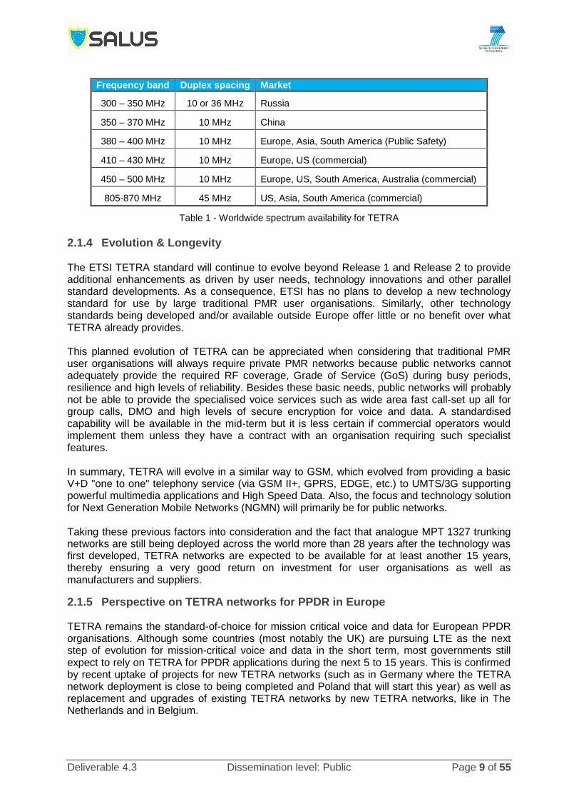
Recurring costs – the traffic profile from PPDR users might be different from regular
users and might incur high recurring costs especially if the traffic to be conveyed is high
(for instance a camera transmitting at 2 Mbps 4 hours a day would consume 110 GB per
month) and if the number of subscriptions is high. This recurring cost may represent few
m€ to 100 m€ per year and cumulated over a period of 10 years must 10s to 100s of m€
(Figure 7).
Deliverable 4.3 Dissemination level: Public Page 24 of 55
Figure 7 - Example of recurring cost for one year (Y=1) and cumulated over 10 years (Y = 1 to 10) as a
function of the PPDR subscribers [assumptions, unlimited data plan at 20€ / month subscription fee with
5% yearly discount]
3.1.1.2 PPDR MVNO – light Another MNO access based model to have access to broadband services is to set up a light mobile virtual network operator (MVNO). This model is called the light PPDR MVNO model in the document. In this model, three business models are possible:
Every single PPDR organisation establishes its owns light PPDR MVNO solution (called
light MVNO PPDR A),
One leading PPDR organisation establishes a unified light PPDR MVNO solution for all
PPDR organisations (called light MVNO PPDR B),
A trusted entity establishes a light PPDR MVNO and provides broadband services to all
in country PPDR organisations (light MVNO PPDR C).
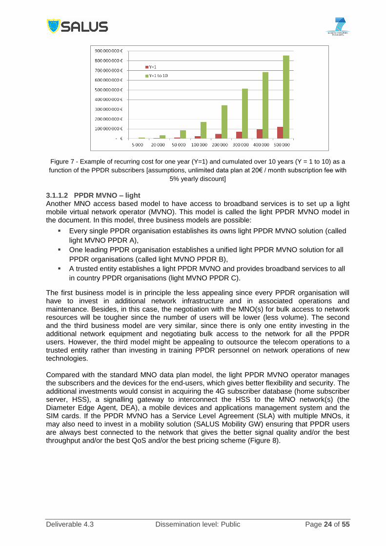
The first business model is in principle the less appealing since every PPDR organisation will have to invest in additional network infrastructure and in associated operations and maintenance. Besides, in this case, the negotiation with the MNO(s) for bulk access to network resources will be tougher since the number of users will be lower (less volume). The second and the third business model are very similar, since there is only one entity investing in the additional network equipment and negotiating bulk access to the network for all the PPDR users. However, the third model might be appealing to outsource the telecom operations to a trusted entity rather than investing in training PPDR personnel on network operations of new technologies. Compared with the standard MNO data plan model, the light PPDR MVNO operator manages the subscribers and the devices for the end-users, which gives better flexibility and security. The additional investments would consist in acquiring the 4G subscriber database (home subscriber server, HSS), a signalling gateway to interconnect the HSS to the MNO network(s) (the Diameter Edge Agent, DEA), a mobile devices and applications management system and the SIM cards. If the PPDR MVNO has a Service Level Agreement (SLA) with multiple MNOs, it may also need to invest in a mobility solution (SALUS Mobility GW) ensuring that PPDR users are always best connected to the network that gives the better signal quality and/or the best throughput and/or the best QoS and/or the best pricing scheme (Figure 8).
Deliverable 4.3 Dissemination level: Public Page 25 of 55
Figure 8 - High level simplified architecture for light PPDR MVNO
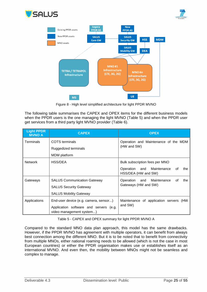
The following table summarises the CAPEX and OPEX items for the different business models when the PPDR users is the one managing the light MVNO (Table 5) and when the PPDR user get services from a third party light MVNO provider (Table 6).
Light PPDR MVNO A
CAPEX OPEX
Terminals COTS terminals
Ruggedized terminals
MDM platform
Operation and Maintenance of the MDM
(HW and SW)
Network HSS/DEA Bulk subscription fees per MNO
Operation and Maintenance of the
HSS/DEA (HW and SW)
Gateways SALUS Communication Gateway
SALUS Security Gateway
SALUS Mobility Gateway
Operation and Maintenance of the
Gateways (HW and SW)
Applications End-user device (e.g. camera, sensor...)
Application software and servers (e.g.
video management system...)
Maintenance of application servers (HW
and SW)
Table 5 - CAPEX and OPEX summary for light PPDR MVNO A
Compared to the standard MNO data plan approach, this model has the same drawbacks. However, if the PPDR MVNO has agreement with multiple operators, it can benefit from always best connection among the different MNO. But it is to be noted that to benefit from connectivity from multiple MNOs, either national roaming needs to be allowed (which is not the case in most European countries) or either the PPDR organisation makes use or establishes itself as an international MVNO. And even then, the mobility between MNOs might not be seamless and complex to manage.

Deliverable 4.3 Dissemination level: Public Page 26 of 55
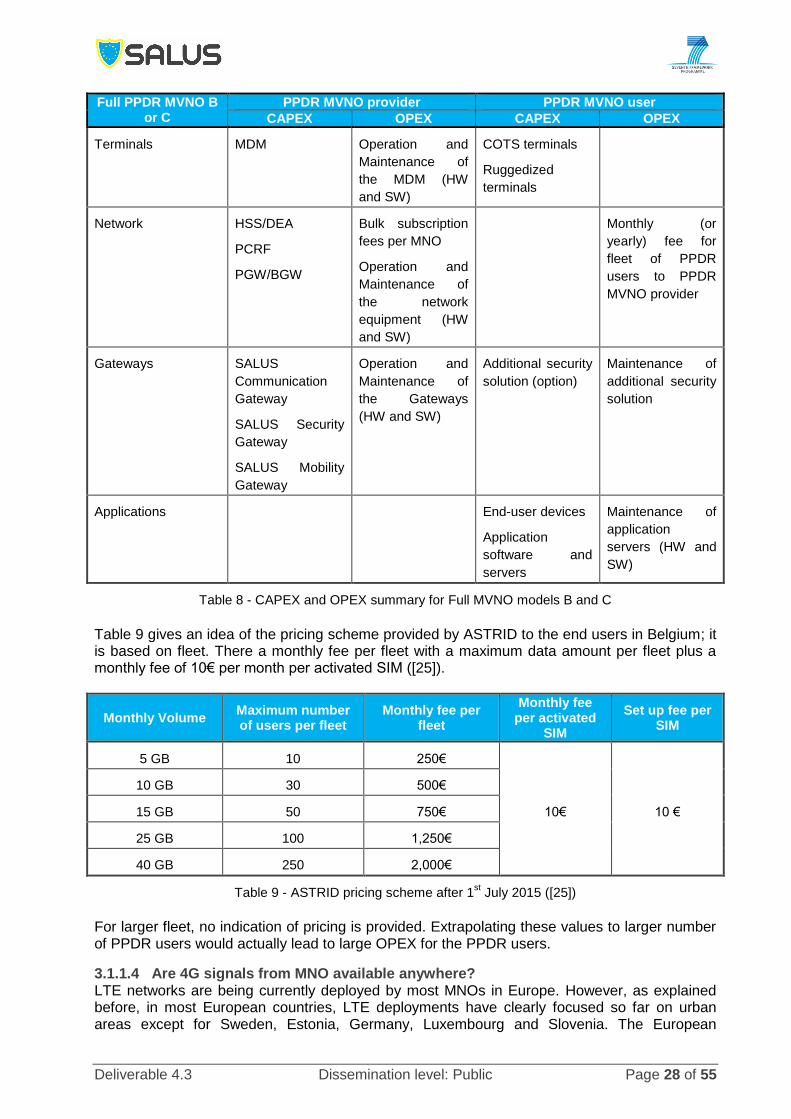
Light PPDR MVNO B or C
PPDR MVNO provider PPDR MVNO user
CAPEX OPEX CAPEX OPEX
Terminals MDM Operation and
Maintenance of
the MDM (HW
and SW)
COTS terminals
Ruggedized
terminals
Network HSS/DEA
Bulk subscription
fees per MNO
Operation and
Maintenance of
the HSS/DEA
(HW and SW)
Monthly (or
yearly) fee for
fleet of PPDR
users to PPDR
MVNO provider
Gateways SALUS
Communication
Gateway
SALUS Security
Gateway
SALUS Mobility
Gateway
Operation and
Maintenance of
the Gateways
(HW and SW)
Additional security
solution (option)
Maintenance of
additional security
solution
Applications End-user devices
Application
software and
servers
Maintenance of
application
servers (HW +
SW)
Table 6 - CAPEX and OPEX summary for light MVNO models B and C
3.1.1.3 PPDR MVNO - Full
Figure 9 - Simplified High Level Full PPDR MVNO architecture
The Full PPDR MVNO model is an extension of the light PPDR MVNO model. In that case, the PPDR MVNO provider also invests in additional LTE core network equipment (PGW and PCRF)

Deliverable 4.3 Dissemination level: Public Page 27 of 55
and a Border Gateway (BGW) connecting to the IP exchange (IPX) network interconnecting LTE mobile networks. Compared with the light PPDR MVNO model, this gives additional control on services and on end-to-end QoS over the LTE access network. Indeed, the PCRF deployed in the full PPDR MVNO will enforce the E2E QoS from the PGW that is connected to the MNO access network (Figure 9). The business models are basically the same as for the light PPDR MVNO (in the following, the identification of the model names will follow the same logic as in §3.1.1.2 replacing “light” by “full”); however, the PPDR MVNO provider may also get the infrastructure services from a mobile virtual network enabler (MVNE). This latter model is the model used in Belgium by ASTRID, the government entity operating the professional services for PMR users in Belgium (PPDR, Transport, Utilities...) [24]. The following tables summarise the CAPEX and OPEX items for the different business models when the PPDR users is the one managing the Full PPDR MVNO (Table 7) and when the PPDR user get services from a third party Full PPDR MVNO provider (Table 8).
Full PPDR MVNO A
CAPEX OPEX
Terminals COTS terminals
Ruggedized terminals
MDM platform
Operation and Maintenance of the MDM
(HW and SW)
Network HSS/DEA
PCRF
PGW/BGW
Bulk subscription fees per MNO
Operation and Maintenance of the network
equipment (HW and SW)
Gateways SALUS Communication Gateway
SALUS Security Gateway
SALUS Mobility Gateway
Operation and Maintenance of the
Gateways (HW and SW)
Applications End-user device (e.g. camera, sensor...)
Application software and servers (e.g.
video management system...)
Maintenance of application servers (HW
and SW)
Table 7 - CAPEX and OPEX summary for Full PPDR MVNO A
Compared to the light PPDR MVNO model, the Full PPDR MVNO model provides more control on E2E QoS for the PPDR applications in the coverage area of the MNOs. However, it still suffers from the other drawbacks. Another interesting point of this model is that it can also be seen as a relevant first step towards dedicated broadband PPDR. Indeed, all the LTE core components that would be deployed by the Full PPDR MVNO provider can also be used in a later step to be used as LTE core network components for a dedicated PPDR LTE access network. As already mentioned, ASTRID is following this approach to provide “non mission critical data” services to its subscribers. They rely on a MVNE that ensures the connectivity to the different Belgian mobile operator and also roaming to neighbouring countries. Another example of this model is the Emergency Services Mobile Communications Program (ESMCP) by the UK Home Office. The objective in that case is quite ambitious; completely replacing the TETRA network managed by Airwave by an LTE only network relying on a MNO network and an Emergency Services provider (i.e. a Full PPDR MVNO provider). This program is in tender stage at the time of writing this report.
Deliverable 4.3 Dissemination level: Public Page 28 of 55
Full PPDR MVNO B or C
PPDR MVNO provider PPDR MVNO user
CAPEX OPEX CAPEX OPEX
Terminals MDM Operation and
Maintenance of
the MDM (HW
and SW)
COTS terminals
Ruggedized
terminals
Network HSS/DEA
PCRF
PGW/BGW
Bulk subscription
fees per MNO
Operation and
Maintenance of
the network
equipment (HW
and SW)
Monthly (or
yearly) fee for
fleet of PPDR
users to PPDR
MVNO provider
Gateways SALUS
Communication
Gateway
SALUS Security
Gateway
SALUS Mobility
Gateway
Operation and
Maintenance of
the Gateways
(HW and SW)
Additional security
solution (option)
Maintenance of
additional security
solution
Applications End-user devices
Application
software and
servers
Maintenance of
application
servers (HW and
SW)
Table 8 - CAPEX and OPEX summary for Full MVNO models B and C
Table 9 gives an idea of the pricing scheme provided by ASTRID to the end users in Belgium; it is based on fleet. There a monthly fee per fleet with a maximum data amount per fleet plus a monthly fee of 10€ per month per activated SIM ([25]).
Monthly Volume Maximum number of users per fleet
Monthly fee per fleet
Monthly fee per activated
SIM
Set up fee per SIM
5 GB 10 250€
10€ 10 €
10 GB 30 500€
15 GB 50 750€
25 GB 100 1,250€
40 GB 250 2,000€
Table 9 - ASTRID pricing scheme after 1st July 2015 ([25])
For larger fleet, no indication of pricing is provided. Extrapolating these values to larger number of PPDR users would actually lead to large OPEX for the PPDR users.
3.1.1.4 Are 4G signals from MNO available anywhere? LTE networks are being currently deployed by most MNOs in Europe. However, as explained before, in most European countries, LTE deployments have clearly focused so far on urban areas except for Sweden, Estonia, Germany, Luxembourg and Slovenia. The European

Deliverable 4.3 Dissemination level: Public Page 29 of 55
Commission maintains a scoreboard for broadband market that gives 4G penetration (% of population) in the different member states including penetration in rural area. It definitely shows, as of today, LTE coverage is not widely available (Figure 10).
Figure 10 - 4G penetration in the member states in 2013 ([26])
The picture looks even worse when looking at the statistics of geographical coverage vs. population coverage. Below are a few examples of some member states 4G deployment coverage statistics that illustrate that. In France, according to a report from the French regulator (ARCEP), although some operators provide 4G services to 70% of the population, this actually represents only 22% of the geographical coverage. In comparison, 3G covers nearly 99% of the population and covers almost 90% of the country [27]. It is to be noted that based on regulatory objectives, French commercial operators have a target to cover 75% of the French metropolitan territory by October 2023, 98% of the territory by January 2024 and 99.8% of the territory by January 2027.
Figure 11 - 4G coverage in France, July 2014 ([27])
In UK, Ofcom has recently published statistics on 4G coverage. It shows that although 72% of the premises are covered by at least 1 operator, there is 77% of the territory where there is no 4G signal available. It also shows that 25% of the motorways and 63% of roads are not covered by 4G (Figure 12). It is to be noted that current spectrum award for LTE include coverage obligations based on population (e.g. 98% of UK population and 95% of each England, Scotland, Wales, and Ireland by end 2017) and not landmass.

Deliverable 4.3 Dissemination level: Public Page 30 of 55
Figure 12 - UK 4G mobile network coverage, June 2014 ([28])
In the final version of the report, additional statistics (percentage of population and land covered and regulatory objectives and timing) from multiple member states will be provided.
3.1.1.5 The role of Wi-Fi in getting services from MNO Wi-Fi services via MNO networks can enhance the MNO business model. The expansion of Wi-Fi networks via LTE infrastructure can enhance mobility and interoperability as well as broadband services especially in areas where wired infrastructure may suffer and thus provide generic connectivity. In cases where there is need for access in remote, out band elements [29], MNO infrastructure can provide connectivity and thus provide the platform for Wi-Fi services and thus enhance its business model. Moreover, as part of the extension of broadband connectivity in rural areas the so-called “white areas” [30], where dated wired infrastructure and irregular terrain conditions do not allow for fibre optics and/or broadband cabling, MNO deployment can also provide Wi-Fi accessibility and thus significantly enriching the business model in both terms of user growth, market penetration in terms of geography, demographics, and traffic load, and also in potential pricing of services [31]. Wi-Fi can play a key role in the MNO business model in terms of capacity improvement and coverage extension. Wi-Fi Offload can assist MNO where needed, as complementary solution in outdoor scenarios or as an extension in indoor environments [51], [52]. An example of such model is the “Carrier Hampton” Business Plan is a Local-Loop Whole Sale Provider deployed in the suburbs of Peterborough, UK [53] and can also provide solution for PPDR services, albeit stationary. In this deployment there are two types of customers:
Direct Customers - Private customers, who use the Wi-Fi Internet Broadband connection
with their Laptop, their smart phone, a Wi-Fi-USB Stick or a Wi-Fi card for their PC or a
special Wi-Fi router for dedicated or very remote lines. The Police (surveillance
cameras) and schools and universities or other large organizations can also become
direct customers with a dedicated line.
Indirect Customers - Internet Service Provider (ISP), Mobile Service Providers, which
either have to use the „Local Loop“ of British Telecom or have to rely on radio network
with a low data bandwidth capacity, can use the offered local loop with their customers.
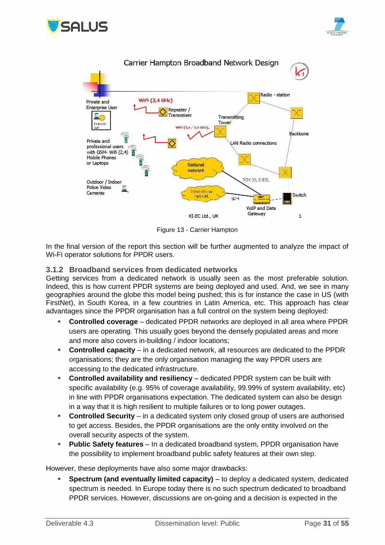
Deliverable 4.3 Dissemination level: Public Page 31 of 55
Figure 13 - Carrier Hampton
In the final version of the report this section will be further augmented to analyze the impact of Wi-Fi operator solutions for PPDR users.
3.1.2 Broadband services from dedicated networks Getting services from a dedicated network is usually seen as the most preferable solution. Indeed, this is how current PPDR systems are being deployed and used. And, we see in many geographies around the globe this model being pushed; this is for instance the case in US (with FirstNet), in South Korea, in a few countries in Latin America, etc. This approach has clear advantages since the PPDR organisation has a full control on the system being deployed:
Controlled coverage – dedicated PPDR networks are deployed in all area where PPDR
users are operating. This usually goes beyond the densely populated areas and more
and more also covers in-building / indoor locations;
Controlled capacity – in a dedicated network, all resources are dedicated to the PPDR
organisations; they are the only organisation managing the way PPDR users are
accessing to the dedicated infrastructure.
Controlled availability and resiliency – dedicated PPDR system can be built with
specific availability (e.g. 95% of coverage availability, 99.99% of system availability, etc)
in line with PPDR organisations expectation. The dedicated system can also be design
in a way that it is high resilient to multiple failures or to long power outages.
Controlled Security – in a dedicated system only closed group of users are authorised
to get access. Besides, the PPDR organisations are the only entity involved on the
overall security aspects of the system.
Public Safety features – In a dedicated broadband system, PPDR organisation have
the possibility to implement broadband public safety features at their own step.
However, these deployments have also some major drawbacks:
Spectrum (and eventually limited capacity) – to deploy a dedicated system, dedicated
spectrum is needed. In Europe today there is no such spectrum dedicated to broadband
PPDR services. However, discussions are on-going and a decision is expected in the

Deliverable 4.3 Dissemination level: Public Page 32 of 55
next WRC by November 2015. Besides, unlike narrow-band systems where eventually
each organisation could have access to a few resources, the future broadband PPDR
spectrum will have to be shared between all PPDR organisations (and may be with other
critical infrastructure operators). Moreover, since this potential spectrum is in competition
with spectrum for commercial operator, there is a risk that the resulting spectrum might
be less than what is requested (2x10 MHz are requested by the PPDR community for
data services only). In that case, the resulting capacity on a dedicated network can be
limited.
Cost of deployment – deploying a new network on a large geographical scale will incur
significant investments that need to be planned in advance. Depending on the frequency
band that will be allocated for broadband PPDR services and on the output power of the
LTE terminals, the required number of sites may be significantly higher than the actual
number of sites currently deployed for TETRA or TETRAPOL to cover a similar
geography.
Skills – PPDR organisations may have today network operation teams managing the
existing narrow-band circuit-switched based network. With next generation PPDR
system based on LTE and IP, a new and different set of skills will be required.
Time to service – Deployment of a PPDR network usually takes time (the deployment
of TETRA / TETRAPOL network took several years). Indeed, to have a successful
deployment happening, there is a need to have a budget matching the requirement, to
have the radio sites (prepared) for deploying the new system, to have the right skills and
to train the PPDR officers to use the new technology.
A successful deployment of a dedicated broadband PPDR system will need to address the previous points. Multiple business models may exist to deploy and operate this dedicated system but in any case, the owner of the system will have to invest in a complete new infrastructure. To limit the upfront investment, the PPDR organisation may deploy the broadband system in a limited geography. For instance the deployment may start with a few key areas where the need for broadband would be the higher (main cities, main roads...). Whatever the business model to be used, deploying a dedicated network will consist of deploying a complete LTE network consisting of (see Figure 14):
Figure 14 - Dedicated LTE network (simplified)

Deliverable 4.3 Dissemination level: Public Page 33 of 55
LTE Terminals and associated device management platform and applications,
LTE Radio access network (the eNodeBs).
LTE core network (unicast and broadcast mode).
Besides, in addition to the above mentioned components, the PPDR organisation might also have to invest in renovating the backhaul network to align it to the requirements of an LTE network (bandwidth, protocols, interfaces, security, synchronisation...).
3.1.2.1 Different business models for getting dedicated broadband services Build, own and operate – in this model, the PPDR organisation finances, procures, build and manages its own network. It takes full responsibility for all network elements and software, and employs in-house personnel to build, manage, operate and maintain the network. It is to be noted that due to spectrum constraint, only one radio access network will be built and shared by all PPDR organisations. A leading PPDR organisation (or a government body) will then take care of the deploying, maintaining and operating the radio access network. Besides, it is recommended to also have a single core network for all the agencies and to have the same leading entity managing it. With the advance of technology to Network Function Virtualisation (NFV) it will be possible, if desired, to create multi-tenant virtual EPC. Table 10 gives the CAPEX and OPEX items for the PPDR organisation building, owning and maintaining the broadband PPDR network.
Build Own and Operate
CAPEX OPEX
Terminals COTS terminals.
Ruggedized terminals
MDM platform
Operation and Maintenance of the MDM
(HW and SW) with in-house personnel
Network eNodeB
EPC (S-GW, P-GW, PCRF, MME, HSS,
BM-SC, MBMS GW)
Packet based Backhaul (if owned)
Operation and Maintenance of the network
equipment (HW and SW) with in-house
personnel
Leased lines for backhaul (if leased)
Gateways SALUS Communication Gateway
SALUS Security Gateway
SALUS Mobility Gateway
Operation and Maintenance of the
Gateways (HW and SW) with in-house
personnel
Applications End-user device (e.g. camera, sensor...)
Application software and servers (e.g.
video management system...)
Maintenance of application servers (HW
and SW) with in-house personnel
Table 10 - CAPEX and OPEX summary for Build, Own and Operate
Own and outsource operations – This model is very similar to the previous one but instead of having in-house personnel managing the network, the network operations are outsource to a specialised company. The service paid to the specialised company may also include upgrades of the system Public Private Partnership - the LTE network is deployed, operated and maintained by an independent operator. This type of network is typically owned by a commercial MNO, which provides the service to the PPDR organisations while usually assuming the financial, technical and operational risk of the service offer. The MNO may use part of its existing infrastructure to optimise the total cost of ownership of the network (e.g. sharing of radio sites, sharing of

Deliverable 4.3 Dissemination level: Public Page 34 of 55
backhaul, etc). It is to be noted that in this model, (and if regulation and legislation allow this mode of operation), it might be possible to “monetize” part of the dedicated PPDR spectrum and open its use to commercial users during off-peak period of the broadband PPDR network. From a technical point of view that would be possible using LTE RAN sharing option. Table 11 gives the CAPEX and OPEX items for the PPDR organisation and the company providing the PPDR services. It is to be noted that this table indicates the “electronics” part. A global CAPEX and OPEX list should also consider real estate, civil engineering (if needed), power supply, air-conditioning, physical perimeter security, etc which are usually quite high.
Public Private Partnership
PPDR Service provider PPDR user
CAPEX OPEX CAPEX OPEX
Terminals MDM Operation and
Maintenance of
the MDM (HW
and SW)
COTS terminals
Ruggedized
terminals
Network LTE eNode B
LTE EPC
(packet based
backhaul)
Operation and
Maintenance of
the network
equipment (HW
and SW)
Annual/monthly
fees for managed
services of
network
components
Gateways SALUS
Communication
Gateway
SALUS Security
Gateway
SALUS Mobility
Gateway
Operation and
Maintenance of
the Gateways
(HW and SW)
Additional security
solution (option)
Maintenance of
additional security
solution
Annual/Monthly
fees for managed
services of
network
components
Applications End-user devices
Application
software and
servers
Maintenance of
application
servers (HW +
SW)
Table 11 - CAPEX and OPEX summary for the Public Private Partnership model
3.1.2.2 Role of Wi-Fi complementing dedicated PPDR LTE networks For European scenarios we need to focus on the availability and reliability of dedicated Wi-Fi networks for PPDR services. The main disadvantage of 802.11b/g/n networks [32]-[37] is the lack of a centrally-planned infrastructure that can provide robust coverage of an urban area, considering that metropolitan area networks at the 2.4 GHz are in many cases the product of “bottom-up” networking by communities of users. So coverage may or may not be present at a given location. Co-channel interference can provide another disadvantage for Wi-Fi access for PPDR services, as Wi-Fi hotspots are deployed without central planning and can co-exist in a way that each hotspot becomes hostile to the others in terms of electro-magnetic radiation. On the other hand, Wi-Fi access can provide a more reliable solution, either in obstacle-dense micro cells where a base station may not be able to service a mobile user in the presence of shadowing due to physical obstacles or in an indoor environment where outdoor-to-indoor penetration of 3G/4G access might be weaker. Moreover, in macro-BS deployment, the user

Deliverable 4.3 Dissemination level: Public Page 35 of 55
moving at cell boundary may suffer from deep fades and marginal signal reception whereas an approximate Wi-Fi hotspot, albeit randomly deployed (either in residential or enterprise topology) can provide a reliable access solution for PPDR services. Respective business models for Wi-Fi networks and especially Public WLANs (PWLAN) that can assist in PPDR services provided by dedicated LTE networks have been evaluated according to the IDEA (Identify, Design, Evaluate, Aggregate) framework, as shown in Figure 15 [41]-[42].
Figure 15 -IDEA framework
The task of “Module I” is to Identify the need for business innovation, when the assumed considerations have changed. These considerations refer to the technological capacities and their presumed impact on business reshaping. The next step is to identify the new possibilities of the redesigning of the business models – what is called the new design possibilities. The result of “Module D” is to Design a set of new business models using the new design possibilities identified in “Module I”. In “Module E”, the potential business models, which were identified in the “Module D”, are Evaluated, with the criterion of market success. All business models that are considered for evaluation are ranked according to their performance in assumed market scenarios. In “Module A”, the business models are Aggregated in a value chain. All identified business models are placed in the value chain with regard to the value – adding activities they deliver in this industry. Afterwards, the interactions between the business models are analyzed. There are three kinds of interaction: (1) Service Relationship, (2) Competition, (3) Alliances / Coalitions [43]. Figure 16 demonstrates all possible identified and sustainable business models for the Public WLAN market, after excluding irrational combinations of possible scenarios.

Deliverable 4.3 Dissemination level: Public Page 36 of 55
Figure 16 - Identified and Sustainable Public WLAN Business Models
These business models as well as alliances in the global PWLAN market reflect not only the actual traffic of PWLAN providers and users, but also the challenges in the technological issues still open for wireless networks and services, including PPDR Services for both stationary and (low-speed) vehicular scenarios [44]- [49]. In the final version of the deliverable this analysis will be extended to PPDR case.
3.1.3 Systems on wheels Mobility of PPDR users in many cases is “vehicle powered” mobility. In many scenarios, the PPDR user is inside a vehicle or in the vicinity of his vehicle when executing his duties. The PPDR vehicles might then be the physical backbone of the PPDR operations. As a result, considering the use of PPDR vehicles as a natural bearer of PPDR (communications) equipment is very logical. Vehicles can actually carry communications equipment for a number of purposes. First there is PPDR related information and control tightly connected to the vehicle as such. This interaction is through vehicle mounted sensors and actuators. The most common used sensor is GPS for the vehicle position (usually called automatic vehicle location, AVL). But other sensors are also of interest. Some examples are:
Door opening / closing - when a door is opened while the vehicle is close to the location
of an incident, one may conclude that the vehicle is “on the scene”, triggering a status
notification to a dispatch room,
Sensors measuring supplies - e.g. communicating the measured water o supply can
trigger the organisation to arrange for refill
Video and sound sensors – vehicles are more and more equipped with video camera
that can record images and sound that can be used to transmit raw and/or processed
information to the command and control centres and to play-back records of interest.
The vehicle is also the typical place to have computer based access to databases or video applications. The vehicle is more than a “mobile office”. This application includes a vehicle mounted computer, with keyboard, display and maybe some other peripherals.
Deliverable 4.3 Dissemination level: Public Page 37 of 55
Both vehicle specific systems, as well as a vehicle mounted computer require an infrastructure link, which commonly is LTE-based in the SALUS context. The vehicle however is also the correct carrier for repeater-like systems. The vehicle may contain a “Mobile Node” (MN). Such MN is a router that extends the infrastructure towards mobile clients. This exploits the strength of the vehicle, which can be equipped with better antennas, and with more radios for various networks (to perform always best connection or to aggregate bandwidth from multiple networks). An even more extreme scenario is when the infrastructure completely lacks in a specific environment. One scenario is a typical disaster scenario where (significant parts of) the infrastructure is lacking at the operational scene (such as use case 3 – disaster recovery - as described in SALUS deliverable D2.3 [50]). The typical reasons would be calamities like power outage or physical damages to parts of the infrastructure due to landslides, hurricanes, intense cold or heat, etc. The other typical scenario is a remote location, outside of the coverage of the infrastructure, like in mountainous terrains. In such scenarios, the vehicle based system, or typically more a system on wheels is a stand-in infrastructure to temporally replace the infrastructure. The MN may maintain three different types of connections:
Client on an infrastructure,
Infrastructure for mobile clients,
Part of an ad-hoc network to create an ad-hoc backbone.
Each of these types of connections needs to be exploited to its maximum for high quality communications.
3.1.3.1 Client on an infrastructure A MN may be equipped with multiple radios for the infrastructure connection. When the multiple radios are all LTE-based, each radio may be linked to a different operator (this may include commercial and/or PPDR operator). By doing so, the MN can maximize the quality for its users by combining the quality of the individual networks. Combining this quality can have different shapes. Well known principles are load-balancing, QoS-aware routing and link aggregation. In case of load-balancing and QoS-aware routing the MN will decide per traffic stream which radio to use. The principle of load balancing aims for balancing the load over the available links, creating as much as possible a constant quality. The principle of QoS-aware routing considers the QoS requirements per traffic stream in its decision, which will lead to a more differentiated performance. In case of link aggregation, the available links are combined into a single “bit pipe”. This caters for a very high capacity link, but prevents the LTE system to be QoS-aware with respect to the individual traffic streams. Being vehicle mounted also caters for use of high gain antennas, and is placed at a higher location. A vehicle mounted omni-directional antenna may have a gain of 6-8 dBi, whereas a handheld device typically has close to 0 dBi antennas. The use of directional antenna on vehicles could be applicable in some scenarios, leading to antenna gains of 14-16 dBi in realistic use cases. That would enable larger reach and./or better data rates around the vehicle location compared to handled connection to the wide area network. Besides LTE, a MN may also connect to the infrastructure using a different technology. Satellite communication is a frequently used back-up (but with limited bandwidth and extra delays), whereas land-line (based on microwave links or wired connection) may be an option in semi-static cases as well.
3.1.3.2 Infrastructure for mobile clients A MN will be equipped with technology to provide access to mobile clients. The MN may cater this using a range of technologies. Within the scope of the SALUS architecture one may see at least the following options:
Deliverable 4.3 Dissemination level: Public Page 38 of 55
WLAN Access Point,
LTE – (small) cell,
Sensor network technology.
A WLAN AP can provide access to a large variety of end-user devices. All state-of-the-art smartphones have WLAN capabilities, so can access a network through the MN. Also other devices, like CCTV cameras, and much consumer grade equipment is WLAN capable. This makes that more or less any device can be linked to the system, being specially designed for PPDR use or not. Providing WLAN Access Point capabilities enables Bring Your Own Device (BYOD) strategies. It also enables easy adaption of business or consumer solutions in the PPDR scope, avoiding specific design effort that is not cost efficient for PPDR specific design only, while being efficient for the large public of consumers or business users. A second technology that may be integrated in the same MN is LTE. The MN can act as an LTE (small) cell. This could be defined as a cell of one of the existing LTE infrastructure, or could have a separate network code. Using the same network code leads to mobility control being handled by the infrastructure. Using a separate network code would better fit ad-hoc network aspect of the overall solution. The sensor network option is a third group of technologies. Wireless sensors are part of the upcoming so called IoT. Wireless sensors will enable detailed vision on the field of operation, so will feed the common operational picture. The technology for wireless sensors is not yet very standardized, containing a large group of alternative solutions. A common denominator is the term Low Power Wide Area (LPWA). A selection from these technologies needs to be made for a specific implementation.
3.1.3.3 Ad-hoc network as backbone When multiple vehicles are within one’s vicinity, the vehicles can create a local ad-hoc network. The main purpose of this ad-hoc network is to create a robust in-field backbone for communication. End-user devices are connected as described above, the ad-hoc network extends the infrastructure. The technology of the ad-hoc network can be chosen completely independent from the technologies discussed above, so the technologies for accessing the infrastructure and for creating access to end-user devices. The most logical technologies for access and possibly the ad-hoc backbone are WLAN and LTE. WLAN has the big advantage of being license exempt, implying that no licensing issues arise when deploying the system in ad-hoc situations. WLAN is a possible technology for this ad-hoc network. WLAN can run in ad-hoc mode, which implies that there is no coordination point within this ad-hoc network. Each MN is responsible for creating its own communication environment. This environment includes at least the physical, networking and security aspects. As the MNs need to be able to communicate also when communication to the infrastructure is impossible, such aspects need pre-configuration. The main merits of WLAN ad-hoc networking as backbone for on-scene communications are:
Pros:
o Additional robustness,
o No need for licensed spectrum,
o Very cheap, so easily deployed,
o Multiple hops possible.
Cons:
o Ad-hoc networks still require a backbone to connect to the main (strategic and/or
tactical level) command and control centre and local application in clients if there
is no connection to the main network/applications; it is not a solution in itself,
o Use of licence exempt spectrum may be impossible due to high load and/or high
interference in the area of deployment,

Deliverable 4.3 Dissemination level: Public Page 39 of 55
o Range of ad-hoc networks is usually limited due to power limitations in
unlicensed bands.
LTE is certainly the other available technology for ad-hoc deployment. In particular the ProSe extension (Proximity Services), which is currently under development, could be used. ProSe provides the option of direct Device to Device communication between LTE devices, but also the option of creating a local network, using only the local eNodeB. ProSe will support unicast, groupcast, broadcast and relying, creating a complete suite of functions to fulfilling any communications requirement. The merits of this approach are the following:
Pros:
o Same terminal technology as for day-to-day operation,
o High bandwidths possible at good ranges,
o No need for additional spectrum (to be confirmed depending on ProSe
implementation options –in band or out of band-),
Cons:
o Technology still under development,
o It remains to be a local network, with limited range,
o Needs coordination with network for spectrum sharing in case of in-band mode,
o One hop only for D2D or 2 hops maximum in case of Network to device relays.
3.1.3.4 System on wheels options Based on the above information, two generic MN can be defined: a MN for coverage and/or capacity extensions (MN – CCE) and a MN for disaster recovery (MN - DR). Also, although the previous sub-sections are dealing with broadband communications, the MN may include a narrowband component. Figure 17 depicts the simplified architecture of the MN - CCE. In this case, the MN consists of mobile gateways connecting to the wide area cellular network on one side and retransmitting the signals on the terminal side. All applications / SALUS gateways are in the back-office. Main CAPEX and OPEX items for this option are listed in Table 12.
Figure 17 - Simplified high level architecture of MN – CCE

Deliverable 4.3 Dissemination level: Public Page 40 of 55
MN-CCE CAPEX OPEX
Terminals COTS terminals.
Ruggedized terminals
MDM platform
Operation and Maintenance of the MDM
(HW and SW) with in-house personnel
Mobile Node Cellular GW (to connect to the cellular
backbone)
LTE Relay (ProSe UE or LTE –small- cell)
Wi-Fi AP
Operation and Maintenance of the network
equipment (HW and SW) with in-house
personnel
Cellular
Backbone
Dedicated LTE infrastructure (option) Cellular subscription
Gateways
(back-office)
SALUS Communication Gateway
SALUS Security Gateway
SALUS Mobility Gateway
Operation and Maintenance of the
Gateways (HW and SW) with in-house
personnel
Applications
(back-office)
End-user device (e.g. camera, sensor...)
Application software and servers (e.g.
video management system...)
Maintenance of application servers (HW
and SW) with in-house personnel
Table 12 - CAPEX and OPEX summary for MN - CCE
Figure 18 depicts the simplified architecture of the MN - DR. In this case, the MN consists of complete systems in a box (LTE; Wi-Fi, TETRA and/or TETRAPOL) and also implements all applications / SALUS gateways. Main CAPEX and OPEX items for this option are listed in Table 13.
Figure 18 - Simplified high level architecture of MN – DR

Deliverable 4.3 Dissemination level: Public Page 41 of 55
MN-DR CAPEX OPEX
Terminals COTS terminals.
Ruggedized terminals
MDM platform
Operation and Maintenance of the MDM
(HW and SW) with in-house personnel
(preparation phase) and by local personal
to the incident (response phase)
Mobile Node LTE in a box (RAN, EPC, NMS)
Wi-Fi AP
SALUS Communication Gateway
SALUS Security Gateway
SALUS Mobility Gateway
End-user device (e.g. camera, sensor...)
Application software and servers (e.g.
video management system...)
Operation and Maintenance of the network
equipment, Gateways and applications (HW
and SW) with in-house personnel
(preparation phase) and by local personal
to the incident (response phase)
Backbone Satellite modem
Wi-Fi Ad-hoc or other for
Satellite service subscription
Table 13 - CAPEX and OPEX summary for MN – DR
3.1.4 Hybrid models Previous sections have presented individual deployment models and have showed that there is not a single perfect model based on an individual approach. However, in next generation PPDR networks, since the access technologies that will be used are based on commercial standard (LTE, Wi-Fi), this opens also the possibility to combine the previous individual models to get the best of them. In a resulting hybrid model:
The dedicated wireless broadband system provides a high priority, guaranteed
bandwidth for the mission-critical applications always available for PPDR organisations
for emergency and disaster response.
The commercial MNO(s) broadband network can be used as network providing extra-
capacity and off-load capabilities for lower priority applications and traffic to further
improve the mission-critical aspect of the dedicated network.
The system on wheels can be used to provide extended coverage and/capacity (via
connections to the dedicated and commercial networks) or full autonomous systems in
case of major breakdown of the infrastructure.
3.2 Merits of the possible models
The following tables give an indicative and high-level view of the merits of the different models discussed in the previous sections. It utilises a five point rating scale with the following colour code:
Red: Poor
Orange: Fair
Yellow: Good
Light green: Very good
Green: Excellent
In the final version of the deliverable, the merits that are subjective in the following tables will be refined using objective values (especially for the CAPEX and OPEX part that will be derived for the SALUS techno-economical tool).

Deliverable 4.3 Dissemination level: Public Page 42 of 55
Model
CA
PE
X
(Netw
ork
)
OP
EX
(Netw
ork
CA
PE
X
(Term
inals
)
OP
EX
(Term
inals
)
Tim
e T
o
Serv
ice
Co
vera
ge
(Cit
y)
Cap
acit
y
Cit
y)
Co
vera
ge
(ru
ral)
Cap
acit
y
(ru
ral)
Hig
h
Avail
ab
ilit
y
Co
ntr
ol
Pu
blic
Safe
ty
featu
res
Secu
rity
Standard MNO
data plan
Light PPDR MVNO
Full PPDR MVNO
Full PPDR MVNO
with specific SLAs
Build Operate and
Maintain (city)
Build Operate and
Maintain (National)
Own and outsource
operations
Public Private
partnership
MN – CCE
MN - DR
Hybrid model (city)
Hybrid model
(National)
Table 14 - Merits of the different models (low number of PPDR users with broadband capabilities)

Deliverable 4.3 Dissemination level: Public Page 43 of 55
Model
CA
PE
X
(Netw
ork
)
OP
EX
(Netw
ork
CA
PE
X
(Term
inals
)
OP
EX
(Term
inals
)
Tim
e T
o
Serv
ice
Co
vera
ge
(Cit
y)
Cap
acit
y
Cit
y)
Co
vera
ge
(ru
ral)
Cap
acit
y
(ru
ral)
Hig
h
Avail
ab
ilit
y
Co
ntr
ol
Pu
blic
Safe
ty
featu
res
Secu
rity
Standard MNO
data plan
Light PPDR MVNO
Full PPDR MVNO
Full PPDR MVNO
with specific SLA
Build Operate and
Maintain (city)
Build Operate and
Maintain (National)
Own and outsource
operations
Public Private
partnership
MN – CCE
MN - DR
Hybrid model (city)
Hybrid model
(National)
Table 15 - Merits of the different models (high number of PPDR users with broadband capabilities)

Deliverable 4.3 Dissemination level: Public Page 44 of 55
4 POSSIBLE MIGRATION SCENARIOS AND ROADMAP
4.1 Roadmap for “early” adopters
Early adopters are considering LTE as a disruptive technology that can replace TETRA and TETRAPOL in the short term (e.g. within the next 2 to 4 years). As with many other disruptive technologies, the potential indeed exists, but due to the current limitations explained in §2.3.2 LTE is not ready yet for mission critical communications, even when using private LTE networks. Current limitations of deploying standards-based LTE solutions for PPDR include:
Scalability - group oriented voice, data and video communication are poorly supported in
the current 3GPP standards for LTE, resulting in the need to use IP unicast instead of IP
broadcast to address multiple LTE terminals in one cell;
Security - the 3GPP standards-based authentication and encryption algorithms are not
public safety grade. This topic is indeed a key topic handled by SALUS project;
Robustness - the current LTE solutions are developed for operator networks, and do not
include extreme resilience features that are required for high availability as required for
PPDR networks;
Spectrum - no (harmonised) spectrum is available for deploying nationwide broadband
PPDR networks.
To overcome these limitations there are basically four strategies available as a first step to migrate from TETRA and TETRAPOL to LTE based critical communication in the short-term:
Use a proprietary LTE solution that addresses the current and temporary lack of
standard-based LTE solutions;
Use current standards-based LTE as an overlay network to existing TETRA and
TETRAPOL networks to deliver non-critical (broadband) data and video
communications;
Use current standards-based LTE as an overlay network to deliver non-critical voice
using proprietary Over-The-Top (OTT) services, data and video communications;
Use current standards-based LTE as an overlay network to deliver non-critical voice,
data and video communications using an open ecosystem for delivering Over-The-Top
(OTT) services.
The second step is the deployment of 3GPP Release 13 standards-based LTE with Group Communication, Proximity Services and eventually IOPS. Ideally, the first step should be aligned with the second step to deliver a smooth migration scenario, whereby no investments are wasted and no big-bang migration scenario applies. Another important consideration is the limited availability of spectrum and limited budgets for deploying private LTE networks for PPDR. Because no harmonised spectrum is available now for broadband PPDR communication below 1 GHz, both private and fast deployable LTE networks may need to temporarily operate on higher frequencies, like the licensed TDD LTE bands around 2.6 and 3.5 GHz (that usually have not been allocated to MNO in most European countries). This means that the coverage is severely limited and cost is prohibitive for building a nationwide private LTE network; as an indication nationwide coverage of The Netherlands using a 2.6 GHz LTE network would require approximately 4,000 base stations instead of just 600 using 400 MHz TETRA. However, and depending on the upcoming decision at WRC-15, it may be possible for few member states to deploy LTE on dedicated network at 700 MHz and/or 400 MHz in the short-term.

Deliverable 4.3 Dissemination level: Public Page 45 of 55
The SALUS consortium supports the development of standards-based critical communications by active participation of its members within 3GPP and ETSI technical working groups. In addition, pragmatic solutions are developed as a first step to integrate and later migrate from TETRA and TETRAPOL to LTE according the fourth strategy. The benefits and limitations of each of the migration strategies are listed in Table 16.
Aspect Proprietary LTE
Standard LTE Data & video
Standard LTE Prop. OTT
Standard LTE SALUS OTT
Solution for public LTE networks – – ++ + ++
Solution for private LTE networks + ++ ++ ++
Solution for fast deployable LTE + ++ ++ ++
Roaming public / private LTE – – + 0 / + ++
Feature set – – 0 / + ++
Integration with legacy PMR – n/a unknown ++
Scalability for group calls + n/a unknown –
Support of security services 0 / + – / 0 unknown +
Robustness 0 / + 0 0 0
Architecture prepared for Rel. 12 – – n/a unknown +
Vendor lock-in – – + + – +
Table 16 - Benefits and limitations of LTE migration strategies
Examples of applicable solutions include the following:
Proprietary LTE: Huawei eLTE or ZTE 4G-GoTa. It is to be noted that this approach is
not compatible with the use of commercial networks;
Standard LTE with support of data and video: standard web browser access as well as
generic and custom-specific applications running on LTE-connected notebooks,
smartphones and tablets;
Standard LTE with proprietary OTT apps: Motorola/TwistedPair, Kodiak InstaPoC (non
PoC version).
It is obvious that the first "proprietary LTE" strategy is not of interest for PPDR organisations, in particular because of vendor lock-in, no support of roaming to public LTE networks, and the limited feature set. Standard LTE based data and video applications are already wide deployed within PPDR organisations for non-critical applications, but these are limited to a few use cases only. Proprietary OTT solutions are definitely a choice as a first step for migration to LTE, especially to offload regular traffic from the TETRA and TETRAPOL networks, but are severely limited in terms of feature set and support of security services (note: will be analysed further in D6.5). The SALUS OTT solution overcomes this limitation by providing an extensive TETRA inspired feature set that is compatible with existing TETRA networks, also in terms of security services, and an ecosystem that is open for other partners as well. The roadmap for an early adopter could be the following. For member states getting dedicated spectrum for broadband PPDR below 1 GHz an example of roadmap is found in Figure 19. LTE deployment could start in main cities or main focus area. As soon as SALUS GWs are available, the PPDR organisation can integrate PTT application

Deliverable 4.3 Dissemination level: Public Page 46 of 55
and other applications such as location or body area sensors between broadband and narrowband systems. Then, as soon as mission critical features are available (usually 18 to 24 months after the standard), the PPDR organisation may upgrade the infrastructure software and refresh the broadband LTE terminals to benefit from latest ProSe enhancements. At this stage the PPDR organisation will have mission critical (MC) services on both the narrowband and dedicated broadband network. During all these steps, the PPDR organisation may also use one or several MNO to off-load non-mission critical traffic. Finally when the dedicated network coverage is as good as the TETRA or TETRAPOL network, the narrowband network can be decommissioned.
Figure 19 - Example of roadmap for early adopter and dedicated frequency below 1 GHz
An example of roadmap for early adopters with frequency band above 1 GHz is described in Figure 20. In this case, since the dedicated frequency band might be at a rather high frequency, it will not be possible to deploy a dedicated nationwide broadband PPDR network. However, with the dedicated frequency, PPDR organisation can use as a first step system on wheels to cover main events and invest in deploying a dedicated infrastructure in main cities and/or main focus areas. The consequence is that to benefit from broadband services nationwide, the PPDR organisation will have to establish a full MVNO using one (or more) MNO access networks and establish strict Service Level Agreement (SLA) with them so that they provide 1) Public Safety features on the MNO network, 2) ubiquitous nationwide coverage, 3) highly resilient network and 4) planned (and agreed) maintenance period to avoid outages in major planned event and control outages for all other cases. An example of roadmap for early adopters with high frequency band is described in Figure 21. In that case, the broadband service is only provided by the access network of an MNO over which the PPDR organisation can deploy MVNO services. Strict SLA with the MNO will ensure that the MNO upgrade and maintain its network so that it can provide the required services, features, resiliency and availability as described in the previous case.
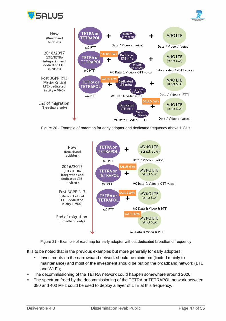
Deliverable 4.3 Dissemination level: Public Page 47 of 55
Figure 20 - Example of roadmap for early adopter and dedicated frequency above 1 GHz
Figure 21 - Example of roadmap for early adopter without dedicated broadband frequency
It is to be noted that in the previous examples but more generally for early adopters:
Investments on the narrowband network should be minimum (limited mainly to
maintenance) and most of the investment should be put on the broadband network (LTE
and Wi-Fi);
The decommissioning of the TETRA network could happen somewhere around 2020;
The spectrum freed by the decommissioning of the TETRA or TETRAPOL network between
380 and 400 MHz could be used to deploy a layer of LTE at this frequency.

Deliverable 4.3 Dissemination level: Public Page 48 of 55
4.2 Roadmap for “late” adopters
Late adopters are considering that LTE cannot replace TETRA and TETRAPOL in the short to mid-term (e.g. within the next 5 to 10 years). However, PPDR users of late adopters would also require broadband services in the short term. In that case, the PPDR organisations will probably favour an approach with:
Minimum investment on the broadband services; they would get ‘standard’ services from
a MNO (through e.g. a MVNO approach) and would only equip a limited number of
PPDR vehicles and officers with broadband services;
Continued investment on the existing TETRA and TETRAPOL systems with eventually a
mid-life refresh of this network giving an extra 10 to 15 years of services.
Figure 22 and Figure 23 give example of roadmap for late adopters. The steps are somehow similar to the ones described in the previous section but the intensity of deployment of the broadband services is low at the beginning and the overall timing spans 10 to 20 years instead of 5 years. Consequently, when the late adopters will start deploying broadband services, LTE systems will have all mission critical features available. Also, as for early adopters, when the TETRA or TETRAPOL network will be decommissioned, it may be possible to benefit from the freed spectrum to deploy a dedicated broadband network layer in this band.
Figure 22 - Example of roadmap for late adopter and dedicated frequency below 1 GHz

Deliverable 4.3 Dissemination level: Public Page 49 of 55
Figure 23 - Example of roadmap for late adopter without dedicated broadband frequency

Deliverable 4.3 Dissemination level: Public Page 50 of 55
5 CONCLUSIONS
This deliverable is the intermediate version of the SALUS business analysis and covers multiple aspects such as technology, business models and roadmap. It first gives an overview of the existing and emerging technologies that will be available for building future PPDR systems. That overview highlights that from a technology point of view, LTE will be ready for supporting mission-critical services starting from 2018+ (e.g. around 2 years after the completion of the 3GPP Release 13 standards). However, deploying a dedicated broadband network requires dedicated spectrum. At the time of writing this report, the decision of allocated dedicated (harmonized) spectrum across Europe has not been taken. Options are being discussed in 400 MHz band and/or in 700 MHz. More information will be available after WRC-15 (November 2015). In the final version of the business analysis deliverable, the technology section will be augmented with:
Advances in 3GPP standards regarding Public Safety features but also other features
that could be of interest for PDDR such as MTC, LTE-U (e.g. LTE in unlicensed bands)
or 5G;
Advances in decisions on dedicated broadband for PPDR.
The second main section describes the different possible business models to deploy a broadband PPDR system. This covers three major models based on either:
Services from a commercial MNO,
Services from a dedicated LTE network (city wide, region wide or nationwide),
Services from cell on wheels (used either as coverage and/or capacity extension or as
an autonomous system).
For all models, a high level view of the CAPEX and OPEX items is proposed. A qualitative analysis of the merits of the different models is also given. This leads to the ‘obvious’ conclusion that the best possible model from a qualitative perspective should be a hybrid model mixing the three main models. In the final version of the business analysis deliverable:
Aspects of using Wi-Fi for broadband PPDR services will be further explored,
Quantitative analysis of the different models will be provided using SALUS Techno-
Economic tool,
Additional regulatory obligation per country will be given to further explore the likelihood
of using commercial MNO as access network,
Additional business models may be given.
Finally, first tentative high level roadmaps are given for early and late adopters. This section highlights the fact that it is important for early adopters to invest in standard based LTE technology (augmented by SALUS GWs to enhance interworking with TETRA and TETRAPOL network and the security aspects). In the final version of the business analysis this section will be significantly updated based on the additional inputs provided by the two previous items.

Deliverable 4.3 Dissemination level: Public Page 51 of 55
REFERENCES
[1] Dr Alexander Grous, Socioeconomic value of mission critical mobile applications for public
safety in EU: 2x10 MHz in 10 European countries, London School of Economics and
Political Science, December 2013.
[2] SALUS Deliverable D4.1 “SALUS Techno-Economic Analysis Tool”, March 2014.
[3] TETRA + Critical Communications Association (TCCA) website (http://www.tandcca.com),
February 2015.
[4] TETRA + Critical Communications Association (TCCA) presentation "Who uses TETRA",
September 2014.
[5] http://www.tetrapol.com/markets_and_trends/references/.
[6] Airbus Defense and Space press release; http://airbusdefenceandspace.com/airbus-
defence-and-space-reveals-tetrapol-evolution-path-towards-mission-critical-broadband-
standard/.
[7] Evolution to LTE report, GSA, September 2014.
[8] 3GPP TS 36.101, v12.5.0, Evolved Universal Terrestrial Radio Access (E-UTRA); User
Equipment (UE) radio transmission and reception, September 2014.
[9] 3GPP TS 23.468, v12.2.0, Group Communication System Enablers for LTE (GCSE_LTE),
Stage 2, September 2014.
[10] 3GPP TS 23.303, v12.2.0, Proximity-based services (ProSe), stage 2, September 2014.
[11] 3GPP TR 22.897, v13.0.0, Study on Isolated Evolved Universal Terrestrial Radio Access
Network (E-UTRAN) Operation for Public Safety, June 2014.
[12] 3GPP TS 22.179, v13.0.0, Mission Critical Push to Talk, September 2014.
[13] F. Akyildiz, X. Wang, and W. Wang: Wireless Mesh Networks: A Survey. Elsevier Comp.
Networks, vol. 47, no. 4, pp. 445 – 87, 2005.
[14] http://www.wballiance.com/resource-center/wba-industry-report/.
[15] J. C. Chen and J. M. Gilbert, Measured performance of 5-GHz 802.11a wireless LAN
systems, http://www.airvia.com/AtherosRangeCapacityPaper.pdf..
[16] IEE 802.11-03/940r4, “TGn Channel Models”, contribution to 802.11n, 2006.
[17] J. Brito, “Sending out an S.O.S.: Public safety communications inter-operability as a
collective action problem,” Federal Communications Law Journal, vol. 59, pp. 457-492,
2007.
[18] “The Internet Revolution: The Not-for-Dummies Guide to the History, Technology, and
Use of the Internet”, ISBN 0-9763857-6-7, J.R. Okin 2005.
[19] C. Siva Ram Murthy and B. S. Manoj, Ad hoc Wireless Networks: Architectures and
Protocols, Prentice Hall PTR, May 2004
[20] "IEEE P802.11 - TASK GROUP S - MEETINGS UPDATE"
[21] “The Optimized Link State Routing Protocol Version 2”, T. Clausen. C. Dearlove, P.
Jacquet, U. Herberg, RFC 7181, April 2014
[22] http://www.open-mesh.org/projects/open-mesh/wiki
[23] SALUS Deliverable D6.1, ‘Connectivity, QoS provisioning and Seamless Mobility for
Hetnets – Intermediate’, January 2015.
[24] MVNO Service for critical communication professional, Critical Communication World
seminar, May 2014, Singapore.
[25] ASTRID, Bluelight services, 2015 price list (after 1st July 2015),
(http://bluelightmobile.be/nl/system/files/public/BlueLightMobile_FicheTarifaire_Juillet_201
5.pdf).
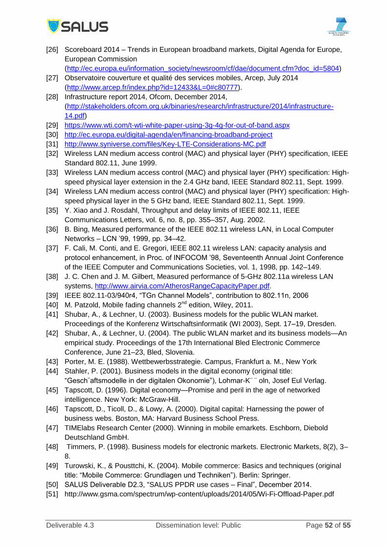
Deliverable 4.3 Dissemination level: Public Page 52 of 55
[26] Scoreboard 2014 – Trends in European broadband markets, Digital Agenda for Europe,
European Commission
(http://ec.europa.eu/information_society/newsroom/cf/dae/document.cfm?doc_id=5804)
[27] Observatoire couverture et qualité des services mobiles, Arcep, July 2014
(http://www.arcep.fr/index.php?id=12433&L=0#c80777).
[28] Infrastructure report 2014, Ofcom, December 2014,
(http://stakeholders.ofcom.org.uk/binaries/research/infrastructure/2014/infrastructure-
14.pdf)
[29] https://www.wti.com/t-wti-white-paper-using-3g-4g-for-out-of-band.aspx
[30] http://ec.europa.eu/digital-agenda/en/financing-broadband-project
[31] http://www.syniverse.com/files/Key-LTE-Considerations-MC.pdf
[32] Wireless LAN medium access control (MAC) and physical layer (PHY) specification, IEEE
Standard 802.11, June 1999.
[33] Wireless LAN medium access control (MAC) and physical layer (PHY) specification: High-
speed physical layer extension in the 2.4 GHz band, IEEE Standard 802.11, Sept. 1999.
[34] Wireless LAN medium access control (MAC) and physical layer (PHY) specification: High-
speed physical layer in the 5 GHz band, IEEE Standard 802.11, Sept. 1999.
[35] Y. Xiao and J. Rosdahl, Throughput and delay limits of IEEE 802.11, IEEE
Communications Letters, vol. 6, no. 8, pp. 355–357, Aug. 2002.
[36] B. Bing, Measured performance of the IEEE 802.11 wireless LAN, in Local Computer
Networks – LCN ’99, 1999, pp. 34–42.
[37] F. Cali, M. Conti, and E. Gregori, IEEE 802.11 wireless LAN: capacity analysis and
protocol enhancement, in Proc. of INFOCOM ’98, Seventeenth Annual Joint Conference
of the IEEE Computer and Communications Societies, vol. 1, 1998, pp. 142–149.
[38] J. C. Chen and J. M. Gilbert, Measured performance of 5-GHz 802.11a wireless LAN
systems, http://www.airvia.com/AtherosRangeCapacityPaper.pdf.
[39] IEEE 802.11-03/940r4, “TGn Channel Models”, contribution to 802.11n, 2006
[40] M. Patzold, Mobile fading channels 2nd edition, Wiley, 2011.
[41] Shubar, A., & Lechner, U. (2003). Business models for the public WLAN market.
Proceedings of the Konferenz Wirtschaftsinformatik (WI 2003), Sept. 17–19, Dresden.
[42] Shubar, A., & Lechner, U. (2004). The public WLAN market and its business models—An
empirical study. Proceedings of the 17th International Bled Electronic Commerce
Conference, June 21–23, Bled, Slovenia.
[43] Porter, M. E. (1988). Wettbewerbsstrategie. Campus, Frankfurt a. M., New York
[44] Stahler, P. (2001). Business models in the digital economy (original title:
“Gesch¨aftsmodelle in der digitalen Okonomie”), Lohmar-K¨ ¨ oln, Josef Eul Verlag.
[45] Tapscott, D. (1996). Digital economy—Promise and peril in the age of networked
intelligence. New York: McGraw-Hill.
[46] Tapscott, D., Ticoll, D., & Lowy, A. (2000). Digital capital: Harnessing the power of
business webs. Boston, MA: Harvard Business School Press.
[47] TIMElabs Research Center (2000). Winning in mobile emarkets. Eschborn, Diebold
Deutschland GmbH.
[48] Timmers, P. (1998). Business models for electronic markets. Electronic Markets, 8(2), 3–
8.
[49] Turowski, K., & Pousttchi, K. (2004). Mobile commerce: Basics and techniques (original
title: “Mobile Commerce: Grundlagen und Techniken”). Berlin: Springer.
[50] SALUS Deliverable D2.3, “SALUS PPDR use cases – Final”, December 2014.
[51] http://www.gsma.com/spectrum/wp-content/uploads/2014/05/Wi-Fi-Offload-Paper.pdf

Deliverable 4.3 Dissemination level: Public Page 53 of 55
[52] http://www.wifibroadband.org.uk/mvno_mno_isp.html
[53] http://www.wifibroadband.org.uk/ki_Carrier_Hampton_121011_public.pdf
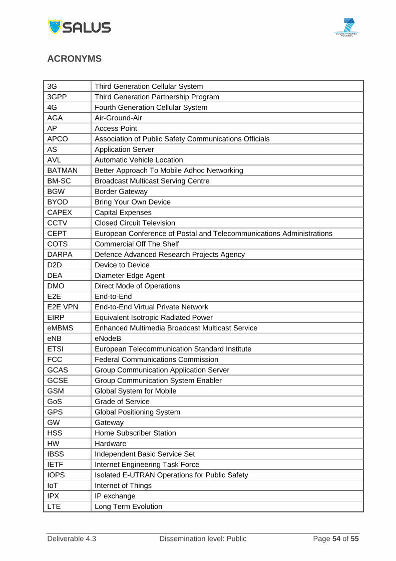
Deliverable 4.3 Dissemination level: Public Page 54 of 55
ACRONYMS
3G Third Generation Cellular System
3GPP Third Generation Partnership Program
4G Fourth Generation Cellular System
AGA Air-Ground-Air
AP Access Point
APCO Association of Public Safety Communications Officials
AS Application Server
AVL Automatic Vehicle Location
BATMAN Better Approach To Mobile Adhoc Networking
BM-SC Broadcast Multicast Serving Centre
BGW Border Gateway
BYOD Bring Your Own Device
CAPEX Capital Expenses
CCTV Closed Circuit Television
CEPT European Conference of Postal and Telecommunications Administrations
COTS Commercial Off The Shelf
DARPA Defence Advanced Research Projects Agency
D2D Device to Device
DEA Diameter Edge Agent
DMO Direct Mode of Operations
E2E End-to-End
E2E VPN End-to-End Virtual Private Network
EIRP Equivalent Isotropic Radiated Power
eMBMS Enhanced Multimedia Broadcast Multicast Service
eNB eNodeB
ETSI European Telecommunication Standard Institute
FCC Federal Communications Commission
GCAS Group Communication Application Server
GCSE Group Communication System Enabler
GSM Global System for Mobile
GoS Grade of Service
GPS Global Positioning System
GW Gateway
HSS Home Subscriber Station
HW Hardware
IBSS Independent Basic Service Set
IETF Internet Engineering Task Force
IOPS Isolated E-UTRAN Operations for Public Safety
IoT Internet of Things
IPX IP exchange
LTE Long Term Evolution

Deliverable 4.3 Dissemination level: Public Page 55 of 55
LPWA Low Power Wide Area
MANET Mobile Ad-hoc Network
MC Mission Critical
MCPTT Mission Critical Push-to-talk
MDM Mobile Device Management
MIMO Multiple Input Multiple Output
MME Mobility Management Entity
MNO Mobile Network Operator
MTC Machine Type Communications
MVNE Mobile Virtual Network Enabler
MVNO Mobile Virtual Network Operator
OLSR Optimized Link State Routing Protocol
OPEX Operational Expenses
PAMR Public Access Mobile Radio
PCRF Policy Control and Rating Function
PGW Packet Data Network Gateway
PMR Private Mobile Radio
PPDR Public Protection and Disaster Relief
ProSe Proximity Services
PTT Push-To-Talk
SGW Serving Gateway
SLA Service Level Agreement
SW Software
TCCA TETRA + Critical Communications Association
TDMA Time Division Multiple Access
TETRA Terrestrial Trunked Radio
TMO Trunked Mode Operation
UHF Ultra High Frequency
VHF Very High Frequency
VoLTE Voice over LTE
WLAN Wireless Local Area Network
Wi-Fi Wireless Fidelity
WRC World Radio-communications Conference