deh-230 entellisys low voltage switchgear system...
TRANSCRIPT


DEH-430Warnings, Cautions, and Notes as used in this publication
Warnings
WARNING! Warning notices are used in this publication to emphasize that hazardous voltages, currents, or other conditions that could cause personal injury exist in this equipment or may be associated with its use.
Warning notices are also used for situations in which inattention or lack of equipment knowledge could cause either personal injury or damage to equipment.
Cautions
CAUTION: Caution notices are used for situations in which equipment might be damaged if care is not taken.
Notes
NOTE: Notes call attention to information that is especially significant to understanding and operating the equipment.
This document is based on information available at the time of its publication. While efforts have been made to ensure accuracy, the information contained herein does not cover all details or variations in hardware and software, nor does it provide for every possible contingency in connection with installation, operation, and maintenance. Features may be described in here that are not present in all hardware and software systems. GE Consumer & Industrial assumes no obligation of notice to holders of this document with respect to changes subsequently made.
GE Consumer & Industrial makes no representation or warranty, expressed, implied, or statutory, with respect to, and assumes no responsibility for the accuracy, completeness, sufficiency, or usefulness of the information contained herein. No warrantees of merchantability or fitness for purpose shall apply.
Entellisys™, EntelliGuard™, and FlexLogic™ are trademarks of the General Electric Company.
Modbus RTU is a registered trademark of AEG Schneider Automation.
©Copyright 2005, 2007 General Electric
All Rights Reserved

How to contact us
Please have your Entellisys System Summary # and Sub # ready when calling. This information can be found on the Entellisys HMI on the System Health screen by clicking the Job Info button.
Post Sales ServiceGE Switchgear510 Agency RoadWest Burlington, IA 52655
Phone (toll free): 1-888-437-3765
Additional information:www.entellisys.com
For Option Upgrades and CPU Replacement needs only, e-mail us at [email protected].

Contents
1 System administrator roles and responsibilities1.1 Security Champion . . . . . . . . . . . . . . . . . . . . . . . . . . . . . . . . . . . . . . . . . . . . . . . . . . . . . . . . . . . . . . . . . . . . . . . . . . . . . . . . . . . . 7
1.1.1 System Maintenance . . . . . . . . . . . . . . . . . . . . . . . . . . . . . . . . . . . . . . . . . . . . . . . . . . . . . . . . . . . . . . . . . . . . . . . . . . . . . 7
2 Pre-programming settings prior to switchgear arrival
3 Commissioning the switchgear
4 User administration4.1 HMI User configuration . . . . . . . . . . . . . . . . . . . . . . . . . . . . . . . . . . . . . . . . . . . . . . . . . . . . . . . . . . . . . . . . . . . . . . . . . . . . . . . 13
4.1.1 Adding User Groups . . . . . . . . . . . . . . . . . . . . . . . . . . . . . . . . . . . . . . . . . . . . . . . . . . . . . . . . . . . . . . . . . . . . . . . . . . . . . 144.1.2 Adding Users . . . . . . . . . . . . . . . . . . . . . . . . . . . . . . . . . . . . . . . . . . . . . . . . . . . . . . . . . . . . . . . . . . . . . . . . . . . . . . . . . . . . 154.1.3 Resetting forgotten HMI passwords . . . . . . . . . . . . . . . . . . . . . . . . . . . . . . . . . . . . . . . . . . . . . . . . . . . . . . . . . . . . . . 16
4.2 Modbus® security . . . . . . . . . . . . . . . . . . . . . . . . . . . . . . . . . . . . . . . . . . . . . . . . . . . . . . . . . . . . . . . . . . . . . . . . . . . . . . . . . . . . 174.2.1 Control and settings passwords . . . . . . . . . . . . . . . . . . . . . . . . . . . . . . . . . . . . . . . . . . . . . . . . . . . . . . . . . . . . . . . . . . 174.2.2 HMI Roles . . . . . . . . . . . . . . . . . . . . . . . . . . . . . . . . . . . . . . . . . . . . . . . . . . . . . . . . . . . . . . . . . . . . . . . . . . . . . . . . . . . . . . . 18
5 Time synchronization5.1 Time synchronization configuration screen . . . . . . . . . . . . . . . . . . . . . . . . . . . . . . . . . . . . . . . . . . . . . . . . . . . . . . . . . . . . 225.2 Basic time sync configuration for stand-alone systems. . . . . . . . . . . . . . . . . . . . . . . . . . . . . . . . . . . . . . . . . . . . . . . . . 235.3 Time Sync configuration for multiple lineups . . . . . . . . . . . . . . . . . . . . . . . . . . . . . . . . . . . . . . . . . . . . . . . . . . . . . . . . . . . 245.4 Using an external time server . . . . . . . . . . . . . . . . . . . . . . . . . . . . . . . . . . . . . . . . . . . . . . . . . . . . . . . . . . . . . . . . . . . . . . . . . 255.5 Troubleshooting . . . . . . . . . . . . . . . . . . . . . . . . . . . . . . . . . . . . . . . . . . . . . . . . . . . . . . . . . . . . . . . . . . . . . . . . . . . . . . . . . . . . . . 26
6 Establishing communication to Remote HMIs6.1 Network re-configuration procedure . . . . . . . . . . . . . . . . . . . . . . . . . . . . . . . . . . . . . . . . . . . . . . . . . . . . . . . . . . . . . . . . . . 29
6.1.1 Prepare the local network. . . . . . . . . . . . . . . . . . . . . . . . . . . . . . . . . . . . . . . . . . . . . . . . . . . . . . . . . . . . . . . . . . . . . . . . 296.1.2 Connect to the local network. . . . . . . . . . . . . . . . . . . . . . . . . . . . . . . . . . . . . . . . . . . . . . . . . . . . . . . . . . . . . . . . . . . . . 30
6.2 Changing the CPU IP address . . . . . . . . . . . . . . . . . . . . . . . . . . . . . . . . . . . . . . . . . . . . . . . . . . . . . . . . . . . . . . . . . . . . . . . . . 306.3 Changing the local HMI IP address . . . . . . . . . . . . . . . . . . . . . . . . . . . . . . . . . . . . . . . . . . . . . . . . . . . . . . . . . . . . . . . . . . . . 316.4 Verify local communication to CPU . . . . . . . . . . . . . . . . . . . . . . . . . . . . . . . . . . . . . . . . . . . . . . . . . . . . . . . . . . . . . . . . . . . . 326.5 Network security/VPN device . . . . . . . . . . . . . . . . . . . . . . . . . . . . . . . . . . . . . . . . . . . . . . . . . . . . . . . . . . . . . . . . . . . . . . . . . 33
7 Remote HMI Software7.1 Installing and configuring remote HMI . . . . . . . . . . . . . . . . . . . . . . . . . . . . . . . . . . . . . . . . . . . . . . . . . . . . . . . . . . . . . . . . . 35
7.1.1 System Requirements . . . . . . . . . . . . . . . . . . . . . . . . . . . . . . . . . . . . . . . . . . . . . . . . . . . . . . . . . . . . . . . . . . . . . . . . . . . 357.1.2 Installation . . . . . . . . . . . . . . . . . . . . . . . . . . . . . . . . . . . . . . . . . . . . . . . . . . . . . . . . . . . . . . . . . . . . . . . . . . . . . . . . . . . . . . 36
7.2 Multiple lineups. . . . . . . . . . . . . . . . . . . . . . . . . . . . . . . . . . . . . . . . . . . . . . . . . . . . . . . . . . . . . . . . . . . . . . . . . . . . . . . . . . . . . . . 377.3 Configuring Lineups . . . . . . . . . . . . . . . . . . . . . . . . . . . . . . . . . . . . . . . . . . . . . . . . . . . . . . . . . . . . . . . . . . . . . . . . . . . . . . . . . . 38
7.3.1 Switching between lineups. . . . . . . . . . . . . . . . . . . . . . . . . . . . . . . . . . . . . . . . . . . . . . . . . . . . . . . . . . . . . . . . . . . . . . . 40
8 Settings files and offline system configuration8.1 Offline mode . . . . . . . . . . . . . . . . . . . . . . . . . . . . . . . . . . . . . . . . . . . . . . . . . . . . . . . . . . . . . . . . . . . . . . . . . . . . . . . . . . . . . . . . . 418.2 Viewing and comparing settings files . . . . . . . . . . . . . . . . . . . . . . . . . . . . . . . . . . . . . . . . . . . . . . . . . . . . . . . . . . . . . . . . . . 428.3 Writing settings to a live system. . . . . . . . . . . . . . . . . . . . . . . . . . . . . . . . . . . . . . . . . . . . . . . . . . . . . . . . . . . . . . . . . . . . . . . 438.4 Resetting the offline settings files to the current settings . . . . . . . . . . . . . . . . . . . . . . . . . . . . . . . . . . . . . . . . . . . . . . . 44
9 Sharing files across HMIs
Contents 5

9.1 Publishing shared files . . . . . . . . . . . . . . . . . . . . . . . . . . . . . . . . . . . . . . . . . . . . . . . . . . . . . . . . . . . . . . . . . . . . . . . . . . . . . . . . 459.2 Updating an HMI with shared files . . . . . . . . . . . . . . . . . . . . . . . . . . . . . . . . . . . . . . . . . . . . . . . . . . . . . . . . . . . . . . . . . . . . . 46
10 System archives10.1 Restoring an archive . . . . . . . . . . . . . . . . . . . . . . . . . . . . . . . . . . . . . . . . . . . . . . . . . . . . . . . . . . . . . . . . . . . . . . . . . . . . . . . . 4810.2 Creating an archive . . . . . . . . . . . . . . . . . . . . . . . . . . . . . . . . . . . . . . . . . . . . . . . . . . . . . . . . . . . . . . . . . . . . . . . . . . . . . . . . . 48
11 Feature options11.1 Viewing installed options . . . . . . . . . . . . . . . . . . . . . . . . . . . . . . . . . . . . . . . . . . . . . . . . . . . . . . . . . . . . . . . . . . . . . . . . . . . . 5111.2 Upgrading options . . . . . . . . . . . . . . . . . . . . . . . . . . . . . . . . . . . . . . . . . . . . . . . . . . . . . . . . . . . . . . . . . . . . . . . . . . . . . . . . . . 52
12 Preparing and configuring a replacement CPU12.1 Part I – Preparation for replacement of a CPU . . . . . . . . . . . . . . . . . . . . . . . . . . . . . . . . . . . . . . . . . . . . . . . . . . . . . . . . 5512.2 Part II – Replacing the CPU. . . . . . . . . . . . . . . . . . . . . . . . . . . . . . . . . . . . . . . . . . . . . . . . . . . . . . . . . . . . . . . . . . . . . . . . . . . 58
13 Other maintenance functions13.1 Viewing and updating circuit breaker names . . . . . . . . . . . . . . . . . . . . . . . . . . . . . . . . . . . . . . . . . . . . . . . . . . . . . . . . . 6513.2 Viewing and updating circuit breaker accessories . . . . . . . . . . . . . . . . . . . . . . . . . . . . . . . . . . . . . . . . . . . . . . . . . . . . 6613.3 Installing CPU firmware. . . . . . . . . . . . . . . . . . . . . . . . . . . . . . . . . . . . . . . . . . . . . . . . . . . . . . . . . . . . . . . . . . . . . . . . . . . . . . 6813.4 Viewing zone configuration . . . . . . . . . . . . . . . . . . . . . . . . . . . . . . . . . . . . . . . . . . . . . . . . . . . . . . . . . . . . . . . . . . . . . . . . . . 69
14 Administrator access to the operating system
6 Contents

1
1 System administrator roles and responsibilitiesThe Entellisys™ Low Voltage Switchgear system requires a System Administrator for oversight of critical functions. Those critical functions are described in this guide.
Chapter 1 provides an overview of the roles and responsibilities.
The following chapters describe how to perform the functions, in detail.
1.1 Security ChampionThe most important role of the System Administrator is to control the access to the system. There are several forms of access:
• HMI Login Access: Entellisys provides programmable permissions and passwords. The System Administrator determines who needs what permissions and assigns login names and passwords.
• Modbus® Settings and Control Access.
• Remote Access to the Switchgear over a company network.
Security Reminders• Limit the access level handed out to only the required permissions.
• Stress the importance of keeping passwords secret.
• If you believe passwords have been compromised, change them immediately.
• Always log out before leaving the local HMI, or leave the system logged in as Guest. Alternatively, the switchgear can be configured to automatically log out after a time period. (For details, on the Main Menu, click User Settings, and then click HMI Preferences.)
1.1.1 System Maintenance The System Administrator is also responsible for system maintenance as described in this document.
Security Champion 7

1
System administrator roles and responsibilities8

2
2 Pre-programming settings prior to switchgear arrival
Entellisys provides a method for users to work on the system settings before the switchgear arrives. Once the gear is installed and control power is applied, the saved settings can be written to the system.
To pre-program Settings, the “Entellisys Remote HMI – User Interactive version” must be purchased. GE will ship the Remote HMI software, System Administrator Manual (this manual), and a System Archive when the switchgear ships from the factory.
The following steps should be performed to begin pre-programming:
• Step 1: Install the “Entellisys Remote HMI – User Interactive version” software.
See Remote HMI Software on page 35 for instructions.
• Step 2: Install the System Archive provided by GE.
See Restoring an archive on page 48 for instructions.
• Step 3: Change to Offline Mode.
See Offline mode on page 41 for instructions and for offline mode capabilities.
• Step 4: Set User Settings.
See DEH-431 Entellisys Low Voltage Switchgear System User Manual.
• Step 5: Install and Commission the Switchgear.
See Commissioning the switchgear on page 11 for instructions.
• Step 6: Configure the System for Remote Communications.
See Establishing communication to Remote HMIs on page 29 for instructions.
• Step 7: Write saved Settings to System.
See Writing settings to a live system on page 43 for instructions.
9

22
Pre-programming settings prior to switchgear arrival10

3
3 Commissioning the switchgear
Installing and starting up the switchgear is an important event for the System Administrator. The following steps must be followed when commissioning the switchgear.
• Step 1: Reset Passwords.
See User administration on page 13.
• Step 2: Set User Settings.
See DEH-431 Entellisys Low Voltage Switchgear System User Manual.
• Step 3: Set Local HMI flags.
See HMI Roles on page 18.
• Step 4: Set System Time Synchronization.
See Time synchronization on page 21.
• Step 5: Configure System for Remote Communications.
See Establishing communication to Remote HMIs on page 29.
11

3
Commissioning the switchgear12

4
4 User administration
4.1 HMI User configurationThe Entellisys HMI requires a login name and password. This login sets the permissible actions for the session. Each user's permissions are programmable to provide flexibility. Only the Administrator can set permissions, login names, and passwords.
Since the HMI stores the user profiles locally, for systems with multiple HMIs, an individual user profile must be configured at each HMI.
Guest Login is the lowest level of access to the HMI and will assume the guest permissions at anytime a user has logged out. Guest is allowed “view only” access to all system status and breaker settings screens.
CAUTION: Enabling Group Permissions for features that allow the changing of settings and/or access to control functions must be restricted to accounts for qualified personnel only. As a reminder, users with such privileges will be presented with the following screen upon initial login:
Figure 4-1 Initial login Caution screen
Auto Logout
If the HMI is configured to logout a user after 30 or 60 minutes, the HMI will return to the default screen and login as a “guest” (Allowing view only access to the system). To configure or disable the auto logout, navigate to User Settings, then HMI Preferences and click on the General tab.
HMI User configuration 13

4
4.1.1 Adding User GroupsA Group defines the permission categories for a type or group of users. By default, there are 3 pre-configured groups - each with preset and fixed permissions. Moreover, the Administrator and Guest logins are preset. New user groups may be added to customize the permissions for a user.
Figure 4-2 Programmable permissions screen
New groups may be added and permissions may be assigned to the group or specific users in the group.
Add a group
1. On the Main Menu, click the User Administration button (Visible only by an Entellisys Administrator)
2. Click the desired user group to edit or click the Add Group button to define a new type of user.
3. Change the permissions by selecting the appropriate check boxes in the permission list.
User will be granted this permission.User will not have this permission.
4. The changes are immediately saved in the HMI
User administration14

4
4.1.2 Adding UsersAdd users under the appropriate group at each HMI. (Administrative user rights are required) Each individual that is expected to operate the system should be given their own account. There are three default users.
Guest: The guest login allows read-only access to all status and settings screens. The system defaults to guest level access as soon as someone logs out.
Operator: Individuals that require access to control breakers or acknowledge alarms and/or modify any of the breaker settings.
Administrator: Operator permissions plus access can backup and restore settings, change CPUs, create users and other administrative tasks.
Changing user permissions
Permissions may be changed on a user basis for all users added to new user groups. Operator and Administrator user permissions are fixed and can not be changed.
Figure 4-3 User Administration screen in the HMI
HMI User configuration 15

4
Adding new users1. On the Main Menu, click the User Administration button (Visible only by an Entellisys
Administrator)
2. Click the user group which the user will be added and click “Add User”
3. Update the contact information
4. In the Authentication box, Enter their login ID and password
5. Modify permissions if required (must create a new user group)
6. The changes are immediately saved in the HMI
To change a password1. On the Main Menu, click the User Administration button (Visible only by an Entellisys
Administrator)
2. Select the desired user group on the left-side pane. Expand the group by clicking the + symbol and click a user name
3. Enter the new password in the New Password field
4. Confirm your password by re-entering the new password in the Confirm Password field. Click OK to save your new password (or click Cancel to exit)
To verify the password change:1. Log out of the HMI by clicking the Login/Logout icon in upper right-hand corner
Figure 4-4 Login/Logout icon
2. Click once more to log back in and enter the new user name and password
4.1.3 Resetting forgotten HMI passwordsAdministrators have access permission to change passwords for all users in all groups.
NOTE: It is very important for the System Administrator to keep the Administrator password in a safe location. If the Administrator password is lost, a GE Field Service visit is required to restore the password.
GE offers an optional service to store the Administrator password at the request of customers. In the event the password is lost, GE can provide the password to the customer over the phone, without requiring a site visit .
Contact GE Post Sales Service for help (see How to contact us on page 2).
User administration16

4
4.2 Modbus® security
4.2.1 Control and settings passwordsThe CPUs require extra passwords to change settings (i.e., Short Time pickup delay setting) and to send commands (i.e., Open Breaker command). These passwords apply to all clients that access the Entellisys system through Modbus communications including the Entellisys HMI, SCADA, or Building Automation, etc.
NOTE: The system ships with default CPU Modbus Settings and Command passwords. The System Administrator should change these passwords for added security.
The HMI can be configured to transparently send the passwords whenever needed or it can be configured to require all users to re-enter the password when the action is attempted.
Figure 4-5 Modbus Security screen in the HMI
Modbus® security 17

4
To change the Settings and/or Command passwords1. On the Main Menu, click the Maintenance button. The button will only be displayed if access
is allowed with the current login permissions.
2. Click the Modbus Security tab. The Modbus Security screen has options to change both CPU A and CPU B Command and Settings passwords.
NOTE: It is recommended that the passwords in CPU A and CPU B be set to the same value.
3. Enter the new commands password in the New Password field
4. Re-enter the password in the Confirm Password field
5. Click the Change button to download the password
6. Select the desired Auto Send option
Indicates the Auto Send option will transparently send the password each time a command is sent to the CPUDisables the Auto Send option.The user will be prompted to enter the password (for the CPU that is currently the default) each time a command is sent
NOTE: For added security, it is recommended the Auto Send option be disabled. This will require an additional password to be entered each time a command is performed.
4.2.2 HMI RolesAn Entellisys system may have multiple HMI stations running. There are three different roles that the HMI software will perform. There are some functions that should be performed by one HMI only.
The Kiosked touchscreen HMIs are considered Local HMIs and can be configured as a local or a master HMI.
The “Local HMI” check box designates the near-gear or redundant HMI. When it is checked:
• The user can block breaker commands from other HMIs in the “Breaker Control” screen (See Chapter 3 in DEH-431 Entellisys Low Voltage Switchgear System User Manual)
• HMI uses port 503 for Modbus TCP/IP communication with CPUs
• “Master HMI” check box is cleared
• HMI updates time zone bias information of CPUs that reside in the same lineup whenever that information is adjusted
The “Master HMI” check box designates the primary in-gear HMI. When it is checked, the HMI have the functions of the Local HMI plus the ability to send alarm emails.
Remote HMI Role
The Remote HMI software which can be installed on a standard workstation or laptop. There are some minor differences between the Remote HMI and the Local HMI.
User administration18

4
• The Local and Master HMI controls are disabled• Does not send out email notifications for alarms
• Does not have ability to block breaker commands
• Uses port 502 for Modbus TCP/IP communication with CPUs
• Does not update time and time zone bias information of the CPUs
Communication restrictions
The CPUs can support up to 8 simultaneous communication ports for Modbus clients. Once the limit is exceeded, clients will be blocked until a port is free. The Local HMIs have special ports reserved for its use.
To set an Local HMI as a “Master”1. On the Main Menu, click the Maintenance button. The button will only be displayed if access
is allowed with the current login permissions.
2. Click the Modbus Security tab.
3. Select the Master check box as shown in Figure 4-5.
4. Click the OK button to save changes (or click Cancel to cancel changes).
Modbus® security 19

4
User administration20

5
5 Time synchronization
In the Entellisys System, events are generated by both the HMI and the CPU. When deciphering the event log, it is desirable that the date/time of all Entellisys devices are set from the same time reference. SNTP (Simple Network Time Protocol) is used to synchronize any number of Entellisys lineups. All systems must be networked together - either through the building LAN or through an isolated network.
Factory Default
Time Synchronization is not configured - See section 5.2 through 5.4 to configure
Synchronizing across multiple lineups
Additional lineups can be networked together and configured to reference the same time server. (See section 5.3)
It is possible to use another time server provided that:
• The Time Server supports passive SNTP
• The Time Server is connected to the HMI - CPU router
NOTE: If Entellisys is connected to the building LAN, a VPN must be used to prevent unwanted traffic on the Entellisys network.
Events
Time Server not Configured - logged when IP address of time source is set as 0 (initial condition).
Time Server Started - logged when time server is started at CPU and this CPU will be the synchronization point for all other devices.
Time Server Stopped - logged when time server is stopped at CPU.
Time Server Synchronization Successful - logged when CPU or HMI received it's first synchronization message for the time server. It is logged only on the first successful reception of synchronization message from the time server. As long as there were no time synchronization issues, this event will not be logged again.
21

5
5.1 Time synchronization configuration screenThe configuration screen in Figure 5-1 can be accessed by an administrator by clicking on the Maintenance submenu
Figure 5-1 (Time Synchronization tab
Time Synchronization Settings group box
The clock icon opens the Windows™ Date and Time Properties Applet.
Time Server Update group box
Unavailable if the IP address in the “Time Server” group box does not reference one of the CPUs in the current lineup or if the Remote HMI software has been installed.
If the Update Server’s Time Every 12 Hours check box is checked then the HMI is considered the “Master HMI” (see Figure 5-2) and will set the time on the CPU designated in the “Time Server IP Address” according to the HMI’s date and time.
Update Now Button will immediately synchronize the CPUs time with the HMI PC.
Time Server Group Box
Time Server IP Address: (Defaulted to 0.0.0.0) Enter a SNTP time server IP address here.
Enable HMI Time Synchronization: When checked, the PC clock on the HMI will be synchronized to the SNTP Timer Server designated in the “Time Server IP Address.”
Actual Time on Server: Only displayed when the “Time Server IP address” refers to a CPU in the current lineup.
Time synchronization22

5
5.2 Basic time sync configuration for stand-alone systemsThe local HMI - generally located in the gear - is designated as the master HMI. The master HMI will update the CPUA Real Time Clock (RTC) once every 12 hours. CPUA is also set as the SNTP server and will send SNTP messages to CPUB and all additional HMIsFigure 5-2 Time Synchronization factory configuration
Configure the Lineup as a stand-alone system
1. Identify the “Master HMI”. Go to the Modbus Security tab (Main Menu, Maintenance) and verify that “Master HMI” is checked
2. In the “Time Server” group box in the Time Synchronization tab (Main Menu, Maintenance), enter the IP address of CPU-A (The “Actual Time on Server” text box will update - see Figure 5-1)
3. At the master HMI, check “Update time server every 12 hours” and click the “Update Now” button
4. On all other Local HMIs, verify that the “Master HMI” check box is unchecked and “Enable HMI Time Synchronization” is checked and click the apply button (the apply button must be clicked to update the Windows Time Service with the new time server)
Change Time Zone or DST
1. On the “Master HMI,” login to the HMI as Administrator and click on the clock icon in the Time Synchronization tab (Main Menu, Maintenance) and change the time zone
2. Immediately close the HMI application and restart or allow the system to restart3. On the “Master HMI,” log back into the HMI as Administrator and navigate to Time Synchronization tab
(Main Menu, Maintenance) and click the “Update Now” button
NOTE: The time zone must only be changed on the “Master HMI” and the “Enable HMI Time Sync” option must not be checked.
Basic time sync configuration for stand-alone systems 23

5
5.3 Time Sync configuration for multiple lineupsAdditional lineups can be networked together and configured to reference the same time server.Customers who have 2 or more complete Entellisys lineups may network systems together to synchronize all lineups to approximately 8ms of each other.
Figure 5-3 Time Synchronization for multiple lineups
NOTE: All networked Entellisys lineups and associated HMIs should be set to the same time zone.
Configure an Entellisys lineup to synchronize with another Entellisys lineup
1. A “Master Lineup” must be designated and setup according to section 5.2 (All other lineups are considered “Client Lineups”)
2. All “Client Lineups” must also be first setup according to section 5.2 (This step must be done to ensure time zone information is correctly written to the “Client Lineups”)
3. Network the lineups together (See Network considerations below)4. On all client lineup HMIs, navigate to the Time Synchronization tab (Main Menu, Maintenance) and
• Change, if necessary, the “Time Server IP Address” to match the Time Server IP address of the “Master Lineup” (The “Actual Time on Server” text box MAY NOT update)
• Verify that the “Synchronize Server’s Time Every 12 hours” control is unchecked on all local HMI’s• Check the “Enable HMI Time Synchronization” • Click the apply button (the apply button must be clicked to update the Windows Time Service with the
new time server)
Networking considerations
• HMI and CPU IP addresses on all additional lineups must be changed to provide unique IP addressing (see Establishing communication to Remote HMIs on page 29)
Time synchronization24

5
• To verify each device is communicating, ping each device using a laptop connected to theCPU/HMI LAN
• If the lineups are in close proximity of each other a network cable can be routed between them (300ft is the maximum recommended length for Cat 5E cable)
• If existing network infrastructure is used, VPNs must be installed at each lineup (see Network security/VPN device on page 33.). It is recommended that a dedicated Control LAN be used to ensure the highest degree of accuracy
• The VPN must be configured to allow port 123 (SNTP uses port 123 - which is normally blocked on the VPN)
NOTE: If Entellisys is connected to the building LAN, VPNs must be used to prevent unwanted traffic on the Entellisys network.
5.4 Using an external time serverIf the time stamps on system events need to be synchronized to absolute time then a 3rd party time server may be used.
Time Server requirements:
• Time server that supports passive SNTP
• The time server is connected to the Entellisys VPN
Using an external time server 25

5
Figure 5-4 Time Sync w/ external SNTP time serverNOTE: GE cannot make any guarantees regarding time accuracy if the user decides to use a 3rd party SNTP time server OR uses a WAN or internet to connect two Entellisys systems.
Configuring Entellisys lineups to synchronize with external time source
In this configuration, neither a master HMI or Lineup are designated. Instead, each lineup should configured as a “Client Lineup.”
1. All lineups must first be setup according to section 5.2 (This step must be done to ensure time zone information is correctly written to lineup)
2. Network the lineups together (See Network considerations above)3. At all lineups, verify that the “Synchronize Server’s Time Every 12 hours” control is unchecked on all local
HMIs
4. On all HMIs, navigate to the Time Synchronization tab (Main Menu, Maintenance) and • Change, if necessary, the “Time Server IP Address” to match the 3rd party time server IP address (The
“Actual Time on Server” text box will NOT update)• Verify that the “Synchronize Server’s Time Every 12 hours” control is unchecked on all local HMI’s• Check the “Enable HMI Time Synchronization” • Click the apply button (the apply button must be clicked to update the Windows Time Service with the
new time server)
5.5 TroubleshootingCondition: After adding the time server IP address the actual address does not update with the current time
Problem: The time server is either not available or not communicating
Time synchronization26

5
Solution: There are many different reasons that this could occur.For single lineups: Verify that the IP address for the time server matches one of the CPUs
For multiple lineups coupled with closed circuit networks without a VPN:
• Verify that the IP addresses for each CPU and HMI are unique
• Verify that CPUs or HMIs can be pinged from either lineup
• Verify that the IP address entered matches the IP address entered on the “Master HMI” on the “Master Lineup”
For multiple lineups coupled with closed circuit networks with a VPN:
• Follow the same checklist for closed circuit networks without a VPN (above)
• Verify that port 123 is allowed in all VPNs
Condition: The event log shows time differences between HMI and CPU events
Problem: The HMI and CPU time clocks are different
Solution:
• On all HMIs: Verify that the time zones are all correct
• On all HMIs (except the “Master HMI”): Verify that the “Enable HMI Time Synchronization” is checked
• Restart the “Master HMI” and navigate to the Time Synchronization tab (Main Menu, Maintenance) and click the “Update Now” button
Condition: An HMI is not synchronized with the time server
Problem: The Windows Service may not be configured with the correct time server
Solution: Go to the Time Synchronization tab (Main Menu, Maintenance) and verify the correct IP address and click the Apply button
Troubleshooting 27

5
Time synchronization28

6
6 Establishing communication to Remote HMIs
The Entellisys system can be configured to communicate with up to 4 remote HMI PCs and 4 local HMI kiosked PanelC computers. The HMIs and CPUs all communicate through TCP/IP, and by default, these devices are configured with IP addresses that work together on the local network but will not communicate over a building network.
In general there are two methods to configure a Remote HMI workstation
• A separate dedicated network: A second network card is installed in the Remote HMI PCs which are connected to and configured for the Entellisys Network
• Utilize the building LAN: The Entellisys system is configured to communicate on the building LAN
NOTE: In either case, VPNs must be installed to protect the Entellisys network from network traffic, unauthorized access and viruses. Failing to do so will put the entire system at risk!
6.1 Network re-configuration procedureThe following procedure must be done at the dedicated Kiosked PanelC HMI either in or near the gear. The procedure must also be done before connecting to the building LAN. “Local” refers to Entellisys network in the gear which the HMIs or CPUs are connected.
6.1.1 Prepare the local networkStep 1: Since Entellisys components are not DHCP-compatible, each device must be assigned a static IP addresses which compatible on the company network
The number of IP addresses required depends on the number of HMIs. The following number of IP addresses is required:
• 2 addresses for CPU A and CPU B
• Addresses for all In-Gear and Near-Gear HMIs
• 2 addresses for the Juniper 5GT VPN
Step 2: Reset the CPU IP Addresses (See Changing the CPU IP address on page 30)
Step 3: Reset the local HMI IP Addresses (See Changing the local HMI IP address on page 31)
Step 4: Verify communication between the local HMIs and CPUs (See Verify local communication to CPU on page 32)
Step 5: Install and Configure a network security device such as a VPN/Firewall appliance (See Network security/VPN device on page 33)
Network re-configuration procedure 29

6
6.1.2 Connect to the local networkStep 1: Connect the Entellisys system to the company network via the VPN/Firewall appliance in the switchgear
Step 2: Verify communication between local HMI(s) and CPUs (See Verify local communication to CPU on page 32)
Step 3: Install Remote HMIs (See Remote HMI Software on page 35
Step 4: Verify communication between Remote HMI and CPUs
6.2 Changing the CPU IP addressTo change the CPU IP addresses1. Navigate to the Communication tab from the Main Menu, User Settings, HMI Preferences
2. Select either CPU A or CPU B by clicking the appropriate button.
3. Enter the new IP address. The IP address format is X.X.X.X where X is from 0 to 255.
Figure 6-1 CPU IP Address configuration screen on a Local HMI
NOTE: CPU IP address fields are read-only in the Remote HMI software. To configure Remote HMIs, see Configuring Lineups on page 38.
Establishing communication to Remote HMIs30
6
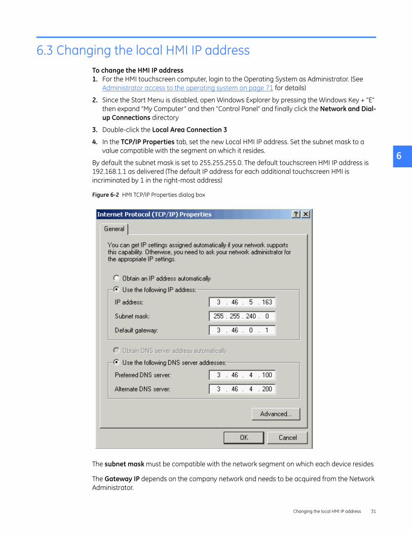
6.3 Changing the local HMI IP addressTo change the HMI IP address1. For the HMI touchscreen computer, login to the Operating System as Administrator. (See
Administrator access to the operating system on page 71 for details)
2. Since the Start Menu is disabled, open Windows Explorer by pressing the Windows Key + “E” then expand “My Computer” and then “Control Panel” and finally click the Network and Dial-up Connections directory
3. Double-click the Local Area Connection 3
4. In the TCP/IP Properties tab, set the new Local HMI IP address. Set the subnet mask to a value compatible with the segment on which it resides.
By default the subnet mask is set to 255.255.255.0. The default touchscreen HMI IP address is 192.168.1.1 as delivered (The default IP address for each additional touchscreen HMI is incriminated by 1 in the right-most address)
Figure 6-2 HMI TCP/IP Properties dialog box
The subnet mask must be compatible with the network segment on which each device resides
The Gateway IP depends on the company network and needs to be acquired from the Network Administrator.
Changing the local HMI IP address 31

6
6.4 Verify local communication to CPUThrough the HMI1. Navigate to the Communication tab from the Main Menu, User Settings, HMI Preferences
2. Click the Test Communication button to verify the communication status with the new IP address. It will take a few seconds to establish communication with the CPU.
3. If unable to connect, a dialog box will display. Click the Retry button to test communication again or click Cancel to exit.
4. The Communication status with the new IP address will display below the IP address edit dialog box.
For example: “CPU A: System Running OK” – Communication with new IP address is success.
“CPU B: System Unavailable” – Failed to communicate with new IP address.
Before installing the HMIGenerally, if the network and VPN/Firewall settings are correct, then the CPUs can be “pinged” utilizing the ping command that is installed with Windows.
1. Open a Dos Prompt: From the Windows Start menu, click on “Run” and type “CMD”
2. In the Dos window, type “Ping x.x.x.x” where x.x.x.x is the IP address of either CPU A
3. Repeat step 2 for CPU B
Figure 6-3 “Pinging a CPU’
Establishing communication to Remote HMIs32

6
6.5 Network security/VPN deviceNOTE: GE requires that your Entellisys Low Voltage Switchgear system must be equipped with a VPN/Firewall device if it is connected to a LAN that is also used for other purposes or any of the Remote HMIs are also connected to a LAN. Failure to do so could result in virus attacks or unauthorized access to the control and settings functions of the circuit breakers.
In addition to the standard username and password administrative functions for Entellisys, accessibility to control functions and parameter settings must be considered from the network point of view. The provisions for securing the network on which Entellisys communicates to HMI Control Stations and other SCADA systems depends greatly on how the network over which they communicate is configured.
GE provides a mechanical mounting assembly compatible with Juniper Networks NetScreen-5GT VPN/Firewall Appliance. Since configuration of the device is mostly dependent on the specific network architecture of the facility in which it is installed, please consult the NetScreen documentation for assistance in configuring this device, or contact your local IT department or network service provider.
GE recommends that the VPN/Firewall appliance be configured to only permit communications between the devices in the switchgear instrument compartment and the external devices that are intended to communicate with them.
Contact GE Post Sales Service for the latest VPN/Firewall appliance application and configuration guide. See How to contact us on page 2.
Network security/VPN device 33

6
Establishing communication to Remote HMIs34

7
7 Remote HMI Software
7.1 Installing and configuring remote HMIEntellisys Remote HMI software allows users to access the switchgear system from any desktop computer.
There are two versions of Remote HMI software:
• User Interactive version: provides programmable permission levels for all users from full “Administrator” access to view-only “Guest” privileges.
• Viewer version: limited to view-only “Guest” privileges. Login name and passwords are fixed.
The following steps are required to install and configure the Entellisys Low Voltage Switchgear – Remote HMI software:
7.1.1 System RequirementsPlease verify the target computer meets the requirements before Installing:
NOTE: ELVS HMI is compatible only with Windows Classic style for Windows XP system. This style can be set from the Display Properties dialog. Open the “Taskbar and Start menu” applet from the Windows XP Control Panel, select the “Start Menu” tab, check the “Classic Start menu” button and click Ok.
OS Microsoft Windows 2000, Service Pack 3/Windows XP, Service Pack 2
Processor Pentium III 1 GHz and 133 MHz processor bus, minimum
Memory 256 MB RAM, minimum
Storage device Hard disk drive 20 GB, minimum
Screen resolution 1024x768 in 256 colors, preferred
USB port One port required (USB 1.0 or 2.0)
Instances Entellisys supports up to 4 simultaneous Remote HMI connections
Entellisys version support
Entellisys 4.0 lineups only
Installing and configuring remote HMI 35

7
7.1.2 InstallationThe IP addresses of the system’s CPUs and the fixed IP for the Remote HMI station must be known before continuing.
Also, if the Remote HMI is connected to an open LAN, the Entellisys VPN must be installed in the gear and configured to allow the Remote HMI IP. (See Network security/VPN device on page 33)
Step 1: Set IP addresses, verify system communication
If the Remote HMI is being used to preconfigured gear using the HMI off-line mode, then go to Step 2, otherwise,
Remote HMIs will need some addition consideration to establish communication to the CPUs. Typically, computers that are connected to a network are configured to establish a TCP/IP address dynamically. However, the Entellisys devices are all static and some manual book keeping is required to ensure all devices on the Entellisys network are communication properly - see Changing the local HMI IP address on page 31
Step 2: Install Software
Insert the “Entellisys Remote HMI” CD and run the install program. Follow the on-screen installation wizard. Click Finish to complete the installation.
To start the Entellisys Remote HMI application, point to Start , select Programs, and then double-click Entellisys LVS HMI.
Step 3: License Software
The first time the Remote HMI program is launched, a window will display requesting an Activation code.
Figure 7-1 Remote HMI License Activation window
Remote HMI Software36

7
To obtain an Activation code, call GE at:
GE Switchgear – Post Sales Service510 Agency Road, West Burlington, IA 52655Phone (toll free): 1-888-437-3765
Please have the following information ready:
Entellisys System Identifier: Summary#, Sub#
• HMI Type: User Interactive or Viewer, on the blue title bar in Figure 7-1
• SITE CODE: from the activation window in Figure 7-1
• MID CODE: from the activation window in Figure 7-1
GE will verify that unused licenses of the desired version are available and will provide an Activation code for the software. Type in the Activation code and click Continue.
An example Activation code follows:
D11C8284-F54A0910-03D20031-B1ACADFA
Step 4: Configure Remote HMI to communicate to CPUs
After the software is licensed, the HMI will immediately open the HMI Preferences Screen. Click on Config Lineup and modify the “Default Lineup” with the IP addresses of the CPUs. (See Configuring Lineups on page 38 for details)
NOTE: When installing a Remote HMI prior to the switchgear arrival, this step cannot be performed. In this situation, a System Archive must be installed. See Restoring an archive on page 48 for instructions.
7.2 Multiple lineupsThe Remote HMI software allows the user to quickly navigate between multiple Entellisys 4.0 Lineups. It is important to note that HMI can only annunciate alarms from the current Lineup which the HMI is connected. Alarms from all other configured lineups are not recognized until the user connects to that lineup.
Highlights
• Available only on remote interactive or remote view HMI software
• View, edit and control up to 25 lineups
User Permissions
All users have permissions to add, change or delete Lineups
Offline Mode
If the Entellisys HMI software is configured for offline mode for any of the lineups, none of the configured lineups will connect. (See Offline mode on page 41)
HMI Events
Multiple lineups 37

7
When logging into the system, the HMI will log an event “Switched to <Lineup Name>.” The HMI will also log current time zones of the user’s PC running the Remote HMI software and the lineup CPUs.
NOTE: Time zone differences between a remote HMI and the lineup will cause timestamp differences between CPU and any local HMI events. Will not affect events on CPU
7.3 Configuring LineupsTo configure a Lineup, login to the HMI and from the main menu, select “HMI Preferences.” Click on the “Config Lineup”
Figure 7-2 HMI Preferences
To add a lineup1. Enter in the Lineup name (Must be unique and is limited to 30 characters)
2. Enter the Lineup Description (Limited to 250 characters)
3. Enter IP Addresses for both CPUA and CPUB (Must be unique)
4. Click the Startup Lineup to specify the default lineup
5. Click the “Add Lineup” button
To modify a lineup1. Click on the desired lineup in the list and the Name, Description and IP addresses will
populate with the lineup information - edit the information
Remote HMI Software38

7
2. Select “Update Lineup”To Delete a lineup1. Click on the desired lineup in the list and the Name, Description and IP addresses will
populate with the lineup information
2. Select “Delete Lineup” (The current lineup and startup lineup cannot be deleted)
The Startup LineupThe Startup Lineup is the default lineup which the HMI connects to each time the Remote HMI software is started
Configuration file upload
After either changing the default lineup or when connecting to an Entellisys Lineup for the first time, the HMI will attempt to connect and upload all HMI files from the CPUs of the respective lineup. (See figure 7-3) If the CPUs are unavailable, the lineup will still be entered and HMI will try again when the user selects the HMI from the “Select Lineup” screen. If there is a mismatch, the user will be prompted to either update the HMI or do nothing.
Figure 7-3 HMI file mismatch dialog
If the Entellisys system was configured in offline mode, do not select “Update HMI.” See section Writing settings to a live system on page 43 for details on uploading settings to the CPU.
NOTE: The order in which lineups appear in the “Select Lineup” screen is fixed to the order in which they were added into the HMI.
Configuring Lineups 39

7
7.3.1 Switching between lineupsThe Entellisys LVS Remote HMI lets you configure up to 25 lineups. Click on the select lineup button (in HMI title bar) to view the dashboard screen as shown below. The name of the lineup that the HMI is currently connected to will remain in the title bar until another lineup is selected.Figure 7-4 Select Lineup Menu
The Dashboard displays all the configured lineups. To switch to a different lineup, simply click on the Lineup.
Connecting to a lineup for the first time
The HMI will prompt to download files from the CPU for selected lineup and will display the default HMI screen for that lineup. All subsequent connections to Lineup, the HMI will use the local files stored on the HMI. The HMI will also prompt for a download if the CPU has been updated from another HMI.
Offline HMIs
If the Remote HMI is off-line (See Offline mode on page 41), lineup communication is not tested. However, the user can still add, edit, delete and switch between lineups. The HMI will use local HMI files if available.
Communication status LED
While in the “Select Lineup” screen, the communication is tested for each of the configured lineups and the status is indicated by the communication status LED according to colors below:
• Green - both CPUs are communicating with the HMI
• Yellow - only one of the CPUs is communicating with the HMI
• Red - neither CPU is communicating with the HMI
• Grayed-out - when the CPU is incompatible or the HMI as been set to off-line by the user and does not attempt to establish communication to any of the lineups
Remote HMI Software40

8
8 Settings files and offline system configuration
All system settings are recorded locally in “Settings” files. These files are updated each time a setting is modified and automatically updated every 30 minutes.
NOTE: Both CPUs must have the same configuration and settings at all times, otherwise unpredictable system behavior could occur. Every 30 minutes the system compares the settings between the CPUs. If a mismatch in settings between CPUs does occur, an event will be generated. A mismatch should be correctly immediately.
8.1 Offline modeThe HMI has a special offline mode. Offline mode disconnects the HMI from a live system and allows users to modify and save settings. Later, once reconnected to a live system, these saved settings can be written to the system.
The following operations are permitted in offline mode:
• User Settings activities
• Maintenance activities
• User Administration
Another convenience offline mode provides is the ability to work on protection settings prior to the arrival of the switchgear. See Commissioning the switchgear on page 11 for more details.
Figure 8-1 Settings File screen
Offline mode 41

8
To enable or disable offline mode1. On the Main Menu, click the Maintenance button. The button will only display if
Maintenance access is allowed with the current login permissions.
2. On the Maintenance screen, click the Settings File tab.
3. Select the Work Offline check box to change to offline mode. This can be found in the lower right-hand corner in Figure X (chapter 2.1). [dk: no section 2.1?]
HMI will go into offline mode and disconnect from the live system.HMI will connect to the live system.
A message on the status bar will indicate that the application is in offline mode.
The first time offline mode is enabled, a new set of settings files will be created as follows: Offline(ELVS_A).fbs and Offline(ELVS_B).fbs.
4. Click Load to ensure the desired files are loaded for offline work. If the Load button is grayed out, the highlighted file is already loaded.
NOTE: If the state of the offline settings files is unknown, it is recommended to reset the offline settings files to the current settings. See Chapter 2.4. [dk: there is no section 2.4?]
Changes made during offline mode• User Settings and Maintenance changes are automatically saved to the active settings file
loaded.
• User Administration changes can be viewed under User Administration only.
8.2 Viewing and comparing settings filesThe HMI can display the settings associated with a particular settings file. To view any settings file, click the filename in the right-side pane, click Load, and the settings will display.
As mentioned in Chapter 2, it is important to keep the settings in both CPUs consistent. The HMI can compare two settings files and highlight differences.
To compare two settings files1. On the Main Menu, click the Maintenance button. The button will only display if
Maintenance access is allowed with the current login permissions.
2. On the Maintenance screen, click the Settings File tab.
3. Select two files to compare (e.g., ELVS_A and ELVS_B). To select two files, hold down the Shift key and click both file buttons. Once two files are selected the compare button will be enabled.
4. Click the Compare button. The differences between the two files will be highlighted.
Settings files and offline system configuration42

8
Figure 8-2 Settings file compare screen
8.3 Writing settings to a live systemTo make the offline settings permanent in the live system1. On the Main Menu, click the Maintenance button. The button will only display if access is
allowed with the current login permissions.
2. On the Maintenance screen, click the Settings File tab.
3. Verify the HMI is connected to the system (clear the Work Off Line check box).
4. Select the offline settings to download. Once selected, the settings values will display on the screen.
5. Click Write To. The screen in Figure 8-3 will display.
Writing settings to a live system 43

8
Figure 8-3 Write Settings screen
6. Select the CPU name to and click download.
A Red CPU indicates that it is not currently communicating and cannot be written.
NOTE: It is recommended that users only perform Write To when both CPUs are communicating to avoid a mismatch in settings when the second CPU starts communicating.
7. Click the Write button to send the settings to the selected CPU.
8. Repeat steps 5 to 7 for the second CPU.
8.4 Resetting the offline settings files to the current settingsIt may be desired to reset the offline settings files to the current settings.
To copy current settings to the offline settings files1. On the Maintenance screen, click the Settings File tab, and then select the settings to copy.
2. Click the Write To button.
3. Select the offline files as the device to write to.
4. Click the Write button.
Settings files and offline system configuration44

9
9 Sharing files across HMIs
The HMI provides a tool for the System Administrator to distribute files across all HMIs.
Figure 9-1 HMI Shared Files screen
9.1 Publishing shared filesPublishing shared files should be done whenever the following changes are made. (Other HMIs must be updated manually, see Updating an HMI with shared files.
• Oneline, Elevation, or Control Panel screens
• Alarm configuration
• Circuit breakers are added to the system or circuit breaker maintenance is updated
• Advanced protection zones, tiers, or topologies change
• User configurations and passwords are not updated
To publish shared files for other HMIs to retrieve1. On the Main Menu, click User Settings.
2. Click HMI Preferences.
3. In the HMI Preferences dialog box, click General.
4. In the HMI Shared File dialog box, click the Update CPUs button. Only the Administrator will have access perform this task. The button will be grayed out if the current session does not have Administrator permissions.
NOTE: The HMI will only update files which are newer than those on the CPU.
Publishing shared files 45

9
NOTE: Pop-up dialog boxes shall appear (one per CPU) confirming files are successfully written to each CPU. Should any file fail to publish, an appropriate pop-up dialog box shall appear identifying the file(s) and CPU to which the publish was not successful.
9.2 Updating an HMI with shared filesTo obtain the custom files an Administrator has published1. On the Main Menu, click User Settings.
2. Click HMI Preferences.
3. In the HMI Preferences dialog box, click General.
4. Click Update HMI.
5. Click Yes in the confirmation dialog box to proceed by loading the shared files. (Or click No to cancel the operation.)
6. Once the file transfer is complete, a list of transferred file names is displayed. Click OK to complete the process.
Sharing files across HMIs46

10
10 System archives
A System Archive is a snapshot of the system's custom screens, configuration, and optionally the event logs, fault reports, and waveforms. The archive is used to reconfigure a system, putting it back to a known state. It is important to have a valid System Archive at all times.
An archive is created and shipped to the System Administrator when the switchgear ships from the factory. The archive may be installed in a Remote HMI application allowing users to pre-program protection settings prior to the switchgear arrival.
Archives are recommended at the following events:
• At switchgear startup, once the system settings have been programmed and tested.
• Periodically throughout the life of the switchgear – for example prior to summer shutdown each year.
Figure 10-1 Archive screen
47

10
10.1 Restoring an archiveTo install or restore an archive from a USB flash memory device1. On the Main Menu, click the Maintenance button. The button will only be displayed if access
is allowed with the current login permissions.
2. Click the Backup/Restore Archive tab.
3. Click Restore Archive From USB. The system will search for an active USB drive. If not found, a dialog box stating “Can't find any USB drive” will display.
4. Select the directory where the Archive is located. An example of an Archive Directory is as follows: ELVSArchive_12212004_180230. The directory name contains the date and time the archive was taken.
5. Once a valid Archive directory is selected, the Restore button will be enabled. Click the Restore button.
6. A confirmation dialog box will display. Click Yes to proceed.
7. The Archive is now restored. Click the Close button to exit. The system will automatically eject the USB device.
8. Click the “Settings File" tab and select "(offline)ELVS_A"
9. Click "Write To" button and select "CPU A" and finally click the “Write” button
10. Repeat for CPU B
11. Click on the General button (Main Menu/User Settings/HMI Preferences) and click update CPU and restart the HMI
The following files are restored in the process:
• Setting Files
• Multipoint Configuration and Breaker Settings
• One Line, Elevation Files, and Control Panel screen files
• Event Logs (optional)
• Fault Reports (optional)
• Waveforms (optional)
10.2 Creating an archiveTo create an archive and save it to a USB flash memory device1. On the Main Menu, click the Maintenance button. The button will only be displayed if access
is allowed with the current login permissions.
2. Click the Settings File tab and select “ELVS_A” and click “Load”
3. After it’s done, click “Write To” and select "(OFFLINE) BOTH CPU's" and click the “Write" button
4. Click the Backup/Restore Archive tab.
5. Click the Backup Archive to USB button.
6. Select the files to backup in the Archive Files Selection dialog box as in Figure 10-2.
System archives48

10
NOTE: The log files may be very large in size and are not required to recreate a system. It is recommended to clear all three log files.
Figure 10-2 Archive File Selection screen
7. Once the desired files are selected, click OK to proceed (or click Cancel to exit).
8. Insert the USB flash memory device into the USB port.
9. Select the USB drive. Once a valid drive is selected, the Backup button is automatically enabled.
10. Select the folder where you want the archive to be created.
11. Click the Backup button. A subfolder with the current date and time stamp is automatically created. On successful completion of the backup, a message will display: “Backup has been taken in the following directory <subfolder name>. Please Close the dialog”.
Creating an archive 49

10
System archives50

11
11 Feature options
The Entellisys Low Voltage Switchgear system has many features available through software upgrades.
11.1 Viewing installed options1. On the Main Menu, click the Maintenance button. The button will only be displayed if access
is allowed with the current login permissions.
2. Click the Options tab to view current installed software options as shown in Figure 11-1.
Figure 11-1 Installed Options screen
Viewing installed options 51

11
11.2 Upgrading optionsThe process for upgrading features is as follows:
Step 1: Request an Upgrade through HMIThe Administrator must make a request at the HMI. The HMI saves required information (*.dat file) to a USB flash memory device and must be sent to GE for creating a new encrypted “option string” which contains all existing and newly purchased features.
To request an upgrade1. Insert the USB device into the HMI USB port. For Touchscreen HMIs, this port is accessed
from the front of the switchgear, behind the small door in the bottom right corner of the HMI.
2. On the Main Menu, click the Maintenance button. The button will only be displayed if access is allowed with the current login permissions.
3. Click the Upgrade Options tab, as shown in Figure 11-1.
Figure 11-1 Upgrade Options screen
4. In the “Request Option Upgrade” group, click the Save Request To USB button.
5. Select a valid USB drive. Once a valid drive is selected, the Save button is automatically enabled.
6. Enter a File Name in the dialog box.
7. Click the Save button. A message will confirm the “Option String successfully saved into file (directory path).” Acknowledge the message dialog box.
Feature options52

11
Step 2: Send Request to GE with Data from USB To place order, contact GE Post Sales Support (see How to contact us on page 2).
GE will request the following information:
• Entellisys System Identifier: Summary#, Sub#
• HMI Upgrade request information saved on the USB flash memory device (*.dat file)
• New options requested
Some features are simple to add, and can be upgraded by the System Administrator. Other features require more programming and potentially onsite installation/testing to ensure system performance. This will be explained when the order is placed.
Step 3: Get new Option String from GEGE will either mail or e-mail the new option string (*.dat file). Copy the new option string to a USB flash memory device.
Step 4: Install the Upgrade Follow the procedure below to install the feature upgrade option string:
1. Insert the USB flash device into a USB port. For Touchscreen HMIs, this port is accessed from the front of the switchgear, behind the small door in the bottom right corner of the HMI.
2. On the Main Menu, click the Maintenance button. The button will only be displayed if access is allowed with the current login permissions.
3. Click the Open Options String File button in the Upgrade Option String group.
4. In the “Browse CPU Option File” dialog box, select the Option string file (file extension is .dat).
5. Click Open. A dialog box stating “Option String successfully read” will display. Acknowledge the dialog box.
6. After successful reading of the option string, the Write to Both CPUs and Reboot button will automatically be enabled. Click the Write to Both CPUs and Reboot button. A confirmation message will display stating that “After Option string loading started, you can't abort it. Are you sure you want to proceed it”.
7. Click Yes to proceed (or click No to cancel option upgrade). The “Loading Option String” status will display.
8. Verify the feature upgrades are installed. On the Maintenance screen, click the Options tab. Select the Line-up Options and Per Breaker Options items.
Upgrading options 53

11
Feature options54

12
12 Preparing and configuring a replacement CPU
This procedure discusses the steps to be performed within the HMI when replacing a CPU. The actual mechanical replacement procedure is located in the DEH-234 Entellisys Low Voltage Switchgear Device Replacement Guide, Chapter 1, “Replacing a CPU chassis”. Please read these instructions thoroughly prior to beginning the replacement.
NOTE: At least one CPU must be working. Factory must generate a new option string with the serial number of the new CPU. The new option string must be present before starting this wizard - which can either emailed or a USB must be shipped from the factory.
If both CPUs are down, GE Factory services must be called to restore CPUs
12.1 Part I – Preparation for replacement of a CPUStep 1
• On the Maintenance screen, click the Replace CPU tab. Click Perform Preparation. This will bring up the Step 1 – Select CPU dialog box. Select which CPU is to be replaced.
Figure 12-1 Step 1 – Select CPU dialog box
Part I – Preparation for replacement of a CPU 55

12
Step 2
• After clicking Next , the following instructions will display:
Figure 12-2 Read Option String dialog box
• Save the old Option String to the memory stick and click Next:
Figure 12-3 Browse CPU Option String File dialog box
Preparing and configuring a replacement CPU56

12
Step 3 and 4
• If the replacement CPU is onsite, the serial number of the replacement cpu must be entered so the option string can be generated by the factory.
• Click Ordering New if the CPU is not onsite. An option string will be generated for the new replacement CPU by the factory.
Figure 12-4 Step 3 – CPU Serial Number dialog box
Figure 12-5 Step 4 – Preparation Finished dialog box
The option string, serial number, and IP address of both CPUs are now saved to the USB drive.
Part I – Preparation for replacement of a CPU 57
12
12.2 Part II – Replacing the CPUThis wizard assists in replacing the CPU and modifying the IP Address Configuration, Firmware, Option String, Settings, and CPU Commission options.
Step 0
• Ensure that there is a valid option string on a USB, the replacement hardware is ready, the serial numbers and IP addresses of both CPUs are known.
• Disconnect Entellisys switchgear from all external networks at the HMI switch.
• Navigate to the Replace CPU tab in the Maintenance dialog box, click Perform Replacement to begin the CPU replacement wizard.
• Run steps 1-9 on the Local HMI.
NOTE: If Entellisys has not been disconnected from any external ethernet networks, the replacement process may fail.
WARNING! If steps are skipped but have not been completed by re-starting the wizard, the replacement CPU may not operate properly.
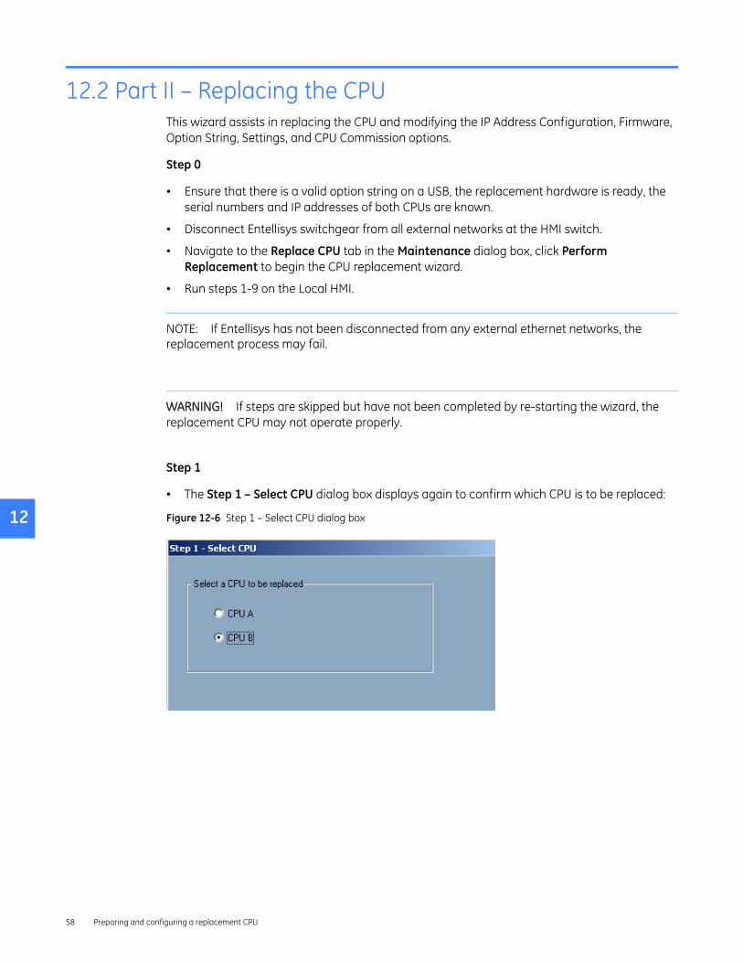
Step 1
• The Step 1 – Select CPU dialog box displays again to confirm which CPU is to be replaced:
Figure 12-6 Step 1 – Select CPU dialog box
Preparing and configuring a replacement CPU58
12
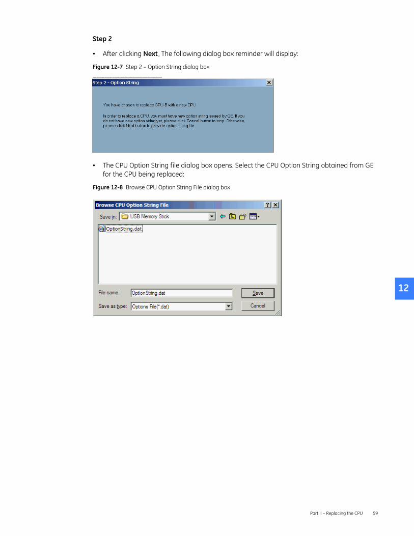
Step 2
• After clicking Next , The following dialog box reminder will display:
Figure 12-7 Step 2 – Option String dialog boxdddddddddddddddddddddddddddddddddddddddddddddddddddddddddddddddddddddddddddddddddddddddddddddd
• The CPU Option String file dialog box opens. Select the CPU Option String obtained from GE for the CPU being replaced:
Figure 12-8 Browse CPU Option String File dialog box
Part II – Replacing the CPU 59

12
Step 3
• After selecting the option string, the Step 3 – Set Default IP dialog box will display as shown below. This will change the configured address within the HMI to the default address of a new CPU in preparation for communicating with it in Step 4.
NOTE: If the IP Address of the CPU has already been set or if the CPU is not functioning, select Skip This Task and click Next . Otherwise, click Next and the CPU IP address will be changed. The current IP configuration will be stored before it is changed.
Figure 12-9 Step 3 – Set Default IP dialog box
• A series of messages will display confirming the status of changes as they are being made.
NOTE: After performing this step the CPU may be powered down and physically swapped out. Please refer to DEH-234 Entellisys Low Voltage Switchgear Device Replacement Guide, Chapter 1, “Replacing a CPU chassis”, for this procedure prior to proceeding to the next section.
Preparing and configuring a replacement CPU60

12
Step 4
• Apply power to the new CPU and allow 2 minutes for the device to self-initialize prior to performing Step 4. If the new CPU is known to already have an IP address as specified in the Step 4 dialog box, select the Skip This Task check box prior to clicking Next . Otherwise, leave the check box cleared and just click Next .
Figure 12-10 Step 4 – Set Original IP dialog box
• A confirmation dialog box will display asking for confirmation that the old CPU has been replaced and the new CPU is installed and has been powered on for at least 2 minutes.
Figure 12-11 Entellisys LVS HMI dialog box
• Several progress messages will display prior to the Step 5 dialog box as shown below. In this step, the HMI will read the firmware versions of each CPU and verify that they match.
Part II – Replacing the CPU 61

12
Step 5
NOTE: If there is a mismatch in the version numbers, clicking next will download the correct firmware from the other CPU before continuing to the next step.
Figure 12-12 Step 5 – CPU Firmware dialog box
Step 6
• Click Next to update the option string. This task may be skipped by selecting the check box if the new CPU is known to already have the correct option string.
Figure 12-13 Step 6 – Update Option String dialog box
Preparing and configuring a replacement CPU62

12
Step 7
• The option string will be written to the CPUs, after which they will automatically reboot. After the reboot is complete, the dialog box for Step 7 will be displayed to update the settings of the new unit. The option to skip the task is available if this has already been done.
• HMI will now copy both factory configuration and user settings to the new CPU.
Figure 12-14 Step 7 – Copy Setting dialog box
Step 8
• Click Next to commission the new CPU and activate all of the relaying and protection algorithms in the unit.
Figure 12-15 Step 8 – Set CPU Commission dialog box
Part II – Replacing the CPU 63

12
Step 9
• Finally, in step 9, the option string will be downloaded into the new CPU. Click the Finish button to complete the process.
Figure 12-16 Step 9– Update Option String dialog box
The replacement wizard is now complete.
Preparing and configuring a replacement CPU64

13
13 Other maintenance functions
13.1 Viewing and updating circuit breaker namesThe HMI provides a tool to change the circuit breaker names corresponding to their location in the switchgear.
To change the circuit breaker names1. On the Main Menu, click the Maintenance button. The button will only be displayed if access
is allowed with the current login permissions.
2. Click the Breaker Names tab. A table will display as shown as in Figure 13-1.
Figure 13-1 Breaker Names screen
• Breaker ID: Unique identifier for the circuit breaker. This is set by GE and cannot be changed.
• Breaker Name: Unique name given to a circuit breaker (16 alphanumeric characters). This may be set in the factory if information is provided from the customer. Otherwise, it should be updated for ease of use with selection boxes.
• Short Name: Unique short name given to a circuit breaker (8 alphanumeric characters). This field is currently not used.
Viewing and updating circuit breaker names 65

13
• Compartment#: Unique identifier for the location of the circuit breaker in the switchgear. The Compartment# is set by the factory upon shipment to the customer and cannot be changed. It is often included on nameplates on the switchgear.
3. Click the OK button to keep changes (or click Cancel to exit the screen without saving).
NOTE: Changes to circuit breaker names will not be reflected on the custom Oneline screen. Contact GE Post Sales Support for details about updating to the Oneline screen (see How to contact us on page 2).
13.2 Viewing and updating circuit breaker accessoriesThe HMI displays the circuit breaker status for each circuit breaker in the system. To display the proper circuit breaker status, the installed accessories must be known.
The following is affected by the installed accessories:
• Breaker Racking Position status is available only if the position switch accessory is installed.
• Electrically Locked Out status is available only if either the Bell-Alarm or Network Interlock accessory is present.
• Closing Spring Status is available only if the Electric Operated accessory is present.
Additionally, the Breaker Control relies on the electric operated circuit breaker accessory. The remote control functions will be limited by the presence of the electrically operated accessory.
The following functions in the HMI Breaker Control are affected:
• Open Breaker function is displayed only if the electrical operated accessory is present.
• Close Breaker function is displayed only if the electrical operated accessory is present.
• Trip Breaker is NOT affected.
GE configures the proper circuit breaker accessories upon shipment of the switchgear. However, if the accessories change or if different circuit breakers are exchanged, the accessories must be updated, otherwise the status might not be correct.
Other maintenance functions66

13
To view or change the circuit breaker accessories1. On the Main Menu, click the Maintenance button. The button will only be displayed if access
is allowed with the current login permissions.
2. Click the Accessories tab. A table will display as shown as in Figure 13-2.
Figure 13-2 Breaker Accessories screen
• Breaker Name: Unique name given to a circuit breaker.
• Electric Operated: Accessory allows the circuit breaker to be opened, closed, and charged remotely. The check box should be selected if this accessory is present.
• LockOut: Circuit breaker contains either a bell alarm lockout accessory to prevent reclosing after tripping, or a network interlock accessory to prevent closing during automatic throw over. The check box should be selected if this accessory is present.
• Position Switch: Circuit breaker contains an accessory that provides remote monitoring of the position of the circuit breaker during rack-in and rack-out. The check box should be selected if this accessory is present.
3. Click the OK button to keep changes (or click Cancel to exit the screen without saving).
Viewing and updating circuit breaker accessories 67

13
13.3 Installing CPU firmwareThe HMI provides a tool to upgrade software (or firmware) in the CPUs.
CAUTION: Downloading new firmware to a CPU will erase all previous settings in the unit. See Writing settings to a live system on page 43 for instructions on restoring CPU settings.
NOTE: Both CPUs must have the same firmware version loaded.
Figure 13-3 CPU Firmware Download screen
To download new firmware to the CPUs1. On the Main Menu, click the Maintenance button. The button will only be displayed if access
is allowed with the current login permissions.
2. Click the CPU Firmware tab.
3. Click the Browse button to select a CPU firmware file.
4. Locate the CPU firmware (ELVS_CPU.BIN) file and click the Open button.
5. If the selected file is valid, the Firmware Info will display and Download to CPU A and Download to CPU B buttons will be enabled. Click the corresponding button for the CPU to download the firmware.
Other maintenance functions68

13
13.4 Viewing zone configurationThe Zone Configuration screen gives an overview of the global zone configuration and also for each protection function (Multi Source Ground Fault, Bus Differential, and Zone Selective Interlock).
See DEH-431 Entellisys Low Voltage Switchgear System User Manual, Chapter 6 (Zones, buses, and topologies) for details.
Viewing zone configuration 69

13
Other maintenance functions70

14
14 Administrator access to the operating system
Each Entellisys Touchscreen HMI computer has been configured to prevent direct access to the computer's operating system. Special user permissions are required to exit the HMI application. If exited, the only function allowed is to restart the computer.
For special cases when access to the computer is required, there is a way for the Entellisys System Administrator to logon to the operating system as an Administrator. This will give the user full access to the computer. It is strongly recommended that the System Administrator limit knowledge of this ability to prevent unauthorized access.
Administrative access to the operating system of an HMI Touchscreen Computer
1. Press Ctrl+Alt+Delete. A Windows Security dialog box will display
2. Press the Logoff button
3. Constantly press the Shift key until the login dialog box “Login On Windows as” displays
4. Enter User Name as “Administrator”
5. Enter Password as “gestart”
6. Press the OK button
Restarting the PanelC
1. Press Ctrl+Alt+Delete and a Windows Security dialog box will display
2. Press the Shutdown button
3. Select Restart from the pull down and click ok
CAUTION: The system should never be left unattended in this state since unauthorized access could result in damage to the computer image requiring a new image to be loaded. Always restart the computer to revert to the default state.
71

14
Administrator access to the operating system72