degradation study of pressurized solid oxide fuel cells
TRANSCRIPT

Degradation Study of Pressurized Solid Oxide Fuel Cells
Dissertation Proposal:By
Nathanael Royer
Committee Members:Dr. Dustin McClarty, Chair
Dr. Jacob Leachman Dr. M. Grant Norton

Outline
• Background
• Significance and Objectives
• Accomplishments & Work in Progress
• Remaining/ Future Work
• Timeline

Background
Why Solid Oxide Fuel Cells?
http://www.fuelcell.no/fuel_cell_types_sofc_eng.htm

Solid Oxide Fuel Cells: Solid State Energy Conversion
• Solid oxide fuel cells are devices that convert hydrocarbon fuels directly into electricity through electrochemical reactions.
• They are distinguished from other types of fuel cells by the use of a solid ceramic electrolyte, typically Yttria stabilized Zirconia.
• Electrochemical reactions occur according to:
Anode:2 H2 + 2 O-2→ 2 H2O + 4 e-
Cathode:O2 + 4 e- → 2 O-2

Efficiency• Solid Oxide Fuel Cells (SOFC’s) convert fuel to
electricity directly through electrochemical reactions.
• Maximum efficiency not limited by Carnot cycle limitations. [1]
• Theoretical Max efficiency fuel to electricity of pure hydrogen/oxygen fuel cell at room temperature is 83%. [CITE]
• SOFC’s in practice reach efficiencies exceeding 50%, or with heat capture efficiency can exceed 80% [3]
[1] J. A. Caton, AN INTRODUCTION TO THERMODYNAMIC CYCLE SIMULATIONS FOR INTERNAL COMBUSTION ENGINES, First Edition. John Wiley & Sons, 2016
[2] S. C. Singhal and K. Kendall, High-temperature solid oxide fuel cells : fundamentals, design, and applicatons. Elsevier Advanced Technology, 2003.
[3] Matthew and M. Mench, Fuel Cell Engines. 2008.

Fuel Flexibility and Lower Emissions
• SOFC’s can run on any hydrocarbon, unlike most types of fuel cells.
• Reduces NOx by lowering operating temperature. Typically below 800 °C. Gas turbines normally operate above 1000 °C .
• Exhaust streams of fuel and oxidant are kept separate making carbon capture more economical.

Pressurization and Oxygen Purification
• Pressurization of SOFC’s can:– Increases efficiency and power density by raising Nernst
voltage, and reducing activation and gas diffusion losses. [1]
– Add system level benefits such as hybridization with gas turbines [2], or if run in electrolysis mode, eliminates the need for compression of produced Hydrogen [3].
• Purifying the oxidant stream to the cathode can:– Further increases efficiency and power density. – Reduces compressor work by eliminating nitrogen.[1] Matthew and M. Mench, Fuel Cell Engines. 2008.[2] M. L. Ferrari, U. M. Damo, A. Turan, and D. Sánchez, “Hybrid Systems Based on Solid Oxide Fuel Cells Modelling and Design,” 2017.[3] S. H. Jensen, X. Sun, S. D. Ebbesen, R. Knibbe, and M. Mogensen, “Hydrogen and synthetic fuel production using pressurized solid oxide electrolysis cells,” Int. J. Hydrogen
Energy, vol. 35, no. 18, pp. 9544–9549, Sep. 2010.

Relevant Works• Jensen et al in [1] operated a small (16 𝑐𝑐𝑚𝑚2) planar anode
supported cell from .4 bar to 10 bar and found a 50% increase in peak power at 10 bar.
• Shy et al in [2] compared pressurized electrolyte and anode supported cells (1-5 atm) and found anode supported cells show much higher dependency on pressurization, with double the peak power over electrolyte supported cells (476/250 mW/𝑐𝑐𝑚𝑚−2 @ 5 atm & 850 °C).
• Jensen in [3] operated a 30 cell SOFC stack for 100 hrs at 18.7 bar and found degradation rates to be similar to ambient conditions.
[1] S. H. Jensen, X. Sun, S. D. Ebbesen, and M. Chen, “Pressurized Operation of a Planar Solid Oxide Cell Stack,” Fuel Cells, vol. 16, no. 2, pp. 205–218, Apr. 2016.
[2] Y. D. Hsieh, Y. H. Chan, and S. S. Shy, “Effects of pressurization and temperature on power generating characteristics and impedances of anode-supported and electrolyte-supported planar solid oxide fuel cells,” 2015.
[3] S. Højgaard et al., “General rights Pressurized reversible operation of a 30-cell solid oxide cell stack using carbonaceous gases EFC17255 EFC17 PRESSURIZED REVERSIBLE OPERATION OF A 30-CELL SOLID OXIDE CELL STACK USING CARBONACEOUS GASES.”

Proposed Work
• No studies have been done on long term pressurized operation of a large area planar SOFC using pure oxygen at the cathode.
• This work proposes to study and compare the effects of extended pressurized operation on commercially available anode and electrolyte supported cells in a realistic stack environment.

Significance and Objectives
Why it Matters, and How it Will Be Accomplished.
Significance• Knowledge gained from this research will allow more advanced SOFC
stacks to be developed and optimized for operation at high pressure
with pure oxygen.
• The proposed research will elucidate the effects of high pressure and
pure oxygen on the performance and degradation of state of the art
SOFC materials as compared to standard operation.
• Specifically, this research will show the changes in peak power density
and efficiency, as well as analyze degradation mechanisms of
interconnect substrates, coatings, and membrane functional layers.
• The proposed work will then provide a foundation for future
optimization of SOFC materials and components specifically for
operation under high pressure and pure oxygen.

Objectives• Develop apparatus for testing pressurized SOFC’s with pure
oxygen at the cathode. The test apparatus should closely mimic the design and construction of commercial SOFC stacks and utilize commercially available and commonly used materials whenever feasible to ensure applicability of the findings.
• Characterize cell performance and degradation over extended periods of time for anode and electrolyte supported cells operating under both modes (pressurized with purified oxygen and standard conditions).
• Pinpoint the physical mechanisms driving degradation and compare between test cases to determine how the degradation differs under the two test conditions.

Task List• Task 1: Acquire or fabricate all necessary “balance of plant” equipment and develop any necessary
software controllers.
• Task 2: Design and fabricate a well-functioning and reliable SOFC test stack capable of running a
variety of cell types.
• Task 3: Run preliminary tests to identify all polarization processes contributing to the overall
polarization using impedance spectroscopy and the calculated Distribution of Relaxation Times (DRT).
Using peak analysis to compute the resistance associated with each polarization process.
• Task 4: Test both anode and electrolyte supported cells under both standard conditions and
pressurized with pure oxygen, using impedance spectroscopy to characterize the cells performance and
degradation.
• Task 5: Based on the impedance spectroscopy data, conduct post-mortem analysis on relevant stack
components to identify what caused any major sources of loss and degradation.

Accomplishments & Work in Progress
What Was Done, and What's Being Done Now.

Task 1: Balance of Plant Equipment
• Single cell testing requires a furnace to maintain operating temperature.
• Current SOFC gasket technology is only effective for pressure differentials less than about 3 psi.
• To test up to 10 bar, the cell stack must be in a positive pressure environment.
• A pressurizable furnace was commissioned, capable of temperature up to 1000 C and pressures up to 10 bar.
Pressurized Furnace

Sensors and Electrical • Power is drawn from Anode
and Cathode through copper cored stainless steel electrodes.
• Shielded type K thermocouples are used to monitor temperatures.
• High temperature nickel clad copper wire with a braided vitreous silica and steel shielding was used to monitor temperature

Gas Preheaters• To maintain the vessels pressure
rating, A concentric piping system was used to minimize pass-throughs
• preheaters are fabricated from alloy 625 half inch plate, and the heating channels are milled into the surface.
• An alumina spinel coating to prevent chromium evaporation as well as to protect against corrosion.
• cover plates are then TIG welded over the gas routing channels and the assembly is made gas tight.

Gas Manifolding
• Gases are metered using Bronkhorst EL-FLOW mass flow controllers.
• N2, H2, CO2, CO, and CH4 can be delivered to the anode at maximum flow rates of 5 slpm for nitrogen, 5 slpm for hydrogen, and .1 slpm for CO and CO2.
• Liquid MFC calibrated to a maximum flow of 10 g/min supplies water to a 1 KW humidifier, generating steam for the anode.
• At the cathode N2 and O2 are supplied at maximum flow rates of 10 slpm each
• Gases can be mixed in any proportion.

Exhaust Gas Handling
• After exiting the stack gases are sent to liquid cooled coils.
• Exhaust then travels to back pressure regulators which maintain operating pressure.
• After this, exhaust leaves the room and building through a flue.

Stack Isolation Valves
• Isolation valves are mounted to the front of the test stand which allow all inlets and outlets of the stack to be closed off and the flow redirected.
• This was added to allow leak down testing of the stack.
Measurement Equipment and Controllers
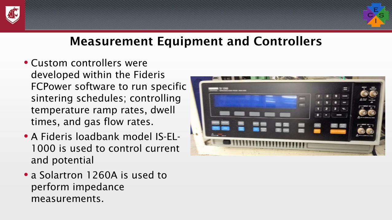
• Custom controllers were developed within the Fideris FCPower software to run specific sintering schedules; controlling temperature ramp rates, dwell times, and gas flow rates.
• A Fideris loadbank model IS-EL-1000 is used to control current and potential
• a Solartron 1260A is used to perform impedance measurements.

Stack Compression• Originally intended to be
accomplished with Inconel bolts, but stress relaxation was severe.
• Instead, a 1.9” diameter Conax pressure fitting was used to allow a stainless-steel ram to be routed through the top lid of the furnace.
• A ball and socket joint provides a fully supported bearing surface
• A 20-ton hydraulic ram supplies the compressive force necessary.

Task 2: Stack Design
• Initial concept for the stack was to use complaint current collectors on both anode and cathode sides to ease tolerancing.
• Additionally, flow plates would be reusable to reduce costs.
• The reusable stack concept has proven difficult to implement, and disposable stack options are being pursued.
Stack Concepts

Reusable Stack Concept• Flow plates are machined from 1/8” 430
stainless
• Coated in a manganese cobaltite spinel to increase electrical conductivity and reduce chromium poisoning of the cathode.
• The stack can be configured to run in crossflow or co-flow
• The membrane is bonded to the tray using glass, sealing the stack internally.
• Thermiculite gaskets seal the stack from the external environment.
• The anode current collector is a nickel mesh (or gauze).
• The cathode current collect is either cobalt nickel foam, or utilizes direct contact with an LSM paste.

Glass Sealing Issues
• Originally bonding the cell to the tray was a separate step, the tray, glass seal, and cell would be fired and then later assembled into the stack.
• Often the glass would not bond to the metal at all, or if it did there would be severe cracking.

Firing Atmosphere
• Cracking and delamination were caused partly by firing the glass in an inert atmosphere.
• The glass contains an organic binder which requires oxygen to burn out, which is intended to take place at around 500 °C.
• Without oxygen, large amounts of carbon would remain in the glass making it mechanically very weak and dark in color

Tray Pre-Oxidation• It was discovered that the 430 stainless steel tray needed
to be pre-oxidized.
• Gives the glass a chemically and COE (Coefficient of Expansion) compatible surface to bond with.
• Helps limit diffusion of network modifiers like 𝐹𝐹𝑒𝑒2+ from the substrate surface.
• This pre-oxidation was initially performed in air at 800 °C but the oxide layer formed was not the pure Cr2O3 desired, and often spalling and iron nodules were visible.
• To solve this issue, the tray was fired in a wet hydrogen environment of about 10/90 H2O/H2 at 950°C.

Examples of Tray FiringTray Fired in Air Tray Fired in Wet Hydrogen

Co-efficient of Expansion Issues
• COE mismatch between the cell and tray was still and issue, cracking occurs upon cooling.
• To work around this, the glass sintering was done in-situ, meaning the cell and tray are bonded within the assembled stack.

Successful Test Run
• Performed an anode supported RIST cell (no longer manufactured).
• Active area of 9 x 9 cm
• Temperature was 750 C
• With cathode air flow at 2.15 slpm and an anode flow of 1.2 slpm of H2 and 100 g/hr of H2O.

Remaining Issues with Reusable Stack Concept• The stack can’t handle thermal cycling or glass/cell
crack.
• Warping of components creates tolerance issues and can result in cracking of the cell.
• Excessively large seal area necessitates very large compressive forces which is hard on stack components.
• Thermal cycling of flow plates has caused coatings to delaminate.
• Testing with the reusable stack concept continues, however, a disposable stack is being pursued to eliminate these issues.

Disposable Stack Concept
• A disposable stack can:– Reduce costs associated with testing SOFC’s.– Increase repeatability and test quality.– Allow for destructive tests such as cross-sectional
SEM imaging
• The stack needs to be made very inexpensively so it must be made from thin, inexpensive sheets of 430 SS.
• Vendors of SOFC coatings are too expensive so an in-house coating system must be developed.

Laminated Object Stack• Inspired by the additive
manufacturing technique called Laminated Object Manufacturing, this stack concept takes individual water-jetted layers and welds them into a gas tight unit.
• Eliminates the need for a glass seal, uses only compressible gaskets.
• Any thickness cell can be used by changing spacer thickness.

Proposed Coating Systems
• Conductive spinel layers are a promising coating system due to:– High conductivity at elevated temperatures– Close CTE match to ferritic stainless steels– Excellent ability to absorb chromium species
• Of binary spinel oxides, Co-Mn has a very high conductivity at 60
𝑆𝑆𝑐𝑐𝑚𝑚2 [1].
• Co-Mn coatings have received wide attention in literature and represent the state of the art in coatings for SOFC.
[1] N. Shaigan, W. Qu, D. G. Ivey, and W. Chen, “A review of recent progress in coatings, surface modifications and alloy developments for solid oxide fuel cell ferritic stainless steel interconnects,” J. Power Sources, vol. 195, no. 6, pp. 1529–1542, Mar. 2010.

Electrodeposition of Mn-Co Coatings• Many techniques exist for depositing Mn-Co coatings, however
electrodeposition followed by thermal annealing is a simple and
inexpensive technique.
• After a wide survey of literature, the work of Wu et al [1] was selected
as a basis, due to the fact that plating parameters used such as
current density, pH, and electrolyte composition have undergone a
rigorous optimization process and coatings were tested in a stack
environment for extended periods of time.
• The coating will be tested on small samples and plating parameters
will be adjusted before attempting on a full size flow plate. [1] J. Wu, Y. Jiang, C. Johnson, and X. Liu, “DC electrodeposition of Mn–Co alloys on stainless steels for SOFC interconnect application,” J. Power Sources, vol. 177, no. 2, pp. 376–385, Mar. 2008.

Future Work
What's Left to do.

Task 3: Preliminary Characterization
• Impedance Spectroscopy is a technique which imposes a sinusoidal AC signal on a test device and sweeps through frequencies.
• Determines the impedance of the device as a function of frequency, and can give some information about the resistances of physical processes.
• One way to interpret impedance spectra is through a Distribution of Relaxation Times analysis.
• Data is taken from a function of frequency to a distribution of time constants.
Impedance Spectroscopy and Distribution of Relaxation Times
[1] E. IVERS-TIFFÉE and A. WEBER, “Evaluation of electrochemical impedance spectra by the distribution of relaxation times,” J. Ceram. Soc. Japan, vol. 125, no. 4, pp. 193–201, 2017.

Data Validation
• DRT analysis requires high quality data.
• Data which passes the Kramers Kronig test meet the criteria of linearity, causality, stability, and finiteness and are valid impedance spectra.
• “KK test for windows” is free software which can be used for this purpose. [1] A. Leonide, SOFC modelling and parameter identification by means of impedance spectroscopy.
Technische Informationsbibliothek u. Universitätsbibliothek, 2010.
Process Identification
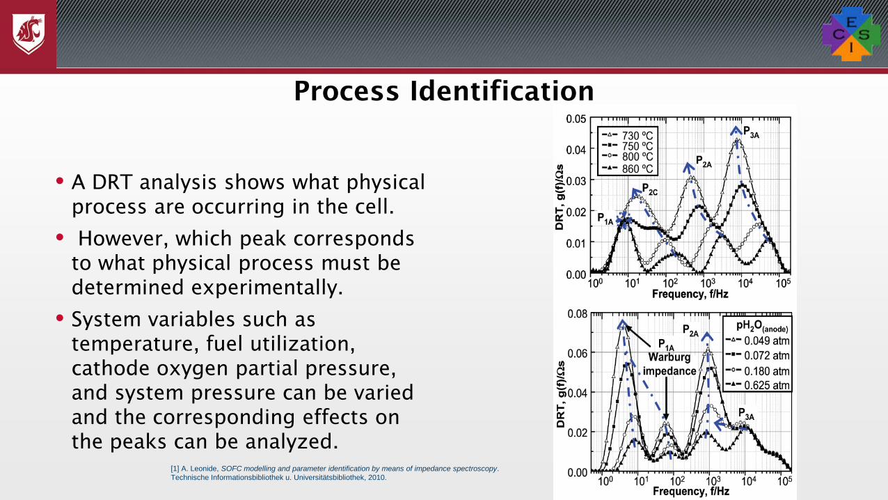
• A DRT analysis shows what physical process are occurring in the cell.
• However, which peak corresponds to what physical process must be determined experimentally.
• System variables such as temperature, fuel utilization, cathode oxygen partial pressure, and system pressure can be varied and the corresponding effects on the peaks can be analyzed.
[1] A. Leonide, SOFC modelling and parameter identification by means of impedance spectroscopy. Technische Informationsbibliothek u. Universitätsbibliothek, 2010.

Task 4: Durability Testing
• After establishing the physical significance of each peak in the DRT spectra, the next step will be conducting long term durability testing.
• Compare the performance of both anode and electrolyte supported cells under standard operating conditions and pressurized operation with pure oxygen.
• Both tests will be performed galvanostatically at a current density of .5 A∙cm-1, a fuel utilization of 70%, an oxygen utilization of 20%, and a constant operating temperature of 750 °C.
• The electrolyte supported cells to be used in this work will be Nextcell-10 cells from Nexceris, and Elcogen cells will be used for anode supported cells.
Test Plan
Parameters Kerafol 1
Kerafol 2
Kerafol 3
Nextcell-10
Elcogen
Electrolyte type, Thickness 8YSZ, 150 µm
YScSZ, 150 µm
10Sc1CeSZ,
150 µm
Hionic .13-.17
mm
YSZ 3-6 µm
Anode Type, Thickness NiO/
GDC, 40 µm
NiO/ GDC, 40 µm
NiO/ GDC, 40 µm
NiO-GDC
50 µm
NiO/YSZ
.530 mm
Cathode Type, Thickness LSCF, 40-50 µm
LSCF, 40-50 µm
LSCF, 40-50 µm
LSM/ LSM-GDC 50 µm
LSC 12 µm
Operating Temperature (°C)
850 850 850 750-850 600-750

Degradation Rate
• Degradation rate in % per hour voltage drop relative to initial voltage can be calculate using the formula:
• Where U is potential, 𝑗𝑗𝑐𝑐 is a constant current density, 𝑡𝑡 is time, and 𝑡𝑡0 is the initial time.
• Additionally, the ohmic, polarization, electrochemical, and gas concentration resistance can easily be read from a Nyquist plot of the impedance data [38] R. Rode, P. Vang, R. Gottrup, and D. Version, Solid Oxide Fuel Cell Stack Diagnostics Rasmus
Rode Mosbæk Department of Energy Conversion and Storage Ph . D . Thesis , October 2014. 2014.
𝐷𝐷𝐷𝐷 𝑡𝑡 = 100 �𝑈𝑈 𝑗𝑗𝑐𝑐 , 𝑡𝑡0 − 𝑈𝑈 𝑗𝑗𝑐𝑐 , 𝑡𝑡𝑈𝑈 𝑗𝑗𝑐𝑐 , 𝑡𝑡0 � 𝑡𝑡 − 𝑡𝑡0

Task 5: Post Mortem Analysis
• Scanning Electron Microscopy (SEM) and Energy Dispersive Spectroscopy (EDS) will be used in this work to analyze the various components of the SOFC to determine degradation mechanism.
• Potential degradation mechanisms include:
• Fractures in the electrolyte due to large chemical and thermal stresses [39],
• Failure of cathode coatings and subsequent oxidation and resistance increases [15],
• Chrome poisoning of the cathode[40],
• Nickel coarsening in the anode [41]
• Likely the Mn-Co coating will be a significant source of that degradation and can easily be characterized through SEM and EDS.
Characterization Techniques
[1] A. Atkinson, “SOLID STATE ioN#a Chemically-induced stresses in gadolinium-doped ceria solid oxide fuel cell electrolytes,” 1997.[2] J. C. W. Mah, A. Muchtar, M. R. Somalu, and M. J. Ghazali, “Metallic interconnects for solid oxide fuel cell: A review on protective coating and deposition techniques,” Int. J. Hydrogen Energy, vol. 42, no. 14, pp. 9219–9229, Apr. 2017.[3] M. Kornely, A. Neumann, N. H. Menzler, A. Leonide, A. Weber, and E. Ivers-Tiffée, “Degradation of anode supported cell (ASC) performance by Cr-poisoning,” J. Power Sources, vol. 196, pp. 7203–7208, 2010.[4] S. Koch et al., “Solid Oxide Fuel Cell Performance under Severe Operating Conditions,” Fuel Cells, vol. 6, no. 2, pp. 130–136, 2006[5] Z. Yang et al., “Investigation of iron–chromium–niobium–titanium ferritic stainless steel for solid oxide fuel cell interconnect applications,” J. Power Sources, vol. 183, no. 2, pp. 660–667, Sep. 2008.

Timeline
Task Start Completion Status Task 1 Fall 2015 Spring 2017 Completed Task 2 Fall 2015 Fall 2018 In progress Task 3 Spring 2019 Summer 2019 In progress Task 4 Summer 2019 Fall 2019 Waiting Task 5 Fall 2019 Winter 2019 Waiting PhD Defense Spring 2020