degradation of monolithic refractory linings during drying...
TRANSCRIPT

Schmitt et al. Damage of monolithic refractory linings in steel ladles during drying
Damage of monolithic refractory linings in steel ladlesduring drying
N. Schmitt(1)&, Y. Berthaud(1), J.F. Hernandez(1), P. Meunier(2), J. Poirier(3)
(1)LMT-Cachan (ENS de Cachan/CNRS-UMR 8535/University Paris 6) 61 avenue du Président Wilson, F-94 235 Cachan (France)
(2) Lafarge Refractories 4 allée de Lausanne, F-38 078 Saint Quentin Fallavier (France)
(3) Arcelor-Sollac, Grande Synthe, F-59 381 Dunkerque (France), now atCRMHT – CNRS, 1D av. de la Recherche Scientifique F-45 071 Orléans (France)
&Corresponding author : Email: [email protected]
Abstract:
Safety linings of steel ladles are made of high content alumina castable. In situ observations confirm that during drying, a network of macrocracks appears in the monolithic castable lining, owing to both dehydration of the cement paste and temperature. The dehydration kinetics is characterised during the life of the lining. To simulate the behaviour of the lining, the thermo-mechanical behaviour of the castable was characterised by compression and three point bend tests, thermal dilatation tests and TGA analysis in the 20-600°C temperature range. It is shown the change in properties is shown to be due mainly to transformation of hydrates in the castable. Numerical simulations of the lining drying process were also performed using a finite element code to verify the causes of cracking. A parametric study was carried out to examine the possibility of reducing the stresses induced by thermal loading. Improved thermal insulation and better control of the heating a reduce the risk of failure in the lining.
Keywords: castable, drying, thermomechanical behaviour, refractory lining, damage, finite element method
PREPRINT
Published in British Ceramic Transactions (2004 )
- 1 -

Schmitt et al. Damage of monolithic refractory linings in steel ladles during drying
Introduction
Over the last ten years, there has been a noticeable evolution in the refractory lining technology used in the steel industry. Both the chemical composition of refractories and the design of the lining have been improved, so that lining lifespan is now significantly extended. In steel ladles, a multilayer lining is commonly used. This is made up of a metallic shell on the outside of the vessel, an insulating shell to reduce heat transfer, a safety lining and a working lining which is in contact with the molten metal and slag.
Many studies have been carried out on the causes of the degradation of refractories in contact with slag during steelmaking since the working lining needs changing quite often. Moreover there is a demand for more accurate control of the chemical composition of the steel which requires the pollution level in the metal bath resulting from dissolution of the refractory to be limited.1 Corrosion due to impregnation of refractories by slag is the major cause of wear that induces progressive reduction of the thickness of the working lining. Consequently, studies have so far focused mainly on physico-chemical aspects,2-5 notably on phase transformations occurring at high temperature and dissolution of some phases that lead, for example, to the decohesion of oxide grains in refractory materials. Some studies have also examined the role of stress induced by thermal expansion or slag interstitial pressure in impregnated refractories on damage or spalling of the lining (e.g., Blond et al.6). New solutions have been proposed to improve the resistance to wear and corrosion of the working lining. Significant improvements in service life are observed with monolithic refractories such as alumina-spinel or alumina-magnesia (spinel forming) castables.7 The development of alumina-magnesia-carbon formulations for the wall linings of steel ladles is also promising.4
Few studies deal with the resistance of the safety lining when the masonry lining is replaced by a alumina cement castable monolithic lining, which has the advantage of being easier to manufacture. While the working lining has to be changed every 30-40 cycles, the safety lining is replaced about 15 times less frequently. Degradation that can occur during drying of the castable owing to excessive vapour pressure developed in the cement paste has been eliminated thanks to an increase in permeability and the use of ultralow cement castable. However, the main function of the safety lining, which is to prevent the hot liquid metal that goes through the working lining from reaching the outer steel shell, is not always secured as many cracks exist. Consequently, poor lining reliability threatens both steel production and the safety of staff and facilities.
The aim of the present work was to analyse the causes of cracking in the safety lining and to examine whether technical improvements are possible to delay the inception of cracks during the drying phase. The progressive degradation observed in safety linings of several ladles from the Arcelor-Sollac's Dunkerque plant is shown. In particular, data on crack location, density and opening of crack change were collected and summarized. The thermomechanical behaviour of castables used in the safety lining is characterised. Results of compression tests, three point bend tests, thermal expansion tests and TGA analyses are presented and simplified constitutive equations are proposed to account for the dehydration process that occurs during drying. Finally, the results of finite element simulations of drying of the safety lining performed with an industrial code are presented. The drying operation currently used in steel plants is first simulated to determine the stress state in the lining. The influence of three parameters (thermal resistance of the insulated shell, maximum drying temperature and cooling rate) on the stress level is then examined. These parameters seem to be the easiest to modify in steel plants.
In situ degradation of safety linings
Steel ladle structure The typical structure of a multi-layered ladle lining is shown in Fig. 1. The ladle is a large vessel, 4.25 m in
diameter and 4.245 m high, in which the steel is refined. The lining consists of an outer steel shell (about 38 mm thick), an isolating shell (about 10 mm thick) to reduce the heat transfer, a monolithic safety lining (about 100 mm thick) and a working lining (about 150 mm thick) which is a masonry structure made up of bauxite and magnesia-carbon bricks. The steel shell is reinforced near the swivel pins at 90° and 270° for lifting and moving of the vessel after refining and for pivoting it during the replacement of the lining.
- 2 -

Schmitt et al. Damage of monolithic refractory linings in steel ladles during drying
Figure 1: Refractory lining of a ladle
Safety lining refractoriesIn the 1980s, to increase the performances of refractories, ultra low cement castables (ULCC) were
developed, notably by Lafarge8. The ULCC used in SOLLAC Dunkerque ladles is made of bauxite aggregates with size in the range 0.1- 5 mm, fine calcined alumina particles (1-10 µm) and silica fume particles (≈ 0.3 µm) to reduce the porosity and increase the strength at medium and high temperatures.
The cement SECAR 71 (2 wt-%) made by Lafarge Aluminate is essentially composed of monocalcium Aluminate CaOAl2O3 (61 wt-%) and bicalcium aluminate CaO.2Al2O3 (37.5 wt-%). During the hydration process, water reacts with the cement to form hydrates whose chemical composition depends on the setting and hardening temperature. 9,10
In the absence of silica fume, the metastable hydrates transform slowly into stable hydrates AH3 and C3AH6,11
where Bogue's notation is used (A = Al2O3,C = CAO, H = H2O). These hydrates are present after curing at 120°C. This reference state is widely accepted in the refractory industry. During drying, the hydrates turn progressively into new anhydrates. The chemical decomposition process is complex but as a first approximation the decomposition of each stable hydrate can be described by two stoechiometric reactions,11-13 so that it is possible to model the kinetics of the dehydration process.14
When silica fume is added, it is more difficult to identify the phases formed during hydration and dehydration because four basic compounds are present. Some studies (e.g. Monsen et al.15) give information but to the present authors' knowledge, a fine description of these reactions has not been proposed.
Thermal history of safety lining
To better understand the complex thermal loading of the safety lining, the main stages are mentioned. When a new lining is built, first the monolithic safety lining is cast, just after the shotcreting of the insulating refractory. Bauxite-based concrete with ultralow alumina cement content is currently used for this lining. The filling of the mould is made continuous so that no joint are formed during casting. After setting and hardening for about a day at room temperature, the vessel is moved under a gas burner and heated up to 650°C to eliminate free and chemical bounded water. First the inner temperature is raised at a rate of about 35°C.h -1 up to 125°C and is maintained for 4 h to eliminate free water. It is then raised at a rate of 55°C.h -1 up to 650°C and maintained for 7 h 30 before the burner is stopped and the vessel is cooled down to room temperature. The cooling stage lasts about a day. In practice, measurements have found temperature differences up to 80°C between the top and the bottom of the wall,16 because it is very difficult to reach a uniform temperature rise with a gas burner. When the wall is cold, the working masonry lining is built and the ladle is moved to the area where the lining is preheated. The inner temperature is increased up to 1200°C at a rate of 90°C.h-1. The temperature of the inner surface of the safety lining reaches about 800-900°C. After, this stage, the steelmaking thermal cycling takes place. The
- 3 -

Schmitt et al. Damage of monolithic refractory linings in steel ladles during drying
temperature of the safety lining varies between about 1000°C at the end of the refining process of steel to 600-700°C just before the vessel is filled with a new batch of molten metal. After 30-40 cycles, the working lining is demolished and the safety lining cooled down to room temperature before a new masonry is built.
Safety lining degradations
In situ observations of safety linings were carried out in the steelmaking shop at Arcelor Sollac Dunkerque to diagnose the mechanisms responsible for damage. Inspections were made after casting of the lining and drying of the castable and during replacement of the working linings until the demolition of the safety lining. For practical reasons and to ensure repeatable results, several ladles linings were observed. The main results are summarised below.
It is well known that shrinkage occurs in concrete during the setting and hardening stages.17 However the strain remains low because the ULCC contains only a small content of alumina cement. Thus, the stresses developed at this stage in the lining remain low and no crack are detected by visual observations on the inner surface of the lining. Yet, the existence of cracks at this stage cannot be ruled out.
Mainly horizontal cracks were observed on the inner face of the lining after cooling following the thermal treatment corresponding to the drying schedule of the linings. The distance between these cracks was 700-900 mm and the crack opening was about 1-2 mm. Vertical cracks were also observed but their opening size was lower. They were uniformly distributed around the lining. At this step, the monolithic character of the lining is lost: an assembly of slabs forms the layer. These cracks were due to i) the heterogeneous thermal expansion generated by the heat treatment and ii) the irreversible change in the thermo-mechanical properties resulting from dehydration of the castable paste.
After one cycle, these cracks became more visible as shown in Fig. 2. They formed a nearly square network 800-900 mm in width that was uniform around the lining. At this stage, the horizontal crack opening displacement reached 3 to 4 mm while the vertical crack opening displacement reached 2 to 3 mm. A secondary crack network occurred due the cracking of the slabs but their opening displacement remained low (0.1 to 0.5 mm). Cracking probably started during the drying stage but was not detected because the opening size was so low.
Figure 2: Cracks observed after 1 cycle on inner surface of ladle lining; rule at left = 900mm
Degradation of the lining continued during the first 16 cycles, but it became asymmetric (Figs. 3 and 4). The principal cracks opening reached 30mm on the side where the ladle was swung (angular position 0°) and 50mm on the opposite side (angular position 180°). The secondary crack opening displacement increased too, in particular after the 7th cycle. The crack network became denser on the "180° side" where the crack spacing was about 300 mm in width after 11 cycles, than at the "0° side" where the spacing was about 450 mm. This density of cracks kept increasing to reach the final state of the lining as shown in Fig. 5.
- 4 -

Schmitt et al. Damage of monolithic refractory linings in steel ladles during drying
0
10
20
30
40
50
0 2 4 6 8 10 12 14 16
0° side
180° sideC
rack
ope
ning
dis
plac
emen
t (m
m)
Number of cycles
0
10
20
30
40
50
0 2 4 6 8 10 12 14 16
Secondary cracks
Principal cracks
Cra
ck o
peni
ng d
ispl
acem
ent (
mm
)
Number of cycles
"180° side"
Figure 3: Horizontal principal crack openingdisplacement on inner surface of lining
Figure 4: Horizontal principal crack and secondary crack opening displacement on "180° side" of lining
"0° side" "180° side"
Figure 5: Cracks observed on inner surface of the lining after 16 cycles
In practice, the crack opening displacement was only measured on the inner side of the wall and reached an maximum value. The opening decreases rapidly with depth because refractory is torn away from the lips of crack . This loss of mass probably occurs during the replacement of the working lining as a results of the vibrations generated by a pick hammer in the safety lining during demolition of the working lining. To ensure metal tightness the holes are filled up at each cycle using a ceramic mortar.
These observations demonstrate that the castable does not ensure the monolithic function of the safety lining. Regular repair of the lining cannot be avoided. Improving reliability means delaying the crack inception, in particular during the drying stage.
Thermo-mechanical behaviour of the castable
The thermomechanical behaviour of ULCC has been studied in detail in the temperature range 20-600°C corresponding to the drying phase. The main experimental results are presented.
Experimental investigation
Mechanical testsCompression tests are carried out on cylindrical samples (25 mm in diameter and 80 mm tall) and three-point
bend tests on prismatic samples (25 mm×25 mm×150 mm). To limit the effect of heterogeneity, the maximum size of aggregates was limited to 3.15 mm instead of 5 mm. Consequently, the composition of the castable is slightly modified to obtain the same behaviour. All samples were dried at 110 °C for two days before testing. For the tests performed at high temperature, a heating rate of 200°C.h-1 was applied and the samples were soaked for 5 h at the test temperature. Monotonic mechanical load was then applied using a servo-hydraulic testing machine under displacement control (namely, 1.67 10-5 s-1 strain rate for the compression tests, 5.0 10-2 mm.s-1 deflection rate for three point bend tests).
- 5 -

Schmitt et al. Damage of monolithic refractory linings in steel ladles during drying
While bauxite aggregates provide castables with most of their refractory properties, cement paste binds the oxide grains. In compression, the refractory exhibits quasi-brittle behaviour (Fig. 6). Loading-unloading in compression tests highlights the non-linear behaviour, i.e., decrease in stiffness, appearance of permanent strains, softening due to the degradation of bonds between the grains and binder and microcracking in the binder observed by SEM analysis of fractured surfaces. This behaviour is similar to that observed in standard concretes.18
-50
-40
-30
-20
-10
0
-0.3 -0.2 -0.1 0
Stre
ss (M
Pa)
Strain (%)
Figure 6: Stress-strain curve for ULCC under compression test at room temperature
Compression tests performed at different temperatures in the range 20 – 600°C show that the same physical mechanisms are responsible for the non-linear behaviour. For this material, testing showed that compression strength σrc, maximal strain in compression and modulus of rupture MOR under bend test increase with temperature, as shown in Figs. 7 and 8. Young's modulus E, determined in compression tests decreases with the temperature. Strength evolves contrary to the one observed for high alumina cement castable.19
-80
-60
-40
-20
0
-1 -0.8 -0.6 -0.4 -0.2 0
Stre
ss (M
Pa)
Strain (%)
20 °C
210 °C350 °C
600 °C
0
20
40
60
80
0
10
20
30
40
0 100 200 300 400 500 600
Stre
ngth
(MPa
)
Young's M
odulus (GPa)
Temperature (°C)
E− σ rc
M.O.R.
Fig. 7: Stress-strain curves for ULCC in compression tests for different temperatures
Fig. 8: Change in mechanical properties with temperature for ULCC
At high temperatures, typically above 800°C, other physical mechanisms (e.g. sintering20) occur that are responsible for a rapid decrease in mechanical properties (stiffness and strength). In particular, silica oxides react with alumina oxides to form new mineralogical phases. This phenomenon explains the visco-plastic behaviour and the strong increase in maximum strain observed in compression tests.19
In the temperature range 20 to 600 °C, it is also observed that specimens tested at room temperature after a heat treatment at a given temperature have similar behaviour to specimens tested at high temperature. This observation demonstrates that the mechanical properties are mainly dependent on the state of phase transformation (i.e., state of dehydration of the cement paste) and vary little with temperature.
- 6 -
Schmitt et al. Damage of monolithic refractory linings in steel ladles during drying
Physicochemical tests
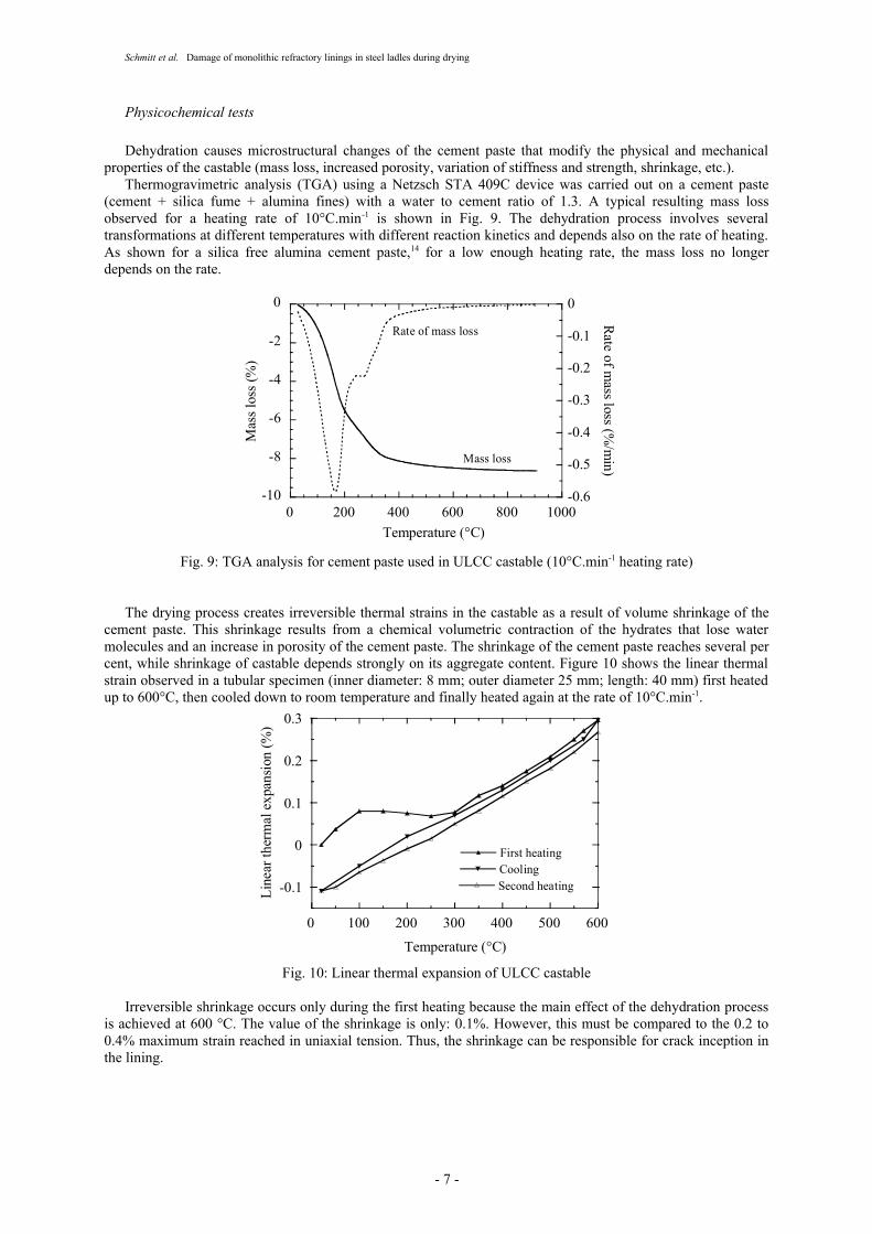
Dehydration causes microstructural changes of the cement paste that modify the physical and mechanical properties of the castable (mass loss, increased porosity, variation of stiffness and strength, shrinkage, etc.).
Thermogravimetric analysis (TGA) using a Netzsch STA 409C device was carried out on a cement paste (cement + silica fume + alumina fines) with a water to cement ratio of 1.3. A typical resulting mass loss observed for a heating rate of 10°C.min-1 is shown in Fig. 9. The dehydration process involves several transformations at different temperatures with different reaction kinetics and depends also on the rate of heating. As shown for a silica free alumina cement paste,14 for a low enough heating rate, the mass loss no longer depends on the rate.
-10
-8
-6
-4
-2
0
-0.6
-0.5
-0.4
-0.3
-0.2
-0.1
0
0 200 400 600 800 1000
Mas
s los
s (%
)Rate of m
ass loss (%/m
in)
Temperature (°C)
Mass loss
Rate of mass loss
Fig. 9: TGA analysis for cement paste used in ULCC castable (10°C.min-1 heating rate)
The drying process creates irreversible thermal strains in the castable as a result of volume shrinkage of the cement paste. This shrinkage results from a chemical volumetric contraction of the hydrates that lose water molecules and an increase in porosity of the cement paste. The shrinkage of the cement paste reaches several per cent, while shrinkage of castable depends strongly on its aggregate content. Figure 10 shows the linear thermal strain observed in a tubular specimen (inner diameter: 8 mm; outer diameter 25 mm; length: 40 mm) first heated up to 600°C, then cooled down to room temperature and finally heated again at the rate of 10°C.min-1.
-0.1
0
0.1
0.2
0.3
0 100 200 300 400 500 600
First heatingCoolingSecond heatingLi
near
ther
mal
exp
ansi
on (%
)
Temperature (°C)
Fig. 10: Linear thermal expansion of ULCC castable
Irreversible shrinkage occurs only during the first heating because the main effect of the dehydration process is achieved at 600 °C. The value of the shrinkage is only: 0.1%. However, this must be compared to the 0.2 to 0.4% maximum strain reached in uniaxial tension. Thus, the shrinkage can be responsible for crack inception in the lining.
- 7 -

Schmitt et al. Damage of monolithic refractory linings in steel ladles during drying
Constitutive equations
The non-linear mechanical behaviour of the castable in the temperature range 20°C-600°C, due to debonding of the interface between the grains and the cement paste matrix and to microcracking can be described by damage variables.21 In this model, an internal scalar variable D characterises the state of degradation of the material. For quasi-brittle material, many more or less complex models have been proposed to take into account stiffness reduction, isotropic or anisotropic description and permanent strains (see Allix and Hild22 for a recent review). For alumina castables, Hernandez et al.23 identified an elastic-viscoplastic isotropic damage model developed for magnesia-carbon refractories.24 Yet, such models present a softening behaviour that induces well-known numerical problems in structural computations, such as strain localisation or mesh sensitive energy dissipated by damage.25,26 Solutions exist to overcome these problems by using non-local models, for example by introducing an internal length scale.27,28 However these models remain difficult to use, particularly to study structures with high gradient body force loadings. Several authors29,30 have proposed other non-linear constitutive equations based on elastoplastic behaviour.
Nevertheless, to predict the stage at which damage occurs in the lining during drying, a linear thermo-elastic approach accounting for phase transformations is sufficient as a first attempt. To take into account the non-linear behaviour induced by dehydration of the castable, additional state variables ζ must be introduced, characterising the degree of conversion of hydrates into dehydrated phases. A suitable description of the state of dehydration is achieved by defining as many variables and kinetic laws as observed reactions.14 But for a cement paste containing silica fume, the number of variables cannot be defined as the dehydration reactions are very complex and have not all been identified. Besides, as vapour pressure does not build up during heating because vapour easily flows through the refractory lining, it is not necessary to calculate precisely the vapour pressure generated by the loss of chemical bounded water that may cause explosion by overpressure. Thus, a complex model, such that proposed for concrete to study fire resistance (e.g., Gawin et al.31) in the framework of mechanics of porous continuum32 is not useful.
Lastly, the heating rate is low. Consequently, the dehydration kinetics, i.e. the mass loss, is less dependent on time for heating rates less than 1°C.min-1. For these reasons, only one internal scalar variable ζ is introduced to describe the dehydration process. On the face of it, this variable must be the ratio of loss of water mass. As the state of dehydration depends only on the maximum temperature reached, the internal variable ζ is defined as follows. Its value varies from zero to one with the maximum temperature Tmax reached during the heating phase in the temperature range [T1, T2], where T1 is the temperature above of which the conversion of hydrates begin and T2 the temperature above which the dehydration stops. The kinetics of the degree of advancement of the phase transformations are given by
ζ = 0 if Tmax ≤ T1
if T1 ≤ Tmax ≤ T2 (1)
ζ = 1 otherwisewhere a is a material parameter.
The law of thermoelasticity reads
σ = E(T,ζ).(ε - εth - εsh) (2)
where σ is the Cauchy stress tensor, ε the total strain tensor, εth the thermal expansion tensor equal to α(T,ζ).(T-To).I with I the second rank unit tensor and To is the initial temperature. The secant coefficient of thermal linear expansion α(T,ζ) is both dependent on the temperature and the state of dehydration. εsh models shrinkage and depends only on the state of dehydration. α(T,ζ) is given by a law of mixture
α(T,ζ) = α(T,ζ=0) (1 - ζ) + α(T,ζ=1) ζ (3)
and εsh is defined as
εsh = εosh.g(ζ).I (4)
where εosh the maximum shrinkage and g(ζ) a function increasing with ζ.
The failure of the castable is described by a criterion of the form where is a failure function that accounts for the asymmetric strength behaviour in tension and compression. In numerical computations, the material breaks when the stress exceeds the ultimate strength, i.e., . The failure function Yf proposed by Schmitt et al.24 is used
- 8 -
Schmitt et al. Damage of monolithic refractory linings in steel ladles during drying
(5)
where I1 = Tr(σ) is the first invariant of the stress tensor, J2 = 1/2.(S:S), S is the deviatoric stress tensor, K(T,ζ) and G(T,ζ) the compressibility modulus and shear modulus, B(T,ζ) and R(T,ζ) are two material parameters dependent on compression strength σrc(T,ζ) and tensile strength σrt(T,ζ) and are given by
and (6)
The temperatures T1 and T2 and the parameter a were identified by TGA analysis of a cement paste previously dried at 120 °C. The other parameters were identified by compression and bend testing. Considering as a first approximation that the properties do not depend on temperature, the dependence of properties on ζ is easily identified.
Numerical simulations
Finite element modelling
Computations of the stresses occurring during the drying process were performed using the Abaqus finite element code.33 The constitutive equations of the thermomechanical behaviour of the castable were implemented in a user material routine.
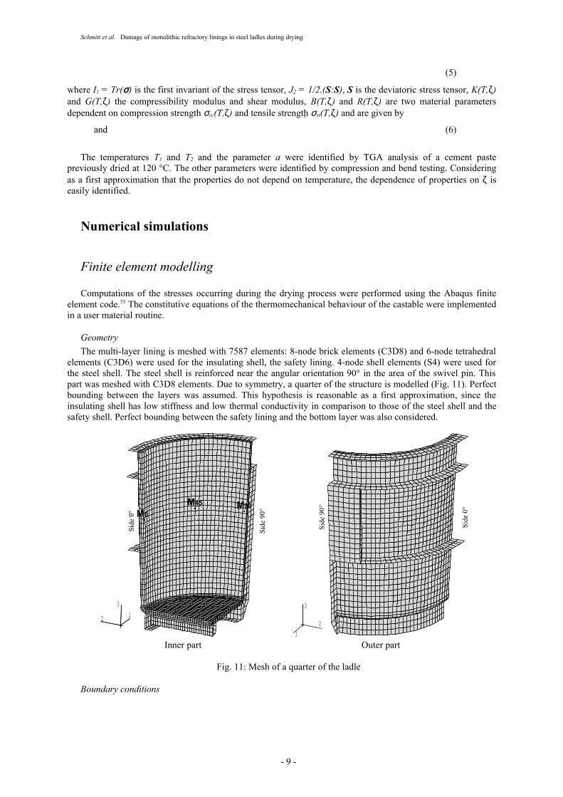
GeometryThe multi-layer lining is meshed with 7587 elements: 8-node brick elements (C3D8) and 6-node tetrahedral
elements (C3D6) were used for the insulating shell, the safety lining. 4-node shell elements (S4) were used for the steel shell. The steel shell is reinforced near the angular orientation 90° in the area of the swivel pin. This part was meshed with C3D8 elements. Due to symmetry, a quarter of the structure is modelled (Fig. 11). Perfect bounding between the layers was assumed. This hypothesis is reasonable as a first approximation, since the insulating shell has low stiffness and low thermal conductivity in comparison to those of the steel shell and the safety shell. Perfect bounding between the safety lining and the bottom layer was also considered.
12
3
M45 M90M0
2
3
1
Inner part Outer part
Fig. 11: Mesh of a quarter of the ladle
Boundary conditions
- 9 -

Schmitt et al. Damage of monolithic refractory linings in steel ladles during drying
Heat transfer between the burner and the safety lining is very complex to model. For the sake of simplicity, it was assumed homogeneous on the overall internal surface of the lining (vertical and horizontal parts) and was simulated by thermal convection flux φ = hin (T – Tin). The inner temperature was given by the heating schedule and the thermal convection coefficient was fitted so that the numerical simulations of temperature fields corresponded to in situ measurements. The heat transfer between the steel shell and the environment was also modelled by convection flux (hex, Tex).
The values of these parameters are listed in Table 1. Linear change with time of heat convection coefficient hin was considered when it varied in a single heating stage. At t = 0, all parts are at room temperature (To = 20°C).
Table 1: Heat convection coefficient hin and temperature Tin used in F.E. model of inner side of safety lining; for outer side hex = 5 Wm-2K-1 and Tex = 20 °C
Time 0 h - 3h 3 h - 7h 7 h - 16 h 30 16 h 30-24 h 24 h - 36 hInner side of the safety lining
hin (Wm-2K-1) 5-30 30 30-60 60 20-5Tin (°C) 20-125 125 125-650 650 20
As far as mechanical boundary conditions are concerned, the vessel is subjected to gravity loading. With the vessel lying on the ground, it is assumed that the vertical displacement of nodes in contact with the ground was fixed. The inner surface of the safety lining and the external surface of the steel shell are free of stress.
Constitutive laws for steel and insulating refractory
As the thermal properties of refractories and steel are less dependent on the temperature, they are assumed either constant or to vary linearly in the temperature range 20°C-700°C (Table 2).
Table 2: Thermal properties of materials
Properties ULCC Insulating refractory SteelThermal conductivity 20°Ccoefficient (W. m-1.K-1) 700°C
2.21.6
0.150.18
5454
Heat capacity (J.kg-1.K-1) 1000 1380 460Density (kg.m-3) 2600 600 7800
Thermoelastic behaviour is assumed for both the insulating refractory and the steel (Table 3). Note that Young's modulus of the refractory is arbitrarily low because it is assumed that the stiffness of the insulating shell is very low during the drying stage. Not only does the insulating refractory have high porosity, but in addition the interfaces between the steel shell / insulating layer and the insulating layer / safety lining are weak.
Table 3: Mechanical properties of insulating refractory and steel
Properties Insulating refractory SteelYoung's modulus (GPa) 20°C 450°C
5.0 10-3
5.0 10-3196160
Poisson's ratio 0.2 0.3Thermal expansion 20°C coefficient (K-1) 450°C
1.0 10-5
1.0 10-51.1 10-5
1.3 10-5
The parameters of the constitutive equations for the castable are defined in Table 4.
- 10 -

Schmitt et al. Damage of monolithic refractory linings in steel ladles during drying
Table 4: Parameters of the constitutive equations of mechanical behaviour
Parameters ValuesTemperature limits (°C) T1 = 120 , T2 = 600Kinetic of dehydrationThermal expansioncoefficients (K-1)
α(T,ζ=0) = 10.3 10-6
α(T,ζ=1) = 7.1 10-6
Shrinkage εosh = 0.128%
g(ζ) = min(1.25 ζ, 1.0)Elastic propertiesYoung's modulus (GPa)Poisson ratio
E(T,ζ) =39.2 - 4.67 ζ for ζ ≤ 0.878E(T,ζ) =114.3 - 90.16 ζ for ζ > 0.878ν(T,ζ) = 0.2
Compression strength (MPa) σrc(T,ζ) = -46.3 - 20.16 ζ for ζ ≤ 0.878σrc(T,ζ) = -7.9 - 63.93 ζ for ζ > 0.878
MOR (MPa) σrt(T,ζ) = 4.9 + 3.36 ζ for ζ ≤ 0.878σrt(T,ζ) = -5.08 +14.75 ζ for ζ > 0.878
Results for the standard case
Results are now presented for the standard case. Changes of temperature and stress with time are given for point M0 M45 and M90 located at 2 m from the bottom of the ladle and respectively at angular position 0°, 45° and 90° (Fig. 11), in the area where in situ observations were performed. Maps of axial stress σzz and hoop stress σθθ
are shown at the end of the heating stage and after 2 h of cooling in the drying schedule. In the following discussions, the inner surface is the surface in contact with the working lining and the outer surface is the surface in contact with the insulating layer.
A typical temperature history obtained in the multi-layer lining at point M45 is shown in Fig. 12a. It can be seen that the temperature reaches about 250°C in the shell at the end of heating. The difference in temperature between the inner surface and the outer surface of the safety lining ∆Tc-c increases to 212°C after 16 h 30 and then decreases slowly to 141°C after 24 h. During cool-down, the temperature of the previous hot surface decreases rapidly during the first hour. ∆Tc-c decreases rapidly too and an inversion in sign is observed; in other words the lining undergoes a second thermal shock. The inner surface becomes cooler than the outer surface and ∆Tc-c = -102 °C after nearly 50 min of cooling before it vanishes. This value depends strongly on the heat transfer coefficient hin. When hin is three time higher (hin = 60 W.m-2.°C-1), ∆Tc-c reaches -200 °C.
0
200
400
600
0 6 12 18 24 30 36
Tem
pera
ture
(°C)
Time (h)
Ti-c
Tc-cTc-b
Tc-c∆Point M45
-200
0
200
400
600
0 6 12 18 24 30 36
Tem
pera
ture
(°C
)
Time (h)
Ti-c(M90)Ti-c (M0)
Tc-c(M0)∆
Tc-c(M90)∆
a) Point M45 b) Points M0 and M90
Fig. 12: Temperature histories in lining for standard case; s: steel shell, i-c: interface insulating layer/safety lining, c-c: middle of safety lining, c-b: inner surface of the safety lining
The temperature field is heterogeneous in the safety lining because the steel shell is thicker near the swivel pin. On the inner side of the safety lining, the difference in temperature ∆Ti-c reaches about 100°C at the end of heating (Fig. 12b). The high thermal diffusivity of steel combined with the higher mass of shell near the swivel spin causes a higher heat transfer near this zone.
- 11 -

Schmitt et al. Damage of monolithic refractory linings in steel ladles during drying
The change of hoop stress and axial stress at two typical points is shown in Figs. 13 and 14. The failure function Yf defined by Eq. 5 is also reported. At each point in the drying schedule, the curves of the hoop stress and the axial stress are similar. The hoop stress is significantly higher than the axial stress. Both curves are also similar to those of the failure function that defines a critical state for values of Yf greater than zero. Consequently, Yf is a good indicator for the global analysis of the resistance of the layer and is used later for other analyses.
During the first stage (0-3 h), where no shrinkage occurs, the inner side is subjected to compressive stresses (Figs. 13a and 14a) and the outer side is in tension (Figs. 13b and 14b). During the dehydration of concrete, the stresses history is complex with several inversions of the curve slope. This phenomenon is not observed when shrinkage is not taken into account. During the second plateau of inner temperature at 650 °C, the difference in temperature ∆Tc-c decreases and the stresses move in the tensile direction, due to a structural effect. The cooling of the safety lining induces high tensile stresses on both sides of the lining, due to the "parabolic" form of the temperature profile inside the lining induced by the cooling on both sides. This stage is the critical phase where the highest tensile stresses occur. Shrinkage is responsible for a significant increase in stress levels (at M90, σθθ
max
=31 MPa with shrinkage and 17.4 MPa without). As ∆Tc-c decreases, the stresses decrease too.
-20
-10
0
10
20
30
40
-0.04
-0.02
0
0.02
0.04
0.06
0.08
0 6 12 18 24 30 36
σσYf
Stre
ss (M
Pa)
Failure function (J/m3)
Time (h)
M (IS)0
θ θ
zz
-20
-10
0
10
20
30
40
-0.04
-0.02
0
0.02
0.04
0.06
0.08
0 6 12 18 24 30 36
σσYf
Stre
ss (M
Pa)
Failure function (J/m3)
Time (h)
M (0S)0
θ θ
zz
a) inner surface b) outer surface
Figure 13: Variation of hoop stress σθθ, axial stress σzz and failure function Yf with time at point M0 in the standard case
-20
-10
0
10
20
30
40
-0.04
-0.02
0
0.02
0.04
0.06
0 6 12 18 24 30 36
σσ
Yf
Stre
ss (M
Pa)
Failure function (J/m3)
Time (h)
M (IS)90
θ θ
zz
-20
-10
0
10
20
30
40
-0.04
-0.02
0
0.02
0.04
0.06
0 6 12 18 24 30 36
σσ
Yf
Stre
ss (M
Pa)
Failure function (J/m3)
Time (h)
M (OS)90
θ θ
zz
a) inner surface b) outer surface
Figure 14: Variation of hoop stress σθθ, axial stress σzz and failure function Yf with time at points M90 in the standard case
Maps of hoop stress σθθ and the axial stress σzz are shown in Figs. 15 and 16 at the two critical times. Both stress fields are very heterogeneous in space. The stress maps of confirm that the outer surface is the most stressed at the end of the heating phase and the inner surface during the cooling phase. Moreover the average tensile stress in the area near the angle 0° is higher in the area near the angle 90°. This is a result of the presence of reinforcement parts near the swivel spins that increase the local stiffness of the shell in the 90° area and modify the heat transfer conditions on the outer surface.
- 12 -

Schmitt et al. Damage of monolithic refractory linings in steel ladles during drying
Figure 15: Stress fields at the end of heating (t = 24 h) for the standard case
σ θ θ
1 2
3
12
3
Inner side Outer side
1 2
3
12
3
σ zz
-INF.+5.0+9.0+13.0+17.0+21.0+25.0+29.0+33.0+37.0+41.0+45.0+INF.
-INF.-5.0-2.5-0.0+2.5+5.0+7.5+10.0+12.5+15.0+17.5+20.0+INF.
Figure 16: Stress fields after two hours of cooling (t = 26 h) for the standard case
Sensitivity to material and structural parameters
From the above results, it is clear that rupture of the monolithic lining cannot be avoided under the standard drying conditions adopted for the steel ladle. To limit harmful tensile stresses, several possibilities exist. Three technological solutions are examined: first, improving the thermal resistance of the insulating layer to limit heat loss on the outer surface, second limiting the maximum temperature during the drying stage and third adding a lid to reduce the heat loss at the inner surface during the cooling stage.
- 13 -

Schmitt et al. Damage of monolithic refractory linings in steel ladles during drying
Thermal resistance of the insulate shellBetter thermal resistance of the insulating layer can be obtained either by an increasing in the thickness of the
layer or by reducing the thermal conductivity of the material. The effect of improvement is estimated by considering a thermal conductivity equal to half of the previous value. A similar effect is also obtained by using a shell twice as thick.
The temperature on the inner surface is nearly the same as in the standard case. As expected the difference in temperature ∆Tc-c in the safety lining is lower (Fig. 17a) during the heating phase (about 23°C at M0 and 42°C at M90). However its 'absolute' value is higher during the cooling stage (about 13°C at M0 and 25°C at M90). Both the axial and hoop stresses are reduced during the heating and the cooling stages on both the inner and outer surfaces of the safety shell. This is evident in the significant reduction of the failure function as shown in Figs. 18 for points M0 and M90. The higher absolute value of ∆Tc-c during cooling does not affect the stress, as the mean temperature on the outer surface is higher. Thus, the shrinkage of the material is more advanced and the thermal expansion mismatch between the (IS) and (OS) is reduced.
-200
-100
0
100
200
300
0 6 12 18 24 30 36
Diff
eren
ce in
tem
pera
ture
(°C
)
Time (h)
Tc-c (M90)∆
Tc-c (M0)∆
Figure 17: Influence of conductivity of insulating layer on temperature difference ∆Tc-c at points M0 and M90 (* dotted line: standard condition; solid line: improved insulating layer)
-0.05
0
0.05
0.1
0 6 12 18 24 30 36
Failu
re fu
nctio
n (J
/m3 )
Time (h)
Yf (M0)
Yf (M90)
-0.05
0
0.05
0.1
0 6 12 18 24 30 36
Failu
re fu
nctio
n (J
/m3 )
Time (h)
Yf (M0)
Yf (M90)
a) Inner surface b) Outer surface
Figure 18: Influence of thermal conductivity of insulating layer on failure function Yf at points M0 and M90 (* dotted line: standard condition; solid line: improved insulating layer)
Maximum drying temperatureThe minimum drying temperature in the safety lining is greater than 400°C, so that the degree of drying
exceeds 93% as shown in Fig. 9. Thus another solution consists in dividing the drying process into two stages: a first stage is performed under a lower temperature and the second after building the working lining. For example, if it is accepted that the minimum temperature during the first stage is higher than 300°C, then the degree of drying reaches 84% on the outer surface and is higher inside the safety lining. The remaining water can be
- 14 -

Schmitt et al. Damage of monolithic refractory linings in steel ladles during drying
eliminated during heating of the working lining. This case is examined in the following simulation where the burner temperature is equal to 550°C instead of 650°C. Figure 18 shows the temperature change during the drying process. Clearly the maximum temperature is significantly reduced and it can be seen that the effect on the temperature difference is similar to that observed in the previous case. The result is a reduction in tensile stress that leads to a reduction in the risk of failure as shown in Fig. 20. However, the reduction is less significant than in the previous case.
0
100
200
300
400
500
600
700
0 6 12 18 24 30 36
Tem
pera
ture
(°C
)
Time (h)
Tc-c (M0)
Tc-c (M90)
-200
-100
0
100
200
300
0 6 12 18 24 30 36
Diff
eren
ce in
tem
pera
ture
(°C
)Time (h)
Tc-c (M90)∆
Tc-c (M0)∆
a) Temperature at the inner surface b) Difference in temperature
Figure 19: Influence of maximum drying temperature on temperature inside safety lining at points M0 and M90 (* dotted line: standard condition; solid line: reduced maximum temperature)
-0.05
0
0.05
0.1
0 6 12 18 24 30 36
Failu
re fu
nctio
n (J
/m3 )
Time (h)
Yf (M0)
Yf (M90)
-0.05
0
0.05
0.1
0 6 12 18 24 30 36
Failu
re fu
nctio
n (J
/m3 )
Time (h)
Yf (M0)
Yf (M90)
a) Failure function at the outer surface b) Failure function at the outer surface
Figure 20: Influence of maximum drying temperature on failure function Yf at points M0 and M90
(* dotted line: standard condition; solid line: reduced maximum temperature)
Cooling rateThe natural cooling of the ladle after drying induces a thermal shock that is responsible for a large increase in
tensile stresses. To limit the heat flux on the inner surface in particular during the first hours, one solution would be to put a lid on the upper part of the vessel during cooling. This solution is examined below by assuming a heat flux of 0 at either 2 h or 5 h. The lid is then removed to accelerate the cooling phase. The temperature and the temperature difference obtained at point M0 in these cases are shown in Fig. 21.
Inversion of ∆Tc-c cannot be avoided except if the lid is kept on through the whole cooling stage. But this leads to an excessive and too costly extension of the cooling stage. An important reduction is observed in the area around point M0 when the lid is kept on for 5 h (∆Tmax = -60°C instead of ∆Tmax = -106°C without lid). In the area of the swivel pins (near point M90) the temperature difference is lower as also is the reduction (∆Tmax = -36°C instead of ∆Tmax = -53°C without lid) as well, since the ∆Tc-c curve does not present as pronounced an elbow as for the other area (Fig. 12b). Consequently, the critical area is near point M0.
- 15 -

Schmitt et al. Damage of monolithic refractory linings in steel ladles during drying
0
100
200
300
400
500
600
700
0 6 12 18 24 30 36
Tem
pera
ture
(°C
)
Time (h)
without lid
lid 2 hours
lid 5 hours
M0
-100
0
100
200
24 27 30 33 36
Diff
eren
ce in
tem
pera
ture
(°C
)
Time (h)
M0
without lid
lid 2 hourslid 5 hours
a) Temperature at the inner surface at point M0 b) Difference in temperature ∆Tc-c at point M0
Figure 21: Influence of cooling rate on temperature inside safety lining at point M0
Changes in the failure function Yf at point M0 are shown in Fig. 22. The reduction on the inner surface depends on how long the lid is kept on: it reaches about 7% when the lid is put on for 5 h, and overall cannot exceed 60%. On the outer side Yf is slightly higher when the lid is put but it does not exceed the value reached at the end of the heating stage.
-0.05
0
0.05
0.1
24 27 30 33 36
Failu
re fu
nctio
n (J
/m3 )
Time (h)
without lidlid 2 hours
lid 5 hours
M0
-0.05
0
0.05
0.1
24 27 30 33 36
Failu
re fu
nctio
n (J
/m3 )
Time (h)
without lid
lid 2 hours lid 5 hours
M0
a) Inner surface b) Outer surface
Figure 22: Influence of cooling rate on failure function Yf in safety lining at point M0
Towards an improved solution?To take into account the tendencies described above a last simulation was carried out under the following
conditions. The thermal resistance Rth = e/λ of the insulating shell was three times higher than in the standard case, as in practice it is possible to increase the thickness from 10 to 20 mm and to reduce the thermal conductivity by about 33%. For the sake of simplicity, in the numerical simulation, the thickness is not changed and a thermal conductivity coefficient of 0.05 W.m-1.°C-1 was chosen at room temperature. Also, the maximum temperature of the burner was reduced slightly from 650°C to 600°C and the heating rate is constant and equal to 35°C.h-1 instead of 55°C.h-1. The stage where the high temperature is maintained at 600 °C was reduced from 7 h to 3.5 h to keep a heating phase of about 24 h. Lastly, the lid was put on the ladle during 10 h before being removed. The results of this simulation are shown in Figs. 23 and 24.
From these results, it appears that the combination of the favourable features leads to significantly lower stress during the heating and the cooling phases when the lid is put on the vessel (Fig. 24 and Table 5). Indeed, the temperature difference ∆Tc-c in the lining is reduced both during heating and cooling stages (Fig. 23). Consequently, the additional stresses induced by the heterogeneity of the thermal field in the thickness of the safety lining is reduced. One way of reducing the tensile stresses on the outer side is thus to increase the duration of the second stage of the heating phase.
- 16 -

Schmitt et al. Damage of monolithic refractory linings in steel ladles during drying
-100
0
100
200
300
400
500
600
0 6 12 18 24 30 36
Tem
pera
ture
(°C
)
Time (h)
Tc-b
Tc-c∆
M45
Figure 23: Influence of conductivity of insulating layer on temperature profilesat point M45 (* dotted line: standard condition; solid line: improved insulating layer)
-20
-10
0
10
20
30
40
-0.04
-0.02
0
0.02
0.04
0.06
0.08
0 6 12 18 24 30 36
σσYf
Stre
ss (M
Pa)
Failure function (J/m3)
Time (h)
M (IS)0
θ θ
zz
-20
-10
0
10
20
30
40
-0.04
-0.02
0
0.02
0.04
0.06
0.08
0 6 12 18 24 30 36
σσYf
Stre
ss (M
Pa)
Failure function (J/m3)
Time (h)
M (OS)0
θ θ
zz
a) Inner surface b) Outer surface
Figure 24: Variation of hoop stress σθθ, axial stress σzz and failure function Yf with timeat point M0 for improved case
The increased thermal insulation on the outer surface of the safety lining has its drawbacks, i.e., the cooling phase observed after 34 h under natural cooling after removing the lid leads to an increase in the tensile stress. It is therefore necessary to better control the cooling rate to avoid an excessive ∆Tc-c. In this case, the stresses may be further reduced.
Table 5: Maximum tensile stresses recorded at point M0 during drying phase
Area Inner surface Outer surfaceStep Case σθθ (MPa) σzz (MPa) σθθ (MPa) σzz (MPa)
Hea
ting
Standard 13.5 4.5 26.3 21.3Isolating 4.0 3.3 140 14.8Tmax = 550°C 13.3 4.3 24.4 18.8Improved no tensile stress no tensile stress 4.4 8.3
Coo
ling
Standard 39.3 19.3 26.4 21.3Isolating 31.2 16.0 21.9 14.8Tmax = 550°C 36.0 17.3 24.9 18.8Lid 5 hours 32.7 14.5 26.7 21.3Improved 21.1-8.4* 19.5-7.5* 21.2-4.4* 15.6-7.3*
* Reduced Young's modulus of insulating refractory during the cooling step
- 17 -

Schmitt et al. Damage of monolithic refractory linings in steel ladles during drying
It is also possible to observe that during the cooling phase, the radial stress σrr, which is negative during the heating phase, becomes positive and reaches nearly 1 MPa after 48 h. This level of tensile stress is probably an overestimate because the resistance of the interface between the steel shell and the insulating layer is weak. Because of this, the hoop and axial stresses are lower than the estimates. However, computations with a soft non-linear interface between the layers are difficult to perform because the convergence of the numerical solution is difficult to obtain and the computations need excessive times. Consequently, this effect has been estimated by modifying Young's modulus of the insulating layer during the cooling step, 10 times less than during the heating phase. The results are shown in Fig. 25. As expected, the maximum tensile stresses are reduced markedly during the cooling stage, in particular on the outer side of the wall. They nonetheless remain high enough to cause cracks (see Table 5).
-20
-10
0
10
20
30
40
-0.04
-0.02
0
0.02
0.04
0.06
0.08
0 6 12 18 24 30 36
σσYf
Stre
ss (M
Pa)
Failure function (J/m3)
Time (h)
M (IS)0
θ θ
zz
-20
-10
0
10
20
30
40
-0.04
-0.02
0
0.02
0.04
0.06
0.08
0 6 12 18 24 30 36
σσYf
Stre
ss (M
Pa)
Failure function (J/m
3)
Time (h)
M (OS)0
θ θ
zz
a) Inner surface b) Outer surface
Figure 25: Variation of hoop stress σθθ, axial stress σzz and failure function Yf with timeat point M0 for improved case
Conclusion
To better understand the underlying causes of damage of safety lining in steel ladles, a global analysis has been developed.
In contrast to the received wisdom considering that only the very high temperatures occurring during steel refinement process are responsible for this degradation, in situ observations of the inner surface of the lining have shown that cracks appear early in the safety lining, forming a network already present after the drying process. In use these cracks open progressively under the high thermal loadings, notably as a result of wear and tear of the crack lips. Thus, to extend service life, it is necessary to prevent the inception of macrocracks, in particular during the building of the multi-layer lining.
Thermo-mechanical analysis was focused on the stage of drying of the castable at moderate temperature ranges. Even with damage due to water vapour overpressure eliminated by optimisation of the material and the drying process, stresses occur in the safety lining owing to both thermal strain and change in the thermo-mechanical properties. For these reasons the ULCC castable has been characterized in the 20°C-600°C temperature range. It has been shown that the variation of the mechanical properties is not directly related to the temperature, but is mainly due to the phase transformation of the alumina cement paste in the castable. Compression tests and three point bend tests have shown that the mechanical behaviour of the castable is quasi brittle before and after dehydration. Shrinkage is also observed in the temperature range where the dehydration occurs. To model these phenomena, an internal variable characterizing the state of dehydration of the cement paste is introduced and its kinetics is identified with thermogravimetric analysis. The kinetic law proposed is valid in the range of temperature rates observed in linings under the standard conditions. Constitutive equations are proposed for the castable which are linear (i.e., thermoelastic) for a given state of dehydration but are non-linear owing to the kinetics of dehydration and the irreversible change of material properties (namely, shrinkage, strength and Young's modulus). A asymmetric failure criterion is defined as an indicator of the rupture of the material.
The safety lining drying process has been simulated using a industrial finite element code. It is shown that under standard conditions currently used, cracking cannot be avoided and appears both on both the inner and the outer surfaces. Some possibilities to reduce the stresses have been studied. Clearly, higher thermal resistance of the insulating shell helps to reduce the stresses during the heating phase; a lower heating rate probably has a
- 18 -

Schmitt et al. Damage of monolithic refractory linings in steel ladles during drying
similar effect. By using a lid a reduction in the loss of heat flux on the inner face leads to significantly lower thermal shock. Yet, even if all theses solutions are used at once, it is difficult to avoid the inception of macrocracks without improving of the mechanical resistance of the castable.
Acknowledgments
The authors would like to thank Arcelor and Lafarge Refractories for their financial support. They would also like to give special thanks to Dr. François Hild for critically reading the manuscript
References
1. Bannenberg, M. (1995), Demands on refractory Material for Clean Steel Production, Proc. Unitecr, Kyoto, Japan, 1, 36-51
2. Nagai, B., Matsumoto, O., Isobe, T. and Nishiumi, Y. (1992), Wear mechanism of castable ladle by slag,
Taikabotsu Overseas, 12 [1], 15-20
3. Lee, W.E. and Moore, R.E. (1998), Evolution of in situ refractories in the 20th century, J. Am. Ceram. Soc., 81, [6], 1385-1410
4. Poirier J. (2001), Matériaux réfractaires. in Propriétés et applications des céramiques, Pub. P. Boch, Ed. Hermes Science, Paris (France) (in French)
5. Cho, M.K., Hong, G.G. and Lee, S.K. (2002), Corrosion of spinel clinker by CaO-Al2O3-SiO2 ladle slag, Journal of the European Ceramic Society, 22, 1783-1790
6. Blond E., Schmitt N., Hild F. (2003), Response of saturated porous media to cyclic thermal loading, Int. J. Num. and Anal. Methods Geomech., 27, 883-904
7. Henry, F. and Stendera, F. (1999), Experience with alumina-Magnesia (spinel forming) precast shapes in steel plant application, Proc. of Unitecr, Berlin, Germany, 13-18
8. Subrata B. (1998), Recent Developments in Monolithic Refractories, Ceramic Bulletin, 59-63
9. Majumdar, A.J., Singh, B. and Edmonds, R.N. (1990), Hydration of mixtures of "Ciment Fondu" Aluminous cement and granulated blast furnace slag, Cem. Concr. Res., 20, 197-208
10. Fretas, C.M.M., Brandao, P.R.G. and Rettore, R.P. (1993), Hydration conditions and microstructure development in calcium aluminate cement pastes, Proc. of Unitecr, Sao Paulo, Brazil, 684-696
11. Plibrico, S. (1984), Technology of Monolithic Refractories, Ed. Plibrico Tokyo (Japan)
12. Kuzel, H.J. (1969), Über die orientierte Entwässerung von C3AH6, Neues Jahrbuch für Mineralogie Monatheft, 397-403 (in German)
13. Platret, G. (1983), Processus de formation et propriétés des produits de déshydratation de CAH10, PhD. thesis, University of Dijon, France (in French)
14. Schmitt N., Hernandez J.F., Lamour V., Berthaud Y., Meunier P., Poirier J. (2000), Coupling between kinetics of dehydration, physical and mechanical behaviour for high alumina castable, Cem. Concr. Res., 30, 1597-1607
15. Monsen, B., Seltvelt, A., Sanberg, B. and Bentsen S. (1991), Effects of Microsilica on physical Properties and Mineralogical Composition of Refractory Concretes, From Advances in Ceramics, New Developments in Monolithic Refractories, (ed. R.E. Fisher), 13
16. Blumenfeld, Ph., Grangier, M. (1997), Relevé de températures sur la couche de sécurité en béton de poche à acier, report SOLLAC-USINOR, Florange (France) (in French)
- 19 -

Schmitt et al. Damage of monolithic refractory linings in steel ladles during drying
17. Bazant, Z. P. (1982), "Mathematical models for creep and shrinkage of concrete" in Creep and shrinkage in concrete structures, Bazant Z. P. & Wittmann F. H., eds., J. Wiley & Sons, London (UK), 163-256
18. Neville, A.M. (1987), Properties of concrete, 3rd Ed., Essex: Longman Scientific & Technical, Harlow
19. Hernandez, J.F. (2000), Comportement thermomécanique des bétons réfractaires et des revêtements monolithiques des poches à acier: influence de la déshydratation, PhD. thesis, University Paris 6, France (in French)
20. Pask, J.A. (1996), Importance of starting materials on reactions and phase equilibriums in the Al203-Si02
system, J. Eur. Ceram. Soc., 16, [2], 101-108
21. Lemaitre, J. (1992), A course of damage mechanics, Springer Verlag, Berlin (Germany)
22. Allix, O., Hild, F. Edts (2002), Continuum damage mechanics of materials and structures, Elsevier Science Ltd., Paris (France)
23. Hernandez, J.F., Schmitt, N. and Berthaud, Y. (1997), Modélisation du comportement thermomécanique d'un béton réfractaire : prise en compte de la déshydratation (1997), Proc. 13th Cong. Français de Mécanique, Poitiers (France), 2, 185-188 (in French)
24. Schmitt N., Berthaud Y., D. Themines, Blumenfeld Ph. (1996), Modelling of the thermomechanical behaviour of Magnesia-Carbon refractory materials, Veitsch-Radex Rundschau Fachzeitschrift, 2, 15-27
25. Bazant, Z.P., Belytschko, T.B. and Chang, T.P. (1984) Continuum theory for strain softening, J. Engng Mech. Div., ASCE 110, 1666-1692
26. Benallal, A., Billardon, R., Geymonat, P. (1988), Some mathematical aspects of the damage softening problem, Cracking and Damage, Mazars J. and Bazant Z. P. eds., Elsevier Science Ltd., Oxford (UK), 247-258
27. Pijaudier-Cabot, G. and Bazant, Z.P. (1987) Nonlocal damage theory. J. Engng Mech. ASCE 113, 1512-1533
28. de Borst, R. and Muhlhaus, H.B. (1992) Gradient dependent plasticity: formulation and algorithmic aspects, Int. J. Num. Meth. Engng 35, 521-540
29. Khennane, A. and Baker, G. (1992), Thermoplasticity model form concrete under transient temperature and biaxial stress, Proc. R. Soc. (London) A 439, 59-80
30. Heinfling, G., Reynouard, J. M., Merabet, O. and Duval C. (1997), Modelling of concrete behaviour at elevated temperatures within the framework of thermo-plasticity, Proc. Conf. on Thermal Stresses, Rochester, New York, USA, 77-80
31. Gawin, D., Pesavento, F. and Schrefler, B.A. (2003), Modeling of hydro-thermal behaviour of concrete at high temperature with thermo-chemical and mechanical material degradation, Comput. Methods Appl. Mech. Engng. 102, 1731-1771
32. Coussy, O. (1995), Mechanics of porous continua, John Wiley & Sons Ldt., London (UK)
33. Hibbit, Karlson and Sorensens (2003), Abaqus calculation code, version 6.21, HKS, INC, Pawtucket, USA
- 20 -