defying nyquist in analog to digital conversion
TRANSCRIPT

1/20
Defying Nyquist in Analog to Digital Conversion
Yonina Eldar
Department of Electrical Engineering
Technion – Israel Institute of Technology
Visiting Professor at Stanford, USA
http://www.ee.technion.ac.il/people/YoninaEldar [email protected]
In collaboration with my students at the Technion

2
Digital Revolution
Cell phone subscribers: 4 billion (67% of world population)
Digital cameras: 77% of American households now own at least one
Internet users: 1.8 billion (26.6% of world population)
PC users: 1 billion (16.8% of world population)
“The change from analog mechanical and electronic technology to digital technology that has taken place since c. 1980 and continues to the present day.”

3
Sampling: ‚Analog Girl in a Digital World…‛ Judy Gorman 99
Digital world Analog world
Reconstruction D2A
Sampling A2D
Signal processing Image denoising Analysis…
(Interpolation)
Music Radar Image…
Very high sampling rates: hardware excessive solutions
High DSP rates
ADCs, the front end of every digital
application, remain a major bottleneck

4
Today’s Paradigm
Analog designers and circuit experts design samplers at Nyquist rate or higher
DSP/machine learning experts process the data
Typical first step: Throw away (or combine in a “smart” way) much of the data …
Logic: Exploit structure prevalent in most applications to reduce DSP processing rates
Can we use the structure to reduce sampling rate + first DSP rate (data transfer, bus …) as well?

5
Key Idea
Reduce storage/reduce sampling rates
Reduce processing rates
Reduce power consumption
Increase resolution
Improve denoising/deblurring capabilities
Improved classification/source separation
Exploit structure to improve data processing performance:
Goal:
Survey the main principles involved in exploiting “sparse” structure
Provide a variety of different applications and benefits

6
Motivation
Classes of structured analog signals
Xampling: Compression + sampling
Sub-Nyquist solutions Multiband communication: Cognitive radio
Time delay estimation: Ultrasound, radar, multipath medium identification
Applications to digital processing
Talk Outline

7
Shannon-Nyquist Sampling
Signal Model Minimal Rate
Analog+Digital Implementation
ADC Digital Signal
Processor
Interpolation
DAC
More information: Y. C. Eldar and T. Michaeli, “Beyond Bandlimited Sampling,” IEEE Signal Proc. Magazine, 26(3): 48-68, May 2009
Previous work extends theory to arbitrary subspaces Many beautiful results, and many contributors
(Unser,Aldroubi,Vaidyanathan,Blu,Jerri,Vetterli,Grochenig,DeVore,Daubechies,Christensen,Eldar,Dvorkind …)
Recovery from nonlinear samples as well (Dvorkind, Matusiak and Eldar 2008)

8
Structured Analog Models
Can be viewed as bandlimited (subspace) But sampling at rate is a waste of resources For wideband applications Nyquist sampling may be infeasible
Multiband communication:
Question: How do we treat structured (non-subspace) models efficiently?
Unknown carriers – non-subspace

9
Cognitive Radio
Cognitive radio mobiles utilize unused spectrum ``holes’’ Spectral map is unknown a-priori, leading to a multiband model
Federal Communications Commission (FCC) frequency allocation

10
Structured Analog Models
Digital match filter or super-resolution ideas (MUSIC etc.) (Brukstein, Kailath, Jouradin, Saarnisaari …)
But requires sampling at the Nyquist rate of The pulse shape is known – No need to waste sampling resources !
Medium identification:
Unknown delays – non-subspace
Channel
Question (same): How do we treat structured (non-subspace) models efficiently?
Similar problem arises in radar, UWB communications, timing recovery problems …

11
Ultrasound High digital processing rates
Large power consumption
Tx pulse Ultrasonic probe
Rx signal Unknowns
(Collaboration with General Electric Israel)
Echoes result from scattering in the tissue
The image is formed by identifying the scatterers

12
To increase SNR the reflections are viewed by an antenna array
SNR is improved through beamforming by introducing appropriate time shifts to the received signals
Requires high sampling rates and large data processing rates
One image trace requires 128 samplers @ 20M, beamforming to 150 points, a total of 6.3x10⁶ sums/frame
Processing Rates
Scan Plane
Xdcr
Focusing the received beam by applying delays
Portable Systems
Low-End Systems
High-End Systems
Goal: reduce ultrasound machines to a size of a laptop at same resolution

13
Resolution (1): Radar
Principle: A known pulse is transmitted Reflections from targets are received Target’s ranges and velocities are identified
Challenges:
Targets can lie on an arbitrary grid Process of digitizing
loss of resolution in range-velocity domain Wideband radar requires high rate sampling and processing
which also results in long processing time

14
Resolution (2): Subwavelength Imaging
Diffraction limit: Even a perfect optical imaging system has a resolution limit determined by the wavelength λ
The smallest observable detail is larger than ~ λ/2
This results in image smearing
100 nm
474 476 478 480 482 484 486
462
464
466
468
470
472
474
476
(Collaboration with the groups of Segev and Cohen)
Sketch of an optical microscope: the physics of EM waves acts as an ideal low-pass filter
Nano-holes as seen in
electronic microscope
Blurred image seen in
optical microscope

15
Imaging via ‚Sparse‛ Modeling
Union method
150 nm
Radar:
Subwavelength Coherent Diffractive Imaging:
Szameit et al., Nature Photonics, ‘12
Bajwa et al., ‘11
474 476 478 480 482 484 486
462
464
466
468
470
472
474
476
Recovery of sub-wavelength images from highly truncated Fourier power spectrum

16
Proposed Framework
Instead of a single subspace modeling use union of subspaces framework
Adopt a new design methodology – Xampling
Results in simple hardware and low computational cost on the DSP
Union + Xampling = Practical Low Rate Sampling
Compression+Sampling = Xampling
X prefix for compression, e.g. DivX

17
Motivation
Classes of structured analog signals
Xampling: Compression + sampling
Sub-Nyquist solutions Multiband communication: Cognitive radio
Time delay estimation: Ultrasound, radar, multipath medium identification
Applications to digital processing
Talk Outline

18
Union of Subspaces
Model:
Examples:
(Lu and Do 08, Eldar and Mishali 09)

19
Union of Subspaces
Model:
Standard approach: Look at sum of all subspaces
(Lu and Do 08, Eldar and Mishali 09)
Signal bandlimited to High rate

20
Union of Subspaces
Model:
Examples:
(Lu and Do 08, Eldar and Mishali 09)

21
Union of Subspaces
Model: Allows to keep low dimension in the problem model Low dimension translates to low sampling rate
(Lu and Do 08, Eldar and Mishali 09)

22
Talk Outline
Motivation
Classes of structured analog signals
Xampling: Compression + sampling
Sub-Nyquist solutions Multiband communication: Cognitive radio
Time delay estimation: Ultrasound, radar, multipath medium identification
Applications to digital processing

23
~ ~ ~ ~ Naïve attempt: direct sampling at low rate Most samples do not contain information!! Most bands do not have energy – which band should be sampled?
Difficulty

24
Alias all energy to baseband Can sample at low rate Resolve ambiguity in the digital domain
~ ~ ~ ~
Smear pulse before sampling Each samples contains energy Resolve ambiguity in the digital domain
Intuitive Solution: Pre-Processing

25
Create several streams of data
Each stream is sampled at a low rate
(overall rate much smaller than the Nyquist rate)
Each stream contains a combination from different subspaces
Identify subspaces involved
Recover using standard sampling results
Xampling: Main Idea
Hardware design ideas
DSP algorithms

26
For linear methods:
Subspace techniques developed in the context of array processing (such as MUSIC, ESPRIT etc.)
Compressed sensing
(Deborah and Noam’s talks this afternoon)
For nonlinear sampling:
Specialized iterative algorithms (Tomer’s talk this afternoon)
Subspace Identification

27
Compressed Sensing
(Donoho 2006)
(Candès, Romberg, Tao 2006)

28
Compressed Sensing

29
Compressed Sensing and Hardware
Explosion of work on compressed sensing in many digital applications
Many papers describing models for CS of analog signals
None of these models have made it into hardware
CS is a digital theory – treats vectors not analog inputs
Input Sparsity Measurement Recovery
Standard CS vector x few nonzero values random matrix convex optimization greedy methods
Analog CS analog signal x(t) ? real hardware
need to recover analog input
We use CS only after sampling and only to detect the subspace Enables real hardware and low processing rates

30
Xampling Hardware
- periodic functions
sums of exponentials
The filter H(f) allows for additional freedom in shaping the tones
The channels can be collapsed to a single channel

31
Talk Outline
Motivation
Classes of structured analog signals
Xampling: Compression + sampling
Sub-Nyquist solutions Multiband communication
Time delay estimation: Ultrasound, radar, multipath medium identification
Applications to digital processing

32
no more than N bands, max width B, bandlimited to
(Mishali and Eldar, 2007-2009)
1. Each band has an uncountable number of non-zero elements
2. Band locations lie on the continuum
3. Band locations are unknown in advance
Signal Model
~ ~ ~ ~

33
Rate Requirement
Average sampling rate
Theorem (Single multiband subspace)
(Landau 1967)
Theorem (Union of multiband subspaces)
(Mishali and Eldar 2007)
1. The minimal rate is doubled. 2. For , the rate requirement is samples/sec (on average).

34
The Modulated Wideband Converter
~ ~ ~ ~

35
Recovery From Xamples
~ ~ ~ ~
Using ideas of compressed sensing
Modifications to allow for real time computations and noise robustness
Cleverly combine data across samples to improve support detection
Details in Deborah’s talk this afternoon

36
A 2.4 GHz Prototype
2.3 GHz Nyquist-rate, 120 MHz occupancy 280 MHz sampling rate Wideband receiver mode:
49 dB dynamic range SNDR > 30 dB over all input range
ADC mode: 1.2 volt peak-to-peak full-scale 42 dB SNDR = 6.7 ENOB
Off-the-shelf devices, ~5k$, standard PCB production
(Mishali, Eldar, Dounaevsky, and Shoshan, 2010)

37
Sub-Nyquist Demonstration
FM @ 631.2 MHz AM @ 807.8 MHz
1.5
MH
z
10 kHz 100 kHz
Overlayed sub-Nyquist aliasing around 6.171 MHz
+ +
FM @ 631.2 MHz AM @ 807.8 MHz Sine @ 981.9 MHz MWC prototype
Carrier frequencies are chosen to create overlayed aliasing at baeband
Reconstruction (CTF)
Mishali et al., 10
38
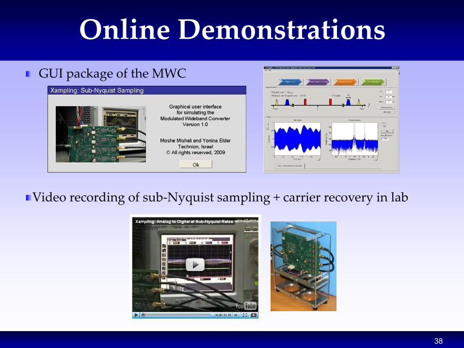
Online Demonstrations
GUI package of the MWC Video recording of sub-Nyquist sampling + carrier recovery in lab

39
SiPS 2010 2010 IEEE Workshop on
Signal Processing Systems
Demos – Supported By NI
Demo this afternoon by Rolf and Idan

40
Talk Outline
Brief overview of standard sampling
Classes of structured analog signals
Xampling: Compression + sampling
Sub-Nyquist solutions Multiband communication
Time delay estimation:
Ultrasound, radar, multipath medium identification
Applications to digital processing

41
Streams of Pulses
is replaced by an integrator
Can equivalently be implemented as a single channel with
Application to radar, ultrasound and general localization problems such as GPS
(Gedalyahu, Tur, Eldar 10, Tur, Freidman, Eldar 10)

42
Unknown Pulses
Output corresponds to aliased version of Gabor coefficients Recovery by solving 2-step CS problem
Row-sparse Gabor Coeff.
(Matusiak and Eldar, 11)

43
Noise Robustness
0 10 20 30 40 50 60 70 80 90
-100
-80
-60
-40
-20
0
20
40
SNR [dB]
MS
E [
dB
]
proposed method
integrators
0 10 20 30 40 50 60 70 80 90
-100
-80
-60
-40
-20
0
20
40
SNR [dB]
MS
E [
dB
]
proposed method
integrators
L=2 pulses, 5 samples L=10 pulses, 21 samples
MSE of the delays estimation, versus integrators approach (Kusuma & Goyal )
The proposed scheme is stable even for high rates of innovation!

44
Application: Multipath Medium Identification
LTV channel
propagation paths
Medium identification (collaboration with National Instruments): Recovery of the time delays Recovery of time-variant gain coefficients
pulses per period
The proposed method can recover the channel parameters from sub-Nyquist samples
(Gedalyahu and Eldar 09-10)

45
Application: Wireless Communications
New paradigm for wireless communications: Joint effort with Prof. Andrea Goldsmith from Stanford (Transformative Science Grant)
Main bottleneck today in wireless are ADCs Multiuser detection, which enables many users to share joint resources, is not implemented because of high rates – channels are interference limited SDR and Cognitive radio are limited by ADCs Capacity tools are limited to Nyquist-rate channels
New multiuser receiver that substantially reduces hardware requirements Capacity expressions for sampling-rate limited channels Applications to LTE standards (with Prof. Murmann and Ericsson)

46
Each target is defined by: Range – delay Velocity – doppler
Application: Radar
(Bajwa, Gedalyahu and Eldar, 10)
Targets can be identified with infinite resolution as long as the time-bandwidth product satisfies Previous results required infinite time-bandwidth product

47
A scheme which enables reconstruction of a two dimensional image, from samples obtained at a rate 10-15 times below Nyquist
The resulting image depicts strong perturbations in the tissue
Obtained by beamforming in the compressed domain
More details in Noam’s talk
Xampling in Ultrasound Imaging
Wagner, Eldar, and Friedman, ’11
Standard Imaging Xampled beamforming
1662 real-valued samples, per sensor
per image line
200 real-valued samples, per sensor per
image line (assume L=25 reflectors per line)

48
Union of subspaces structure can be exploited in many digital models
Subspace models lead to block sparse recovery
Block sparsity: algorithms and recovery guarantees in noisy environments (Eldar and Mishali 09, Eldar et. al. 10, Ben-Haim and Eldar 10)
Hierarchical models with structure on the subspace level and within the subspaces (Sprechmann, Ramirez, Sapiro and Eldar, 10)
Structure in Digital Problems
Noisy merged Missing pixels Separated

49
Source Separation Cont.
Texture Separation:

50
Subspace Learning
Prior work has focused primarily on learning a single subspace (Vidal et. al., Ma et. al., Elhamifar …)
We developed methods for multiple subspace learning from training data (Rosenblum, Zelnik-Manor and Eldar, 10)
Subspace learning from reduced-dimensional measured data: Blind compressed sensing (Gleichman and Eldar 10)
Current work: Extending these ideas to more practical scenarios (Carin, Silva, Chen, Sapiro)

51/20
50% Missing Pixels
Interpolation by learning the basis from the corrupted image

52
Compressed sampling and processing of many signals
Wideband sub-Nyquist samplers in hardware
Union of subspaces: broad and flexible model
Practical and efficient hardware
Many applications and many research opportunities: extensions to other analog and digital problems, robustness, hardware …
Exploiting structure can lead to a new sampling paradigm which combines analog + digital
Conclusions
More details in: M. Duarte and Y. C. Eldar, “Structured Compressed Sensing: From Theory to Applications,” Review for TSP. M. Mishali and Y. C. Eldar, "Xampling: Compressed Sensing for Analog Signals", book chapter available at http://webee.technion.ac.il/Sites/People/YoninaEldar/books.html

53
Xampling Website
webee.technion.ac.il/people/YoninaEldar/xampling_top.html
Y. C. Eldar and G. Kutyniok, "Compressed Sensing: Theory and Applications", Cambridge University Press, to appear in 2012

54
Thank you