deformation/displacement measurement using 3d laser scanning · • total stations were removed...
TRANSCRIPT

Deformation/Displacement Measurement Using 3D
Laser Scanning
Research Team Leaders
Dr. Fatih Oncul, Ph.D., Dr. Wasim Barham, Ph.D.
Data Collection Teams
Point Cloud Scanner - Dr. Pavan Meadati, Ph.D.
Total Station - John M. Lee, RLS, Daniel Branham, RLS
Displacement Gauge – William Lotz, Chance Dennis
January 26, 2012

Deformation/Displacement Measurement Using 3D Laser Scanning
• Introduction (Mr. Lee) 5 min
• Participants & Companies
• Project Overview
– Research topic (Dr. Oncul, Dr. Barham) 20 min
• Q&A 5min
– Surveyors involvement (Mr. Lee, Mr. Branham) 20 min
• Pre-project Discussions & Engagement Agreements
• Q&A 5min
• Outcomes and Metrics
– Data collection outcome (All) 20 min
– ROI calculations
– Q&A 5min
• Conclusions / Recommendations (All) 10-15 min
AGENDA

Deformation/Displacement Measurement Using 3D Laser Scanning

Deformation/Displacement Measurement Using 3D Laser Scanning
Deformation/Displacement Measurement Using 3D Laser Scanning

Deformation/Displacement Measurement Using 3D Laser Scanning
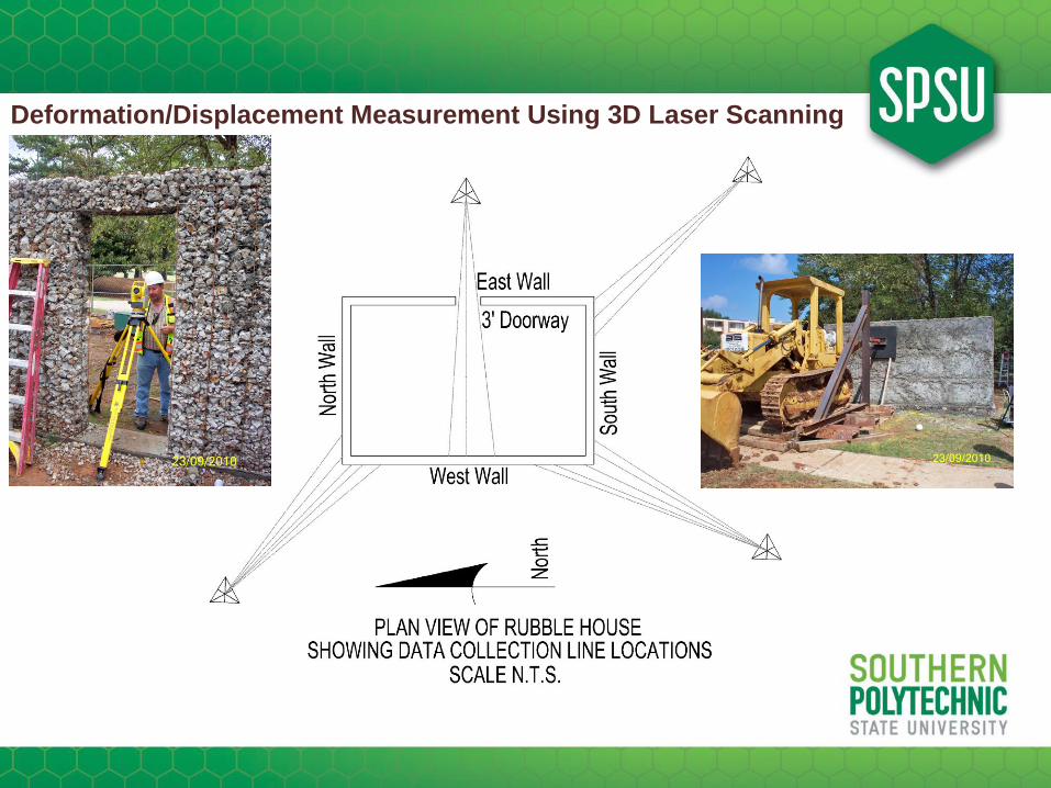
• Client Request
– Researchers Project Topic• The Structural Properties of the Conscience International Rubble House Building Technique
– Data Collection Team Proposals
• Repeatable Techniques / Data Integrity
– Performance Requirements
– Data Collection and Validation Requirements
• Actions Taken / To-be Taken
– Taken: Engagement of three data collection teams
– Taken: Project schedule set
– Taken: Data Collection completed
– To-be Taken: Final Analysis Report presentation to ASCE
• Safety Items / Concerns
PROJECT OVERVIEW
Deformation/Displacement Measurement Using 3D Laser Scanning
• Expected Number of Data Points to be collected for Analysis
• Safety / Site Requirements
• Cost ( Time and Materials / „Not To Exceed‟ Pricing )
– Labor
– Equipment
• Project Time Frames
• Quality / Attention to Detail
– Research Level Data Collection Work
– Data Collection Opportunities will only occur once, cannot go back and get it later
PRE-ENGAGEMENT DISCUSSIONS
Deformation/Displacement Measurement Using 3D Laser Scanning
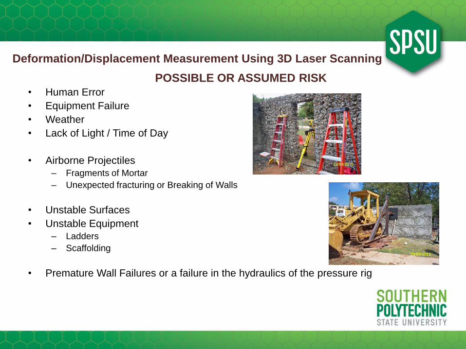
• Human Error
• Equipment Failure
• Weather
• Lack of Light / Time of Day
• Airborne Projectiles
– Fragments of Mortar
– Unexpected fracturing or Breaking of Walls
• Unstable Surfaces
• Unstable Equipment
– Ladders
– Scaffolding
• Premature Wall Failures or a failure in the hydraulics of the pressure rig
POSSIBLE OR ASSUMED RISK

Deformation/Displacement Measurement Using 3D Laser Scanning
• Technicians Job Performance Responsibilities
– Safety Practices to follow
– Site Safety Practices
• Required Equipment
– Safety Vest
– Work Gloves
– Hardhat
– Steel Toed Boots
– Safety Glasses / Goggles
– Boundary Tape
• Laser Eye Protection
SAFETY
Deformation/Displacement Measurement Using 3D Laser Scanning
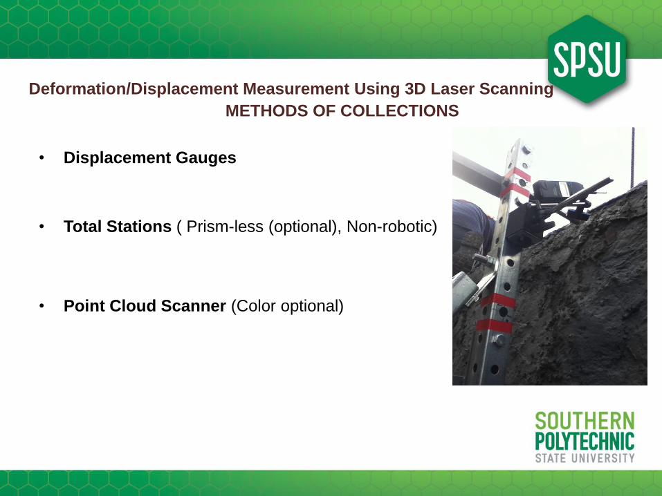
• Displacement Gauges
• Total Stations ( Prism-less (optional), Non-robotic)
• Point Cloud Scanner (Color optional)
METHODS OF COLLECTIONS

Deformation/Displacement Measurement Using 3D Laser Scanning
• Displacement Gauges
• Total Stations ( Prism-less (optional), Non-robotic)
• Point Cloud Scanner (Color optional)
METHODS OF COLLECTIONS

Deformation/Displacement Measurement Using 3D Laser Scanning
• Displacement Gauges
• Total Stations ( Prism-less (optional), Non-robotic)
• Point Cloud Scanner (Color optional)
METHODS OF COLLECTIONS

Deformation/Displacement Measurement Using 3D Laser Scanning
Question and Answer Session

A Rubble House is…
• a structure with walls made out of wire
baskets filled with loose rubble
• environmentally friendly (recycles concrete
rubble)

A Rubble House is…
• a permanent house for the needy
• an alternate temporary emergency
shelter for disaster areas

A Rubble House is…
• built with simple tools, easily available materials, and local labor.
• earthquake resistant ???

Demonstrations with Concrete Battering Ram.
Brick Wall Rubble Wall

Conscience International

Research Phases
• Phase 1: Preliminary, static loading, sponsored
locally, @ SPSU
• Phase 2: Comprehensive, full-scale shake table
test(s), sponsored by NSF? @ University of
Buffalo?

Objectives of Phase 1
• Evaluate current construction techniques and propose
cost-effective improvements
• Perform static load testing on a full-scale RUBBLE-HOUSE
• Create computer models for static and dynamic analyses
• Make recommendations for future seismic shake table
experiments
• Draft construction and design guidelines based on
experimental and numerical findings

Static Field Load Testing Schedule - Phase 1
Test 1 Test 2
Test 3
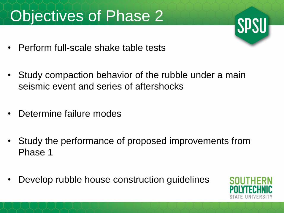
Objectives of Phase 2
• Perform full-scale shake table tests
• Study compaction behavior of the rubble under a main
seismic event and series of aftershocks
• Determine failure modes
• Study the performance of proposed improvements from
Phase 1
• Develop rubble house construction guidelines
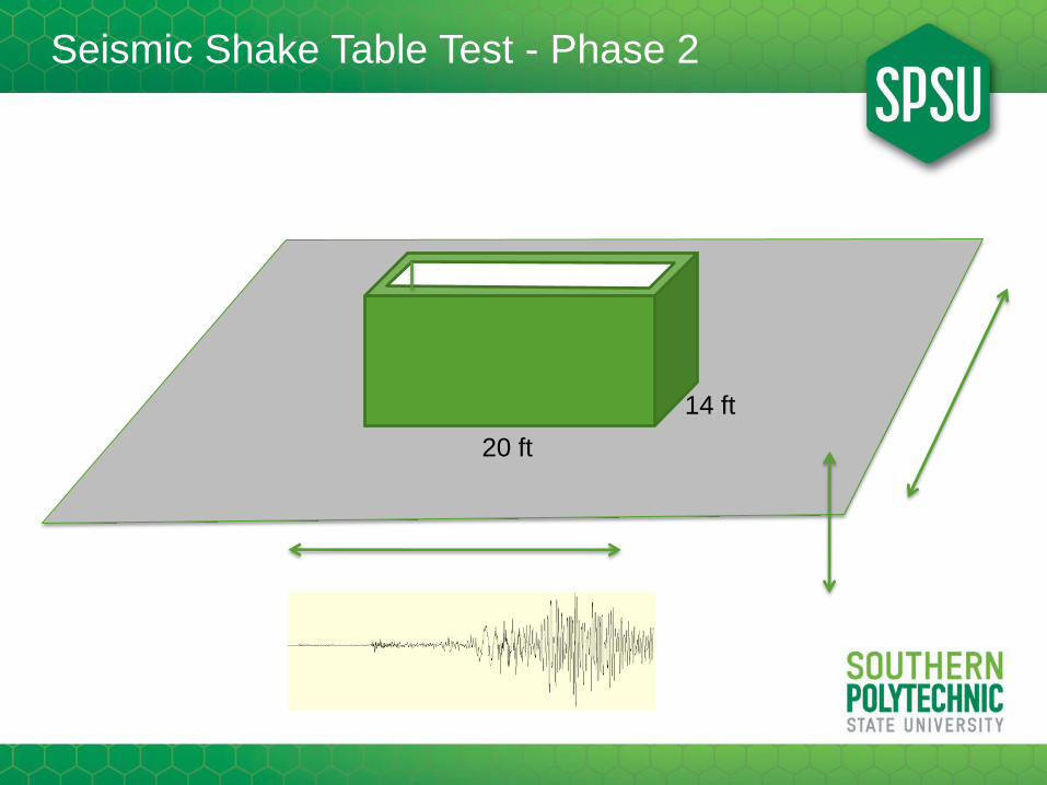
Seismic Shake Table Test - Phase 2
20 ft
20 ft
14 ft

• Three Methods
– Disp. gauges
– Total Stations
– 3D Laser
• Expectations
– Be able to measure small
displacements
– Required precision: 0.01 in
– Capture displacements during
unloading
– Cost
Measurements

Displacement/Deformation Gages
Displacement gage
Deformation gage
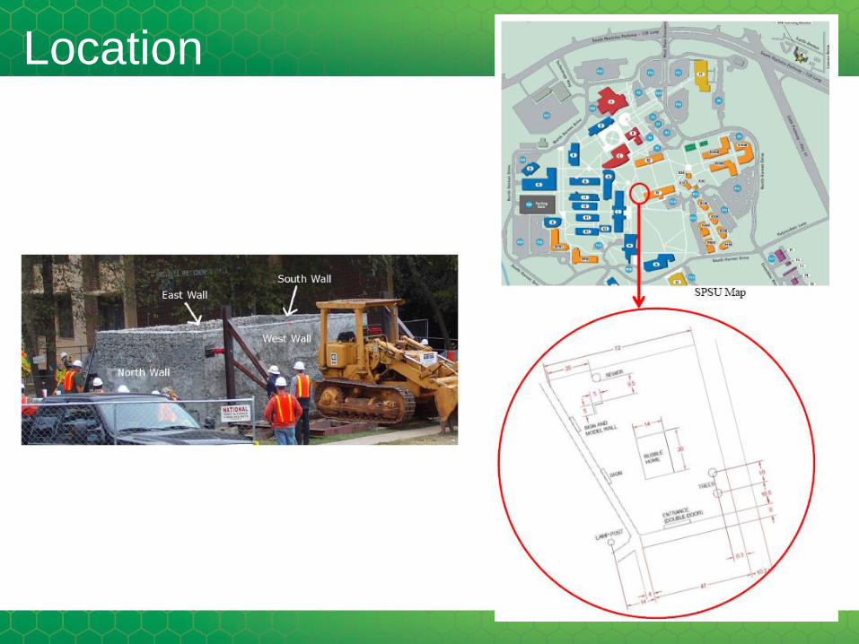
Location

In Haiti

At SPSU

Student Involvement
• More than 100 students participated..
• 600 hours of student labor time..

• In-plane push
TEST 1

• Center push
TEST 2

3D Laser Scan Picture – Test 2: Center Push
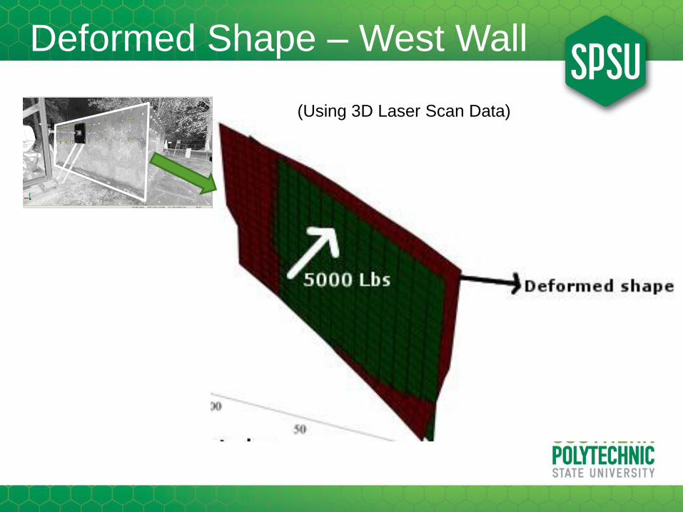
Deformed Shape – West Wall
(Using 3D Laser Scan Data)

Exterior Surface
Interior Surface
COMPARISON OF
MEASURED DATA(West Wall)
P=5000 kips

• Destructive
TEST 3
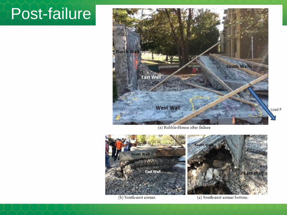
Post-failure

3D Laser Scan Picture – Test 3: Destructive

Deformed Shape – South Wall(Using 3D Laser Scan Data)
P= 6 kips P= 12 kips P= 15
kips
(Base slide was initiated when P ~ 15 Kips)
P

ATS – Applied Technical Services
Marietta, GA

Other Sponsors
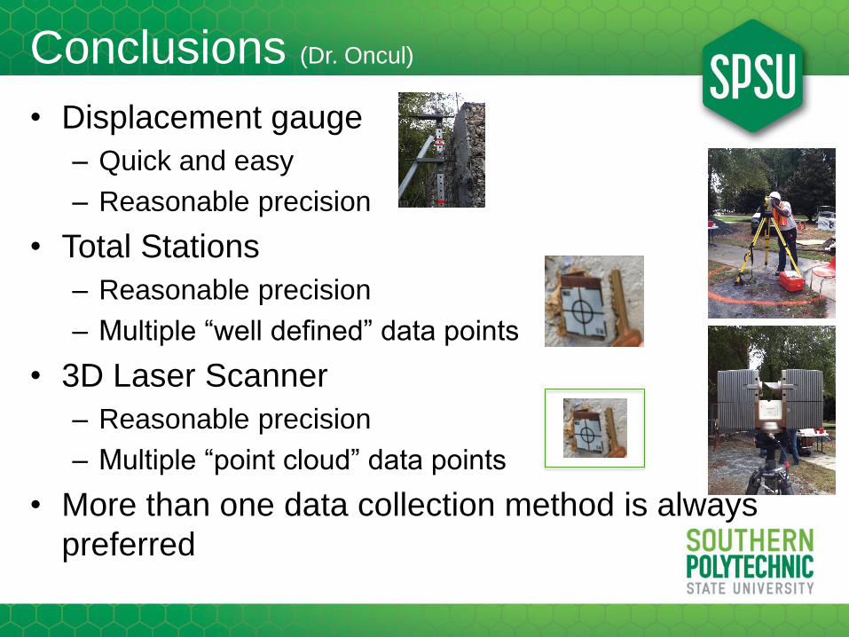
Conclusions (Dr. Oncul)
• Displacement gauge
– Quick and easy
– Reasonable precision
• Total Stations
– Reasonable precision
– Multiple “well defined” data points
• 3D Laser Scanner
– Reasonable precision
– Multiple “point cloud” data points
• More than one data collection method is always
preferred

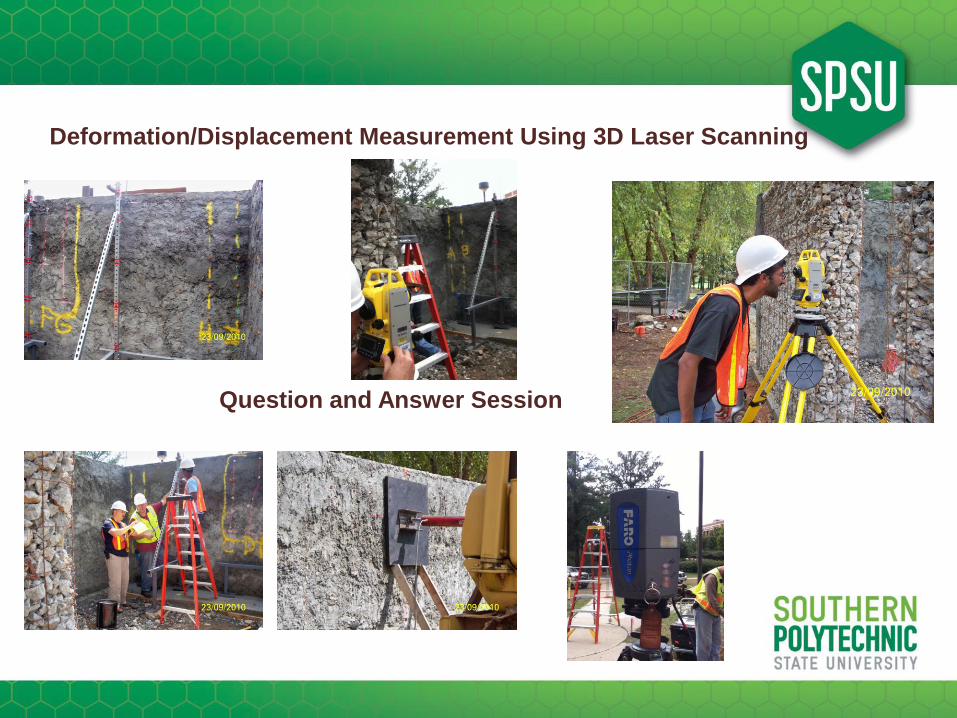
Deformation/Displacement Measurement Using 3D Laser Scanning
Question and Answer Session
Deformation/Displacement Measurement Using 3D Laser Scanning
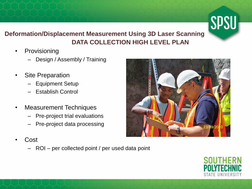
• Provisioning
– Design / Assembly / Training
• Site Preparation
– Equipment Setup
– Establish Control
• Measurement Techniques
– Pre-project trial evaluations
– Pre-project data processing
• Cost
– ROI – per collected point / per used data point
DATA COLLECTION HIGH LEVEL PLAN
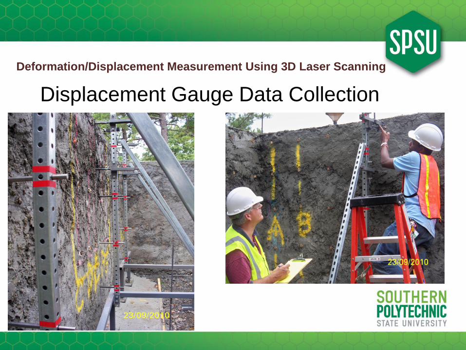
Deformation/Displacement Measurement Using 3D Laser Scanning
Displacement Gauge Data Collection
Deformation/Displacement Measurement Using 3D Laser Scanning
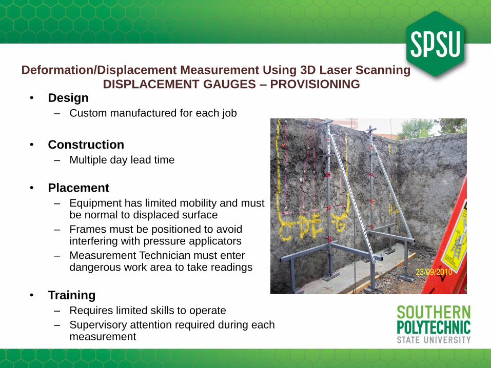
• Design
– Custom manufactured for each job
• Construction
– Multiple day lead time
• Placement
– Equipment has limited mobility and must be normal to displaced surface
– Frames must be positioned to avoid interfering with pressure applicators
– Measurement Technician must enter dangerous work area to take readings
• Training
– Requires limited skills to operate
– Supervisory attention required during each measurement
DISPLACEMENT GAUGES – PROVISIONING

Deformation/Displacement Measurement Using 3D Laser Scanning
• Establish Control
• Equipment Placement
– Determine the Area of Operation
– Range of Valid Data / Tolerance of Calipers
– Placement of Ladders, Scaffolding, and target measurement areas
– Labeling of Surfaces, Targets
• Setup of Hardware
– Pre-trial testing
• Simulated Data Collection
• Data processing
• Ladders, Lights, technician placement
• Tie to Control Procedures
– Frames should be located and tied to structure, total station and point cloud control points
DISPLACEMENT GAUGES – SITE PREPARATION
Deformation/Displacement Measurement Using 3D Laser Scanning
• Pre-trial data collection evaluation
– Set displacement gauges to starting position
– Set measurement calipers to zero position
– Displace gauge using a fixed size object
– Read, record and validate the starting / benchmark values
– Ensure that no movement has occurred in frame of displacement gauge
• Pre-trial data processing evaluation
– Using recorded values, compute the displacement
– Determine if fixed object displacement value is within tolerance to the
measured displacement
DISPLACEMENT GAUGES – MEASUREMENT TECHNIQUES
Deformation/Displacement Measurement Using 3D Laser Scanning
• Data Obtained
– Students performed construction, data collection and (Dr. Oncul) reduction
– Frames with 5 Gauges were read• 5 tests each day for 2 days
• 5 points per test session
• Measurement calipers were verified to 0.01 (inches)
– Displacement Gauge Team Work Process• 1 team of 2 persons (one measurement technician / one documentation technician)
• Data validated by taking multiple measurements, then averaging results
– Total data collected (3 frames*5 gauges*5 tests*2 days = 150 data points)
• Data collected during two of three days of testing
• Displacement gauge frames removed from work area during destructive test sequence
• All data point WERE utilized by researchers in analysis
DISPLACEMENT GAUGES – OUTCOME / RESULTS

Deformation/Displacement Measurement Using 3D Laser Scanning
• Costs
– Total Costs = $2,000.00
• Materials & Construction Cost ($500.00)
• Data Collection teams ($15/hr *80 hrs = $1,200.00)
• Data reduction (team & researchers) $15/hr * 20 hrs = $300.00)
– Research team ROI ($2,000 / 150 points = $13.33 / pt)
• Per collected data point
– All 150 points reviewed for validity
• Per analyzed data point
– All 150 points used for final analysis
– Displacement Gauge Team ROI
• Per collected data point ($2,000 / 300 readings = $6.67 / pt)
• Per collection period ($1,500 / 80 hours = $18.75 / hr)
• 2 technicians ($18.75 / 2 persons = $9.38 / hr)
DISPLACEMENT GAUGES – COSTS

Deformation/Displacement Measurement Using 3D Laser Scanning
Question and Answer Session

Deformation/Displacement Measurement Using 3D Laser Scanning
Total Station Data Collection

Deformation/Displacement Measurement Using 3D Laser Scanning
Total Station Data Collection
Deformation/Displacement Measurement Using 3D Laser Scanning
• Design– Use standard Non-robotic 6 second Construction total stations (Topcon Sokkia
CTS-6) equipment packages which include instrument, tripod, prism, prism pole, tribrach, tripod, sheet of 400 (10mm) Sokkia stick-on targets.
• Construction– Equipment and operators obtained from local companies
– J.A. Evans & Associates Land Surveyors– Paul Lee Consulting Engineering Associates, Inc.– Optical Engineering– SPSU
• Placement– Limited mobility, Equipment must be placed to see control and avoid
interfering with pressure applicators but pressure equipment could move during loading
– Equipment capabilities allowed for data collection from about 35 feet from work zone
• Training– Requires skilled operators to collect data– RLS attention required during each measurement session
TOTAL STATION - PROVISIONING
Deformation/Displacement Measurement Using 3D Laser Scanning
• Establish Control ahead of test session– Control Traverse Setup, Run and Validated Before Test– Reflector Targets obtained and attached to finished structure
• Equipment Placement– Determine the Area of Operation– Range of Valid Data / Tolerance of equipment– Placement of control tripods, prisms, targets– Labeling of Surfaces, Targets
• Setup of Hardware– Pre-trial testing
• Simulated Data Collection• Data processing• Lights, total stations, control points, and technician placement
• Tie to control– Surveyors performed data collection, students compiled
computations and documentation
TOTAL STATION – SITE PREPARATION

Deformation/Displacement Measurement Using 3D Laser Scanning
• Pre-trial data collection evaluation
– Set control and total stations to starting positions
– Set total station and data collectors to zero position
– Read, record and validate the starting & benchmark values
– Turn to a known second control point
– Read, record and validate the ending & elevation values
– Ensure that no movement has occurred in local or control equipment
• Pre-trial data processing evaluation
– Using recorded values, compute the displacement
– Determine if control displacement value is within tolerance to measured
displacement
TOTAL STATION – MEASUREMENT TECHNIQUES

Deformation/Displacement Measurement Using 3D Laser Scanning
• Data Obtained
– Surveyors performed setup of control, data collection; students performed documentation and data reduction
– 3 Total Stations with 3 control points were established and read• 5 tests each day for 2 days• 15 points per session• Measurements were verified to 0.06 (inches) or 0.005 (feet)
– Total Station Team Data Collection Work Process• 3 teams of 2 persons (one surveyor / one documentation technician)• Data validated by taking multiple measurements, then verifying that
results did not fall outside margin of error
– Total data collected (3 stations*15 points*5 tests*2 days = 675 data points)
• Data collected during two of three days of testing• Total Stations were removed from work area during destructive test
sequence• All data point WERE NOT utilized by researchers in analysis• Field Data Collection Errors were detected during collection
and 25 additional shots taken (total = 700)
TOTAL STATION – OUTCOME / RESULTS

Deformation/Displacement Measurement Using 3D Laser Scanning
• Costs
– Total Costs = $4,300.00• Equipment Rental Costs ($450.00 per total station package per day *
3 units * 2 days = $2,700.00)• Data Collection teams ($15/hr *80 hrs = $1,200.00)• Data reduction team & researchers ($15/hr * 20 hrs = $300.00)• Surveyor Review of data reduction ($100 /hr = $100.00)
– Research team ROI ($4,300 / 600 points = $7.17 / pt)• Per collected data point
– All 700 points reviewed for validity– 75 points were discarded due to incorrect back sight settings, 25
for operator or documentation error• Per analyzed data point
– 600 points used for final analysis
– Total Station Team ROI• Per collected data point ($4,300 / 700 readings = $6.15 / pt)• Per collection period ($4,300 / 80 hours = $53.75 / hr)• 6 technicians ($53.75 / 6 persons = $8.96 / hr)
TOTAL STATION – COSTS

Deformation/Displacement Measurement Using 3D Laser Scanning
Question and Answer Session

Deformation/Displacement Measurement Using 3D Laser Scanning
Point Cloud Scanner Data Collection

Deformation/Displacement Measurement Using 3D Laser Scanning
Deformation/Displacement Measurement Using 3D Laser Scanning
• Design• Use standard Point Cloud Scanner equipment package (Faro Focus 3D Laser
Scanner) with tripod, location markers, scanning software, SD storage card, Dell notebook computer.
• Construction– Equipment and operators obtained from local companies (Faro.com, SPSU)
• Placement– Almost unlimited mobility, although equipment must be placed to see control and
avoid interfering with pressure applicators but pressure equipment could move during loading
– Equipment capabilities allowed for data collection from about 35 feet from work zone
– Location markers cannot be moved during entire test process
– Scanner cannot be moved during scanning process
• Training– Requires skilled operators to collect data
– Eye Safety is critical and must be strictly enforced
– RLS attention required during each measurement session
POINT CLOUD SCANNER - PROVISIONING

Deformation/Displacement Measurement Using 3D Laser Scanning
POINT CLOUD SCANNER - PROVISIONING

Deformation/Displacement Measurement Using 3D Laser Scanning
POINT CLOUD SCANNER - PROVISIONING
Deformation/Displacement Measurement Using 3D Laser Scanning
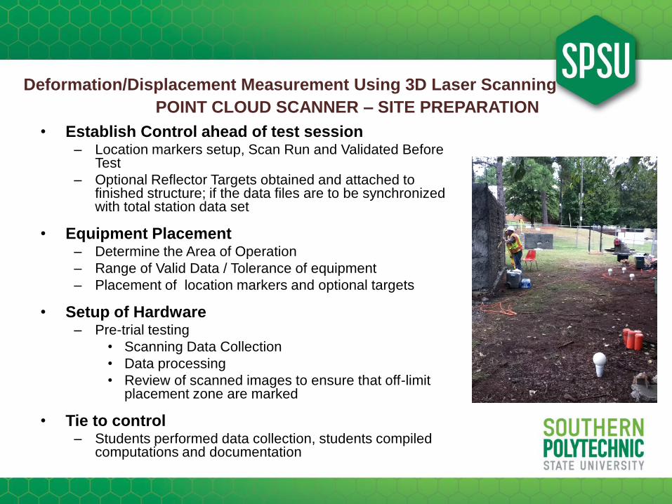
• Establish Control ahead of test session– Location markers setup, Scan Run and Validated Before
Test
– Optional Reflector Targets obtained and attached to finished structure; if the data files are to be synchronized with total station data set
• Equipment Placement– Determine the Area of Operation
– Range of Valid Data / Tolerance of equipment
– Placement of location markers and optional targets
• Setup of Hardware– Pre-trial testing
• Scanning Data Collection
• Data processing
• Review of scanned images to ensure that off-limit placement zone are marked
• Tie to control– Students performed data collection, students compiled
computations and documentation
POINT CLOUD SCANNER – SITE PREPARATION

Deformation/Displacement Measurement Using 3D Laser Scanning
• Pre-trial data collection evaluation
– Set location markers around site and position prisms on two control
points
– Scan and validate the starting & benchmark values
– Ensure that scan includes at least one of the known control point and
three of the location markers
– Process the scan image and data file
– Ensure that no movement has occurred in local or control equipment
• Pre-trial data processing evaluation
– Using recorded values, compute the displacement
– Determine if control displacement value is within tolerance to measured
displacement
POINT CLOUD SCANNER – MEASUREMENT TECHNIQUES

Deformation/Displacement Measurement Using 3D Laser Scanning
• Data Obtained– Surveyors performed setup of control markers; students placed location
markers, performed the scan data collection and students performed final documentation and data reduction
– 1 Point Cloud Scanner control area marked with 5 location spheres along with 3 control points were established and read
• 5 load increments each day for 2 days
• 3,000,000+ points per test session
• Measurements were verified to 2 (mm)
– Point Cloud Scanner Team Data Collection Work Process
• 1 teams of 2 persons (one scanner operator / one documentation technician)
• Data validated by scanner, image shown to operator at the end of the scan
– Total data collected (1scanner*3million points*5 tests*3 days = 45,000,000 data points)
• Data collected during all three days of testing
• Scanner was positioned outside the work area during destructive test sequence
• All data point WERE NOT utilized by researchers in analysis
• Initial scanner failed during pre-trial setup evaluation period, manufacturer supplied loaner
POINT CLOUD SCANNER – OUTCOME / RESULTS

Deformation/Displacement Measurement Using 3D Laser Scanning
• Costs
– Total Costs = $10,500.00• Equipment Rental Costs ($3,000.00 per scanner package per day * 3 days = $9,000.00)• Data Collection teams ($100/hr *10 hrs = $1,000.00)• Data reduction team & researchers ($100/hr * 4 hrs = $400.00)• Surveyor Review of data reduction ($100 /hr = $100.00)
– Research team ROI ($10,500 / 4500 points = $2.33 / pt)• Per collected data point
– All 45,000,000+ points reviewed for validity– Some number of points were discarded due to equipment failure during day one.
• Per analyzed data point– Of the 1,000,000 points specific to the areas under study, only 4500 of the points
were used for final analysis
– Point Cloud Scanner Team ROI• Per collected data point ($10,500 / 1,000,000 readings = $0.01 / pt)• Per collection period ($10,500 / 15 hours = $700.00 / hr)• 2 technicians and 1 Surveyor ($700 / 3 persons = $233.00 / hr)
POINT CLOUD SCANNER – COSTS
Deformation/Displacement Measurement Using 3D Laser Scanning
Question and Answer Session

Deformation/Displacement Measurement Using 3D Laser Scanning
Conclusions / Recommendations
• Researcher’s Recommendations
• Dr. Oncul / Dr. Barham / Dr. Meadati…???
• Surveyor’s Conclusions
• Am I ready to buy / rent new equipment to pursue this market?
• Point Cloud Scanning Team Conclusions
• Is this equipment really ready for survey field conditions

Deformation/Displacement Measurement Using 3D Laser Scanning
Parameters Displacement
Gauges
Total
Station
Point Cloud
Scanner
Data
Collection
Time (per pt)
6 minutes/pt(14 hrs / 150 pts)
2 minutes/pt(14 hrs / 600 pts)
16 seconds/pt(21 hrs / 4500 pts)
Skill Level
(technician)
Minimal Party Chief Skilled Data
Collection
Tech
Field Time 80 hours
- 66 hrs prep
- 14 hrs of test
observations
80 hours
- 66 hrs prep
- 14 hrs test
observations
24 hours
- 3 hrs prep
- 21 hrs test
observations
Number of Pts. 150 collected
150 used
700 collected
600 used
45,000,000+
collected
4500 used
Total
Cost
Apprx
$2,000 / job
Apprx
$4,300/job
Apprx
$10,000/job

Deformation/Displacement Measurement Using 3D Laser Scanning
Question and Answer Session
Deformation/Displacement Measurement Using 3D Laser Scanning
Thank You for your attention to our presentation!