defining the work flow - computers and structuresdocs.csiamerica.com/manuals/safe/safe defining the...
TRANSCRIPT

Defining the Work Flow

S A F E ®
DESIGN OF SLABS, BEAMS AND FOUNDATIONIS REINFORCED AND POST-TENSIONED CONCRETE
Defining the Work Flow
ISO SAF112816M2 Rev. 0 Proudly developed in the United States of America
November 2016

Copyright
Copyright Computers & Structures, Inc., 1978-2016 All rights reserved. The CSI Logo® and SAFE® are registered trademarks of Computers & Structures, Inc. Watch & LearnTM is a trademark of Computers & Structures, Inc. Adobe and Acrobat are registered trademarks of Adobe Systems Incorported. AutoCAD is a registered trademark of Autodesk, Inc. The computer program SAFE® and all associated documentation are proprietary and copyrighted products. Worldwide rights of ownership rest with Computers & Structures, Inc. Unlicensed use of this program or reproduction of documentation in any form, without prior written authorization from Computers & Structures, Inc., is explicitly prohibited.
No part of this publication may be reproduced or distributed in any form or by any means, or stored in a database or retrieval system, without the prior explicit written permission of the publisher.
Further information and copies of this documentation may be obtained from:
Computers & Structures, Inc. www.csiamerica.com [email protected] (for general information) [email protected] (for technical support)

DISCLAIMER
CONSIDERABLE TIME, EFFORT AND EXPENSE HAVE GONE INTO THE DEVELOPMENT AND TESTING OF THIS SOFTWARE. HOWEVER, THE USER ACCEPTS AND UNDERSTANDS THAT NO WARRANTY IS EXPRESSED OR IMPLIED BY THE DEVELOPERS OR THE DISTRIBUTORS ON THE ACCURACY OR THE RELIABILITY OF THIS PRODUCT.
THIS PRODUCT IS A PRACTICAL AND POWERFUL TOOL FOR STRUCTURAL DESIGN. HOWEVER, THE USER MUST EXPLICITLY UNDERSTAND THE BASIC ASSUMPTIONS OF THE SOFTWARE MODELING, ANALYSIS, AND DESIGN ALGORITHMS AND COMPENSATE FOR THE ASPECTS THAT ARE NOT ADDRESSED.
THE INFORMATION PRODUCED BY THE SOFTWARE MUST BE CHECKED BY A QUALIFIED AND EXPERIENCED ENGINEER. THE ENGINEER MUST INDEPENDENTLY VERIFY THE RESULTS AND TAKE PROFESSIONAL RESPONSIBILITY FOR THE INFORMATION THAT IS USED.

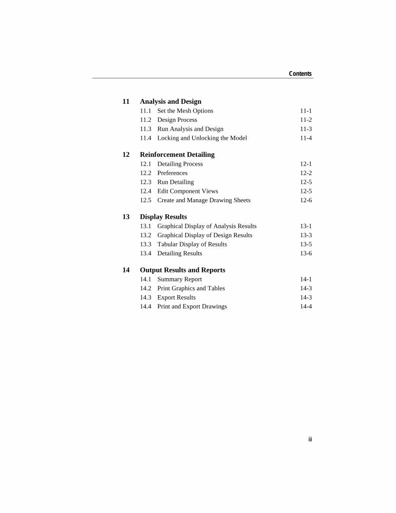
Contents
1 Set the Units 1-1
2 Start a Model 2.1 Begin a Model Using a Basic Grid System 2-1 2.2 Begin a Model Using Templates 2-4 2.3 Begin a Post-Tensioned Model Using
Templates 2-6 2.4 Import a Model from ETABS 2-7 2.5 Saving a Model 2-8
3 Define Materials 3.1 Modify Existing Materials 3-1 3.2 Input New Materials 3-3
4 Define Properties 4.1 Input Structural and Support Properties 4-1
5 Draw Objects 5.1 Draw Slabs/Areas 5-1 5.2 Draw Rectangular Slabs/Areas 5-3 5.3 Quick Draw Slabs/Areas 5-4 5.4 Quick Draw Areas Around Points 5-5
i

SAFE – Defining the Work Flow
5.5 Draw Design Strips 5-6 5.6 Draw Beams/Lines 5-7 5.7 Quick Draw Beams/Lines 5-7 5.8 Draw Tendons 5-8 5.9 Draw Columns 5-10 5.10 Draw Walls 5-11 5.11 Draw Dimension Lines 5-12 5.12 Draw Slab Rebar 5-12
6 Select Objects 6.1 Selection by Graphical Methods 6-1 6.2 Selection by Features 6-4 6.3 Deselect 6-5 6.4 Invert Selection 6-5 6.5 Get Previous Selection 6-6 6.6 Clear Selection 6-6
7 Assign Properties to the Model 7-1
8 Load the Model 8.1 Define Load Patterns 8-1
8.1.1 Self Weight Multiplier 8-2 8.1.2 Auto Live Load Patterning 8-3
8.2 Assign Loads 8-3 8.3 Define Mass Source 8-4
9 Define Load Cases 9.1 Review/Create Load Cases 9-1
10 View and Edit the Model Geometry 10.1 Changing Views 10-1 10.2 Editing Tools 10-2
10.2.1 Interactive Database Editing 10-3
ii
Contents
11 Analysis and Design 11.1 Set the Mesh Options 11-1 11.2 Design Process 11-2 11.3 Run Analysis and Design 11-3 11.4 Locking and Unlocking the Model 11-4
12 Reinforcement Detailing 12.1 Detailing Process 12-1 12.2 Preferences 12-2 12.3 Run Detailing 12-5 12.4 Edit Component Views 12-5 12.5 Create and Manage Drawing Sheets 12-6
13 Display Results 13.1 Graphical Display of Analysis Results 13-1 13.2 Graphical Display of Design Results 13-3 13.3 Tabular Display of Results 13-5 13.4 Detailing Results 13-6
14 Output Results and Reports 14.1 Summary Report 14-1 14.2 Print Graphics and Tables 14-3 14.3 Export Results 14-3 14.4 Print and Export Drawings 14-4
iii

Chapter 1 Set the Units
This chapter describes how to set the database units.
The units for a new model are set by clicking on the units Modify/Show button on the New Model Initialization form (see Chapter 2), or for an existing model, by clicking the Options menu > Units command or the Units button located in the lower right-hand corner of the SAFE win-dow. Any of those actions will display the Units form shown in Figure 1-1. Use that form to set the units for all input, output, and display val-ues. Quick unit selection buttons instantly set all unit values to US de-faults, Metric defaults, or to Consistent values. The units for individual items may be changed by clicking in the associated units edit box and se-lecting units from the drop-down list.
The units selected for a particular item in the Units form will be dis-played adjacent to the item’s edit box when doing input. To use units for inputting an item other than those selected in the Units form, enter the unit designation in the edit box. For example, assume that the length unit for section dimensions is set to inch in the Units form, but when entering the thickness for a mat foundation slab object, you wish to use feet. To do this, simply type “3ft” in the edit box; the program will automatically convert this value to 36 inches.
Set the Units 1 - 1

SAFE – Defining the Work Flow
Figure 1-1 Units drop-down list
The units selected for display items in the Units form will be shown in the display window title bar and adjacent to cursor values. To change the display units, use the Options menu > Units command or the Units but-ton to access the Units form and select units for the display item; the display window will be updated after the Units form is closed.
Although any units may be used at any time while working with the model, e.g., inch units for beam sections and feet units for grid layout, it is important to select an appropriate unit set before starting the model to reduce the possibility of round-off error. In other words, if work is being completed primarily in US units, US default units should be selected as the initial units. In such a case, Metric defaults would not be a good choice for the units because a conversion would always be required when saving the model, which could result in numerical variations.
1 - 2 Set the Units
Chapter 2 Start a Model
This chapter describes how to create a SAFE model using:
A basic grid system
One of the built-in templates
A model exported from ETABS
These three options give a great deal of flexibility in choosing the meth-od that is best suited to each project. As Building Information Modeling (BIM) software becomes more tightly integrated into the development of structural models, the advantages of importing a slab from the BIM-compatible-program ETABS become even more significant. Loading and properties can be assigned and applied to any slab model regardless of the method used to create it.
2.1 Begin a Model Using a Basic Grid System
Begin creating a grid system by clicking the File menu > New Model command or the New Model button. The form shown in Figure 2-1 will display.
Begin a Model Using a Basic Grid System 2- 1

SAFE – Defining the Work Flow
Figure 2-1 New Mode Initialization form
The New Model Initialization form contains a grid only button, five slab templates, one base mat template, and two templates for footings, as well as the option to start a model with a “blank” screen. To start a model us-ing a grid system only, set the desired default units by clicking the Units Modify/Show button on the New Model Initialization form, and then click the Grid Only button. The Coordinate System Definition form shown in Figure 2-2 will display.
The Coordinate System Definition form is used to specify the number of horizontal grid lines and their spacing. To obtain a uniform grid, simply specify the number of grid lines in the X and Y directions and the grid spacing for those lines. Note that the uniform spacing in the X and Y di-rections may be different. This option defines a grid system for the glob-al coordinate system only. Changes to the labels and spacing of the grid lines may be made while in the Coordinate System Definition form by clicking the Grid Labels or Edit Grid buttons, respectively. Click the OK button to accept the input made on the form, or click Cancel to can-cel the input.
2 - 2 Begin a Model Using a Basic Grid System

Start a Model
Figure 2-2 Coordinate System Definition form
To alter the spacing and labels of the grid lines after the grids have been generated, click the Define menu > Coordinate Systems command. This will display the Coordinate Systems form. Select the grid to be edit-ed, and click the Modify/Show System button to display the Coordinate System form shown in Figure 2-3, which has options for changing grid labels and spacing for each grid line in the X or Y directions, as well as specifying general grid lines. The form also has options related to how the grid lines display, including an option to make the grid lines invisi-ble. A reference “datum” elevation also may be specified, which is use-ful when analyzing multiple floors from the same building.
The definition of a grid system is important for the following reasons:
Objects snap to grid lines when drawn in the model; thus, grid lines should be defined accurately so that the placement of objects can be completed efficiently.
Objects mesh at their intersections with grid lines.
Begin a Model Using a Basic Grid System 2 - 3

SAFE – Defining the Work Flow
The grid lines in the model can be defined with the same names as are used on the building plans, allowing for easier identification of specif-ic locations in the model.
Figure 2-3 Change grid labels and spacing using the Coordinate System form
2.2 Begin a Model Using Templates
SAFE also has an option to begin a model using templates. Begin a model using templates by following the same procedure used to start a model with only a grid, namely clicking the File menu > New Model command. The New Model Initialization form shown in Figure 2-1 will again display.
2 - 4 Begin a Model Using Templates

Start a Model
Template models provide a quick, easy way of starting a model. They automatically add structural objects with appropriate properties to a model. It is highly recommended that you start your models using tem-plates whenever possible.
Choose any of the templates by clicking the associated button. When a template button is clicked, a form for that template will display. Use the form to specify various data for the template model, such as plan dimen-sions and spacing, slab or mat thicknesses, loads, and column dimen-sions.
Important Note: When using the templates, beams and ribs are modeled using depths equal to the dimension from the top of the slab to the bot-tom of the beam or rib. Beams are modeled as line objects, while ribs are modeled using equivalent slab properties.
After specifying data for a template, the model will appear in the display window. The default display will show a “Plan View,” as shown in Fig-ure 2-4.
FFigure 2-4 An active Plan View (as indicated by the highlighted title bar)
of a template model
Begin a Model Using Templates 2 - 5

SAFE – Defining the Work Flow
The Model Explorer, containing all of the model definition data, also will be displayed to the left of the plan view. Use the Options menu > Windows command to change the number of windows displayed.
Note that the Plan View is active in Figure 2-4. When a window is active, the display title bar is highlighted. Set a view active by clicking anywhere in the view window.
2.3 Begin a Post-Tensioned Model Using Templates
The steps necessary to begin a post-tensioned model from the templates are the same as outlined in the previous section, with the addition that the Add P/T check box on the Flat Slab template data form must be checked. Click the P/T Data button to display the form shown in Figure 2-5 and define the post-tensioning data to be used in the initial model. Note that post-tensioning currently is available for the flat slab template only, although tendons can be added manually to any model.
Figure 2-5 Define initial post-tensioning data
using the Quick Tendon Layout form
2 - 6 Begin a Post-Tensioned Model Using Templates
Start a Model
The Quick Tendon Layout form allows the definition of the tendon lay-out type, band width or spacing, property, and vertical profile, along with the desired precompression level and amount of self-weight load balancing.
The methodology used for the final determination of the tendon vertical profiles and other post-tensioning design capabilities is described in de-tail in the Post-Tensioning Concrete Design manual.
2.4 Import a Model from ETABS
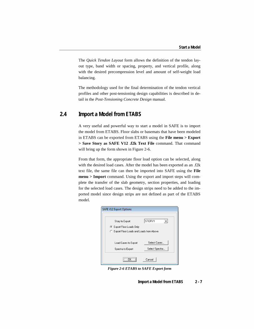
A very useful and powerful way to start a model in SAFE is to import the model from ETABS. Floor slabs or basemats that have been modeled in ETABS can be exported from ETABS using the File menu > Export > Save Story as SAFE V12 .f2k Text File command. That command will bring up the form shown in Figure 2-6.
From that form, the appropriate floor load option can be selected, along with the desired load cases. After the model has been exported as an .f2k text file, the same file can then be imported into SAFE using the File menu > Import command. Using the export and import steps will com-plete the transfer of the slab geometry, section properties, and loading for the selected load cases. The design strips need to be added to the im-ported model since design strips are not defined as part of the ETABS model.
Figure 2-6 ETABS to SAFE Export form
Import a Model from ETABS 2 - 7

SAFE – Defining the Work Flow
2.5 Saving a Model
It is good practice to save your model often. To save the model, click the File menu > Save command or the Save button. The first time the model is saved, SAFE will prompt for a file name using the Save Model File As form. An auto-save increment can be specified using the Options menu > Auto Save Model command. Note that auto-save is turned off by default because after the model is saved, the undo history is reset and SAFE remembers only steps taken since the last save.
2 - 8 Saving a Model

Chapter 3 Define Materials
Materials are named entities that are referenced by slab, beam, column, wall, and tendon properties and slab rebar objects. Materials define properties such as the modulus of elasticity, Poisson’s ratio, and material strengths.
3.1 Modify Existing Materials
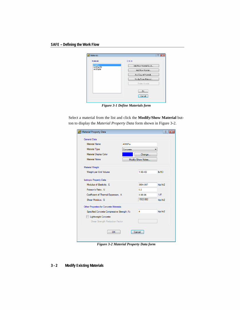
Default and previously defined materials may be reviewed using the Define menu > Materials command to display the Materials form shown in Figure 3-1.
Modify Existing Materials 3 - 1
SAFE – Defining the Work Flow
Figure 3-1 Define Materials form
Select a material from the list and click the Modify/Show Material but-ton to display the Material Property Data form shown in Figure 3-2.
Figure 3-2 Material Property Data form
3 - 2 Modify Existing Materials

Define Materials
Alternatively, this form also could be displayed by expanding the Mate-rials item located in the Model Explorer window, and then double click-ing on the appropriate material property. Modify any of the properties as needed, and then click the OK button to accept the changes made on the form, or click Cancel to cancel the changes.
3.2 Input New Materials
To input a new material property, click the Define menu > Materials command to again display the Materials form shown in Figure 3-1. Click the Add New Material Quick button to display the Quick Material Def-inition form shown in Figure 3-3. Use the form to select concrete, rebar, tendon, or steel properties from common specifications.
Figure 3-3 Quick Material Definition form
If the material required does not exist on the Quick Material Definition form, click the Cancel button and return to the Materials form. Next, click the Add New Material button, which will display the Material Property Data form similar to that shown in Figure 3-2. On the Material Property Data form, any material property values may be specified. Click the OK button to accept the changes and save the new material, or click Cancel to cancel the material property definition.
Input New Materials 3 - 3

Chapter 4 Define Properties
Properties are defined to reflect the structural behavior of point, line, and area objects in the model. Properties may be structural objects, such as slabs and columns, or supports, such as soil springs.
4.1 Input Structural and Support Properties
Structural properties, that is, slab, beam, tendon, column, and wall prop-erties that contain section definitions, are named entities that must be specified using the commands on the Define menu before assigning them to the model, as described later in this chapter and in Chapter 7. If you use a property in a model, for example a beam or column property, any changes to the definition of the property will automatically apply to the model. A named property has no effect unless it is used in the model.
Spring support properties (i.e., point, line, and soil) may be assigned to point, beam, and slab objects, and similar to structural properties, they are named entities that must be specified before they are assigned.
Table 4-1 identifies the structural and spring support property subcom-mands on the Define menu, the type of object to which the definition
Input Structural and Support Properties 4 - 1

SAFE – Defining the Work Flow
can be applied, and the form used to complete the definition. Context sensitive help is available by pressing the F1 keyboard function key when the forms are displayed.
TABLE 4-1 Property Definitions
Property Object Type Input Form
Slab Properties (Drop, Stiff, Mat) Slab/Area Slab Property Data
Beam Properties Beam/Line Beam Property Data
Tendon Properties Tendon Tendon Property Data
Column Properties Column/Brace Column Property Data
Wall Properties Wall/Ramp Wall Property Data
Soil Subgrade Properties Area Soil Subgrade Property Data
Point Spring Properties Point Point Spring Property Data
Line Spring Properties Line Line Spring Property Data
The input forms identified in Table 4-1 are preceded by standard forms that have options to add new definitions, add a copy of an existing defi-nition, modify or review existing definitions, and delete existing defini-tions. Each property definition should have a unique name that is user-defined or should use the program-suggested name. It is important that the names make it easy to assign them to the various objects correctly.
Depending on the type of property, the input forms may include user-defined analysis and design parameters, such as thicknesses, top and bot-tom cover, spring constants, and other parameters. In addition to those items, the Slab Property Data form also has a parameter for specifying the type of slab (e.g., slab, waffle, drop), which controls not only the analysis formulation, but also the design and detailing.
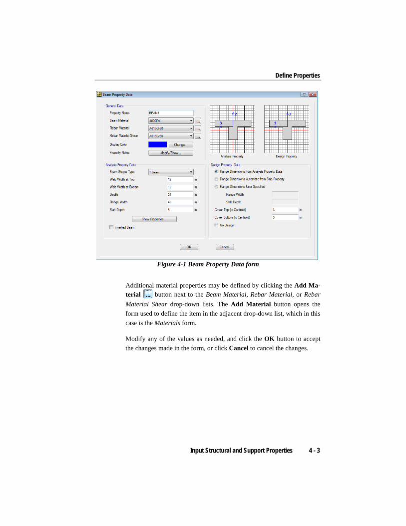
Previously defined properties, either structural or spring support, also may be accessed through the Model Explorer window. Expand the de-sired item and double click on the appropriate property to display the as-sociated input form. As an example, to review a previously defined beam property, expand the Beam Properties item, and then double click on the appropriate beam property to display the Beam Property Data form shown in Figure 4-1.
4 - 2 Input Structural and Support Properties
Define Properties
Figure 4-1 Beam Property Data form
Additional material properties may be defined by clicking the Add Ma-terial button next to the Beam Material, Rebar Material, or Rebar Material Shear drop-down lists. The Add Material button opens the form used to define the item in the adjacent drop-down list, which in this case is the Materials form.
Modify any of the values as needed, and click the OK button to accept the changes made in the form, or click Cancel to cancel the changes.
Input Structural and Support Properties 4 - 3

Chapter 5 Draw Objects
Slab, beam, tendon, column, wall, and point objects are used in SAFE to represent the slab or mat structure. Properties are defined and assigned to the model to reflect the structural characteristics. These objects can be added to any model regardless of how the model was initially created. The Draw commands allow customization and editing of any model.
5.1 Draw Slabs/Areas
Slabs or areas are used most commonly to create the main slabs (includ-ing footings and mats) or openings in slabs. To draw a slab object, activate the Plan View. Click the Draw Slabs/Areas button or select the Draw menu > Draw Slabs/Areas command to bring up the form shown in Figure 5-1.
Figure 5-1 Draw Slabs/Areas floating form
Draw Slabs/Areas 5 - 1

SAFE - Defining the Work Flow
Note: This chapter makes frequent reference to forms that "float." That is, a form remains visible when the cursor is moved over the model and the mouse button is clicked in the active window. Because the form re-mains visible, changes can be made to it without reusing the command required to access it, which differs from most forms in the program. Floating forms are used in the draw mode so that the parameters for the object being drawn can be changed easily during drawing operations. Also note that only one floating form can be visible at a time (i.e., Draw Slabs/Areas, Draw Rectangular Slabs/Areas, Draw Beams/Lines and so on.)
The floating form provides a Property drop-down list of the previously defined properties (see Chapter 4) that reflect the slab/area object to be drawn next. To change an entry on the form, click on it and make a new selection from the drop-down list or type new information into the edit box, as appropriate.
TIP: If the slab/area object is to be drawn using grid lines, ensure that the appropriate snap options are active by clicking the Draw menu > Snap Options command to display the Snap Options form shown in Figure 5-2. On that form, verify that the Grid Intersections and Points boxes are checked; this is the default setting. Click the OK button to ac-cept the settings, or the Cancel button to exit without saving any chang-es made.
Snap options help make creating a model simple. Along with specific types of snap options, such as endpoints, intersections, and the like, there also are intelligent snaps that locate nearby objects and provide snap di-mensions. The snaps can be turned on or off by using the Snap but-ton in the left toolbar.
With the parameters in the Draw Slabs/Areas floating form set, click the left mouse button once at a grid intersection (or any other position in the Plan View) to begin the area object at that location. Next, move around the perimeter of the area object, clicking once at additional locations, to draw the outline of the object. Press the Enter key on the keyboard to complete the drawing of the object.
5 - 2 Draw Slabs/Areas

Draw Objects
If a mistake is made while drawing the object, click the Select Object button to change from Draw mode to Select mode. Next, click the
Edit menu > Undo Area Add command to remove the area object just drawn. Note that the floating form disappears (closes) when the Select Object button is clicked. It is also possible, while still in the draw mode, to undo the last point defined for the area/slab object by pressing the Backspace key on the keyboard.
Figure 5-2 Snap Options form
5.2 Draw Rectangular Slabs/Areas
The Draw Slabs/Areas command previously described generates slab/area objects that can be of arbitrary shape with three or more sides. Often, slab systems are rectangular and can be quickly drawn by clicking
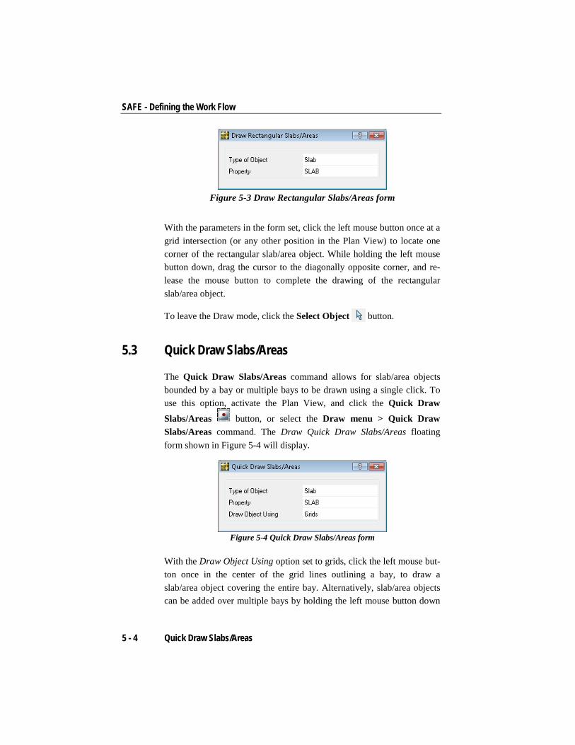
the Draw Rectangular Slabs/Areas button, or by selecting the Draw menu > Draw Rectangular Slabs/Areas command. The Draw Rectangular Slabs/Areas floating form shown in Figure 5-3 will display.
Draw Rectangular Slabs/Areas 5 - 3
SAFE - Defining the Work Flow
Figure 5-3 Draw Rectangular Slabs/Areas form
With the parameters in the form set, click the left mouse button once at a grid intersection (or any other position in the Plan View) to locate one corner of the rectangular slab/area object. While holding the left mouse button down, drag the cursor to the diagonally opposite corner, and re-lease the mouse button to complete the drawing of the rectangular slab/area object.
To leave the Draw mode, click the Select Object button.
5.3 Quick Draw Slabs/Areas
The Quick Draw Slabs/Areas command allows for slab/area objects bounded by a bay or multiple bays to be drawn using a single click. To use this option, activate the Plan View, and click the Quick Draw
Slabs/Areas button, or select the Draw menu > Quick Draw Slabs/Areas command. The Draw Quick Draw Slabs/Areas floating form shown in Figure 5-4 will display.
Figure 5-4 Quick Draw Slabs/Areas form
With the Draw Object Using option set to grids, click the left mouse but-ton once in the center of the grid lines outlining a bay, to draw a slab/area object covering the entire bay. Alternatively, slab/area objects can be added over multiple bays by holding the left mouse button down
5 - 4 Quick Draw Slabs/Areas
Draw Objects
and dragging a window around the desired bays. Make sure the desired bays are fully enclosed by the window drawn.
If the Draw Object Using option is set to points, dragging a window around a group of points will result in an area object being drawn that uses the points as corners. If the Draw Object Using option is set to lines, dragging a window around a set of lines that create a closed poly-gon will result in an area object being drawn with the shape of the poly-gon. If the Draw Object Using option is set to arch. layer, dragging a window around a region of an architectural plan will result in area ob-jects being drawn at every closed polygon entity that exists on the dis-played architectural layer.
5.4 Quick Draw Areas Around Points
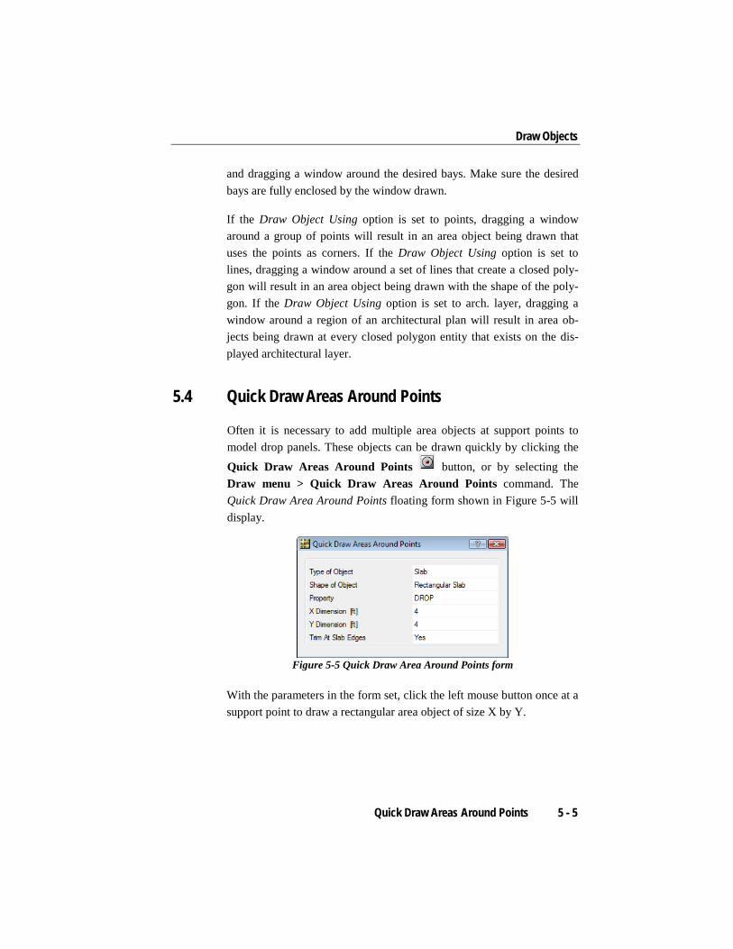
Often it is necessary to add multiple area objects at support points to model drop panels. These objects can be drawn quickly by clicking the Quick Draw Areas Around Points button, or by selecting the Draw menu > Quick Draw Areas Around Points command. The Quick Draw Area Around Points floating form shown in Figure 5-5 will display.
Figure 5-5 Quick Draw Area Around Points form
With the parameters in the form set, click the left mouse button once at a support point to draw a rectangular area object of size X by Y.
Quick Draw Areas Around Points 5 - 5
SAFE - Defining the Work Flow
5.5 Draw Design Strips
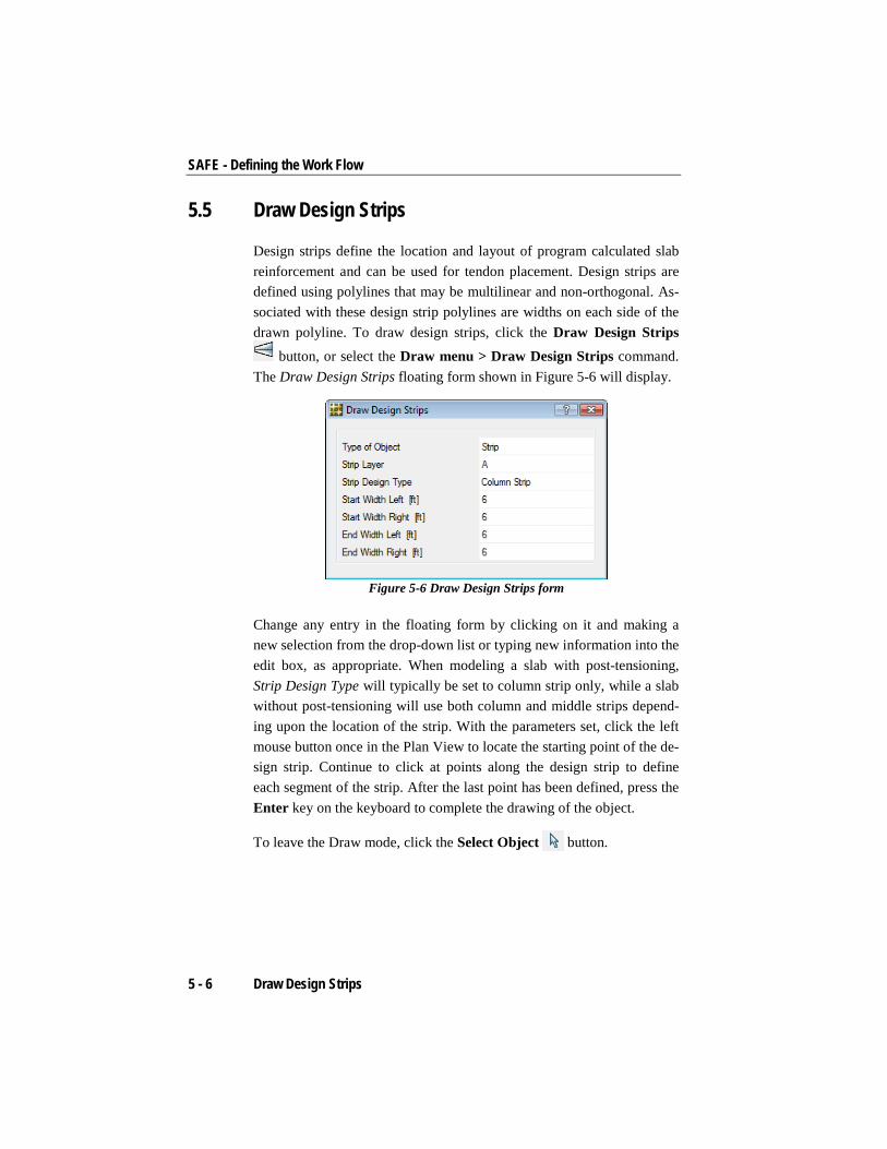
Design strips define the location and layout of program calculated slab reinforcement and can be used for tendon placement. Design strips are defined using polylines that may be multilinear and non-orthogonal. As-sociated with these design strip polylines are widths on each side of the drawn polyline. To draw design strips, click the Draw Design Strips
button, or select the Draw menu > Draw Design Strips command. The Draw Design Strips floating form shown in Figure 5-6 will display.
Figure 5-6 Draw Design Strips form
Change any entry in the floating form by clicking on it and making a new selection from the drop-down list or typing new information into the edit box, as appropriate. When modeling a slab with post-tensioning, Strip Design Type will typically be set to column strip only, while a slab without post-tensioning will use both column and middle strips depend-ing upon the location of the strip. With the parameters set, click the left mouse button once in the Plan View to locate the starting point of the de-sign strip. Continue to click at points along the design strip to define each segment of the strip. After the last point has been defined, press the Enter key on the keyboard to complete the drawing of the object.
To leave the Draw mode, click the Select Object button.
5 - 6 Draw Design Strips

Draw Objects
5.6 Draw Beams/Lines
To draw a beam/line object, activate the Plan View. Click the Draw Beams/Lines button, or select the Draw menu > Draw Beams/ Lines command. The Draw Beams/Lines floating form shown in Figure 5-7 will display.
Figure 5-7 Draw Beams/Lines form
Similar to slabs/areas, the floating form provides a Property drop-down list of the previously defined properties (see Chapter 4) that can be as-signed to the beam. To change an entry on the form, click on it and make a new selection from the drop-down list or type new information into the edit box, as appropriate.
With the parameters in the floating form set, click the left mouse button once anywhere in the Plan View to start drawing the beam/line. Move the cursor to the end point of the beam/line, and left click to complete the drawing of the beam/line. Moving the cursor to the next end point and left clicking will draw another segment. To start a new beam/line that is independent of the previous one, right click to discontinue the previous beam/line, then left click at the starting point of the new beam/line. To leave the Draw mode, click the Draw menu > Select Ob-ject command, or the Select Object button.
5.7 Quick Draw Beams/Lines
Beams/lines can be drawn quickly on the grid or between points by clicking the Quick Draw Beams/Lines button or the Draw menu >
Draw Beams/Lines 5 - 7

SAFE - Defining the Work Flow
Quick Draw Beams/Lines command. The Quick Draw Beams/Lines floating form similar to that shown in Figure 5-7 will display.
With the Draw Object Using option set to grids, change any other entry in the floating form by clicking on it and making a new selection from the drop-down list or typing new information into the edit box, as appro-priate. With the parameters in the floating form set, left click once in the Plan View on a grid line to place a beam/line object.
Alternatively, beams/lines on multiple grid lines can be generated by holding the left mouse button down and dragging a window around the desired grid lines or points. Make sure the desired grid lines and points are fully enclosed by the window drawn.
If the Draw Object Using option is set to points, dragging a window around a group of points will result in beam/line objects being drawn that create a closed polygon using the points as corners.
If the Draw Object Using option is set to arch. layer, dragging a window around a region of an architectural plan will result in beam/line objects being drawn at every line entity that exists on the displayed architectural layer.
To leave the Draw mode, click the Select Object button.
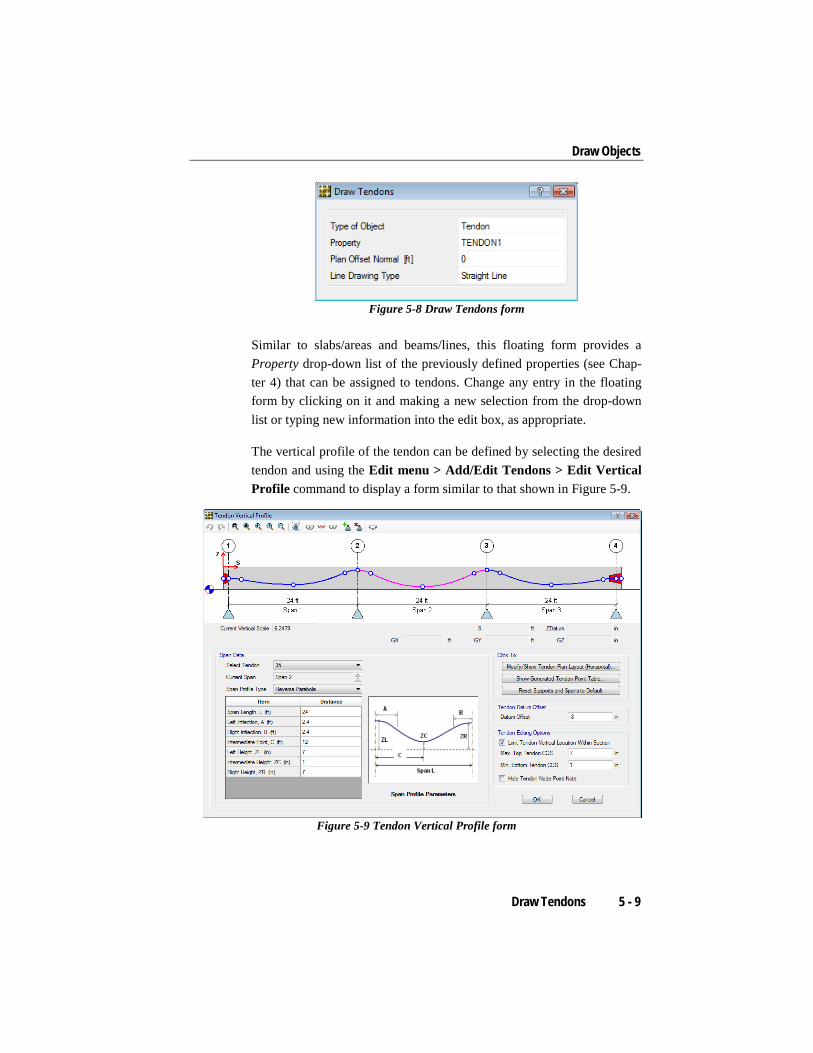
5.8 Draw Tendons
Tendons are used to input post-tensioning forces into the model. To draw a tendon, activate the Plan View. Click the Draw menu > Draw Ten-dons command, or the Draw Tendons button. The Draw Tendons floating form shown in Figure 5-8 will display.
5 - 8 Draw Tendons
Draw Objects
Figure 5-8 Draw Tendons form
Similar to slabs/areas and beams/lines, this floating form provides a Property drop-down list of the previously defined properties (see Chap-ter 4) that can be assigned to tendons. Change any entry in the floating form by clicking on it and making a new selection from the drop-down list or typing new information into the edit box, as appropriate.
The vertical profile of the tendon can be defined by selecting the desired tendon and using the Edit menu > Add/Edit Tendons > Edit Vertical Profile command to display a form similar to that shown in Figure 5-9.
Figure 5-9 Tendon Vertical Profile form
Draw Tendons 5 - 9

SAFE - Defining the Work Flow
The Tendon Vertical Profile form can be used to define the profile type and the vertical profile. A detailed description of the post-tensioning de-sign methodology is described in the Post-Tensioning Concrete Design manual.
5.9 Draw Columns
To draw a column object, click the Draw Columns button or use the Draw menu > Draw Columns command. The Draw Columns form shown in Figure 5-10 will display.
Figure 5-10 Draw Columns form
The form provides Property Below and Property Above drop-down lists of the previously defined properties (see Chapter 4) that can be assigned to the column. The corresponding heights of the column also are speci-fied on this form. Review the definitions and drawing controls (Plan Off-set X, Plan Offset Y, Angle, Cardinal Point) shown in the form before drawing the column. Change any entry in the form by clicking on it and making a new selection from the drop-down list or typing new infor-mation into the edit box, as appropriate.
With the parameters in the Draw Columns form set, left click anywhere to locate the column object. An outline of the column shape will appear in plan views and lines will be shown in 3-D views. Continue to place other columns by left clicking.
5 - 10 Draw Columns
Draw Objects
If a mistake is made while drawing, click the Select Object button to change from Draw mode to Select mode. Next click the Edit menu > Undo Column Object Add command. After all column objects have been drawn, click the Draw menu > Select Object command to leave the Draw mode.
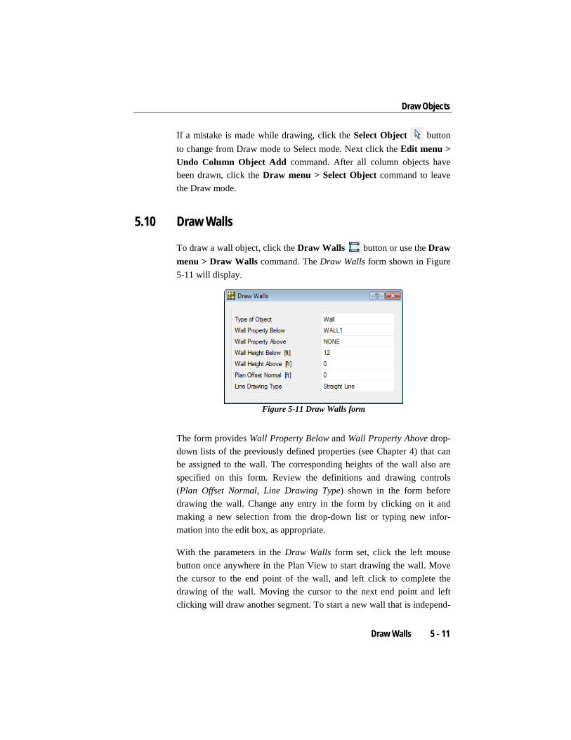
5.10 Draw Walls
To draw a wall object, click the Draw Walls button or use the Draw menu > Draw Walls command. The Draw Walls form shown in Figure 5-11 will display.
Figure 5-11 Draw Walls form
The form provides Wall Property Below and Wall Property Above drop-down lists of the previously defined properties (see Chapter 4) that can be assigned to the wall. The corresponding heights of the wall also are specified on this form. Review the definitions and drawing controls (Plan Offset Normal, Line Drawing Type) shown in the form before drawing the wall. Change any entry in the form by clicking on it and making a new selection from the drop-down list or typing new infor-mation into the edit box, as appropriate.
With the parameters in the Draw Walls form set, click the left mouse button once anywhere in the Plan View to start drawing the wall. Move the cursor to the end point of the wall, and left click to complete the drawing of the wall. Moving the cursor to the next end point and left clicking will draw another segment. To start a new wall that is independ-
Draw Walls 5 - 11

SAFE - Defining the Work Flow
ent of the previous one, right click to discontinue the previous wall, then left click at the starting point of the new wall.
If a mistake is made while drawing, click the Select Object button to change from Draw mode to Select mode. Next click the Edit menu > Undo Wall Add command. After all wall objects have been drawn, click the Draw menu > Select Object command to leave the Draw mode.
5.11 Draw Dimension Lines
Dimension lines help with the construction and verification of model ge-ometry. Dimension lines may be added to the Plan View by selecting the Draw menu > Draw Dimension Lines command or clicking the Draw Dimension Lines button. Left click once to locate the first extension line and click again to mark the location of the second extension line. Move the mouse to show the orientation and position of the extension and dimension lines; click at the desired location. If the extension lines were located initially by snapping to points or other objects, the dimen-sion lines will remain attached to those objects if the objects move. Di-mension lines are saved with the model.
5.12 Draw Slab Rebar
Slab rebar objects define the location and layout of user-defined slab re-inforcement and are defined using polylines that may be multilinear. As-sociated with these slab rebar object polylines are widths on each side of the drawn polyline. The slab rebar object is typically used to compare user specified slab reinforcing against program calculated reinforcing and to specify reinforcing for nonlinear cracking analyses.
To draw a slab rebar object, click the Draw Slab Rebar button or use the Draw menu > Draw Slab Rebar command. The Draw Slab Re-bar Object form shown in Figure 5-12 will display.
5 - 12 Draw Dimension Lines

Draw Objects
Figure 5-12 Draw Slab Rebar Object form
The form provides Rebar Size and Rebar Material drop-down lists of the previously defined properties (see Chapter 4) that can be assigned to the rebar object. The corresponding widths of the slab rebar object, as well as the vertical offset (top & bottom rebar) also are specified on this form. Depending upon the specification type, review either the total number of bars or the maximum bar spacing before drawing the slab rebar object. Change any entry in the form by clicking on it and making a new selec-tion from the drop-down list or typing new information into the edit box, as appropriate.
With the parameters in the Draw Slab Rebar Object form set, click the left mouse button once anywhere in the Plan View to start drawing the slab rebar object. Move the cursor to the end point of the slab rebar, and left click to complete the drawing of the slab rebar object. Moving the cursor to the next end point and left clicking will draw another segment. To start a new slab rebar object that is independent of the previous one, right click to discontinue the previous slab rebar object, then left click at the starting point of the new rebar object.
If a mistake is made while drawing, click the Select Object button to change from Draw mode to Select mode. Next click the Edit menu > Undo Slab Rebar Add command. After all slab rebar objects have been drawn, click the Draw menu > Select Object command to leave the Draw mode.
Draw Slab Rebar 5 - 13
Chapter 6 Select Objects
This chapter describes the options available for making selections in SAFE. Selections are used to identify existing objects to which the next operation will apply. It is necessary to first select objects in order to assign properties to objects. Selections can be made graphically or by referencing various properties of the objects. Selection operations are cumulative, i.e., each selection operation adds objects to the current set of selected objects and each deselection operation removes objects from the set.
Selected objects are shown graphically in the display windows with dashed lines. The number of selected objects of each type is shown in the status bar. It is always a good idea to check the status bar when perform-ing selection operations.
6.1 Selection by Graphical Methods
To enable the basic select mode, click the Select Object button on the toolbar, or click the Select menu > Select > Pointer/Window com-mand. SAFE has three basic methods of selecting objects in this mode:
Selection by Graphical Methods 6 - 1

SAFE – Defining the Work Flow
Left click: Click the left mouse button when the pointer is on an ob-ject to select it. If there are multiple objects, one on top of the other, hold down the Shift key on the keyboard and left click on the objects. The Selection List form similar to that shown in Figure 6-1 will dis-play and identify the objects that exist at that location. Select the de-sired object by moving the mouse pointer over it in the form and left clicking on it.
Figure 6-1 Selection List form
Enclosing Window (left to right): Draw a window around objects to select them by positioning the mouse pointer to the left and beyond the limits of the objects. Press and hold down the left mouse button and drag the mouse to a position to the right of the objects. Release the left mouse button to complete the selection.
As the mouse is dragged, a "rubber band window" will display. The rubber band window is a dashed rectangle that changes shape as the mouse is moved. Any visible object that is completely inside the rub-ber band window when the left mouse button is released is selected.
Intersecting Window (right to left): Position the mouse pointer to the right and beyond the limits of the objects to be selected. Press and hold down the left mouse button and drag the mouse to a position to the left of the objects. Release the left mouse button to complete the selection. Any visible object that is fully or partially enclosed in the window will be selected.
6 - 2 Selection by Graphical Methods

Select Objects
In addition to the default pointer/window selection mode, three other graphical selection options are available:
Poly: To select one or more objects by enclosing them within a poly-gon, click the Select menu > Select > Poly command. Position the mouse pointer beyond the limits of the objects to be selected. Click the left button on the mouse to indicate the first point of the polygon. Move the mouse pointer to the next point of the polygon and click again. As the mouse is moved, a “rubber band polygon” will display. After all points of the polygon have been input, complete the selection command by pressing the Enter key on the keyboard. Any visible ob-jects that are completely inside the rubber band polygon are selected.
Intersecting Poly: To select one or more objects crossed by a poly-gon, click the Select menu > Select > Intersecting Poly command. Draw the polygon in the same manner as the previous command. Any visible objects fully enclosed within or in contact with the rubber band polygon are selected.
Intersecting Line: To select one or more objects by drawing a line through them, click the Select menu > Select > Intersecting Line command or the Select using Intersecting Line button. Position the mouse pointer to one side of the objects to be selected. Click the left button on the mouse to indicate the beginning of the line. Move the mouse pointer to the end of the line segment and click again. As the mouse is moved, a “rubber band line” will display. The intersect-ing line may consist of multiple segments, and after all of the line segments have been input, complete the selection by pressing the En-ter key on the keyboard. Any visible object that is intersected (crossed) by the rubber band line segments is selected.
After using any of the preceding graphical selection methods, SAFE de-faults to the pointer/window selection mode. Thus, the menu commands or buttons must be used each time to access the select using Poly, Inter-secting Poly, or Intersecting Line methods.
Selection by Graphical Methods 6 - 3

SAFE – Defining the Work Flow
6.2 Selection by Features
Table 6-1 identifies the selection submenu commands and related ac-tions, accessed using the Select menu commands.
TABLE 6-1 Select Submenu Commands
Command / Button Action
Select > Properties > Material Properties
Select one or more material properties from the Select Mate-rials form, and all objects that have been assigned those materials will be selected.
Select > Properties > Slab Properties
Select one or more slab property names from the Select Slab Properties form, and all slab objects that have been assigned those slab properties will be selected.
Select > Properties > Slab Rebar Properties
Select one or more slab rebar property names from the Se-lect Slab Rebar Property form, and all slab rebar objects that were drawn with those rebar properties will be selected.
Select > Properties > Beam Properties
Select one or more beam property names from the Select Beam Properties form, and all beam objects that have been assigned those beam properties will be selected.
Select > Properties > Tendon Properties
Select one or more tendon property names from the Select Tendon Properties form, and all tendon objects that have been assigned those tendon properties will be selected.
Select > Properties > Column Properties
Select one or more column property names from the Select Column Properties form, and all the column objects that have been assigned those column properties will be selected.
Select > Properties > Wall Properties
Select one or more wall property names from the Select Wall Properties form, and all the wall objects that have been as-signed those wall properties will be selected.
Select > Properties > Soil Subgrade Properties
Select one or more soil subgrade property names from the Select Soil Subgrade Properties form, and all the slab objects that have those soil subgrade properties assigned to them will be selected.
Select > Properties > Point Spring Properties
Select one or more point spring property names from the Select Point Spring Properties form, and all the point objects that have those point spring properties assigned to them will be selected.
Select > Properties > Line Spring Properties
Select one or more line spring property names from the Se-lect Line Spring Properties form, and all the line objects that have those line spring properties assigned to them will be selected.
6 - 4 Selection by Features

Select Objects
TABLE 6-1 Select Submenu Commands
Command / Button Action
Select > Properties > Design Strip Layers
Select one or more strip layers from the Select Design Strip Layers form, and all the strips on those layers will be select-ed.
Select > Groups Select from the Select Groups form, the names of any collec-tions of objects that have been defined as groups, and those groups will be selected.
Select > Labels Select a label(s) from the Select by Labels form and the objects that have been assigned those labels will be select-ed.
Select > All
Selects all objects in the model, both visible and invisible objects. Be careful using this command. The Select All button also can be used to execute this command.
6.3 Deselect
Objects can be deselected one at a time by left clicking on the selected objects. Alternatively, use the Select menu > Deselect command and its submenus for quicker and more specific deselection actions. This com-mand accesses submenu items similar to those described in the previous two sections, except that executing the Select menu > Deselect com-mand and an associated submenu item deselects rather than selects ob-jects. As an example of the advantage of this option, assume that all ob-jects in a model need to be selected except for those with a particular beam property. This can be accomplished quickly and easily by first us-ing the Select menu > Select > All command and then using the Select menu > Deselect > Properties > Beam Properties command.
6.4 Invert Selection
Any objects not currently selected may be selected by using the Select menu > Invert Selection command, which simultaneously results in all currently selected objects being deselected. This command is helpful with a large model where only a few items should not be selected; select those objects first, and then use the Invert Selection command.
Deselect 6 - 5

SAFE – Defining the Work Flow
6.5 Get Previous Selection
The Select menu > Get Previous Selection command reselects the pre-viously selected objects. For example, assume that some area objects were selected by clicking on them and slab properties were assigned to them. Use the Get Previous Selection command or the Get Previous Selection button to reselect the area objects and assign something else to them, such as surface loads.
6.6 Clear Selection The Select menu > Clear Selection command and its associated Clear Selection button will deselect all currently selected objects. This is an all or nothing command and cannot be used to selectively clear a por-tion of a selection.
6 - 6 Get Previous Selection

Chapter 7 Assign Properties to the Model
This chapter describes how to assign or change the properties of struc-tural objects in the model. Note that properties and supports can be as-signed when the object is being drawn, as described in Chapter 5.
In creating a model, slabs/areas, beams/lines, tendons, columns, walls, and point objects are drawn. To enable analysis and design, these objects must have properties assigned. The definition of properties is explained in Chapter 4. The assignments that can be made to an object depend on the type of object. Table 7-1 identifies the assignments that can be made using the Assign menu commands, depending on the type of object.
TABLE 7-1 Available Assignments to Objects
Object Assignment Option Name of Form(s)
Points Support Data > Point Restraints Point Restraints
Support Data > Point Springs Point Spring Properties / Point Spring Property Data
Beams Beam Data > Properties Beam Properties/Beam Property Data Beam Data > Property Modifiers Property/Stiffness Modification Factors Beam Data > End Releases Assign Beam End Releases Beam Data > Insertion Point Insertion Point
Assign Properties to the Model 7 - 1

SAFE – Defining the Work Flow
TABLE 7-1 Available Assignments to Objects
Object Assignment Option Name of Form(s) Support Data > Line Springs Line Spring Properties/Line Spring
Property Data
Tendons Tendon Properties Tendon Property Assign
Slabs Slab Data > Properties Slab Properties/Slab Property Data
Slab Data > Property Modifiers Property/Stiffness Modification Factors
Slab Data > Vertical Offset Slab Offset Slab Data > Local Axis Slab Local Axis Slab Data > Edge Releases Slab Edge Releases Slab Data > Line Releases Slab Line Releases Slab Data > Rib Locations Slab Rib Location Slab Data > Opening Slab Opening Support Data > Soil Properties Soil Subgrade Properties/Soil Subgrade
Property Data Columns/ Braces
Column/Brace Data > Properties Column Properties/Column Property Data
Column/Brace Data > Property Modifiers
Property/Stiffness Modification Factors
Column/Brace Data > Local Axis Column Local Axis
Column/Brace Data > End Releases Assign Column End Releases Column/Brace Data > Insertion Point Insertion Point Walls/ Ramps
Wall/Ramp Data > Properties Wall Properties/Wall Property Data
Wall/Ramp Data > Property Modifiers Property/Stiffness Modification Factors
Wall/Ramp Data > Opening (Walls Only)
Wall Opening
Wall/Ramp Data > Normal Offset Wall/Ramp Offset
Supports Support Data > Soil Properties Soil Subgrade Properties/Soil Subgrade Property Data
Support Data > Line Springs Line Spring Properties/Line Spring Proper-ty Data
Support Data > Point Restraints Point Restraints
7 - 2 Assign Properties to the Model

Assign Properties to the Model
TABLE 7-1 Available Assignments to Objects
Object Assignment Option Name of Form(s)
Support Data > Point Springs Point Spring Properties/Point Spring Prop-erty Data
Releases, point restraints, insertion points, rib locations, property modi-fiers, local axes, and openings are assigned directly to objects. These properties can be changed only by making another assignment of that same property to the object. They are not named entities and do not exist independently from the objects.
The assignments made to point, beam, column, tendon, slab, and wall objects can be viewed by clicking the right mouse button while the mouse pointer is on an object. The appropriate Point Object Information form, Beam-Type Line Object Information form, Tendon Object Infor-mation form, Slab-Type Area Object Information form, and so on, will display.
An object must be selected before executing the desired assignment command (for example, a beam object must be selected before using the Assign menu > Beam Data commands). As explained in Chapter 6, us-ing the Shift key and left clicking on a location in the model can simpli-fy the process of selecting objects when multiple objects are present at the same location.
As shown in Table 7-1, the availability of commands depends on the type of object selected. The input forms include object assignment-specific input fields that enable refinement of the assignment. Modifica-tions to the assignments can be made by accessing the input forms using the appropriate Assign menu commands. Context sensitive help explain-ing the various forms is available by pressing the F1 function key on the keyboard while a form is displayed.
Loads also can be assigned to slabs, beams, tendons, and points. These commands are described in Chapter 8.
Assign Properties to the Model 7 - 3
Chapter 8 Load the Model
This chapter describes defining and assigning loads to a model. Loads, including dead, live, earthquake, snow, temperature, and the like, are de-fined as load patterns that are assigned to various structural objects in the model.
Note that SAFE automatically creates a load case for each load pattern, and these load cases are assembled into design load combinations in ac-cordance with the specified building code. The design code can be se-lected using the Design menu > Design Preferences command.
8.1 Define Load Patterns
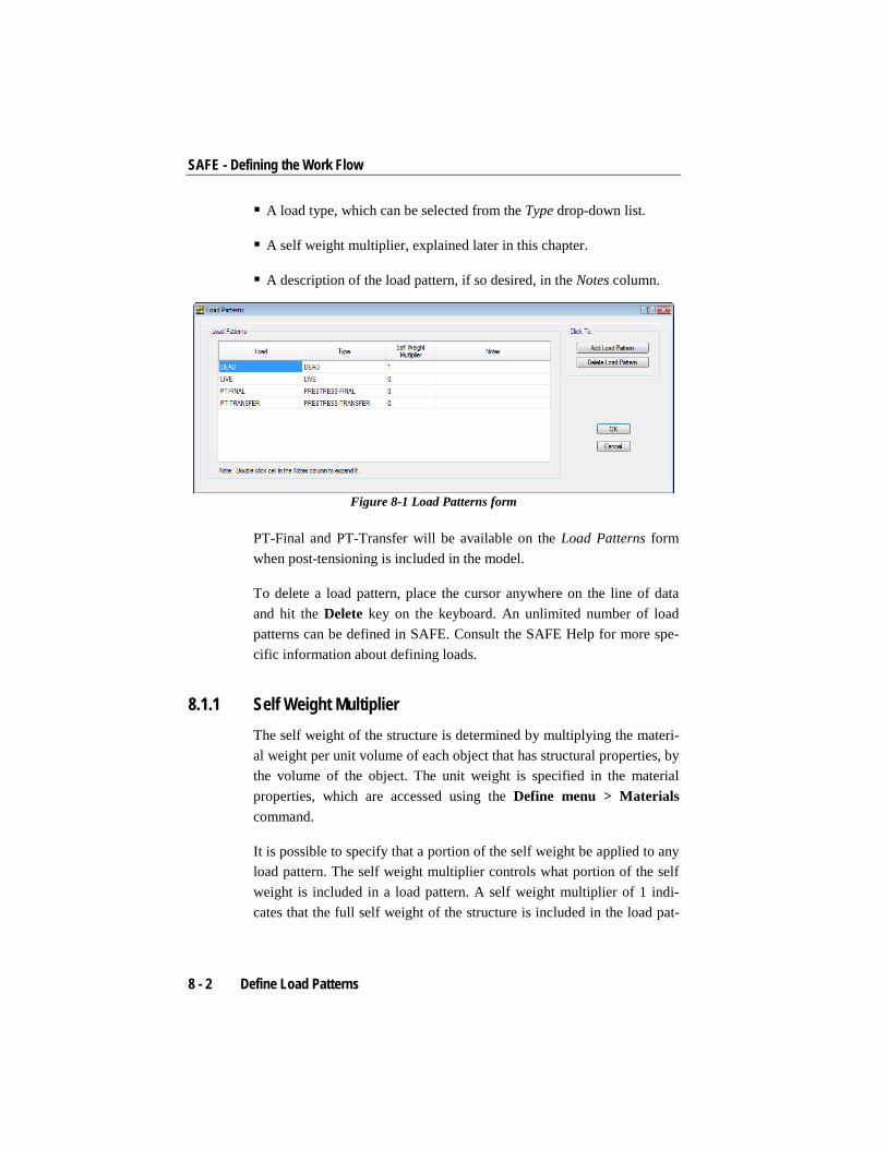
Click the Define menu > Load Patterns command or double click on a load pattern name found under the Load Patterns item in the Model Ex-plorer window to display the Load Patterns form shown in Figure 8-1.
Use the form to specify the following information:
The name of the load pattern. SAFE does not allow use of duplicate names.
Define Load Patterns 8 - 1
SAFE - Defining the Work Flow
A load type, which can be selected from the Type drop-down list.
A self weight multiplier, explained later in this chapter.
A description of the load pattern, if so desired, in the Notes column.
Figure 8-1 Load Patterns form
PT-Final and PT-Transfer will be available on the Load Patterns form when post-tensioning is included in the model.
To delete a load pattern, place the cursor anywhere on the line of data and hit the Delete key on the keyboard. An unlimited number of load patterns can be defined in SAFE. Consult the SAFE Help for more spe-cific information about defining loads.
8.1.1 Self Weight Multiplier The self weight of the structure is determined by multiplying the materi-al weight per unit volume of each object that has structural properties, by the volume of the object. The unit weight is specified in the material properties, which are accessed using the Define menu > Materials command.
It is possible to specify that a portion of the self weight be applied to any load pattern. The self weight multiplier controls what portion of the self weight is included in a load pattern. A self weight multiplier of 1 indi-cates that the full self weight of the structure is included in the load pat-
8 - 2 Define Load Patterns

Load the Model
tern. A self weight multiplier of 0.5 indicates that half of the self weight of the structure is included in the load pattern.
Normally a self weight multiplier of 1 should be specified in one load pattern only, usually the dead load pattern. All other static load patterns then have self weight multipliers of zero.
Important Note: If a self weight multiplier of 1 is defined for two dif-ferent load patterns and they are combined in a load case or combination, the results for the load case or combination are based on an analysis where double the self weight of the structure is applied.
8.1.2 Auto Live Load Patterning Auto live load patterning allows a live load pattern to be automatically applied to the slab in critical patterns to increase the negative and posi-tive moments in slab panels and columns. With auto live load patterning, the associated loads applied to the load pattern are automatically divided up into smaller “single panel” load patterns based on the panels created by the layout of the grids. SAFE then uses the Range Add load combina-tion feature to combine the results from each of these “single panel” loads automatically.
8.2 Assign Loads
Static loads can be assigned to point, beam, tendon, and slab objects. The objects must first be selected before a load can be assigned. Chapter 6 describes the options for selecting structural objects.
After the objects have been selected, click the Assign menu command to access the applicable submenu and assignment options. Note that the type of object selected determines which assignment can be made. For example, if a slab object is selected, the Assign menu > Load Data > Surface Loads or Assign menu > Load Data > Slab Temperature Loads commands will be available, while a point selection will allow use of either the Assign menu > Load Data > Point Loads or Load Da-ta > Point Displacements commands. If a tendon object is selected, the
Assign Loads 8 - 3

SAFE - Defining the Work Flow
Assign menu > Load Data > Tendon Loads or Assign menu > Load Data > Tendon Losses commands will be active. If only point objects (e.g., column supports) and beam objects are selected, the Assign menu > Load Data > Surface Loads command will not be active.
After clicking the Assign menu and the submenu command applicable to the type of object, a form will display. Table 8-1 identifies the forms generated when the various Assign menu > Load Data commands are used. Consult the SAFE Help for more specific information about as-signing loads.
TABLE 8-1 Load Commands on the Assign Menu
Command Name of Input Form
Load Data > Surface Loads Surface Loads
Load Data > Slab Temperature Loads Slab Temperature Loads
Load Data > Point Loads on Lines Point Loads on Lines
Load Data > Distributed Loads on Lines Distributed Loads on Lines
Load Data > Point Loads Point Loads
Load Data > Point Displacements Point Displacement Loads
Load Data > Tendon Loads Tendon Load
Load Data > Tendon Losses Tendon Loss Options
Although the forms vary depending on the command used, each form has a drop-down list that allows selection of the load pattern to which the loads are to be assigned. The forms also include other object assignment-specific input fields that enable refinement of the load assignment. Con-text-sensitive help is available for each form by pressing the F1 function key on the keyboard when the form is displayed.
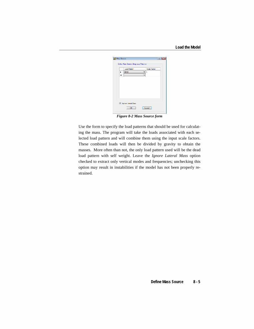
8.3 Define Mass Source
Before performing a modal (dynamic) analysis, the mass source for the model must be defined. Click the Define menu > Mass Source com-mand to display the Mass Source form shown in Figure 8-2.
8 - 4 Define Mass Source
Load the Model
Figure 8-2 Mass Source form
Use the form to specify the load patterns that should be used for calculat-ing the mass. The program will take the loads associated with each se-lected load pattern and will combine them using the input scale factors. These combined loads will then be divided by gravity to obtain the masses. More often than not, the only load pattern used will be the dead load pattern with self weight. Leave the Ignore Lateral Mass option checked to extract only vertical modes and frequencies; unchecking this option may result in instabilities if the model has not been properly re-strained.
Define Mass Source 8 - 5

Chapter 9 Define Load Cases
A load case defines how loads are to be applied to the structure, and how the structural response is to be calculated. Analyses are classified in the broad sense as either linear, nonlinear, modal, or hyperstatic, depending on how the model responds to the loading. The results of linear analyses may be superposed, i.e., added together after analysis. The results of nonlinear analyses normally should not be superposed. Instead, all loads acting together on the structure should be combined directly within the nonlinear load case. Any number of named load cases may be defined.
9.1 Review/Create Load Cases
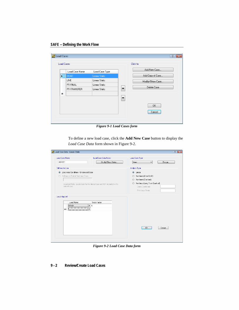
After all geometry and loading input has been specified for a model, re-view, modify, or add load cases using the Define menu > Load Cases command. The Load Cases form shown in Figure 9-1 will display. High-light a load case (SAFE automatically generates a load case for each load pattern defined) and click the Modify/Show Case button to review or al-ter the load case definition. Click the Delete Case button to delete a highlighted load case.
Review/Create Load Cases 9 - 1
SAFE – Defining the Work Flow
Figure 9-1 Load Cases form
To define a new load case, click the Add New Case button to display the Load Case Data form shown in Figure 9-2.
Figure 9-2 Load Case Data form
9 - 2 Review/Create Load Cases

Define Load Cases
Use that form to specify the following information:
The name of the load case. SAFE does not allow use of duplicate names.
Notes about the specific load case.
A load case type, which can be selected from the Load Case Type drop-down list. The default setting of static is the most common choice, but modal and hyperstatic also are available. A static case con-siders loads defined in a load pattern, a modal case carries out a fre-quency analysis, and a hyperstatic case applies loads to the structure in an unsupported state, from a chosen static case.
The analysis type: linear or nonlinear (uplift, cracked, or long term cracked). If nonlinear (long term cracked) has been selected, creep co-efficient and shrinkage strain values should be specified to effectively compute long term deflections.
The initial stiffness to use. The load case may start with zero initial conditions or with a stiffness determined from a nonlinear load case.
The loads to be applied, defined by the load name and a scale factor.
Click the OK button to accept the changes made on the form, or click Cancel to cancel the changes and return to the Load Cases form.
Review/Create Load Cases 9 - 3
Chapter 10 View and Edit the Model Geometry
SAFE provides many ways to view a model, as well as a wide selection of tools to edit and revise the model data. This chapter provides an over-view of some of the commands available to make editing and reviewing a model easy.
10.1 Changing Views
SAFE always starts with a Plan View as the default view. Clicking the Options menu > Windows command and selecting one of the subcom-mands allows the number of display windows to be changed. Table 10-1 identifies a few View menu commands that may be used to change what is displayed in the active window. For the commands listed, a window should be made active (click anywhere in the window) before using the commands.
TABLE 10-1 View Menu Commands in SAFE
Command/Button Action Immediate/ Form/ Toggle
Changing Views 10 - 1
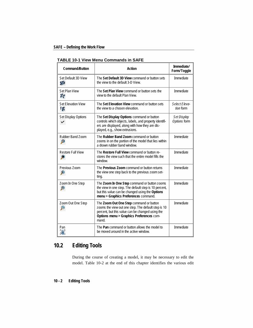
SAFE – Defining the Work Flow
TABLE 10-1 View Menu Commands in SAFE
Command/Button Action Immediate/ Form/ Toggle
Set Default 3D View
The Set Default 3D View command or button sets the view to the default 3-D View.
Immediate
Set Plan View
The Set Plan View command or button sets the view to the default Plan View.
Immediate
Set Elevation View
The Set Elevation View command or button sets the view to a chosen elevation.
Select Eleva-tion form
Set Display Options
The Set Display Options command or button controls which objects, labels, and property identifi-ers are displayed, along with how they are dis-played, e.g., show extrusions.
Set Display Options form
Rubber Band Zoom
The Rubber Band Zoom command or button zooms in on the portion of the model that lies within a drawn rubber band window.
Immediate
Restore Full View
The Restore Full View command or button re-stores the view such that the entire model fills the window.
Immediate
Previous Zoom
The Previous Zoom command or button returns the view one step back to the previous zoom set-ting.
Immediate
Zoom In One Step
The Zoom In One Step command or button zooms the view in one step. The default step is 10 percent, but this value can be changed using the Options menu > Graphics Preferences command.
Immediate
Zoom Out One Step
The Zoom Out One Step command or button zooms the view out one step. The default step is 10 percent, but this value can be changed using the Options menu > Graphics Preferences com-mand.
Immediate
Pan
The Pan command or button allows the model to be moved around in the active window.
Immediate
10.2 Editing Tools
During the course of creating a model, it may be necessary to edit the model. Table 10-2 at the end of this chapter identifies the various edit
10 - 2 Editing Tools

View and Edit the Model Geometry
commands available in SAFE, some of which are familiar Windows commands.
In most cases, first select the point, beam, column, tendon, design strip, wall, slab rebar, or slab object and then click the appropriate menu item or button. In some cases, the action will be immediate (for example, the Undo or Redo commands). In other cases, a form will display that al-lows specification of how the object is to be edited. For example, the Edit menu > Replicate command accesses the Replicate form, which al-lows replication of point, beam, column, tendon, design strip, wall, slab rebar, or slab objects in one of three ways. In other cases, the command is a toggle that, when enabled, will affect subsequent actions. Note that the type of commands and options available depends on the type of ob-ject being edited.
10.2.1 Interactive Database Editing Interactive database editing is a very powerful editing capability within SAFE that allows the model or a selection of the model to be edited di-rectly in SAFE or passed out to Microsoft Excel, edited, and read back into SAFE. Interactive database editing is accessed using the Edit menu > Interactive Database Editing command, which brings up the form shown in Figure 10-1.
Editing Tools 10 - 3

SAFE – Defining the Work Flow
Figure 10-1 Choose Tables for Interactive Editing form
That form displays a tree of the available tables for editing. The listed tables will depend on the objects, definitions, and assignments present in the model. Click on a table to select it for editing. Multiple tables can be marked for editing.
Upon clicking the OK button, a form similar to that shown in Figure 10-2 will display with the chosen tables and their associated data.
10 - 4 Editing Tools

View and Edit the Model Geometry
Figure 10-2 Interactive Database Editing form
The data can be edited directly in that form by clicking in a cell of the table and modifying the current value. It is possible to apply the changes to the model without closing the interactive editing form using the Ap-ply to Model button. When finished, click the Done button to exit inter-active editing.
Alternatively, the data can be taken out to Microsoft Excel using the To Excel button. This will open Microsoft Excel with a copy of the current-ly displayed table. Without closing the form in SAFE, changes should be made to the Excel file and when finished, click the From Excel button in the SAFE form. Note, it is not necessary to save the Excel file before reading it back into SAFE.
TABLE 10-2 Edit Menu Commands in SAFE
Command/Button Action Immediate/ Form/ Toggle
Undo and Redo
The Undo command or button deletes the last performed action. The Redo command or button restores the last step.
Immediate
Editing Tools 10 - 5

SAFE – Defining the Work Flow
TABLE 10-2 Edit Menu Commands in SAFE
Command/Button Action Immediate/ Form/ Toggle
Cut, Copy, and Paste Generally similar to the standard cut, copy, and paste Windows commands.
Immediate
Delete The Delete command deletes the selected objects and all of the associated assignments (loads, properties, supports, and the like).
Immediate
Grid Data > Add/Modify Grids
Allows coordinate systems to be modified or de-leted, or a new coordinate system to be defined.
Coordinate Systems form
Grid Data > Add Grid at Selected Points
Adds grid lines at the selected points in specified orientations.
Add Grid Lines at Selected Points form
Grid Data > Glue Points to Grids
Enables or disables gluing of points to grids such that the points lying on a grid line move if the grid line is moved.
Toggle
Grid Data > Lock On-Screen Grid System Edit
Enables or disables onscreen editing/movement of grid lines.
Toggle
Interactive Database Editing
Database editing can be done in the SAFE form or externally, in Microsoft Excel using this com-mand. Specific items can be selected before using the Interactive Database Editing command, thereby controlling the list of items to be edited.
Choose Tables for Interactive Editing form (see Fig. 10-1 and Fig. 10-2 )
Replicate Duplicates the selected objects to specified loca-tions using linear replication, radial replication, or replication about a mirror plane. Note that this command differs from the Copy command be-cause it also copies any assignments made to the line or area object.
Replicate form
Merge Points Merges points within the tolerance distance of the selected point. A tolerance distance is specified on the Merge Points form.
Merge Points form
Align Points/Lines/Edges Aligns selected points. Points can be aligned to an X-ordinate, Y-ordinate, or to the nearest selected line. When a point object is re-aligned, all objects attached to the point are reoriented or resized to account for the movement. The Align Points/Lines/Edges form can also trim line/tendon/strip objects that are too long, or ex-tend objects that are too short. NOTE: This is a sophisticated and complex command, and it is strongly suggested that the behavior be verified before using it on a large model.
Align Points/Lines/Edge
s form
10 - 6 Editing Tools
View and Edit the Model Geometry
TABLE 10-2 Edit Menu Commands in SAFE
Command/Button Action Immediate/ Form/ Toggle
Move Points/Lines/Areas Moves point objects in the model. When a point object is moved, all objects attached to the point are reoriented or resized to account for the movement.
Move Points/Lines/Area
s form
Edit Lines > Divide Lines Divides a line object into multiple line objects. Divide Lines form Edit Lines > Join Lines Joins two or more colinear line objects with com-
mon end points and the same type of property into a single line object.
Immediate
Edit Lines > Convert Beams to Slab Areas
Converts a beam line object to a slab area object with plan dimensions equal to the width and length of the beam and a thickness equal to the depth as defined by the assigned beam property. Any loads assigned to the beam will remain as a line load.
Immediate
Edit Lines > Modify/Show Line Type
Allows modification of the line type to be either straight or curved.
Line Object Type Options form
Edit Areas > Divide Are-as
Divides an area object into multiple area objects. Divide Selected Areas form
Edit Areas > Merge Are-as
Converts selected area objects that are touching or overlapping into a single area object. Only two objects can be merged at a time.
Immediate
Edit Areas > Expand/ Shrink Areas
Expands or shrinks an area object by a specified offset value.
Expand/Shrink Areas form
Edit Areas > Split Area Edges
Splits the selected area object edges into a speci-fied number of segments.
Split Area Edges form
Edit Areas > Remove Points from Areas
Removes the selected point from the selected area object resulting in a change to the area ob-ject shape, i.e., an area object defined by five points becomes an area object defined with four points. Not recommended for use on area objects with less than four points.
Immediate
Edit Areas > Chamfer Slab Corners
Allows chamfering of the selected slab corner using either beveled or rounded edges.
Chamfer Slab Corners form
Edit Areas > Modi-fy/Show Slab Edge Type
Allows modification of the slab edge to be either straight or curved.
Slab Area Object Edge Type Op-
tions form Edit Areas > Modi-fy/Show Wall Curve Type
Allows modification of the wall to be either straight or curved.
Wall Area Object Curve Type Op-
tions form
Editing Tools 10 - 7

SAFE – Defining the Work Flow
TABLE 10-2 Edit Menu Commands in SAFE
Command/Button Action Immediate/ Form/ Toggle
Add/Edit Tendons > Add Tendons in Strips
Where PT tendons are to be added to a particular strip, this command provides easy tendon as-signment for the selected strips.
Quick Tendon Layout form
Add/Edit Tendons > Add Tendon to Beams
Where PT tendons are to be added to a particular beam, this command provides easy tendon as-signment for the selected beams.
Immediate
Add/Edit Tendons > Edit Plan Layout (Horizontal)
Allows modification of the tendon to be either straight or curved in the horizontal plane.
Tendon Object Type Options form
Add/Edit Tendons > Edit Vertical Profile
Allows modification of the tendons vertical profile on a span by span basis.
Tendon Vertical Profile form
Add/Edit Tendons > Reset Supports and Spans to Default
Resets the tendon support points and span defini-tions to the program default if they have been modified using the vertical profile form.
Immediate
Add/Edit Tendons > Copy Vertical Profile
Copies the vertical profile of a tendon. This com-mand is only available when a single tendon is selected.
Immediate
Add/Edit Tendons > Paste Vertical Profile
Pastes the vertical profile copied from a tendon, to any number of selected tendons.
Immediate
Add/Edit Slab Rebar > Add Slab Rebar
Allows for placement of user-defined reinforce-ment – similar in functionality to the Draw menu > Draw Slab Rebar command.
Slab Rebar Object Data form
Add/Edit Slab Rebar > Edit Slab Rebar
Allows modification of the selected slab rebar object.
Slab Rebar Object Data form
Add/Edit Design Strips > Add Design Strips
Provides a quick method to define design strips along grids or based on structural supports.
Add Design Strips form
Add/Edit Design Strips > Edit Strip Widths
Allows the strip widths to be modified, either with user defined widths or automatic widening of strips by SAFE.
Edit Strip Widths form
With a form displayed, press the F1 function key on the keyboard to ac-cess context-sensitive help about the form.
10 - 8 Editing Tools

Chapter 11 Analysis and Design
After all geometry and loads have been input into the model, it is ready for analysis and design. This chapter provides an overview of the analy-sis and design process in SAFE.
11.1 Set the Mesh Options
Before running the analysis, set the meshing options using the Run menu > Automatic Slab Mesh Options command. The Automatic Slab Mesh Options form shown in Figure 11-1 will display.
Set the Mesh Options 11 - 1

SAFE – Defining the Work Flow
Figure 11-1 Automatic Slab Mesh Options form
Use the Automatic Slab Mesh Options form to specify the type and max-imum size of mesh to use. The rectangular mesh provides three methods. It can either create a mesh that is parallel and perpendicular to the long-est edge, the grid system, or the local axes of the area objects. During analysis, SAFE automatically meshes the model based on these parame-ters to create a finite element model. Generation of the mesh is influ-enced by the locations of slab objects, openings, beams and line springs, columns, walls, and point restraints and springs. To preview the element mesh before running the analysis and design, use the View menu > Set Display Options command. When the Set Display Options form dis-plays, check the Show Mesh check box under the Options category.
11.2 Design Process Design can be performed automatically as part of the analysis run if the Run menu > Run Analysis & Design command is used. SAFE designs both concrete slabs and beams, and checks punching shear. The type of design depends on the type of members used in the model (e.g., a beam design will be performed only if beam objects are included in the mod-el). Specific material properties and design data are input using the De-fine menu commands, and design code preferences are selected using the Design menu > Design Preferences command.
11 - 2 Design Process

Analysis and Design
The Design menu > Design Preferences command allows the desired design code to be selected, as well as defining the slab and beam rein-forcement covers, the post-tensioned allowable stress limits, and preferred reinforcement bar sizes.
Table 11-1 summarizes the commands on the Design menu used in the design process. User-defined load combinations can be specified in addi-tion to the automatic program generated load combinations that are spe-cific to the selected design code. Overwrites to strips, slabs, beams, and punching shear design also can be specified to further customize the de-sign process on an object-by-object basis.
TABLE 11-1 Design menu commands Command Action Form
Design Preferences
Allows input and control of all design parameters for mild reinforcement and post-tensioning.
Design Preferences
Design Combos Allows review of the load combinations. Allows specific combinations to be chosen for use in the design for strength and the various service conditions.
Design Load Combinations
Selection
Slab Design Overwrites > Strip Based
Allows for the review/editing (overwriting) of default (as determined by the program) strip based slab design parameters.
Strip Based Slab Design
Overwrites
Slab Design Overwrites > Finite Element Based
Allows for the review/editing (overwriting) of default (as determined by the program) finite element based slab design parameters.
Finite Element Based Slab Design
Overwrites
Beam Design Overwrites
Allows for the review/editing (overwriting) of default (as determined by the program) beam design parameters.
Beam Design Overwrites
Punching Check Overwrites
Allows for the review/editing (overwriting) of default (as determined by the program) punching shear design parameters.
Punching Shear Design Overwrites
11.3 Run Analysis and Design
To start the analysis and design, use the Run menu > Run Analysis & Design command or click the Run Analysis & Design button. In the lower left- hand corner of the screen, the status bar will display mes-
Run Analysis and Design 11 - 3
SAFE – Defining the Work Flow
sages indicating the status of the analysis. When the entire analysis pro-cess is complete, a deformed shape view of the model is automatically displayed, and the model is locked. The model is locked when the Lock/Unlock Model button shows the padlock in the closed, or locked position. Locking the model prevents changes to the model that would invalidate the analysis results.
Consult the SAFE Help topics and the CSI Analysis Reference manual for more information about analyzing models.
11.4 Locking and Unlocking the Model
After an analysis has been performed, SAFE automatically locks the model to prevent any changes that would invalidate the analysis results and subsequent design results. The model also can be locked at any time to prevent changes, or unlock it to permit changes using the Options menu > Lock/Unlock Model command or the Lock/Unlock Model button. SAFE will display a warning message that analysis results will be deleted if a model is unlocked following an analysis.
11 - 4 Locking and Unlocking the Model

Chapter 12 Reinforcement Detailing
After the analysis and design are complete, the reinforcement detailing can be run. This chapter provides an overview of the detailing process available for generating detailed drawings based on the analysis and de-sign results.
Note that the analysis and design must be complete before running the detailing. Re-running the detailing does not execute a re-analysis. If changes have been made to the model that will affect the design, it is necessary to re-run the analysis and design before re-running the detail-ing.
12.1 Detailing Process
SAFE detailing generates two basic forms of output:
Drawing component views of detailed objects, such as elevations, plans, sections, and tables
Drawing sheets containing an assemblage of component views
Detailing Process 12 - 1
SAFE – Defining the Work Flow
The reinforcement detailing is based on user-defined preferences. De-fault preferences are defined as a starting point, but should be reviewed and modified as necessary before running the detailing.
Detailing generates a default set of drawing component views and draw-ing sheets that can be modified, which automatically updates all related views and drawing sheets. The generated views can be edited to improve text readability and to add additional annotations, allowing complete control over the information contained on the drawing sheets, including drawing size, scale, layout, title block, and component views. Drawings can be printed directly from SAFE or exported for further manipulation in CAD applications.
The editing and modifications to the objects, views, and drawing sheets are retained to the extent practicable during the synchronization process even if the model is changed and analysis and design is repeated. This automatic synchronization also helps to apply modified options and preferences to existing detailing output.
12.2 Preferences
The detailing preferences specify various parameters such as the cur-tailment rules, dimensioning units, preferred bar sizes, min and max bar lengths, drawing sheet size and scale, line styles, and many other cus-tomizable parameters.
The detailing units, as well as other preferences, are set using the Detail-ing menu > Detailing Preferences command. This brings up the form shown in Figure 12-1. This form also allows the desired rebar set to be chosen, the bar mark style to be set, as well as various other units to be defined.
12 - 2 Preferences
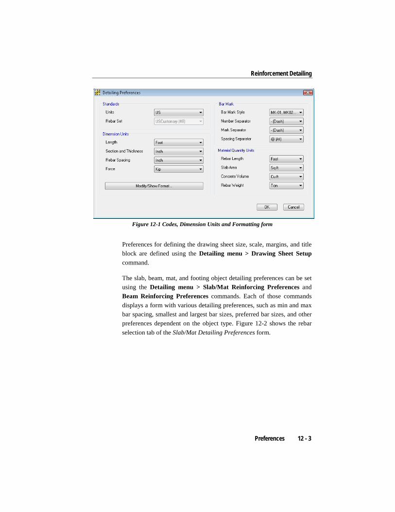
Reinforcement Detailing
Figure 12-1 Codes, Dimension Units and Formatting form
Preferences for defining the drawing sheet size, scale, margins, and title block are defined using the Detailing menu > Drawing Sheet Setup command.
The slab, beam, mat, and footing object detailing preferences can be set using the Detailing menu > Slab/Mat Reinforcing Preferences and Beam Reinforcing Preferences commands. Each of those commands displays a form with various detailing preferences, such as min and max bar spacing, smallest and largest bar sizes, preferred bar sizes, and other preferences dependent on the object type. Figure 12-2 shows the rebar selection tab of the Slab/Mat Detailing Preferences form.
Preferences 12 - 3

SAFE – Defining the Work Flow
Figure 12-2 Slab/Mat Detailing Preferences form
Each detailed object is comprised of lines, text, arrows, and colored fill. The line types, line colors, arrow styles, font type, font size, font color, and so forth, can all be customized for each object type. The default set-tings are typically adequate, but it may be desirable to modify them. The Detailing menu > Drawing Format Properties command displays the Drawing Format Properties form. This form allows for setting the styles and colors of all the various types of formatting items used in the detail-ing.
The detailing preferences are saved with the model and can therefore be reused when the detailing is rerun or when a new model is initialized from an existing model that already has the detailing preferences set.
12 - 4 Preferences
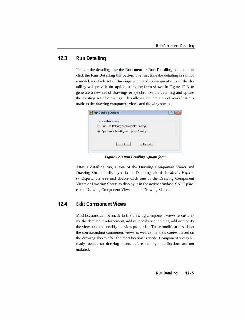
Reinforcement Detailing
12.3 Run Detailing
To start the detailing, use the Run menu > Run Detailing command or click the Run Detailing button. The first time the detailing is run for a model, a default set of drawings is created. Subsequent runs of the de-tailing will provide the option, using the form shown in Figure 12-3, to generate a new set of drawings or synchronize the detailing and update the existing set of drawings. This allows for retention of modifications made to the drawing component views and drawing sheets.
Figure 12-3 Run Detailing Options form
After a detailing run, a tree of the Drawing Component Views and Drawing Sheets is displayed in the Detailing tab of the Model Explor-er. Expand the tree and double click one of the Drawing Component Views or Drawing Sheets to display it in the active window. SAFE plac-es the Drawing Component Views on the Drawing Sheets.
12.4 Edit Component Views
Modifications can be made to the drawing component views to custom-ize the detailed reinforcement, add or modify section cuts, add or modify the view text, and modify the view properties. These modifications affect the corresponding component views as well as the view copies placed on the drawing sheets after the modification is made. Component views al-ready located on drawing sheets before making modifications are not updated.
Run Detailing 12 - 5

SAFE – Defining the Work Flow
The detailed reinforcement can be modified using the Detailing menu > Edit Reinforcement commands. Depending on the objects present in the model, separate commands will be available for slabs/mats and beams. The reinforcement editing allows the rebar sizes, spacing, lengths, and curtailment location to be modified. Note, it is strongly recommended that these changes be made with caution to ensure that the reinforcement specified adheres to code requirements, as specified by default.
Defined section cuts generate additional drawing component views for the main structural objects. Default section cuts are generated when the detailing is first run. These can be modified or deleted, or additional sec-tion cuts can be defined, using the Detailing menu > Add/Modify Sec-tions commands. Depending on the objects present in the model, sepa-rate commands will be available for slabs/mats and beams.
The text on a drawing component view can be fully customized, includ-ing editing of the program generated text, as well as adding additional text, notes, and dimension lines. To modify the text on a specific draw-ing component view, right click on the component view in the display or on the detailing tree of the Model Explorer and choose the Edit View Text command. A form is opened showing the view and contains a wide selection of tools for zooming the view and making the necessary modi-fications.
Each drawing component view also has its own properties that specify its name, scale, as well as the text and line sizes. These preferences can be modified by right clicking the component view in either the display or on the detailing tree of the Model Explorer and choosing the Edit View Properties command.
12.5 Create and Manage Drawing Sheets
The drawing sheets are a collection of scaled drawing component views, ready for direct printing or export to other file formats. SAFE automati-cally creates a set of default drawings with appropriate views. Several tools are available to create new drawing sheets and to modify and man-age exiting sheets.
12 - 6 Create and Manage Drawing Sheets
Reinforcement Detailing
The list of drawing sheets can be modified using the Detailing menu > Edit Drawing Sheets List command. Additional drawing sheets also may be added by right clicking on the Drawing Sheets node of the detail-ing tree in the Model Explorer window, and choosing the Add Blank Drawing Sheet command. Individual drawings can be deleted by right clicking on them in the Model Explorer window and choosing the Delete Drawing Sheet command.
The drawing component views can be rearranged on a drawing sheet by simply clicking on them and dragging them to a new location. Snap fea-tures aid in locating the component views on the drawing sheet. Alterna-tively, right clicking on a drawing and using the Auto Arrange Views command will automatically arrange the views on the drawing sheet, and if necessary, generate additional sheets if all of the views do not fit on a sheet. Drawing component views can be removed from a drawing sheet by right clicking on them either on the drawing sheet display or in the Model Explorer window and choosing the Delete View command.
Drawing component views can be quickly and easily added to drawing sheets using drag and drop methods. After a drawing sheet is displayed, component views can be dragged and dropped from the detailing tree in the Model Explorer window. Alternatively, multiple component views can be added by right clicking on the drawing and using the various Add Views commands for the different object types.
Each drawing component view on a drawing sheet can have its proper-ties and text edited using the same methods described in the previous section. It should be noted that modifications made to the component views on drawing sheets are local to that particular component view and do not affect the global drawing component views described in the pre-vious section. Changes to the global component views will not have an effect on drawing component views already placed on drawings.
Create and Manage Drawing Sheets 12 - 7
Chapter 13 Display Results
After the model has been analyzed, designed, and detailed, results may be displayed graphically in the view windows or in forms, as well as in tabular format.
13.1 Graphical Display of Analysis Results
To display analysis results, click the Display menu and select the type of display desired, use the corresponding toolbar buttons, or switch to the Display tab in the Model Explorer window and double click on the desired named display. Table 13-1 identifies the display options for analysis results in SAFE, as well as the form that will display. The input on the form controls what and how analysis results are displayed.
TABLE 13-1 Display menu – Analysis commands Command / But-
ton Action Form
Show Undeformed Shape
The Show Undeformed Shape com-mand or button plots the undeformed shape in the display window.
No form
Graphical Display of Analysis Results 13 - 1

SAFE – Defining the Work Flow
TABLE 13-1 Display menu – Analysis commands Command / But-
ton Action Form
Show Loads
The Show Loads command or button displays loads assigned to point, beam, tendon, and slab objects.
Show Loads
Show Deformed Shape
The Show Deformed Shape com-mand or button plots a deformed shape in the display window based on the chosen load case, combination, or modal case. This plot can be animated in 3-D views.
Deformed Shape
Show Reaction Forces
The Show Reaction Forces command or button displays reaction forces (or soil pressures) in the display window based on the chosen load case or combination.
Reactions
Show Beam Forc-es/Stresses
The Show Beam Forces/Stresses command or button displays beam forces or stresses in the display win-dow based on the chosen load case or combination.
Beam Forc-es/Stresses
Show Slab Forces/ Stresses
The Show Slab Forces/Stresses command or button displays slab forc-es or stresses in the display window based on the chosen load case or combination.
Slab Forces/Stresses
Show Strip Forces
The Show Strip Forces command or button displays strip forces in the strip layers based on the chosen load case or combination.
Strip Forces
While a form is displayed, press the F1 function key on the keyboard to access context-sensitive help on the parameters in the form. Figure 13-1 shows sample displacement results displayed on a 3-D view of a model.
13 - 2 Graphical Display of Analysis Results

Display Results
Figure 13-1 Deformed shape results display
13.2 Graphical Display of Design Results
To display design results, click the Display menu and select the type of display desired. Table 13-2 identifies the design display options availa-ble in SAFE, as well as the form that will display. The input on the form controls what and how design results are displayed.
TABLE 13-2 Display menu - Design commands Command /
Button Action Form
Show Slab De-sign
The Show Slab Design command or button plots the required slab reinforcement or post-tensioning stresses, as calculated by SAFE using design strips or finite element design, in the display window.
Slab Design
Show Beam Design
The Show Beam Design command or but-ton plots the required beam reinforcement or post-tensioning stresses, as calculated by SAFE, in the display window.
Beam Design
Graphical Display of Design Results 13 - 3
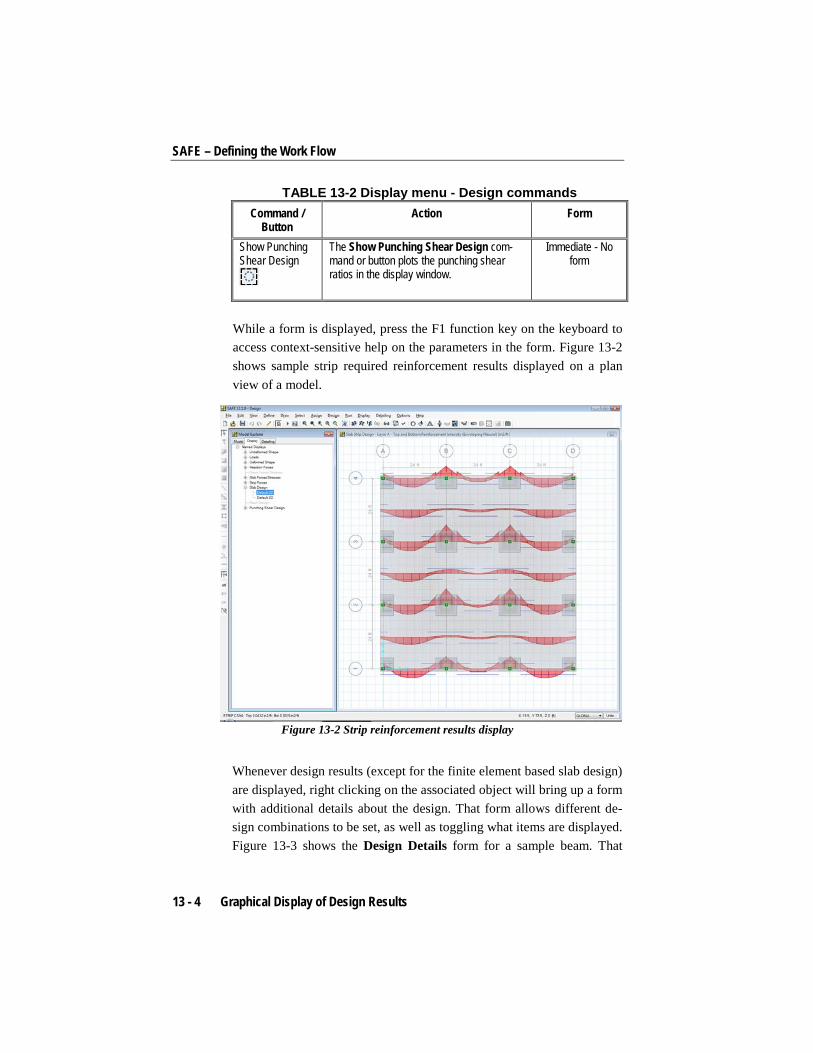
SAFE – Defining the Work Flow
TABLE 13-2 Display menu - Design commands Command /
Button Action Form
Show Punching Shear Design
The Show Punching Shear Design com-mand or button plots the punching shear ratios in the display window.
Immediate - No form
While a form is displayed, press the F1 function key on the keyboard to access context-sensitive help on the parameters in the form. Figure 13-2 shows sample strip required reinforcement results displayed on a plan view of a model.
Figure 13-2 Strip reinforcement results display
Whenever design results (except for the finite element based slab design) are displayed, right clicking on the associated object will bring up a form with additional details about the design. That form allows different de-sign combinations to be set, as well as toggling what items are displayed. Figure 13-3 shows the Design Details form for a sample beam. That
13 - 4 Graphical Display of Design Results

Display Results
form allows the displayed design details to be sent to the printer or saved to an RTF (rich text format) file compatible with Microsoft Word.
Figure 13-3 Design Details form
For beam and strip results, the Design Details form presents summary results on a span-by-span basis. The numerical values below the dia-grams correspond to the maximums in the first quarter, middle half, and last quarter of each span.
13.3 Tabular Display of Results
Both the analysis and design results also can be displayed in tabular for-mat in SAFE. The Display menu > Show Tables command or but-ton presents the Choose Tables for Display form, shown in Figure 13-4. The tree structure can be expanded to reveal various results tables and al-lows the selection of one or more tables of analysis and design results, which subsequently are displayed in a table.
Tabular Display of Results 13 - 5

SAFE – Defining the Work Flow
The displayed tables can be sorted and filtered based on user-defined cri-teria. While a table is displayed, right clicking on a column heading will present a description form, with a brief explanation as to what the col-umn of data is.
Figure 13-4 Choose Tables for Display form
It also is possible to save a Named Set of tables when choosing tables to be displayed. This allows for quick and easy retrieval of a set group of tables the next time that they are desired, without requiring each table in the tree structure to be individually reselected.
13.4 Detailing Results
The reinforcement detailing results are presented in the form of detailed drawing component views that can be accessed from the Detailing tab of the Model Explorer window or from the Detailing menu > Show De-tailing command or button. Those views consist of framing plans, reinforcement plans, section cuts, reinforcement schedules, and rein-
13 - 6 Detailing Results

Display Results
forcement tables. After running the detailing, double clicking on one of the component views in the detailing tree will show it in the display window. Figure 13-5 shows a sample of a slab reinforcement drawing component view on a drawing sheet. Chapter 12 provides additional in-formation on how to modify and customize these views.
Figure 13-5 Detailed reinforcement component view on drawing sheet
Detailing Results 13 - 7

Chapter 14 Output Results and Reports
SAFE provides a variety of methods for outputting analysis, design, and detailing results for further post-processing, presentations, or project submittals. This chapter describes the most commonly used methods for extracting results from a SAFE model.
14.1 Summary Report
A summary report is available at the click of a button using the File menu > Create Report command. This summary report is automatically created by SAFE, is compatible with Microsoft Word, and can contain the following items, depending on the make-up of the model:
Title page containing project information defined from the File menu > Modify/Show Project Information command.
Hyperlinked table of contents listing sections, figures, and tables, along with their associated page number.
Model definition data in tabular format.
Analysis results in tabular format.
Summary Report 14 - 1

SAFE – Defining the Work Flow
Summary design results in tabular format.
Design detail summary sheets
The report also can be generated as HTML or plain text. The contents of the report can be filtered by specifying a predefined group or selecting specific load patterns and load cases. All of those options can be set us-ing the File menu > Report Setup command, which presents the form shown in Figure 14-1.
Figure 14-1 Report Setup Data form
The contents of the report are defined in the SafeReportContents.xml XML file that is installed in the SAFE installation directory. A user-defined contents file can be created by simply taking a copy of the de-fault XML file provided with SAFE, renaming it, and editing the con-tents. The XML can be edited in any text browser or XML editor. For more information on editing or creating an XML report contents file, please refer to the documentation describing the report contents file, available from the Help menu > Documentation command. After a new contents file has been generated, the File menu > Report Setup com-mand can specify that the revised file be used instead of the default file.
14 - 2 Summary Report
Output Results and Reports
In addition to the summary report that is automatically generated by SAFE, there is also an advanced report writer tool that can be accessed from the File menu > Advanced Report Writer command. That tool allows custom reports, including text, pictures, tables, and more, to be defined, saved, and exported to RTF, HTML, or text format.
14.2 Print Graphics and Tables
The graphic displays and tables described in the previous chapter also can be printed directly to a printer or captured to various file formats.
The display in the currently active window can be printed directly to the printer using the File menu > Print Graphics command. This will pro-vide a print preview form that allows for adding text or graphical annota-tions before going to the printer. Graphic displays also may be captured to a file using the File menu > Capture Picture commands. There are different options for defining the region to be captured and the image file type.
The File menu > Print Tables command presents a similar form to the one from the Display menu > Show Tables command. However, the File menu command provides the capability to print a selection of tables directly to the printer or send the tables to an RTF (Word compatible), HTML, or text file. Again, the data can be filtered based on a selection in the model, specified filter criteria, or selected load patterns and load cases.
14.3 Export Results
Analysis and design results also can be exported from SAFE for further post-processing or use in other applications. The File menu > Export Model command has three main options for exporting results.
A display showing results can be exported to a DXF/DWG file compati-ble with CAD applications. The exported data will depend on the current display. The tabular data described in the previous section can be export-
Print Graphics and Tables 14 - 3

SAFE – Defining the Work Flow
ed to either Microsoft Excel (*.xls) or Microsoft Access (*.mdb). The desired tables are chosen and filtered in the same way as previously de-scribed.
14.4 Print and Export Drawings
The drawing sheets generated during the detailing can be printed directly from SAFE. The sheets can be sent to a normal printer or a full size plot-ter. The File menu > Print Drawings command brings up a printing form that allows typical print settings to be defined, as well as the de-sired drawing sheets to be selected.
If further manipulation of the drawings is desired, they can be exported easily to DWG or DXF format for import into CAD applications, using the File menu > Export Drawings command. Similar to the print com-mand, the export form, shown in Figure 14-2, allows the desired draw-ings to be selected and the output format to be specified.
Figure 14-2 Export Drawings form
14 - 4 Print and Export Drawings

Output Results and Reports
As an alternative to using the File menu commands, it is also possible to print or export drawing component views or drawing sheets by right clicking on them in the display window or the Model Explorer window. Right clicking will bring up a context menu that has both print and ex-port commands.
Print and Export Drawings 14 - 5