defense communications engineering center · defense communications engineering center stu-iii...
TRANSCRIPT
DEFENSE COMMUNICATIONS ENGINEERING CENTER
STU-III SYSTEM LEVEL DESCRIPTION00
j2 ""AND
I -NETWORK APPLICATIONS
" NOVEMBER 1986* REVISED JUNE 1988
DTICELECTE f
.JU U 2 71988
H
o APPROVED FOR PUBLIC RELEASE: DISTRIBUTIONUNUMITED
IN
'.

REPORT DOCUMENTATION PAGE1. REPORT SECURITY CLASSIFICATION 1b. RESTRICTIVE MARKINGS
UNCLASSIFIED2a. SECURITY CLASSIFICATION AUTHORITY 3. DISTRIBUTION/AVAILABILITY OF REPORT
DD 254 Approved for Public Release: Distribution
2b. DECLASSIFICATION/DOWNGRADING SCHEDULE Unlimited
a. PERFORMING ORGANIZATION REPORT NUMBER(S) S. MONITORING ORGANIZATION REPORT NUMBERIS)
6a NAME OF PERFORMING ORGANIZATION b1. OFFICE SYMBOL 7a. NAME OF MONITORING ORGANIZATION(If opplicbil. Defense Communications Engineering Center
Computer Sciences Corporation CSC (DCEC)
6c. ADDRESS (City. State and ZIP Codei 7b. ADDRESS (City. State and ZIP Code)
6565 Arlington Boulevard 1860 Wiehle AvenueFalls Church, VA 22046 Reston, VA 22090
84 NAME OF FUNDING/ISPONSORING So. OFFICE SYMBOL 9. PROCUREMENT INSTRUMENT IDENTIFICATION NUMBERORGANIZATION (it applicable
DCEC R630 DCAI00-87-C-0013
8k ADDRESS (City. State and ZIP Code) 10. SOURCE OF FUNDING NOS.
PROGRAM PROJECT TASK WORK UNITReston, VA ELEMENT NO. NO. NO. NO.
87-18A
11. TITLE Il ciude S curit> ChaJssbcatiOni
STU-III System Level Description and Network Applications
12. PERSONAL AUTHORIS;
Wilmot, Roger138& TYPE OF REPORT 13b. TIME COVERED 14. DATE OF REPORT fYr., Mo., Day) 15. PAGE COUNT
Technical FROM 1988 TO 880630 3516 SUPPLEMENTARY NOTATION
17 COSATI CODES 18. SUBJECT TERMS lCorit'nur on reverse if neceuary' and identify by block numberi
FIELD O GROUP SUB GR STU-III, RED Switch, TRI-TAC, Radio Wireline Interface,IVSN, DSN, Conferencing
19 ABSTRACT rContinue on reverse if ncessary and identify by block numberI
3 This paper serves as the system level description of the Secure Terminal Unit Type III
(STU-III) and its interfaces in a variety of DoD switched voice network appl'cations.
The STU-III terminal is being developed by the National Security Agenc:r7NA-6nd is
intended to replace several thousand existing analog clear voice telephone instruments
in the DoD. Its operation and interface to the switched networks is essentially the
same as for existing or planned clear voice telephones. The STU-III family of terminals
includes two types of Low Cost Terminals (LCT-l and LCT-2), a STU-II compatible terminal
(STU-III/A) and a ruggedized mobile/portable terminal (STU-III/MPT). The LCT-l is
intended to be the primary DoD secure voice terminal, whereas the STU-III/A and STU-III/
MPT will be used for special applications, e.g., for interoperability with the NATO
STU-II terminals and tactical operations requirements.
20 DISTR, BUTION/AVAILABI LITY OF ABSTRACT 21. ABSTRACT SECURITY CLASSIFICATION
UNCLASSIFIED/UNLIMITED 7 SAME AS RPT. 9' DTIC USERS 0 UNCLASSIFIED
22s NaME OF RESPONSIBLE INDIVIDUAL 22b. TELEPHONE NUMBER 22c. OFFICE SYMBOL(include Arra Code)
Mr. Bobby Donald (703) 437-2150 R630

DCS SWITCHED NETWORKSSYSTEMS ENGINEERING AND TECHNICAL ASSISTANCE
STU-III SYSTEM LEVEL DESCRIPTION AND NETWORK APPLICATION9
REVISED*- JUNE 1988
Prepared for:
DEFENSE COMMUNICATIONS AGENCYDEFENSE COMMUNICATIONS ENGINEERING CENTER
1860 WIEHLE AVENUERESTON, VIRGINIA 22090
Under
Contract No. DCA100-87-C-0013
Prepared by:
Computer Sciences Corporation- 3160 Fairview Park Drive* Falls Church, Virginia 22042
'-."
. r

TABLE OF CONTENTS
Page
Section 1- Introduction......................................... 1
Section 2 - STU-III Physical Description and Basic Features. 2
2.1 Physical Description................................... 22.2 STU-III Features and options........................... 2
Section 3 - System Overview, Interfaces, and Call Procedures 7
3.1 System Overview......................................... 73.2 STU-III Network Interfaces............................. 7
73.2.1 Secure Nonsecure Call Features........................ 123.3 STU-III to STU-III Call Procedures.................... 163.4 Interface to RED Switches.............................. 163.4.1 Trunk Interface Mode ........................ 16
03.4.2 RED Switch Interface Call Descriptions for TrunkInterface Mode..............................17
3.4.3 User Access Line Interface Mode....................... 193.5 Interface to DSN STU-III Conference Units............. 193.5.1 Interface Description.................................. 203.5.2 Conference Call Description........................... 203.6 Tactical Radio/Wireline Interfaces (RWI's) to
ANDVT/VINSON......................................... 203.6.1 Generalized RWI Description........................... 223.6.2 RWI Call Description................................... 24
Q. ~3.7 STU-III Interface to TRI-TAC (AN/TTC-39).............. 243.7.1 STU-III Deployment with TRI-TAC AN/TTC-39............. 243.7.2 Manual RED Switch Interface........................... 253.8 NATO Interface......................................... 28
.,~.Section 4 - Transmission........................................ 31
Section 5 - Status of STU-III Logistics Support Planning . 32
5.1 Low Cost Terminal (LCT)................................ 325.2 STU-III/A and STU-III/MPT.............................. 32
Bibliography..................................................... 33
* Glossary of Terms and Abbreviations............................. 34
D iC TAM~
U1miounce d
IN:SPECTEDA Dj stribiltion/
Availatilit,, Code
I Avnil and/or'
Dist Special
w Ii I0ii If 1II
II C 1 1 1 1 1 ,1 1 1 1g-w- L=&Nm

LIST OF ILLUSTRATIONSFigure Page
1 STU-III Network Applications ............................ 82 STU-III Two-Wire Network Interface .................... 103 STU-III Four-Wire Network Interface ................... 114 RED Switch Interface to Switched Networks ............. 185 Current General Purpose STU-III Conference Approach 216 Tactical RWI Interoperability .......................... 237 STU-III/TTC-39 Interoperability (1) ................... 268 STU-III/TTC-39 Interoperability (2) ................... 279 NATO Interoperability .............................. 29
LIST OF TABLES
1 Vendor Data Port Modes (LCT-1) .......................... 42 STU-III/LCT-1, STU-III/A and STU-III/MPT
Interconnection Matrix ............................... 93 STU-III LCT-I Application Configurations .............. 134 LCT-l Interface Configurations ......................... 14
C
~iii

4
SECTION 1 - INTRODUCTION
This paper serves as the system level description of the
Secure Terminal Unit Type III (STU-III) and its interfaces in a
variety of DoD switched voice network applications. The STU-III
f terminal is being developed by the National Security Agency (NSA)
and is intended to replace several thousand existing analog clearri voice telephone instruments in the DoD. Its operation and
interface to the switched networks is essentially the same as for
existing or planned clear voice telephones. Installation of a
STU-III in the United States can be very simple; normally,installation for a two-wire application consists only of inserting
I'. a telephone connector (e.g., RJ11C) and an AC power plug into the
appropriate receptacles. The STU-III family of terminals includes
two types ot Low Cost Terminals (LCT-1 and LCT-2), a STU-II
compatible terminal (STU-III/A), and a ruggedized mobile/portable
terminal (STU-III/MPT). The STU-III/LCT-I, STU-III/A, and
STU-III/MPT are intended for all levels of government classified
traffic. The STU-III/LCT-2 is intended for sensitive unclassified
traffic. The LCT-1 and the LCT-2 units will be available in at
least three vendor variations; i.e., AT&T, Motorola, and RCA. The
STU-III/A is in the Low Rate Initial Production (LRIP) phase,
deliveries are expected by October, 1989 from Motorola. The MPT
.p.is currently in the development phase with Motorola. A production- contract is anticipated in early 1989. All STU-III terminals are
interoperable at 2.4 kb/s using an enhanced Linear Predictive
Coder voice algorithm. The LCT-l is intended to be the primary
DoD secure voice terminal, whereas the STU-III/A and STU-III/MPT
will be used for special applications (e.g., for interoperability
*_ with the NATO STU-II terminals and tactical operations
. requirements.
1, 1
04

SECTION 2 - STU-III PHYSICAL DESCRIPTION AND BASIC FEATURES
2.1 PHYSICAL DESCRIPTION
The STU-III consists of a deskset, handset, and, depending
upon the vendor and/or location, a separate AC power adapter. The
*approximate range of physical parameters is: 225-900 cubic
inches, 8-15 lbs., and 14-30 watts. This range of parameters
varies respectively in size, weight, and power depending upon the
vendor and the type of terminal provided (i.e., STU-III/LCT,
SSTU-III/A, or STU-III/MPT).
2.2 STU-III FEATURES AND OPTIONS
The STU-III terminals will incorporate the following features
and options:
i. STU-III/LCT-1
a. Common Features
(1) Clear and secure voice operating modes
(2) Digital voice processing based on Linear
Predictive Coding, Enhanced (LPC-10e) at 2.4
kb/s for the secure mode
(3) Full-duplex operation over two-wire access
lines, with internal echo cancellation
(4) Half-duplex operation (VOX) over two-wire access
* lines
J r (5) Secure data capability at 2.4 kb/s, synchronous.(6) EMI/TEMPEST protection
* (7) Crypto keying using the FIREFLY II algorithm
(8) Precedence tone dialing for two- and four-wire
applications
2
0,
* .V. r* *.. W..

(9) Preempt tone recognition
(10) Secure dialing mode, which allows address
information to be passed securely to a distant
interface, e.g., conference bridge or RED switch.
b. Common Options
(1) Foreign country operation by meeting elecLrical,
functional, and power requirements of host
country
(2) Four-wire AUTOVON/DSN operation
(3) Abbreviated dialing and storage of several
frequently called telephone numbers
(4) HEMP protection
(5) Multiline compatibility with industry standard
(Bell System's 1A2) Key Telephone System.
c. Vendor Available Options
(1) Dual Homing capability implemented via four-wire
AUTOVON/DSN and two-wire DSN/public switched
networks (RCA)
(2) Digital voice processing at 4.8 kb/s using
non-LPC algorithm (AT&T)
(3) Secure and nonsecure data options (See Table 1)
(4) Cellular radio model including cellular radio
0N with capabilities for signaling, vehicular
mounting, and power (Motorola)
(5) RED Interface Terminal (RIT) capabilities
including the capability to remote the RED
4 analog and RED digital voice outputs, deskset
dialing, and control functions to another
location [The basic AT&T and RCA terminals
3

Table 1. Vendor Data Port Modes (LCT-l)
SPEED MODE FEC AT&T MOT RCA
SYNC NO 2
4800 YES
ASYNC NO X2
YESSYNC NO X _"- 2400xx
YESASYNC NO xX X
YESSYNC NO
120YES X
ASYNC NO X X
SYNC NO
600YES X
ASYNC NO X
YESI SYNCS300 NO
YES XASYNC N ____ ____NO X X
SYNC NOYES ______X15 ASYNC NoE xNO xs
YES _
* SYNC NO-, ,: 5YES X__ _ _ _
NOTES: 1. FORWARD ERROR CORRECTION2. CLEAR DATA CAPABILITY
4
pV2
0Z _,,

have this capability; Motorola has a separately
configured, rack-mountable terminal, Automatic
Remote Secure Telephone Unit (ARSTU), to provide
IN this capability. The remote interface for each
vendor's RIT is different and is defined in
separate interface control documents.]
(6) Plain Old Telephone Service (POTS) during local
AC power failure (Motorola)
2. STU-III/A - The STU-III/A has the same common features
and options, except for the multiline option, of the
STU-III/LCT-1, plus the following:
a. Secure Asynchronous Data at 300, 1200 and 2400 b/s
b. STU-II BELLFIELD keying capability
c. STU-II NET mode
d. STU-II NET MULTIPOINT mode. [The NET MULTIPOINT (NET
BROADCAST) mode of operation provides for half-duplex
push-to-talk, broadcast communications between two or
more STU-III/A's holding common NET keys.]
3. STU-III/MPT - The STU-III/MPT has the same common
features and options, except for the multiline option, of
the STU-III/LCT-1 plus the following:
a. Secure Asynchronous Data at 300, 1200 and 2400 b/s
b. STU-II NET MULTIPOINT mode
C. Black digital interface (RS-449/232/MIL-STD-188C) toi connect to an external device such as a modemd. Cellular interface directly compatible with the
MOTOROLA 6000 Mini-Tac cellular transceiver'I
e. Interface to external military radios
I5

f. STU-III Dedicated mode with ring and answer
capability for "hot line" applications [Either a
switch connection must be held or a dedicated circuit
must be provided in order to effect this mode of
operation. This mode, once established, will allow
the users to physically go on-hook while still
maintaining the connection. When either user goes
off hook and selects clear or secure, a ring
indication is sent to the distant terminal alerting
the user of an incoming call.]
0

A" SECTION 3 - SYSTEM OVERVIEW, INTERFACES, AND CALL PROCEDURES
.3.1 SYSTEM OVERVIEW
Figure 1 shows the various applications of the STU-III in the
Defense Communications System (DCS) and other networks, either asan end terminal on the backbone network switches and PBX's, or as
a RED Interface Terminal (RIT) for interfaces to other networks.
As shown, the STU-III in its RED Interface Terminal configuration
will be integrated into the RED switch and the STU-III conference
bridge to provide access for these devices to the switched voice
networks and to other STU-III's or interface devices. The
. -.' interconnection matrix for the STU-III's is shown in Table 2. As
indicated, all STU-III's can directly interoperate with each other
via the switched networks. Only the STU-III/A can directly
connect via the DSN/IVSN networks to a NATO KY-71 (STU-II). A
manual Radio Wireline Interface (RWI) will be required to allow
the STU-III to interoperate with tactical VINSON/ANDVT terminals.
Direct automatic interoperability will be possible with the RED
switch and the STU-III conference bridges via the RIT. Further
i' ,' explanation of these interconnections and associated call
m [procedures is provided in subsequent paragraphs. It is intended
that the STU-III will utilize existing voice grade telephone
*. access lines; new facilities, if required, need not differ fromr. those required by a normal telephone installation.
* 3.2 STU-III NETWORK INTERFACES
As indicated, the STU-III (except for the MPT) is a
replacement for existing clear voice telephone terminals. In
general, the STU-III's have two basic termination interfaces -0 i.e., two- and four-wire - applicable to the switched voice DoD,
U.S., and foreign public networks. These are shown in Figures 2
and 3. The two-wire mode is full-duplex with a manual fallback tohalf-duplex. The predominant utilization of the STU-III will be
7

OX
p 0 :
U)Uu-
0~0
* 0.
'-4
LiiI.-i
IM w
>>
- ~2P- V2* zz
:u1j0.(
0w:w
I.- 0 ~
0 WJ
8 0

z CAt.
0 uA
LLJU. 0D L A(
IxJ 41 'l/0 "0 i "
z 0 z 0 ) 4
- l cx4
E- I W
C3 cc II-r3cl
LA 0 >- L~j-1 0 L.J0.z z 2 0.d
LiL - - -- 0
mx LAu L,.i J0 .
> 1 01 CX. Li ) 0 - '
m-4 he Zi004L
4-I-Lo Li.) Li4
EQ Li -j W L
ad 74-0L.
4) -. V-
1-4- 4-
c -4
1- P- -.. J
Lii .j 4L
C.-,
-I)-
Li Li. La
u Aj
cc 4- 4-
Li Li LO -~
4~ <A - LJ
-j -
0 X
0i 9
19,~~~C C3 C, ''. 7 ~ "

CPE TRANSMISSION DSN
LEADS -OPTIONAL) PABX
TTC-39 (ANALOG)
TWO WIRE VOICE GRADE
v COMMERCIAL TELEPHONE INTERFACE
PER EIA STANDARD RS-470
PROGRAMMABLE OPTIONS FOR
PTT COMPATIBILITY
MODULAR JACK
DTMF OR DIAL PULSE
DC LOOP SUPERVISION
FIGURE 2A. A SINGLE LINE INTERFACE
CPE TRANSMISSION
N SERVICE j
UNITN
6 BUTTON KEY PADL(5 LINES PLUS HOLD)
50 PIN CONNECTORCOMPATIBLE WITH 1A2 KEY SYSTEMS
~FIGURE 2B. A MULTI-LINE INTERFACE
LEGEND
U CPE CUSTOMER PREMISE EQUIPMENTPOT PLAIN OLD TELEPHONE
1 Figure 2. STU-III Two-Wire Network Interface
01
6 BUTO KE PA TT-9AALG
CPE TRANSMISSION
A1
A
E r Mis SUPERVISIONS
LG
INAEFAU AUTVR LINE INTERFACE UNIT
CPE CUSTOMER PREMISE EQUIPMENT
SIG SIGNALING UNIT
'
Fiue3 T-I orWr ewr nefc-IL EGN
ALIU AUTOON INE NTEFACEUNI
CP UTMRPEMS QIMN
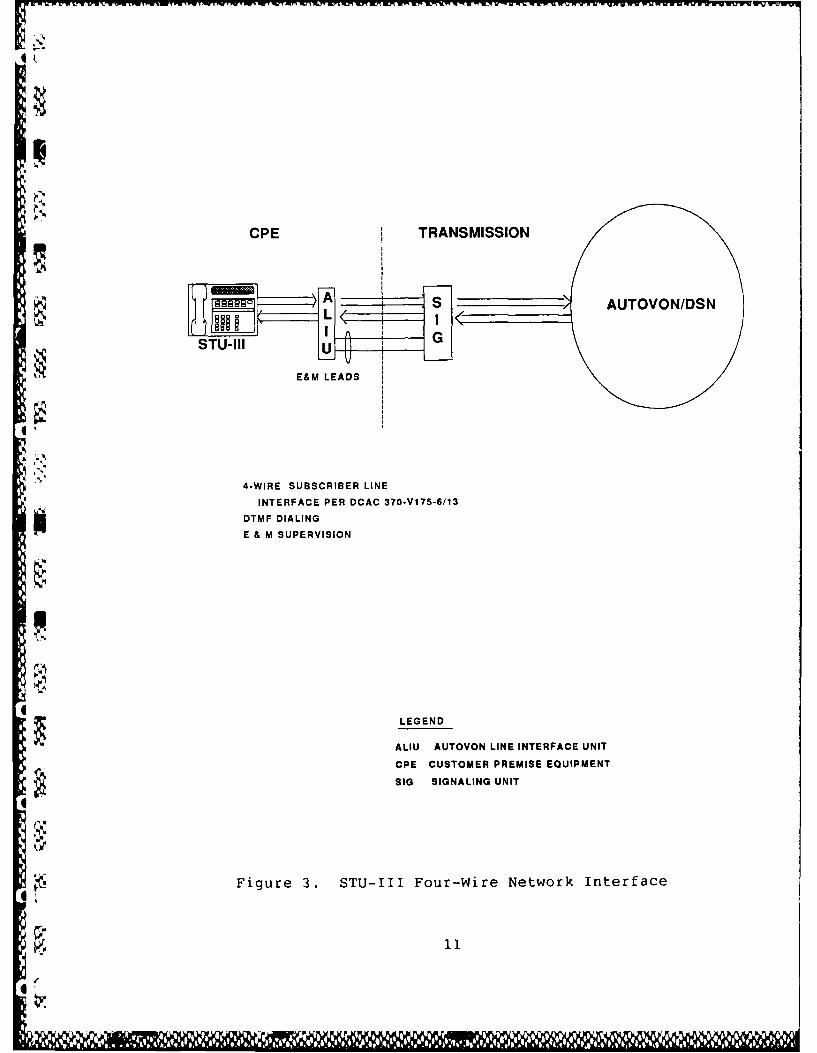
in the two-wire full-duplex mode. The interfaces shown are
applicable to all vendor models of the STU-III. The two-wire
interface shown in Figure 2 is the standard commercial interface
Y, for single line two-wire telephone lines in accordance with EIA
Standard RS-470. For overseas applications, the terminal
interface will be programmable and adaptable to meet foreign
public switched networks (PSN) variations, for example, signal
4delays or levels. This interface will allow connection to the
AUTOVON, DSN, PSN's, PABX's and the AN/TTC-39 analog matrix. The
STU-III's four-wire interface shown in Figure 3 is identical to
the standard AUTOVON/DSN interfaces as specified in DCAC
370-V175-13. Currently, the AUTOVON four-wire terminals (with
I. Multilevel Precedence and Preemption (MLPP) capability) are
primarily for C2 subscribers; some will be replaced in the
initial application of STU-III's. In general, the four-wire
STU-III will require a STU-II AUTOVON Line Interface Unit (ALIU).
However, each installation must be considered on a case-by-case
basis. The NSA STU-III TELCO Connection and General Information
Report, 4 March 1988, provides specific details on each type of
ALIU that will work with the STU-III and how each is to be wired.
This document also provides interface details on how to connect
various terminal interfaces (i.e., two-wire, four-wire, and
multiline key systems). Tables 3 and 4 show the various
STU-III/LCT wireline interfaces and interface configurations.
3.2.1 Secure Nonsecure Call Features
Depending on the type central office, various features are
provided to the user by modern automatic central office equipment
that supports call processing. These features will vary based on
the type of central office or PBX to which the STU-III is
connected. However, there is a basic set that is generally found
on modern equipment and is specified in the DSN Generic Switch
Specification. Of these features, all will work with the STU-III
in the clear mode. In the secure mode, conferencing (to include
12

CL >
to > 1 0 C0 cCO & cm 00
0. w. C fa- 0.t
4)0>0 3: 0) c CL L= E t 0 L ID w0
V. CL C 0 '4) 4-0 c4
0> XL L -W 0 t n
::5 .1 .C ; a) 0n I- 'm iUrd W 411 0. 0 - .J E- -J CC 4
L1 04 4) ", m. 0 IA w U- > 0 Lc. .i 0 LA j 4) C. ;; .u n cLA
4-4~L ~ ( 0 in 0G . 00 CL.
0u
0
z0 0)
z > 'o 4) 0-
E 0d x 00.L
0 C .C i 0~C -4'
- 4.L. cm
C.. C C- to 00C t
HA Cf A LAO .- *. C~A c-.1z.D =.U ml. 0.W 00 0L a;
H0 0--; 0 0D 1 01 0. 0Li~~~~t 0 ;L 1 L
L. 4.
.L00Li 3i L.: Li. x
13

4,7
GJ 4'
cu- 4- CU 0
Imx 0 -4'G U
L( c M4 0.. 4 C
m1~* '*.i .0 0 m0 E4G 'i.
iv C 0 4,, L. CQ w 0 C.
c 41 41 041
(V 4-. z ) 4
c~ 0.3 -en tw~~~~~- C..-L1 2 ) )C
*-D CDC CiLD
4-ii
0' C'J
LJ'41 0
0 00 . 0 .0 .0
0.L CL 4'4.4EUi Li EU E E EC CI-.
.0 ('.1 0 0 L%0 Li C9i Licc O L)4
clil
: CL
E- z C4 J
Ia . o 0. C CW, : ,
, - 4' m as DwI . Cl - *-z L
m .S' im' 0100 C. I- (a- C0
4 0
I
Ii ~j 0 NLNciLUL"i 01. Li 0L. Li00 iC.
14

L - C L
L 0. P
0~0 ~ 4.) L.
v. toL.
wU w z41 40)L c . a
14 Lc 41 :,. s 41
01U 0o 0 0.No > r- .- I- 4)
x 041. QC L
W L.. 4)
> >. :D .
3 04
0*u
0 CI r -4i 1
uj 1z
0 -0X
LC 4- 4-11
y -4.0>
to
i u 0 04 415
d" 11,61 1, 1 M NK

three party), call waiting, precedence call waiting, and attendant
busy override features will not work. All secure conference callsmust use a STU-III digital conference bridge (see paragraph 6).
The other features listed will not work because their associatedtones are not audible to the STU-TII user when the terminal is in
the secure mode. A preempt tone will be detected and both
visually and audibly indicated to the user by the STU-III.
3.3 STU-III to STU-III CALL PROCEDURES
Dialing procedures for the STU-III a-e similar to those usedfor the normal telephone. Calls are established as plain analog
connections through the network through use of the DSN numbering
plan and call procedures. The user goes off-hook, dials*precedence (if applicable), dials the called party number,
converses with the called party in the clear mode, and thenselects the secure mode. Synchronization for the secure mode willthen be accomplished by the STU-III's and will take about 15
seconds. Normally, all calls are automatically established asfull-duplex; however, half-duplex operation may be selected
manually as a backup when telephone lines are encountered that dop
not support full-duplex operation, such as excessive echo or echo
suppressors that cannot be disabled.
3.4 INTERFACE TO RED SWITCHES
RED switches provide secure voice service through use ofphysically secure switching and distribution facilities. Both
existing and new DoD RED Switch Project (RSP) switches thatrequire access to the DSN will be equipped with STU-III securedinterfaces. These interfaces may operate in either a trunk mode
or a user access line mode to DSN.
3.4.1 Trunk Interface Mode
This interface mode provides automatic network in and out
dialing between the RED Switch and DSN, and is the preferred* imethod of operation for the RSP switches.
16
f.
061 iM- a
V
3.4.1.1 Interface Description
The RED Switch will appear as an End Office (EO) interface to
the DSN (see Figure 4). Each trunk will be equipped with a RED
Interface Terminal (RIT) and an interface applique function to be
provided integral to the RED Switch. The RIT is a configuration
of the STU-III that provides remotable RED digital audio, control,
and status inputs/outputs. The applique function provides
compatible interfaces to the RIT, the RED Switch trunk port, and
the DSN trunk. The applique also provides monitoring and control
of the RIT; provides RED/BLACK isolation; and provides processing
of signaling, supervision, and addressing information between the
RED Switch and BLACK DSN trunk.
3.4.2 RED Switch Interface Call Descriptions for Trunk InterfaceMode
$3.4.2.1 RED Switch User to STU-III
The calling RED Switch user dials a precedence digit, a
two-digit access code, and the seven-digit DSN number of the
called STU-III. The switch seizes an idle interface trunk and
forwards the call data to the interface applique which isolates
and forwards the call data to DSN. The DSN then completes the
connection to the distant STU-III. When the called STU-III
answers, both the RIT and the called STU-III go to the secure
mode. The RED Switch then connects the calling RED Switch user to
the interface trunk, allowing secure communications to begin.
3.4.2.2 STU-III to RED Switch User
The calling STU-III dials a precedence digit and the
seven-digit DSN number of the called RED Switch user. The DSN
4 routes the call to an idle RED Switch trunk and forwards the call
precedence and addressing information to the interface applique.
The interface applique in turn isolates and forwards the
information to the RED Switch for processing. The RIT and calling
17
L 1 1k1)H 1

z
zz
4
z w =
W L ~I--C
4 4-)
0 00
z 0o 0 0 0-1 -
-C 44
ULttU-0
C)WLLR QH
U) (L) 4)
*LJ LLEI -C 1 0W W
18-

r'vra ~ ~ ~ ~ ~ ~ ~ ~~1 WWIr rmr Ir p. 17Viwrnnin i. Y, l Pb-7nPV Is i-fftwb. r V V LVV Icr vWvi c VWV VW U .- L-W6.WWW VV VW
STU-III go to the secure mode automatically, and the RED Switch
rings the called party. The RED Switch completes the connection
when the called party answers; secure communications may then
begin.
3.4.3 User Access Line Interface Mode
The capability will also be provided at the RED Switches to
provide a user access line interface to the DSN from the RED
Switch, either two- or four-wire, via the RIT and associated
interface applique. In this case the RED Switch looks like a user
station to DSN, as opposed to another switch. This interface
could be used in cases where automatic network in-dialing with
precedence is not required, e.g., access through the base PABX.
Outgoing calls may be either operator-assisted or automatic
from the RED Switch user. Incoming calls may be operator-assisted
in the secure mode or automatic when the calling STU-III is in the
Secure Dial mode. Any or all of these options are available in
the RSP switches.
3.5 INTERFACE TO DSN STU-III CONFERENCE UNITSSTU-III users will be provided a secure conferencing
capability as a service feature of the DSN. Initially, the
capability will be provided by three geographically distributed,
operator-controlled AN/FTC-52 digital conference units. The
conference units will employ a RED digital broadcast conference
protocol. This digital technique eliminates the need for RED
analog tandem connection of LPC-processed speech between conferees
and the associated voice quality degradation which would occur.
Conference units will be interfaced to the DSN through RED
Interface Terminals (RIT's). One conference unit is planned to be
provided in the CONUS, one in Europe, and one in the Pacific to
provide an operational capability and to gather usage data to
further define general purpose STU-III conferencing requirements
*O for an expanded STU-III population.
19

3.5.1 Interface Description
The conference unit interface to the DSN (see Figure 5) will
consist of a number of two-wire DSN voice user lines. Each line
will be equipped with an RIT interfaced to an operator's
conference control console. The control console will provide the
operator with the capability to control and monitor the RIT and
AN/FTC-52; provide RED/BLACK isolation; and process signaling,
,supervision, and addressing between the conference unit and BLACK
DSN line. The lines will be placed in a common hunt group within
DSN such that only one telephone number is required to access the
conference unit.
i . 3.5.2 Conference Call Description
0 To initiate a conference, the conference originator dials a
W, precedence digit and the seven-digit DSN number of the conferenceunit location. DSN completes the connection to the conference
unit, the call is answered by the conference unit operator, and
both the RIT and the calling STU-III go to the secure mode. The
originator then provides the operator with the telephone numbers
of the desired conferees. The conference unit operator then calls
each conferee through separate RIT's. When each conferee answers,
the operator announces the conference, then both the RIT and the
called STU-III go to the secure mode and the operator connects the
conferee to the conference unit. Once all conferees have
answered, the conference may begin. During the conference, the
", .conference unit monitors the incoming RED digital signal from each
interface line to detect speech activity. The active (first
active if more than one) speaker's digital input is then broadcast
to all other conferees. Once the active speaker yields, the
conference unit is available to be seized by a responding conferee.
3.6 TACTICAL RADIOG'WIRELINE 1INTEIRFACES (RWI's) TO ANDVT/VINSON
* ~,UHF, VHF, and HF radio and satellite broadcast networks
provide connectivity between airborne and naval forces, and access
02
Wi.'' 7 ~*

'Vl Znw wl~ - -wl . v- I . ,w -n
LUu
Ui:; 0
Lu 00
I-o
L) C)
/4 U w
C/) CC)c'5 U)w 7~
0
C..)V7
.4 S
0a
w "4
4
C',,
Zuj
w LLu0
0 0z0()l
LL ELL~ UA
* . z
0 0Z
04z zFA
0

to the DCS switched networks via operator-assisted radio/wireline
interface stations. Network secure voice services will be
provided by the 16 kb/s VINSON and the 2.4 kb/s ANDVT, which are
. C[" ° being introduced into these networks. The STU-III terminal will
employ a common analog-to-digital algorithm at 2.4 kb/s with the
ANDVT; thus, they will provide a good speech quality RED digital
*connection to the ANDVT. Connections to VINSON terminals will
require an analog breakout between the 2.4 kb/s STU-III terminal
.and the 16 kb/s VINSON. Radio/wireline interface stations may be
equipped with one or more STU-III RED Interface Terminals (RIT's)
to provide secure access to and from STU-III users (see Figure
6). Interface consoles will be developed by the cognizant
military departments to provide an operator-controlled interface
between the RIT's and the secure radio equipment at each station.
The capabilities required of the interface console will vary
between RWI stations based on the number of access lines required
Q and the number and type of secure radio equipments provided. The
description below covers the generalized case with multiple access
- lines, each capable of being connected either to an ANDVT via a
" / . RED digital interconnect or to any secure link via a RED analog
interconnect.
3.6.1 Generalized RWI Description
The RWI will consist of RIT's for STU-II: interoperability,
an operator console for establishment and control of connections,
* and network radio COMSEC as required for interoperability with the
radio networks being served. Optionally, each RIT may connect to
the switched networks via a four-wire AUTOVON/DSN line or two-wirefacilities. The interface console will provide two basic types of
connections: (1) RED digital connections between STU-III's and
ANDVT's; and (2) RED analog connections between STU-III's and
- VINSON's. The console will interface the RED KG, digital speech,
4 analog speech, control, and status input/outputs of each RIT and
will contain the necessary circuitry to monitor and control each
k 22
0V

Ux' z4 zLL. z 0,
w_ 0 * C L
0 2 00 0 24 >.
o F4
20 - -
~ 0 C
R.- 2EM 0
0uJCP- 0 00 0 0o 5w-w
z 4 4.)
0 ZL z00 le 0 I. z i C
Ul) UJ 41 54E 04z0 > Z 0 >>. W
*6 LAI 00=4wwwz< 40 0Z M-~ a, Q
* < 0 0
6~ .,..> W a,
00 >0 0 0--i0 4c oa.Z > -41E4
= U - - 0 Z j Z > h
00~
20 0 0 -0)a 0 4g ZJ
-X 0- i- u
LU 0 j0 C
0 0a'%S'~~ 6 oJ
~~ -w0
0 4 O0 cc 0 0
*l Cd0
.)
z 0 0 >z 4
UL
UU
6 23
.!J
RIT, as required, for operator initiation and receipt of STU-III
calls and for the establishment and termination of interface
connections. The console and its RIT's will be capable of
interoperating with STU-III terminals in the secure mode. The
console will provide for network push-to-talk control through
digital speech detection for full-duplex connections, when
required. For RED digital interfaces, the console will buffer
*timing differences between the wireline and radio links to
minimize the probability of speech clipping. The console will
provide for the automatic termination of a call upon receipt of a
release message by the RIT or of a preempt signal.
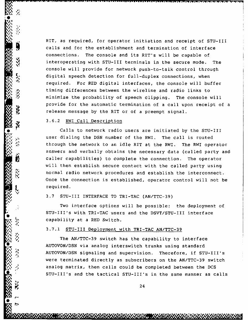
3.6.2 RWI Call Description
Calls to network radio users are initiated by the STU-III
user dialing the DSN number of the RWI. The call is routed
through the network to an idle RIT at the RWI. The RWI operator
answers and verbally obtains the necessary data (called party and
caller capabilities) to complete the connection. The operator
will then establish secure contact with the called party using
normal radio network procedures and establish the interconnect.
Once the connection is established, operator control will not be
required.
3.7 STU-III INTERFACE TO TRI-TAC (AN/TTC-39)
Two interface options will be possible: the deployment of
STU-III's with TRI-TAC users and the DSVT/STU-III interface
capability at a RED Switch.
3.7.1 STU-III Deployment with TRI-TAC AN/TTC-39
The AN/TTC-39 switch has the capability to interface
AUTOVON/DSN via analog interswitch trunks using standard
AUTOVON/DSN signaling and supervision. Therefore, if STU-III's
4, were terminated directly as subscribers on the AN/TTC-39 switch
analog matrix, then calls could be completed between the DCS
STU-III's and the tactical STU-III's in the same manner as calls
24
0R

- iW.
between STU-III's in the DCS (see Figure 7). Tactical users would
have to be equipped with STU-III's as well as their own Digital
Subscriber Voice Terminal (DSVT). The capability of the STU-III
to operate over the TRI-TAC system in this manner is being tested;
preliminary results have been satisfactory.
3.7.2 Manual RED Switch Interface
The RED Switch can provide an operator-assisted interface
.capability between the DSVT subscribers served by a TRI-TAC
equipped (AN/TTC-39) switched network and STU-III subscribers
served by the DSN or commercial networks (see Figure 8). The REDv Switch will interface the tactical network through a DSVT (CVSD
algorithm) interface via access lines or trunks operating at 16 or
32 kb/s and will be capable of interoperating with any
DSVT-compatible tactical secure voice element. The RED Switch
will interface DSN through an RIT (STU-III) operating at 2.4 kb/s
(LPC algorithm). The internetwork connection between the RIT and
DSVT interface lines will be made by the operator at the RED
analog level. This arrangement would require authorization by the
,. RED Switch operating agency. The quality of voice, speed of
service, and security procedures are affected.
3.7.2.1 Quality of Voice
Voice quality between a STU-III user and a DSVT user at 32
kb/s is expected to be fair to good. Connections with the DSVT at16 kb/s would probably be poor to unacceptable.
3.7.2.2 Speed of Service
Since all calls will be manually processed, the call set-up
S., ~ time will be significantly extended.
3.7.2.3 Security
STU-III calls to and from the RED Switch will be
automatically restricted to terminals that are keyed (CIK
inserted) SECRET or higher. Calls extended to or from tactical
25

-- --- - - - - - - - ------ --------------- ----
w V)
cocc
LUL00
LU i zz~ I.
CC..
I. z
0 p 0
U) >tuHz 0 >-i'-4
UA 4;
C, 0
>4~ 4 3U
w w LU
o z.
v W26
I ll I'li l I i I -i-

t~www~- ~ ,*Wow lW tw'1 .w - I rr~r~T n, ' ~ ~ w~ , ri j IRi n .2 R
NN
z
2 4g4
CO CO
00* IX
u-4
'C0 0 H
U'
Z~ 0Co -
cc w 0
,P227
w .

users will also have to be limited to terminals that are keyed
SECRET or higher.
3.8 NATO INTERFACE
The planned NATO secure voice capability is based on the use
of STU-II type terminals and BELLFIELD keying. NATO
interoperability for a limited set of DoD users will be provided
by the STU-III/A, which has a STU-II compatible voice algorithm at
2.4 kb/s and both the BELLFIELD and FIREFLY keying processes. The
NATO STU-II will be terminated as a four-wire drop on the NATO
Initial Voice Switched Network (IVSN) and will utilize a four-wire
line adapter identical to the AUTOVON Line Interface Unit (ALIU)
(see Figure 9). The STU-III/A must also be terminated as a
four-wire drop on DSN, utilizing an ALIU, if full duplex operation
is required.
The IVSN and AUTOVON/DSN will be interfaced through a device
called the IVSN/DSN Interface Device (IDID). The IDID can be
Ithought of as a subscriber on both the IVSN and AUTOVON/DSN
networks. In this role, the IDID essentially answers a call from
either network and then goes off-hook to the other network,
allowing a call to be placed into the other network after
receiving a second-dial tone. The interface will permit
precedence calls to be placed through both networks from either
IVSN or AUTOVON/DSN subscribers.
The calling process from either network follows: Each IDID
gateway will appear as a subscriber terminal and will have a
network address; each circuit will be classmarked at the highest
precedence level authorized. In a call between a STU-III/A and a
NATO STU-II terminal, the BELLFIELD two-call procedure will be
used. This procedure requires that the calling user dial the
called party's five-digit ID number, its precedence (if
applicable), and then the number of the gateway. The calling
terminal will then automatically dial the BELLFIELD Key
28
r0

00
j< 0~
Low0Il'(WZ
Fz<
z 0LM-IpLU LUo
Z 1_ W D
:3z >z :i :0:
00 0
wt..C
~~0
I029
Distribution Center (KDC) to obtain key information and establish
a second call to the called gateway IDID. When the second dial
tone is heard, the caller will enter the precedence digit, if
applicable, and number of the subscriber in the destination
network. Since the STU-III/A and STU-II are directly compatible
in the BELLFIELD mode, they can then automatically synchronize and
go into the secure mode. The U.S. STU-IIIA must be classmarked at
the KDC to allow interconnection to the NATO STU-II.
The NATO STU-II's do not have the capability to enter a
precedence digit after a second dial tone (unless the terminal is
modified or a separate DTMF key pad is added). Therefore, the
STU-II user will be able to use precedence only to get to the
gateway, not into the interconnected network.
30
r"

SECTION 4 - TRANSMISSION
The STU-III modem design incorporates both near- and far-end
echo cancellation; thus, it can provide full duplex operation over
two-wire access lines as well as four-wire lines. Conditioned
lines are not required; however, the following network aspects
should be considered:
1. Network echo-suppressors and echo-cancellers should be
capable of being tone disabled. The STU-III sends a
disabling tone during its initial set-up protocol.
2. Tandem links of ADPCM should not exceed four (CCITT
Recommendations G.113 and G.721).
* 3. Tandem links of satellite transmission should not exceed
two.
4. The effects of TASI on the STU-III are still being
tested; however, the effect of the STU-III on TASI will
be to reduce the efficiency of the TASI, since the
STU-III line signal is a full time data signal in the
secure mode.
31
11 l i II 1111 11 1 1 11110

SECTION 5 - STATUS OF STU-III LOGISTICS SUPPORT PLANNING
5.1 LOW COST TERMINAL (LCT)
Present planning for logistics support of the STU-III/LCT
terminals indicates that, in most cases, the terminals will be
contractor-maintained and equipment substitution will be
utilized. Support packages differ from vendor to vendor. The
STU-III/LCT procurement contract was signed on 3 July 1986. A
one-to-two-year warranty (vendor dependent) will be provided to
the users under this contract, with a five year warranty option.
The procurement contract provides users with the options for
initial line and power installation. See the GSA
Interdepartmental Logistics Support Plan (IDLSP), 25 January 1988,
for more details.
5.2 STU-III/A AND STU-III/MPT
The IDLSP for these terminals has not been published. The
contract signed on 1 March 1988 requires that the equipment be
logistically supportable and that the contractor's maintenance
procedures support the equipment in its fixed plant domestic or
foreign operational environment. A one-year warranty with an
option for an extended five-year warranty is also provided.
3 32

BIBLIOGRAPHY
1. ElA Bulletin No. 12, "Application Notes on Interconnection
Between Interface Circuits Using RS-449 and RS-232-C,"
November 1977.
2. ElA Standard RS 470, "Telephone Instruments with Loop
Signaling for Voiceband Applications," Issue 1, 12 January
1981.
3. DCA Circular DCAC-370-V175-6, "System Interface Criteria,"
September 1986.
4. NSA Document FSVS-220, "Future Secure Voice System, Terminal
Performance Specification," 1 May 1986 (FOUO).
5. DCA Circular DCAC-370-175-13, "Defense Switched Network (DSN)
System Interface Criteria," April 1988.
6. NSA Document, STU-III TELCO Connection and General
Information Report, Four Wire and Two Wire," 4 March 1988.
7. CCITT Red Publication for International Standards, October
1984.
3

GLOSSARY OF TERMS AND ABBREVIATIONS
TERM/ABBREVIATION DEFINITION
ALIU AUTOVON Line Interface Unit
ANDVT Advanced Narrowband Digital Voice Terminal(2.4 kb/s), generally used for HF radio
ADPCM Adaptive Differential Pulse Code Modulation(32 kb/s)
AUTOSEVOCOM Automatic Secure Voice Communications
AUTOVON/DSN Automatic Voice Network evolving to theDefense Switched Network
BLACK A facility or compound that handles onlyunclassified traffic and/or encryptedclassified traffic
C2 Command and Control
CIK Crypto Ignition Key
CPE Customer Premise Equipment
DCS Defense Communications System
DoD Department of Defense
DSN Defense Switched Network
DSVT Digital Subscriber Voice Terminal for TRI-TAC
FSVS Future Secure Voice System
IVSN Interim Voice Switched Network (NATO)
KDC Key Distribution Center (BELLFIELD)
kb/s Kilobits per second
KMC Key Management Center
KY-71 STU-II
LCT Low Cost Terminal (STU-III)
34

GLOSSARY OF TERMS AND ABBREVIATIONS (Cont'd)
TERM/ABBREVIATION DEFINITION
LPC-10e Linear Predictive Coding with 10 spectralcoefficients, enhanced
MLPP Multilevel Precedence Preemption
PBX Private Branch Exchange
PSN Public Switched Network
PTT Postal Telephone & Telegraph Network
PTT Push-to-Talk
RED Phone Standard unencrypted telephone certified toprocess classified voice traffic
RED Switch Telephone Switch certified to processunencrypted classified voice traffic
RIT RED Interface Terminal (configuration ofSTU-III for direct RED digital and analoginterface applications)
RSP RED Switch Project, DoD project for CINC REDSwitches
L RWI Radio/Wireline Interface
STU-II Secure Telephone Unit, Type II (KY-71)
STU-III Secure Telephone Unit, Type III, Family (LCT,
A, and MPT)
0 SVIP Secure Voice Improvement Program
SVS Secure Voice System
TASI Time Assigned Speech Interpolation
TRI-TAC TRI Service Tactical Communications
VINSON KY-57/58 Combat Net Radio Voice SecurityEquipment generally for UHF radio applications
VOX Voice Operated Switch for controllinghalf-duplex transmission
35
40

K -M
0I!CRM