deep space & secure transponders - grundlagen der …€¦ · ♦ spread spectrum transponder...
TRANSCRIPT
DEEP SPACE AND SECURE TRANSPONDERS
♦ Dehop Rehop Transponder (DRT)
♦ Ka Band Transponder for Radio Science
♦ S/S Deep Space Transponder (S/S DST)
♦ Spread Spectrum Transponder
♦ X/X Deep Space Transponder (X2 PND)
♦ X/X/Ka Deep Space Transponder (X/X/Ka DST)
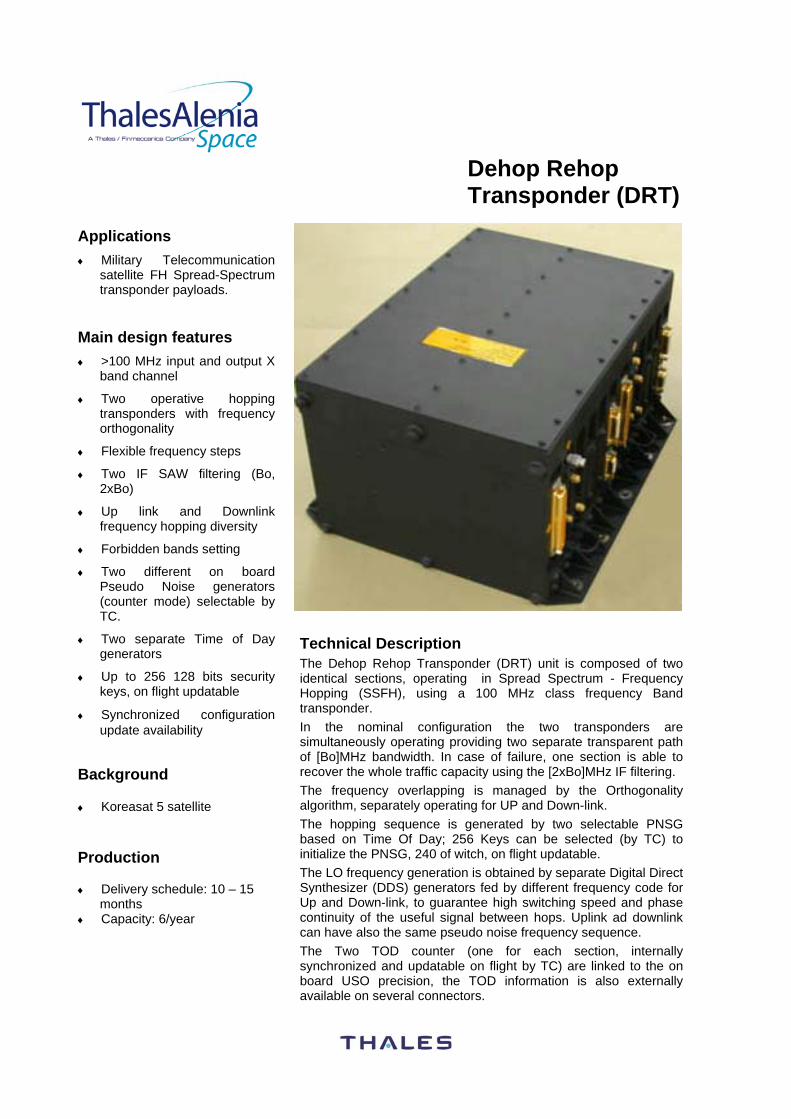
Dehop Rehop Transponder (DRT)
Applications ♦ Military Telecommunication
satellite FH Spread-Spectrum transponder payloads.
Main design features ♦ >100 MHz input and output X
band channel
♦ Two operative hopping transponders with frequency orthogonality
♦ Flexible frequency steps
♦ Two IF SAW filtering (Bo, 2xBo)
♦ Up link and Downlink frequency hopping diversity
♦ Forbidden bands setting
♦ Two different on board Pseudo Noise generators (counter mode) selectable by TC.
♦ Two separate Time of Day generators
♦ Up to 256 128 bits security keys, on flight updatable
♦ Synchronized configuration update availability
Background
♦ Koreasat 5 satellite
Production
♦ Delivery schedule: 10 – 15
months ♦ Capacity: 6/year
Technical Description The Dehop Rehop Transponder (DRT) unit is composed of two identical sections, operating in Spread Spectrum - Frequency Hopping (SSFH), using a 100 MHz class frequency Band transponder. In the nominal configuration the two transponders are simultaneously operating providing two separate transparent path of [Bo]MHz bandwidth. In case of failure, one section is able to recover the whole traffic capacity using the [2xBo]MHz IF filtering. The frequency overlapping is managed by the Orthogonality algorithm, separately operating for UP and Down-link. The hopping sequence is generated by two selectable PNSG based on Time Of Day; 256 Keys can be selected (by TC) to initialize the PNSG, 240 of witch, on flight updatable. The LO frequency generation is obtained by separate Digital Direct Synthesizer (DDS) generators fed by different frequency code for Up and Down-link, to guarantee high switching speed and phase continuity of the useful signal between hops. Uplink ad downlink can have also the same pseudo noise frequency sequence. The Two TOD counter (one for each section, internally synchronized and updatable on flight by TC) are linked to the on board USO precision, the TOD information is also externally available on several connectors.
For further information, please contact Thales Alenia Space Italy
Via Saccomuro, 24 00131 ROMA - ITALY Tel.: + 39(0)6 41511
Fax: + 39(0)6 4190675 Website : www.thalesaleniaspace.com
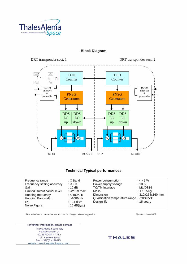
Block Diagram
TOD Counter
PNSG Generators
DDS LO up
DDS LO
down
TOD Counter
PNSG Generators
TC/TM interface
& µcontroller
TC/TM interface
& µcontroller
DDSLO up
DDS LO
down
RF IN RF IN RF OUT RF OUT
DRT transponder sect. 1 DRT transponder sect. 2
Technical Typical performances
Frequency range : X Band Frequency setting accuracy : <3Hz Gain : 10 dB Limited Output carrier level : -2dBm max Hopping frequency : ≤ 100KHz Hopping Bandwidth : >100MHz IP3 : +24 dBm Noise Figure : 15 dB(typ.)
Power consumption : < 45 W Power supply voltage : 100V TC/TM interface : ML/DS16 Mass : < 10.5Kg Dimension : 310x254x160 mm Qualification temperature range : -20/+65°C Design life : 15 years
This datasheet is not contractual and can be changed without any notice Updated : June 2012
Ka Band Transponder for Radio-Science
Applications High accuracy range and range-rate measurements for Radio-Science experiments. Main features The main features of the Ka-Band Transponder (KaT) for Radio-Science are summarized hereafter: ♦ Wide-band Regenerative PN Ranging up
to 25 Mcps ( MegaChipsPerSecond) ♦ On-board self-calibration function for
precise Group Delay measurement ♦ Excellent frequency stability
performances ♦ Additional Ranging modes capabilities: ♦ ESA/NASA Transparent Ranging
capabilities ♦ Mixed Ranging (transparent channel plus
Regenerated Tone up to 12.5 MHz) ♦ Flexible architecture and frequency plan ♦ Low power consumption ♦ Low weight and compact dimensions. ♦ Excellent performance stability over
temperature and lifetime Production ♦ Delivery schedule for EM: 14 months ♦ Delivery schedule for recurring FM: 18
months Background ♦ Cassini: fully analogue KaT ♦ Juno: 1 EM + 1 FM currently in flight
toward Jupiter ♦ MORE for BepiColombo: 1 EM + 1 EQM
+ 1 FM (under production)
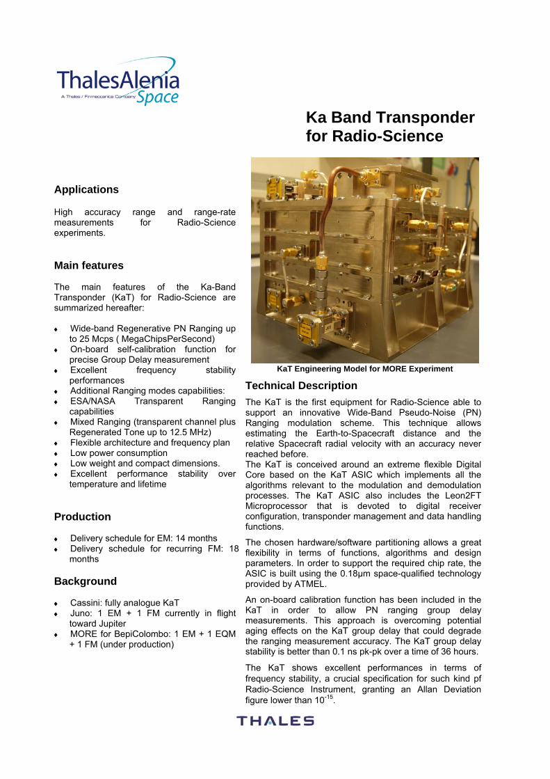
KaT Engineering Model for MORE Experiment
Technical Description
The KaT is the first equipment for Radio-Science able to support an innovative Wide-Band Pseudo-Noise (PN) Ranging modulation scheme. This technique allows estimating the Earth-to-Spacecraft distance and the relative Spacecraft radial velocity with an accuracy never reached before. The KaT is conceived around an extreme flexible Digital Core based on the KaT ASIC which implements all the algorithms relevant to the modulation and demodulation processes. The KaT ASIC also includes the Leon2FT Microprocessor that is devoted to digital receiver configuration, transponder management and data handling functions.
The chosen hardware/software partitioning allows a great flexibility in terms of functions, algorithms and design parameters. In order to support the required chip rate, the ASIC is built using the 0.18µm space-qualified technology provided by ATMEL.
An on-board calibration function has been included in the KaT in order to allow PN ranging group delay measurements. This approach is overcoming potential aging effects on the KaT group delay that could degrade the ranging measurement accuracy. The KaT group delay stability is better than 0.1 ns pk-pk over a time of 36 hours.
The KaT shows excellent performances in terms of frequency stability, a crucial specification for such kind pf Radio-Science Instrument, granting an Allan Deviation figure lower than 10-15.
For further information, please contact Thales Alenia Space Italy
Via Saccomuro, 24 00131 ROMA - ITALY Tel.: + 39(0)6 41511
Fax: + 39(0)6 4190675 Website : www.thalesaleniaspace.com
Technical Typical Performance
General Features Mass: ................................................................................................................................................................... 3 Kg Power consumption: .............................................................................................. < 40 W (for 32 dBm output power) Dimension (L x W x H): ......................................................................................…………..…….…..215x140x175 mm Power Bus Interface: ........................................................................................................................................ ≤100 V TM/TC Interface: .............................................................................................................ML/DS16, 1553, CAN, LSSB Qualification Status: ........................................................................................................................Under qualification Qualification temperature range: ............................................................................................... -20/+65°C (operative) Design life: ................................................................................................................................................... >15 Years
Performances Acquisition threshold : ................................................................................................................ -131 dBm @ 4 kHz/s Tracking threshold: ............................................................................ -135 dBm @ 1.2kHz/s (-138 dBm @ 400 Hz/s) Turn-around ratio: ........................................................................................................................................3360/3599 Output power: ........................................................................................................................Up to 35 dBm @ 32GHz Allan Deviation: ...........................................................................................................................≤4x10-16 @ 1000 sec Doppler shift:..................................................................................................................................................... ±6 MHz Noise figure:......................................................................................................................................................... <4 dB PN Ranging Chip rate:............................................................................................................................ up to 25 Mcps PN Ranging tracking jitter.................................................................................................<6 ns-rms @ Pr/N0=30dBHz Transparent Ranging BW: ............................................................................................................................... 27 MHz Mixed Ranging low-frequency BW: .................................................................................................................... 4 MHz KaT Group-delay stability: .......................................................................................................................<0.1ns pk-pk
This datasheet is not contractual and can be changed without any notice Updated : June 2012
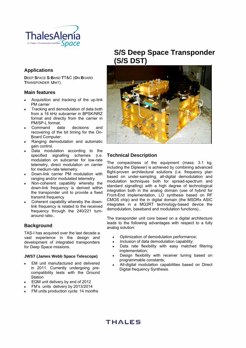
S/S Deep Space Transponder (S/S DST)
Applications DEEP SPACE S-BAND TT&C (ON BOARD TRANSPONDER UNIT). Main features ♦ Acquisition and tracking of the up-link
PM carrier ♦ Tracking and demodulation of data both
from a 16 kHz subcarrier in BPSK/NRZ format and directly from the carrier in PM/SP-L format.
♦ Command data decisions and recovering of the bit timing for the On-Board Computer.
♦ Ranging demodulation and automatic gain control.
♦ Data modulation according to the specified signalling schemes (i.e. modulation on subcarrier for low-rate telemetry, direct modulation on carrier for medium-rate telemetry.
♦ Down-link carrier PM modulation with ranging and/or modulated telemetry
♦ Non-coherent capability whereby the down-link frequency is derived within the transponder unit to provide a fixed transmit frequency
♦ Coherent capability whereby the down-link frequency is related to the received frequency through the 240/221 turn-around ratio..
Background TAS-I has acquired over the last decade a vast experience in the design and development of integrated transponders for Deep Space missions. JWST (James Webb Space Telescope)
♦ EM unit manufactured and delivered in 2011. Currently undergoing pre-compatibility tests with the Ground Station
♦ EQM unit delivery by end of 2012 ♦ FM’s units delivery by 2013/2014 ♦ FM units production cycle: 14 months
Technical Description
The compactness of the equipment (mass: 3.1 kg, including the Diplexer) is achieved by combining advanced flight-proven architectural solutions (i.e. frequency plan based on under-sampling, all-digital demodulation and modulation techniques both for spread-spectrum and standard signalling) with a high degree of technological integration both in the analog domain (use of hybrid for Front-End implementation, LO synthesis based on RF CMOS chip) and the in digital domain (the MSDRx ASIC integrates in a MG2RT technology-based device the demodulation, baseband and modulation functions).. The transponder unit core based on a digital architecture leads to the following advantages with respect to a fully analog solution:
♦ Optimization of demodulation performance; ♦ Inclusion of data demodulation capability; ♦ Data rate flexibility with easy matched filtering
implementation; ♦ Design flexibility with receiver tuning based on
programmable constants; ♦ All-digital modulation capabilities based on Direct
Digital frequency Synthesis.
For further information, please contact Thales Alenia Space Italy
Via Saccomuro, 24 00131 ROMA - ITALY Tel.: + 39(0)6 41511
Fax: + 39(0)6 4190675 Website : www.thalesaleniaspace.com
Main Characteristics
General Features Overall Frequency Stability ± 1 ppm (both for the receiver and transmitters sides) Telemetry and Telecommand Interface 1553, MLC/DS16
Receiver Side Nominal up-link carrier frequency Selectable in the S-Band TT&C range 2025-2120 MHz. In flight selection
of the up-link frequency by digital serial command. Modulation format PM/BPSK/NRZ, PM/SP-L, BPSK Receiver noise Figure < 2 dB Signal Dynamic Range From -60 dBm to -142 dBm Carrier Loop Bandwidth Tunable by firmware Tracking Range ±250 kHz at minimum carrier level Command Data rates PM/BPSK/NRZ:
− Selectable by command in range 7.8125 bps ÷ 4000 bps PM/SP-L: − Selectable by command in the range 16 kbps ÷ 256 kbps BPSK − Selectable by command up to 1 Mbps
Implementation loss < 2 dB Transmitter Side
Nominal down-link carrier frequency Selectable in the S-Band TT&C range 2200-2300 MHz. In flight selection of the up-link frequency by digital serial command.
Modulation format Residual Carrier: PM/BPSK/NRZ, PM/NRZ, PM/SP-L (up to 512 kbps) Suppressed Carrier: GMSK (up to 10 Mbps)
Modulation Indices Selectable by command, both for Telemetry and Ranging Transmitted Power Up to 6 W Spurious and Output harmonics Better than 50 dBc Coherent & Non-Coherent mode Selectable by command. In coherent mode the Rx/Tx turn-around ratio is
221/240 Integrated Phase Noise (10 Hz – 100 kHz) ≤ 2 deg-rms, Allan deviation at tracking threshold Integration Time = 100 s: <5×10-14
Power, Environment, Mass and Dimensions Power Input Voltage: 22 Volt - 35 Volt Consumption:
− Receiver: <13 W − Transmitter (6 W output): 30 W
Temperature Operating:-25°C to +60°C Non-Operating:-40°C to + 70°C Mass Budget < 3 kg (including diplexer) Dimensions 253 x 175 x 130 mm (LxWxH) overall
This datasheet is not contractual and can be changed without any notice Updated : June 2012
Spread-Spectrum Transponder Applications SPREAD SPECTRUM Transponder : ♦ Military and Civilian applications in
X/C//Ku/Ka band for secure Telemetry Tracking & Command systems
Main features ♦ Design Modularity: Implementation of
Receiver Front-End and transmitter Back- End in C/X/Ku/ka band
♦ Multi-standard Modulations: Direct Sequence Spread Spectrum (DS-SS), PM,FM
♦ Full Support of ESA/NASA Spreading Codes
♦ Support of Non Linear Spreading Codes with arbitrary length (support of AES in Counter Mode non linear Codes)
♦ Support of infinitely long PN Codes (Code period up to 50 years)
♦ Support of Advanced Aided Acquisition System for very Long PN Codes.
♦ Dual Mode DS-SS: ESA-NASA/AES Codes
♦ Up Link UQPSK demodulation capabilities
♦ Support of On-Board Viterbi decoding ♦ Command data rate flexibility (both on I
and Q channels) ♦ Different PN codes on I and Q
transmitter channels ♦ Full programmability of Up Link and
Down Link frequencies. ♦ Special Anti-jamming DSP: High Anti-
Jamming performance. ♦ Down Link I:Q power ratio flexibility ♦ Compact implementation
Background ♦ Koreasat 5: Equipment manufactured
and qualified. Currently on-orbit. ♦ Sicral 1b: Equipment manufactured
and qualified. Currently on-orbit. ♦ Yahsat 1A and 1B: Equipment
manufactured and qualified. Currently on-orbit.
♦ Sicral2 : Equipment manufacturing on-going.
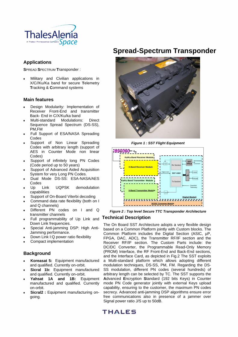
Figure 1 : SST Flight Equipment
Digital Module
Down-linkTelemetry
FRX
ADC
µPRAM
PROM
DC/DC Converter Module
SST ASIC
Rx Section
Tx Section
Demodulated
CommandSST
FPGA
DAC
Digital clock
Tx Analogue Module
Rx Analogue Module
X-Band Receiver Module
X-Band Transmitter Module
Ka/Ku-Band Receiver Module
Ka/Ku Band Transmitter Module
RF Input Filter
Figure 2 : Top level Secure TTC Transponder Architecture
Technical Description
The On Board SST Architecture adopts a very flexible design based on a Common Platform jointly with Custom blocks. The Common Platform includes the Digital Section (ASIC, µP, FPGA, DAC, ADC), the Transmitter RF/IF section and the Receiver RF/IF section. The Custom Parts include: the DC/DC Converter, the Programmable Read-Only Memory (PROM) Interface, the RF Front-End and Back-End sections, and the Interface Card, as depicted in Fig.2 The SST exploits a Multi-standard platform which allows adopting different modulation techniques, DS-SS, PM, FM. Regarding the DS-SS modulation, different PN codes (several hundreds) of arbitrary length can be selected by TC. The SST supports the Advanced Encryption Standard (192 bits Keys) in Counter mode PN Code generator jointly with external Keys upload capability, ensuring to the customer, the maximum PN codes secrecy. Advanced anti-jamming DSP algorithms ensure error free communications also in presence of a jammer over Signal power ratio J/S up to 50dB.
For further information, please contact Thales Alenia Space Italy
Via Saccomuro, 24 00131 ROMA - ITALY Tel.: + 39(0)6 41511
Fax: + 39(0)6 4190675 Website : www.thalesaleniaspace.com
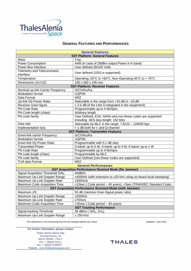
GENERAL FEATURES AND PERFORMANCES
General Features SST Platform: General Features
Mass 4 kg Power Consumption 44W (in case of 28dBm output Power in K band) Power Bus Interface User defined 28/100 Volts Telemetry and Telecommand Interface User defined (1553 is supported).
Temperature Operating:-25°C to +60°C ,Non-Operating-40°C to + 70°C Dimensions (XxYxZ) 150 x 282 x 195 mm
SST Platform: Receiver Features Nominal up-link Carrier Frequency S/C/X/Ku/Ka Modulation format UQPSK Data Format NRZ Up-link I/Q Power Ratio Selectable in the range from +10 dB to –10 dB Receiver noise figure < 2.5 dB (if the LNA is integrated in the equipment) PN Code Rate Programmable up to 4 Mchip/s. PN Code length (chips) Arbitrary length PN code family User Defined, ESA, NASA and non-linear codes are supported
including AES (key length: 192 bits) Data rate Selectable by MLC in the range: 7.8125 ÷ 128000 bps Implementation loss < 1 dB both for I- and Q-channel
SST Platform: Transmitter Features Down-link carrier Frequency S/C/X/Ku/Ka Modulation format UQPSK Down-link I/Q Power Ratio Programmable with 0.1 dB step Transmitted Power S-band: up to 5 W, X-band: up to 4 W, K-band: up to 1 W PN Code Rate Programmable up to 4 Mchip/s. PN code length (chips) Programmable by MLC PN code family User Defined (non-linear codes are supported) TLM data Format NRZ
General Performances SST Acquisition Performance Nominal Mode (No Jammer)
Signal Acquisition Threshold S/N0 40dBHz Maximum Up-Link Doppler Range ±4000Hz (with extension to ±20 kHz using on-board local sweeping) Maximum Up-Link Doppler Rate ±300Hz/s Maximum Code Acquisition Time <10sec ( Code period ~ 40 years), <3sec (TRANSEC Standard Code)
SST Acquisition Performance Stressed Mode (with Jammer) Maximum J/S 55 dB (Jammer-Over-Signal power ratio) Maximum Up-Link Doppler Range ±2500Hz Maximum Up-Link Doppler Rate ±70Hz/s Maximum Code Acquisition Time <25sec ( Code period ~ 40 years)
SST Tracking Performance Signal tracking Threshold 36 dBHz ( S/N0, S/J0) Maximum Up-Link Doppler Range ± 250 kHz
This datasheet is not contractual and can be changed without any notice Updated : June 2012
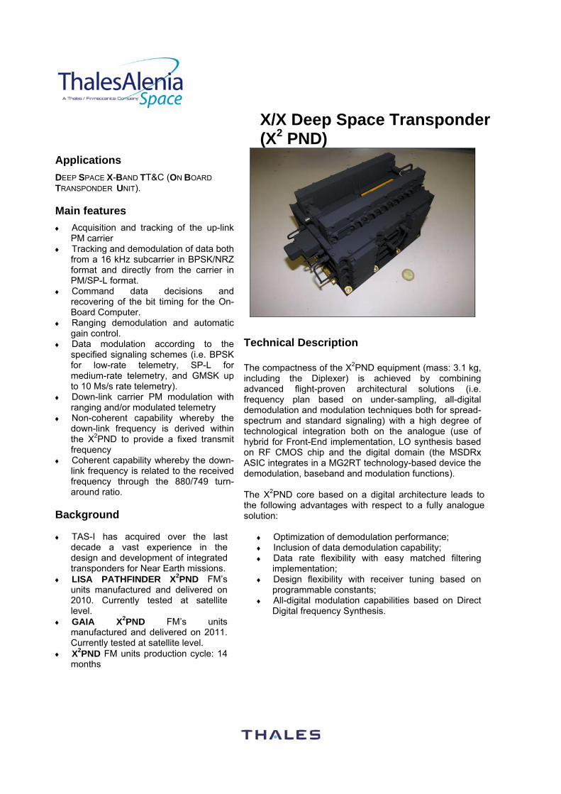
X/X Deep Space Transponder (X2 PND)
Applications DEEP SPACE X-BAND TT&C (ON BOARD TRANSPONDER UNIT). Main features ♦ Acquisition and tracking of the up-link
PM carrier ♦ Tracking and demodulation of data both
from a 16 kHz subcarrier in BPSK/NRZ format and directly from the carrier in PM/SP-L format.
♦ Command data decisions and recovering of the bit timing for the On-Board Computer.
♦ Ranging demodulation and automatic gain control.
♦ Data modulation according to the specified signaling schemes (i.e. BPSK for low-rate telemetry, SP-L for medium-rate telemetry, and GMSK up to 10 Ms/s rate telemetry).
♦ Down-link carrier PM modulation with ranging and/or modulated telemetry
♦ Non-coherent capability whereby the down-link frequency is derived within the X2PND to provide a fixed transmit frequency
♦ Coherent capability whereby the down-link frequency is related to the received frequency through the 880/749 turn-around ratio.
Background ♦ TAS-I has acquired over the last
decade a vast experience in the design and development of integrated transponders for Near Earth missions.
♦ LISA PATHFINDER X2PND FM’s units manufactured and delivered on 2010. Currently tested at satellite level.
♦ GAIA X2PND FM’s units manufactured and delivered on 2011. Currently tested at satellite level.
♦ X2PND FM units production cycle: 14 months
Technical Description The compactness of the X2PND equipment (mass: 3.1 kg, including the Diplexer) is achieved by combining advanced flight-proven architectural solutions (i.e. frequency plan based on under-sampling, all-digital demodulation and modulation techniques both for spread-spectrum and standard signaling) with a high degree of technological integration both on the analogue (use of hybrid for Front-End implementation, LO synthesis based on RF CMOS chip and the digital domain (the MSDRx ASIC integrates in a MG2RT technology-based device the demodulation, baseband and modulation functions). The X2PND core based on a digital architecture leads to the following advantages with respect to a fully analogue solution:
♦ Optimization of demodulation performance; ♦ Inclusion of data demodulation capability; ♦ Data rate flexibility with easy matched filtering
implementation; ♦ Design flexibility with receiver tuning based on
programmable constants; ♦ All-digital modulation capabilities based on Direct
Digital frequency Synthesis.
For further information, please contact Thales Alenia Space Italy
Via Saccomuro, 24 00131 ROMA - ITALY Tel.: + 39(0)6 41511
Fax: + 39(0)6 4190675 Website : www.thalesaleniaspace.com
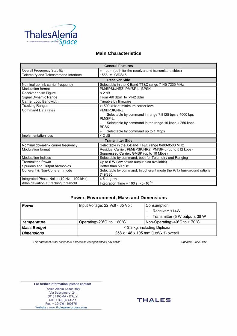
Main Characteristics
General Features
Overall Frequency Stability ± 1 ppm (both for the receiver and transmitters sides) Telemetry and Telecommand Interface 1553, MLC/DS16
Receiver Side Nominal up-link carrier frequency Selectable in the X-Band TT&C range 7145-7235 MHz Modulation format PM/BPSK/NRZ, PM/SP-L, BPSK Receiver noise Figure < 2 dB Signal Dynamic Range From -60 dBm to -142 dBm Carrier Loop Bandwidth Tunable by firmware Tracking Range >±500 kHz at minimum carrier level Command Data rates PM/BPSK/NRZ:
− Selectable by command in range 7.8125 bps ÷ 4000 bps PM/SP-L: − Selectable by command in the range 16 kbps ÷ 256 kbps BPSK − Selectable by command up to 1 Mbps
Implementation loss < 2 dB Transmitter Side
Nominal down-link carrier frequency Selectable in the X-Band TT&C range 8400-8500 MHz Modulation format Residual Carrier: PM/BPSK/NRZ, PM/SP-L (up to 512 kbps)
Suppressed Carrier: GMSK (up to 10 Mbps) Modulation Indices Selectable by command, both for Telemetry and Ranging Transmitted Power Up to 6 W (low power output also available) Spurious and Output harmonics Better than 50 dBc Coherent & Non-Coherent mode Selectable by command. In coherent mode the R/Tx turn-around ratio is
749/880 Integrated Phase Noise (10 Hz – 100 kHz) ≤ 5 deg-rms, Allan deviation at tracking threshold Integration Time = 100 s: <5×10-14
Power, Environment, Mass and Dimensions Power Input Voltage: 22 Volt - 35 Volt Consumption:
− Receiver: <14W − Transmitter (5 W output): 38 W
Temperature Operating:-20°C to +60°C Non-Operating:-40°C to + 70°C Mass Budget < 3.3 kg, including Diplexer Dimensions 258 x 148 x 195 mm (LxWxH) overall
This datasheet is not contractual and can be changed without any notice Updated : June 2012
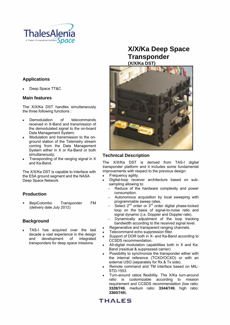
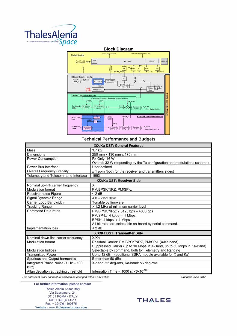
X/X/Ka Deep Space Transponder (X/X/Ka DST)
Applications ♦ Deep Space TT&C Main features The X/X/Ka DST handles simultaneously the three following functions : ♦ Demodulation of telecommands
received in X-Band and transmission of the demodulated signal to the on-board Data Management System;
♦ Modulation and transmission to the on-ground station of the Telemetry stream coming from the Data Management System either in X or Ka-Band or both simultaneously;
♦ Transponding of the ranging signal in X and Ka-Band.
The X/X/Ka DST is capable to interface with the ESA ground segment and the NASA Deep Space Network. Production BepiColombo Transponder FM
(delivery date July 2012) Background ♦ TAS-I has acquired over the last
decade a vast experience in the design and development of integrated transponders for deep space missions.
Technical Description
The X/X/Ka DST is derived from TAS-I digital transponder platform and it includes some fundamental improvements with respect to the previous design: ♦ Frequency agility. ♦ Digital-loop receiver architecture based on sub-
sampling allowing to: – Reduce of the hardware complexity and power
consumption. – Autonomous acquisition by local sweeping with
programmable sweep rates. – Select 2nd order or 3rd order digital phase-locked
loop on the basis of signal-to-noise ratio and signal dynamic (i.e. Doppler and Doppler rate).
– Dynamically adjustment of the loop tracking bandwidth according to the received signal level.
♦ Regenerative and transparent ranging channels. ♦ Telecommand echo suppression filter. ♦ Support of DOR both in X- and Ka-Band according to
CCSDS recommendation. ♦ All-digital modulation capabilities both in X and Ka-
Band (residual & suppressed carrier) ♦ Possibility to synchronize the transponder either with
the internal reference (TCXO/OCXO) or with an external USO (separately for Rx & Tx side).
♦ Remote command and TM interface based on MIL-STD-1553.
♦ Turn-around ratios flexibility. The X/Ka turn-around ratio is customizable according to mission requirement and CCSDS recommendation (low ratio: 3328/749, medium ratio: 3344/749, high ratio: 3360/749).
For further information, please contact Thales Alenia Space Italy
Via Saccomuro, 24 00131 ROMA - ITALY Tel.: + 39(0)6 41511
Fax: + 39(0)6 4190675 Website : www.thalesaleniaspace.com
Block Diagram
1st IF Section(15F1+Fd)
Integer-N PLLOCXOCard
From X-band Diplexer(749 F1+Fd)
SAW
X-Tx Section Frequency Generation (Integer-N PLL’s)
To X-band SSPA
2nd IF Section(110F1)
77F1
Tx Front-End(880F1)
770F1
1st IF Section(33F1)
To Ka-band TWTA
2nd IF Section(264F1)
231F1
Tx Front-End(3344F1)
3080F1
734F1
8F1
X-Band Receiver Module
X-Band Transmitter Module
Ka-Band Transmitter Module
DC
/DC
Converter M
odule
Digital Module
AGC
Con
trol
Dig
ital C
lock
X3
X4
From Digital Module
Baseband Section From Digital Module
4F1
PM Modulator
2nd IF Section(39/4 F1)
(21/8)F1+Fd/2
(39/4) F1
Baseband Section
ADCDAC DAC DAC
DST ASIC
To X-Tx To Ka-Tx
Demodulated Command Down-link Telemetry (data & clock)
1553 RT
From/To 1553Bus Controller
F1+F1/2
LEON µP Memories
Rx Front-End
From OCXO Card
DOR Tone(to Ka-Tx)
x2
F1+F1/2
31F1+F1/2
31F1+F1/2
3F1 PLL
6F1
Comp. @ F1/2
Technical Performance and Budgets
X/X/Ka DST: General Features Mass 3.7 kg Dimensions 250 mm x 130 mm x 175 mm Power Consumption Rx Only: 16 W
Overall: 32 W (depending by the Tx configuration and modulations scheme) Power Bus Interface User defined Overall Frequency Stability ± 1 ppm (both for the receiver and transmitters sides) Telemetry and Telecommand Interface 1553
X/X/Ka DST: Receiver Side Nominal up-link carrier frequency X Modulation format PM/BPSK/NRZ, PM/SP-L Receiver noise Figure < 2 dB Signal Dynamic Range -60 ÷ -151 dBm Carrier Loop Bandwidth Tunable by firmware Tracking Range > 1.2 MHz at minimum carrier level Command Data rates PM/BPSK/NRZ: 7.8125 bps ÷ 4000 bps
PM/SP-L: 4 kbps ÷ 1 Mbps BPSK: 4 kbps ÷ 4 Mbps All bit rates are selectable on-board by serial command.
Implementation loss < 2 dB X/X/Ka DST: Transmitter Side
Nominal down-link carrier frequency X/Ka Modulation format Residual Carrier: PM/BPSK/NRZ, PM/SP-L (X/Ka band)
Suppressed Carrier (up to 10 Mbps in X-Band, up to 50 Mbps in Ka-Band) Modulation Indices Selectable by command, both for Telemetry and Ranging Transmitted Power Up to 12 dBm (additional SSPA module available for X and Ka) Spurious and Output harmonics Better than 50 dBc Integrated Phase Noise (1 Hz – 100 kHz)
X-band: ≤2 deg-rms, Ka-band: ≤6 deg-rms
Allan deviation at tracking threshold Integration Time = 1000 s: <6x10-16 This datasheet is not contractual and can be changed without any notice Updated: June 2012