deep foundatio
DESCRIPTION
Deep FoundationTRANSCRIPT

Deep Foundation

1. Deep Foundations are those in which the depth of the foundation is
very large in comparison to its width. Which are not constructed by ordinary
methods of open pit excavations.

In cases where The strata of good bearing capacity is not available
near the ground The space is restricted to allow for spread footings
In these cases the foundation of the structure has to be taken deep with the purpose of attaining a bearing stratum which is suitable and which ensures stability and durability of a structure.
The bearing stratum is not the only case. There may be many other cases. For example, the foundation for a bridge pier must be placed below the scour depth, although suitable bearing stratum may exist at a higher level.
Most common forms of construction pertaining to deep foundations are:
Pile Foundation (more commonly used in building construction)
Cofferdams
Caisson or Well Foundation

The term ‘Pile Foundation’ denotes a construction for the foundation of a wall or pier which is supported on piles.
Where Used : stratum of required bearing capacity is at greater depth steep slopes are encountered Compressible soil or water-logged soil or soil of made-up
type
Examples: Piles are used for foundation for buildings, trestle-bridges and water front installations (piers, docks etc ).
Advantages: Provides a common solution to all difficult foundation site
problems Can be used for any type of structure and in any type of
soil

Situations Which Demand Pile Foundation : Sub-soil water table is so high that it can easily affect the other
foundations. Load coming form the structure is heavy and non uniform. Where grillage or raft foundations are either very costly or their
adoption impossible due to local difficulties. When it is not possible to maintain foundation trenches in dry condition
by pumping, due to very heavy inflow of seepage or capillary water. When it is not possible to timber the excavation trenches in the case of
deep strip foundation. (strip foundation- spread footing under wall ). When overlay soil is compressible, and water-logged and firm hard
bearing strata is located at quite a large depth. When structures are located on river-bed or sea-shore and foundations
are likely to be scoured due to action of water. Large fluctuations in sub-soil water level. Canal or deep drainage lines exist near the foundations. In the construction of docks, piers and other marine structures they are
used as fender piles.

a) Classification based on Function or Use1. Bearing Piles or End Bearing Piles2. Friction Piles or Skin Friction Piles3. Sheet Piles4. Tension Piles or Uplift Piles5. Anchor Piles6. Batter Piles7. Fender Piles8. Compaction Piles
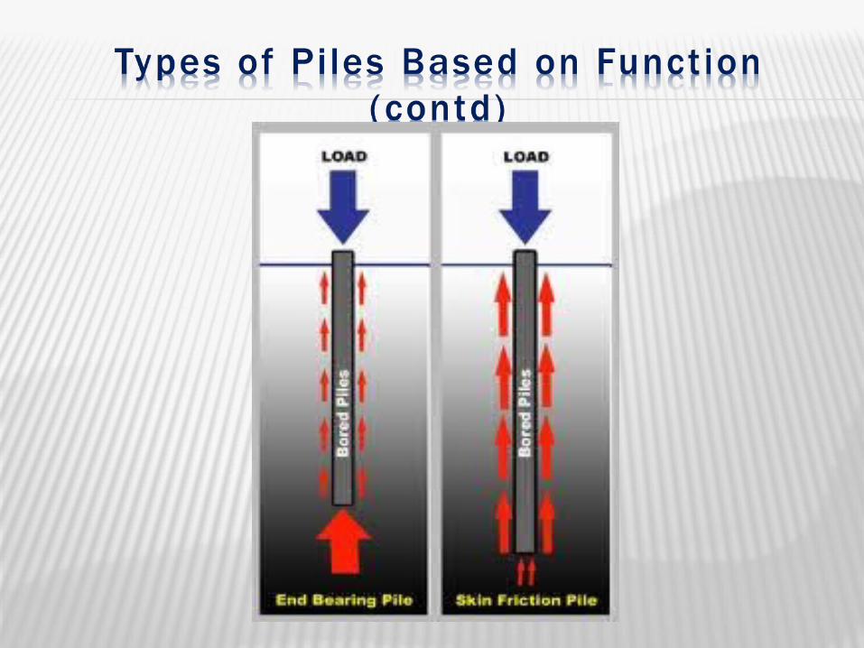
Bearing Piles
Driven into the ground until a hard stratum is
reached.
Acts as pillars supporting the super-structure and
transmitting the load to the ground.
Piles, by themselves do not support the load, rather
acts as a medium to transmit the load from the
foundation to the resisting sub-stratum.

Friction Piles (Floating Piles) Piles are driven at a site where soil is weak or soft to a
considerable depth and it is not economical or rather possible to rest the bottom end of the pile on the hard stratum,
Load is carried by the friction developed between the sides of the pile and the surrounding ground ( skin friction).
The piles are driven up to such a depth that skin friction developed at the sides of the piles equals the load coming on the piles.
Skin friction should be carefully evaluated and suitable factor of safety applied, as it is this which is supporting the whole of structure over its head.
The load carrying capacity of friction pile can be increased by- increasing diameter of the pile driving the pile for larger depth grouping of piles making surface of the pile rough


Sheet Piles Sheet piles are never used to provide vertical
support but mostly used to act as retaining walls. They are used for the following purposes:
To construct retaining walls in docks, and other marine works.
To protect erosion of river banks. To retain the sides of foundation trenches. To confine the soil to increase its bearing capacity. To protect the foundation of structures from erosion by
river or sea. To isolate foundations from adjacent soils.

Figure: Sheet Piles
Anchor Piles Piles are used to provide anchorage against horizontal pull from
sheet piling wall or other pulling forces.
Batter piles: Piles are driven at an inclination to resist large horizontal and
inclined forces.
Fender piles: Piles are used to protect concrete deck or other water front
structures from the abrasion or impact caused from the ships or barges.
Ordinarily made up of timber.
Compaction piles: When piles are driven in granular soil with the aim of increasing
the bearing capacity of the soil, the piles are termed as compaction piles.
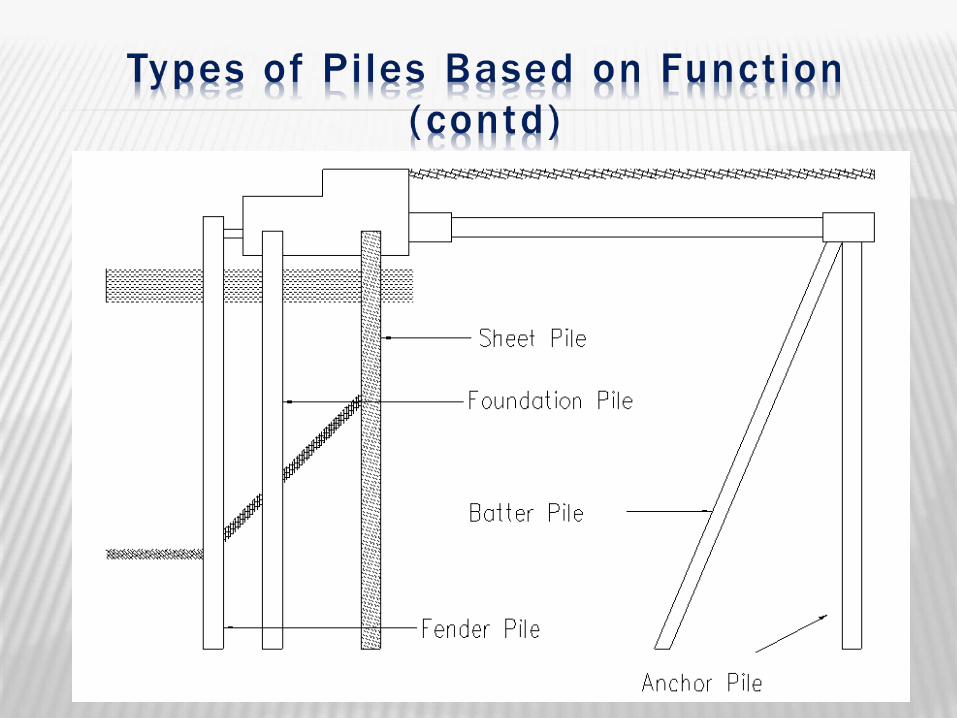

Figure: Under-reamed Piles

a) Classification based on Materials
1. Timber Piles
2. Concrete Piles
3. Composite Piles
4. Steel Piles
5. Sand Piles

1. Timber Piles: Transmission of load takes place by the frictional
resistance of ground and the pile surface. Economical to support light structure. Piles made from timber of tree like Sal, Teak, Deodar,
Babul, Khair etc. Khair piles can stand action of sea water and thus used
for marine works. May be circular, square in x-section. Piles are driven with the help of pile driving machine in
which drop hammers delivers blows on the pile head. Brooming of pile head is prevented by providing an iron
ring of less than 25mm in diameter than the pile head at the pile top.
1. Timber Piles: To facilitate driving, the lower end is pointed and provided with a
cast iron conical shoe. Piles should not be spaced less than 60 cm center to center, the
best spacing is 90 cm c/c. closer spacing destroys frictional resistance.
Max load should not exceed 20 tonnes. Piles are subjected to decay for alternate dry and wet condition
(on account of variation of ground water level) As such , timber piles are cut a little below the lowest water-mark
and capped with concrete, steel grillage, stone or timber. If timber capping is used, the cap should be permanently under
water. Diameter varies from 30 to 50cm. Length should not be more than 20 times the least sectional
dimension.
Advantages of Timber Piles: Economical where timber is easily available. Can be driven rapidly & as such saves time. Because of elasticity, timber piles are recommended for
sites subjected to unusual lateral forces e.g. ship, ferry terminals.
Do not need heavy machinery and elaborate technical supervision.
Being light, they can be easily handled. They can be easily withdrawn if needed.

Disadvantages of Timber Piles: Timber piles must be cut off below the permanent ground
water level to prevent decay. Liable to decay or deteriorate by salt water/insects. Restricted length. It is rather difficult to procure piles in
required size and length. Low bearing capacity. They are not very durable unless suitably treated. It is difficult or rather impossible to drive these piles into
hard stratum
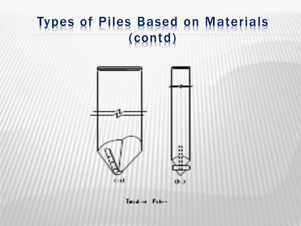

Figure: Timber Pile

Concrete Piles are of 3 types: Pre-cast Piles Cast in situ Piles Prestressed Concrete Piles
Pre-cast Piles: Reinforced concrete piles, molded in circular,
square, rectangular or octagonal form. Cast and cured in the casting yard, then
transported to the site of driving. If space available it can be cast and cured near the
work site. Driven in similar manner as timber piles with the
help of piles drivers. Diameter normally varies from 35cm to 65cm,
length varies from 4.5m to 30m.

Pre-cast Piles: Function of reinforcement in a pre-cast pile is to
resist the stresses during handling, driving and final loading on the pile rather than strengthen the pile to act as a column.
Longitudinal reinforcements usually 20mm to 50mm in diameter, stirrups 6mm to 10mm in dia.
For 90 cm length at head and toe, stirrups spacing is 8cm c/c and for remaining intermediate length it is about 30cm c/c.
Circular piles are seldom tapered. When tapered piles length is restricted to 12m.
A concrete cover of 5cm is maintained throughout, over the main steel bars.

Advantages of Pre-cast Piles: Very effective Simple quality control Improves the entire area
Disadvantages of Pre-cast Piles: Limited in length Difficult to transport Not suitable for densely built up area Requires costly equipment


Cast-in-Situ Piles: Cast in position inside the ground. First of all a bore is dug by driving a casing pipe
into the ground. Then the soil from the casing is jetted out and filled
with cement concrete after placing necessary reinforcement in it.
Cast-in-situ piles are of two types: I. Cased Cast-in-Situ Piles: metallic shell is left
inside the ground along with the coreII. Uncased Cast-in-Situ Piles: metallic shell is
withdrawn
Advantages of Cast-in-Situ Concrete Piles: Not limited in length Can be cast at any place Requires less equipment Cost is less and is depended on the size
Disadvantages of Cast-in-Situ Concrete Piles: Quality control is difficult Load carrying is mostly done through end bearing
only Skin frictional resistance is very low.

Figure: Cast-in-Situ Pile

Advantages of Concrete piles: Durability is independent of ground water level. For large size and greater bearing power number of
piles required is much less. Can be cast to any length, size or shape. Can be used to marine work without any treatment. Material required for manufacture is easily
obtainable. Concrete piles can be monolithically bonded into
pile cap which is not possible in wooden piles.

Disadvantages of Concrete piles: Costlier than timber piles. Can not be driven rapidly. Required elaborate tech supervision and heavy
driving machines. Must be reinforced to withstand handling stresses.
Prestressed Concrete Piles The greatest disadvantage of large weightt and
difficulty in handling of pre-cast pile is eliminated by prestressed concrete piles.
The weight is reduced by casting 200mm to 300mm diameter fiber tubes inside the piles at the time of concreting.
The pre tensioning cables are subjected to required pull (tension) in the casting bed.
The fiber tube is held in position inside the form work and the piles reinforced with pre stressed cables are concreted in a row.

Prestressed Concrete Piles Prestressed concrete piles are provided with lifting
hooks at 1/5th ( 0.2L, L= length of pile ) of pile length from each end.
Piles length 50 times the thickness →single point pick up
More than 50 times the thickness →two point pick up at 0.2L from either end.
Piles 500 sq. mm and smaller→ cast solid. Piles over 500 sq. mm may be cast with 200mm to
300mm cored hole (void). Pre stressed piles are always pre- cast.
Advantages of Prestressed Concrete Piles It has greater ability to withstand extremely hard
driving. It is more durable in sea water because of absence
of crack. It has greater column capacity. It has lesser handling costs because of light weight. It requires lesser pick-up points. It has larger moment of inertia than the
conventional piles of same dimension since the concrete is all in compression.

Piles of two different materials are driven one over the other, so as to enable them to act together to perform the function of a single pile.
This type of composite pile is used with the object of achieving economy in the cost of piling work.


The nature of the ground, where piling operation is to be carried out, determines to a large extent the choice of type of pile to be used.
In addition, the other important factors which must be considered in this regard are:
The nature of the structure. Loading conditions. Elevation of the ground water level with respect to
the pile cap. Probable length of pile required. Availability of materials and equipment. Factors which may cause deterioration of pile. Probable cost of pile.

Load on the pile is more than the designed load. Defective workmanship during casting of the pile. Displacement of reinforcement during casting. Bearing pile resting on a soft strata. Improper classification of soil. Improper choice of the type of pile. Insufficient reinforcement in the pile. Decay of timber piles due to attack by insects. Buckling of piles due to inadequate lateral support. Defective method adopted for driving the pile. Incorrect assessment of the bearing capacity of the
pile. Lateral forces not considered in the design of piles.

I. By Drop Hammer.II. By Steam Hammer.III. By Water Jets (Wash Boring ).IV. By Boring (Auger Boring).

Hammer is raised by a rope or a steel cable
Then it is allowed to drop on pile cap The weight of drop varies from 230-
1800 kg Weight depends on the shape and
length of pile and the nature of the ground
Takes a lot of time
Hammer is automatically raised and dropped.
A steam cylinder and piston is used. Steam pressure and the rate of
hammer blow are kept uniform. Steam Hammers are of two types
Single Acting Type Double Acting Type

Wash boring is a fast and simple method for advancing holes in soft to stiff cohesive soils and fine sand. Boulders and rock can not be penetrated by this method.
The method consists of first driving a hollow steel pipe known as casing pipe/drive pipe in to the ground.
Through this casing pipe, a hollow drilled rod with a sharp chisel or chopping bit at the lower end known as water jet pipe or wash pipe is inserted.
Upper end of wash pipe is connected to water pump and lower end is contracted to produce get action.

Water is forced under pressure through the drill rod which is alternatively raised and dropped, and also rotated. The resulting chopping and getting action of the bit and water disintegrates the soil.
The cuttings are forced up to the ground surface in the form of soil-water slurry through the annular space between the drill rod and the casing.
The slurry is collected and samples of materials are obtained by settlement.

Interpretation of Results The change in soil stratification is guessed from the rate of
progress of driving the casing pipe and from the color of slurry flowing out.
Results give fairly good information about the nature of the sub-soil strata.
Disadvantages Finer particles such as clay, loam etc do not settle easily. Larger and heavy particles may not be brought up at all. Exact location of materials can not be easily determined.
Can penetrate beds of hard soil or soft rock Augur or Rotary Drilling can be used. Precast and In-situ piles may be used.

Cofferdams may be defined as a temporary structure constructed in a river or a lake or any other water bearing surface for excluding water form a given site to enable the building operation to be performed on dry surface.
Cofferdams may be divided into the following category based on the materials used during construction:
Earthier cofferdam. Rock fill cofferdam. Single-walled cofferdam. Double-walled cofferdam. Crib V Cellular cofferdam.(Circular or diaphragm type)

Caissons are water light structures made up of wood, steel or reinforced concrete, constructed in connection with excavation for foundations of bridges, piers, abutments in river and lake dock structure fore shore protection etc.
The caisson remains in its pose and ultimately becomes as integral parts of the permanent structure.
Caisson can be broadly classified into the following three types:
Open Caisson Box Caisson (Floating Caisson) Pneumatic Caisson