deep drawing of cup
TRANSCRIPT

7/26/2019 Deep Drawing of Cup
http://slidepdf.com/reader/full/deep-drawing-of-cup 1/54
PATRAN 322 Exercise Workbook A6-1
APPENDIX 6
Deep Drawing of a
Cylindrical Cup
X
Y
Z
Objectives:
Large displacement analysis.
Contact analysis.
Plasticity theory.

7/26/2019 Deep Drawing of Cup
http://slidepdf.com/reader/full/deep-drawing-of-cup 2/54
A6-2 PATRAN 322 Exercise Workbook
7/26/2019 Deep Drawing of Cup
http://slidepdf.com/reader/full/deep-drawing-of-cup 3/54
APPENDIX 6 Deep Drawing of a Cylindrical Cup
PATRAN 322 Exercise Workbook A6-3
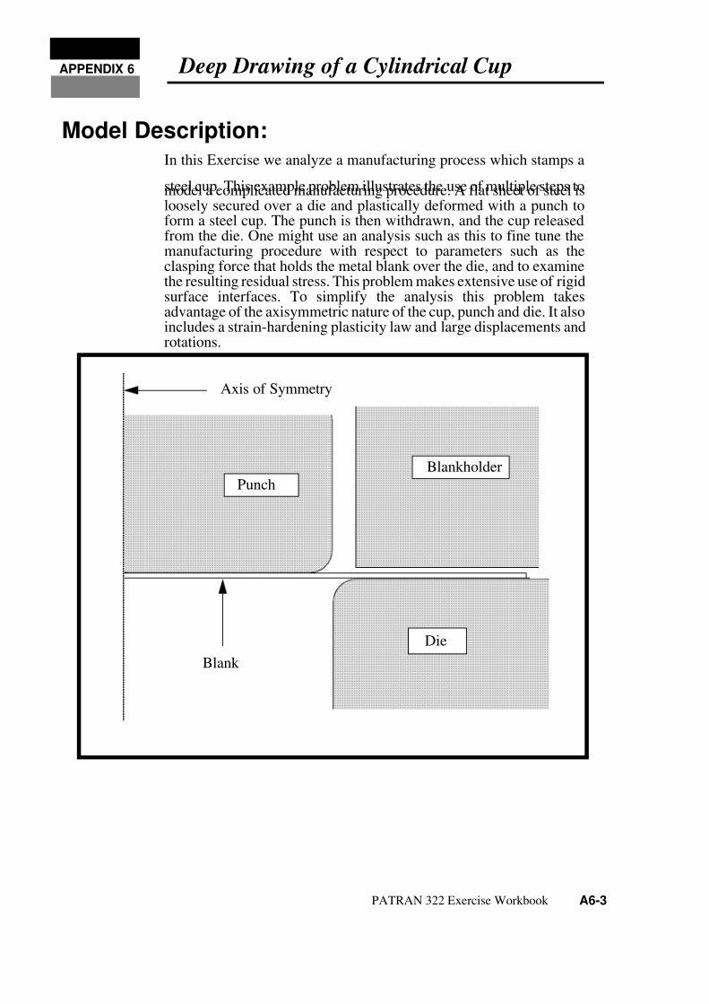
Model Description:In this Exercise we analyze a manufacturing process which stamps a
steel cup. This example problem illustrates the use of multiple steps tomodel a complicated manufacturing procedure. A flat sheet of steel isloosely secured over a die and plastically deformed with a punch toform a steel cup. The punch is then withdrawn, and the cup releasedfrom the die. One might use an analysis such as this to fine tune themanufacturing procedure with respect to parameters such as theclasping force that holds the metal blank over the die, and to examinethe resulting residual stress. This problem makes extensive use of rigidsurface interfaces. To simplify the analysis this problem takesadvantage of the axisymmetric nature of the cup, punch and die. It alsoincludes a strain-hardening plasticity law and large displacements androtations.
Axis of Symmetry
Punch
Blankholder
Die
Blank
7/26/2019 Deep Drawing of Cup
http://slidepdf.com/reader/full/deep-drawing-of-cup 4/54
A6-4 PATRAN 322 Exercise Workbook
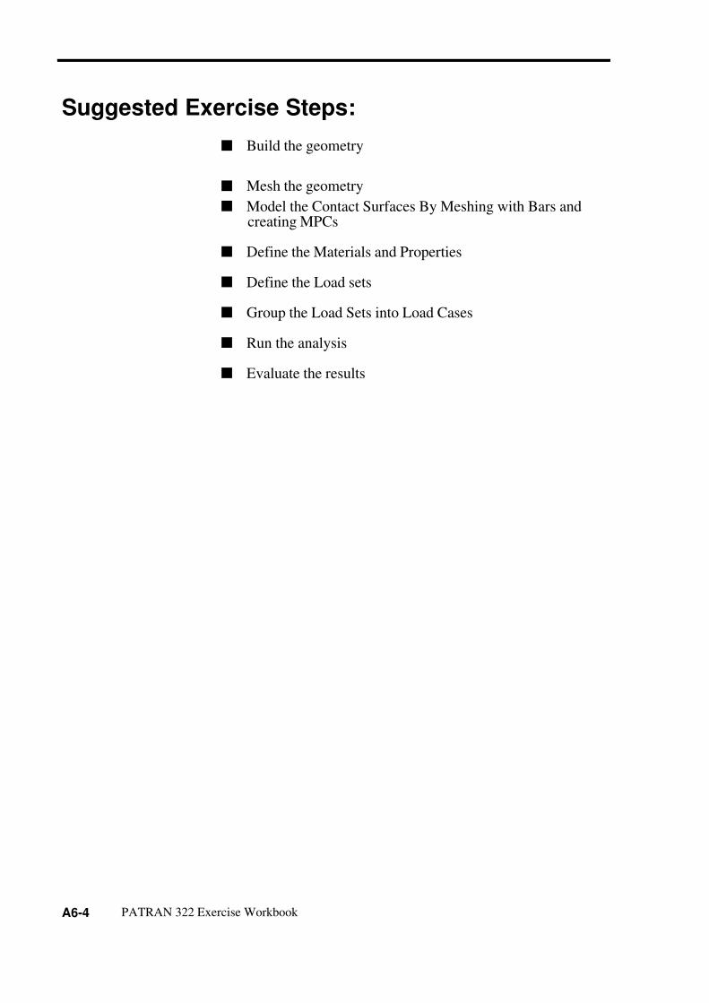
Suggested Exercise Steps:
Build the geometry
Mesh the geometry
Model the Contact Surfaces By Meshing with Bars andcreating MPCs
Define the Materials and Properties
Define the Load sets
Group the Load Sets into Load Cases
Run the analysis
Evaluate the results

7/26/2019 Deep Drawing of Cup
http://slidepdf.com/reader/full/deep-drawing-of-cup 5/54
APPENDIX 6 Deep Drawing of a Cylindrical Cup
PATRAN 322 Exercise Workbook A6-5
Exercise Procedure:1. Open a new database called cup.db.
Change the Analysis Preference to MSC ⁄ ADVANCEDFEA.
2. Create the geometry for the blank
First, create a Group called blank.
3. Increase the point size to make viewing easier.
File/New ...
Database Name: cup.db
OK
Analysis Code: MSC/ADVANCED_FEA
OK
Group/Create...
New Group Name: blank
Make Current
Group Contents: Add Entity Selection
Apply
Cancel
Geometry
Action: Create
Object: Surface
Method: XYZ
Vector Coordinates List: <4, .0325, 0>
Origin: [0, 0, 0]
Apply

7/26/2019 Deep Drawing of Cup
http://slidepdf.com/reader/full/deep-drawing-of-cup 6/54
A6-6 PATRAN 322 Exercise Workbook
Increase the point size by selecting the following icon.
4. Create the Finite Element Mesh for the blank.
5. Model the die rigid surface elements.
In this step, you are going to coat the bottom surface of the blank withbar elements. Later you are going to assign IRS element properties tothese elements. These IRS elements correspond to the die rigid surfaceto be created later.
Create a new group called die and make it current so all the newlycreated entities will be contained in this group.
6. Create the reference node and rigid surface for the die.
Finite Elements
Action: Create
Object: Mesh
Type: Surface
Global Edge Length: 0.1
Element Topology: Quad4
Surface List: Surface 1
Apply
Group/Create...
New Group Name: die
Make Current
Group Contents: Add Entity Selection
Apply
Cancel
Geometry
Action: Create
Object: Point
Point Size

7/26/2019 Deep Drawing of Cup
http://slidepdf.com/reader/full/deep-drawing-of-cup 7/54
APPENDIX 6 Deep Drawing of a Cylindrical Cup
PATRAN 322 Exercise Workbook A6-7
This creates Point 5
7. Create the geometry for the die rigid surface.
This creates Curve 1.
Repeat the procedure with these changes
Method: XYZ
Point Coordinates List: [4, -2, 0]
Apply
Action: Create
Object: Curve
Method: XYZ
Vector Coordinates List: <0, -4, 0>
Origin Coordinates List: [2.05, -0.1, 0]
Apply
Vector Coordinates List: <4, 0, 0>Origin Coordinates List: [2.05, -0.1, 0]
Apply
7/26/2019 Deep Drawing of Cup
http://slidepdf.com/reader/full/deep-drawing-of-cup 8/54
A6-8 PATRAN 322 Exercise Workbook
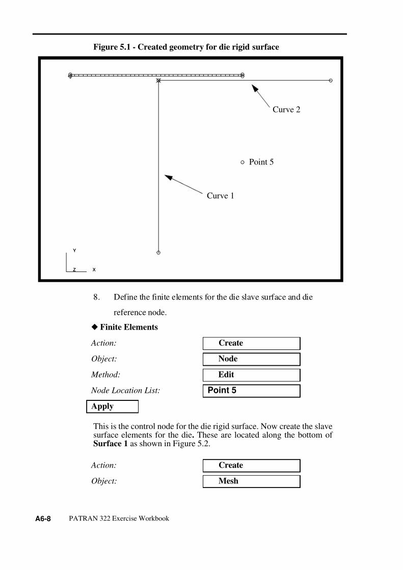
Figure 5.1 - Created geometry for die rigid surface
8. Define the finite elements for the die slave surface and die
reference node.
This is the control node for the die rigid surface. Now create the slavesurface elements for the die. These are located along the bottom of Surface 1 as shown in Figure 5.2.
Finite Elements
Action: Create
Object: Node
Method: Edit
Node Location List: Point 5
Apply
Action: Create
Object: Mesh
Curve 1
Curve 2
X
Y
Z X
Y
Z
Point 5

7/26/2019 Deep Drawing of Cup
http://slidepdf.com/reader/full/deep-drawing-of-cup 9/54
APPENDIX 6 Deep Drawing of a Cylindrical Cup
PATRAN 322 Exercise Workbook A6-9
Select the lower edge of the blank, Surface 1.4
Figure 5.2 - Blank edge to contact die surface.
Duplicate nodes are created when the Bar2 elements are created on theedge of the surface. You will use equivalencing in a later step toremove all duplicate nodes.
9. Create the finite elements for the die rigid surface.
Type: Curve
Global Edge Length: 0.1
Curve List: Surface 1.4
Apply
Finite Elements
Action: Create
Object: MeshType: Curve
Global Edge Length: 4
Curve List: Curve 1, 2
Select this edge for meshing

7/26/2019 Deep Drawing of Cup
http://slidepdf.com/reader/full/deep-drawing-of-cup 10/54
A6-10 PATRAN 322 Exercise Workbook
Figure 5.3 - Geometry to create die surface elements upon
10. Create the punch rigid surface elements.
In this step, you are going to coat the top surface of the blank with barelements again. Later you are going to assign IRS element propertiesto these elements. These IRS elements will correspond to the punchrigid surface to be created later.
Apply
Group/Create...
New Group Name: punch
Make Current
Group Contents: Add Entity Selection
Apply
Cancel
Curve 1
Curve 2
X
Y
Z X
Y
Z
Point 5

7/26/2019 Deep Drawing of Cup
http://slidepdf.com/reader/full/deep-drawing-of-cup 11/54
APPENDIX 6 Deep Drawing of a Cylindrical Cup
PATRAN 322 Exercise Workbook A6-11
11. Create the geometry for the punch reference node andrigid body.
This results in Point 9.
12. Create the geometry for the punch rigid surface.
This creates Curve 3
Repeat the procedure with these changes
This creates Curve 4.
Geometry
Action: Create
Object: Point
Method: XYZ
Point Coordinates List: [0, 2, 0]
Apply
Action: Create
Object: Curve
Method: XYZ
Vector Coordinates List: <0, 4, 0>
Origin Coordinates List: [2.0, 0.1325, 0]
Apply
Vector Coordinates List: <-2, 0, 0>
Origin Coordinates List: [2, 0.1325, 0]
Apply

7/26/2019 Deep Drawing of Cup
http://slidepdf.com/reader/full/deep-drawing-of-cup 12/54
A6-12 PATRAN 322 Exercise Workbook
Figure 5.4 - Created geometry for punch rigid surface
13. Mesh the top edge of surface 1 with bar2 elements to
define the slave contact surface for the punch.
Finite Elements
Action: Create
Object: Mesh
Type: Curve
Global Edge Length: 0.1
Curve List: Curve 7, 8
Apply
Curve 3
Curve 4
Point 9
X
Y
Z X
Y
Z

7/26/2019 Deep Drawing of Cup
http://slidepdf.com/reader/full/deep-drawing-of-cup 13/54
APPENDIX 6 Deep Drawing of a Cylindrical Cup
PATRAN 322 Exercise Workbook A6-13
Figure 5.5 - Blank edge to contact punch surface
14. Create the finite elements for the punch rigid surface andreference node.
This is the control node for the punch rigid surface.
15. Create the holder interface rigid surface (IRS) elements
Action: Create
Object: Mesh
Type: Curve
Global Edge Length: 4
Element Topology: Bar2
Curve List: Curve 3 4
Apply
Action: Create
Object: Node
Method: Edit
Node Location List: Point 9
Apply
Select top edge for meshing
(Surface 1.2)

7/26/2019 Deep Drawing of Cup
http://slidepdf.com/reader/full/deep-drawing-of-cup 14/54
A6-14 PATRAN 322 Exercise Workbook
In the next step, you are going to coat the half of the top surface of theblank with bar elements again. Later you are going to assign IRSelement properties to these elements. These IRS elements willcorrespond to the holder rigid surface to be created later. Across thissection you will have coincident bar2 elements, one set correspondingto the punch IRS elements and the other corresponding to the holder
IRS elements. We will use groups to keep track of these elements.
This creates Point 13.
The holder only comes in contact with half the length of the blank.Using Geometry editing, we break the curve represented by the topsurface edge at its halfway point and create two curves.(Hint: you willneed to use the Curve Edge Select Filter). This creates two curves,Curve 5, 6.
Group/Create ...
Make current
New Group Name: holder
Add Entity Selection
Apply
Cancel
Geometry
Action: Create
Object: Point
Method: XYZ
Point Coordinates List: [4, 2, 0]
Apply
Action: Edit
Object: Curve
Method: Break
Option: Parametric
Break Point: 0.5

7/26/2019 Deep Drawing of Cup
http://slidepdf.com/reader/full/deep-drawing-of-cup 15/54
APPENDIX 6 Deep Drawing of a Cylindrical Cup
PATRAN 322 Exercise Workbook A6-15
16. Create the geometry for the holder rigid surface.
This creates Curve 7.
This creates Curve 8.
Select Curve: Select the top edge of
Surface 1 (Surface 1.2)
Apply
Action: Create
Object: Curve
Method: XYZ
Vector Coordinates List: <0, 4, 0>
Origin Coordinates List: [2.25, 0.1325, 0]
Apply
Vector Coordinates List: <4, 0, 0>
Origin Coordinates List: [2.25, 0.1325, 0]
Apply

7/26/2019 Deep Drawing of Cup
http://slidepdf.com/reader/full/deep-drawing-of-cup 16/54
A6-16 PATRAN 322 Exercise Workbook
Figure 5.6 - Created geometry for holder rigid surface.
17. Now create the holder reference node and mesh the slave
surface.
This is the control node for the holder. Now mesh where the holderwill contact the Surface 1.
Finite Elements
Action: Create
Object: Node
Method: Edit
Node Location List: see Figure 5.6
Apply
Curve 8
Curve 7
X
Y
Z X
Y
Z
Point 13
Reference node
location for holder

7/26/2019 Deep Drawing of Cup
http://slidepdf.com/reader/full/deep-drawing-of-cup 17/54
APPENDIX 6 Deep Drawing of a Cylindrical Cup
PATRAN 322 Exercise Workbook A6-17
Figure 5.7 - Blank edge to contact holder surface
20 elements should be created as a result of this meshing operation.
18. Create the finite elements for the holder rigid surface.
Action: Create
Object: Mesh
Type: Curve
Global Edge Length: 0.1
Element Topology: Bar2
Curve List: Curve 6Apply
Action: Create
Object: Mesh
Type: Curve
Global Edge Length: 4
Element Topology: Bar2
Curve List: see Figure 5.8
Curve 6
Surface 1

7/26/2019 Deep Drawing of Cup
http://slidepdf.com/reader/full/deep-drawing-of-cup 18/54
A6-18 PATRAN 322 Exercise Workbook
Figure 5.8 - Geometry to create holder surface elements upon
19. Equivalence all duplicate nodes created during themeshing operation.
106 duplicate node will be removed.
20. Create the Hardening Curve needed for MaterialProperties.
Apply
Action: Equivalence
Object: All
Type: Tolerance Cube
Apply
Curve 8
Curve 7
X
Y
Z X
Y
Z
Point 13
Holder Surface
Holder Surface

7/26/2019 Deep Drawing of Cup
http://slidepdf.com/reader/full/deep-drawing-of-cup 19/54
APPENDIX 6 Deep Drawing of a Cylindrical Cup
PATRAN 322 Exercise Workbook A6-19
In this step you will create a tabular field which represents strainhardening of the blank. This will be done by importing an existinghardening curve using the session file feature of MSC/PATRAN
Now, you will look at the strain hardening field that was created byplaying the hardening session file.
File/Session/Play ...
Session Files List: s_vs_e_us.ses
Apply
Fields
Action: Show
Select Field to Show: Hardening
Apply

7/26/2019 Deep Drawing of Cup
http://slidepdf.com/reader/full/deep-drawing-of-cup 20/54
A6-20 PATRAN 322 Exercise Workbook
This will display the Field as an XY Plot and also in tabular format.Press Cancel in the Plotted Curves form and press Unpost CurrentXYWindow in the Fields Application form.
Cancel
0. .200 .400 .600 .800 1.00 1.20
0.
15000.
30000.
45000.
60000.
75000.
90000.
LEGEND
Hardening

7/26/2019 Deep Drawing of Cup
http://slidepdf.com/reader/full/deep-drawing-of-cup 21/54
APPENDIX 6 Deep Drawing of a Cylindrical Cup
PATRAN 322 Exercise Workbook A6-21
21. Create the material steel for the blank.
In this step you will create one material property with two constitutivematerial properties, linear elastic and plastic. The plastic constitutivematerial property will be created from the imported hardening curve.First, create the linear elastic constitutive model.
Define the plastic portion of the curve.
22. Create the Element Properties for the blank.
In this step you will create a Element Property for the blank. The blank will be modeled as an axisymmetric 2D Solid and use the previouslycreated steel material.
Unpost Current XY Window
Materials
Action: Create
Object: Isotropic
Method: Manual Input
Material Name: steel
Input Properties...
Constitutive Model: Elastic
Elastic Modulus: 30E6
Poisson’s Ratio: 0.30
Apply
Constitutive Model: Plastic
Yield Criteria: Mises/Hill
Hardening Rule: Isotropic
Stress vs. Plastic Strain: Hardening
ApplyCancel

7/26/2019 Deep Drawing of Cup
http://slidepdf.com/reader/full/deep-drawing-of-cup 22/54
A6-22 PATRAN 322 Exercise Workbook
First post only the blank group
23. Create the Contact Surface Properties for the die
In this step, you will create element properties for the die rigid surface/ IRS pair. You will first create the element properties for the slavecontact surface, the die IRS elements. Then you will create theelement properties for the master contact surface, the die rigid surface.These two property sets will be associated to each other by a ELSET
named die.
To aid in applying the elements properties to the appropriate elements,you will make use of the previously created groups. You will beperforming similar steps for the punch and holder too. The ELSETNames for all rigid surface/IRS pairs are listed in Figure 5.9:
Group/Post...
Select Groups to Post: blank
Apply
Cancel
Properties
Action: Create
Dimension: 2D
Type: 2D Solid
Property Set Name: blankOptions: Axisymmetric
Reduced Integration
Input Properties...
Material Name: steel
OK
Application Region: Surface 1
Add
Apply

7/26/2019 Deep Drawing of Cup
http://slidepdf.com/reader/full/deep-drawing-of-cup 23/54
APPENDIX 6 Deep Drawing of a Cylindrical Cup
PATRAN 322 Exercise Workbook A6-23
Figure 5.9 - Diagram of all surfaces (and reference nodes) andcorresponding ELSET pairs
Post the group die.
Group/Post...
Select Groups to Post: die
Apply
Cancel
ELSET = hold
ELSET = die
Node 174 Node 175
Node 83
Point 9
ELSET = punch
Point 13
Point 5
Plate

7/26/2019 Deep Drawing of Cup
http://slidepdf.com/reader/full/deep-drawing-of-cup 24/54
A6-24 PATRAN 322 Exercise Workbook
Figure 5.10 - Die surface definitions
Now create the Element Properties for the Slave Surface
Properties
Action: Create
Dimension: 1D
Type: IRS (planar/axisym)
Property Set Name: die_irs
Options: Axisymmetric
Elastic Slip Hard Contact
Input Properties...
ELSET Name: die
Reference Node: see Figure 5.10
[Friction in Dir_1]: 0.125
Reference Node for theDie IRS
X
Y
Z X
Y
Z
Die Slave Surface (IRS Elements)
Die Master Surface(Rigid Surface)
Start Point (Node ID)
N
S

7/26/2019 Deep Drawing of Cup
http://slidepdf.com/reader/full/deep-drawing-of-cup 25/54
APPENDIX 6 Deep Drawing of a Cylindrical Cup
PATRAN 322 Exercise Workbook A6-25
You will have to use the following element select icon.
Now create the Element Properties for the master surface.
24. Create the Contact Surface Properties for the Punch.
Post only the punch group using Group/Post...
OK
Application Region: select the slave surface
Add
Apply
Action: Create
Dimension: 1D
Type: RigidSurf(Seg)
Property Set Name: die_rigid_surface
Input Properties...
ELSET Name: die
Start Point (Node_id): see Figure 5.10
Smooth Param Value: 0.2
OK
Application Region: select the master surfaces
Add
Apply
Properties
Action: Create
Dimension: 1D
Beam Element

7/26/2019 Deep Drawing of Cup
http://slidepdf.com/reader/full/deep-drawing-of-cup 26/54
A6-26 PATRAN 322 Exercise Workbook
Type: IRS (planar/axisym)
Property Set Name: punch_irs
Options: Axisymmetric
Elastic Slip Hard ContactInput Properties...
ELSET Name: punch
Reference Node: see Figure 5.11
[Friction in Dir_1]: 0.125
OK
Application Region: select the slave surface
Add
Apply
Action: Create
Dimension: 1D
Type: RigidSurf(Seg)
Property Set Name: punch_rigid_surface
Input Properties...
ELSET Name: punch
Start Point (Node_id): see Figure 5.11
Smooth Param Value: 0.013
OK
Application Region: select the master surfaces
Add
Apply

7/26/2019 Deep Drawing of Cup
http://slidepdf.com/reader/full/deep-drawing-of-cup 27/54
APPENDIX 6 Deep Drawing of a Cylindrical Cup
PATRAN 322 Exercise Workbook A6-27
Figure 5.11 - Punch surface definitions
25. Create the Contact Surface Properties for the Holder
Post only the holder group using Group/Post...
X
Y
Z
193
194196
X
Y
Z
Start Node for the
Punch Rigid Surface
Reference Node for thePunch (IRS)
Punch SlaveSurface (IRS Elements)
Punch Master SurfaceRigid Surface
S
N

7/26/2019 Deep Drawing of Cup
http://slidepdf.com/reader/full/deep-drawing-of-cup 28/54
A6-28 PATRAN 322 Exercise Workbook
Figure 5.12 - Holder surface definitions
Action: Create
Dimension: 1D
Type: IRS (planar/axisym)
Property Set Name: holder_irs
Options: Axisymmetric
Elastic Slip Hard Contact
Input Properties...
ELSET Name: holder
Reference Node: see Figure 5.12
[Friction in Dir_1]: 0.125
OK
Application Region: select the slave surface
Add
X
Y
Z X
Y
Z
Reference Node forHolder (IRS)
Start Node for theHolder Rigid Surface
Holder Master SurfaceRigid Surface
Holder SlaveSurface (IRS)

7/26/2019 Deep Drawing of Cup
http://slidepdf.com/reader/full/deep-drawing-of-cup 29/54
APPENDIX 6 Deep Drawing of a Cylindrical Cup
PATRAN 322 Exercise Workbook A6-29
26. Create the individual Loads and Boundary Conditionsneeded.
First, you will create a group that contains all geometry and finiteelement entities.
You will use Figure 5.13 in the next steps as an aid to create Loadsand Boundary Conditions.
Apply
Action: Create
Dimension: 1D
Type: RigidSurf(Seg)
Property Set Name: holder_rigid_surface
Input Properties...
ELSET Name: holder
Start Point (Node_id): see Figure 5.12
Smooth Param Value: leave blank
OK
Application Region: select the master surfaces
Add
Apply
Group/Create...
New Group Name: all
Make Current
Unpost All Other Groups
Group Contents: Add All Entities
Apply

7/26/2019 Deep Drawing of Cup
http://slidepdf.com/reader/full/deep-drawing-of-cup 30/54
A6-30 PATRAN 322 Exercise Workbook
Figure 5.13 - Reference nodes and application points forLoads/BCs
Load/BCs
Action: Create
Object: Displacement
Method: Nodal
New Set Name: axis_of_symmetry
Input Data...
Translations <T1,T2,T3>: <0, , >
OK
Select Application Region...
Geometry Filter: Geometry
Point 9
Surface 1.1
Point 13
Point 5Die Control Node
Holder Control NodePunch Control Node
Axis of Symmetry LBC
Point 4Lower Right Corner
of Blank
X
Y
Z X
Y
Z
Point 1Lower Left Corner
of Blank

7/26/2019 Deep Drawing of Cup
http://slidepdf.com/reader/full/deep-drawing-of-cup 31/54
APPENDIX 6 Deep Drawing of a Cylindrical Cup
PATRAN 322 Exercise Workbook A6-31
To select the left edge of the blank you will have to change the selectmenu option to curve by selecting this icon.
Create a new LBC named die_fix
Change the select icon for a point or vertex.
Create an LBC which holds the punch initially fixed.
Select Geometry Entities: see Figure 5.13
Add
OK
Apply
New Set Name: die_fix
Input Data...
Translations <T1,T2,T3>: <0, 0.1, >
Rotations <R1,R2,R3>: < , , 0 >
OK
Select Application Region...
Geometry Filter: Geometry
Select Geometry Entities: Point 5
Add
OK
Apply
New Set Name: punch_fix
Input Data...
Curve
Point

7/26/2019 Deep Drawing of Cup
http://slidepdf.com/reader/full/deep-drawing-of-cup 32/54
A6-32 PATRAN 322 Exercise Workbook
Create a Load and Boundary Condition for the initial displacement of
the holder.
Create an LBC guide the path of the holder.
Translations <T1,T2,T3>: <0, -.093, >
Rotations <R1,R2,R3>: < , , 0 >
OK
Select Application Region... Geometry
Select Geometry Entities: Point 9
Add
OK
Apply
New Set Name: holder_disp
Input Data...
Translations <T1,T2,T3>: <0, -.1001, >
Rotations <R1,R2,R3>: < , , 0 >
OK
Select Application Region...
Geometry
Select Geometry Entities: Point 13
Add
OK
Apply
New Set Name: holder_y_guide
Input Data...
Translations <T1,T2,T3>: < 0, , >
Rotations <R1,R2,R3>: < , , 0 >
OK

7/26/2019 Deep Drawing of Cup
http://slidepdf.com/reader/full/deep-drawing-of-cup 33/54
APPENDIX 6 Deep Drawing of a Cylindrical Cup
PATRAN 322 Exercise Workbook A6-33
Create an LBC to represent the movement of the punch.
Create an LBC to represent lifting up the holder at the end.
Select Application Region...
Geometry Filter: Geometry
Select Geometry Entities: Point 13
Add
OK
Apply
New Set Name: punch_move
Input Data...
Translations <T1,T2,T3>: < 0, -2.45, >
Rotations <R1,R2,R3>: < , , 0 >
OK
Select Application Region...
Geometry Filter: Geometry
Select Geometry Entities: Point 9
Add
OK
Apply
New Set Name: holder_raise
Input Data...
Translations <T1,T2,T3>: < 0, 0.2, >
Rotations <R1,R2,R3>: < , , 0 >
OK
Select Application Region...
Geometry Filter: Geometry

7/26/2019 Deep Drawing of Cup
http://slidepdf.com/reader/full/deep-drawing-of-cup 34/54
A6-34 PATRAN 322 Exercise Workbook
Create an LBC which lifts the newly formed cup from the die.
Create an LBC which slightly moves the die out of the way.
Select Geometry Entities: Point 13
Add
OK
Apply
New Set Name: cup_lift
Input Data...
Translations <T1,T2,T3>: < 0, 0.2, >
Rotations <R1,R2,R3>: < , , 0 >
OK
Select Application Region...
Geometry Filter: Geometry
Select Geometry Entities: Point 4
Add
OK
Apply
New Set Name: die_release
Input Data...
Translations <T1,T2,T3>: < 0.4, -0.4, >
Rotations <R1,R2,R3>: < , , 0 >
OK
Select Application Region...
Select Geometry Entities: Point 5
Add
OK

7/26/2019 Deep Drawing of Cup
http://slidepdf.com/reader/full/deep-drawing-of-cup 35/54
APPENDIX 6 Deep Drawing of a Cylindrical Cup
PATRAN 322 Exercise Workbook A6-35
Create an LBC to fix the cup from movement.
Create the force LBC which keeps the blank held stationary.
Apply
New Set Name: cup_fix
Input Data...
Translations <T1,T2,T3>: < , 0, >
Rotations <R1,R2,R3>: < >
OK
Select Application Region...
Select Geometry Entities: Point 1
Add
OK
Apply
Action: Create
Object: Force
Method: Nodal
New Set Name: holder_force
Input Data...
Force <F1,F2,F3>: < , -2250, >
OK
Select Application Region...
Geometry Filter: Geometry
Select Geometry Entities: Point 13
Add
OK

7/26/2019 Deep Drawing of Cup
http://slidepdf.com/reader/full/deep-drawing-of-cup 36/54
A6-36 PATRAN 322 Exercise Workbook
Type holder_reduce as the New Set Name then press Input Data....
Apply
New Set Name: holder_reduce
Input Data...
Force <F1,F2,F3>: < , -10, >
OK
Select Application Region...
Geometry Filter: Geometry
Select Geometry Entities: Point 13
Add
OK
Apply

7/26/2019 Deep Drawing of Cup
http://slidepdf.com/reader/full/deep-drawing-of-cup 37/54
APPENDIX 6 Deep Drawing of a Cylindrical Cup
PATRAN 322 Exercise Workbook A6-37
The table below is provided to aid in reviewing/verifying the loads andboundary condition created in this step
27. Create the Load Cases for the analysis.
In this step you are going to “group” the Loads and BoundaryConditions in an order that simulates the various manufacturingprocesses required to create the deep drawn cup. In all, there will be 6Load Case. These load cases were are based on the steps in thephysical process of creating the drawn cup.
Table 1: Summary of Loads and Boundary Conditions
Name LBCApplication
RegionTranslation Rotations
axis_of_symmetry displacement Surface 1.1 <0, , >
die_fix displacement Point 5 <0, 0.1, > < , , 0>
punch_fix displacement Point 9 <0, -0.93, > < , , 0>
holder_disp displacement Point 13 <0, -0.1001, > < , , 0>
holder_y_guide displacement Point 13 <0, , > < , , 0>
punch_move displacement Point 9 <0, -2.45, > < , , 0>
holder_raise displacement Point 13 <0, 0.2, > < , , 0>
cup_lift displacement Point 4 <0, 0.2, > < , , 0>
die_release displacement point 5 <.4, -0.4, > < , , 0>
cup_fix displacement Point 1 < , 0, >
holder_force force Point 13 < ,-2250, >
holder_reduce force Point 13 < ,-10, >
Load Cases
Action: Create
Load Case Name: step_1_close_blankholder
Assign/Prioritize Loads/BCs
7/26/2019 Deep Drawing of Cup
http://slidepdf.com/reader/full/deep-drawing-of-cup 38/54
A6-38 PATRAN 322 Exercise Workbook
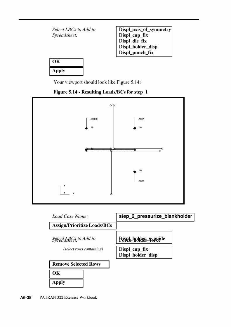
Your viewport should look like Figure 5.14:
Figure 5.14 - Resulting Loads/BCs for step_1
Select LBCs to Add to
Spreadsheet:
Displ_axis_of_symmetry
Displ_cup_fix
Displ_die_fix
Displ_holder_disp
Displ_punch_fix
OK
Apply
Load Case Name: step_2_pressurize_blankholder
Assign/Prioritize Loads/BCs
Select LBCs to Add toSpreadsheet: Displ_holder_y_guideForce_holder_force
(select rows containing) Displ_cup_fix
Displ_holder_disp
Remove Selected Rows
OK
Apply
X
Y
Z
121
16
.1000
16
.09300
16
.1001
X
Y
Z

7/26/2019 Deep Drawing of Cup
http://slidepdf.com/reader/full/deep-drawing-of-cup 39/54
APPENDIX 6 Deep Drawing of a Cylindrical Cup
PATRAN 322 Exercise Workbook A6-39
Your viewport should look like Figure 5.15:
Figure 5.15 - Resulting Loads/BCs for step_2
Your viewport should look like Figure 5.16:
Load Case Name: step_3_move_punch
Assign/Prioritize Loads/BCs
Select LBCs to Add to
Spreadsheet:
Displ_punch_move
(select rows containing) Displ_punch_fix
Remove Selected Rows
OK
Apply
X
Y
Z
11
16
.1000
16
.09300
16
2250.
X
Y
Z

7/26/2019 Deep Drawing of Cup
http://slidepdf.com/reader/full/deep-drawing-of-cup 40/54
A6-40 PATRAN 322 Exercise Workbook
Figure 5.16 - Resulting Loads/BCs for step_3
Your viewport should look like Figure 5.17:
Load Case Name: step_4_release_punch
Assign/Prioritize Loads/BCs
Select LBCs to Add to
Spreadsheet:
Displ_punch_fix
(select rows containing) Displ_punch_move
Remove Selected Rows
OK
Apply
X
Y
Z
11
16
.1000
16
2.450
16
2250.
X
Y
Z

7/26/2019 Deep Drawing of Cup
http://slidepdf.com/reader/full/deep-drawing-of-cup 41/54
APPENDIX 6 Deep Drawing of a Cylindrical Cup
PATRAN 322 Exercise Workbook A6-41
Figure 5.17 - Resulting Loads/BCs for step_4
Your viewport should look like Figure 5.18:
Load Case Name: step_5_release_holder
Assign/Prioritize Loads/BCs
Select LBCs to Add to
Spreadsheet:
Force_holder_reduce
(select rows containing) Force_holder_force
Remove Selected Rows
OK
Apply
X
Y
Z
11
16
.1000
16
.09300
16
2250.
X
Y
Z

7/26/2019 Deep Drawing of Cup
http://slidepdf.com/reader/full/deep-drawing-of-cup 42/54
A6-42 PATRAN 322 Exercise Workbook
Figure 5.18 - Resulting Loads/BCs for step_5
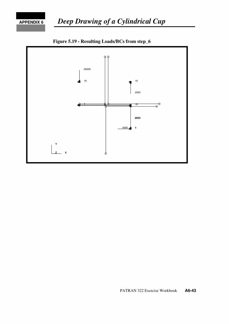
Your viewport should look like Figure 5.19:
Load Case Name: step_6_release_die
Assign/Prioritize Loads/BCs
Select LBCs to Add to
Spreadsheet:
Displ_cup_lift
Displ_die_releaseDispl_holder_raise
(select rows containing) Displ_die_fix
Displ_holder_y_guide
Force_holder_reduce
Remove Selected Rows
OK
Apply
X
Y
Z
11
16
.1000
16
.09300
16
10.00
X
Y
Z
7/26/2019 Deep Drawing of Cup
http://slidepdf.com/reader/full/deep-drawing-of-cup 43/54
APPENDIX 6 Deep Drawing of a Cylindrical Cup
PATRAN 322 Exercise Workbook A6-43
Figure 5.19 - Resulting Loads/BCs from step_6
X
Y
Z
1 16
.2000
1
6.4000
.4000
16
.09300
16
.2000
X
Y
Z

7/26/2019 Deep Drawing of Cup
http://slidepdf.com/reader/full/deep-drawing-of-cup 44/54
A6-44 PATRAN 322 Exercise Workbook
28. Create the Analysis Steps and submit the Analysis.
In this section, you are going to create each of the consecutive stepsfor the analysis. For each step, you will define the step name, solutiontype, solution parameters, corresponding load case, and outputrequests.
Analysis
Action: Analyze
Object: Entire Model
Method: Full Run
Job Name: cup
Optional Controls...
Results File Format: ASCII
Apply
Step Creation...
Job Step Name: step_1
Solution Type: Nonlinear Static
Solution Parameters...
Max No. of Increments Allowed: 100
Minimum Delta-T: 1.0E-5
OK
Select Load Cases...
Available Load Cases: step_1_close_blankholder
OK
Output Requests...
Stress Components: Integ Point
Strain Components: None
Plastic Strains: Integ Point
Displacement: ON
OK
Apply

7/26/2019 Deep Drawing of Cup
http://slidepdf.com/reader/full/deep-drawing-of-cup 45/54
APPENDIX 6 Deep Drawing of a Cylindrical Cup
PATRAN 322 Exercise Workbook A6-45
Repeat the Step Creation Procedure for remaining 5 Load Cases withthe parameters and names given below. Use the same Output Requestsfor all steps
Table 2: STEP 2
Step Creation
Job Step Name: step_2
Solution Type: Nonlinear Static
Solution Parameters
Max. No. Increments Allowed : 100
Minimum Delta-T: 1.0E-5
Load Case
Load Case: step_2_pressurize_blankholder
Output Requests
Stress Components: Integration Point
Plastic Strains: Integration Point
Displacements: ON
Table 3: STEP 3
Step Creation
Job Step Name: step_3
Solution Type: Nonlinear Static
Solution Parameters
Max. No. Increments Allowed : 500
Minimum Delta-T: 1.0E-8
Load Case
Load Case: step_3_move_punch

7/26/2019 Deep Drawing of Cup
http://slidepdf.com/reader/full/deep-drawing-of-cup 46/54
A6-46 PATRAN 322 Exercise Workbook
Output Requests
Stress Components: Integration Point
Plastic Strains: Integration Point
Displacements: ON
Table 4: STEP 4
Step Creation
Job Step Name: step_4
Solution Type: Nonlinear Static
Solution Parameters
Max. No. Increments Allowed: 200
Minimum Delta-T: 1.0E-8
Load Case
Load Case: step_4_release_punch
Output Requests
Stress Components: Integration Point
Plastic Strains: Integration Point
Displacements: ON
Table 5: STEP 5
Step Creation
Job Step Name: step_5
Solution Type: Nonlinear Static
Solution Parameters
Max. No. Increments Allowed : 100
Minimum Delta-T: 1.0E-5
Load Case
Load Case: step_5_release_holder
Output Requests
Table 3: STEP 3

7/26/2019 Deep Drawing of Cup
http://slidepdf.com/reader/full/deep-drawing-of-cup 47/54
APPENDIX 6 Deep Drawing of a Cylindrical Cup
PATRAN 322 Exercise Workbook A6-47
When you are finished creating each of the steps, press Cancel on theStep Create form to close it.
Stress Components: Integration Point
Plastic Strains: Integration Point
Displacements: ON
Table 6: STEP 6
Step Creation
Job Step Name: step_6
Solution Type: Nonlinear Static
Solution Parameters
Max. No. Increments Allowed : 120
Minimum Delta-T: 1.0E-5
Load Case
Load Case: step_6_release_die
Output Requests
Stress Components: Integration Point
Plastic Strains: Integration Point
Displacements: ON
Cancel
Step Selection...
Selected Job Steps: Step_1, Step_2, Step_3,
Step_4, Step_5, Step_6
(be sure to select in order)
Apply
Apply
Table 5: STEP 5

7/26/2019 Deep Drawing of Cup
http://slidepdf.com/reader/full/deep-drawing-of-cup 48/54
A6-48 PATRAN 322 Exercise Workbook
After the analysis is submitted, close the database using File/Close.
At this point the analysis is running. You can monitor the analysisfrom a UNIX windows by monitoring the cup.sta and cup.msg files.You can use the UNIX commands more, cat or tail. The usage of tailis given below. The usage may very slightly depending upon platform(you can use man tail to get UNIX manual help on tail)
tail -lf cup.msg
tail -lf
29. Reading Results
Once the analysis has finished you will read in the results into adatabase. However, often times multi-step nonlinear jobs are ratherlarge in size and may require several refinements on the analysis toobtain the correct results and convergence. You can read in the resultsto the same database if you wish. However, often times its moreefficient to read in the results into a NEW database. Therefore, if theresults are not exactly as you wish, you have not increased the size of the original model database significantly.
Switch the Application to Analysis
File/Close
File/New ...
Database Name: cup_results.dbOK
Analysis Code: MSC/ADVANCED_FEA
Approximate Maximum Model
Dimension: 10
OK
Analysis
Action: Read Results
Object: Both
Method: Translate
Select Results File...

7/26/2019 Deep Drawing of Cup
http://slidepdf.com/reader/full/deep-drawing-of-cup 49/54
APPENDIX 6 Deep Drawing of a Cylindrical Cup
PATRAN 322 Exercise Workbook A6-49
Note: when both is selected, only the node and element connectivity isread in, none of the Material data, LBC’s or Element Property data isavailable in the database.
When the model re-appears, the results translation is complete.
Select Display from the Main Menu.
Select Results from the Display menu.
Select the Deformation Attributes icon
Switch the Application to Results
Selected Results File: cup.fil
OK
Apply
Display/Finite Elements...Show Only Free: Edges
Apply
Cancel
Display/Load/BC/Elem.Props...
Loads/BCs: Hide All
ApplyCancel
Results
Scale Interpretation: True Scale
Scale Factor: 1.0
Show Undeformed Entities

7/26/2019 Deep Drawing of Cup
http://slidepdf.com/reader/full/deep-drawing-of-cup 50/54
A6-50 PATRAN 322 Exercise Workbook
Use the Quick Plot option to look at the results at the end of each step.
Click on the Select Results icon
The figures of the deformed plots at the point of full punch penetrationare shown below:
Figure 5.20 - Resulting deformation from step_1
Results
Action: Create
Object: Quick Plot
Select Results Cases: select the last increment of
each step.
Select Deformation Result: Deformation, Displacement
Apply
X
Y
Z

7/26/2019 Deep Drawing of Cup
http://slidepdf.com/reader/full/deep-drawing-of-cup 51/54
APPENDIX 6 Deep Drawing of a Cylindrical Cup
PATRAN 322 Exercise Workbook A6-51
Figure 5.21 - Resulting deformation from step_2
Figure 5.22 - Resulting deformation from step_3
X
Y
Z
X
Y
Z

7/26/2019 Deep Drawing of Cup
http://slidepdf.com/reader/full/deep-drawing-of-cup 52/54
A6-52 PATRAN 322 Exercise Workbook
Figure 5.23 - Resulting deformation from step_4
Figure 5.24 - Resulting deformation from step_5
X
Y
Z
X
Y
Z

7/26/2019 Deep Drawing of Cup
http://slidepdf.com/reader/full/deep-drawing-of-cup 53/54
APPENDIX 6 Deep Drawing of a Cylindrical Cup
PATRAN 322 Exercise Workbook A6-53
Figure 5.25 - Resulting deformation from step_6
When done viewing, close the database and quit PATRAN.
This concludes the exercise.
X
Y
Z

7/26/2019 Deep Drawing of Cup
http://slidepdf.com/reader/full/deep-drawing-of-cup 54/54