deep diverting gels for very cost-effective waterflood control
TRANSCRIPT
Journal o f Petroleum Science and Engineering, 7 1992) 33-43 Elsevier Science Publishers B.V., Amsterdam
33
Deep diverting gels for very cost-effective waterflood control
A.J.P. Fletcher a,*, S. Flew a, I.N. Forsdyke a, J.C. Morgan a, C. Rogers a and D. Suttles b aBP Sunbury Research Centre, Chertsey Road, Sunbury-on-Thames, Middlesex TW16 7LN, Great Britain
bBp Exploration (Alaska) Inc., P.O. Box 196612, 900E Benson Boulevard, Anchorage, Alaska, USA
(Received March 15, 1991 ; accepted after revision September, 1991 )
ABSTRACT
Fletcher, A.J.P., Flew, S., Forsdyke, I.N., Morgan, J.C., Rogers, C. and Suttles, D., 1992. Deep diverting gels for very cost- effective waterfiood control. In: O. Vikane (Editor), Enhanced Oil Recovery. J. Pet. Sci. Eng., 7: 30-43.
Placement of gels in depth is an effective approach to improving waterflood sweep efficiency, particularly in layered reservoirs. The process can give significant and timely additional oil, compared with the waterflood baseline. It can be low cost, and operationally convenient. There are a number of possible approaches to ensuring gel is formed where needed, and nowhere else. In the present case, advantage is taken of the thermal gradient set up when cold water is injected into a hot reservoir (or aquifer). The position of the cold front can be modelled to an accuracy at least sufficient enough to ensure correct gel placement.
Prediction of gel formation, gel properties and reservoir response is discussed. This includes robustness to uncertainties in process and reservoir description. A slimtube evaluation of a commercial polymer/crosslinker system is also discussed. A satisfactory fit with the kind of performance needed, as determined by predictive reservoir simulation, is shown. This includes demonstration of temperature-initiated gel placement beginning at 50 m depth in a pressure-tapped slimtube. Finally, options for field application and future potential are outlined.
Introduction
It is rare to obtain in practice a waterflood sweep efficiency approaching theoretical per- fection. Usually significant mobile oil still re- mains in the reservoir when the producing wa- tercut exceeds the economic limit (usually at a WOR of about 50:1 for individual wells). There are several reasons for this. Geological layering leads to poor vertical sweep conform- ance. Depositional history can also lead to non- uniform areal sweep, which can be a problem unless contracted by offset injector/producer
Correspondence to: J.C. Morgan, BP Sunbury Research Centre, Chertsey Road, Sunbury-on-Thames, Middlesex TW 16 7LN, Great Britain. *Present address: The Petroleum Science & Technology Institute, Research Park, Riccarton, Edinburgh, EH14 4AS, Great Britain.
alignment. Vertical and areal sweep efficien- cies can both be adversely affected by natural or induced fractures. Other factors include water underrunning because of gravity segre- gation and coning, particularly of bottom aquifers.
The obvious place to correct waterflood sweep is at the injectors or producers, which is where the problem is seen and where the target is best defined. At the producer end, the objec- tives are to increase the oil flow rate and (sep- arately) to reduce water production. At the in- jector end the objective is to direct more water into the tighter zones.
Because their higher success rate, producer treatments (using cement squeezes, or strong polymer gels etc. ) are most popular. They still have a quite high failure rate where the bene- fit, if any, does not pay for the treatment cost
0920-4105/92/$05.00 © 1992 Elsevier Science Publishers B.V. All rights reserved.
34
plus the value of oil deferred by the necessary shut-in. If there is communicat ion between layers by cross-flow or in the well completion, then any water being forced to the producer by reservoir pressure gradients will fairly quickly find a way around the placed blockage.
However, if targets are selected judiciously and treatment is technically successful then economic production can be prolonged. There are sufficient successes to outweigh failures and to maintain active use of producer treatments, though not all of these economic successes ac- tually have much effect on reservoir recovery factors.
Injector treatments have an advantage in principle because they do not require shut-in of production. Therefore, prolonged treat- ments and shut-in times become less of a prob- lem. Also, correction of any mishaps is vir- tually always successful, which cannot be guaranteed for producers. Injectors are rarely lost in practice. However, the economic failure rate for injector treatments is higher than for producer treatments. Again, cross-flow be- tween layers is a problem. Even when a spin- ner survey shows successful diversion of injec- tion from a thief zone into the unswept lower permeability layers, water may go straight back into the thief a few metres beyond the placed blockage. Also, injecting cold water into a hot reservoir will lead to reduction of the com- pressive stress below the formation fracture pressure (Clifford et al., 1990; Fletcher et al., 1990). Thermally-induced fractures will con- tinue to grow as injection proceeds, though they usually advance more slowly than the wa- terflood front. This is good for water injection, which would otherwise be gradually impaired (Fletcher et al., 1990; Clifford et al., 1991 ), but has serious implications for the design of near-wellbore injector treatments for water di- version. Thus a deep treatment should prove to be successful more often than a near-well- bore system as it overcomes some of these un- certainties. Placement of a treatment away from the high-pressure gradient zone around
the wellbore will also result in less injectivity impairment, and allow for injection rates to be maintained.
The deep diverting gel (DDG) approach came about in part from the above considera- tions. We were led to treat a reservoir with "average" cross-flow characteristics (Kv:Kh of 0.1 ), "typical" thermal fracture lengths (from injection of seawater at 25 °C into a reservoir at about 70°C), with between 1 and 3 thief zones (with Kh= 800 to 1500 mD) and a high permeability contrast with other layers. There was a strong preference not to pack off thief zones while they were treated, because the well completion design was not compatible with this in all injectors. The best option seemed to be a non-selective in-depth injector treatment. At an early stage, viscous polymer flooding was precluded because in other studies economic correction of profile control was only possible where there was also an adverse oil: water mo- bility ratio. Numerical simulation showed that without this, so much polymer was needed that injection became very slow (or else fractures became too long). The residence time of the polymer in the thief zone was also too short unless a very large treatment was used, and then polymer started to enter the low permea- bility zones. The concept of forming a block- ing agent of moderate strength some distance out and only in the thief zones was most attractive.
The first requirement was to form a view of the blocking characteristics needed, and to identify a system with something like these characteristics. It was also necessary to show that the reservoir response would be reliably positive, and would be insensitive to changing or uncertain reservoir and system properties. A combination of laboratory tests, numerical simulation, and some luck, showed how this could be achieved in practice by utilising a polymer/crosslinker combination already em- ployed in near-well treatments. The concepts described here should be applicable to prop- erly selected target wells in reservoirs with ini-
tial temperature above about 50°C and with poor vertical sweep conformance.
Principles of deep gel application
Throughout the evaluation of these gels, nu- merical modelling, laboratory development and the field group worked together. From the start the experimentalists got a continuously updated visualisation of their gel's behaviour in the reservoir from 3D predictions. Also it kept the exploratory simulation in touch with physically realistic system parameters, and with best knowledge of physical and chemical gelling mechanisms, and with the best target reservoir description.
A few promising early systems were eventu- ally shelved because their gel formation could not be restricted to the thief zones, or because insufficient production response was pre- dicted, or because injection well pressure was too sensitive to gellation control.
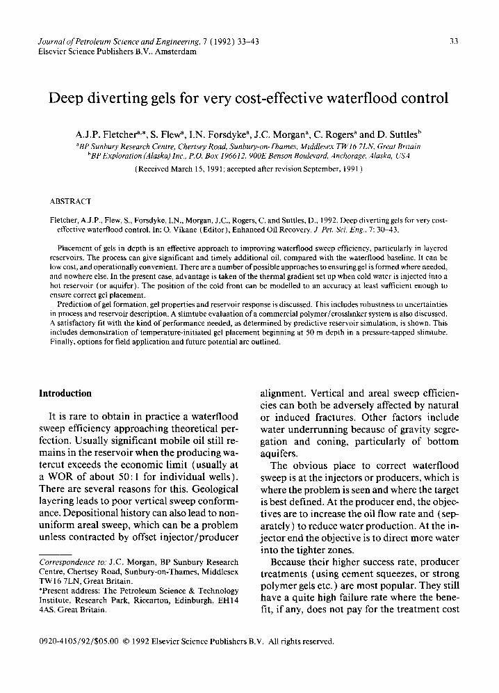
The selected version is conceptualized in Fig. 1. The key factors are as follows. Reservoir de- scription is always a difficult problem in wa- terflooding, and improved waterflooding pro- cesses add another layer of uncertainty and risk. However, the reservoir temperature and the injection water temperature are known, as is the amount of water injected. Usually the reservoir thickness and the primary water ac-
Cold water injection Production
t
Fig. 1. Deep flood division.
35
cepting intervals are also well known, though this is not too critical in the present context. The heat capacity and thermal conductivity can be estimated quite accurately. This means that the temperature gradient set up by cold water injection can be predicted more accu- rately than most other reservoir features. The cold front moves more slowly than the water- flood front. It is also much more uniform than the waterflood front, because thermal conduc- tivity between layers tends to wipe out thermal fingers. (Thick thief zones do show some fingering. )
This temperature variation can be used to advantage. First a med ium molecular weight polymer and a crosslinker are selected which essentially do not give blocking in the porous matrix in the cold, but do give blocking if heated. These are both co-injected into the wa- terflood at low concentrations for a short pe- riod only. Most of the dissolved chemicals en- ter the thief zones. They have to follow the major established water paths wherever they go. Injectivity is not changed because viscosity is not affected. The chemicals quickly catch up with the cold front, and begin to block the thief zones. The follow up water begins to be di- verted out of the thief zones and into the neighbouring zones from upstream of the blockages. Of course, some chemicals will be injected into the lower permeability zones, but not much. Generally, even these chemicals are lost by adsorption and dispersion long before they get to the hot zone. A fuller discussion of diversion characteristics and the changes (if any) to be seen in the zones taking injection is deferred until later. However, the net result is that more water passes through the lower permeability zones, and more oil and less water are delivered to the producers.
Gel placement studies
Materials
These studies were based on a medium mo- lecular weight, low anionic content polyacry-
36
lamide (from Allied Colloids, UK and USA) together with a luminium citrate crosslinker (Magnablend, USA). This low toxicity system was selected because chemical reaction could be kept under control with about the right con- centration of crosslinker (high enough to overcome adsorption losses, low enough to keep costs and logistics acceptable). The po- lyacrylamide was stable, was not dilatent dur- ing injection, and had low effective shear viscosity.
The slimtubes used in placement tests were usually of non-ferrous metal (monel) . This was to avoid possible difficulties from ferric ion crosslinking, given the high surface-to-volume ratio of the slimtubes and the very long exper- iment duration (up to four months) . The for- mation water used was a high salinity brine (30,000 TDS). Oil was well head crude from Kuparuk (North Slope, Alaska) and Forties (North Sea) reservoirs. Waterflood and gel flood used either Dorset (UK) seawater or a synthetic equivalent from BDH (Poole, Dor- set). Tracers used included li thium as the chloride (it was seen that during waterflood- ing seawater always completely displaced all formation water still present after oil flood- ing). Formaldehyde (500 ppm) was used as biocide in the gel flood.
Slimtube tests of in depth gel placement
A battery of ancillary tests such as bulk gel- lation rates, extensional rheology, dialysis, fil- tration, etc., built up a helpful picture of gel characteristics. However, it was still very dif- ficult to predict blocking characteristics in a porous medium from behaviour outside it. Therefore to avoid doubts on scale-up, there was a need to run in-depth tests.
The objective was to show that gel could be placed well away from the injector. Prior to this, the chemicals would have to pass through a cooled zone without gelling. Sand-packed slimtubes with thief zone permeabilities (up to 5 D) were used to demonstrate this. The
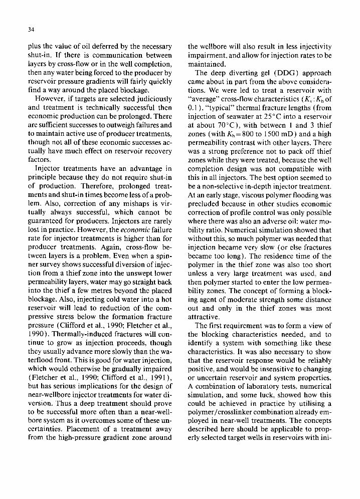
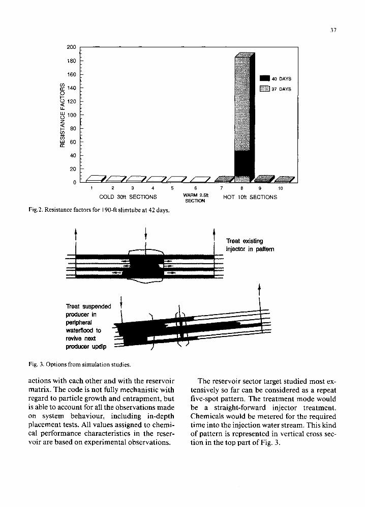
tubes were pressure tapped along their length. The reservoir temperature gradient was quali- tatively represented by having the upstream end of the slimtube in a temperature-con- trolled laboratory (at 25°C) and the down- stream end in a thermostat. The longest slim- tube used had five cool sections, each 10 m long, then a one-metre warming section, and then four hot sections at 70°C, each 3 m long. Because relevant reservoir flow rates (2 m / day) were used during waterflooding to resid- ual saturation and during the gel test, this test took well over three months to complete.
The blocking behaviour from continuous injection of polyacrylamide (500 ppm) and a luminium citrate (300 ppm aluminium) is seen in Fig. 2. Essentially the chemicals moved through the cool zones without blocking. When they reached some distance into the hot zone, they blocked it. Here, resistance factor is the pressure drop across the section divided by the pressure drop seen previously to water flow through the same section at the end of the wa- terflood stage.
Shorter slim-tubes, up to 20 m long, run at different temperatures, and short core flood tests were used to obtain further data on injec- tivity and adsorption of polymer and cros- slinker. This data was used as input for the predictive simulation discussed below.
Reservoir sector simulation
Reservoir sector numerical modelling used BPOPE, a three-dimensional, multiphase, mul t icomponent IMPES code. This was based on UT Chem, originally developed at the Uni- versity of Texas. In-house modifications and additions included compressibility, modelling of the thermal gradient development, dynamic thermal/hydraul ic fracturing based on rock mechanics, generalized grid structures, gener- alized boundary condition options, multiwell set-ups, implicit well controls, extensive vec- torization and, of course, a chemical reaction scheme to handle polymer/crosslinker inter-
200
180
160
r r 140 O I - O 120 ,< LL
100 Z < I-- 80 r./) ,q') LU 60 r r
40
20
1 2 3 4
COLD 30ft SECTIONS
Fig.2. Resistance factors for 190-ft slimtube at 42 days.
6
WARM 2.5ft SECTION
m 40 DAYS
37 DAYS
7 8 9 10
HOT 10ft SECTIONS
37
Treat existing injector in pattern
Treat suspended producer in peripheral waterflood to revive next producer updlp
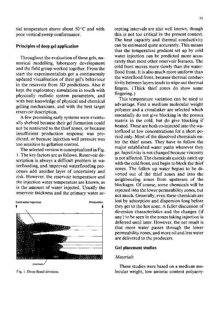
Fig. 3. Options from simulation studies.
actions with each other and with the reservoir matrix. The code is not fully mechanistic with regard to particle growth and entrapment, but is able to account for all the observations made on system behaviour, including in-depth placement tests. All values assigned to chemi- cal performance characteristics in the reser- voir are based on experimental observations.
The reservoir sector target studied most ex- tensively so far can be considered as a repeat five-spot pattern. The treatment mode would be a straight-forward injector treatment. Chemicals would be metered for the required time into the injection water stream. This kind of pattern is represented in vertical cross sec- tion in the top part of Fig. 3.
38
o
Illllilllllll I 1 tt t I l l I Ilt~lll Ill l ~ \ \ \ \ ' % ~ , \ ~ \ \ \ \ \ \ \ \ \ \ \ \ \ \ \ \ \ \ \ \ \ \ \ \ \ \ \ \ \ \ \ \ \ \ \ \ \ \ \ \ \ \ \ \ \ \ \ \ ~ \ \ \ \ \ \ \ \ ~ \ \ \ \ \ \ \ \ \ \ \ \ \ \ \ \ \ \ \ \ \ ~ ~ . \ ~ \ \ \ \ \ \ \ \ \ \ ' ~
[ I I I I [ I I I I I 1 1 1 L I [ I I I I I l i l l l l l I I I I 1 [ I I t I I t I I I I ] ~ I I I I [ I I I I I I I I I I I I I I I I I I I I I I I I I I I I I I I I I I I I I I I I l l l l I l t l l l l l l l l l I 1 ~ 1 1 1 1 1 1 1 [ I I I I I I I I I I I I I I I I I I T I
8 3 0 2 6 4 0
~ m ~ ~ ~ ~ ~ ~ 50 100 250 400 900 1000] 0 1 2 0
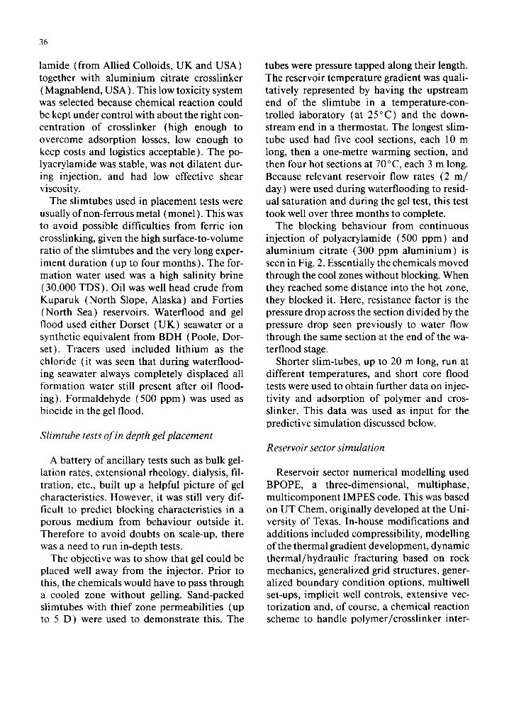
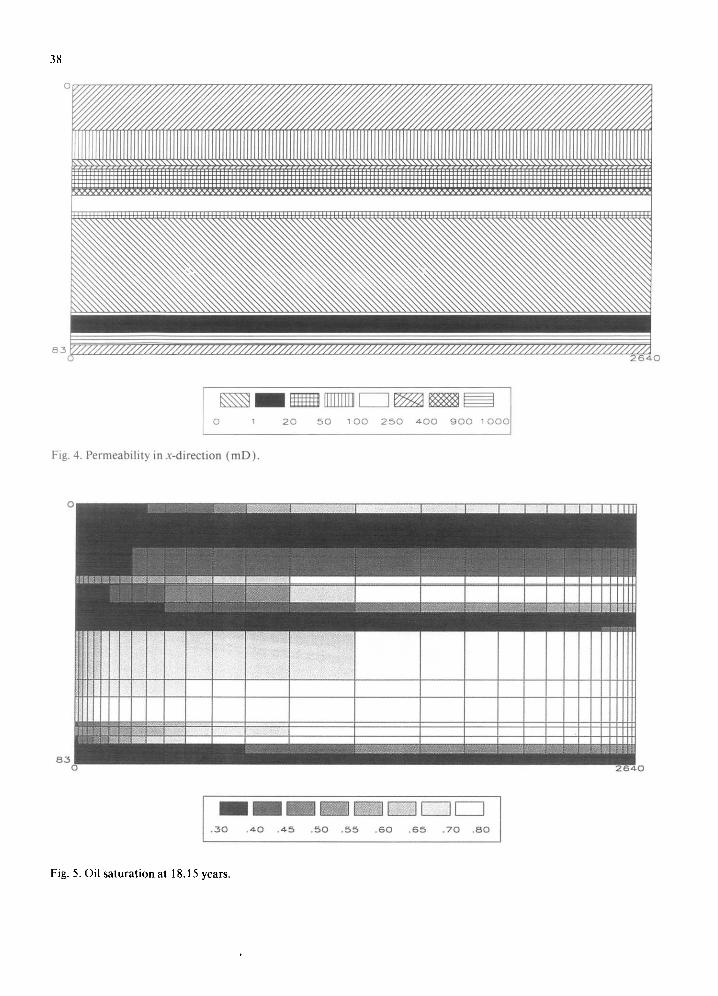
Fig. 4. Permeability in x-direction (mD) .
¢
8 2 0
m m m m ~ ~ ~F-q . 3 0 . 4 0 . 4 5 . 5 0 . 5 5 . 6 0 . 6 5 . 7 0 . 8 0
Fig. 5. Oil saturation at 18.15 years.
C'l i l l l l l l ~
IIIIU N~ ~ :
lilfl|~ I l l l m E ~ i ~ : . [
iiim||~il : Iiimlul~
;llllli~': ? llllhr.! | l lulam~;:~;:
I I l I I R
I l l l l l~ i~i : i 8.3
r-q~ ~ ~ m m m n 7 3 84 - 9 ,5 1 0 6 1 1 8 1 2 9 1 4 1 1 : 5 2 1 6 . 3
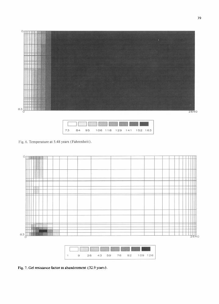
Fig. 6. Tempera tu re at 5.48 years (Fah renhe i t ) .
o ! :;i::
lIM
I I~ lii)i~ iiii:i iii:.ii~
39
I I I I
i n l I I I i l l
I' 1in
i L I L
2 6 4 0
r--- 1
1 ~ w ~ ~ n m 9 2 6 4 5 5 9 7 6 9 2 1 0 9 1 2 6
Fig. 7. Gel resistance factor at a b a n d o n m e n t (32.9 years) .
40
In BPOPE, this t reatment has been mo- delled as a 3D quarter five-spot, using a diag- onal grid when the thermal fracture code is needed. Run execution times are much shorter using a 3D eighth five-spot curvilinear grid, used for sensitivity studies where the fracture code option is not required. The 17-layer hor- izontal permeability description used in this BPOPE study is shown in Fig. 4.
There are major thief zones at the top and bot tom of this 27-m thick reservoir, and a smaller thief zone in the middle. This leads to poor predicted vertical waterflood sweep con- formance, and a large mobile oil target will re- main at the conventional waterflood abandon- ment point after 18 years (Fig. 5 ).
At the t ime of modelling, 5.5 years after wa- terflood start, the cold front had only moved about 100 m (the well to well distance is 800 m) and was quite uniform (Fig. 6).
The addit ion to the injection water of poly- acrylamide ( 500 ppm ) and a luminium citrate (300 ppm) for 120 days (total about 2% of
pattern PV) leads to rapid development of higher resistance factors in the thief zones, particularly the top and bot tom thiefs (Fig. 7 ). The simulation has been run on to 33 years here to show that no blockage of other zones is ever expected.
In terms of expected diagnostics, there would
Treatment Window
200 il Production/~"
400
0 v
rn(2" tm -6O0400800200 ~ p ~ /
i I i , 1000 2000 3000 4000
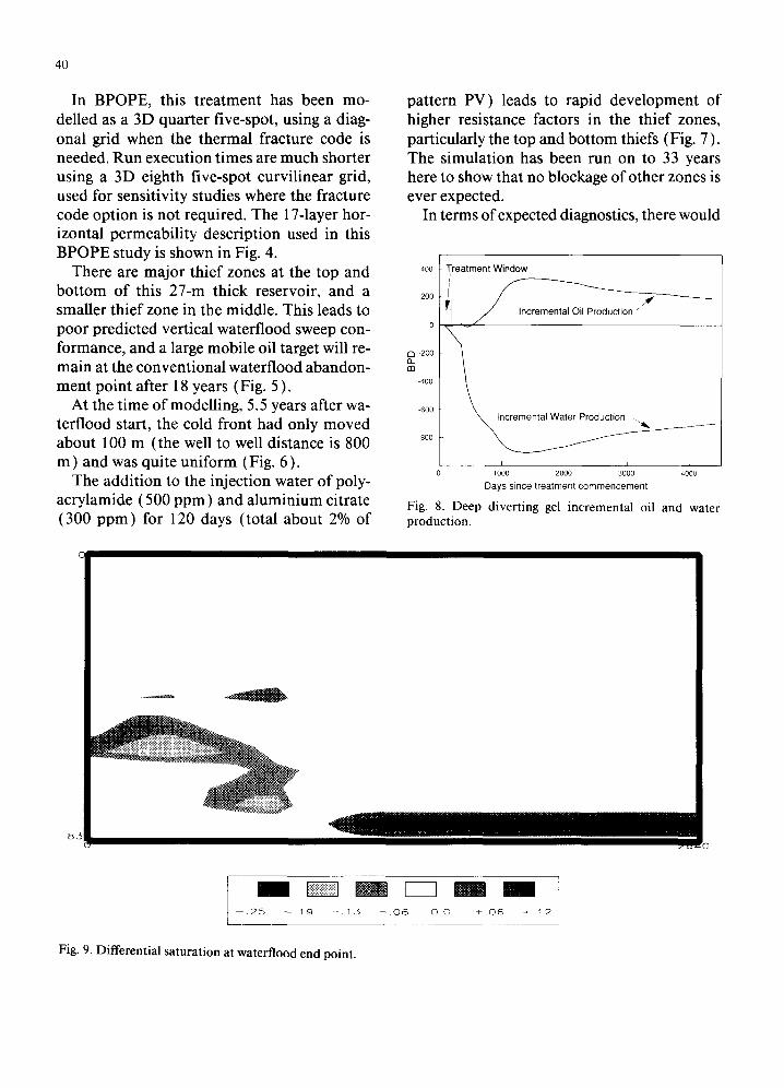
Days since treatment commencement Fig. 8. Deep diverting gel incremental oil and water production.
8~
m r--i m --.25 --.19 --.15 --.06 0.0 +.06 +.12
Fig. 9. Differential saturation at waterflood end point.
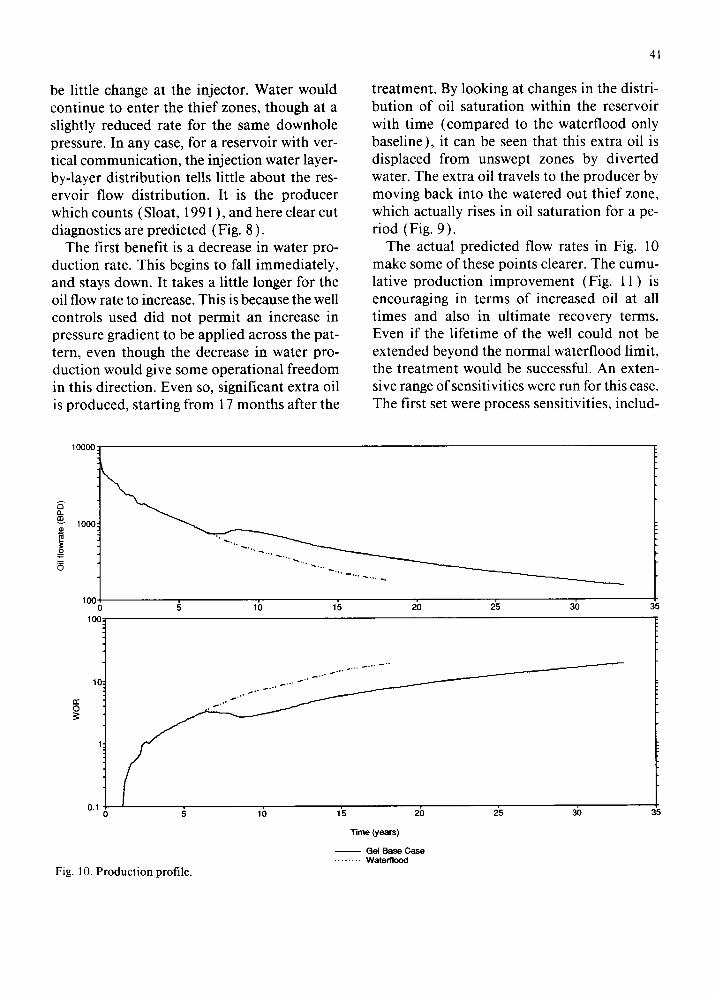
be little change at the injector. Water would continue to enter the thief zones, though at a slightly reduced rate for the same downhole pressure. In any case, for a reservoir with ver- tical communication, the injection water layer- by-layer distribution tells little about the res- ervoir flow distribution. It is the producer which counts (Sloat, 1991 ), and here clear cut diagnostics are predicted (Fig. 8 ).
The first benefit is a decrease in water pro- duction rate. This begins to fall immediately, and stays down. It takes a little longer for the oil flow rate to increase. This is because the well controls used did not permit an increase in pressure gradient to be applied across the pat- tern, even though the decrease in water pro- duction would give some operational freedom in this direction. Even so, significant extra oil is produced, starting from 17 months after the
41
treatment. By looking at changes in the distri- bution of oil saturation within the reservoir with time (compared to the waterflood only baseline), it can be seen that this extra oil is displaced from unswept zones by diverted water. The extra oil travels to the producer by moving back into the watered out thief zone, which actually rises in oil saturation for a pe- riod (Fig. 9 ).
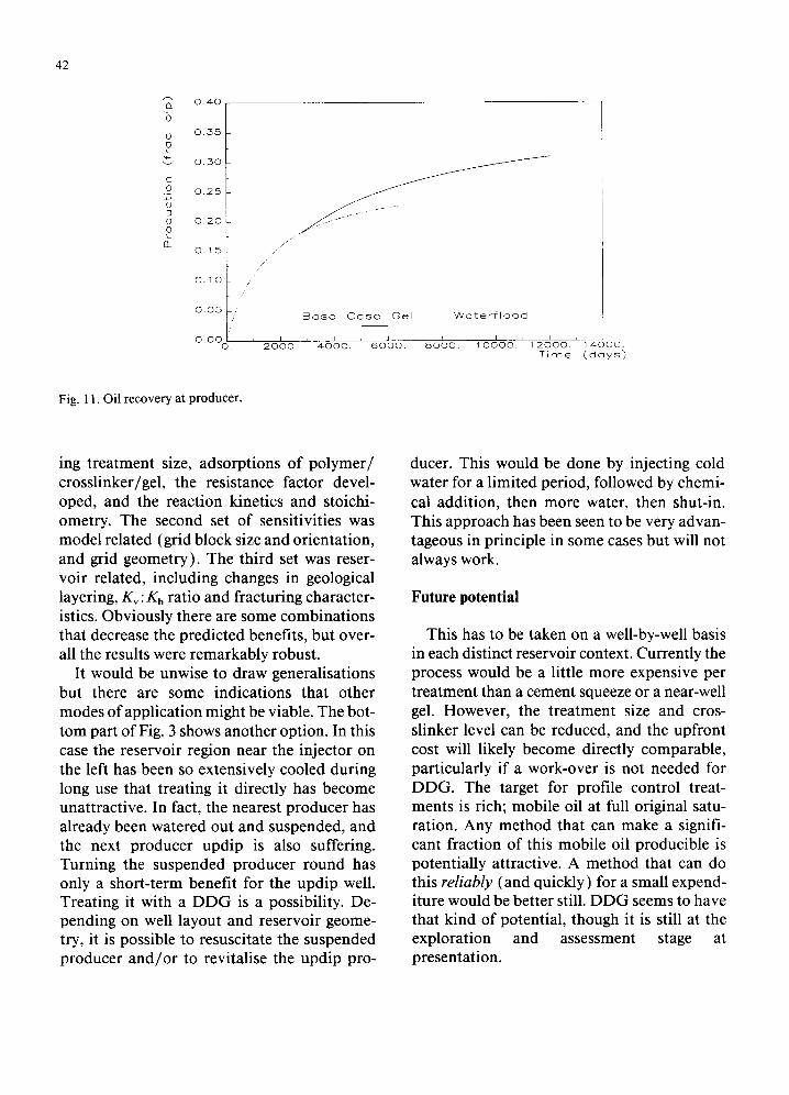
The actual predicted flow rates in Fig. 10 make some of these points clearer. The cumu- lative production improvement (Fig. 11 ) is encouraging in terms of increased oil at all times and also in ultimate recovery terms. Even if the lifetime of the well could not be extended beyond the normal waterflood limit, the treatment would be successful. An exten- sive range of sensitivities were run for this case. The first set were process sensitivities, includ-
10000
a. ,,m 1000
100 0
100: 10 15 2b 2~ 3~ 35
r r 0
10
I "
0 . I 0
~.° .
~ " " f
5 10
Fig. 10. Production profile.
1'5 2()
Time (years)
- - Gel Base C a s e . . . . . . . . Waterflood
3b 3 5
42
O_ '6 0 0
v
0 D
73 O
CL
0 . 4 0
0 . 3 5
0 . 3 0
0 . 2 5
0 . 2 0
0 . 1 5
0 . 1 0
0 . 0 5 " "
O . O 0 O.
f /
/
I 2 0 0 0 .
E 3 o s e C a s e G e l W a t e r f l o o d
4 0 0 0 . 6 0 0 0 . 8 0 0 0 . 1 0 0 0 0 . I i
1 2 0 0 0 . 1 4 0 0 0 . T i m e ( d a y s )
Fig. 11. Oil recovery at producer.
ing treatment size, adsorptions of polymer / crosslinker/gel, the resistance factor devel- oped, and the reaction kinetics and stoichi- ometry. The second set of sensitivities was model related (grid block size and orientation, and grid geometry). The third set was reser- voir related, including changes in geological layering, Kv: Kh ratio and fracturing character- istics. Obviously there are some combinations that decrease the predicted benefits, but over- all the results were remarkably robust.
It would be unwise to draw generalisations but there are some indications that other modes of application might be viable. The bot- tom part of Fig. 3 shows another option. In this case the reservoir region near the injector on the left has been so extensively cooled during long use that treating it directly has become unattractive. In fact, the nearest producer has already been watered out and suspended, and the next producer updip is also suffering. Turning the suspended producer round has only a short-term benefit for the updip well. Treating it with a DDG is a possibility. De- pending on well layout and reservoir geome- try, it is possible to resuscitate the suspended producer and /o r to revitalise the updip pro-
ducer. This would be done by injecting cold water for a limited period, followed by chemi- cal addition, then more water, then shut-in. This approach has been seen to be very advan- tageous in principle in some cases but will not always work.
Future potential
This has to be taken on a well-by-well basis in each distinct reservoir context. Currently the process would be a little more expensive per treatment than a cement squeeze or a near-well gel. However, the treatment size and cros- slinker level can be reduced, and the upfront cost will likely become directly comparable, particularly if a work-over is not needed for DDG. The target for profile control treat- ments is rich; mobile oil at full original satu- ration. Any method that can make a signifi- cant fraction of this mobile oil producible is potentially attractive. A method that can do this reliably (and quickly) for a small expend- iture would be better still. DDG seems to have that kind of potential, though it is still at the exploration and assessment stage at presentation.
Conclusions
( 1 ) The ability to block thief zones by in-depth gel placement can be demonstrated in long laboratory slim-tubes.
( 2 ) From predictive simulation, the Deep Di- verting Gel approach to waterflood pro- file control problems could lead to signif- icant incremental oil recovery plus a decrease in water cycling through thief zones.
(3) DDG should not be affected adversely by crossflow or thermal fractures, and should be reliable in use. Sensitivity studies indi- cate robustness.
43
Acknowledgement
The permission of British Petroleum to pub- lish the reported work is gratefully acknowledged.
References
Clifford, P.J., 1991. 3rd SPE Bahrain Conference (postponed).
Clifford, P.J., Berry, P.J. and Gu, H., 1990. Modelling of vertical confinement of injection well thermal frac- tures. SPE 20 741, Annu. Conf. SPE, New Orleans, La.
Fletcher, A.J.P., Lamb, S.P. and Clifford, P.J., 1990. Fac- tors governing formation damage and injectivity of polymers, SPE/DOE 20243, SPE/DOE 7th Symp., Tulsa, Okla.
Sloat, B.J., 1991. Measuring engineered oil recovery. J. Pet. Technol., 43( 1 ): 8-13.