decomposition of silicon tetrachloride by microwave plasma jet at atmospheric pressure
TRANSCRIPT

ISSN 0020-1685, Inorganic Materials, 2009, Vol. 45, No. 12, pp. 1403–1407. © Pleiades Publishing, Ltd., 2009.
1403
1
INTRODUCTION
The semiconductor industry in the large-scale use ofsilane produces a large number of halogenated silane influe gases. Such undesirable waste is usually disposedof by dumping in depots or discharge into the aquaticmedium or the atmosphere. This has resulted in increas-ing contamination of ground water and degradation oftropospheric ozone [1]. Silicon tetrachloride, one ofvolatile compounds in flue gases, easily brings healthhazards in the air. Recently, a number of technologiesfor destroying such environmental hazards rangingfrom air pollutants to solid wastes have so far beentested including thermal decomposition [2], catalyticoxidation [3], biofiltration, carbon adsorption, mem-brane separation, UV oxidation [4], condensation andplasma-based procedures [5].
As we known, non-thermal plasmas provide analternative method for generating highly reactive spe-cies; in which electrons are accelerated by the appliedelectrical fields and transfer their energy via elastic andnon-elastic collisions with neutral molecules. The reac-tions occurring under these conditions are usually farfrom thermodynamic equilibrium and result in destruc-tion associated with higher electron temperatures of10000–20000 K, by contrast, the neutral gas remains atmuch lower temperatures. This mechanism is useful forthe applied energy to generate radicals and excitedatomic and molecular species, thereby facilitating thedecomposition of contaminant molecules. Although thetemperature of a non-thermal plasma is not so highlyinfluential on the destruction efficiency, an increasedtemperature facilitates the process. In addition to
1
The article is published in the original.
enhanced destruction and removal, plasma-basedchemical processes provide some advantages such aslow implementation, operating and capital costs, andmodest facility size requirements, in relation to conven-tional volatile compounds destruction techniques [1].
In this letter, we report a system for destroying SiCl
4
based on a microwave plasma jet (
MPJ
) operating atatmospheric pressure. MPJ at atmospheric pressure hasgained huge potential from industry in recent years as aclean, high-temperature intense energy source for vari-ous applications of material processing [6].
EXPERIMENTAL
The experimental set-up for SiCl
4
destruction andbyproduct analysis consists of two distinct parts,namely: (a) the destruction zone, which includes amicrowave plasma jet operating at atmospheric pres-sure; (b) the analytical systems of atomic emissionspectroscopy.
Figure 1 depicts the proposed SiCl
4
destroying sys-tem. The former comprises a magnetron connected to arectangular waveguide (WR340). They are operated ata frequency of 2.45 GHz and their power is approxi-mately 800 W. The power supply, consisting of a full-wave voltage double circuit, provides the electricalpower to the magnetron, which generates the micro-wave radiation and is cooled by a water-cooledmatched load. The generated microwave radiation fromthe magnetron is guided through the waveguide, passesthrough the three-stub tuner, and enters the dischargepart [7]. The resonant microwave is adjusted by slidingshort circuits and is induced into a copper nozzlelocated at the centre of the reaction section. The center
Decomposition of Silicon Tetrachloride by Microwave PlasmaJet at Atmospheric Pressure
Lifeng Wu , Zhibin Ma, Aihua He, and Jianhua Wang
Province Key Lab of Plasma Chemistry and Advanced Materials, School of Material Science and Engineering, Wuhan Institute of Technology, Wuhan, China
e-mail: [email protected], [email protected]
Received November 2, 2008
Abstract
—A new method for destroying silicon tetrachloride has been developed, which based on a microwaveplasma jet that operates at atmospheric pressure using hydrogen as work gas. Experiments showed that the sil-icon tetrachloride was dissociated into silicon and hydrogen chloride under the effect of the plasma jet. The sil-icon was deposited on the molybdenum substrate of the plasma reactor, which was yellow and typical nano-sized particles. These solid samples have been analyzed by SEM, EDX, XRD, FT-IR and the active particle inthe plasma is detected by atomic emission spectroscopy. The results show that the silicon tetrachloride is mainlytransformed into nano-silicon with size of 54 nm. The dissociation efficiency reaches 50%.
DOI:
10.1134/S0020168509120188

1404
INORGANIC MATERIALS
Vol. 45
No. 12
2009
LI-FENG et al.
axis of nozzle is located one-quarter wavelength fromthe shorted end and is perpendicular to the widewaveguide walls.
For the 2.45 GHz cavity, the modeling results gavethe following optimum condition. The nozzle positionfrom the waveguide cavity short circuit wall is 45 mm,nozzle tip diameter is 2 mm, nozzle hole is 0.5 mm andcavity hole is 20 mm in diameter. This diameter hasbeen optimized to prevent the electrical field frombreaking down inside the cavity and also to stop the jetreflected back into the cavity during the material pro-cessing [8]. Hydrogen was used as a plasma gas andcarrier gas with 100 kPa pressure and a 0.4–0.6 l/minflow rate. The powder was collected by quenching frommolybdenum substrate.
Surface morphology of the powder was studied by ascanning electron microscopy (
SEM
) with JSM5510LV microscope equipped with an EDX analyzer.Crystal structure was detected with a YB-XD-5A X-raydiffraction. Further information about the chemicalstructure was obtained by Impact 420 FT-IR. Atomicemission spectroscopy was used for monitoring excitedspecies in the discharge with WDS-8A grating spec-trometer.
RESULTS AND DISCUSSION
We primarily considered H
2
as a reaction gas, whichwas injected as the carrier gas of the microwave plasmajet. The desired reaction pathway is the following pro-cess.
H
2
2
H
, (1)
H
+
SiCl
4
SiCl
3
+
HCl
,
H
+
SiCl
3
SiCl
2
+
HCl
,
H
+
SiCl
2
SiCl
+
HCl
.
H
+
SiCl
Si
+
HCl
. (2)
H
2
is to deoxidize the silicon in SiCl
4
to Si. The powderdeposited on the substrate was yellow in color.
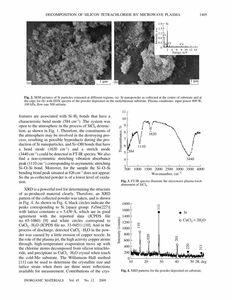
The SEM images of as-produced Si nanoparticlesby the microwave plasma jet are shown in Fig. 2. Bycomparing samples extracted at different regions, alsothe difference between the different agglomerationdegrees can be found. An agglomerate is equal to justone primary particle at the centre of substrate, whereasit is built up out of many primary particles at the edge.When the plasma has a high degree of particle loading(a high precursor feed rate and higher temperatures),the sample containing particles with a small degree ofagglomeration will show a more open and fluffy struc-ture (Fig. 2a), while the sample containing a highdegree of agglomeration shows a dense structure(Fig. 2b). Quenching is the more effective at highertemperatures for centre, and much smaller particles inthe agglomerates can be obtained and have a more openstructure. In order to obtain the information of elementspecies in the powder. EDX survey spectra were used todetermine which elements were present in the powder.Si and oxygen species were detected with atomic frac-tion of 61.42% oxygen and 31.72% silicon consistently.The EDX spectra showed an additional line character-istic of the existence of Cl (due to the chlorine atoms ofSiCl
4
). In addition, the Cu and Al signal is significantlydetected due to a little erosion of copper nozzle and alu-minum fixture around the molybdenum substrate.
Representative FT-IR spectra that show the trans-mittance against wavenumber for specimen is given inFig. 3. Figure 3 are the FT-IR spectra corresponding toSEM images in Fig. 2b, respectively. Strong absor-bance peaks occur at 584, 1110 and
3440
cm
–1
. These
Cool–water Cooper nozzle
Molybdenumsubstrate
Carrier
20 mm
Exhaust gas
Plasma3–Stub tuner
Circulator
2.45 GHzmagnetron
Waveguide
Photomultiplier Flow meters
Spectrometer H
2
SiCl
4
Gas
Fig. 1.
Schematic diagram of the propmosed SiCl
4
destruction set-up.
INORGANIC MATERIALS
Vol. 45
No. 12
2009
DECOMPOSITION OF SILICON TETRACHLORIDE BY MICROWAVE PLASMA 1405
features are associated with Si
–
H
2
bonds that have acharacteristic bend mode (
584
cm
–1
) .The system wasopen to the atmosphere in the process of SiCl
4
destruc-tion, as shown in Fig. 1. Therefore, the constituents ofthe atmosphere may be involved in the destroying pro-cess, resulting in possible byproducts during the pro-duction of Si nanoparticles, and Si–OH bonds that havea bend mode (
1620
cm
–1
) and a stretch mode(
3440
cm
−
1
) could be detected in FT-IR spectra. We alsofind a non-symmetric stretching vibration absorbancepeak (
1110
cm
–1
) corresponding to asymmetric stretchingSi–O–Si bond. Moreover, for the sample the Si–O–Sibending bond peak situated at
826
cm
–1
does not appear.So the as-collected powder is of a lower level of oxida-tion.
XRD is a powerful tool for determining the structureof as-produced material clearly. Therefore, an XRDpattern of the collected powder was taken, and is shownin Fig. 4. As shown in Fig. 4, black circles indicate thepeaks corresponding to Si [space group:
Fd
3
m
(227)
]with lattice constants
a
= 5.430
Å, which are in goodagreement with the reported data (JCPDS fileno. 65-1060) [9] and white circles correspond toCuCl
2
·
H
2
O (JCPDS file no. 33-0451) [10]. And in theprocess of discharge, detected CuCl
2
·
H
2
O in the pow-der was caused by a little erosion of copper nozzle. Inthe role of the plasma jet, the high activity copper atomsthrough, high-temperature evaporation move up withthe chlorine atoms decomposed from silicon tetrachlo-ride, and precipitate as CuCl
2
·
H
2
O crystal when touchthe cold-Mo substrate. The Willamson–Hall method[11] can be used to determine the crystallite size andlattice strain when there are three more reflectionsavailable for measurement. Contributions of the crys-
(a) (b)1
μ
m 1
μ
m
0.4
2 4 6 8 10 12 140
0.8
1.2
1.5
1.9
Inte
nsi
ty, a.
u.
Energy, keV
O
Si
Al Cl Cu
Fig. 2.
SEM pictures of Si particles extracted at different regions, (a): Si nanopowder as collected at the centre of substrate and atthe edge for (b) with EDX spectra of the powder deposited on the molybdenum substrate. Plasma conditions: input power 800 W,100 kPa, flow rate 500 ml/min.
1000 1500 2000 2500 3000 3500 40005003
4
5
6
7
8
9
10
11
584
1110
1620
3440
Tra
nsm
itta
nce
, %
Wavenumber, cm
–1
Fig. 3.
FT-IR spectra illustrate the microwave plasma torchabatement of SiCl
4
.
200
20 30 40 50100
400
600
800
1000
1200
1400
1600
1800
110
020
111
Si
CuCl
2
×
2H
2
O
Inte
nsi
ty (
counts
)
2
θ
, deg
201
220
311
Fig. 4.
XRD patterns for the powder deposited on substrate.

1406
INORGANIC MATERIALS
Vol. 45
No. 12
2009
LI-FENG et al.
tallite size and lattice strain are given by the followingequation:
(3)
where
λ
is the wavelength of the X-rays (
λ
= 1.54
Å inthis experiment),
θ
is the diffraction angle,
η
is the lat-tice strain,
L
is the crystallite size,
k
is a constant (0.94for Gaussian line profiles and small cubic crystals ofuniform size), and
β
is the full width at half maximum(FWHM). In Eq. (3), the Si crystallite size was calcu-lated to be approximately 54 nm in the powder.
A part of a typical atomic emission spectrum mea-sured from a discharge in gases is given in Fig. 5. Thespectrum measurement system can be used to followrelative fluctuations in the gas composition in time. Inthe case of the MPJ, the carrier gas and SiCl
4
are mixedbefore entering the plasma, and the nozzle material hasa strong impact on the plasma properties. The atomicline of copper can be easily distinguished in the shownspectral range between 320 and 525 nm. Several strongatomic line (325.1 and 510.4 nm) are dominantlypresent in the measured spectra, as for instance can beseen in Fig. 5b. The number of different atomics whichcan be observed by emission spectroscopy in the micro-wave-induced plasmas studied at atmospheric pressureis very limited. In the case of not exceeding the detec-tion limit of grating spectrometer, the wavelength ofdetection was transferred to a more modest scale. We
β θcos kλL
------ η θsin+= ,
can detect the emission spectra of silicon, as shown inFig. 5a. Experimentally, it is found that metal such ascopper in plasma is more sensitive to changing condi-tions than silicon. Atomic lines in different wavelengthintervals with comparable weak intensities might easilybe lost in the analysis process [12]. Therefore, In theprocess of silicon atomic lines detection, it should try toavoid the interference of copper. To improve the inten-sity of silicon atomic lines signal, we operate under theoptimum condition mentioned above. The range for sta-ble operation in dependence on forward microwavepower and H
2
gas flow was determined experimentally.Stable plasma operation thereby means that thereflected power is less than a few percent of the inputpower. Moreover, in this region the plasma shouldexhibit no filaments and a fully symmetrical shape. Asshown in table in the different state of discharge (arc,spark and MPJ), the copper atoms and the silicon atomsAES sensitive line show different intensity. At the sametime, we can calculate destruction and removal effi-ciency (DRE) of SiCl
4
from the expression:
(4)
where
W
in
is the mass of waste inserted and
Wout tnatremaining after the plasma treatment, and DRE canreach 50% under the optimum condition.
DREW in Wout–
W in-------------------------⎝ ⎠
⎛ ⎞ 100%,=
50
250.5 251.0 251.5 252.0 252.5 253.0250.00
100
150
200
250
300
325 330 505 510 515 520 5253200
500
1000
1500
2000
2500
3000
3500
Inte
nsi
ty, a.
u.
Wavelength , nm
Inte
nsi
ty, a.
u.
(a)
(b)
250.45 251.55 252.35 252.8
325.1 327.5 510.4515.1
521.7
Fig. 5. A part of a typical atomic emission spectrum as measured from a discharge in gases at atmospheric pressure (a) atomic emis-sion spectrum of Si during destroying SiCl4 (b) detected atomic lines of copper in the process of discharge.

INORGANIC MATERIALS Vol. 45 No. 12 2009
DECOMPOSITION OF SILICON TETRACHLORIDE BY MICROWAVE PLASMA 1407
CONCLUSIONS
The proposed system for destroying volatile con-taminants is an effective tool for the removal of silicontetrachloride. By using the microwave power (800 W)and a flow rate of gas within the optimum range, onecan reach an efficiency decomposition levels. Based onthe analysis of byproducts, the SiCl4 is mainly trans-formed into nano-silicon and nanometer-sized amor-phous silica particles with size of 54 nm under optimumconditions and such nano-materials have very greatprospects for industrial application. In addition, themain pathway for the loss of chlorine is the formationof a copper chloride deposit on the molybdenum sub-strate. This is consistent with the spectroscopic mea-surements and XRD, based on the intensity of theatomic line of Cu and diffraction peaks of CuCl2 · H2O.And CuCl2 · H2O is less toxic and easier to handle thanSiCl4. Also, it can be used for various purposes. There-fore, the proposed method suppresses the most serioushazards of the initial compound by fixing chloride in asolid, non-volatile form.
REFERENCES
1. Rubio, S.J., Quintero, M.C., Rodero, A., and Fernandez,J.M. Rodriguez, Assessment of a New Carbon Tetrachlo-ride Destruction System Based on a Microwave PlasmaTorch Operating at Atmospheric Pressure, J. Hazard.Mater., 2007, pp. 419–427.
2. Moretti, E.C. and Mukhopadhyay, N., VOC Control-Current Practices and Future-Trends, Chem. Eng. Prog.,1993, vol. 7, p. 89.
3. Spivey, J.J., Complete Catalytic-Oxidation of VolatileOrganics, Ind. Eng. Chem. Res., 1987, vol. 26, pp. 2165–2180.
4. Mohseni, M., Gas Phase Trichloroethylene (TCE) Pho-tooxidation and Byproduct Formation: Photolysis vs.Titania/Silica Based Photocatalysis, Chemosphere,2005, vol. 59, pp. 335–342.
5. Oda, T., Takahashi, T., and Tada, K., Decomposition ofDilute Trichloroethylene by Nonthermal Plasma, IEEETrans. Ind. Appl., 1999, vol. 35, pp. 373–379.
6. Al-Shamma’a, A.I., Wylie, S.R., Lucas, J., and Van, J.D.,Atmospheric Microwave Plasma Jet for Material Pro-cessing, IEEE Trans. Plasma Sci., 2002, vol. 30,pp. 1863–1871.
7. Hong, Y.C., Kim, H.S., and Uhm, H.S., Reduction ofPerfluorocompound Emissions by Microwave Plasma-Torch, Thin Solid Films, 2003, pp. 329–334.
8. Al-Shamma’a, A.I., Wylie, S.R., Lucas, J., and Pau, C.F.,Design and Construction of a 2.45 GHz Waveguide-Based Microwave Plasma Jet at Atmospheric Pressurefor Material Processing, J. Phys., Ser. D, 2001, vol. 34,pp. 2734–2741.
9. Kohno, A., Aomine, N., Soejima, Y., and Akasaki, A.,Anomalous Behaviour of Silicon Single-CrystalsObserved by X-Ray Diffraction, Jpn. J. Appl. Phys.,part 1, 1994, vol. 33, p. 5073.
10. Natl. Bur. Stand, Monogr, Plane-Wave Scattering-Matrix Theory of Antennas and Antenna-Antenna Inter-actions, J. Chem. Phys., 1981, pp. 18–33.
11. Williamson, G.K., Hall, W.H., X-Ray Line Broadeningfrom Filed Aluminium and Wolfram L’elargissement desraies de rayons x obtenues des limailles d’aluminium etde tungsteneDie verbreiterung der roentgeninterferen-zlinien von aluminium- und woiframspaenen, Acta Met-all., 1953, vol. 1, p. 22.
12. Timmermans, E.A.H., de Groote, F.P.J., Jonkers, J., et al.,Atomic Emission Spectroscopy for the On-Line Moni-toring of Incineration Processes, J. Phys. D, part B,2003, vol. 58, pp. 823–836.
The copper atoms and the silicon atoms AES sensitive line in the different state of discharge (arc, spark and MPJ)
Wavelength, nmIntensity
* Wavelength, nmIntensity
*arc spark (discharge tube) MPJ arc spark (discharge tube) MPJ
Si Cu
390.5528 20 15 – – 521.8202 700 – 2400 U3
288.158 500 400 – U1 515.3235 600 – 2000 U4
252.851 400 500 200 U2 510.5541 500 – 2500 U5
252.4112 400 400 200 – 327.3962 3000R 1500R 2500R U2
251.6111 500 500 200 U3 324.7540 5000R 2000R 2500R U1
251.4320 300 200 200 – 224.6995 30 500 – V3
250.6899 300 200 210 U4 219.2260 25 500 – V2
* U1 – the most sensitive lines of neutral atoms of the element, U2 – the subaltern-sensitive line of neutral atoms of the element , so is therest; V1 – the most sensitive lines of ions of the element, V2 – the subaltern-sensitive line of ions of the element, so is the rest; R – thewidth reflexive line.