declaration by the candidates
TRANSCRIPT

Design and Development of BIPED Robot i
DECLARATION BY THE CANDIDATES
We hereby certify that the work which is presented in this project entitled “Design and
Development of BIPED Robot” in partial fulfillment for the award of the degree of Bachelor of
Technology (Electrical) submitted to the Department of Electrical Engineering, I.I.T. Roorkee is
an authentic record of our own work carried out during the period from August 2007 to May
2008 under the guidance of Prof.H.O.Gupta , Department of Electrical Engineering I.I.T.
Roorkee.
The matter embodied in this project report to the best of our knowledge has not been
submitted for the award of any other degree elsewhere.
May , 2008
Avneesh Agarwal Puneet Singh Vikas Dhiman

Design and Development of BIPED Robot ii
ACKNOWLEDGEMENT
We wish to express our deep sense of gratitude and sincere thanks to our respected guide
Dr. H.O.Gupta , Professor, Department of Electrical Engineering, IIT Roorkee, for being helpful
and a great source of inspiration. His keen interest and constant encouragement gave us the
confidence to complete our work. We wish to extend our sincere thanks to him for his valuable
guidance and suggestions which led to the successful completion of the project work.
Special thanks to Mr. Vipul Varshney, IIT Roorkee alumnus (2007 batch) for his valuable
guidance and to our friends whose support and encouragement have been a constant source of
motivation for us.
We also express sincere thanks to all the Staff Members of Robotics and Control Lab and
Electrical Department‘s Workshop especially Mr. Amir Ahmed for their precious help in the
completion of the project.

Design and Development of BIPED Robot iii
CONTENTS
Declaration i
Acknowledgements ii
1. Objective 1
2. Introduction 2
3. Mathematical Background 5
4. Controller design 12
5. 12 Degree of Freedom Biped a. Mechanical Design b. Torque Simulation Results
15 18 22
6. 4-Degree of Freedom Biped (Toddler) a. Mechanical Design b. Torque simulation results c. Actuators and feedback
i. Actuators ii. Servo construction
iii. Servo mechanism d. Controller
i. Circuit ii. Handling Inputs & Outputs
iii. JDM Serial Programmer
24 25 28 29 29 30 31 32 32 34 39
7. Hardware Operation 40
8. Requirements 43
9. Cost Estimation 44
10. Results 45
11. Future aspects 49
References 50
Appendix
51

Design and Development of BIPED Robot 1
OBJECTIVE
The main objective of this project is to design and construct a biped robot that has the
ability to walk forward on a flat plane.
There are three secondary objectives to be achieved in order to achieve the main
objective stated above. The three secondary objectives are :
To design and construct the frame and actuators of the robot. The parts needed
are to be decided, purchased, fabricated and assembled.
To design the electronic circuit of the robot. The controller circuitry and
microcontroller programmer circuit are to be designed. The circuits are to be
fabricated and tested for reliability.
To design and program the controller of the robot. A program to implement the
walking gait of the robot is to be written and loaded into the microcontroller

Design and Development of BIPED Robot 2
Introduction
The need of robots to assist human activities in daily environments, such as offices, homes and
hospitals, is growing rapidly. Such robots must communicate with humans and accomplish tasks
in the human's daily environments. Our daily environments are constructed so as to
accommodate human bodies. Therefore, a humanoid with the anthropoid shape (two arms and
two legs) is a uniquely appropriate form.
Bipedal Motion
In general, a bipedal locomotion system consists of several members that are interconnected
with actuated joints. In essence, a man-made walking robot is nothing more than a robotic
manipulator with a detachable and moving base. Design of bipedal robots has been largely
induced by the most sophisticated and versatile biped known to man, the man himself.
Therefore, most of the models/machines developed bear a strong resemblance to the human
body. Almost any model or machine can be characterized as having two lower limbs that are
connected through a central member. Although the complexity of the system depends on the
number of degrees of freedom, the existence of feet structures, upper limbs, etc., it is widely
known that even extremely simple unactuated systems can generate ambulatory motion.
A bipedal locomotion system can have a very simple structure with three point masses
connected with mass less links or very complex structure that mimics the human body. Foot–
ground impact remains one of the main difficulties one has to face in the design of robust
control laws for walking robots.
Walking Cycle
A typical walking cycle may include two phases: the single support phase, when one limb is
pivoted to the ground while the other is swinging in the forward direction (open kinematic
chain configuration), and the double support phase, when both limbs remain in contact with
the ground while the entire system is swinging in the forward direction (closed kinematic chain
con6guration). When both limbs are detached, the biped is in the “flight” phase and the
resulting motion is running or some other type of non-walking motion. Any effort that involves
analytical study of the dynamics of gait necessitates a thorough knowledge of the internal
structure of the locomotion system.

Design and Development of BIPED Robot 3
Human Features
A simplified human gait known as a compass gait can suggest energetics of walking. The
compass gait model consists of two rigid, mass less legs attached at the hip with a pin joint. A
point mass is modeled at the hip joint. With the only degree of freedom located at the hip, the
body is forced to follow an arc defined by the length of the leg. The compass gait can be seen in
Figure.
The compass biped has instantaneous; discretely changing dynamics. It simply changes from
one inverted pendulum to another when the swing leg touches the ground. Calculating the
external work on the model, namely the potential and kinetic energy of the system
PE = MgLcosθ KE = MgL(1 − cosθ)
By graphing the equations, the cyclical nature of potential energy and kinetic energy can be
seen. Note that the kinetic energy is maximum when the potential energy is minimum and vice
versa.

Design and Development of BIPED Robot 4
Posture Control
To avoid tipping over, a walking or standing human will first push down hard on the ground
with a part of the sole of the foot. Then, when the tipping force can no longer be resisted, a
change in the body position may be required to recover the correct, or balanced, posture.
The combination of the ideal walking pattern's inertia force and gravity force is called the
'desired total inertia force'. The point on the ground at which the moment of the desired total
inertia force becomes zero, is called the 'Desired Zero Moment Point' or 'Desired ZMP'.
A ground reaction force acts on both feet of the robot. The combination of these forces is
referred to as the 'Actual Total Ground Reaction Force'. The point on the ground where the
moment of the Actual Total Ground Reaction Force becomes zero is called the 'Center of Actual
Total Ground Reaction Force'. If the robot is walking in ideal conditions, the desired ZMP and
the Center of Actual Total Ground Reaction Force will be at the same point. In reality, however,
terrain is often irregular. In this case, the line of action of the and Actual Total Ground Reaction
Force that of the desired total inertia force separate. As a result, the force couple produced,
referred to as the 'tipping moment', acts on the robot, and its posture will tend to rotate. The
control to operate C-ATGRF is called 'Ground Reaction Force control’.
If the body position of the model changes in conjunction with the Model ZMP, the spatial
configuration of the body and feet will differ from the ideal state. In order to gradually bring
this back to the ideal state, the landing position of the feet is changed. This is called 'Landing
Position Control'.

Design and Development of BIPED Robot 5
Mathematical Background
Coordinate Frames and Transformations
Robotic manipulators consisting of a series of links and joints are quite common, and
techniques for mathematically modeling them are very well known. These techniques involve
modeling the robot as a series of Cartesian co-ordinate frames, each frame representing a
robot joint. The relationship between a joint and any adjacent joint can therefore be
represented by a matrix transformation - a series of rotations and translations in matrix form.
Fortunately this method can also be applied to a biped robot which, like a manipulator arm, is
simply a series of rigid links connected by actuated joints – although with a much specialized
purpose.
To describe a pure rotation relative to a fixed co-ordinate frame it is only necessary to use a 3x3
matrix, for example the rotation of a position vector around the x-axis of a coordinate frame is:
If, however, we wish to involve the translation operation in our transform, it is necessary to use
what are known as homogeneous co-ordinate frames. The general format for a homogeneous
transformation is shown below. The top left partition of this frame is a rotation, and the top
right partition is a vector of length 3 describing the x, y, and z values of the translation. The
bottom two partitions are used to describe other effects of the transformation, called scaling
and perspective, however these are of no interest for this particular application.

Design and Development of BIPED Robot 6
The Denavit-Hartinberg Format For Modeling Coordinate Frames
Although the transformation between consecutive coordinate frames could be represented by
an arbitrary sequence of rotations and translations, it is simpler to establish a convention for
relating frames and following this specification. This is advantageous in that all links and joints
will be described by the same set of parameters and all transformations will be defined using
the same equation. One such convention is the Denavit-Hartenberg (DH) format. This allows all
transformations to be specified using four parameters: the joint angle q, the twist angle a, the
joint displacement d, and the joint length l.
These parameters form the coordinate transform n-1An, the transformation between frames n-
1 and n, as follows:
Where:
rotx(a) and rotz(q) are rotations around the x axis by an angle of a, and the z axis by an angle of
q respectively; and, transx(l) and transz(d) are translations along the x and z axes respectively.
In matrix form the Denavit-Hartenberg transformation is as follows:
The position and orientation of an arbitrary joint in the manipulator chain relative to the origin
can be obtained by pre-multiplying the transform matrices of all the preceding joints in the
chain.

Design and Development of BIPED Robot 7
Heuristic for Assigning D-H Consistent Frames
The Denavit-Hartenberg transform makes certain assumptions regarding the relationship
between the assignment of co-ordinate frames and the physical joints they are describing. In
particular, as each transform limits the movement of the joint to only two rotations and two
translations, a method needs to be employed to ensure that frames are assigned such that it is
possible for a D-H transform to describe their relative locations and orientations. A method for
performing this assignment of frames consistent with the D-H convention version is shown
below:
Assignment of Denavit-Hartenberg Co-ordinate Frames
Step 1: Locate all joints and assign the joint axes, z0 - zn-1, so that each axis is coincident with
the axis of revolution of the corresponding joint.
Step 2: Set the origin at a convenient arbitrary point on the z0 (base frame) axis. Choose the x0
and y0 axes so that they form a right-handed co-ordinate frame with z0.
For each remaining joint (joints i -> n-1) , re-iterate steps 3 - 5.
Step 3: If the joint axis, zi, intersects the previous joint axis, zi-1, at a unique point, this point
becomes the location for the origin of the joint. In the case of collinear axes, the origin is
located at the joint.
Step 4: If zi and zi-1 intersect, the x axis, xi, lies in a direction normal to the plane created by the
vectors zi and zi-1. For collinear axes, xi lies along the common normal of zi and zi-1.
Step 5: yi now forms a right-handed cartesian co-ordinate frame with xi and zi.
Step 6: A co-ordinate frame is assigned for the end-effector (assigned the label joint n). zn is
defined along the same axis, with xn and yn forming a convenient cartesian frame.
Step 7: Evaluate the link parameters for each link:
li = Distance along xi from the origin of frame i to the point of intersection of the xi and zi-1 .
di = Distance along zi-1 from the origin of frame i-1 to the point of intersection of the xi and zi-1
axes.
αi = Angle between zi-1 and zi rotated about the xi axis.
θi = Angle between xi-1 and xi rotated about the zi-1 axis. This is the joint variable.

Design and Development of BIPED Robot 8
Static Analysis - Torque and Force Considerations
An actuator in a multi-link manipulator must be capable of generating sufficient torque to move
the corresponding link in the manipulator chain. To achieve this, the joint needs to account for
not only the combined masses of the subsequent joints, but also the forces and torques at
other joints which have been reflected back through the manipulator. It is therefore necessary
to find the force and torque parameters at a joint by recursively finding the parameters at
subsequent joints until the end of the manipulator is reached. Under static conditions (that is,
the robot is not undergoing any movement) forces and torques are due only to the effect of
gravity - there are no external factors. The joint forces and torques can be found by the
following formulas:
Static Joint Force:
Static Joint Torque:
Where:
0fn-1,n is the force between joints n-1 and n relative to the origin;
0n-1,n is the torque between joints n-1 and n relative to the origin;
0pn-1,n is the position vector between joints n-1 and n relative to the origin;
0cn-1,n is the centre of mass of link n;
mn is the mass of link n;
0g is the gravity vector relative to the origin; and,

Design and Development of BIPED Robot 9
x is the vector cross product
These allow a calculation of the actuation torque required at each joint for a given static
configuration. Because a biped robot is free standing, as opposed to manipulator arms which
are firmly fixed to their workspace, we also need to determine if it is in a balanced
configuration. To do this it is necessary to determine what is known as the Normal Projection of
Centre of Mass (NPCM). This is the location of the centre of mass of the robot projected onto
the ground. If the NPCM is within the boundaries of the robot's supporting foot the robot is
balanced, otherwise the robot will topple over. The co-ordinates of the NPCM are simply the
average of the centres of mass of all the links:
Where mn is the mass of link n, and (Xn , Yn) is the co-ordinate of the link centre of mass.
Dynamic Analysis - The Effect of Velocity and Acceleration
It is not just the masses of the links that need be considered - the movement of the robot can
also have a significant effect on the joint torques and the overall stability. The first problem
which needs to be considered is, given a specific joint trajectory, what is the acceleration and
velocity experienced by each joint. Having determined these parameters, it is then possible to
calculate the dynamic torque and force for each joint. Before we begin calculating the dynamic
characteristics, there is one parameter of the robot to which we must give special attention -
the inertia. Inertia is a property of all physical objects determined by both the mass of the
object and the distribution of the mass in the object. The Inertia Tensor is a matrix describing
the inertia of an object in three dimensional spaces. If we consider a cartesian co-ordinate

Design and Development of BIPED Robot 10
frame located at the centre of mass of a rigid object, then the inertia of the object with respect
to this reference frame is as follows:
Where x, y, z are the respective axes of the co-ordinate frame, r is the density of the object, and
V is the volume.
One particular method for calculating joint torques and forces is the Recursive Newton-Euler
Formulation. As its name suggests, the Newton-Euler method involves a high degree of
recursion which makes it ideally suited to a computer simulation. This method involves the use
of two sets of equations: the Forward Equations, which determine the joint velocities and
accelerations; and the Backward Equations, which use the results of the forward equations in
calculating joint force and torque. Beginning at the base (in our case the supporting foot) and
ending with the manipulator (the free foot) of the robot, the Forward Newton-Euler Equations
calculate the linear velocity and acceleration, as well as the angular acceleration for each joint:
Linear Velocity:
Linear Acceleration:
Angular Acceleration:
Now the Backward Newton-Euler equations are used to calculate the force and torque at each
joint. Starting from the end point, the equations recursively work back to the supporting foot of
Design and Development of BIPED Robot 11
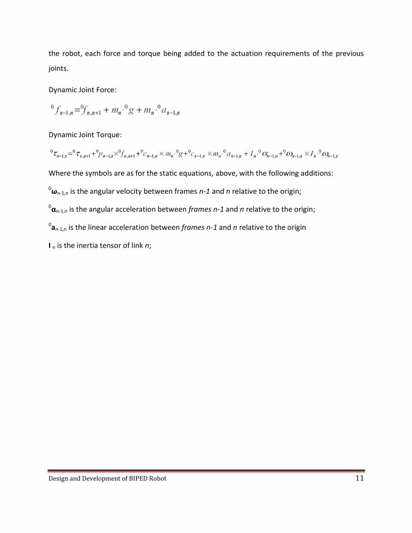
the robot, each force and torque being added to the actuation requirements of the previous
joints.
Dynamic Joint Force:
Dynamic Joint Torque:
Where the symbols are as for the static equations, above, with the following additions:
0ωn-1,n is the angular velocity between frames n-1 and n relative to the origin;
0αn-1,n is the angular acceleration between frames n-1 and n relative to the origin;
0an-1,n is the linear acceleration between frames n-1 and n relative to the origin
I n is the inertia tensor of link n;
Design and Development of BIPED Robot 12
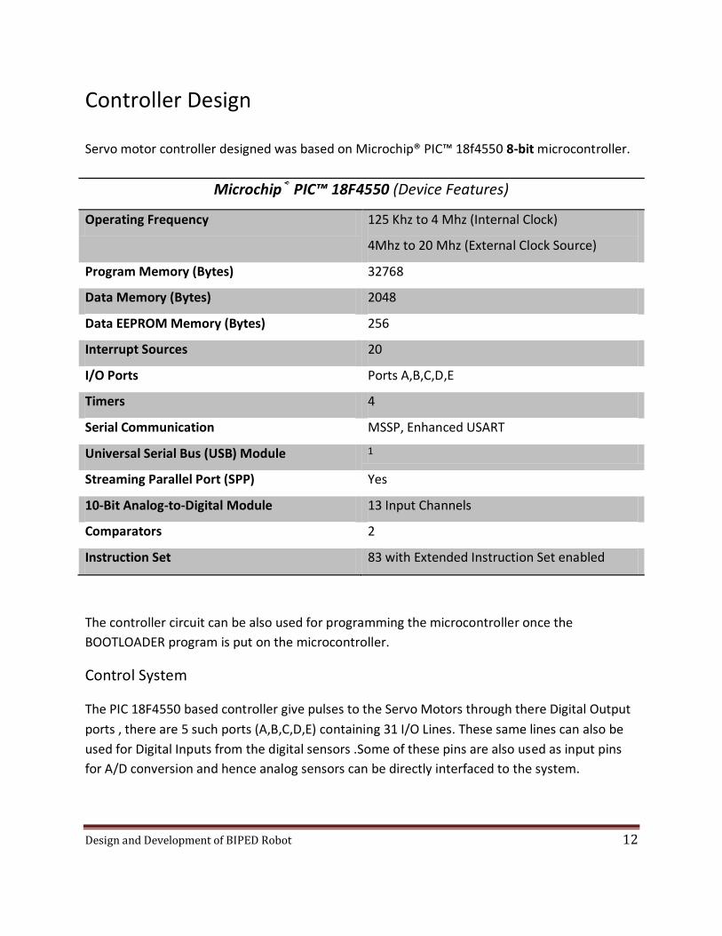
Controller Design
Servo motor controller designed was based on Microchip® PIC™ 18f4550 8-bit microcontroller.
Microchip® PIC™ 18F4550 (Device Features)
Operating Frequency 125 Khz to 4 Mhz (Internal Clock)
4Mhz to 20 Mhz (External Clock Source)
Program Memory (Bytes) 32768
Data Memory (Bytes) 2048
Data EEPROM Memory (Bytes) 256
Interrupt Sources 20
I/O Ports Ports A,B,C,D,E
Timers 4
Serial Communication MSSP, Enhanced USART
Universal Serial Bus (USB) Module 1
Streaming Parallel Port (SPP) Yes
10-Bit Analog-to-Digital Module 13 Input Channels
Comparators 2
Instruction Set 83 with Extended Instruction Set enabled
The controller circuit can be also used for programming the microcontroller once the
BOOTLOADER program is put on the microcontroller.
Control System
The PIC 18F4550 based controller give pulses to the Servo Motors through there Digital Output
ports , there are 5 such ports (A,B,C,D,E) containing 31 I/O Lines. These same lines can also be
used for Digital Inputs from the digital sensors .Some of these pins are also used as input pins
for A/D conversion and hence analog sensors can be directly interfaced to the system.

Design and Development of BIPED Robot 13
Based on the program in the microcontroller, the pulse width at the signal terminal of the servo
motor is controlled thereby controlling the rotation angle of the servo motor.
BIPED HARDWARE
Microchip® PIC™ 18f4550
Based Controller / USB Programmer
Board
DIGITAL OUTPUTS
ANALOG
INPUTS
( 13 A/D
Converters )
Pulses received by the
SERVO MOTORSANALOG SENSORSDIGITAL SENSORS
DIGITAL
INPUTS
HEX code generated from the C-source
code on HITEC- Hardware C Compiler
in the PC once the BOOTLOADER Code
provided by Microchip is written on the
Microcontroller
Programming through
USB PORT
BOOTLOADER Code by
Microchip on the PC
SERIAL Port
Serial Port JDM
Type Programmer
For
PIC18F4550
Design and Development of BIPED Robot 14
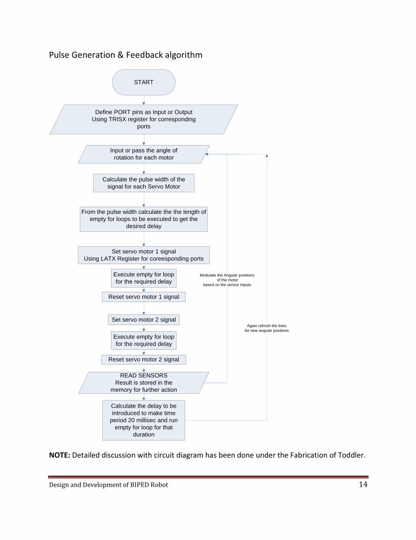
Pulse Generation & Feedback algorithm
START
Calculate the pulse width of the
signal for each Servo Motor
Input or pass the angle of
rotation for each motor
Define PORT pins as Input or Output
Using TRISX register for corresponding
ports
From the pulse width calculate the the length of
empty for loops to be executed to get the
desired delay
Set servo motor 1 signal
Using LATX Register for coreesponding ports
Execute empty for loop
for the required delay
Set servo motor 2 signal
Calculate the delay to be
introduced to make time
period 20 millisec and run
empty for loop for that
duration
Reset servo motor 1 signal
Reset servo motor 2 signal
Execute empty for loop
for the required delay
READ SENSORS
Result is stored in the
memory for further action
Again refresh the lines
for new angular positions
Modulate the Angular positions
of the motor
based on the sensor Inputs
NOTE: Detailed discussion with circuit diagram has been done under the Fabrication of Toddler.

Design and Development of BIPED Robot 15
12 Degre e of Freedom Biped Robot
Coordinate Configuration
The above figure shows the coordinate configuration of the 12 DOF biped. The method for
assignment is in accordance with Denavit Hartenberg Algorithm. Each joint is associated with a
coordinates system. The method for assignment is described below.
Link parameters
1. bk = Intersection of xk & zk-1 axes
2. θk = Angle of rotation from xk-1 to xk measured about zk-1.
3. dk = Distance from origin of frame Lk-1 to point bk measured along zk-1.
4. ak = Distance of point bk from the origin of frame Lk measured along xk.

Design and Development of BIPED Robot 16
5. αk = rotation of zk-1 to zk measured about xk

Design and Development of BIPED Robot 17
Coordinate transformation Basics
Let n-1An be the transformation from one coordinate system to the next coordinate system.
Hence, n-1An can be expressed as follows
It is Denavit-Hartenberg transformation of one link w.r.t. previous link
General Transformation of a coordinate frame w.r.t first frame = 0A1*0A2*…*0An
Denavit-Hartenberg Parameters for 12 Motor Biped Robot
S.No. Joint Angle
(θk)
Joint Distance
(Dk)
Link Length
(Ak)
Link Twist Angle
(αk)
1. 0 0 .02 0
2. 0 0 .04 -1.57075
3. 0 0 .057 0
4. 0 0 .057 0
5. 0 .0095 .022 1.57075
6. -1.57075 -.0095 0 -1.57075
7. 0 0 -.06 0
8. 0 0 0 1.57075
9. 1.57075 .0095 -.022 -1.57075
10. 0 .0095 -.057 0
11. 0 0 -.057 0
12. 0 0 -.04 1.57075
13. 0 0 -.02 0

Design and Development of BIPED Robot 18
Mechanical Design
Key features
Low weight: The Body should be as low weight as possible, so that the torque requirement of
the motors is low. Low torque motor directly means low cost.
Dual Ball Bearing Motors: The Body should vibrate as little as possible. Since the proper
working of biped requires balancing which is difficult to achieve in a vibrating body, hence the
joints should not be loose. For this we have chosen dual ball bearing motors. This means that
the motor will have shaft on both sides and hence support for the joint will be better.
Robustness: Bipeds should have high robustness as they have high probability of falling down.
Ease of fabrication and availability: For all the above reasons and this reason Aluminum sheet
(2mm thick) was chosen as fabrication material.
Design of Biped:
Foot Design:The foot shoot be made of some soft but tough material so that it can tolerate and
absorb repeated impacts made on ground. Rubber is ideal for this purpose
Dual Ball Bearing

Design and Development of BIPED Robot 19

Design and Development of BIPED Robot 20

Design and Development of BIPED Robot 21
Final Biped Design

Design and Development of BIPED Robot 22
Torque Simulation Results
Simulation Procedure:
Step 1: The Model of robot was realized on Solidworks.
Step 2: Each link was exported as a wrl file
Step 3: The links were reassembled in a VRML world.
Step 4: The world was dynamically animated using MATLAB.
Simulation Results:
Torque calculations were performed in MATLAB and plotted.

Design and Development of BIPED Robot 23
The whole walking phenomena can be divided into many phases.
Phase I: This is a double limb support phase. Motor 1 and motor 12 are used to move the centre
of mass of biped above the supporting leg.
Phase II: Single Limb support phase. Active leg is swung in this phase. Motor 8 is used to swing
the active leg. Motor 1 and motor 2 handle the balancing.
Phase III: Ground Active leg. This is again single limb support phase
Phase IV and Phase V: Change Active Leg. This is Double limb Support phase. The weight is
shifted from the one leg to the other.
Phase VI: Lift New Active Leg. This is Single Limb Support phase.
Phase VII: Swing Active New Leg.
The MATLAB code of simulation can be found in the Appendix.

Design and Development of BIPED Robot 24
4 Degree of Freedom Biped
Coordinate Configuration
Denavit-Hartenberg Parameters for 4 Motor Biped Robot
Joint Angle
(θk)
Joint Distance
(Dk)
Link Length
(Ak)
Link Twist
Angle (αk)
bi
0 0 0 0 .02
0 0 .0344 -90 0
0 0 .058 0 0
0 0 .0344 90 0
0 0 0 0 -.02

Design and Development of BIPED Robot 25
Mechanical Design of 4-Motor Biped
Foot design: The foot is required to support one motor and a bearing so that rest of the body
rests on these two joints stably. The sheet has been cut to reduce weight.
Foot

Design and Development of BIPED Robot 26
Foot with Motor and bearing attached
Right Hip Joint

Design and Development of BIPED Robot 27
Right Leg
Complete 4-Motor Biped Design

Design and Development of BIPED Robot 28
Torque Simulation Results
Phase I: Lifting Active Leg
Phase II: Swinging Active Leg
Phase III: Grounding Active Leg
Phase IV: Changing Active Leg(Double Limb Support Phase) and Lifting New Active leg
Phase V: Swinging New Active leg
Phase VI: Grounding Active Leg
Phase VII: Double Leg Support Phase

Design and Development of BIPED Robot 29
Actuators and Feedback
Servo Motor Futaba™ S3003 have been used as actuators.
FUTABA S3003 Voltage Input 6.0 V Stall Torque 4.1 kg-cm @ 6.0 V Speed 0.16 sec for 60 dergrees of rotation Gear Type Plastic Angular Span of rotation 180 degrees
Electrical Specifications Pulse width range 900 µsec to 1900 µsec Duty cycle 20 ms
Electrical Control of Servo motor:
Servos have a very simple electrical interface; they usually have 3 wires, Red for Vcc, Black for
GND and White for Signal. Once power ( 4.8 to 6.0 V) and ground is supplied to the servo, the
data wire is prepared to receive encoded signal in the form of pulse width modulation (PWM).
The dutycycle is of 20ms, and the pulse width or ON- time is 900 µsec to 1900 µsec.
Angular Position of the servo for
different pulse width

Design and Development of BIPED Robot 30
Servo Construction
RC servos are comprised of a DC motor mechanically linked to a potentiometer (Sensor). Pulse-
width modulation (PWM) signals sent to the servo are translated into position commands by
electronics inside the servo. When the servo is commanded to rotate, the DC motor is powered
until the potentiometer reaches the value corresponding to the commanded position.
The servo will move based on the pulses sent over the control wire, which set the angle of the
actuator arm. The servo expects a pulse every 20 ms in order to gain correct information about
the angle. The width of the servo pulse dictates the range of the servo's angular motion.
Potentiometer
DC Motor
Gear Box
Design and Development of BIPED Robot 31
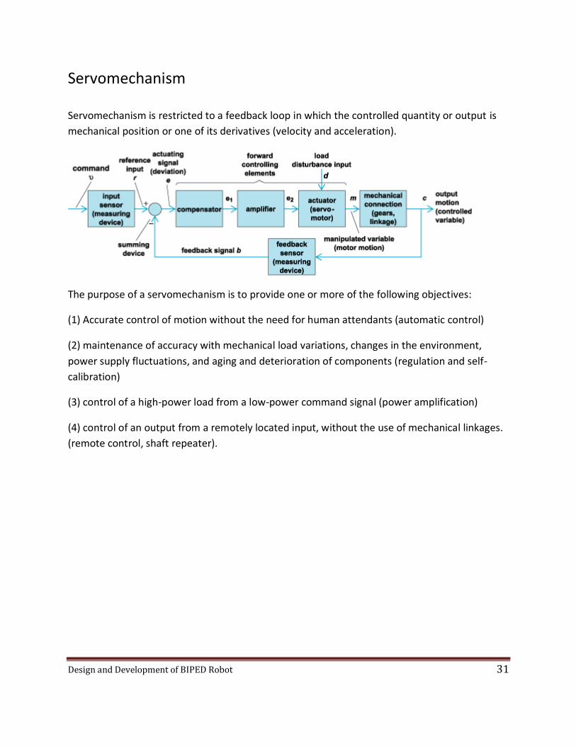
Servomechanism
Servomechanism is restricted to a feedback loop in which the controlled quantity or output is
mechanical position or one of its derivatives (velocity and acceleration).
The purpose of a servomechanism is to provide one or more of the following objectives:
(1) Accurate control of motion without the need for human attendants (automatic control)
(2) maintenance of accuracy with mechanical load variations, changes in the environment,
power supply fluctuations, and aging and deterioration of components (regulation and self-
calibration)
(3) control of a high-power load from a low-power command signal (power amplification)
(4) control of an output from a remotely located input, without the use of mechanical linkages.
(remote control, shaft repeater).

Design and Development of BIPED Robot 32
Controller/USB Programmer Board Circuit
Initially the PIC18F4550 chip is programmed through the serial port using a JDM type Serial
Programmer and WINPIC800 software and the propriety code BOOTLOAD.hex is programmed
into the device.
Once this process is over for programming the device the BOOT button is kept pressed (RB4 =0)
and RESET is pressed and released , then BOOT is released (RB4 =1).
Pin 2 (AN0) is programmed as the input to A/D converter module , this pin has Analog distance
sensor Sharp® GPD120 Analog Distance sensor.

Design and Development of BIPED Robot 33
Pin 4(RA2),5(RA3),6(RA4),9(RE1) are used as digital outputs i.e. they are connected to the signal
terminal of the servo motor and these digital output are programmed to provide PWM(Pulse
Width Modulated) signals.
An external supply 6.0 V is directly connected to the Motor Supply , where as microcontroller
Vdd is a regulated 5V (through a 7805 voltage regulator).
Reset signal resets the execution.
Power Connector
Analog Sensor
Servo Motor
Connection
PIC 18F4550
RESET
BOOT
GPD120 Sensor
USB Interface

Design and Development of BIPED Robot 34
Handling Inputs & Outputs
There are basically three types of signal on the port pins.
1. Digital Outputs
2. Digital Inputs
3. Analog Inputs
Digital Inputs/Outputs are through ports A,B,C,D,E
Each port has three registers for its operation. These registers are:
1. TRIS register (Data direction register) (1-Input 0-Output)
2. PORT register (reads the levels on the pins of the device)
3. LAT register (Output Latch)
Digital Outputs:
Set TRISX register bits
corresponding to digital outputs
as 1 & inputs as 0
Set LATX bits to put the digital
value on the port pins in output
mode.
Utilize the above digital value of
the port pin
Put new value on the port

Design and Development of BIPED Robot 35
Digital Inputs
Set TRISX register bits
corresponding to digital outputs
as 1 & inputs as 0
Read PORTX bits to get the
digital value on the port pins in
input mode.
Utilize the above digital value of
the port pin
Get new value from the port

Design and Development of BIPED Robot 36
Analog Inputs:
Set TRISX register bits as 0
Set ADCON0 (bit 5:2
(for corresponding A/D input
line)
Set ADCON0 (bit 0) as 1 for
enabling A/D module
Set ADCON1 (bit 3:0) such that
the corresponding pins are
configured as Analog
(from the datasheet)
Set ADCON1 (bit 5:4) for setting
reference analog voltage
Set ADCON2 (bit 7) for left or right
justified result mode
Set ADCON2 (bit 5:3) as 0 for
manual acquisition time setting
Set ADCON2 (bit 2:0) for setting A/
D module clock.
Settings over.
Now reading.
Set ADCON0 (bit 1) as 1
for starting the conversion
Check if ADCON0 (Bit 0)
== 0
NO, Wait till Conversion Completed
YES, read the next input channel

Design and Development of BIPED Robot 37
Analog inputs are read through A/D converter module. For setting a particular pin to analog
mode we set ADCON1(bit 3:0) or PCFG3:PCFG0 bits from the table.
Registers to be programmed for A/D Conversion are:
ADCON2

Design and Development of BIPED Robot 38
ADCON1
ADCON0

Design and Development of BIPED Robot 39
JDM Type Serial Programmer Circuit
The JDM programmer series are open-source programmer modules for PIC programming, the
version we used is JDM2 programmer for PIC 18F/16F/12F 20/28/40 pin Microcontrollers.
The serial port is used to produce the required 13V supply through an analog circuit for
programming the EEPROM of the microcontroller.
The Software used fro programming through the serial port is WINPIC800 which also is
available freely.

Design and Development of BIPED Robot 40
Hardware Operation
Toddler has a distance sensor attached to it which causes it to sense any obstacle in its path.
Whenever an obstacle appears it moves away from it either in left or right direction, by strafing.
Open Loop straight walking of Toddler can be divided into many steps.
Right leg angled ,push the ground
Right leg up
Right leg swing forward
Right leg leveled
Right leg down
Power On Start
Left leg angled ,push the ground
Left leg up
Left leg swing forward
Left leg leveled
Left leg down
Repeat for Continuous motion
Open Loop Straight Walking Sequence of Toddler(Without Sensor)
Design and Development of BIPED Robot 41
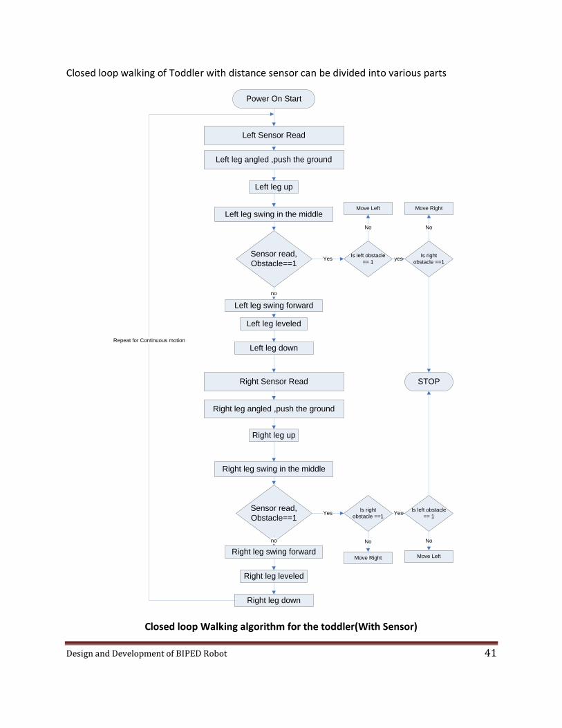
Closed loop walking of Toddler with distance sensor can be divided into various parts
Right leg angled ,push the ground
Right leg up
Right leg swing forward
Right leg leveled
Right leg down
Power On Start
Left leg angled ,push the ground
Left leg up
Left leg swing forward
Left leg leveled
Left leg downRepeat for Continuous motion
Left leg swing in the middle
Sensor read,
Obstacle==1
no
Right leg swing in the middle
Sensor read,
Obstacle==1
no
Is left obstacle
== 1
Is right
obstacle ==1
Left Sensor Read
Right Sensor Read
Yes
Yes
Move Left
Is right
obstacle ==1
Is left obstacle
== 1
Move Right
No
No
yes
Move Right
No
Move Left
No
Yes
STOP
Closed loop Walking algorithm for the toddler(With Sensor)

Design and Development of BIPED Robot 42
Sensor Description:
Sensor used is Distance sensor Sharp® GPD120 Distance sensor.
This sensor is based on the measurement of angle of incoming signal to determine the distance
(for details read datasheet), hence it produces very reliable results for various types of surfaces.
From the Datasheet
.- White Paper (reflection ratio 90%)
x- Gray paper (reflection ratio 18%)

Design and Development of BIPED Robot 43
Requirements
Software Requirements
1. Operating System : Windows XP
2. Matlab 7.0 (Virtual reality tool box)
3. Solid Works 2004
4. MPLab IDE 8.0
5. Microchip C18 compiler (v3.12 Student Edition)
6. Oshonsoft PIC18 simulator IDE (Evaluation Copy) v2.55
7. WinPic800 serial programmer interface
8. USB Demonstration board bootloader & programmer
Hardware Requirements
1. Power Supply 6.0 V / 4A
2. USB & Serial Port Enabled Computer
3. JDM Serial Programmer

Design and Development of BIPED Robot 44
Cost Estimation
Part No.
Component Name Quantity Cost (Rs.)
1. Servo Motor (FUTABA® S3003) 4 3000
2. Microchip® PIC™ 18F4550 1 250
3. Sharp® GPD120 Distance Sensor 1 950
4. Aluminium Sheet 1ftx1ft 30 5. Circuit Elements & connectors 100
Total Cost of Hardware =Rs. 4330
Design and Development of BIPED Robot 45
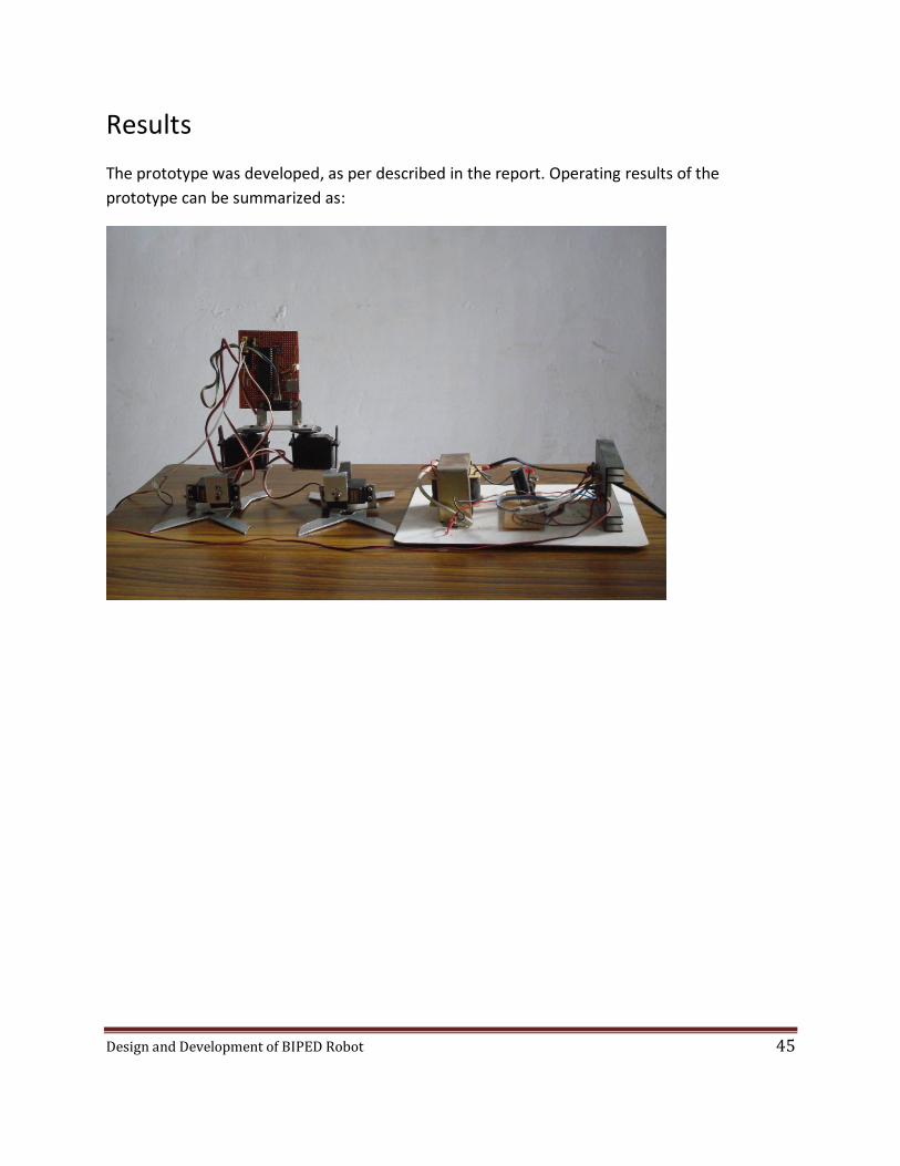
Results
The prototype was developed, as per described in the report. Operating results of the
prototype can be summarized as:

Design and Development of BIPED Robot 46
1) Sequences of angular movement for a step as performed by the robot.
a) Right Leg Step

Design and Development of BIPED Robot 47
b) Left leg step

Design and Development of BIPED Robot 48
2) Average Step time 8.00 seconds
3) Turning time 3.25 seconds
4) Motor Control Pulse Simulation (On a third party simulator)
Simulation is done in PIC18 simulator IDE (Evaluation Copy) v2.55
It is a user-friendly graphical development environment serving PIC18 developers, producing
reliable results. It is also certified by Microchip.
Design and Development of BIPED Robot 49
Future Aspects
The 4-degree of freedom (DOF) biped is almost useless for any kind of practical jobs. So the
degrees of freedom of biped are required to be increased to atleast 10. Though, for the
purpose of study only 4-DOF is a good option.
The present prototype can be integrated with different feedback sensors used in bipeds for the
purpose of balancing even on uneven terrain. These include Pressure sensors and
accelerometers. Accelerometers are used as body inclination sensors which makes them quite
useless for current prototype, as it variable inclination of the supported body is a part of gait of
the biped.
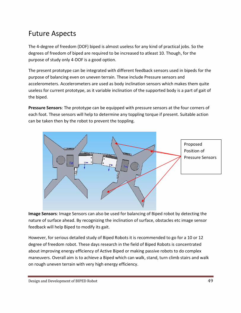
Pressure Sensors: The prototype can be equipped with pressure sensors at the four corners of
each foot. These sensors will help to determine any toppling torque if present. Suitable action
can be taken then by the robot to prevent the toppling.
Image Sensors: Image Sensors can also be used for balancing of Biped robot by detecting the
nature of surface ahead. By recognizing the inclination of surface, obstacles etc image sensor
feedback will help Biped to modify its gait.
However, for serious detailed study of Biped Robots it is recommended to go for a 10 or 12
degree of freedom robot. These days research in the field of Biped Robots is concentrated
about improving energy efficiency of Active Biped or making passive robots to do complex
maneuvers. Overall aim is to achieve a Biped which can walk, stand, turn climb stairs and walk
on rough uneven terrain with very high energy efficiency.
Proposed
Position of
Pressure Sensors

Design and Development of BIPED Robot 50
References
1. Help file of Spacelib Robotic simulation library for Matlab© G.Lignani C. Moiola 1998
2. Matlab 7.0 Documentation by Mathworks Inc.
3. Solid Works 2004 Documentation by Solidworks Corp.
4. Datasheet for PIC18F2455/2550/4455/4550 family by Microchip Technology Inc.
5. Datasheet for GPD2S120 Sensor by Sharp Technologies.
6. IEEE Automation & Robotics Magazine, June 2007
7. The Development of Honda Humanoid Robot by Kazuo Hirai, Masato Hirose, Yuji
Haikawa, Toru Takenaka from Honda R&D Co., Ltd.
8. Towards Efficient Biped Robots by Filipe M. Silva , J.A. Tenreiro Machado
9. Development of a Bipedal Humanoid Robot Control Method of Whole Body Cooperative
dynamic Biped Walking by Jin’ichi Yamaguchi,Eiji Soga, Sadatoshi Inoue and Atsuo
Takanishi
10. Towards the Design of a Biped Jogging Robot by M. Gienger, K. Loffler, F. Pfeiffer 11. http://www.Michochip.com 12. http://www.microchipc.com 13. http://pic18f.online.fr 14. http://www.microelektronika.com/ 15. http://www.beyondlogic.com/ 16. http://www.asimo.honda.com/ 17. http://www.yes-tele.com/ 18. http://www.semis.demon.co.uk/uJDM/uJDMmain.htm

Design and Development of BIPED Robot 51
Appendix
1) How to program Microchip® PIC ™18F4550. 2) Matlab code for Torque calculation & simulation of 12- DOF biped robot 3) Matlab code for Torque calculation & simulation of 4-DOF biped robot 4) Final C-Source Code for Feedback controlled biped robot.
How to Program Microchip® PIC ™18F4550.
Step 0:
Build the JDM2 Serial Programmer.
Step 1:
Build USB development board based on a PIC18F4550
Requirement around the PIC:
A 20MHz crystal oscillator & the two 15 or 22pF associated capacitors.
An USB-B connector powering the PIC (Vss & Vdd) and linked to D- & D+ pins.
a 'decoupling' capacitor between Vss & Vdd (100nF )
a 'decoupling' capacitor between Vss & Vusb (220nF min, 470nF is also good)
a button/switch S1 for hard reset on MCLR'
A button/switch S2 for entering in Boot mode on RB4.
Optional ICSP, LVP or ICD connector.
Step 2:
Install needed software, get Boot Firmware Source Code & PDFSUSB utility
Microchip MPLAB 7.00+ available from http://www.microchip.com/ide/
Microchip C18 2.40+ Student Ed from http://www.microchip.com/c18/
Microchip USB Boot loader files

Design and Development of BIPED Robot 52
Step 3:
Edit the Boot project & generate a complete HEX file
Launch MPLAB, then Menu: Project/Open : "C:\MCHPFSUSB\fw\Boot\MCHPUSB.mcp"
Step 4:
Program this boot firmware in the PIC
Write the firmware code in a PIC using WINPIC800 and JDM2 programmer compatible with
PIC18F4550.
Step 5:
Connect USB & 1st boot load detection
Connect the USB cable. It powers the PIC (not visible at this time).
Enter Boot Mode by holding down enter boot and then pressing S1 reset.
Windows will start detecting a new USB unknown device.
Step 6:
Manually specify Microchip "PIC18F4550 Family Device" INF driver to MS Windows
C:\MCHPFSUSB\Pc\MCHPUSB Driver\Release\
It should be recognized as "PIC18F4550 Family Device".

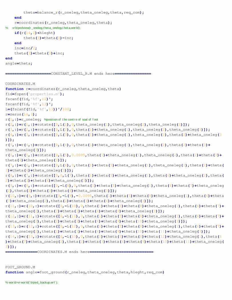
Code for simulation of 12-motor bipedWALKING2.m needs following files for execution1. AXIS.M2. BALANCE_R.M3. CENTRE_MASS.M4. CONST_LEVEL_R.M5. COORDINATES.M6. FOOT_GROUND.M7. PROPERTIES.M8. ROTATE.M9. STALL_TORQUE.M10. SHIFT_WEIGHT.M11. VRBIPEDVIEW.M
WALKING2.Mfunction walking2()
%DEPENDENCIES:%balance_left, vrbipedview, const_level,stal torque, const_level_r,% balance_left_r,coordinates,centre_mass,rotate, properties, axis,% foot_ground, shift_weight
theta=zeros(1,12);step_no=1;SCALE=20;SWING_MAX=pi/6;HIEGHT=0.025;fid=fopen('properties.m');fidw=fopen('theta.mot','w');fscanf(fid,'%f',40);lbh=fscanf(fid,'%f',3)'/100;fclose(fid);world=vrworld('biped.wrl');open(world);view(world);theta_oneleg=[0 0 0];r_oneleg=[0 0 0];vrbipedview(r_oneleg,theta_oneleg,theta,world);pause(.5);
%phase 1%================shifting balance from both feet to left foot(1-4)==========
%___________________Changing View Point___________Rv=0.6325;tvi=0.3218;tvf=1.57075;yv=0.15;xv=Rv*sin(tvf);zv=Rv*cos(tvf);world.vpoint.position=[xv,yv,zv];world.vpoint.orientation=[0,1,0,tvf];
Matlab code for Torque calculation & simulation of 12- DOF biped robot

%approx required angle for balance at left foot----------------------thetai=theta;thetaf=balance_r(r_oneleg,theta_oneleg,theta,[0 0 0]);for i=1:4
theta=thetai+(thetaf-thetai)*i/4;theta(12)=-theta(1);theta(5)=-theta(1);theta(8)=theta(1);%right foot must help in obtaing that positionfprintf(fidw,'%f ',theta);fprintf(fidw,'\n');vrbipedview(r_oneleg,theta_oneleg,theta,world);pause(.2)y(step_no,:)=stall_torque(r_oneleg,theta_oneleg,theta);step_no=step_no+1;
end%================== LIFT ACTIVE LEG(5-9)===================%==================SINGLE LIMB SUPPORT PHASE==========%==================SWING ACTIVE LEG====================%weight on left foot%motor 8 is rotated to put the right foot forward, motor 1,2 take care of%balancing%___________________Changing View Point___________Rv=0.6325;tvi=1.57075;tvf=0;yv=0.15;% Rv=sqrt(7.2*7.2+20*20);% tvi=1.57075;% tvf=0;% yv=5.6;for i=1:5
tv=tvi+(tvf-tvi)*i/5;xv=Rv*sin(tv);zv=Rv*cos(tv);world.vpoint.position=[xv,yv,zv];world.vpoint.orientation=[0,1,0,tv];pause(.1);
end%________________Changed________________________for i=1:5
theta(9)=i*SWING_MAX/5;theta=const_level_r(r_oneleg,theta_oneleg,theta,HIEGHT,[0 0 0]);fprintf(fidw,'%f ',theta);fprintf(fidw,'\n');vrbipedview(r_oneleg,theta_oneleg,theta,world);pause(.4)y(step_no,:)=stall_torque(r_oneleg,theta_oneleg,theta);step_no=step_no+1;
end
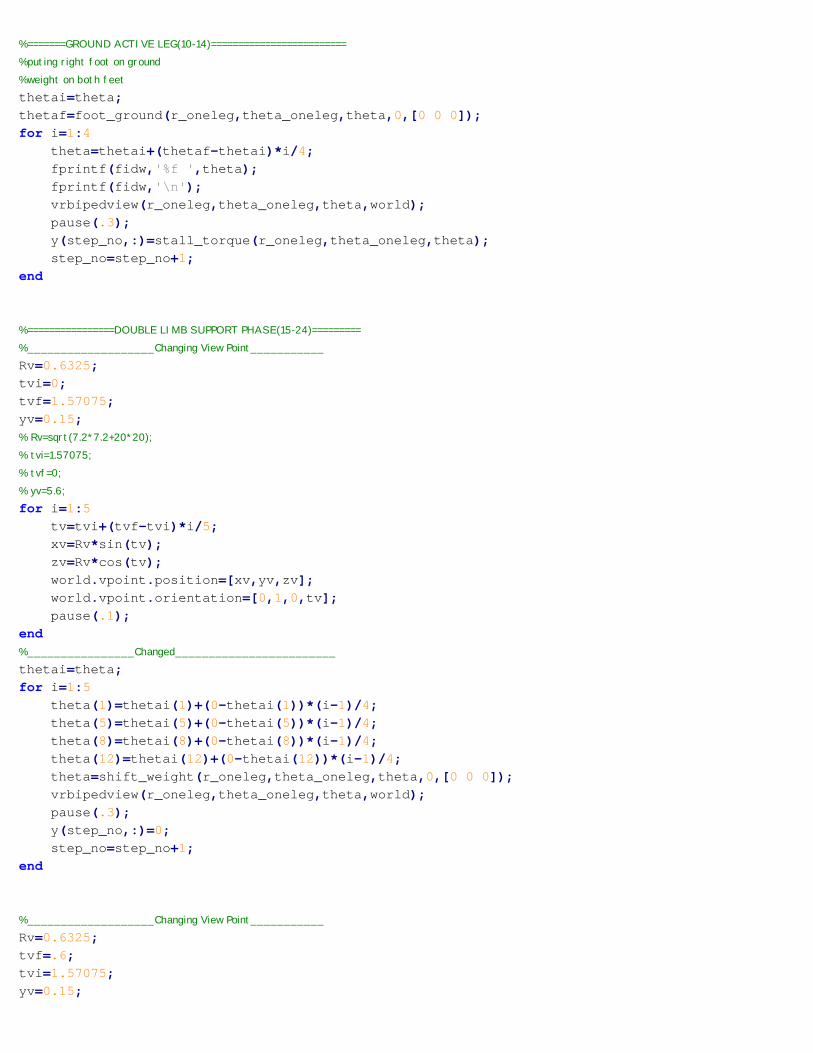
%=======GROUND ACTIVE LEG(10-14)=========================%puting right foot on ground %weight on both feetthetai=theta;thetaf=foot_ground(r_oneleg,theta_oneleg,theta,0,[0 0 0]);for i=1:4
theta=thetai+(thetaf-thetai)*i/4;fprintf(fidw,'%f ',theta);fprintf(fidw,'\n');vrbipedview(r_oneleg,theta_oneleg,theta,world);pause(.3);y(step_no,:)=stall_torque(r_oneleg,theta_oneleg,theta);step_no=step_no+1;
end
%================DOUBLE LIMB SUPPORT PHASE(15-24)=========%___________________Changing View Point___________Rv=0.6325;tvi=0;tvf=1.57075;yv=0.15;% Rv=sqrt(7.2*7.2+20*20);% tvi=1.57075;% tvf=0;% yv=5.6;for i=1:5
tv=tvi+(tvf-tvi)*i/5;xv=Rv*sin(tv);zv=Rv*cos(tv);world.vpoint.position=[xv,yv,zv];world.vpoint.orientation=[0,1,0,tv];pause(.1);
end%________________Changed________________________thetai=theta;for i=1:5
theta(1)=thetai(1)+(0-thetai(1))*(i-1)/4;theta(5)=thetai(5)+(0-thetai(5))*(i-1)/4;theta(8)=thetai(8)+(0-thetai(8))*(i-1)/4;theta(12)=thetai(12)+(0-thetai(12))*(i-1)/4;theta=shift_weight(r_oneleg,theta_oneleg,theta,0,[0 0 0]);vrbipedview(r_oneleg,theta_oneleg,theta,world);pause(.3);y(step_no,:)=0;step_no=step_no+1;
end
%___________________Changing View Point___________Rv=0.6325;tvf=.6;tvi=1.57075;yv=0.15;

% Rv=sqrt(7.2*7.2+20*20);% tvi=1.57075;% tvf=0;% yv=5.6;for i=1:5
tv=tvi+(tvf-tvi)*i/5;xv=Rv*sin(tv);zv=Rv*cos(tv);world.vpoint.position=[xv,yv,zv];world.vpoint.orientation=[0,1,0,tv];pause(.1);
end%________________Changed________________________thetai=theta;for i=1:5
xi=2*sin(-thetai(11));xf=-sin(thetai(3)+thetai(2))+sin(-thetai(2));x0=2*sin(-thetai(11))-sin(thetai(3)+thetai(2))+sin(-thetai(2));x=xi+(xf-xi)*i/5;Y=cos(thetai(2))+cos(thetai(3)+thetai(2));X=x-x0;theta(3)=acos((X*X+Y*Y-2)/2);A=1+cos(theta(3));B=sin(theta(3));theta(2)=atan((A*X-B*Y)/(A*Y+B*X));theta(4)=-theta(3)-theta(2);theta(10)=-acos((x*x+Y*Y-2)/2);a=1+cos(theta(10));b=sin(theta(10));theta(9)=atan((a*x-b*Y)/(a*Y+b*x));theta(11)=-theta(10)-theta(9);r=coordinates(r_oneleg,theta_oneleg,theta);vrbipedview(r_oneleg,theta_oneleg,theta,world);pause(.3);y(step_no,:)=0;step_no=step_no+1;
endtheta(2)=-pi/6;theta(3)=0;theta(4)=pi/6;
%=================CHANGE ACTIVE LEG(24-29)===============r=coordinates(r_oneleg,theta_oneleg,theta);r_right=r(14,:);thetai=theta;angle=theta(12:-1:1);angle=balance_r([0 0 0],theta_oneleg,angle,[0 0 0]);thetaf=angle(12:-1:1);thetaf(12)=-thetaf(1);thetaf(5)=-thetaf(1);thetaf(8)=thetaf(1);thetaf(9)=-thetaf(10)-thetaf(11);for i=1:5

theta=thetai+(thetaf-thetai)*i/5;r=coordinates([0 0 0],theta_oneleg,theta);r_oneleg=r_right-r(14,:)+[-0.01,.008,0];
vrbipedview(r_oneleg,theta_oneleg,theta,world);pause(.3);angle=theta(12:-1:1);tor=stall_torque(r_oneleg,theta_oneleg,angle);y(step_no,:)=tor(12:-1:1);step_no=step_no+1;
end
%==================LIFT ACTIVE LEG(30-34)=========for i=1:5
theta(10)=thetaf(10)*(5-i)/5;angle=theta(12:-1:1);angle=balance_r([0 0 0],theta_oneleg,angle,[0 0 0]);theta=angle(12:-1:1);theta(1)=-theta(12);theta(5)=-theta(1);theta(8)=theta(1);theta(9)=-theta(10)-theta(11);r=coordinates([0 0 0],theta_oneleg,theta);r_oneleg=r_right-r(14,:)+[-.01 .008 0];vrbipedview(r_oneleg,theta_oneleg,theta,world);pause(.3);angle=theta(12:-1:1);tor=stall_torque(r_oneleg,theta_oneleg,angle);y(step_no,:)=tor(12:-1:1);step_no=step_no+1;
end
% %================SWING ACTIVE LEG(35-39)======================thetai=theta;for i=1:5
theta(4)=thetai(4)+(-SWING_MAX-thetai(4))*i/5;theta(2)=-theta(4);angle=theta(12:-1:1);angle=balance_r([0 0 0],theta_oneleg,angle,[0 0 0]);theta=angle(12:-1:1);theta(9)=-theta(10)-theta(11);theta(1)=-theta(12);theta(5)=-theta(1);theta(8)=theta(1);r=coordinates([0 0 0],theta_oneleg,theta);r_oneleg=r_right-r(14,:)+[-.01 .008 0];vrbipedview(r_oneleg,theta_oneleg,theta,world);pause(.3);angle=theta(12:-1:1);tor=stall_torque(r_oneleg,theta_oneleg,angle);y(step_no,:)=tor(12:-1:1);step_no=step_no+1;
endhold;

c=['b','g','r','c','m','y','k','.','o','x','+','*'];for i=1:12
plot(1:(step_no-1),abs(y(:,i)),c(i));endhold;================WALKING2.M ENDS HERE==========================AXIS.Mfunction axis=axis(theta,theta_oneleg)%left foot on ground motor 1 axisaxis=zeros(12,3);axis(1,:)=rotate([1,0,0,theta_oneleg(1),theta_oneleg(2),theta_oneleg(3)]);axis(2,:)=rotate([0,0,1,theta(1)+theta_oneleg(1),theta_oneleg(2),theta_oneleg(3)]);axis(3,:)=rotate([0,0,1,theta(1)+theta_oneleg(1),theta_oneleg(2),theta(2)+theta_oneleg(3)]);axis(4,:)=rotate([0,0,1,theta(1)+theta_oneleg(1),theta_oneleg(2),theta(2)+theta(3)+theta_oneleg(3)]);axis(5,:)=rotate([1,0,0,theta(1)+theta_oneleg(1),theta_oneleg(2),theta(2)+theta(3)+theta(4)+theta_oneleg(3)]);axis(6,:)=rotate([0,1,0,theta(1)+theta(5)+theta_oneleg(1),theta_oneleg(2),theta(2)+theta(3)+theta(4)+theta_oneleg(3)]);axis(7,:)=rotate([0,1,0,theta(1)+theta(5)+theta_oneleg(1),theta(6)+theta_oneleg(2),theta(2)+theta(3)+theta(4)+theta_oneleg(3)]);axis(8,:)=rotate([1,0,0,theta(1)+theta(5)+theta_oneleg(1),theta(6)+theta(7)+theta_oneleg(2),theta(2)+theta(3)+theta(4)+theta_oneleg(3)]);axis(9,:)=rotate([0,0,1,theta(1)+theta(5)+theta(8)+theta_oneleg(1),theta(6)+theta(7)+theta_oneleg(2),theta(2)+theta(3)+theta(4)+theta_oneleg(3)]);axis(10,:)=rotate([0,0,1,theta(1)+theta(5)+theta(8)+theta_oneleg(1),theta(6)+theta(7)+theta_oneleg(2),theta(2)+theta(3)+theta(4)+theta(9)+theta_oneleg(3)]);axis(11,:)=rotate([0,0,1,theta(1)+theta(5)+theta(8)+theta_oneleg(1),theta(6)+theta(7)+theta_oneleg(2),theta(2)+theta(3)+theta(4)+theta(9)+theta(10)+theta_oneleg(3)]);axis(12,:)=rotate([1,0,0,theta(1)+theta(5)+theta(8)+theta_oneleg(1),theta(6)+theta(7)+theta_oneleg(2),theta(2)+theta(3)+theta(4)+theta(9)+theta(10)+theta(11)+theta_oneleg(3)]);
==============AXIS.M ends here====================================
BALANCE_R.Mfunction angle=balance_r(r_oneleg,theta_oneleg,theta,req_com)inc=pi/2;angle=theta;angle(1)=0;angle(2)=0;%successive approximations upto pi/1024 radiansfor i=1:10
com=centre_mass(r_oneleg,theta_oneleg,angle,2);if (com(3,1)-req_com(1)<=0)
angle(2)=angle(2)-inc;endinc=inc/2;angle(2)=angle(2)+inc;
endinc=pi/2;for i=1:10
com=centre_mass(r_oneleg,theta_oneleg,angle,1);if (com(3,3)-req_com(3)>=0)
angle(1)=angle(1)-inc;

endinc=inc/2;angle(1)=angle(1)+inc;
end========================BALANCE_R.M===========================
CENTRE_MASS.Mfunction com=centre_mass(r_oneleg,theta_oneleg,theta,n)fid=fopen('properties.m');M=ones(1,14);M(2:13)=(fscanf(fid,'%f',12))';M_rods=(fscanf(fid,'%f',13))';L=(fscanf(fid,'%f',13))'/100;temp=fscanf(fid,'%f',2);M(1)=temp(1);M(14)=temp(2);r=zeros(12,3);M=M/1000;M_rods=M_rods/1000;r=coordinates(r_oneleg,theta_oneleg,theta);num=0;den=0;for i=1:n
%centre of mass left num=num+r(i,:)*M(i)+(r(i,:)+r(i+1,:))*M_rods(i)/2;den=den+M(i)+M_rods(i);
endcom=zeros(3,3);com(1,:)=num/den;numr=0;denr=0;for i=n+1:13
%centre of mass rightnumr=numr+r(i+1,:).*M(i+1)+(r(i,:)+r(i+1,:)).*M_rods(i)/2;denr=denr+M(i+1)+M_rods(i);
endcom(2,:)=numr/denr;com(3,:)=(num+numr+r(n+1).*M(n+1))/(den+denr+M(n+1));
====================CENTRE_MASS.M=============================
CONSTANT_LEVEL_R.Mfunction angle=const_level_r(r_oneleg,theta_oneleg,theta,hieght,req_com)
% world=vrworld('biped_backup.wrl');theta(3)=pi/2;inc=pi/2;for i=1:10
theta(4)=-theta(3)-theta(2);theta(12)=-theta(1); %to keep right foot flat along X-axistheta(11)=-theta(2)-theta(3)-theta(4)-theta(9);%to keep right foot flat along Z-axisif i>2
theta=balance_r(r_oneleg,theta_oneleg,theta,req_com);endr=coordinates(r_oneleg,theta_oneleg,theta);
% vrbipedview(r_oneleg,theta_oneleg,theta,world);if(r(14,2)<hieght)
theta(3)=theta(3)-inc;endinc=inc/2;theta(3)=theta(3)+inc;
endangle=theta;
====================CONSTANT_LEVEL_R.M ends here================
COORDINATES.Mfunction r=coordinates(r_oneleg,theta_oneleg,theta)fid=fopen('properties.m');fscanf(fid,'%f',12)';fscanf(fid,'%f',13)';L=(fscanf(fid,'%f',13))'/100;r=zeros(14,3);r(1,:)=r_oneleg; %position of the centre of soal of footr(2,:)=r(1,:)+rotate([0,L(1),0,theta_oneleg(1),theta_oneleg(2),theta_oneleg(3)]);r(3,:)=r(2,:)+rotate([0,L(2),0,theta(1)+theta_oneleg(1),theta_oneleg(2),theta_oneleg(3)]);r(4,:)=r(3,:)+rotate([0,L(3),0,theta(1)+theta_oneleg(1),theta_oneleg(2),theta(2)+theta_oneleg(3)]);r(5,:)=r(4,:)+rotate([0,L(4),0,theta(1)+theta_oneleg(1),theta_oneleg(2),theta(2)+theta(3)+theta_oneleg(3)]);r(6,:)=r(5,:)+rotate([0,L(5),0.0095,theta(1)+theta_oneleg(1),theta_oneleg(2),theta(2)+theta(3)+theta(4)+theta_oneleg(3)]);r(7,:)=r(6,:)+rotate([0,L(6),0,theta(1)+theta(5)+theta_oneleg(1),theta_oneleg(2),theta(2)+theta(3)+theta(4)+theta_oneleg(3)]);r(8,:)=r(7,:)+rotate([0,0,L(7),theta(1)+theta(5)+theta_oneleg(1),theta(6)+theta_oneleg(2),theta(2)+theta(3)+theta(4)+theta_oneleg(3)]);r(9,:)=r(8,:)+rotate([0,-L(8),0,theta(1)+theta(5)+theta_oneleg(1),theta(6)+theta(7)+theta_oneleg(2),theta(2)+theta(3)+theta(4)+theta_oneleg(3)]);r(10,:)=r(9,:)+rotate([0,-L(9),-0.0095,theta(1)+theta(5)+theta(8)+theta_oneleg(1),theta(6)+theta(7)+theta_oneleg(2),theta(2)+theta(3)+theta(4)+theta_oneleg(3)]);r(11,:)=r(10,:)+rotate([0,-L(10),0,theta(1)+theta(5)+theta(8)+theta_oneleg(1),theta(6)+theta(7)+theta_oneleg(2),theta(2)+theta(3)+theta(4)+theta(9)+theta_oneleg(3)]);r(12,:)=r(11,:)+rotate([0,-L(11),0,theta(1)+theta(5)+theta(8)+theta_oneleg(1),theta(6)+theta(7)+theta_oneleg(2),theta(2)+theta(3)+theta(4)+theta(9)+theta(10)+theta_oneleg(3)]);r(13,:)=r(12,:)+rotate([0,-L(12),0,theta(1)+theta(5)+theta(8)+theta_oneleg(1),theta(6)+theta(7)+theta_oneleg(2),theta(2)+theta(3)+theta(4)+theta(9)+theta(10)+theta(11)+theta_oneleg(3)]);r(14,:)=r(13,:)+rotate([0,-L(13),0,theta(1)+theta(5)+theta(8)+theta(12)+theta_oneleg(1),theta(6)+theta(7)+theta_oneleg(2),theta(2)+theta(3)+theta(4)+theta(9)+theta(10)+theta(11)+theta_oneleg(3)]);==============COORDINATES.M ends here============================
FOOT_GROUND.Mfunction angle=foot_ground(r_oneleg,theta_oneleg,theta,hieght,req_com)
% world=vrworld('biped_backup.wrl');

theta(3)=pi/2;inc=pi/2;for i=1:10
theta(4)=-theta(3)-theta(2);theta(12)=-theta(1); %to keep right foot flat along X-axistheta(11)=-theta(2)-theta(3)-theta(4)-theta(9);%to keep right foot flat along Z-axisif i>1
theta=balance_r(r_oneleg,theta_oneleg,theta,req_com);endr=coordinates(r_oneleg,theta_oneleg,theta);
% vrbipedview(r_oneleg,theta_oneleg,theta,world);if(r(14,2)<hieght)
theta(3)=theta(3)-inc;endinc=inc/2;theta(3)=theta(3)+inc;
endangle=theta;===================FOOT_GROUND.M ends here======================
PROPERIES.M59.8 59.8 59.8 59.8 59.8 59.8 59.8 59.8 59.8 59.8 59.8 59.8.1 20 21.4 21.4 17.25 10 8 10 17.25 21.4 21.4 20 .102 04 05.7 05.7 02.2 04.35 06 4.35 02.2 05.7 05.7 04 0245 4507.7 5 0.810 10 24 24 24 10 10 24 24 24 10 1045 45 45 45 45 45 45 45 45 45 45 45%------------FORMAT OF ABOVE ENTRIES-----------------%mass of 12 motors from leftank1 to gait and then to right ank1 in gms_____________________________________%mass of 13 linking rods left foot,ankle, leg, thigh .... gait... right%leg, right ankle,right foot in gms_____________________________________%length of the above rods or more approprately distance between centre of%masses of assumed point masses in cms_____________________________________%mass of 2 soals left then rightin gms____%length breadth of 2 motors____%max torques of the 12 motors in kg-cm____________________________________%damping constant of 12 joints in Newtons/(rad/s)================PROPERTIES.M ends here============================
ROTATE.Mfunction ans=rotate(input)% axis rotate about x,y,z respectively%cosider rotation to be acoording to right hand thumb ruler=input(1:3);thetax=-input(4);thetay=-input(5);

thetaz=-input(6);Ax=[1,0,0;0,cos(thetax),sin(thetax);0,-sin(thetax),cos(thetax)];Ay=[cos(thetay),0,-sin(thetay);0,1,0;sin(thetay),0,cos(thetay)];Az=[cos(thetaz),sin(thetaz),0;-sin(thetaz),cos(thetaz),0;0,0,1];
ans=(Ax*Ay*Az*r')';================ROTATE.M ends here===============================
SHIFT_WEIGHT.Mfunction angle=shift_weight(r_oneleg,theta_oneleg,theta,hieght,req_com)theta(3)=pi/2;inc=pi/2;for i=1:10
theta(4)=-theta(3)-theta(2);theta(12)=-theta(1); %to keep right foot flat along X-axistheta(11)=-theta(2)-theta(3)-theta(4)-theta(9);%to keep right foot flat along Z-axisr=coordinates(r_oneleg,theta_oneleg,theta);
% vrbipedview(r_oneleg,theta_oneleg,theta,world);if(r(14,2)<hieght)
theta(3)=theta(3)-inc;endinc=inc/2;theta(3)=theta(3)+inc;
endangle=theta;========================SHIFT_WEIGHT.M ends here=================
STALL_TORQUE.Mfunction tor=stall_torque(r_oneleg,theta_oneleg,theta)G=9.8;fid=fopen('properties.m');M=ones(1,14);M(2:13)=(fscanf(fid,'%f',12))';M_rods=(fscanf(fid,'%f',13))';L=(fscanf(fid,'%f',13))';temp=fscanf(fid,'%f',2);M(1)=temp(1);M(14)=temp(2);r=zeros(12,3);M=M/1000;M_rods=M_rods/1000;L=L/100;
r=coordinates(r_oneleg,theta_oneleg,theta);tor=zeros(1,12);torv=zeros(12,3);ax=axis(theta,theta_oneleg);for n=1:12
numr=zeros(1,3);denr=0;for i=n+1:13
%centre of mass rightnumr=numr+r(i+1,:).*M(i+1)+(r(i,:)+r(i+1,:)).*M_rods(i)/2;denr=denr+M(i+1)+M_rods(i);
end

com=numr/denr;torv(n,:)=cross(com-r(n+1,:),[0,denr*G,0]);tor(n)=(dot(torv(n,:),ax(n,:)));
end======================STALL_TORQUE.M ends here===================VRBIPEDVIEW.Mfunction vrbipedview(r_oneleg,theta_oneleg,theta,world)% SCALE=20;SCALE=1;mag=sqrt(dot(theta_oneleg,theta_oneleg));world.oneleg.translation=r_oneleg*SCALE;world.oneleg.rotation=[theta_oneleg(1),theta_oneleg(2),theta_oneleg(3),mag];world.ankle.rotation=[1,0,0,theta(1)];world.leg.rotation=[0,0,1,theta(2)];world.thigh.rotation=[0,0,1,theta(3)];world.hip1.rotation=[0,0,1,theta(4)];world.hip2.rotation=[1,0,0,theta(5)];world.gait.rotation=[0,1,0,theta(6)];world.hip2r.rotation=[0,1,0,theta(7)];world.hip1r.rotation=[1,0,0,theta(8)];world.thighr.rotation=[0,0,1,theta(9)];world.legr.rotation=[0,0,1,theta(10)];world.ankler.rotation=[0,0,1,theta(11)];world.footr.rotation=[1,0,0,theta(12)];==================VRBIPEDVIEW.M ends here========================

function mainclcstring0=input('Digit the name of VRML FILE(d for deafault): ','s');if string0=='d'
string0='toddler.wrl';string1='toddler.DATA';string2='toddler.OUT';
elsestring1=input('Digit the DATA FILE: ','s');string2=input('Digit the OUTPUT FILE (S=Screen): ','s');
end
vrmlworld=vrworld(string0);open(vrmlworld);view(vrmlworld);
data=fopen(string1,'r');if (data==-1)
error('Error in ROB_MAT, unable to open DATA FILE ')end
string2=upper(string2); % uppercase;if (string2=='S')
out=1;else
out=fopen(string2,'wt');endif (out==-1)
error('Error in ROB_MAT, unable to open OUTPUT FILE ')endFootPushWidth=60.15e-3;FootJointHight=20e-3;Q5MAX=4*pi/5;g=9.8;SMOOTH=2;vec=sqrt(FootPushWidth*FootPushWidth+FootJointHight*FootJointHight);nlink=fscanf(data,'%d',1);
%% _____INIZIALIZATIONS________T=ones(4,4,nlink+1);T(:,:,1) =eye(4,4);A =zeros(4,4,nlink); % VECTORS:jtype=zeros([1,nlink]);theta=zeros([1,nlink]);b=zeros([1,nlink]);s=zeros([1,nlink]);a=zeros([1,nlink]);alfa=zeros([1,nlink]);m=zeros([1,nlink]);rg=ones([4,nlink]);for i=1:1:nlink % for each link (STEP 1)
theta(i)=fscanf(data,'%f',1);s(i)= fscanf(data,'%f',1);b(i)= fscanf(data,'%f',1);
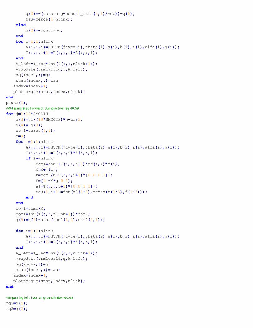
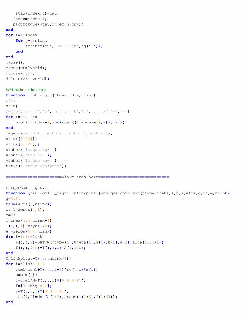
Matlab code for Torque calculation & simulation of 4-DOF biped robot

a(i)= fscanf(data,'%f',1);alfa(i)= fscanf(data,'%f',1);m(i)= fscanf(data,'%f',1);rg(1,i)= fscanf(data,'%f',1);rg(2,i)= fscanf(data,'%f',1);rg(3,i)= fscanf(data,'%f',1);
endq=zeros(1,nlink);[tau com1 Tright Tnlinkp1]=torqueComTright(jtype,theta,s,b,a,alfa,q,rg,m,nlink);rq2=atan(com1(1,1)/com1(2,1));sq=zeros(45*SMOOTH,nlink);stau=zeros(45*SMOOTH,nlink);index=1;%both feet on ground, lifting right leg index=1:10for j=1:5*SMOOTH
q(2)=rq2*j/(5*SMOOTH);[tau com1 Tright Tnlinkp1]=torqueComTright(jtype,theta,s,b,a,alfa,q,rg,m,nlink);r_right=Tright*[0 0 0 1]';if r_right(2,1)<vec
constang=atan(FootPushWidth/FootJointHight);q(5)=-(constang-acos(r_right(2,1)/vec))-q(2);tau=0;
elseq(5)=-constang;
endvrupdate(vrmlworld,q,T(:,:,1));sq(index,:)=q;stau(index,:)=tau;index=index+1;plottorque(stau,index,nlink);
end
%% rightleg raised, taking it forward index=11:20for j=1:5*SMOOTH
q(3)=-pi/(10*SMOOTH)*j;q(4)=-q(3);com1=zeros(4,1);M=0;[tau com1 Tright Tnlinkp1]=torqueComTright(jtype,theta,s,b,a,alfa,q,rg,m,nlink);q(2)=q(2)+atan(com1(1,1)/com1(2,1));vrupdate(vrmlworld,q,T(:,:,1));sq(index,:)=q;stau(index,:)=tau;index=index+1;plottorque(stau,index,nlink);
end
%% putting right leg back on ground index=21:29rq5=q(5);for j=4*SMOOTH:-1:0
q(2)=rq2/(5*SMOOTH)*j;q(5)=rq5/(5*SMOOTH)*j;[tau com1 Tright Tnlinkp1]=torqueComTright(jtype,theta,s,b,a,alfa,q,rg,m,nlink);
% r_right=Tright*[0 0 0 1]';

% if r_right(2,1)<vec% constang=atan(FootPushWidth/FootJointHight);% q(5)=-(constang-acos(r_right(2,1)/vec))-q(2);% tau=0;% else% q(5)=-constang;% end
vrupdate(vrmlworld,q,T(:,:,1));sq(index,:)=q;stau(index,:)=tau;index=index+1;plottorque(stau,index,nlink);
end
com1=zeros(4,1);M=0;
%% lifting left leg index=30:39for i=1:1:nlink
A(:,:,i)=DHTOM(jtype(i),theta(i),s(i),b(i),a(i),alfa(i),q(i));T(:,:,i+1)=T(:,:,i)*A(:,:,i);if i~=5
com1=com1+T(:,:,i+1)*rg(:,i)*m(i);M=M+m(i);
endendcom1=com1/M;com1=inv(T(:,:,nlink+1))*com1;rq5=atan(com1(1,1)/com1(2,1));T_req=eye(4,4);T_req(1:3,4)=T(1:3,4,nlink+1);A_left=eye(4,4);
for j=1:5*SMOOTHq(5)=-rq5/(5*SMOOTH)*j;
com1=zeros(4,1);M=0;for i=1:1:nlink
A(:,:,i)=DHTOM(jtype(i),theta(i),s(i),b(i),a(i),alfa(i),q(i));T(:,:,i+1)=T(:,:,i)*A(:,:,i);if i~=nlink
com1=com1+T(:,:,i+1)*rg(:,i)*m(i);M=M+m(i);r=com1/M-T(:,:,i+1)*[0 0 0 1]';f=[0 -M*g 0 1];a1=T(:,:,i+1)*[0 0 1 1]';tau(1,i+1)=dot(a1(1:3),cross(r(1:3),f(1:3)));
endendA_left=T_req*inv(T(:,:,nlink+1));r_left=A_left*A(:,:,1)*[0 0 0 1]';if r_left(2,1)<vec
constang=atan(FootPushWidth/FootJointHight);
q(2)=-(constang-acos(r_left(2,1)/vec))-q(5);tau=zeros(1,nlink);
elseq(2)=-constang;
endfor i=1:1:nlink
A(:,:,i)=DHTOM(jtype(i),theta(i),s(i),b(i),a(i),alfa(i),q(i));T(:,:,i+1)=T(:,:,i)*A(:,:,i);
endA_left=T_req*inv(T(:,:,nlink+1));vrupdate(vrmlworld,q,A_left);sq(index,:)=q;stau(index,:)=tau;index=index+1;plottorque(stau,index,nlink);
endpause(1);%% taking step forward, Swing active leg 40:59for j=1:10*SMOOTH
q(3)=pi/(10*SMOOTH)*j-pi/2;q(4)=-q(3);com1=zeros(4,1);M=0;for i=1:1:nlink
A(:,:,i)=DHTOM(jtype(i),theta(i),s(i),b(i),a(i),alfa(i),q(i));T(:,:,i+1)=T(:,:,i)*A(:,:,i);if i~=nlink
com1=com1+T(:,:,i+1)*rg(:,i)*m(i);M=M+m(i);r=com1/M-T(:,:,i+1)*[0 0 0 1]';f=[0 -M*g 0 1];a1=T(:,:,i+1)*[0 0 1 1]';tau(1,i+1)=dot(a1(1:3),cross(r(1:3),f(1:3)));
endendcom1=com1/M;com1=inv(T(:,:,nlink+1))*com1;q(5)=q(5)-atan(com1(1,1)/com1(2,1));
for i=1:1:nlinkA(:,:,i)=DHTOM(jtype(i),theta(i),s(i),b(i),a(i),alfa(i),q(i));T(:,:,i+1)=T(:,:,i)*A(:,:,i);
endA_left=T_req*inv(T(:,:,nlink+1));vrupdate(vrmlworld,q,A_left);sq(index,:)=q;stau(index,:)=tau;index=index+1;plottorque(stau,index,nlink);
end
%% putting left foot on ground index=60:68rq5=q(5);rq2=q(2);

for j=4*SMOOTH:-1:0q(5)=rq5/(5*SMOOTH)*j;q(2)=rq2/(5*SMOOTH)*j;[tau com1 Tright Tnlinkp1]=torqueComTright(jtype,theta,s,b,a,alfa,q,rg,m,nlink);A_left=T_req*inv(Tnlinkp1);A(:,:,1)=DHTOM(jtype(1),theta(1),s(1),b(1),a(1),alfa(1),q(1));r_left=A_left*A(:,:,1)*[0 0 0 1]';
% if r_left(2,1)<vec% constang=atan(FootPushWidth/FootJointHight);% q(2)=-(constang-acos(r_left(2,1)/vec))-q(5);% else% q(2)=-constang;% end
com1=zeros(4,1);M=0;for i=1:1:nlink
A(:,:,i)=DHTOM(jtype(i),theta(i),s(i),b(i),a(i),alfa(i),q(i));T(:,:,i+1)=T(:,:,i)*A(:,:,i);if i~=nlink
com1=com1+T(:,:,i+1)*rg(:,i)*m(i);M=M+m(i);r=com1/M-T(:,:,i+1)*[0 0 0 1]';f=[0 -M*g 0 1];a1=T(:,:,i+1)*[0 0 1 1]';tau(1,i+1)=dot(a1(1:3),cross(r(1:3),f(1:3)));
endendA_left=T_req*inv(T(:,:,nlink+1));vrupdate(vrmlworld,q,A_left);sq(index,:)=q;stau(index,:)=tau;index=index+1;plottorque(stau,index,nlink);
end
%% lifting right leg index=69:78com1=zeros(4,1);M=0;[tau com1 Tright Tnlinkp1]=torqueComTright(jtype,theta,s,b,a,alfa,q,rg,m,nlink);rq2=atan(com1(1,1)/com1(2,1));for j=1:5*SMOOTH
q(2)=rq2/(5*SMOOTH)*j;[tau com1 Tright Tnlinkp1]=torqueComTright(jtype,theta,s,b,a,alfa,q,rg,m,nlink);r_right=Tnlinkp1*[0 0 0 1]';if r_right(2,1)<vec
constang=atan(FootPushWidth/FootJointHight);q(5)=-(constang-acos(r_right(2,1)/vec))-q(2);tau=zeros(1,nlink);
elseq(5)=-constang;
endvrupdate(vrmlworld,q,A_left);sq(index,:)=q;
stau(index,:)=tau;index=index+1;plottorque(stau,index,nlink);
endfor i=1:index
for j=1:nlinkfprintf(out,'%d 0 0\n',sq(i,j));
endendpause();close(vrmlworld);fclose(out);delete(vrmlworld);
%% function to plot torquefunction plottorque(stau,index,nlink)clf;hold;c=['b','g','r','c','m','y','k','.','o','x','+','*'];for i=2:nlink
plot(1:index-1,abs(stau((1:index-1),i)),c(i));endlegend('motor1','motor2','motor3','motor4');xlim([1 90]);ylim([0 .25]);xlabel('Torque kg-m');xlabel('step no.');ylabel('Torque kg-m');title('Torque Analysis');
======================main.m ends here=============================
torqueComTright.mfunction [tau com1 T_right Tnlinkplus1]=torqueComTright(jtype,theta,s,b,a,alfa,q,rg,m,nlink)g=9.8;tau=zeros(1,nlink);com1=zeros(4,1);M=0;T=ones(4,4,nlink+1);T(:,:,1) =eye(4,4);A =zeros(4,4,nlink);for i=1:1:nlink
A(:,:,i)=DHTOM(jtype(i),theta(i),s(i),b(i),a(i),alfa(i),q(i));T(:,:,i+1)=T(:,:,i)*A(:,:,i);
endTnlinkplus1=T(:,:,nlink+1);for i=nlink:-1:2
com1=com1+T(:,:,i+1)*rg(:,i)*m(i);M=M+m(i);r=com1/M-T(:,:,i)*[0 0 0 1]';f=[0 -M*g 0 1];a=T(:,:,i)*[0 0 1 1]';tau(1,i)=dot(a(1:3),cross(r(1:3),f(1:3)));
end

T_right=T(:,:,nlink);
=========================== torqueComTright.m ends here==============
Vrupdate.mfunction vrupdate(world,q,T_FootL)%This fuction takes an open vrmlworld of file toddler.wrl% as first argument%As second argument it takes q which is row vector of %length 5 whose last 4 elements specify rotation about each joint%As third Argument it take T_FootL which is a 4x4 Homogenous Matrix% specifying roto-translation of the foot
world.FootL.translation=T_FootL(1:3,4)';[u,phi]=EXTRACT(T_FootL(1:3,1:3));world.FootL.rotation=[u(1), u(2), u(3), phi];world.HipL.rotation=[0 0 1 q(2)];world.MidLink.rotation=[0 1 0 q(3)];world.HipR.rotation=[0 1 0 q(4)];world.FootR.rotation=[0 0 1 q(5)];pause(.2);
%For demo purpose Run Following lines before this function%world=vrworld("<path>\toddler.wrl");%open(world);%view(world);%T_FootL=zeros(4,4);%q=[0 0 0 0 pi/3] % you can play with this===============vrupdate.m ends here=================================
Extract.mfunction [u,fi]=extract(r)
%EXTRACT (Spacelib): Extracts unit vector and rotation angle from a rotation matrix.%%% Extracts the unit vector u of the screw axis and the rotation angle fi % from a rotation matrix stored in the 3*3 left-upper submatrix of a matrix R. % EXTRACT performs the inverse operation of ROTAT.% Related functions: MTOSCREW, SCREWTOM, ROTAT% Usage:% [u,fi]=extract(R)%%% (c) G.Legnani, C. Moiola 1998; adapted from: G.Legnani and R.Faglia 1990% patched by g.legnani November 2001%___________________________________________________________________________
X=1; Y=2; Z=3; U=4;

u=[0 0 0]'; % u must be a columna=0.5*(r(Z,Y)-r(Y,Z));b=0.5*(r(X,Z)-r(Z,X));c=0.5*(r(Y,X)-r(X,Y));s=sqrt(a^2+b^2+c^2);co=0.5*(r(X,X)+r(Y,Y)+r(Z,Z)-1);
co=min(1,max(-1,co));fi=atan2(s,co);v=1-co;
if (norm(s)>0.1)u(X)=a/s;u(Y)=b/s;u(Z)=c/s;
elseif ( (fi~=0) & (co>0) )t=1/v;u(X)=sign(r(3,2)-r(2,3))*sqrt( abs((r(1,1)-co)*t));u(Y)=sign(r(1,3)-r(3,1))*sqrt( abs((r(2,2)-co)*t));u(Z)=sign(r(2,1)-r(1,2))*sqrt( abs((r(3,3)-co)*t));
elseif ( (fi~=0) & (co<0) )t=1/v;u(X)=sqrt( abs((r(1,1)-co)*t));u(Y)=sqrt( abs((r(2,2)-co)*t));u(Z)=sqrt( abs((r(3,3)-co)*t));
if ( (u(X)>=u(Y)) & (u(X)>=u(Z)) )x=1;
elseif ( (u(Y)>=u(X)) & (u(Y)>=u(Z)) )x=2;
elsex=3;
endy=rem(x,3)+1;z=rem(x+1,3)+1;
if (r(z,y)-r(y,z))>=0s=1; % segno
elses=-1;
endu(x)=u(x)*s;u(y)=u(y)*sign(r(y,x)+r(x,y))*s;u(z)=u(z)*sign(r(z,x)+r(x,z))*s;
elseu=[0 0 0 ]; % rotation axis is undefined (fi==0)
end====================Extrtact.m ends here=============================

#include <p18cxxx.h>#include <adc.h>#include <delays.h> /** V A R I A B L E S ********************************************************/#pragma udata
/** P R I V A T E P R O T O T Y P E S ***************************************/
/** V E C T O R R E M A P P I N G *******************************************/
extern void _startup (void);#pragma code _RESET_INTERRUPT_VECTOR = 0x000800void _reset (void){
_asm goto _startup _endasm}#pragma code
#pragma code _HIGH_INTERRUPT_VECTOR = 0x000808void _high_ISR (void){
;}
#pragma code _LOW_INTERRUPT_VECTOR = 0x000818void _low_ISR (void){
;}#pragma code
#define mInitAll() TRISA &= 0x01; LATA &= 0x00; TRISE=0x00 ;LATE &=0x00
#define mMotor_1 LATEbits.LATE1#define mMotor_2 LATAbits.LATA4#define mMotor_3 LATAbits.LATA3#define mMotor_4 LATAbits.LATA2
#define mMotor_1_On() mMotor_1 = 1;#define mMotor_2_On() mMotor_2 = 1; #define mMotor_3_On() mMotor_3 = 1; #define mMotor_4_On() mMotor_4 = 1;
#define mMotor_1_Off() mMotor_1 = 0;#define mMotor_2_Off() mMotor_2 = 0;#define mMotor_3_Off() mMotor_3 = 0;#define mMotor_4_Off() mMotor_4 = 0;
#define mMotor_1_Toggle() mMotor_1 = !mMotor_1;#define mMotor_2_Toggle() mMotor_2 = !mMotor_2;#define mMotor_3_Toggle() mMotor_3 = !mMotor_3;#define mMotor_4_Toggle() mMotor_4 = !mMotor_4;
Final C-Source Code for Feedback controlled biped robot.

/** COUNT CALCULATIONS***********************************************/#define MAX_COUNT 1000 //for angle:200 degree#define MIN_COUNT 230 //for angle:0 degree#define MID_COUNT 605 //for angle:100 degree#define ANGLE_TO_COUNT(X) (float)(MID_COUNT+(float)(X)*(MAX_COUNT-MIN_COUNT)/180)#define NO_OF_STEPS 10// function declarationvoid walk(int step);void move_left_leftup(void);void move_right_leftup(void);void move_right_rightup(void);void move_left_rightup(void);void setangle(int No_of_pulses,int s1,int s2,int s3,int s4);
//angle of corresponding motor at any timeint angle1,angle2,angle3,angle4;
void main(){
int left,right;mInitAll();
ADCON2= 0b00000010;ADCON1 = 0b00001110;ADCON0 = 0b00000000;ADCON0 |= 0b00000001;walk(-1);
}
void walk(int step){int e=0,left=1,right=1;while(1){
switch(step){
case -1://from startangle1=0;angle2=-60;angle3=-60;angle4=0;
case 0 :setangle(2,angle1,angle2,angle3,angle4);
// right leg forwardstep=-1;
if(ADRESH>=0x1F)left=0;
elseleft=1;
angle1=-60;angle4=-50;setangle(2,angle1,angle2,angle3,angle4);angle2=0;angle3=0;setangle(2,angle1,angle2,angle3,angle4);
if(ADRESH>=0x1F)

{if(left)move_left_leftup();
else if(right)move_right_leftup();else{e=1;break;}}
angle2=+77;angle3=+77;setangle(1,angle1,angle2,angle3,angle4);angle4=0;setangle(1,angle1,angle2,angle3,angle4);angle1=0;
case 1:setangle(2,angle1,angle2,angle3,angle4);step=-1;
//left leg forward
if(ADRESH>=0x1F)right=0;
elseright=1;
angle4=58;angle1=50;setangle(2,angle1,angle2,angle3,angle4);angle2=0;angle3=0;setangle(2,angle1,angle2,angle3,angle4);if(ADRESH>=0x1F)
{if(right)move_right_rightup();
else if(left)move_left_rightup();else{e=1;break;}}
angle2=-67;angle3=-67;setangle(1,angle1,angle2,angle3,angle4);angle1=0;setangle(1,angle1,angle2,angle3,angle4);angle4=0;setangle(1,angle1,angle2,angle3,angle4);
}if(e) break;}}
void move_left_leftup(){angle2=-50;setangle(1,angle1,angle2,angle3,angle4);angle4=0;setangle(1,angle1,angle2,angle3,angle4);angle1=0;setangle(1,angle1,angle2,angle3,angle4);

angle4=58;angle1=50;setangle(2,angle1,angle2,angle3,angle4);angle2=-60;angle3=-60;setangle(2,angle1,angle2,angle3,angle4);angle1=0;setangle(2,angle1,angle2,angle3,angle4);angle4=0;setangle(2,angle1,angle2,angle3,angle4);walk(0);}void move_right_leftup(){angle2=45;setangle(1,angle1,angle2,angle3,angle4);angle4=0;setangle(1,angle1,angle2,angle3,angle4);angle1=0;setangle(1,angle1,angle2,angle3,angle4);angle4=58;angle1=50;setangle(2,angle1,angle2,angle3,angle4);angle2=+77;angle3=+77;setangle(1,angle1,angle2,angle3,angle4);angle1=0;setangle(2,angle1,angle2,angle3,angle4);angle4=0;setangle(2,angle1,angle2,angle3,angle4);walk(1);}
void move_right_rightup(){angle3=45;setangle(1,angle1,angle2,angle3,angle4);angle1=0;setangle(1,angle1,angle2,angle3,angle4);angle4=0;setangle(1,angle1,angle2,angle3,angle4);angle1=-60;angle4=-50;setangle(1,angle1,angle2,angle3,angle4);angle2=+77;angle3=+77;setangle(1,angle1,angle2,angle3,angle4);angle4=0;setangle(2,angle1,angle2,angle3,angle4);angle1=0;setangle(2,angle1,angle2,angle3,angle4);walk(1);}
void move_left_rightup(){angle3=-50;setangle(1,angle1,angle2,angle3,angle4);angle1=0;setangle(1,angle1,angle2,angle3,angle4);

angle4=0;setangle(1,angle1,angle2,angle3,angle4);angle1=-60;angle4=-50;setangle(2,angle1,angle2,angle3,angle4);angle2=-60;angle3=-60;setangle(2,angle1,angle2,angle3,angle4);angle4=0;setangle(2,angle1,angle2,angle3,angle4);angle1=0;setangle(2,angle1,angle2,angle3,angle4);walk(0);}
void setangle(int No_of_pulses,int s1,int s2,int s3,int s4){int k,l;int c1,c2,c3,c4;c1=ANGLE_TO_COUNT(s1)-35;c2=ANGLE_TO_COUNT(s2);c3=ANGLE_TO_COUNT(s3);c4=ANGLE_TO_COUNT(s4)+50;
for (k=0;k<No_of_pulses*20;k++){
//motor 1 ON time mMotor_1_On();for(l=0;l<c1;l++) {}mMotor_1_Off();//motor 3 ON time mMotor_3_On();for(l=0;l<c3;l++) {}mMotor_3_Off();//motor 2 ON time mMotor_2_On();for(l=0;l<c2;l++) {}mMotor_2_Off();//motor 4 ON time mMotor_4_On();for(l=0;l<c4;l++) {}mMotor_4_Off();//sensor sensingDelay100TCYx (1);/* start the ADC conversion */ADCON0 |= 0x02;while (ADCON0 & 0x02){}//cumulative OFF timefor(l=0;l<15000-(c1+c2+c3+c4);l++){}
}}