december 18, 2012 city manager city of richmond 450 civic
TRANSCRIPT

1
December 18, 2012 Mr. William Lindsay City Manager City of Richmond 450 Civic Center Plaza Richmond, CA 94804
Re: Material Selection For Repair Of Damaged Process Piping In High-Temperature Sulfidation
Service In The No. 4 Crude Unit – December 12, 2012, Application for City of Richmond Permits
Dear Mr. Lindsay:
At the request of the City of Richmond, California, I have prepared this letter to provide an opinion as to whether the use of 9Cr material as a replacement for fire damaged piping in high-temperature sulfidation service in the No. 4 Crude Unit will meet the requirements of the California Fire Code (CFC).
Background Information
Chevron U.S.A. Inc. has submitted applications to the City of Richmond for permits pursuant to the California Fire Code to replace fire damaged piping in high temperature sulfidation service in the Crude Unit with 9 Chrome (“9Cr”) alloy pipe. Chevron has prepared a technical report (the report) responding to the City of Richmond’s request for additional information concerning Chevron’s selection of materials for this repair. The decision on which materials to use is to be made by Chevron. However, prior to issuing the fire construction permits, the City of Richmond would like to conduct an independent review of the material selection for conformance with the CFC.
Scope of Assignment
It is my understanding that the assignment involves reviewing the referenced Chevron report, plus supporting documents (see references) and confirming that their material selection meets the CFC. The review should also assess whether the report is sufficiently complete to evaluate concurrence with the CFC. Although not directly related to compliance with the CFC, in order to provide a more complete review of the Chevron technical report, I have also reviewed Chevron's discussion on the American Petroleum Institute’s (API’s) Recommended Practice (RP) 939-C Guidelines for Avoiding Sulfidation Corrosion Failures in Oil Refineries.
City of Richmond Permitting Process & Requirements
The following summary describes my understanding of the City of Richmond permitting process and requirements for replacement of fire-damaged piping in high-temperature sulfidation service in the No. 4 Crude Unit, based on the information included in Appendix A:

2
Chevron selects materials for the repair work and submits building and fire permit applications to the City of Richmond. The City of Richmond first conducts a plan check to verify that no new or different equipment will be installed that would allow an increase in emissions or unit throughput. The City of Richmond also confirms that no discretionary permit approval is required (i.e., for changes to increase the quantities of throughput through the crude unit or change the category of chemicals to a more hazardous category).
Following these initial reviews, the building permit is reviewed for compliance with the California Building Code (CBC)(24 Cal. Code Regs Part 2), including codes, standards, and publications adopted as standard reference documents and enforced as part of the CBC. (CBC §§ 1.1.3; 1.1.5; 1.8.6.1). If the Building Official finds that the work described in an application and the plans, specifications, and other data filed with the application conforms to the requirements of RMC Chapter 6.02, including the CBC and associated standard reference documents, and that required building permit fees have been paid, the Building official must issue the requested building permit to the applicant. (RMC § 6.02.170(a)).
The fire permit applications are then reviewed for conformance with the CFC (and reference standards cited in the CFC), including Chapter 27 (Hazardous Materials) and Chapter 34 (Flammable and Combustible Liquids). For example, CFC Sections 3403.6.1 through 3403.6.11 apply to piping systems and their component parts for flammable and combustible liquids. These provisions require that piping systems and component parts for flammable and combustible liquids shall be designed and fabricated in accordance with the applicable standards listed in CFC Chapter 47. Fire construction permit applications submitted in connection with the Repair Project are reviewed to determine whether piping and component parts for flammable and combustible liquids meet the requirements set forth in CFC Sections 3403.6.1 through 3403.6.11, as well as any reference standards cited in those sections. Based on communication with the Richmond Fire Marshal, the referenced standards include the American Society of Mechanical Engineers (ASME) Code for Process Piping (ASMEB.31.3) and the fire safety standards of the National Fire Protection Association (NFPA) Flammable and Combustible Liquids Code (NFPA30). If the Fire Code Official is satisfied that the proposed work or operation conforms to the requirements of the CFC (including codes and standards listed in CFC Chapter 47 that are considered part of the CFC requirements), and laws and ordinances applicable thereto, the Fire Code Official is required to issue a permit as soon as practicable. (CFC §§ 1.1.5, 102.7; 105.2.4).
Discussion
The Technical Analysis section of the Chevron report states that: “Pursuant to ASME B31.3 and NFPA30, carbon steel, 5 Chrome alloy (“5Cr”), 9Cr, and 300 series Stainless Steel (“300SS”) are suitable for service in the Crude Unit.” Appendix I of the report describes Chevron’s understanding of the permitting process, the pertinent sections of the 2010 California Fire Code, Title 24, Part 9 and their technical basis for justification that 9Cr material meets the CFC requirements, specifically, Chapter 27 – Hazardous Materials, and Chapter 34 – Flammable and Combustible Materials. With respect to piping handling hazardous chemicals, those two chapters refer to the requirements of ASME B31.3, Process Piping and NFPA 30, Flammable and Combustible Liquids Code. Chevron discusses their opinion that the use of 9Cr meets the CFC requirements in Appendix I; Technical Standards of the CFC section.
Chevron also states in the Technical Analysis section of the report that API 939‐C identifies carbon steel with adequate silicon, 5Cr, 9Cr, and 300 SS as examples of materials suitable for high temperature sulfidation (HTS) service, depending on various factors. This is demonstrated by the Modified McConomy Curves, presented in API 939‐C, which show the sulfidation corrosion rates of carbon steel

3
with silicon, 5Cr, 9Cr, and 300 SS. According to Chevron, each of these materials may be suitable for HTS service in the Crude Unit, in particular when one takes into account the Crude Unit’s operational history.
Opinions
Based on communication with the City of Richmond Fire Marshal and my review of: (1) the City of Richmond memorandum outlining the permitting process (Appendix A), (2) the Chevron report, including Appendix I, (3) the 2010 California Fire Code, Title 24, Part 9, Chapters 27, 34 and 47, (4) ASME B31.3, (5) NFPA 30, 2012 Ed and (6) API RP 939-C, I offer the following opinions:
The use of 9Cr material meets the requirements of CFC, based on compliance with B31.3 and NFPA 30. My opinion that 9Cr material meets the requirements of B31.3 is supported by the extracts from B31.3 (Appendix B). In summary, B31.3 is intended to be a code detailing requirements for the design, fabrication, testing and inspection of piping, piping components and piping supports. B31.3 scope states that the piping designer is responsible for the selection of piping materials to resist corrosion and erosion (K 302.1). It further states that “Any material used in pressure containing piping components shall conform to a listed specification except as provided in paragraph 323.1.2.” 9Cr material is a listed material in B31.3 with allowable stresses to be used in pressure containment design, if ordered to the requirements of one of the listed ASTM specifications for that material, such as ASTM A335 (Appendix C).
Similarly, in NFPA 30 the primary section relating to compliance with this code is Chapter 27 – Piping Systems. Paragraph 27.4.1 Materials Specifications, states that “Pipe, valves, faucets, couplings, flexible connectors, fittings, and other pressure-containing parts shall meet the material specifications and pressure and temperature limitations of ASME B31, Code for Pressure Piping, except as provided for in 27.4.2, 27.4.3, and 27.4.4.” (Appendix D). The appropriate B31 Code for Pressure Piping for the Chevron No. 4 Crude Unit rebuild is B31.3, Process Piping and the support for 9Cr material meeting the requirements of B31.3 has been provided.
There are two distinct and separate sets of curves that the industry uses to predict high-temperature sulfidation corrosion. These curves, plus other information and data useful for material selection in high-temperature sulfur containing environments, are included in API RP 939-C. The RP is intended to provide practical guidance to inspectors, maintenance, reliability, project, operations and corrosion personnel on how to address sulfidation corrosion in petroleum refining operations.
The modified McConomy curves are intended to be used in H2 free streams. These curves show that at a given temperature and total sulfur level, steels with increasing chromium content (from carbon steel, to 5Cr to 9Cr to stainless steel) will experience lower corrosion rates. Where no prior experience or information is available, the modified McConomy curves would indicate the following materials selections for resistance to sulfidation corrosion (not considering the effect of naphthenic acid corrosion or mercaptan corrosion) in H2-free, 2 wt.% S environments is as follows:
Carbon steel for temperatures up to 525 °F (275 °C). Use fully killed steels to assure
silicon content > 0.10 wt %.

4
5Cr-0.5Mo for temperatures between 525 °F and 620 °F (275 °C and 325 °C).
9Cr-1Mo above 620 °F (325 °C).
These selections could vary depending on sulfur species, hydrocarbon phase, flow regime and the other operating variables; therefore, materials and corrosion specialists should be consulted for additional unit-specific interpretation and application of the RP. In summary, API RP 939-C is a recommended practice that provides guidelines on the mechanism of high-temperature sulfidation, parameters that affect corrosion rates and operating regimes where various materials are known to resist high-temperature sulfidation, based on experience and empirical data. 9Cr is one such alloy included in RP 939-C. It is the responsibility of an experienced materials and corrosion specialist to select the most appropriate alloy for the specific application at hand.
In Chevron’s selection of 9Cr material as replacement piping for the No. 4 Crude Unit rebuild project, it is my opinion that, based on my review of their technical report, Chevron followed a logical, technically sound and defendable basis for their selection. Chevron stated that they relied on experienced materials engineers to conduct the material selection review and recognized that any selection of material must include a comprehensive monitoring and inspection program to ensure that the selection would meet performance expectations. They also appeared to recognize the complexity of the material selection process and the many input parameters that needed to be reviewed in order to make an appropriate selection. Their use of API RP 939-C as an industry recognized resource document in their selection process was appropriate.
I am not in a position as of this writing to fully evaluate Chevron’s selection of 9Cr for replacement piping material, as I have not reviewed the process, operational and maintenance data required to do so. However, assuming that both 9Cr and 300SS are resistant to the type of high-temperature sulfidation environment encountered in the Crude Unit at the Chevron Richmond Refinery, Chevron’s rationale for selecting 9Cr material versus 300SS is appropriate. The 300SS alloys are widely known for their susceptibility to chloride stress corrosion cracking (CSCC) in aqueous streams containing chlorides at temperatures greater than approximately 140 degrees Fahrenheit. The unstabilized grades of the SS alloys are also susceptible to polythionic acid stress corrosion cracking (PASCC) in sulfur containing environments when exposed to oxygen. Internal CSCC and PASCC are damage mechanisms that are difficult to detect from the exterior of pressure containment components. Because high-temperature sulfidation causes general corrosion, detection of this damage mechanism is much easier using conventional non-destructive inspection techniques.
Conclusions
1. Based on my review of the documents cited in the References section of this letter, I agree with the interpretation in the Chevron report that 9Cr material meets the requirements of CFC and its referenced standards and codes.
2. I found that the Chevron report was sufficiently complete to evaluate concurrence with the CFC.

5
3. API 939-C is an appropriate resource document for selecting materials for the rebuild of the Chevron Crude Unit.
4. Based on the information contained in Chevron’s technical report, it is my opinion that Chevron’s logic and procedures used in their materials selection process is consistent with industry practice.
5. These opinions are limited to the review and conclusions set forth above, and do not constitute a professional opinion that Chevron should install 9Cr materials in its repair project.
I trust that this letter complies with your request for information on the selection of 9Cr in support of the permitting process.
Sincerely, David E. Hendrix, P.E. President The Hendrix Group, Inc.
6
References
1. Memorandum from Lina Velasco (City of Richmond Senior Planner) to Richard Mitchell (City of Richmond Director of Planning and Building Services). Overview of City Building and Fire Permit Review Process, November 7, 2012.
2. Chevron Report - Material Selection For Repair Of Damaged Process Piping In High-Temperature Sulfidation Service in the No. 4 Crude Units, December 12, 2012.
3. The 2010 California Fire Code, Title 24, Part 9, Chapters 27, 34 and 47.
4. ASME B31.3, Process Piping, 2008.
5. NFPA 30, Flammable and Combustible Liquids Code, 2012.
6. API RP 939-C, Guidelines for Avoiding Sulfidation Corrosion Failures in Oil Refineries.

Appendix A
City of Richmond Fire Permit Review Process Letter
450 Civic Center Plaza, Richmond, CA 94804-1630 Telephone: (510) 620-6706 Fax: (510) 620-6858 www.ci.richmond.ca.us
PLANNING DEPARTMENT
DATE: November 7, 2012 TO: Richard Mitchell, Director of Planning and Building Services FROM: Lina Velasco, Senior Planner CC: Terry Harris, Fire Marshal SUBJECT: Overview of City Building and Fire Permit Review Process for Chevron No. 4 Crude Unit and No. 3 Cat Cooling Tower Repair
I. INTRODUCTION
Pursuant to your request and to our discussions, this memorandum briefly describes: 1) the City of Richmond’s (City) process for issuing building and fire permits relating to the repair of the Chevron Crude No. 4 Unit and No. 3 Cat Cooling Tower that were damaged by the August 6, 2012 fire (Repair Project); and 2) how the City determined that issuance of these permits are ministerial actions by the City.
The Repair Project includes the removal and replacement or repair of structural steel, electrical systems and connections, instrumentation and the cooling tower structure, as well as process equipment such as pressure vessels, tanks, pumps, and piping. As documented by Chevron in its October 6, 2012 notification to the City (Repair Project Description), all repair and replacement equipment/materials are to be repaired or replaced with “in-kind” or equivalent equipment/materials that meet or exceed applicable industry standards and/or codes. No new or different equipment will be installed that would allow an increase in emissions or unit throughput or changes to the operation of the crude unit, cooling tower, and associated equipment. The plan check process has been and will be used to verify that no new or different equipment will be installed that would allow an increase in emissions or unit throughput or changes to the operation of the crude unit, cooling tower, and associated equipment.
As described further below, the proposed Repair Project has not required any discretionary actions by the City and involves only the issuance of building permits and fire permits by the City.
II. DISCUSSION
A. Review for Applicability of City Discretionary Permits
The City reviewed the Repair Project components to confirm that no discretionary City approval by the City is required. For example, if the Repair Project were to propose a modification that would increase the quantities of throughput through the crude unit or change the category of chemicals to a more hazardous category, a conditional use permit would be
Page 2 of 4
required per Section 15.04.820.020 of the Richmond Municipal Code (RMC). The Repair Project Description, however, does not propose these modifications. Per Section 15.4.930.020(C)(6) of the RMC, “replacement or reconstruction of existing equipment and appurtenant facilities where new equipment and facilities are similar in size, design, and appearance to the equipment or facility replaced” are exempt from Design Review. Because Chevron is only seeking such replacement/reconstruction of existing equipment, their proposed work is exempt from Design Review. Of course, the City reviews each building and fire permit as it is submitted to confirm that none of the Repair Project components deviate from the overall Repair Project Description so as to trigger the need for a discretionary approval.
B. Building Permits
Under the City’s Building Regulations Administrative Code, a building permit is required to construct, enlarge, alter, repair, move, improve, remove, convert, or demolish a building, structure, or service equipment. (RMC § 6.02.150(a)). In order to obtain a building permit, the permit application must identify the work to be covered by the permit. (RMC § 6.02.160(A)). The application must include plans and specifications that indicate the location, nature, and extent of the work proposed and show in detail that the work will conform to the provisions of the technical codes and all relevant laws, ordinances, rules and regulations. (RMC §§ 6.02.160(B)-(C)).
The application is reviewed by the Building Official, and may be reviewed by other departments to verify compliance with any applicable laws under their jurisdiction. (RMC § 6.02.170(a)). Review of a building permit application includes review for compliance with the California Building Code (CBC)(24 Cal. Code Regs Part 2), including codes, standards, and publications adopted as standard reference documents and enforced as part of the CBC. (CBC §§ 1.1.3; 1.1.5; 1.8.6.1).
If the Building Official finds that the work described in an application and the plans, specifications, and other data filed with the application conforms to the requirements of RMC Chapter 6.02, including the CBC and associated standard reference documents, and that required building permit fees have been paid, the Building official must issue the requested building permit to the applicant. (RMC § 6.02.170(a)). This action is ministerial, as further described in Section D below.
C. Fire Permits
The City Fire Department (which also contracts with the Contra Costa County Fire District for fire permit plan review and inspection services), administers the California Fire Code (CFC) permit requirements (24 Cal. Code Regs. Part 9). A fire permit is required under specified conditions to: (1) maintain, store or handle hazardous materials; (2) conduct processes which produce conditions hazardous to life or property; (3) install equipment utilized in connection with such activities; (4) install or modify any fire protection system or equipment; or (5) engage in other construction, equipment installation or modification activities where a fire permit is required. (CFC § 105.3, 105.6, and 105.7).

Page 3 of 4
While the Building Code requires permits for construction activities, the Fire Code requires both construction permits as well as annual operating permits for designated activities.
Construction permits allow an applicant to install or modify systems and equipment that require a permit under CFC Section 105.7.
Operational permits allow an applicant to conduct an operation or business that requires a permit under CFC Section 105.6. (CFC § 105.1.2).
Section 105 of the CFC outlines the permit application process. A permit application must include construction documents and supporting data to indicate the location, nature, and extent of the work proposed, and must show in detail that the work will conform to the provisions of the CFC and relevant laws, ordinances, rules and regulations. (CFC §§ 105.4.1 - 105.4.2).
Fire permit applications for the Repair Project are reviewed for conformance with the CFC (and reference standards cited in the CFC), including Chapter 27 (Hazardous Materials) and Chapter 34 (Flammable and Combustible Liquids). For example, CFC Sections 3403.6.1 through 3403.6.11 apply to piping systems and their component parts for flammable and combustible liquids. These provisions require that piping systems and component parts for flammable and combustible liquids shall be designed and fabricated in accordance with the applicable standards listed in CFC Chapter 47. Fire construction permit applications submitted in connection with the Repair Project are reviewed to determine whether piping and component parts for flammable and combustible liquids meet the requirements set forth in CFC Sections 3403.6.1 through 3403.6.11, as well as any reference standards cited in those sections.
If the Fire Code Official is satisfied that the proposed work or operation conforms to the requirements of the CFC (including codes and standards listed in CFC Chapter 47 that are considered part of the CFC requirements), and laws and ordinances applicable thereto, the Fire Code Official is required to issue a permit as soon as practicable. (CFC §§ 102.7; 105.2.4). This action is ministerial, as further described below.
D. CEQA Considerations
The California Environmental Quality Act (CEQA) applies only to discretionary City approvals, and does not apply to ministerial approvals. (Cal. Pub. Res. Code § 21080(a), (b)). A "ministerial" decision is defined as:
[A] governmental decision involving little or no personal judgment by the public official as to the wisdom or manner of carrying out the project. The public official merely applies the law to the facts as presented but uses no special discretion or judgment in reaching a decision. A ministerial decision involves only the use of fixed standards or objective measurements, and the public official cannot use personal, subjective judgment in deciding whether or how the project should be carried out....
(CEQA Guidelines § 15369).
Page 4 of 4
The City's Guidelines and Procedures for the Implementation of the California Environmental Quality Act (Adopted September 23, 2003, Resolution No. 125-03) identify issuance of a building permit as an example of a ministerial decision.
Approval of a building permit or fire construction or operation permit in accordance with the City's procedures as outlined in this report are ministerial and statutorily exempt from CEQA where (1) the application is reviewed for conformance with specific standards or objective measurements, and (2) the permit must be issued if applicable objective standards and objectives measurements are met. Here, for the Repair Project, each component of the repair activity is reviewed to identify applicable standards and, if the activity complies with applicable standards, the permit is issued as a ministerial decision. If the permit application does not demonstrate compliance with applicable standards, the permit application is denied until and unless the application is modified to demonstrate compliance.
III. CONCLUSION
Consistent with the above analysis, the City has determined that the Repair Project permits issued to date by the City are exempt under CEQA as ministerial actions. The City has issued building permits for the Repair Project consistent with these laws. In addition, the City continues to coordinate with the other agencies who are investigating the August 6, 2012 fire. Notably, as you know, CSB and CalOSHA provided the City with written notification that they have no objection to the City’s issuance of permits related to the repair. In addition, the Bay Area Air Quality Management District (BAAQMD) has, like the City, determined that no discretionary BAAQMD approvals are required for the Repair Project based on information provided by Chevron to date. BAAQMD is reviewing components of the Repair Project to ensure the repair work does not result in an increase of throughput through the crude unit and that Chevron’s proposal to incorporate best available control technology (BACT) is demonstrated in the plans for the Repair Project. City staff is continuing to coordinate with those agencies reviewing the Repair Project and investigating the root cause of the August 6, 2012 fire.

Appendix B
B31.3 Excerpts
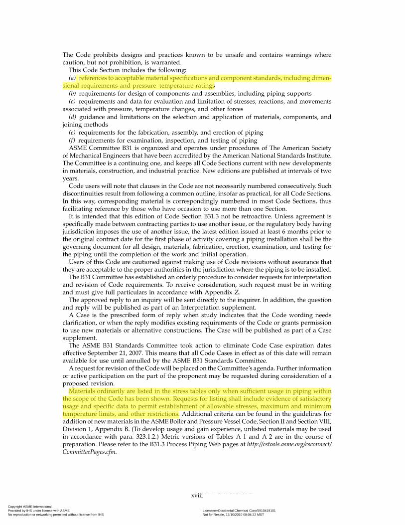
The Code prohibits designs and practices known to be unsafe and contains warnings wherecaution, but not prohibition, is warranted.
This Code Section includes the following:(a) references to acceptable material specifications and component standards, including dimen-
sional requirements and pressure–temperature ratings(b) requirements for design of components and assemblies, including piping supports(c) requirements and data for evaluation and limitation of stresses, reactions, and movements
associated with pressure, temperature changes, and other forces(d) guidance and limitations on the selection and application of materials, components, and
joining methods(e) requirements for the fabrication, assembly, and erection of piping(f) requirements for examination, inspection, and testing of pipingASME Committee B31 is organized and operates under procedures of The American Society
of Mechanical Engineers that have been accredited by the American National Standards Institute.The Committee is a continuing one, and keeps all Code Sections current with new developmentsin materials, construction, and industrial practice. New editions are published at intervals of twoyears.
Code users will note that clauses in the Code are not necessarily numbered consecutively. Suchdiscontinuities result from following a common outline, insofar as practical, for all Code Sections.In this way, corresponding material is correspondingly numbered in most Code Sections, thusfacilitating reference by those who have occasion to use more than one Section.
It is intended that this edition of Code Section B31.3 not be retroactive. Unless agreement isspecifically made between contracting parties to use another issue, or the regulatory body havingjurisdiction imposes the use of another issue, the latest edition issued at least 6 months prior tothe original contract date for the first phase of activity covering a piping installation shall be thegoverning document for all design, materials, fabrication, erection, examination, and testing forthe piping until the completion of the work and initial operation.
Users of this Code are cautioned against making use of Code revisions without assurance thatthey are acceptable to the proper authorities in the jurisdiction where the piping is to be installed.
The B31 Committee has established an orderly procedure to consider requests for interpretationand revision of Code requirements. To receive consideration, such request must be in writingand must give full particulars in accordance with Appendix Z.
The approved reply to an inquiry will be sent directly to the inquirer. In addition, the questionand reply will be published as part of an Interpretation supplement.
A Case is the prescribed form of reply when study indicates that the Code wording needsclarification, or when the reply modifies existing requirements of the Code or grants permissionto use new materials or alternative constructions. The Case will be published as part of a Casesupplement.
The ASME B31 Standards Committee took action to eliminate Code Case expiration dateseffective September 21, 2007. This means that all Code Cases in effect as of this date will remainavailable for use until annulled by the ASME B31 Standards Committee.
A request for revision of the Code will be placed on the Committee’s agenda. Further informationor active participation on the part of the proponent may be requested during consideration of aproposed revision.
Materials ordinarily are listed in the stress tables only when sufficient usage in piping withinthe scope of the Code has been shown. Requests for listing shall include evidence of satisfactoryusage and specific data to permit establishment of allowable stresses, maximum and minimumtemperature limits, and other restrictions. Additional criteria can be found in the guidelines foraddition of new materials in the ASME Boiler and Pressure Vessel Code, Section II and Section VIII,Division 1, Appendix B. (To develop usage and gain experience, unlisted materials may be usedin accordance with para. 323.1.2.) Metric versions of Tables A-1 and A-2 are in the course ofpreparation. Please refer to the B31.3 Process Piping Web pages at http://cstools.asme.org/csconnect/CommitteePages.cfm.
xviii
Copyright ASME International Provided by IHS under license with ASME Licensee=Occidental Chemical Corp/5910419101
Not for Resale, 12/10/2010 08:04:22 MSTNo reproduction or networking permitted without license from IHS
--`,,````,``,,,`````,,,`,,`,,`,-`-`,,`,,`,`,,`---

ASME B31.3-2008
Chapter IIIMaterials
323 GENERAL REQUIREMENTSChapter III states limitations and required qualifica-
tions for materials based on their inherent properties.Their use in piping is also subject to requirements andlimitations in other parts of this Code [see para. 300(d)].See also para. 321.1.4 for support materials,and Appendix F, para. F323, for precautionaryconsiderations.
323.1 Materials and Specifications
323.1.1 Listed Materials. Any material used in pres-sure containing piping components shall conform to alisted specification except as provided in para. 323.1.2.
323.1.2 Unlisted Materials. Unlisted materials maybe used provided they conform to a published specifica-tion covering chemistry, physical and mechanical prop-erties, method and process of manufacture, heattreatment, and quality control, and otherwise meet therequirements of this Code. Allowable stresses shall bedetermined in accordance with the applicable allowablestress basis of this Code or a more conservative basis.
323.1.3 Unknown Materials. Materials of unknownspecification shall not be used for pressure-containingpiping components.
323.1.4 Reclaimed Materials. Reclaimed pipe andother piping components may be used, provided theyare properly identified as conforming to a listed or pub-lished specification (para. 323.1.1 or 323.1.2) and other-wise meet the requirements of this Code. Sufficientcleaning and inspection shall be made to determine min-imum wall thickness and freedom from imperfectionswhich would be unacceptable in the intended service.
323.2 Temperature LimitationsThe designer shall verify that materials which meet
other requirements of the Code are suitable for servicethroughout the operating temperature range. Attentionis directed to Note (7) in Appendix A, which explainsthe means used to set both cautionary and restrictivetemperature limits in Tables A-1 and A-2.
323.2.1 Upper Temperature Limits, Listed Materi-als. A listed material may be used at a temperatureabove the maximum for which a stress value or ratingis shown, only if
(a) there is no prohibition in Appendix A or elsewherein the Code
(b) the designer verifies the serviceability of the mate-rial in accordance with para. 323.2.4
45
323.2.2 Lower Temperature Limits, Listed Materials(a) A listed material may be used at any temperature
not lower than the minimum shown in Table A-1, pro-vided that the base metal, weld deposits, and heat-affected zone (HAZ) are qualified as required by theapplicable entry in Column A of Table 323.2.2.
(b) For carbon steels with a letter designation in theMin. Temp. column of Table A-1, the minimum tempera-ture is defined by the applicable curve and Notes inFig. 323.2.2A. If a design minimum metal temperature-thickness combination is on or above the curve, impacttesting is not required.
(c) A listed material may be used at a temperaturelower than the minimum shown in Table A-1 orFig. 323.2.2A (including Notes), unless prohibited inTable 323.2.2, Table A-1, or elsewhere in the Code, andprovided that the base metal, weld deposits, and HAZare qualified as required by the applicable entry inColumn B of Table 323.2.2.
(d) Where the stress ratio defined in Fig. 323.2.2B isless than one, Fig. 323.2.2B provides a further basis forthe use of carbon steels covered by paras. 323.2.2(a) and(b), without impact testing.
(1) For design minimum temperatures of −48°C(−55°F) and above, the minimum design metal tempera-ture without impact testing determined in para.323.2.2(b), for the given material and thickness, may bereduced by the amount of the temperature reductionprovided in Fig. 323.2.2B for the applicable stress ratio.If the resulting temperature is lower than the minimumdesign metal temperature, impact testing of the materialis not required. Where this is applied, the piping systemshall also comply with the following requirements:
(a) The piping shall be subjected to a hydrostatictest at no less than 11⁄2 times the design pressure.
(b) Except for piping with a nominal wall thick-ness of 13 mm (1⁄2 in.) or less, the piping system shallbe safeguarded (see Appendix G) from external loadssuch as maintenance loads, impact loads, and thermalshock.
(2) For design minimum temperatures lower than−48°C (−55°F), impact testing is required for all materi-als, except as provided by Note (3) of Table 323.2.2.
(e) The allowable stress or component rating at anytemperature below the minimum shown in Table A-1or Fig. 323.2.2A shall not exceed the stress value orrating at the minimum temperature in Table A-1 or thecomponent standard.
Copyright ASME International Provided by IHS under license with ASME Licensee=Occidental Chemical Corp/5910419101
Not for Resale, 12/10/2010 08:04:22 MSTNo reproduction or networking permitted without license from IHS
--`,,````,``,,,`````,,,`,,`,,`,-`-`,,`,,`,`,,`---
ASME B31.3-2008
K301.5 Dynamic Effects
Paragraph 301.5 applies with the exception of para.301.5.4.
K301.5.4 Vibration. Suitable dynamic analysis shallbe made where necessary, to avoid or minimize condi-tions which lead to detrimental vibration, pulsation, orresonance effects in the piping.
K302 DESIGN CRITERIA
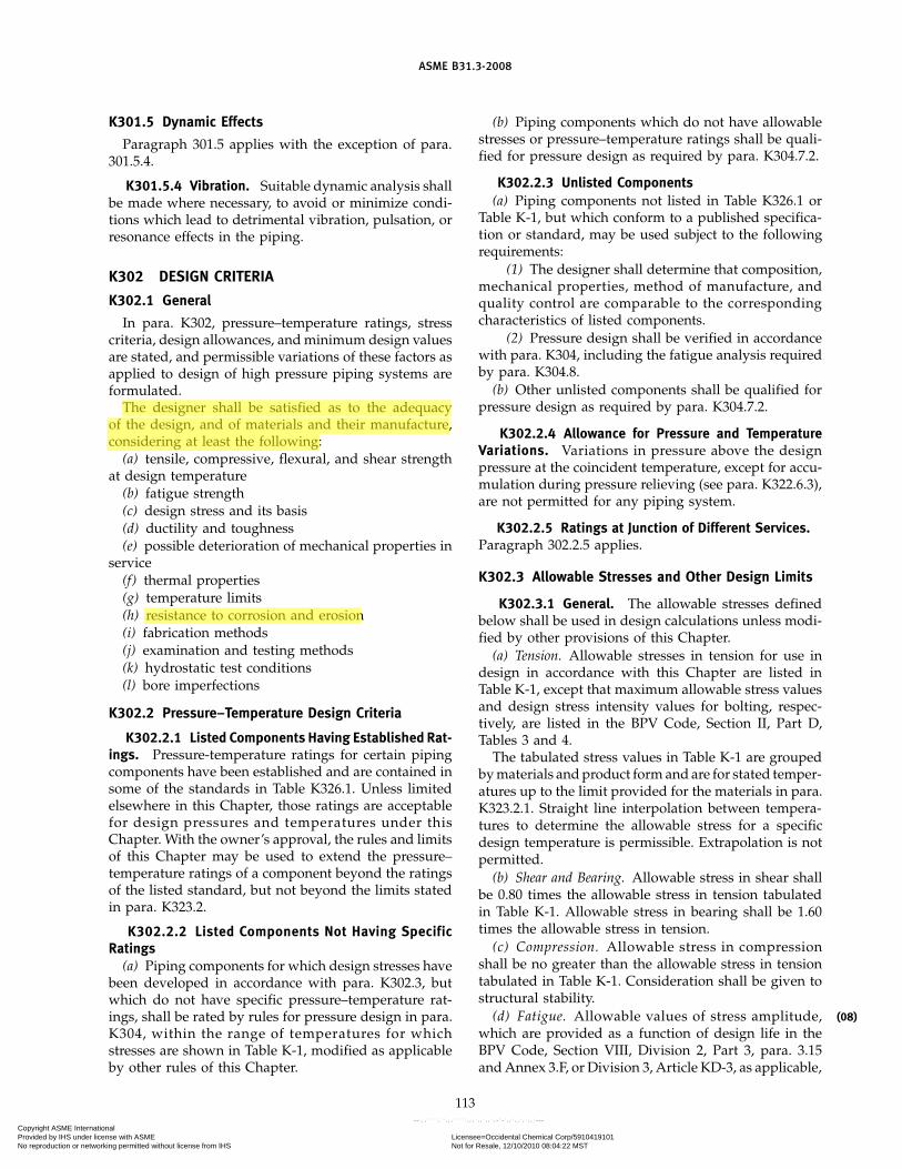
K302.1 General
In para. K302, pressure–temperature ratings, stresscriteria, design allowances, and minimum design valuesare stated, and permissible variations of these factors asapplied to design of high pressure piping systems areformulated.
The designer shall be satisfied as to the adequacyof the design, and of materials and their manufacture,considering at least the following:
(a) tensile, compressive, flexural, and shear strengthat design temperature
(b) fatigue strength(c) design stress and its basis(d) ductility and toughness(e) possible deterioration of mechanical properties in
service(f) thermal properties(g) temperature limits(h) resistance to corrosion and erosion(i) fabrication methods(j) examination and testing methods(k) hydrostatic test conditions(l) bore imperfections
K302.2 Pressure–Temperature Design Criteria
K302.2.1 Listed Components Having Established Rat-ings. Pressure-temperature ratings for certain pipingcomponents have been established and are contained insome of the standards in Table K326.1. Unless limitedelsewhere in this Chapter, those ratings are acceptablefor design pressures and temperatures under thisChapter. With the owner’s approval, the rules and limitsof this Chapter may be used to extend the pressure–temperature ratings of a component beyond the ratingsof the listed standard, but not beyond the limits statedin para. K323.2.
K302.2.2 Listed Components Not Having SpecificRatings
(a) Piping components for which design stresses havebeen developed in accordance with para. K302.3, butwhich do not have specific pressure–temperature rat-ings, shall be rated by rules for pressure design in para.K304, within the range of temperatures for whichstresses are shown in Table K-1, modified as applicableby other rules of this Chapter.
113
(b) Piping components which do not have allowablestresses or pressure–temperature ratings shall be quali-fied for pressure design as required by para. K304.7.2.
K302.2.3 Unlisted Components(a) Piping components not listed in Table K326.1 or
Table K-1, but which conform to a published specifica-tion or standard, may be used subject to the followingrequirements:
(1) The designer shall determine that composition,mechanical properties, method of manufacture, andquality control are comparable to the correspondingcharacteristics of listed components.
(2) Pressure design shall be verified in accordancewith para. K304, including the fatigue analysis requiredby para. K304.8.
(b) Other unlisted components shall be qualified forpressure design as required by para. K304.7.2.
K302.2.4 Allowance for Pressure and TemperatureVariations. Variations in pressure above the designpressure at the coincident temperature, except for accu-mulation during pressure relieving (see para. K322.6.3),are not permitted for any piping system.
K302.2.5 Ratings at Junction of Different Services.Paragraph 302.2.5 applies.
K302.3 Allowable Stresses and Other Design Limits
K302.3.1 General. The allowable stresses definedbelow shall be used in design calculations unless modi-fied by other provisions of this Chapter.
(a) Tension. Allowable stresses in tension for use indesign in accordance with this Chapter are listed inTable K-1, except that maximum allowable stress valuesand design stress intensity values for bolting, respec-tively, are listed in the BPV Code, Section II, Part D,Tables 3 and 4.
The tabulated stress values in Table K-1 are groupedby materials and product form and are for stated temper-atures up to the limit provided for the materials in para.K323.2.1. Straight line interpolation between tempera-tures to determine the allowable stress for a specificdesign temperature is permissible. Extrapolation is notpermitted.
(b) Shear and Bearing. Allowable stress in shear shallbe 0.80 times the allowable stress in tension tabulatedin Table K-1. Allowable stress in bearing shall be 1.60times the allowable stress in tension.
(c) Compression. Allowable stress in compressionshall be no greater than the allowable stress in tensiontabulated in Table K-1. Consideration shall be given tostructural stability.
(d) Fatigue. Allowable values of stress amplitude,which are provided as a function of design life in theBPV Code, Section VIII, Division 2, Part 3, para. 3.15and Annex 3.F, or Division 3, Article KD-3, as applicable,
(08)
Copyright ASME International Provided by IHS under license with ASME Licensee=Occidental Chemical Corp/5910419101
Not for Resale, 12/10/2010 08:04:22 MSTNo reproduction or networking permitted without license from IHS
--`,,````,``,,,`````,,,`,,`,,`,-`-`,,`,,`,`,,`---

ASME B31.3-2008
Table A-1 Basic Allowable Stresses in Tension for Metals1 (Cont’d)Numbers in Parentheses Refer to Notes for Appendix A Tables; Specifications Are ASTM Unless Otherwise Indicated
Specified Min.P-No. or Min. Min.Strength, ksiS-No. Temp., Temp.
Material Spec. No. (5) Grade Notes °F (6) Tensile Yield to 100 200
Low and Intermediate Alloy SteelPipes (2)
1⁄2Cr–1⁄2Mo A 335 3 P2 . . . −20 55 30 18.3 18.31⁄2Cr–1⁄2Mo A 691 3 1⁄2CR (11)(67) −20 55 33 18.3 18.3
A 387 Gr. 2 Cl. 1
C–1⁄2Mo A 335 3 P1C–1⁄2Mo A 369 3 FP1 (58) −20 55 30 18.3 18.31⁄2Cr–1⁄2Mo A 369 3 FP2 . . . −20 55 30 18.3 18.31Cr–1⁄2Mo A 691 4 1CR (11)(67) −20 55 33 18.3 18.3
A 387 Gr. 12 Cl. 1
1⁄2Cr–1⁄2Mo A 426 3 CP2 (10) −20 60 30 18.4 17.711⁄2Si–1⁄2Mo A 335 3 P15 . . .11⁄2Si–1⁄2Mo A 426 3 CP15 (10) −20 60 30 18.8 18.2
1Cr–1⁄2Mo A 426 4 CP12 (10) −20 60 30 18.8 18.3
5Cr–1⁄2Mo–11⁄2Si A 426 5B CP5b (10) −20 60 30 18.8 17.93Cr–Mo A 426 5A CP21 (10) −20 60 30 18.8 18.1
3⁄4Cr–3⁄4Ni–Cu–Al A 333 4 4 . . . −150 60 35 20.0 19.12Cr–1⁄2Mo A 369 4 FP3b . . . −20 60 30 20.0 18.5
1Cr–1⁄2Mo A 335 4 P121Cr–1⁄2Mo A 369 4 FP12 . . . −20 60 32 20.0 18.7
11⁄4Cr–1⁄2Mo A 335 4 P1111⁄4Cr–1⁄2Mo A 369 4 FP11 . . . −20 60 30 20.0 18.7
11⁄4Cr–1⁄2Mo A 691 4 11⁄4CR (11)(67) −20 60 35 20.0 20.0A 387 Gr. 11 Cl. 1
5Cr–1⁄2Mo A 691 5B 5CR (11)(67) −20 60 30 20.0 18.1A 387 Gr. 5 Cl. 1
5Cr–1⁄2Mo A 335 5B P55Cr–1⁄2Mo–Si A 335 5B P5b . . . −20 60 30 20.0 18.15Cr–1⁄2Mo–Ti A 335 5B P5c5Cr–1⁄2Mo A 369 5B FP5
9Cr–1Mo A 335 5B P99Cr–1Mo A 369 5B FP9 . . . −20 60 30 20.0 18.19Cr–1Mo A 691 5B 9CR
A 387 Gr. 9 Cl. 1
3Cr–1Mo A 335 5A P213Cr–1Mo A 369 5A FP21 . . . −20 60 30 20.0 18.7
3Cr–1Mo A 691 5A 3CR (11)(67) −20 60 30 20.0 18.5A 387 Gr. 21 Cl. 1
154
Copyright ASME International Provided by IHS under license with ASME Licensee=Occidental Chemical Corp/5910419101
Not for Resale, 12/10/2010 08:04:22 MSTNo reproduction or networking permitted without license from IHS
--`,,````,``,,,`````,,,`,,`,,`,-`-`,,`,,`,`,,`---
Appendix C
ASTM A335

Designation: A335/A335M – 11
Standard Specification forSeamless Ferritic Alloy-Steel Pipe for High-TemperatureService1
This standard is issued under the fixed designation A335/A335M; the number immediately following the designation indicates the yearof original adoption or, in the case of revision, the year of last revision. A number in parentheses indicates the year of last reapproval.A superscript epsilon (´) indicates an editorial change since the last revision or reapproval.
This standard has been approved for use by agencies of the Department of Defense.
1. Scope*
1.1 This specification2 covers nominal wall and minimumwall seamless ferritic alloy-steel pipe intended for high-temperature service. Pipe ordered to this specification shall besuitable for bending, flanging (vanstoning), and similar form-ing operations, and for fusion welding. Selection will dependupon design, service conditions, mechanical properties, andhigh-temperature characteristics.
1.2 Several grades of ferritic steels (see Note 1) are covered.Their compositions are given in Table 1.
NOTE 1—Ferritic steels in this specification are defined as low- andintermediate-alloy steels containing up to and including 10 % chromium.
1.3 Supplementary requirements (S1 to S7) of an optionalnature are provided. These supplementary requirements call foradditional tests to be made, and when desired, shall be so statedin the order together with the number of such tests required.
1.4 The values stated in either SI units or inch-pound unitsare to be regarded separately as standard. Within the text, theSI units are shown in brackets. The values stated in eachsystem may not be exact equivalents; therefore, each systemshall be used independently of the other. Combining valuesfrom the two systems may result in non-conformance with thestandard. The inch-pound units shall apply unless the “M”designation of this specification is specified in the order.
NOTE 2—The dimensionless designator NPS (nominal pipe size) hasbeen substituted in this standard for such traditional terms as “nominaldiameter,” “size,” and “nominal size.”
2. Referenced Documents
2.1 ASTM Standards:3
A999/A999M Specification for General Requirements forAlloy and Stainless Steel Pipe
E92 Test Method for Vickers Hardness of Metallic Materi-als4
E213 Practice for Ultrasonic Testing of Metal Pipe andTubing
E309 Practice for Eddy-Current Examination of Steel Tu-bular Products Using Magnetic Saturation
E381 Method of Macroetch Testing Steel Bars, Billets,Blooms, and Forgings
E527 Practice for Numbering Metals and Alloys in theUnified Numbering System (UNS)
E570 Practice for Flux Leakage Examination of Ferromag-netic Steel Tubular Products
2.2 ASME Standard:B36.10M Welded and Seamless Wrought Steel Pipe2.3 AWS Specifications5
A5.5/A5.5M Specification for Low-Alloy Steel Electrodesfor Shielded Metal Arc Welding
A5.23/A5.23M Specification for Low-Alloy Steel Elec-trodes and Fluxes for Submerged Arc Welding
A5.28/A5.28M Specification for Low-Alloy Steel Elec-trodes for Gas Shielded Arc Welding
A5.29/A5.29M Low-Alloy Steel Electrodes for Flux CoredArc Welding
2.4 Other Documents:SNT-TC-1A Recommended Practice for Nondestructive
Personnel Qualification and Certification6
SAE J 1086 Practice for Numbering Metals and Alloys(UNS)7
1 This specification is under the jurisdiction of ASTM Committee A01 on Steel,Stainless Steel and Related Alloys and is the direct responsibility of SubcommitteeA01.10 on Stainless and Alloy Steel Tubular Products.
Current edition approved Oct. 1, 2011. Published November 2011. Originallyapproved in 1951. Last previous edition approved in 2010 as A335/A335M–10b.DOI: 10.1520/A0335_A0335M-11.
2 For ASME Boiler and Pressure Vessel Code applications see related Specifi-cation SA-335 in Section II of that Code.
3 For referenced ASTM standards, visit the ASTM website, www.astm.org, orcontact ASTM Customer Service at [email protected]. For Annual Book of ASTMStandards volume information, refer to the standard’s Document Summary page onthe ASTM website.
4 Withdrawn. The last approved version of this historical standard is referencedon www.astm.org.
5 Available from American Welding Society (AWS), 550 NW LeJeune Rd.,Miami, FL 33126, http://www.aws.org.
6 Available from American Society for Nondestructive Testing (ASNT), P.O. Box28518, 1711 Arlingate Ln., Columbus, OH 43228-0518, http://www.asnt.org.
7 Available from SAE International (SAE), 400 Commonwealth Dr., Warrendale,PA 15096-0001, http://www.sae.org.
1
*A Summary of Changes section appears at the end of this standard.
Copyright by ASTM Int'l (all rights reserved);
Copyright. (C) ASTM International, 100 Barr Harbour Dr., P.O. Box C700 West Conshohocken, Pennsylvania United States

TABLE 1 Chemical Requirements
Grade
UNSDesigna-
tionA
Composition, %
CarbonMan-
ganese
Phos-phorus,
max
Sulfur,max
Silicon ChromiumMolybde-
num Others
P1 K11522 0.10–0.20 0.30–0.80 0.025 0.025 0.10–0.50 . . . 0.44–0.65 . . .P2 K11547 0.10–0.20 0.30–0.61 0.025 0.025 0.10–0.30 0.50–0.81 0.44–0.65 . . .P5 K41545 0.15 max 0.30–0.60 0.025 0.025 0.50 max 4.00–6.00 0.45–0.65 . . .
P5b K51545 0.15 max 0.30–0.60 0.025 0.025 1.00–2.00 4.00–6.00 0.45–0.65 . . .P5c K41245 0.12 max 0.30–0.60 0.025 0.025 0.50 max 4.00–6.00 0.45–0.65 . . .B
P9 S50400 0.15 max 0.30–0.60 0.025 0.025 0.25–1.00 8.00–10.00 0.90–1.10 . . .P11 K11597 0.05–0.15 0.30–0.60 0.025 0.025 0.50–1.00 1.00–1.50 0.44–0.65 . . .P12 K11562 0.05–0.15 0.30–0.61 0.025 0.025 0.50 max 0.80–1.25 0.44–0.65 . . .P15 K11578 0.05–0.15 0.30–0.60 0.025 0.025 1.15–1.65 . . . 0.44–0.65 . . .P21 K31545 0.05–0.15 0.30–0.60 0.025 0.025 0.50 max 2.65–3.35 0.80–1.06 . . .P22 K21590 0.05–0.15 0.30–0.60 0.025 0.025 0.50 max 1.90–2.60 0.87–1.13 . . .P23 K41650 0.04–0.10 0.10–0.60 0.030 max 0.010 max 0.50 max 1.90–2.60 0.05–0.30 V 0.20–0.30
Cb 0.02–0.08B 0.0010–0.006
N 0.015 maxAl 0.030 maxW 1.45–1.75Ni 0.40 max
Ti 0.005–0.060Ti/N $ 3.5C
P24 K30736 0.05–0.10 0.30–0.70 0.020 0.010 0.15–0.45 2.20–2.60 0.90–1.10 V 0.20–0.30Ti 0.06–0.10N 0.012 maxAl 0.02 max
B 0.0015–0.007P36 K21001 0.10–0.17 0.80–1.20 0.030 max 0.025 max 0.25–0.50 0.30 max 0.25–0.50 Ni 1.00-1.30
Cu 0.50-0.80Cb 0.015-0.045
V 0.02 maxN 0.02 max
Al 0.050 maxP91 K91560 0.08–0.12 0.30–0.60 0.020 0.010 0.20–0.50 8.00–9.50 0.85–1.05 V 0.18–0.25
N 0.030–0.070Ni 0.40 maxAl 0.02 max
Cb 0.06–0.10Ti 0.01 maxZr 0.01 max
P92 K92460 0.07–0.13 0.30–0.60 0.020 0.010 0.50 max 8.50–9.50 0.30–0.60 V 0.15–0.25N 0.03–0.07Ni 0.40 maxAl 0.02 max
Cb 0.04–0.09W 1.5–2.00
B 0.001–0.006Ti 0.01 maxZr 0.01 max
P122 K92930 0.07–0.14 0.70 max 0.020 0.010 0.50 max 10.00–11.50 0.25–0.60 V 0.15–0.30W 1.50–2.50Cu 0.30–1.70Cb 0.04–0.10
B 0.0005–0.005N 0.040–0.100Ni 0.50 maxAl 0.020 maxTi 0.01 maxZr 0.01 max
P911 K91061 0.09–0.13 0.30–0.60 0.020 max 0.010 max 0.10–0.50 8.5–9.5 0.90–1.10 V 0.18–0.25Ni 0.40 max
Cb 0.060–0.10B 0.0003–0.006
N 0.04–0.09Al 0.02 maxW 0.90–1.10Ti 0.01 maxZr 0.01 max
A New designation established in accordance with Practice E527 and SAE J 1086, Practice for Numbering Metals and Alloys (UNS).B Grade P 5c shall have a titanium content of not less than 4 times the carbon content and not more than 0.70 %; or a columbium content of 8 to 10 times the carbon
content.CAlternatively, in lieu of this ratio minimum, the material shall have a minimum hardness of 275 HV in the hardened condition, defined as after austenitizing and cooling
to room temperature but prior to tempering. Hardness testing shall be performed at mid-thickness of the product. Hardness test frequency shall be two samples of productper heat treatment lot and the hardness testing results shall be reported on the material test report.
A335/A335M – 11
2Copyright by ASTM Int'l (all rights reserved);
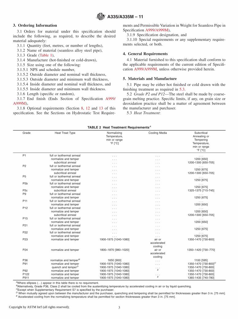
3. Ordering Information
3.1 Orders for material under this specification shouldinclude the following, as required, to describe the desiredmaterial adequately:
3.1.1 Quantity (feet, metres, or number of lengths),3.1.2 Name of material (seamless alloy steel pipe),3.1.3 Grade (Table 1),3.1.4 Manufacture (hot-finished or cold-drawn),3.1.5 Size using one of the following:3.1.5.1 NPS and schedule number,3.1.5.2 Outside diameter and nominal wall thickness,3.1.5.3 Outside diameter and minimum wall thickness,3.1.5.4 Inside diameter and nominal wall thickness, and3.1.5.5 Inside diameter and minimum wall thickness.3.1.6 Length (specific or random),3.1.7 End finish (Ends Section of Specification A999/
A999M),3.1.8 Optional requirements (Section 8, 12 and 13 of this
specification. See the Sections on Hydrostatic Test Require-
ments and Permissible Variation in Weight for Seamless Pipe inSpecification A999/A999M),
3.1.9 Specification designation, and3.1.10 Special requirements or any supplementary require-
ments selected, or both.
4. General Requirements
4.1 Material furnished to this specification shall conform tothe applicable requirements of the current edition of Specifi-cation A999/A999M, unless otherwise provided herein.
5. Materials and Manufacture
5.1 Pipe may be either hot finished or cold drawn with thefinishing treatment as required in 5.3.
5.2 Grade P2 and P12—The steel shall be made by coarse-grain melting practice. Specific limits, if any, on grain size ordeoxidation practice shall be a matter of agreement betweenthe manufacturer and purchaser.
5.3 Heat Treatment:
TABLE 2 Heat Treatment RequirementsA
Grade Heat Treat Type NormalizingTemperature,min or range
°F [°C]
Cooling Media SubcriticalAnnealing orTempering
Temperature,min or range
°F [°C]
P1 full or isothermal anneal . . . . . . . . .normalize and temper . . . . . . 1200 [650]
subcritical anneal . . . . . . 1200-1300 [650-705]P2 full or isothermal anneal . . . . . . . . .
normalize and temper . . . . . . 1250 [675]subcritical anneal . . . . . . 1200-1300 [650-705]
P5 full or isothermal anneal . . . . . . . . .normalize and temper . . . . . . 1250 [675]
P5b full or isothermal anneal . . . . . . . . .normalize and temper . . . . . . 1250 [675]
P5c subcritical anneal . . . . . . 1325-1375 [715-745]P9 full or isothermal anneal . . . . . . . . .
normalize and temper . . . . . . 1250 [675]P11 full or isothermal anneal . . . . . . . . .
normalize and temper . . . . . . 1200 [650]P12 full or isothermal anneal . . . . . . . . .
normalize and temper . . . . . . 1200 [650]subcritical anneal . . . . . . 1200-1300 [650-705]
P15 full or isothermal anneal . . . . . . . . .normalize and temper . . . . . . 1200 [650]
P21 full or isothermal anneal . . . . . . . . .normalize and temper . . . . . . 1250 [675]
P22 full or isothermal anneal . . . . . . . . .normalize and temper . . . . . . 1250 [675]
P23 normalize and temper 1900-1975 [1040-1080] air oraccelerated
cooling
1350-1470 [730-800]
P24 normalize and temper 1800–1870 [980–1020] air oraccelerated
cooling
1350–1420 [730–770]
P36 normalize and temperB 1650 [900] . . . 1100 [595]P91 normalize and temper 1900-1975 [1040-1080] . . . 1350-1470 [730-800]C
quench and temperD 1900-1975 [1040-1080] . . . 1350-1470 [730-800]P92 normalize and temper 1900-1975 [1040-1080] E 1350-1470 [730-800]P122 normalize and temper 1900-1975 [1040-1080] . . . 1350-1470 [730-800]P911 normalize and temper 1900-1975 [1040-1080] E 1365-1435 [740-780]
AWhere ellipses (…) appear in this table there is no requirement.BAlternatively, Grade P36, Class 2 shall be cooled from the austenitizing temperature by accelerated cooling in air or by liquid quenching.CExcept when Supplementary Requirement S7 is specified by the purchaser.D When mutually agreed upon between the manufacturer and the purchaser, quenching and tempering shall be permitted for thicknesses greater than 3 in. [75 mm].E Accelerated cooling from the normalizing temperature shall be permitted for section thicknesses greater than 3 in. [75 mm].
A335/A335M – 11
3Copyright by ASTM Int'l (all rights reserved);

5.3.1 All pipe shall be reheated for heat treatment and heattreated in accordance with the requirements of Table 2.
NOTE 3—It is recommended that the temperature for tempering shouldbe at least 100 °F [50 °C] above the intended service temperature;consequently, the purchaser should advise the manufacturer if the servicetemperature is to be over 1100 °F [600 °C].
NOTE 4—Certain of the ferritic steels covered by this specification willharden if cooled rapidly from above their critical temperature. Some willair harden, that is, become hardened to an undesirable degree when cooledin air from high temperatures. Therefore, operations involving heatingsuch steels above their critical temperatures, such as welding, flanging,and hot bending, should be followed by suitable heat treatment.
6. Chemical Composition
6.1 The steel shall conform to the requirements as tochemical composition prescribed in Table 1.
7. Workmanship, Finish, and Appearance
7.1 The pipe manufacturer shall explore a sufficient numberof visual surface imperfections to provide reasonable assurancethat they have been properly evaluated with respect to depth.Exploration of all surface imperfections is not required but maybe necessary to ensure compliance with 7.2
7.2 Surface imperfections that penetrate more than 121⁄2 %of the nominal wall thickness or encroach on the minimumwall thickness shall be considered defects. Pipe with suchdefects shall be given one of the following dispositions:
7.2.1 The defect may be removed by grinding provided thatthe remaining wall thickness is within specified limits.
7.2.2 Repaired in accordance with the repair welding pro-visions of 7.6.
7.2.3 The section of pipe containing the defect may be cutoff within the limits of requirements on length.
7.2.4 Rejected.7.3 To provide a workmanlike finish and basis for evaluat-
ing conformance with 7.2, the pipe manufacturer shall removeby grinding the following:
7.3.1 Mechanical marks, abrasions (see Note 5) and pits,any of which imperfections are deeper than 1⁄16 in. [1.6 mm].
NOTE 5—Marks and abrasions are defined as cable marks, dinges, guidemarks, roll marks, ball scratches, scores, die marks, and the like.
7.3.2 Visual imperfections, commonly referred to as scabs,seams, laps, tears, or slivers, found by exploration in accor-dance with 7.1 to be deeper than 5 % of the nominal wallthickness.
7.4 At the purchaser’s discretion, pipe shall be subject torejection if surface imperfections acceptable under 7.2 are notscattered, but appear over a large area in excess of what isconsidered a workmanlike finish. Disposition of such pipe shallbe a matter of agreement between the manufacturer and thepurchaser.
7.5 When imperfections or defects are removed by grinding,a smooth curved surface shall be maintained, and the wallthickness shall not be decreased below that permitted by thisspecification. The outside diameter at the point of grinding maybe reduced by the amount so removed.
7.5.1 Wall thickness measurements shall be made with amechanical caliper or with a properly calibrated nondestructivetesting device of appropriate accuracy. In case of dispute, themeasurement determined by use of the mechanical caliper shallgovern.
7.6 Weld repair shall be permitted only subject to theapproval of the purchaser and in accordance with SpecificationA999/A999M.
7.6.1 All repair welds in P91 shall be made with one of thefollowing welding processes and consumables: SMAW, A5.5/A5.5M E90XX-B9; SAW, A5.23/A5.23M EB9 + neutral flux;GTAW, A5.28/A5.28M ER90S-B9; and FCAW A5.29/A5.29ME91T1-B9. In addition, the sum of the Ni+Mn content of allwelding consumables used to weld repair P91 shall not exceed1.0 %.
7.6.2 All repair welds in P92, P911, and P122, shall be madeusing welding consumables meeting the chemical requirementsfor the grade in Table 1.
7.6.3 After weld repair, Grades P23, P91, P92, and P122shall be heat treated at 1350-1470 ºF [730-800 ºC].
7.6.4 After weld repair, Grade P911 shall be heat treated at1365-1435 ºF [740-780 ºC].
7.6.5 After weld repair, Grade P24 shall be heat treated at1350-1420 °F [730-770 °C].
7.7 The finished pipe shall be reasonably straight.
8. Product Analysis
8.1 At the request of the purchaser, an analysis of two pipesfrom each lot as defined hereafter shall be made by themanufacturer. A lot is all pipe of the same nominal size andwall thickness (schedule) which is produced from the sameheat of steel and shall be limited as follows:
NPS Designator Maximum Number ofLengths in a Lot
Under 2 4002 to 5 2006 and over 100
8.2 The results of these analyses shall be reported to thepurchaser or the purchaser’s representative, and shall conformto the requirements specified in Table 1.
8.3 For grade P 91 the carbon content may vary for theproduct analysis by −0.01 % and +0.02 % from the specifiedrange as per Table 1.
8.4 If the analysis of one of the tests specified in 8.1 doesnot conform to the requirements specified in 6.1, an analysis ofeach billet or pipe from the same heat or lot may be made, andall billets or pipe conforming to the requirements shall beaccepted.
9. Tensile and Hardness Requirements
9.1 The tensile properties of the material shall conform tothe requirements prescribed in Table 3.
9.2 Table 4 lists elongation requirements.9.3 Pipe of Grade P91 shall have a hardness inclusively in
the range 190 to 250 HBW/196 to 265 HV [91 HRB to 25HRC]. Pipe of Grades P24, P92, P122, and P36 shall have ahardness not exceeding 250 HBW/265 HV30 [25 HRC].
9.4 Table 5 gives the computed minimum elongation valuesfor each 1⁄32-in. [0.8-mm] decrease in wall thickness. Where the
A335/A335M – 11
4Copyright by ASTM Int'l (all rights reserved);

wall thickness lies between two values above, the minimumelongation value is determined by the following formula:
Direction of Test EquationB
Longitudinal, all grades except P23, P91,P92, P122, and P911
E = 48t + 15.00[E = 1.87t + 15.00]
Transverse, all grades except P23, P91,P92, P122, and P911
E = 32t + 10.00[E = 1.25t + 10.00]
Longitudinal, P23, P24, P91, P92, P122,and P911
E = 32t + 10.00[E = 1.25t + 10.00]
Longitudinal, P36 E = 32t + 5.0[E = 1.25t + 5.0]
where:E = elongation in 2 in. or 50 mm, %, andt = actual thickness of specimens, in. [mm].
9.5 For Grade P91, when quenching and tempering has beenagreed upon in accordance with Note D in Table 2, the tensile
and hardness properties shall be met and verified on materialtaken from the half-thickness location.
10. Permissible Variations in Diameter
10.1 For pipe ordered to NPS [DN] or outside diameter,variations in outside diameter shall not exceed those specifiedin Table 6.
10.2 For pipe ordered to inside diameter, the inside diametershall not vary more than 6 1 % from the specified insidediameter.
11. Permissible Variations in Wall Thickness
11.1 In addition to the implicit limitation of wall thicknessfor pipe imposed by the limitation on weight in SpecificationA999/A999M, the wall thickness for pipe at any point shall bewithin the tolerances specified in Table 7. The minimum wallthickness and outside diameter for inspection for compliancewith this requirement for pipe ordered by NPS [DN] andschedule number is shown in ASME B36.10M.
12. Hydrostatic Test
12.1 The requirements for grades other than P91, P92, P911,and P122 are shown in 12.1.1-12.1.4.
12.1.1 Each length of pipe with outside diameter greaterthan 10 in. [250 mm] and wall thickness less than or equal to0.75 in. [19 mm], shall be submitted to the hydrostatic test,except as provided for in 12.1.4.
12.1.2 Pipe of all other sizes shall be subjected to thenondestructive electric test as shown in Section 13, except asprovided for in 12.1.3 and 12.1.4.
12.1.3 When specified by the purchaser, pipe of all othersizes shall be furnished without the hydrostatic test and withoutnondestructive examination.
12.1.4 When specified by the purchaser, pipe shall befurnished with both the hydrostatic test and a nondestructiveexamination having been performed.
12.2 The requirements for grades P91, P92, P911, and P122are shown in 12.2.1-12.2.3.
12.2.1 Each length of pipe with outside diameter greaterthan 10 in. [250 mm] and wall thickness less than or equal to0.75 in. [19 mm], shall be submitted to both the hydrostatic testand the ultrasonic test as shown in Section 13.
TABLE 3 Tensile Requirements
Grade
P1, P2 P12 P23 P24 P91P92, P911
P36 Class 1P122 P36 Class 2 All Others
Tensile strength,min:
ksiMPa
55380
60415
74510
85585
85585
90620
90620
95.5660
60415
Yield strength,min:
ksiMPa
30205
32220
58400
60415
60415
64440
58400
66.5460
30205
TABLE 4 Elongation Requirements
Elongation Requirements
All gradesexcept P23, P36P91, P92, P122,
and P911
P23, P24, P91,P92, P122, and
P 911 P36
Longi-tudi-nal
Trans-verse
Longi-tudi-nal
Trans-verse
Longi-tudi-nal
Elongation in 2 in. or 50 mm,(or 4D), min, %:Basic minimum elongationfor wall 5⁄16 in. [8 mm] andover in thickness, strip tests,and for all small sizes testedin full section
30 20 20 . . . 15
When standard round 2-in.or 50-mm gage length orproportionally smaller sizespecimen with the gagelength equal to 4D (4 timesthe diameter) is used
22 14 20 13 . . .
For strip tests a deductionfor each 1⁄32-in. [0.8 mm]decrease in wall thicknessbelow in. [8 mm] from thebasic minimum elongation ofthe following percentagepoints shall be made
1.50A 1.00A 1.00A . . . 1.00A
A Table 5 gives the calculated minimum values.
A335/A335M – 11
5Copyright by ASTM Int'l (all rights reserved);

12.2.2 Pipe of all other sizes shall be subjected to thenondestructive electric test as shown in Section 13, except asprovided for in 12.2.3.
12.2.3 When specified by the purchaser, pipe of all othersizes shall be furnished with both the hydrostatic test and anondestructive examination having been performed.
13. Nondestructive Examination
13.1 When required by 12.1.2 or 12.2 above, or whenspecified in the purchase order in addition to the hydrostatictest (12.2.3), each pipe shall be examined by a nondestructiveexamination method in accordance with Practice E213, Prac-tice E309, or Practice E570. Except for Grades P91, P92, P911,and P122, the type of nondestructive examination shall be atthe option of the manufacturer, unless otherwise specified inthe order. Grades P91, P92, P911, and P122 shall be examinedby an examination method in accordance with Practice E213.When specified in the order, pipe of Grades P91, P92, P911,and P122 shall be examined by an examination method inaccordance with Practices E309 or E570, in addition to theexamination method in accordance with Practice E213. The
range of pipe sizes that may be examined by each method shallbe subject to the limitations in the scope of the respectivepractices.
13.2 Following conditions apply in lieu or in addition tothose in Specification A999/A999M:
13.2.1 The width of the notch shall not exceed the depth.13.2.2 If upon any standardization, the reference signal
amplitude has decreased by more than 25 % (2 db), the testapparatus shall be considered out of standardization. The testsystem settings may be changed, or the transducer(s), coil(s) orsensor(s) adjusted, and the unit restandardized, but all pipetested since the last acceptable standardization shall be re-tested.
13.2.3 Pipes producing a signal equal to or greater than thesignal produced by the reference standard shall be subject toone of the following four dispositions:
13.2.3.1 The pipes may be rejected without further exami-nation, at the discretion of the manufacturer.
13.2.3.2 The pipes shall be rejected if the test signal wasproduced by imperfections which cannot be identified, or wasproduced by cracks or crack-like imperfections.
13.2.3.3 The pipes may be repaired by grinding (in accor-dance with 7.2.1), welding (in accordance with 7.6) or section-ing (in accordance with 7.2.3). To be accepted, a repaired pipemust pass the same nondestructive examination by which itwas rejected, and it must meet the remaining wall thicknessrequirements of this specification.
13.2.3.4 If the test signals were produced by visual imper-fections such as those listed below, the pipes may be evaluatedin accordance with the provisions of Section 7:
(a) Scratches,(b) Surface roughness,(c) Dings,(d) Straightener marks,(e) Cutting chips,(f) Steel die stamps,(g) Stop marks, or(h) Pipe reducer ripple.
14. Mechanical Tests Required
14.1 Lot—For mechanical testing, a lot is all pipe of thesame nominal size and wall thickness (or schedule) which isproduced from the same heat of steel and subjected to the same
TABLE 5 Calculated Minimum Elongation Values
Wall Thickness
Elongation in 2 in. or 50 mm, min, %
All grades except P23, P36,P91, P92, P122, and P911
P23, P24, P91,P92, P122,and P911
P36
in. mmLongi-tudinal
TransverseLongi-tudinal
Longi-tudinal
5⁄16 (0.312) 8 30 20 20 159⁄32 (0.281) 7.2 28 19 19 141⁄4 (0.250) 6.4 27 18 18 137⁄32 (0.219) 5.6 26 . . . 17 123⁄16 (0.188) 4.8 24 . . . 16 115⁄32 (0.156) 4 22 . . . 15 101⁄8 (0.125) 3.2 21 . . . 14 93⁄32 (0.094) 2.4 20 . . . 13 81⁄16 (0.062) 1.6 18 . . . 12 7
TABLE 6 Permissible Variations in Outside Diameter
Over Under
NPS [DN] Designator in. mm in. mm
1⁄8 to 11⁄2 [6 to 40], incl. 1⁄64 (0.015) 0.40 1⁄64 (0.015) 0.40Over 11⁄2 to 4 [40 to 100],incl.
1⁄32 (0.031) 0.79 1⁄32 (0.031) 0.79
Over 4 to 8 [100 to 200],incl.
1⁄16 (0.062) 1.59 1⁄32 (0.031) 0.79
Over 8 to 12 [200 to 300],incl.
3⁄32 (0.093) 2.38 1⁄32 (0.031) 0.79
Over 12 [300] 6 1 % of thespecifiedoutsidediameter
TABLE 7 Permitted Variations in Wall Thickness
NPS [DN] Designator Tolerance, % from Specified
Over Under
1⁄8 to 21⁄2 [6 to 65] incl., all t/D ratiosA 20.0 12.5Above 21⁄2 [65], t/D # 5 %A 22.5 12.5Above 21⁄2 [65], t/D > 5 %A 15.0 12.5A t = Specified Wall Thickness; D = Specified Outside Diameter.
A335/A335M – 11
6Copyright by ASTM Int'l (all rights reserved);
finishing treatment in a continuous furnace; when final heattreatment is in a batch-type furnace, the lot shall include onlythat pipe which is heat treated in the same furnace charge.
14.2 Transverse or Longitudinal Tension Test and Flatten-ing Test, Hardness Test, or Bend Test—For material heattreated in a batch-type furnace, tests shall be made on 5 % ofthe pipe from each treated lot. For small lots, at least 1 pipeshall be tested. For material heat treated by the continuousprocess, tests shall be made on a sufficient number of pipe toconstitute 5 % of the lot, but in no case less than 2 pipe.
14.3 Hardness Test:14.3.1 The Vickers hardness testing shall be made in accor-
dance with Test Method E92.14.3.2 For pipes with wall thickness 0.200 in [5.1 mm] or
over, either the Brinell or Rockwell hardness test shall be used.When Brinell hardness testing is used, a 10-mm ball with 3000,1500, or 500-kg load shall be used at the option of themanufacturer.
14.3.3 For pipes with wall thickness 0.065 in. [1.7 mm] orover, but less than 0.200 in [5.1 mm], the Rockwell hardnesstest shall be used.
14.3.4 For pipes with wall thickness less than 0.065 in [1.7mm], the hardness test shall not be required.
14.3.5 The Brinell test shall be made, at the option of themanufacturer, on the outside of the pipe near the end, on theoutside of a specimen cut from the pipe, or on the wall crosssection of a specimen cut from the pipe. This test shall be madeso that the center of the impression to the edge of the specimenis at least 2.5 times the diameter of the impression.
14.3.6 The Rockwell hardness test shall, at the option of themanufacturer, be made on the inside surface, on the wall crosssection, or on a flat of the outside surface.
14.3.7 For pipe of Grades P24, P91, P92, P122, P911, andP36, Brinell, Vickers, or Rockwell hardness tests shall be madeon a specimen from each lot.
14.4 Bend Test:14.4.1 For pipe whose diameter exceeds NPS 25 and whose
diameter to wall thickness ratio is 7.0 or less shall be subjectedto the bend test instead of the flattening test. Other pipe whosediameter equals or exceeds NPS 10 may be given the bend testin place of the flattening test subject to the approval of thepurchaser.
14.4.2 The bend test specimens shall be bent at roomtemperature through 180° without cracking on the outside ofthe bent portion. The inside diameter of the bend shall be 1 in.[25 mm].
14.4.3 Test specimens for the bend test specified in 14.4shall be cut from one end of the pipe and, unless otherwisespecified, shall be taken in a transverse direction. One testspecimen shall be taken as close to the outer surface as possible
and another from as close to the inner surface as possible. Thespecimens shall be either 1⁄2 by 1⁄2 in. [12.5 by 12.5 mm] insection or 1 by 1⁄2 in. [25 by 12.5 mm] in section with thecorners rounded to a radius not over 1⁄16 in. [1.6 mm] and neednot exceed 6 in. [150 mm] in length. The side of the samplesplaced in tension during the bend shall be the side closest to theinner and outer surface of the pipe, respectively.
15. Certification
15.1 Certification and test reports, as described in Section25 of Specification A999/A999M, are required.
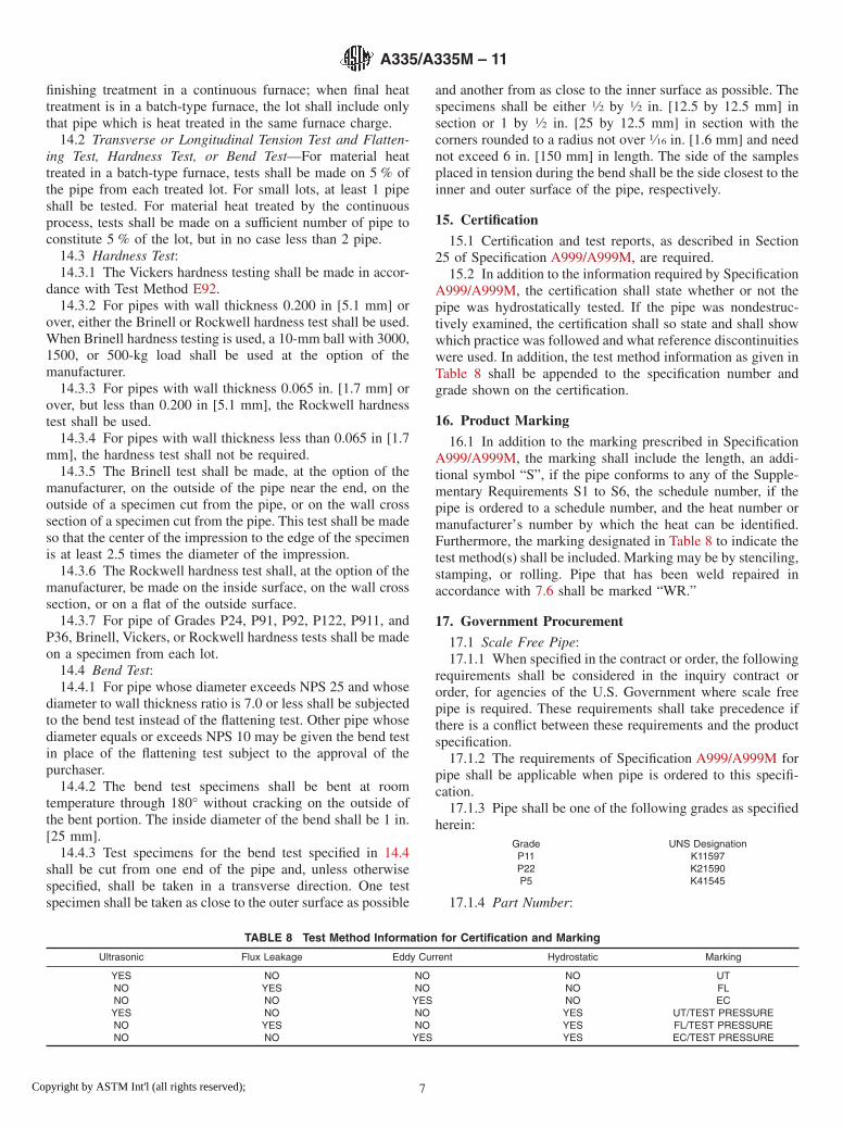
15.2 In addition to the information required by SpecificationA999/A999M, the certification shall state whether or not thepipe was hydrostatically tested. If the pipe was nondestruc-tively examined, the certification shall so state and shall showwhich practice was followed and what reference discontinuitieswere used. In addition, the test method information as given inTable 8 shall be appended to the specification number andgrade shown on the certification.
16. Product Marking
16.1 In addition to the marking prescribed in SpecificationA999/A999M, the marking shall include the length, an addi-tional symbol “S”, if the pipe conforms to any of the Supple-mentary Requirements S1 to S6, the schedule number, if thepipe is ordered to a schedule number, and the heat number ormanufacturer’s number by which the heat can be identified.Furthermore, the marking designated in Table 8 to indicate thetest method(s) shall be included. Marking may be by stenciling,stamping, or rolling. Pipe that has been weld repaired inaccordance with 7.6 shall be marked “WR.”
17. Government Procurement
17.1 Scale Free Pipe:17.1.1 When specified in the contract or order, the following
requirements shall be considered in the inquiry contract ororder, for agencies of the U.S. Government where scale freepipe is required. These requirements shall take precedence ifthere is a conflict between these requirements and the productspecification.
17.1.2 The requirements of Specification A999/A999M forpipe shall be applicable when pipe is ordered to this specifi-cation.
17.1.3 Pipe shall be one of the following grades as specifiedherein:
Grade UNS DesignationP11 K11597P22 K21590P5 K41545
17.1.4 Part Number:
TABLE 8 Test Method Information for Certification and Marking
Ultrasonic Flux Leakage Eddy Current Hydrostatic Marking
YES NO NO NO UTNO YES NO NO FLNO NO YES NO ECYES NO NO YES UT/TEST PRESSURENO YES NO YES FL/TEST PRESSURENO NO YES YES EC/TEST PRESSURE
A335/A335M – 11
7Copyright by ASTM Int'l (all rights reserved);
17.1.4.1 Pipe shall be ordered to nominal pipe size andschedule specified in ASME B36.10MExample: A335/A335M Pipe P-11 NPS 12 Sch 40
Specification Number ASTM A335/A335MPipe PGrade P-11NPS 12Wall 0.375
17.1.4.2Specification Number ASTM A335/A 335 MTube TGrade P-11Outside Diameter 0.250Wall 0.035
17.1.5 Ordering Information—Orders for material underthis specification shall include the following in addition to therequirements of Section 3:
17.1.5.1 Pipe or tube,17.1.5.2 Part number,17.1.5.3 Ultrasonic inspection, if required,17.1.5.4 If shear wave test is to be conducted in two
opposite circumferential directions, and17.1.5.5 Level of preservation and packing required.
18. Keywords
18.1 alloy steel pipe; high temperature service; seamlesssteel pipe; steel pipe; temperature service applications
SUPPLEMENTARY REQUIREMENTS
One or more of the following supplementary requirements shall apply only when specified in thepurchase order. The purchaser may specify a different frequency of test or analysis than is providedin the supplementary requirement. Subject to agreement between the purchaser and manufacturer,retest and retreatment provisions of these supplementary requirements may also be modified.
S1. Product Analysis
S1.1 Product analysis shall be made on each length of pipe.Individual lengths failing to conform to the chemical compo-sition requirements shall be rejected.
S2. Transverse Tension Tests
S2.1 A transverse tension test shall be made on a specimenfrom one end or both ends of each pipe NPS 8 and over. If thissupplementary requirement is specified, the number of tests perpipe shall also be specified. If a specimen from any length failsto meet the required tensile properties (tensile, yield, andelongation), that length shall be rejected subject to retreatmentin accordance with Specification A999/A999M and satisfactoryretest.
S3. Flattening Test
S3.1 The flattening test of Specification A999/A999M shallbe made on a specimen from one end or both ends of each pipe.Crop ends may be used. If this supplementary requirement isspecified, the number of tests per pipe shall also be specified.If a specimen from any length fails because of lack of ductilityprior to satisfactory completion of the first step of the flatteningtest requirement, that pipe shall be rejected subject to retreat-ment in accordance with Specification A999/A999M andsatisfactory retest. If a specimen from any length of pipe failsbecause of a lack of soundness that length shall be rejected,unless subsequent retesting indicates that the remaining lengthis sound. The bend test of 13.2 shall be substituted for theflattening test for pipe whose diameter exceeds NPS 25 andwhose diameter to wall thickness ratio is 7.0 or less.
S4. Metal Structure and Etching Tests
S4.1 The steel shall be homogeneous as shown by etchingtests conducted in accordance with the appropriate portions ofMethod E381. Etching tests shall be made on a cross sectionfrom one end or both ends of each pipe and shall show sound
and reasonably uniform material free from injurious lamina-tions, cracks, and similar objectionable defects. If this supple-mentary requirement is specified, the number of tests per piperequired shall also be specified. If a specimen from any lengthshows objectionable defects, the length shall be rejected,subject to removal of the defective end and subsequent retestsindicating the remainder of the length to be sound andreasonably uniform material.
NOTE S4.1—Pending development of etching methods applicable to theproduct covered by this specification, it is recommended that the Recom-mended Practice for a Standard Macro Etch Test for Routine Inspection ofIron and Steel, described in the Metals Handbook, Am. Soc. for Metals,1948 edition, p. 389, be followed.
S5. Photomicrographs
S5.1 When requested by the purchaser and so stated in theorder, the manufacturer shall furnish one photomicrograph at100 diameters from a specimen of pipe in the as-finishedcondition for each individual size and wall thickness from eachheat, for pipe NPS 3 and over. Such photomicrographs shall besuitably identified as to pipe size, wall thickness, and heat. Nophotomicrographs for the individual pieces purchased shall berequired except as specified in Supplementary Requirement S6.Such photomicrographs are for information only, to show theactual metal structure of the pipe as finished.
S6. Photomicrographs for Individual Pieces
S6.1 In addition to the photomicrographs required in accor-dance with Supplementary Requirement S5, the purchaser mayspecify that photomicrographs shall be furnished from eachend of one or more pipes from each lot of pipe NPS 3 andlarger in the as-finished condition. The purchaser shall state inthe order the number of pipes to be tested from each lot. Whenphotomicrographs are required on each length, the photomi-crographs from each lot of pipe in the as-finished conditionwhich may be required under Supplementary Requirement S5
A335/A335M – 11
8Copyright by ASTM Int'l (all rights reserved);

may be omitted. All photo-micrographs required shall beproperly identified as to heat number, size, and wall thicknessof pipe from which the section was taken. Photomicrographsshall be further identified to permit association of each photo-micrograph with the individual length of pipe it represents.
S7. Alternative Heat Treatment—Grade P91
S7.1 Grade P91 shall be normalized in accordance withTable 2 and tempered at a temperature, to be specified by the
purchaser, less than 1350 °F [730 °C]. It shall be purchaser’sresponsibility to subsequently temper at 1350-1470 °F [730-800 °C] minimum. All mechanical tests shall be made onmaterial heat treated in accordance with Table 2. The certifi-cation shall reference this supplementary requirement indicat-ing the tempering temperature applied. The notation “S7” shallbe included with the required marking of the pipe.
SUMMARY OF CHANGES
Committee A01 has identified the location of selected changes to this specification since the last issue,A335/A335M–10b, that may impact the use of this specification. (Approved October 1, 2011)
(1) Added new 2.3 to Referenced Documents to add AWSspecifications and renumbered subsequent paragraphs.
(2) Inserted new 7.6.1 and 7.6.2 to add process and consumablechemistry restrictions for P91 weld repairs and weld consum-able chemistry restrictions for P92, P122, and P911, andrenumbered subsequent paragraphs.
Committee A01 has identified the location of selected changes to this specification since the last issue,A335/A335M–10a, that may impact the use of this specification. (Approved November 1, 2010)
(1) Rewrote Section 12 Hydrostatic Test and Section 13Nondestructive Examination, thus making the nondestructivetest mandatory and the hydrotest optional. Revised Table 8 toensure coherence with these changes.
(2) Modified the chemical composition of grade P23 in Table 1.
Committee A01 has identified the location of selected changes to this specification since the last issue,A335/A335M–10, that may impact the use of this specification. (Approved May 1, 2010)
(1) Added new 9.5 dealing with compliance of the tensile andhardness properties at mid-thickness for Grade P91 quenchedand tempered.
(2) Added a citation for Footnote E to Grade P92 in Table 2.
(3) Added new Grade P24 to 7.6.5, 9.3, 14.3.7, and Tables 1-5.
Committee A01 has identified the location of selected changes to this specification since the last issue,A335/A335M–09a, that may impact the use of this specification. (Approved April 1, 2010)
(1) Added new 15.1 to make the certification and test reportsmandatory in all cases and renumbered subsequent paragraphs.(2) Revised 14.3 to permit performance of the hardness testing.
(3) Moved the text of Notes 6 and 7 into the main body of thestandard.
ASTM International takes no position respecting the validity of any patent rights asserted in connection with any item mentionedin this standard. Users of this standard are expressly advised that determination of the validity of any such patent rights, and the riskof infringement of such rights, are entirely their own responsibility.
This standard is subject to revision at any time by the responsible technical committee and must be reviewed every five years andif not revised, either reapproved or withdrawn. Your comments are invited either for revision of this standard or for additional standardsand should be addressed to ASTM International Headquarters. Your comments will receive careful consideration at a meeting of theresponsible technical committee, which you may attend. If you feel that your comments have not received a fair hearing you shouldmake your views known to the ASTM Committee on Standards, at the address shown below.
This standard is copyrighted by ASTM International, 100 Barr Harbor Drive, PO Box C700, West Conshohocken, PA 19428-2959,United States. Individual reprints (single or multiple copies) of this standard may be obtained by contacting ASTM at the aboveaddress or at 610-832-9585 (phone), 610-832-9555 (fax), or [email protected] (e-mail); or through the ASTM website(www.astm.org). Permission rights to photocopy the standard may also be secured from the ASTM website (www.astm.org/COPYRIGHT/).
A335/A335M – 11
9Copyright by ASTM Int'l (all rights reserved);

Appendix D
NFPA 30 Excerpts
