dear beneteau owner, - boatlinkmalta.com beneteau owner, it is with great pleasure that we welcome...
TRANSCRIPT
Dear Beneteau Owner, It is with great pleasure that we welcome you to the family of Beneteau boat owners! We sincerely hope that your new Beneteau will offer you, your family, and your guests many hours of pleasant and safe sailing. Your support of our product is greatly appreciated, and we are confident that your new yacht will fulfill all your expectations of a finely crafted vessel. Our dealer network, supported by our Customer Service Department, will gladly attempt to answer any questions and they will provide advice and guidance on any problems that you may have. Once again, thank you, and we wish you as much pleasure sailing your boat as we had in building her for you. Sincerely,
Annette Roux Chief Executive Officer Chantiers Beneteau, S.A., France

BENETEAU HISTORY
For more than a century, the Beneteau family has been building boats. In the beginning, we built commercial fishing boats that were as robust as the fisherman who sailed on them. These boats ventured out to sea no matter what the weather, because their owners relied on them for their livelihood. These craft were built to last; like today's Beneteau's.
At Beneteau the sea is at the roots of our family tree. This is a story of love, commitment and long-standing tradition. From my grandfather to his descendants who operate the company today, we have always been innovative. Yet despite this constant quest for innovation, we have always built boats that are strong. Times have changed, composites have replaced oak, sailing has become a sport, but the sea has remained unchanged, and the sea will always demand the best.
I have always remained true to my family's philosophy of building strength into our products. I will always strive to keep the edge that my ancestors gained on the rest of the boating industry. By giving free rein to innovative talents, constantly improving building techniques, testing every idea in the most severe conditions, our boats will continue to evolve and to improve.
When you are a leader you must show the way. As the world leader in sailboat building, Beneteau will continue to lead the way for pleasure boating in the future.
Annette Roux Chief Executive Officer Chantiers Beneteau, S.A., France
6/12/2008 9:08 AM
Oceanis 381 Rev. 01
I
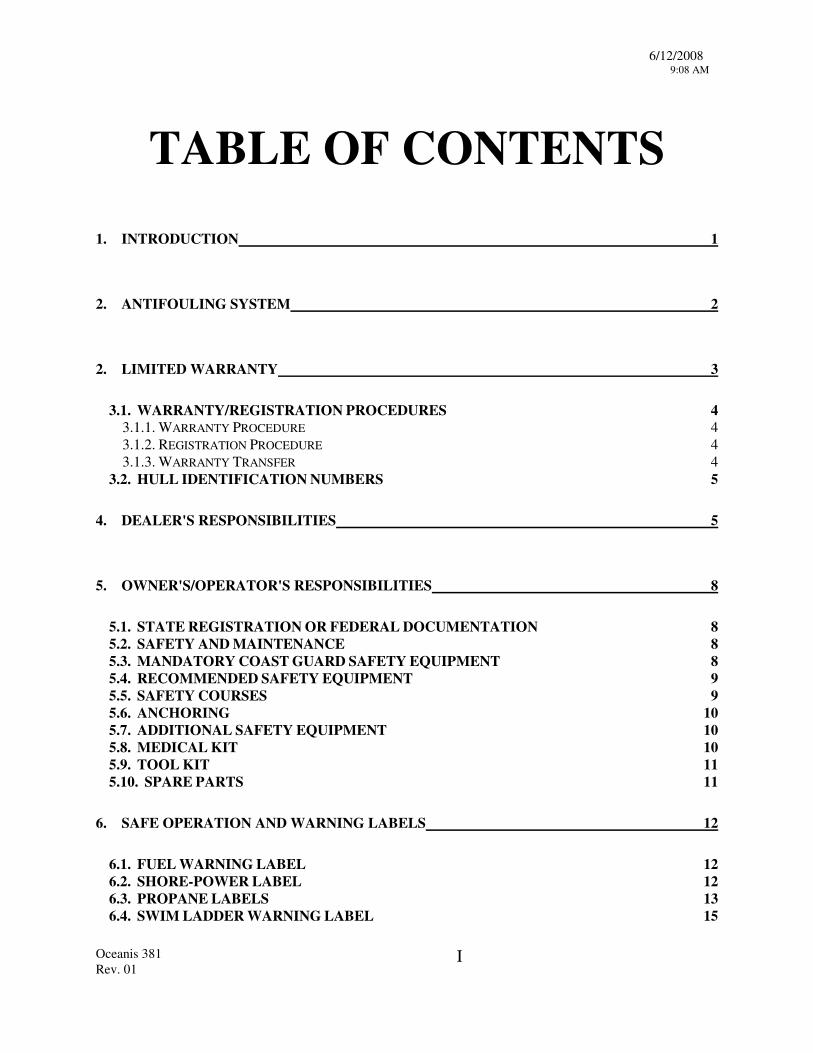
TABLE OF CONTENTS
1. INTRODUCTION 1
2. ANTIFOULING SYSTEM 2
2. LIMITED WARRANTY 3
3.1. WARRANTY/REGISTRATION PROCEDURES 4 3.1.1. WARRANTY PROCEDURE 4 3.1.2. REGISTRATION PROCEDURE 4 3.1.3. WARRANTY TRANSFER 4
3.2. HULL IDENTIFICATION NUMBERS 5
4. DEALER'S RESPONSIBILITIES 5
5. OWNER'S/OPERATOR'S RESPONSIBILITIES 8
5.1. STATE REGISTRATION OR FEDERAL DOCUMENTATION 8 5.2. SAFETY AND MAINTENANCE 8 5.3. MANDATORY COAST GUARD SAFETY EQUIPMENT 8 5.4. RECOMMENDED SAFETY EQUIPMENT 9 5.5. SAFETY COURSES 9 5.6. ANCHORING 10 5.7. ADDITIONAL SAFETY EQUIPMENT 10 5.8. MEDICAL KIT 10 5.9. TOOL KIT 11 5.10. SPARE PARTS 11
6. SAFE OPERATION AND WARNING LABELS 12
6.1. FUEL WARNING LABEL 12 6.2. SHORE-POWER LABEL 12 6.3. PROPANE LABELS 13 6.4. SWIM LADDER WARNING LABEL 15
6/12/2008 9:08 AM
Oceanis 381 Rev. 01
II
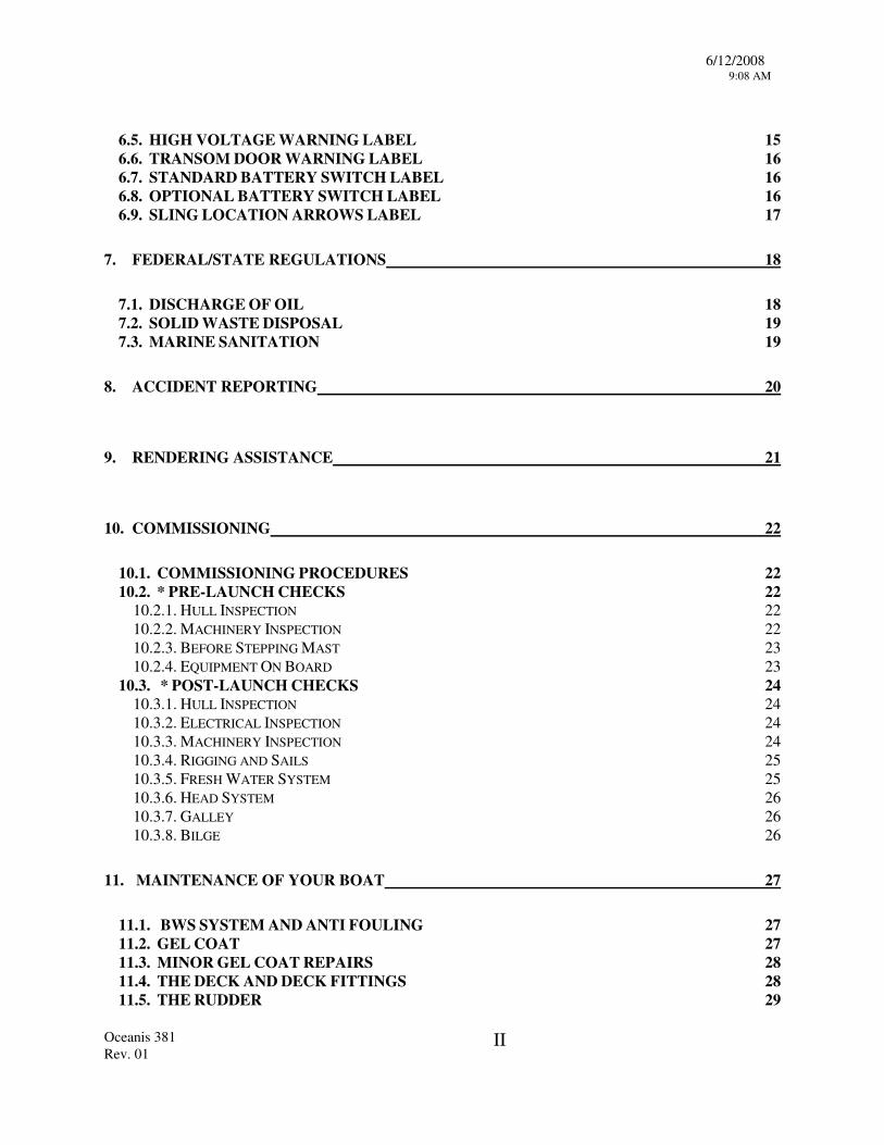
6.5. HIGH VOLTAGE WARNING LABEL 15 6.6. TRANSOM DOOR WARNING LABEL 16 6.7. STANDARD BATTERY SWITCH LABEL 16 6.8. OPTIONAL BATTERY SWITCH LABEL 16 6.9. SLING LOCATION ARROWS LABEL 17
7. FEDERAL/STATE REGULATIONS 18
7.1. DISCHARGE OF OIL 18 7.2. SOLID WASTE DISPOSAL 19 7.3. MARINE SANITATION 19
8. ACCIDENT REPORTING 20
9. RENDERING ASSISTANCE 21
10. COMMISSIONING 22
10.1. COMMISSIONING PROCEDURES 22 10.2. * PRE-LAUNCH CHECKS 22
10.2.1. HULL INSPECTION 22 10.2.2. MACHINERY INSPECTION 22 10.2.3. BEFORE STEPPING MAST 23 10.2.4. EQUIPMENT ON BOARD 23
10.3. * POST-LAUNCH CHECKS 24 10.3.1. HULL INSPECTION 24 10.3.2. ELECTRICAL INSPECTION 24 10.3.3. MACHINERY INSPECTION 24 10.3.4. RIGGING AND SAILS 25 10.3.5. FRESH WATER SYSTEM 25 10.3.6. HEAD SYSTEM 26 10.3.7. GALLEY 26 10.3.8. BILGE 26
11. MAINTENANCE OF YOUR BOAT 27
11.1. BWS SYSTEM AND ANTI FOULING 27 11.2. GEL COAT 27 11.3. MINOR GEL COAT REPAIRS 28 11.4. THE DECK AND DECK FITTINGS 28 11.5. THE RUDDER 29
6/12/2008 9:08 AM
Oceanis 381 Rev. 01
III
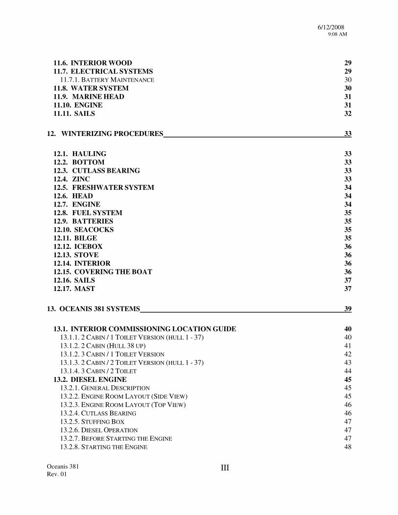
11.6. INTERIOR WOOD 29 11.7. ELECTRICAL SYSTEMS 29
11.7.1. BATTERY MAINTENANCE 30 11.8. WATER SYSTEM 30 11.9. MARINE HEAD 31 11.10. ENGINE 31 11.11. SAILS 32
12. WINTERIZING PROCEDURES 33
12.1. HAULING 33 12.2. BOTTOM 33 12.3. CUTLASS BEARING 33 12.4. ZINC 33 12.5. FRESHWATER SYSTEM 34 12.6. HEAD 34 12.7. ENGINE 34 12.8. FUEL SYSTEM 35 12.9. BATTERIES 35 12.10. SEACOCKS 35 12.11. BILGE 35 12.12. ICEBOX 36 12.13. STOVE 36 12.14. INTERIOR 36 12.15. COVERING THE BOAT 36 12.16. SAILS 37 12.17. MAST 37
13. OCEANIS 381 SYSTEMS 39
13.1. INTERIOR COMMISSIONING LOCATION GUIDE 40 13.1.1. 2 CABIN / 1 TOILET VERSION (HULL 1 - 37) 40 13.1.2. 2 CABIN (HULL 38 UP) 41 13.1.2. 3 CABIN / 1 TOILET VERSION 42 13.1.3. 2 CABIN / 2 TOILET VERSION (HULL 1 - 37) 43 13.1.4. 3 CABIN / 2 TOILET 44
13.2. DIESEL ENGINE 45 13.2.1. GENERAL DESCRIPTION 45 13.2.2. ENGINE ROOM LAYOUT (SIDE VIEW) 45 13.2.3. ENGINE ROOM LAYOUT (TOP VIEW) 46 13.2.4. CUTLASS BEARING 46 13.2.5. STUFFING BOX 47 13.2.6. DIESEL OPERATION 47 13.2.7. BEFORE STARTING THE ENGINE 47 13.2.8. STARTING THE ENGINE 48
6/12/2008 9:08 AM
Oceanis 381 Rev. 01
IV
13.2.9. STOPPING THE ENGINE 49 13.3. FUELING 49
13.3.1. BEFORE FUELING 50 13.3.2. FUELING 50 13.3.3. AFTER FUELING 50 13.3.4. FUEL SANITATION 51 13.3.5. BACTERIAL CONTAMINATION 51 13.3.6. FUEL ADDITIVES 51 13.3.7. FUEL SYSTEM 52
13.4. STEERING SYSTEM 53 13.4.1. WHEEL STEERING 54 13.4.2. WHEEL STEERING OPERATION 54 13.4.3. EMERGENCY TILLER 54
13.5. FRESH WATER SYSTEM 55 13.5.1. GENERAL DESCRIPTION 55 13.5.2. OPERATION 55 13.5.3. AFT PORT TOILET SUPPLY & DRAIN SYSTEM 57 13.5.4. COCKPIT SHOWER SYSTEM 58 13.5.5. AFT PORT WATER TANK TO MANIFOLD SYSTEM 60 13.5.6. BOW WATER TANK TO MANIFOLD SYSTEM 61 13.5.7. FRESH WATER FILTER & PUMP SYSTEM 62 13.5.8. GALLEY SUPPLY & DRAIN SYSTEM 63 13.5.9. FORWARD CABIN SINK SUPPLY & DRAIN SYSTEM 64 13.5.10. HOT WATER HEATER ENGINE WATER SUPPLY & RETURN SYSTEM 65 13.5.11. HOT WATER HEATER FRESH WATER SUPPLY SYSTEM 66
13.6. INTAKE & DISCHARGE THRUHULLS 67 13.6.1. GENERAL DESCRIPTION 67 13.6.2. SAFETY - MAINTENANCE 67 13.6.3. PLUMBING VALVE LOCATIONS 68
13.7. MARINE TOILET & HOLDING TANK 73 13.7.1. GENERAL DESCRIPTION 73 13.7.2. HEAD OPERATING PROCEDURE 73 13.7.3. OPERATION OF Y-VALVE FOR DISPOSAL OF HEAD WASTE 74 13.7.4. HOLDING TANK PUMP OUT PROCEDURE 75 13.7.5. FWD STBD TOILET SYSTEM 76 13.7.6. AFT PORT TOILET SYSTEM 77
13.8. BILGE PUMPS 78 13.8.1. MANUAL BILGE PUMP OPERATION 78 13.8.2. MANUAL BILGE PUMP SYSTEM 79 13.8.3. ELECTRIC BILGE PUMP OPERATION 80 13.8.4. ELECTRIC BILGE PUMP SYSTEM 81 13.8.5. ICE BOX DRAIN THRU ELECTRIC BILGE PUMP SYSTEM 82
13.9. SELF- DRAINING COCKPIT 83 13.9.1. COCKPIT LOCKER DRAINING SYSTEM 84
13.10. KEEL SYSTEM 85 13.10.1. KEEL SYSTEM SHOAL LEAD 85
13.11. PROPANE COOKING SYSTEM 86
6/12/2008 9:08 AM
Oceanis 381 Rev. 01
V
13.11.1. PROPANE SYSTEM DESCRIPTION 86 13.11.2. PROPANE SYSTEM OPERATION 86 13.11.3. PROPANE SYSTEM 87
13.12. 12 VOLT SYSTEM 88 13.12.1. 12 VOLT DISTRIBUTION PANEL OPERATION 88 13.12.2. 12 VOLT DISTRIBUTION PANEL SYSTEM 89 13.12.3. ELECTRIC BILGE PUMP/FLOAT SWITCH WIRING 90 13.12.4. STEREO SYSTEM AM/FM CASSETTE (OPTIONAL) 91 13.12.5. STEREO SYSTEM AM/FM CD CASSETTE (OPTIONAL) 92 13.12.6. AUTOHELM ROTARY DRIVE SYSTEM (OPTIONAL) 93 13.12.7. ENGINE WIRE SCHEMATIC 94 13.12.8. TERMINAL BLOCK 95 13.12.9. WIRING NUMBERS REFERENCE 96 13.12.10. LIGHTING LAYOUT 2 CABIN / 2 TOILET VERSION 97 13.12.11. LIGHTING LAYOUT 3 CABIN / 2 TOILET VERSION 98 13.12.12. LIGHTING LAYOUT 2 CABIN / 1 TOILET VERSION 100 13.12.13. LIGHTING LAYOUT 3 CABIN / 1 TOILET VERSION 101 13.12.14. HULL ELECTRIC HARNESS 102 13.12.15. DECK ELECTRIC HARNESS 103 13.12.16. 12V BATTERIES 104 13.12.17. 12V CHARGING SYSTEM 104 13.12.18. REFRIGERATION 105 13.12.19. WINDLASS OPERATION 107 13.12.20. ELECTRIC WINDLASS SYSTEM 108
13.13. 110V SHORE POWER SYSTEM 109 13.13.1. 110 VOLT DISTRIBUTION PANEL 110 13.13.2. 110 VOLT SYSTEM OPERATION 110 13.13.3. 12 VOLT TO 110 VOLT INVERTER (OPTIONAL) 111 13.13.4. AIR CONDITIONING 2 CABIN VERSION (OPTIONAL) 112 13.13.5. AIR CONDITIONING 3 CABIN VERSION (OPTIONAL) 113 13.13.6. AIR CONDITIONING WIRING DIAGRAM (OPTIONAL) 114
13.14. EXTERIOR DECORATION 115 13.14.1 EXTERIOR DECORATION LAYOUT 115
13.15. DECK HATCHES AND PORTS 116 13.15.1. DECK HATCHES AND PORTS SYSTEM 116 13.15.2 HATCH SCREEN SYSTEM (OPTIONAL) 117 13.15.3. HATCH OPTION PORT OF COMPANIONWAY (OPTIONAL) 18 13.15.4. HATCH OPTION STARBOARD OF COMPANIONWAY (OPTIONAL) 118
13.16. RIGGING 119 13.16.1. GENERAL DESCRIPTION 119 13.16.2. TUNING 120 13.16.3. ROLLER FURLING MAST MAINSAIL INSTALLATION 122 13.16.4 ROLLER FURLING MAST OPERATION 122 13.16.5. ROLLER FURLING MAST KIT 123 13.16.6. ROLLER FURLING BOOM KIT 124 13.16.7. LAYOUT OF DECK COLLAR / STOPPERS RF MAST 125

6/12/2008 9:08 AM
Oceanis 381 Rev. 01
VI
13.16.7. GENOA ROLLER FURLING SYSTEM 126 13.16.8. DECK COLLAR SYSTEM 127 13.16.9 FORESTAY AND BACKSTAY KIT 128 13.16.10. V2D3 AND V1 129 13.16.11. D1 AFT, AND D2 130 13.16.12. GENNEKER GEAR SYSTEM (OPTIONAL) 131 13.16.13. RUNNING RIGGING SPECIFICATIONS 132 13.16.14. STANDING RIGGING SPECIFICATIONS 134 13.16.15. LIFELINE SPECIFICATIONS 136
13.17. SAILS 138 13.17.1. ROLLER FURLING MAINSAIL 138 13.17.2. ROLLER FURLING GENOA 139
APPENDIX MODIFICATION UPDATES
WARNING The use of any boat and going to sea can be dangerous.
This manual is only a general maintenance guide, and it is not intended as an instructional manual on safety and seamanship. The safety and security of your boat or its passengers is solely the responsibility of the owner and/or the operator of the boat. To those not specifically familiar with any particular part of the boat or piece of boating gear, you must obtain lessons, gain knowledge and seek experienced advice, before proceeding to use a boat or any piece of boat equipment. Your Beneteau dealer can advise you on the availability of boating courses and professional instruction in your area.
06/12/08 1 9:03 AM Rev. 05
1. INTRODUCTION
Many parts and systems installed on your boat are supplied by other manufacturers and each carries a specific warranty and may require specific care. This manual supplements the literature supplied with the various equipment and we will refer to manufacture’s literature throughout this booklet. We recommend referring to original manufacturer's literature whenever possible. This manual is broken down into several sections to help explain your boat, your warranty, responsibilities as an owner, and maintenance of your new Beneteau. The systems and procedures described in this manual were correct to the best of our knowledge at the time of printing and may be changed at any time or may have been changed on your boat. While we have tried to describe the major points of your boat within this book, we cannot cover every detail. Please call your dealer or feel free to call us if any question should arise. If you are a seasoned sailor much of the manual may be old news but if this is your first boat, we hope this will prove useful. Should you need to contact Beneteau please use the following addresses and numbers, be sure to include your Model and Hull Number with any correspondence.
We would like to sincerely thank you for choosing a Beneteau and we wish you good sailing.
Beneteau Customer Service Beneteau USA Inc. (Warranty, Parts & Service Depts.) (Sales & Marketing)
1313 Highway 76 W 410 Mill Street, Suite 101 Marion, SC 29571 Charleston, SC 29464
Tel (843)-629-5320 Tel ( 843)-629-5394 Fax (843)-629-5329 Fax (843)-881-1405
06/12/08 2 9:03 AM Rev. 05
2. ANTI-FOULING
The primary function of your Beneteau is to maximize yourboating pleasure. Your new Beneteau was made to last through weather and time. From the very beginning, great care has been taken in building you boat. Her molds have been designed and built to resist any deformation of her lines and meticulously maintained to guarantee a superior finish. This is very important because the mold is the cocoon from which your boat emerges.
Between the gel coat layer and the fiberglass laminate, Beneteau applied a nearly impervious Vinylester layer that will virtually eliminate the phenomenon of osmotic blistering in the fiberglass hull. This system is a development of the BWS (Beneteau Watershield System) which was designed and patented by our research laboratories and was first introduced in 1988 in our European operations. The addition of this product assures that the mechanical properties of your hull remain solid and it’s life span greatly improved. All materials used in the construction of your Beneteau are of the highest quality. Sampling of materials and operational standards are constantly monitored so that the structural design matches the engineered standard. Beneteau USA takes great care in the manufacturing of fiberglass parts, as well as inthe control of raw materials and their applications. This coupled with the mastery of building techniques, allows Beneteau USA to offer you the most favorable warranties in the marine industry.
Methodology for anti-fouling application when new: 1. Clean and degrease hull thoroughly using a denatured ethyl alcohol 2. Sand hull using sandpaper with a minimum grit of #400. (i.e., 400, 600, or 800) 3. Rinse with fresh water. DO NOT USE DETERGENTS. DO NOT PRESSURE WASH. 4. Apply anti-fouling to manufacturer's directions.
NOTE: It cannot be emphasized enough that thorough dewaxing must occur. Furthermore, if the gel coat is abraded with coarse sandpaper, the water imperviousness will be destroyed.
06/12/08 3 9:03 AM Rev. 05
3. LIMITED WARRANTY Beneteau USA Inc. ("Beneteau USA") warrants to the original purchaser or any subsequent buyer during the time of this Limited Warranty (the "Owner"), that the boat, excluding parts or accessories not manufactured by Beneteau USA or Chantiers Beneteau, S.A., will be free from defects in material and workmanship for a period of ONE year from the date of the delivery to the original purchaser. In addition, Beneteau USA warrants to the Owner, except for the prototypes and boats from the California series, that the hull and deck structure of the boat will be free from defects in material and workmanship for a period of FIVE years from the earliest of the following events: delivery of the boat to the original purchaser, first date of utilization, last day of the boat model year. Beneteau USA's obligation under this warranty shall be limited to the repairing or replacing (or causing to be repaired or replaced), at Beneteau USA's option, the part or parts which are recognized defective by it in material or workmanship within the applicable warranty period to the exclusion of all other remedies. This Warranty shall apply only provided that the Owner presents the boat's Certificate of Origin and gives the selling dealer written notice of any claimed defect within 15 days after such defect is first discovered and satisfactory proof thereof. Warranty repairs do not result in a renewal or extension of the original Warranty for the boat or a part thereof. Transportation charges and duties shall be borne by the Owner. This Warranty does not extend to: (1) any losses due to misuse, accident, disaster, abuse, neglect, normal wear and tear or improper maintenance; (2) boats or any part thereof which have been repaired or altered without Beneteau USA's prior written approval; (3) accessories or parts not supplied by Beneteau USA or Chantiers Beneteau, S.A., or, parts or accessories installed during the process of manufacturing that were not manufactured by Beneteau USA or Chantiers Beneteau, S.A, for which the Warranty will be the one provided by the supplier of the part or accessory; (4) damages resulting from any modification made to the boat; (5) boats for rental, lease, or charter; (6) splits, discoloration, or cracks in the gel-coat (hull, rudder, and deck); (7) disorders in the hull, or deck such as, without limitation, blisterings, which are caused by use of improper maintenance products or by improper sanding of the gel-coat; (8) anti fouling, varnishes, paints, acrylon, naugahyde, fabrics, headliners, chrome, anodized coatings, keel coatings, sails, cushions, or running rigging, as these items are subject to deterioration caused by climate, erosion, normal use conditions, or wear and tear; (9) reasonable and necessary maintenance, including, but not limited to, periodic re-bedding of chain plates, stanchion bases, windows and/or window frames, and winches; (10) damages or deterioration due to the non-observance of maintenance recommendations as described in the owner's manual or non-compliance with the normal rules of boat maintenance; (11) failure to take reasonable measures necessary to protect the boat; (12) any damage or deterioration to the boat resulting from participation in a competitive sporting event. In addition, if (1) any structural damage to the boat is suffered as a result of any cause other than a defect in material or workmanship (whether or not such damage requires or results in any repairs to the hull or deck), or (2) any repairs or alterations to the boat of any nature whatsoever are made at a shipyard not approved in writing by Beneteau USA, then the five-year hull/deck Warranty set forth above will immediately thereupon terminate and be of no further force or effect. THIS WARRANTY IS EXPRESSLY IN LIEU OF ALL OTHER WARRANTIES EXPRESS OR IMPLIED INCLUDING WITHOUT LIMITATION THE IMPLIED WARRANTIES OF MERCHANTABILITY OR FITNESS FOR A PARTICULAR PURPOSE AND ALL OTHER LIABILITIES ON BENETEAU USA's PART, AND BENETEAU USA NEITHER ASSUMES, NOR AUTHORIZES ANY PERSON, INCLUDING THE DEALER, TO ASSUME FOR IT, ANY OTHER LIABILITY IN CONNECTION WITH THE SALE OF BENETEAU USA's BOATS. Beneteau shall in no event be liable to the Owner or any other person or entity for damages of any kind, including but not limited to direct, indirect, special or consequential damages, arising from the sale or in connection with the use or inability to use the boat for any purpose whatsoever, irrespective of whether the claims or actions for such damages are based upon contract, tort, negligence, strict liability, warranty, or otherwise. For the purpose of compliance with the Federal Boat Safety Act of 1971 and all notification procedures set forth therein, Beneteau USA requests that you complete the information requested below concerning your current address, which shall be returned to Beneteau USA by your Dealer. Beneteau USA reserves the right, at any time, to make changes in design or additions to or improvements in the boats without liability or obligation to incorporate such change, addition, or improvement in any boat manufactured prior thereto. This Warranty gives you specific legal rights. You may also have other rights which vary from state to state. I hereby acknowledge that Beneteau USA Inc. Limited Warranty was attached to Dealer's purchase order in its entirety at the time that I purchased my boat from said Dealer; that I have read such Limited Warranty in its entirety; and that I have a copy of such Limited Warranty, as attached to Dealer's purchase order, for future reference. ____________________________________________________________ Boat Model _____________________________________________ Purchaser ____________________________________________________________ Hull # ___________________________________________________ Mailing Address of Purchaser ____________________________________________________________ Dealer __________________________________________________ City State Zip ____________________________________________________________ Date ___________________________________________________
(Area Code) Telephone Number

06/12/08 4 9:03 AM Rev. 05
3.1. WARRANTY/REGISTRATION PROCEDURES
3.1.1. Warranty Procedure All Beneteau boats carry a one year limited warranty, as well as an extended hull and deck structural warranty (see warranty form for details). As the first owner of your new Beneteau, your warranty only becomes valid upon receipt, by Beneteau, of the completed and signed warranty form. It is important that you were presented with this document at the time of your contract with your dealer and that both you and your dealer have signed this form. Your warranty will then take effect upon final delivery to you of your new Beneteau.
3.1.2. Registration Procedure As a new Beneteau owner you will automatically become a member of Club Beneteau. Club Beneteau will entitle you to many added benefits and advantages as well as providing you with a valuable line of communication with Beneteau. Upon receipt of your completed and signed warranty form we will forward a new owners package directly to you. Subsequent owners of Beneteaus are invited to become a member of Club Beneteau as well. We will automatically enroll these boat owners upon receipt of their warranty transfer cards.
In the regulations event that you change your address, please fill out and mail in the change of address card at the back of the manual (to the address below) so that you will not miss any of Club Beneteau's opportunities.
If you have any questions concerning this procedure please feel free to contact Beneteau Customer Service at (843)-423-6459.
3.1.3. Warranty Transfer Your new Beneteau has a transferable, limited hull warranty and deck warranty. In the event of selling your Beneteau, the new owner must be registered with Beneteau within 30 days of the date of sale for the warranty to be transferred.
Please fill in the appropriate warranty registration card at the back of this owner’s manual and mail it to:
Beneteau USA Inc. 410 Mill Street Suite 101
Mt.Pleasant, SC 29464
06/12/08 5 9:03 AM Rev. 05
3.2. HULL IDENTIFICATION NUMBERS
The hull identification or "BEY" number is a unique number given to your Beneteau alone. This number begins with "BEY" which has been assigned to Beneteau by the USCG followed by an alpha-numeric code which details the model, serial no., month of construction, year of construction and model year.
Please clearly identify your boat using your model and "BEY" number during any correspondence with Beneteau. Your boat identification number appears in two places:
On the aft starboard side, stamped into the hull, approximately 3 inches below the toerail, is your hull identification number.
The manufacturer’s plate is located in the aft section of the cockpit. This plate gives boat model and identification number.
4. DEALER'S RESPONSIBILITIES
Your Beneteau Dealer is part of a worldwide distribution network, with dealers in 28 countries. As a Beneteau Dealer, he has certain obligations to you as our customer and to Beneteau as our representative. A Dealer’s responsibility does not end with the sale of your boat. Your Dealer is responsible for the following:
• Deliver your new Beneteau to you complete as ordered in your purchase agreement.
• Preparation of your boat for commissioning by their personnel, another yard or by providing you with the correct commissioning procedures.
• Checking of all systems on the boat for fit, proper function and to familiarize you with the usage of each system.
• Sea trial of your new Beneteau with you as a final verification that all systems are in good order.
• Provideing customer support and parts after you take delivery and any warranty service under the terms of the limited warranty. All warranty questions, claims or processing should be directed through your dealer.
06/12/08 6 9:03 AM Rev. 05
5. OWNER'S/OPERATOR'S RESPONSIBILITIES
5.1. STATE REGISTRATION OR FEDERAL DOCUMENTATION
For State Registration please consult your Dealer or the State Marine Police, who can provide the correct governmental department handling registration in your state.
5.2. SAFETY AND MAINTENANCE
For maximum enjoyment of your Beneteau, due respect should be given to proper safety and maintenance procedures.
Be sure that your boat is operated according to the U.S. Coast Guard Regulations as outlined in the "Federal Requirements For Recreational Boats". Please familiarize yourself with all operating requirements.
Prepare yourself for any situation before going out on the water. Follow the instructions provided in the sections of this owner's manual, the individual supplier instruction manuals, and all applicable U.S. Coast Guard and other regulations. If you are not an experienced sailor, you should complete an accredited sailing course.
Before leaving the dock, be sure that all your equipment is in working order, that you are aware of the weather conditions, and someone ashore is familiar with your destination or sailing activities.
5.3. MANDATORY COAST GUARD SAFETY EQUIPMENT
Many safety items are required for compliance with the U.S. Coast Guard regulations. Note that these regulations are subject to change. It is the owner's responsibility to be aware of current regulations as outlined in the "Federal Requirements for Recreational Boats". For your convenience a copy is included with your yacht’s documentation, and additional copies may be obtained by calling the U.S. Coast Guard Boating Safety Hotline at (800) 368-5647.
Good safety equipment should be a priority of every sailor for the protection and comfort of passengers. Passengers aboard should be made familiar with the safety equipment and operation of the boat in the event of an emergency.
Depending on the length, passenger capacity, and operating conditions, your boat must be equipped according to the current U.S.C.G. requirements. Be sure that you operate your boat with the necessary number of life preservers, fire extinguishers, signaling devices, distress signals, navigation lights as referred to in the "Federal Requirements for Recreational Boats."

06/12/08 7 9:03 AM Rev. 05
5.4. RECOMMENDED SAFETY EQUIPMENT
Preparation is the key to safety on the water.
Your new Beneteau has been fitted with the following equipment:
• Compass - be sure that it is properly calibrated to give the correct magnetic reading.
• A large capacity bilge pump.
We recommend that you fully outfit your Beneteau with safety equipment that can be obtained through your dealer or marine supply outlets. These items should include but not be limited to:
• Up to date nautical charts covering your intended cruising area.
• Boat hook.
• Large waterproof flashlight with spare batteries.
• Fenders.
• Docking lines - a good rule of thumb to follow dictates that your bow, stern, and spring line be equal to the length of the boat.
• Life jackets, anchor, anchor chain and line, throwing line, flares, soft wooden plugs for thru-hulls, life ring, fire extinguisher, and foghorn.
• Electronics - Depth Sounder, Log Speedometer, and VHF Radio.
5.5. SAFETY COURSES
It is recommended that owners and operators gain knowledge and experience in boat safety skills such as;
(a) Navigation (b) Seamanship and boat handling (c) Rules of the road, international and inland waterway (d) Weather prediction (e) Safety at sea (f) Survival in bad weather (g) Respect for others on the water (h) First aid (i) Radio communication (j) Distress signals (k) Pollution controls
To find out where one can attend these courses in your area, please call your dealer or "The Boaters Educational Course Line" at (800) 336-2628.
06/12/08 8 9:03 AM Rev. 05
5.6. ANCHORING
Various sea and bottom conditions require different anchoring systems. Your dealer can help in choosing rode size and length, anchor chains, and working and storm anchors most appropriate for your boat and location.
In general, a minimum of two anchors should be carried at all times and enough anchor rode and chain necessary for the depth of water to be navigated during storm conditions.
Certain anchors are useful for a variety of bottom conditions. Study the charts of the area to be navigated for information concerning bottom conditions and water depth.
The greatest hazard with a sound permanent mooring is the chafe, which can occur to the rode at the bow chocks. This is the single most common site of failure. Care is advised in the selection and protection of the rode pennant with appropriate chafing gear. Carefull and regular inspection of moored boats on a regular basis is necessary to ensure the boat's safety.
5.7. ADDITIONAL SAFETY EQUIPMENT
A number of additional safety items are worthy of your consideration. These range from safety harnesses to emergency beacons, life rafts, and survival suits. Their use depends upon the intended use of the yacht. We suggest you investigate the necessity of these items through discussion with your dealer or local chandler.
5.8. MEDICAL KIT
Every yacht should carry a first aid manual, and a medical kit tailored to the specific needs of the owner. Any ship's store should carry a standard type medical kit. Items in the kit should include but not be limited to the following:
• Aspirin • Motion sickness pills • Adhesive strips and tape • Ammonia inhalants • Antiseptic wipes • Antiseptic germicide ointment • Gauze bandages
• Zinc oxide ointment • Sunscreen first aid/burn cream • Insect/bee sting relief ointment/spray • Sterile pads • Cold packs for sprains • Ace bandages & splints • Scissors & tweezers
06/12/08 9 9:03 AM REV 04
5.9. TOOL KIT
A basic kit should consist of:
• Wrenches - adjustable, Metric and SAE open end, box, socket • Hammers - large and small • Knife - with marlinespike • Screwdrivers - large and small, standard and Phillips • Pliers - regular, cutting and needle nose, vise grips • Wire cutter - capable of cutting standing rigging • Hacksaw - with spare blades
5.10. SPARE PARTS
A basic kit should consist of the following:
• Standing and Running Rigging: Turnbuckles, monel seizing wire, clevis and cotter pins, blocks, extra line, rigging tape, duct tape.
• Fasteners: Assortment of stainless steel screws, nuts, bolts, and washers • Hose clamps. • Electrical: Electrical tape, wire, crimps on lugs, spare navigation light bulbs. • Lubricating supplies: WD-40 and silicone grease. • Engine: Check engine manual for spare parts, engine oil and transmission
fluid recommendations. • Sails: Sail repair kit and sail slides.
06/12/08 10 9:03 AM REV 04
6. SAFE OPERATION AND WARNING LABELS Ensure that the boat operator is not under the influence of drugs and/or alcohol.
Do not venture out in weather or sea conditions beyond the skill or experience of the operator.
There are "Warning" and "Caution" statements affixed to your Beneteau. These are detailed below with location:
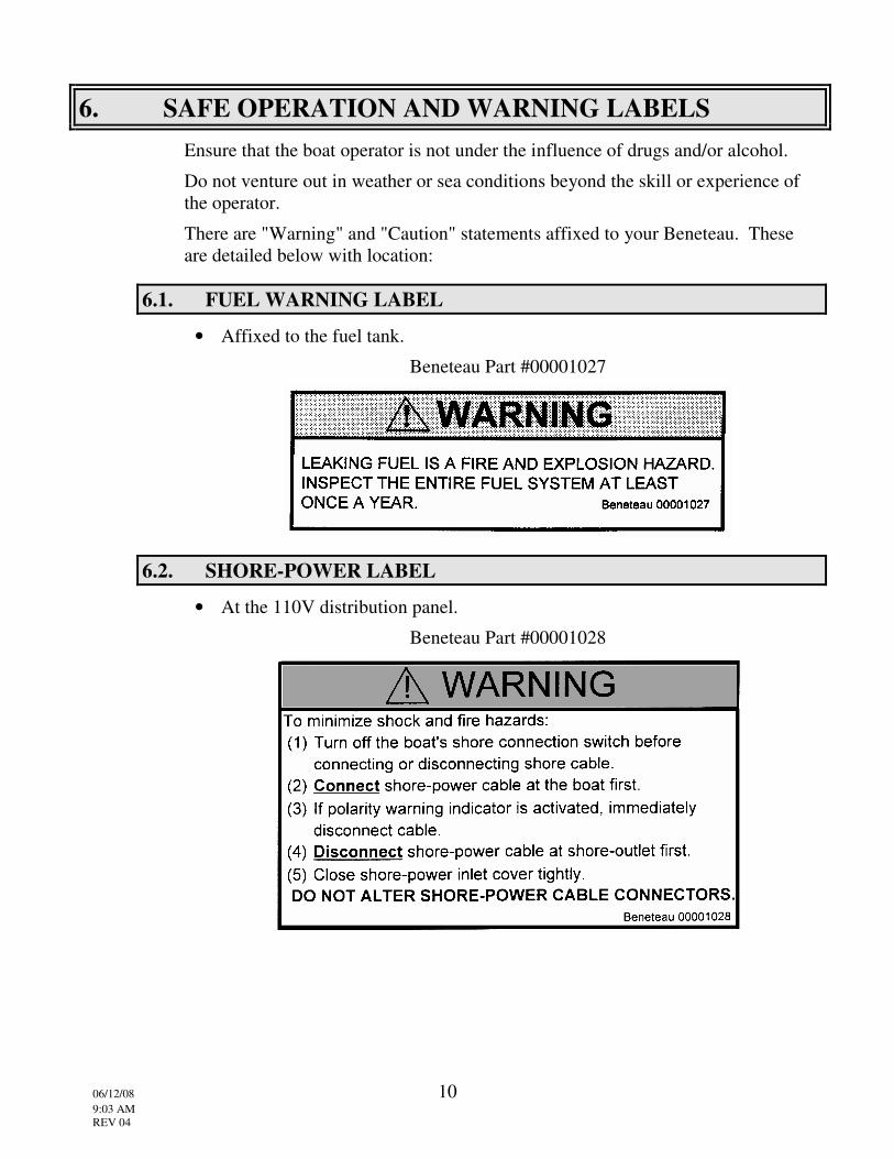
6.1. FUEL WARNING LABEL
• Affixed to the fuel tank.
Beneteau Part #00001027
6.2. SHORE-POWER LABEL
• At the 110V distribution panel.
Beneteau Part #00001028
06/12/08 11 9:03 AM REV 04
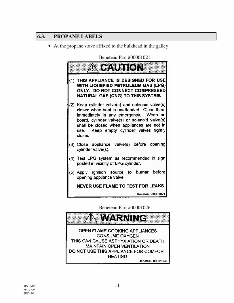
6.3. PROPANE LABELS
• At the propane stove affixed to the bulkhead in the galley
Beneteau Part #00001021
Beneteau Part #00001026
06/12/08 12 9:03 AM REV 04
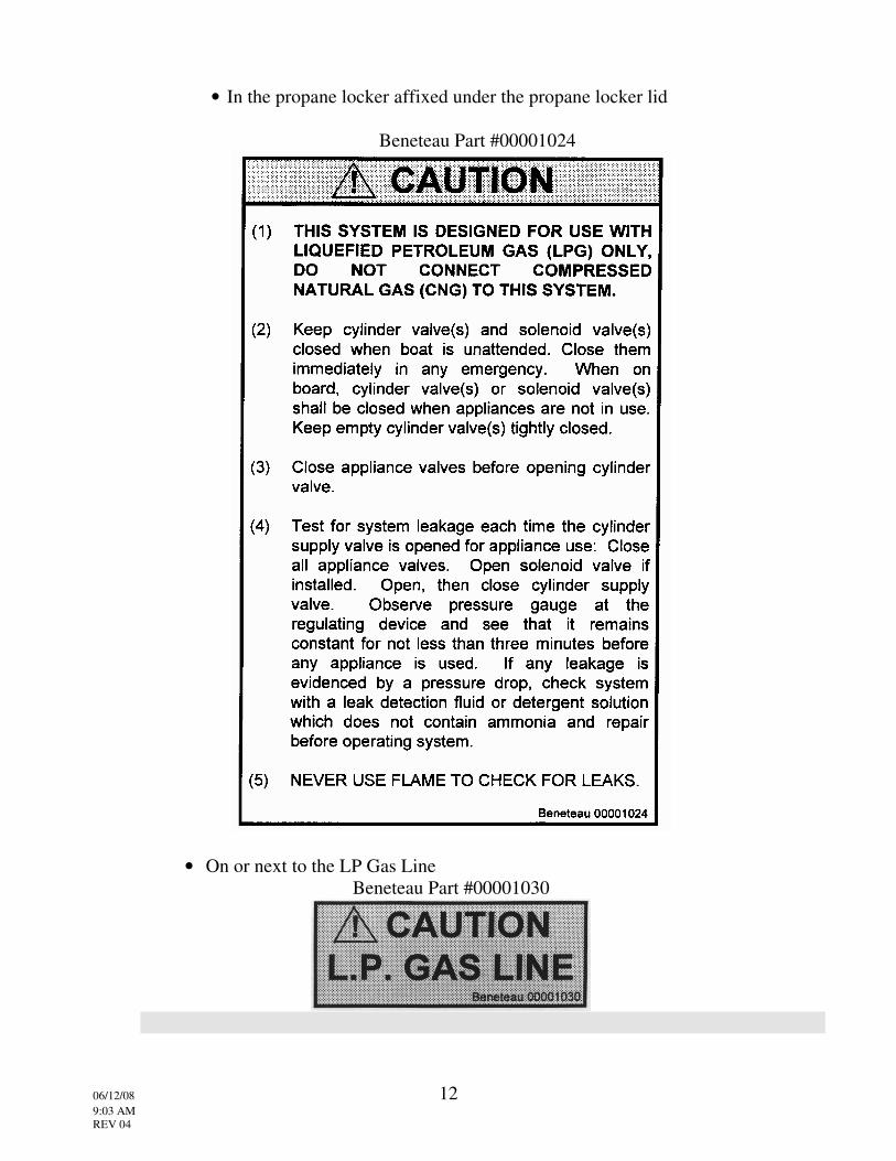
• In the propane locker affixed under the propane locker lid
Beneteau Part #00001024
• On or next to the LP Gas Line Beneteau Part #00001030
06/12/08 13 9:03 AM REV 04
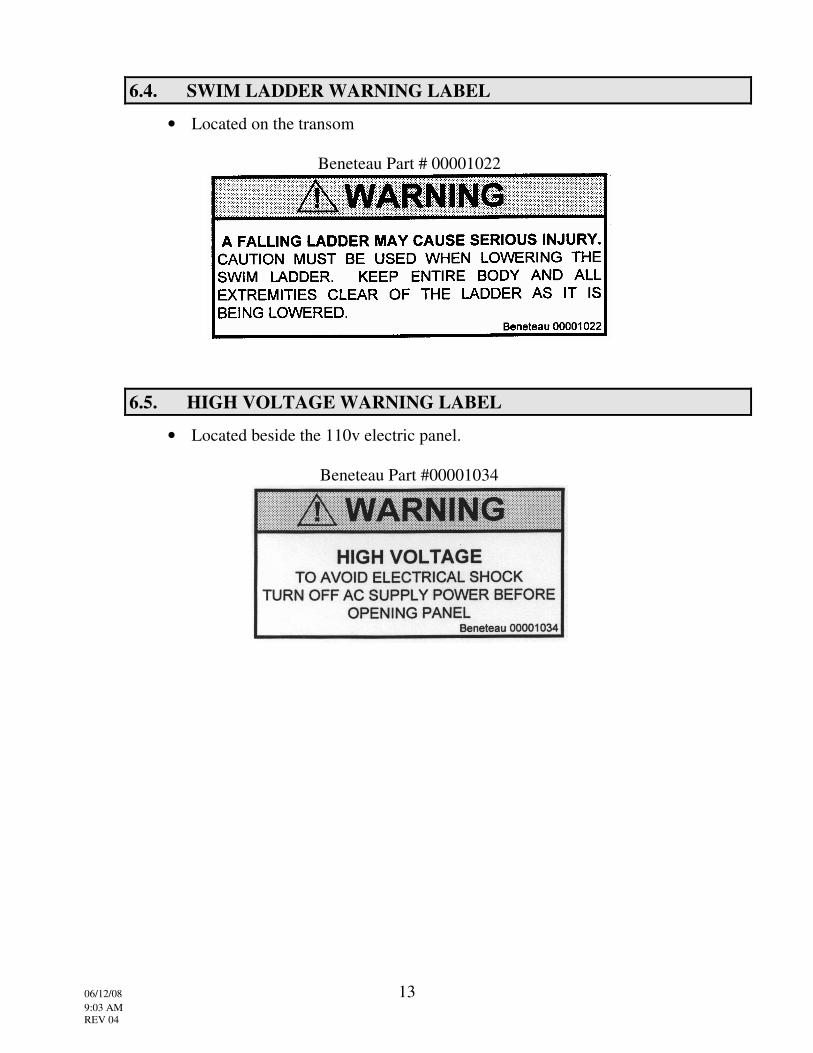
6.4. SWIM LADDER WARNING LABEL
• Located on the transom
Beneteau Part # 00001022
6.5. HIGH VOLTAGE WARNING LABEL
• Located beside the 110v electric panel.
Beneteau Part #00001034
06/12/08 14 9:05 AM Rev. 05
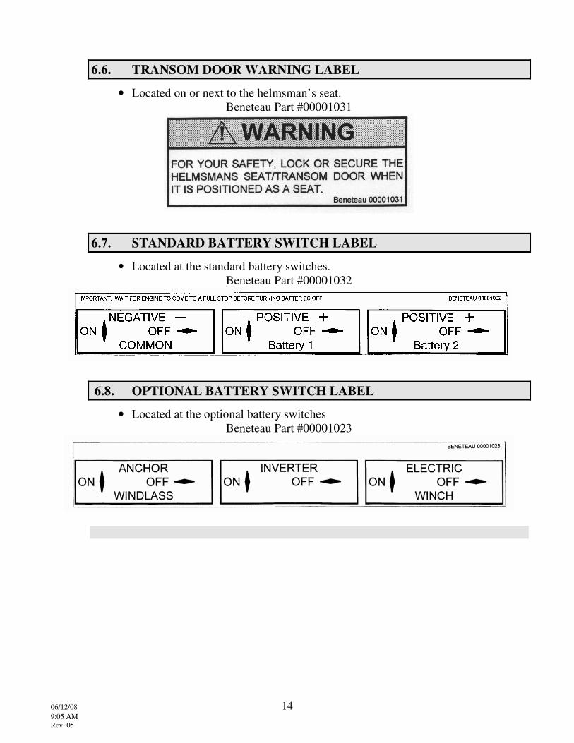
6.6. TRANSOM DOOR WARNING LABEL
• Located on or next to the helmsman’s seat. Beneteau Part #00001031
6.7. STANDARD BATTERY SWITCH LABEL
• Located at the standard battery switches. Beneteau Part #00001032
6.8. OPTIONAL BATTERY SWITCH LABEL
• Located at the optional battery switches Beneteau Part #00001023

06/12/08 15 9:05 AM Rev. 05
6.9. SLING LOCATION ARROWS LABEL
• Located at or near the hull to deck joint Beneteau Part #00001033
6.10. ANTI FREEZE CAUTION TAG
• Tied to the breaker for the water Beneteau Part #00001038
! CAUTION
BOAT SHIPPED FROM FACTORY WITH ANTIFREEZE IN WATER SYSTEM
CONSUMPTION OF ANTIFREEZE MAY CAUSE ILLNESS
SYSTEM MUST BE THOROUGHLY FLUSHED SEVERAL TIMES TO REMOVE ANTIFREEZE
BEFORE USE
Beneteau 00001038
06/12/08 16 9:05 AM Rev. 05
7. FEDERAL/STATE REGULATIONS
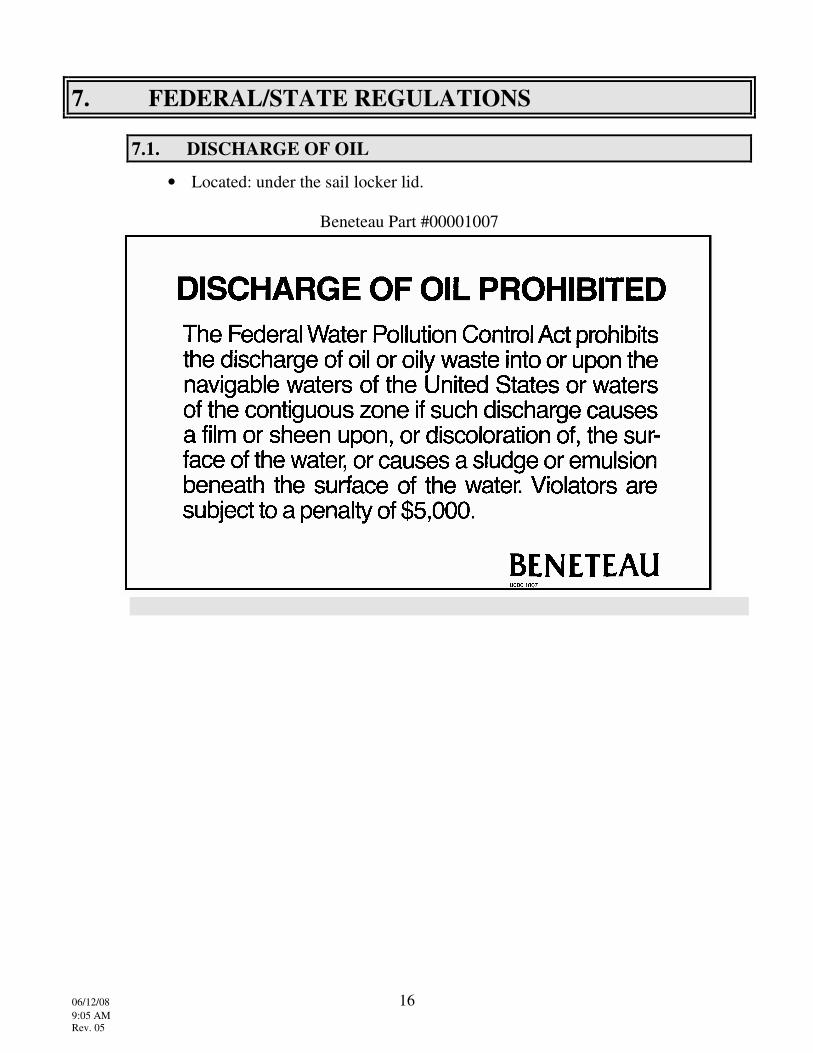
7.1. DISCHARGE OF OIL
• Located: under the sail locker lid.
Beneteau Part #00001007
06/12/08 17 9:05 AM Rev. 05
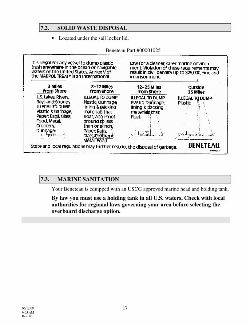
7.2. SOLID WASTE DISPOSAL
• Located under the sail locker lid.
Beneteau Part #00001025
7.3. MARINE SANITATION
Your Beneteau is equipped with an USCG approved marine head and holding tank.
By law you must use a holding tank in all U.S. waters, Check with local authorities for regional laws governing your area before selecting the overboard discharge option.
06/12/08 18 9:05 AM Rev. 05
8. ACCIDENT REPORTING
Knowledge of accident reporting requirements. Please refer to the following list for a copy of the U.S. Coast Guard Boating Accident form. For further information on where to obtain more forms, please call the U.S. Coast Guard Boating Safety Hotline at (800) 368-5647
NATIONAL VESSEL DOCUMENTATION CENTER 2039 STONEWALL JACKSON DR. FALLING WATERS, WV 25419 TOLL FREE: 1-800-799-8362 PHONE: (304) 271-2400 FAX: (304) 271-2405 CREDIT CARD FAX: (304) 271-2415

06/12/08 19 9:05 AM Rev. 05
9. RENDERING ASSISTANCE
United States Code, Title 46:
"The owner or operator of a vessel is required by law to render assistance to any individual or vessel in distress, so long as his vessel is not endangered in the process."
06/12/08 20 9:05 AM Rev. 05
10. COMMISSIONING
10.1. COMMISSIONING PROCEDURES
The first commissioning of a yacht is essentially the start of its life, and the importance of proper commissioning procedures at this time cannot be overstated. The commissioning procedure must be performed by Beneteau dealer personnel or those authorized by them. The owner also needs to concern himself with items such as safety equipment, which is considered to be his responsibility. See the Owner’s Operator’s Responsibilities section for details.
Complete lists of the pre-launch and post-launch checks employed during commissioning are provided in this section for those owners interested in understanding the decommissioning procedure, as well as for future use in any recommissionings that may be required after periods of wet or dry storage. The lists assume performance proffessionals and do not attempt to provide step-by-step instructions. Details of your yachts systems are available in section 13 of this manual and other manufacturers' instructions that are provided with the yacht.
The factory installed equipment, and items of responsibility that require attention by owner during commissioning are included in the list with the items marked with an asterisk (*), the owner installed equipment that require attention during commissioning are marked with a double asterisk (**).
10.2. * PRE-LAUNCH CHECKS
10.2.1. Hull Inspection • Check topsides, decks, and all interior spaces for cleanliness and proper finish.
Make certain that all foreign matter has been removed from the bilge areas, and check the following specific items:
• All thru-hull valves lubricated and closed, all hose clamps on all thu-hulls, shaft seals, bilge pumps, etc are tight.
• Propeller nut, retaining washer, and zinc properly installed and tightened.
• Shaft zinc installed if applicable.
• Steering gear and rudder operational and all bolts tight.
• Cutlass bearing in place and secured.
• Anti-fouling bottom paint applied.
06/12/08 21 9:05 AM Rev. 05
10.2.2. Machinery Inspection • Make an overall inspection of the machinery spaces. Ensure that they are free
of loose material that might interfere with machinery operation, and then check the following items:
• Engine oil, transmission fluid, and coolant levels satisfactory.
• All electrical switches OFF.
• Batteries fully charged, tied down, connected; electrolyte at proper level.
• Installation of all equipment completed.
• All fuel and propane valves CLOSED.
• Adequate amount of fuel in tank.
• Check to be sure that the shaft coupler is attached to the transmission.
• Check filters: Bilge, shower-sump, fresh water, and engine raw water.
10.2.3. Before Stepping Mast
WARNING! MOVE YOUR BOAT TO A POSITION THAT IS CLEAR OF OVERHEAD WIRES OR OBSTRUCTIONS. ELECTROCUTION MAY RESULT FROM CONTACT WITH ANY OVERHEAD WIRES!!
•••• * Check the following items:
• Shrouds, stays, spreaders, installed and properly secured to mast.
• Check standing rigging for kinks or defects.
• Masthead lights, spreader lights, and mast-mounted instrument units operational.
• VHF antenna installed. (If applicable)
• All chafe points on mast properly taped.
• If the mast is keel stepped: check that the mast has been choked correctly and that the mast boot has been installed and sealed.
10.2.4. Equipment On Board Check the following items:
•* Winch handles, emergency tiller, and bilge pump handles.
•** Anchor and ground tackle.
•** Dock lines and fenders.
•** Safety equipment:
1. Life preservers
2. Throwable horseshoe or ring buoy
06/12/08 22 9:05 AM Rev. 05
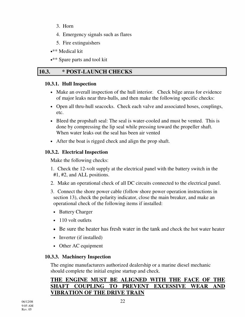
3. Horn
4. Emergency signals such as flares
5. Fire extinguishers
•** Medical kit
•** Spare parts and tool kit
10.3. * POST-LAUNCH CHECKS
10.3.1. Hull Inspection • Make an overall inspection of the hull interior. Check bilge areas for evidence
of major leaks near thru-hulls, and then make the following specific checks:
• Open all thru-hull seacocks. Check each valve and associated hoses, couplings, etc.
• Bleed the propshaft seal: The seal is water-cooled and must be vented. This is done by compressing the lip seal while pressing toward the propeller shaft. When water leaks out the seal has been air vented
• After the boat is rigged check and align the prop shaft.
10.3.2. Electrical Inspection Make the following checks:
1. Check the 12-volt supply at the electrical panel with the battery switch in the #1, #2, and ALL positions.
2. Make an operational check of all DC circuits connected to the electrical panel.
3. Connect the shore power cable (follow shore power operation instructions in section 13), check the polarity indicator, close the main breaker, and make an operational check of the following items if installed:
• Battery Charger
• 110 volt outlets
•••• Be sure the heater has fresh water in the tank and check the hot water heater • Inverter (if installed)
• Other AC equipment
10.3.3. Machinery Inspection The engine manufacturers authorized dealership or a marine diesel mechanic should complete the initial engine startup and check.
THE ENGINE MUST BE ALIGNED WITH THE FACE OF THE SHAFT COUPLING TO PREVENT EXCESSIVE WEAR AND VIBRATION OF THE DRIVE TRAIN
06/12/08 23 9:05 AM Rev. 05
The alignment must be checked again after the boat has been rigged and tuned. A marine mechanic should complete engine alignment. The basic procedure is to:
1. Loosen the transmission to shaft coupling bolts enough to slide a feeler gauge between the coupling plates.
2. Measure the gap all around the coupling to ensure the gap is constant.
3. If the gap varies, raise or lower the corners of the engine at the engine mounts until a constant gap is achieved.
4. Re tighten the coupling bolts
Secure the yacht to a pier or dock with bow, stern, and spring lines and operate the engine at low speeds in neutral, forward, and reverse. Check:
• Throttle and shift controls
• Engine operation
• Alternator output
• Water temperature (See engine owner's manual for operating temperature range).
• Oil pressure (See engine manual).
• Check the fuel system for leakage.
• Re-check the propshaft seal for proper adjustment. Adjust if necessary. (See propshaft seal manufactures instructions)
• Install and check the operation of the emergency tiller.
10.3.4. Rigging and Sails Check the following after mast is in place:
1. All standing rigging complete and in place, dockside tuning completed. (See section 13).
2. Mast boot installation completed.
3. All cotter pins in place and taped.
4. Running rigging in place.
5. Sails hoisted to check fit.
06/12/08 24 9:05 AM Rev. 05
10.3.5. Fresh Water System Check the following:
1. Water tanks full, no leaks at tank, fittings or vent hoses.
2. Pressure water system operational.
3. All faucets operational
4. Sinks and drains operational.
5. Hot water system operational.
6. All showers operational.
10.3.6. Head System Check the following:
1. Head, holding tank, or other Marine Sanitation Devices operational.
2. Head intake and discharge hoses for leaks, Y-valve and discharge plumbing.
10.3.7. Galley Check the following:
1. Check all propane pipes & hose fittings for leaks before lighting the stove.
DO NOT TEST FOR LEAKS WITH AN OPEN FLAME, WIPE EACH JOINT WITH A SOAPY SOLUTION AND LOOK FOR BUBBLES
2. Galley stove operational.
3. Galley sink drains correctly.
4. Ice box drains correctly.
5. Check all water hoses, valves, connectors and thru-hulls for leaks.
10.3.8. Bilge Check the electric and manual bilge pump for operation.
Check the electric bilge pump filter frequently for debris, the filter will fill rapidly during the initial period of sailing your new boat. Check the shower sump pumps and filters.
06/12/08 25 9:05 AM Rev. 05
11. MAINTENANCE OF YOUR BOAT
Your boat represents a sizable capital investment that needs special and regular care Safeguarding your investment and looking after your own safety should persuade you of the importance of careful and regular upkeep of your boat. The maintenance suggestions in the following sections will help you with the basics. Always refer to the original manufacturer's manual for specific guidelines on individual components.
NOTE: It is important to clean the bottom of your boat at least two or three times a year. General Hull Maintenance •••• DO NOT SAND THE HULL WITH COARSE SANDPAPER. •••• DO NOT USE SOLVENTS TO CLEAN HULL. •••• DO NOT WASH WITH PRESSURE MACHINE USING WATER
WARMER THAN 70 DEGREES F. (21 degrees C.). •••• DO NOT USE PRESSURE EXCESS OF 2175 LBS/SQ. FT. (150
BAR.) WHEN USING A HIGH PRESSURE SPRAY WASH. •••• DO NOT HOLD NOZZLE CLOSER THAN 4 INCHES (10 CM) TO
SURFACE OF HULL. •••• DO NOT MACHINE SAND. We believe the above points to be pertinent for all FRP boats.
11.1. GEL COAT
The gel-coat is vulnerable to any dents and scratches it may get during maneuvering in harbor and on a mooring. The best way to avoid them is to undertake maneuvering calmly, after thinking out all the relevant factors (such as speed, current, wind, and the layout of the harbor). Always have one of the crew ready to put out a fender at the right place. When bringing in the anchor chain, back off or swing the boat round so as not to rub the chain against the hull. Hold the anchor well clear as you bring it aboard so that it does not scrape the stem: lay it on deck and lash it down at once, if only temporarily.
Never use dirty fenders.
Hose off the hull and deck as often as possible, with fresh water.
Before hosing down, remember to check that the hatch covers are not in the ventilating position; and it is wise not to take on diesel oil or fresh water supplies while you are hosing off the hull.
06/12/08 26 9:05 AM Rev. 05
After a few years, the gel coat may be repolished, either with a lambs wool buffer and polish, or by hand using a polish or similar product. Your yard will also be able to supply you with special cleaning products for getting rid of stubborn stains.
11.2. MINOR GEL COAT REPAIRS
To fill in a scratch or small dent, order a Beneteau Gel coat Repair Kit with instructions for use, from your dealer or obtain a small quantity of gel coat and catalyst.
Clean the affected area and rub it down with wet-and-dry sandpaper, then dry it off thoroughly (use a hair-dryer if necessary). Mix the components of the gel coat, and fill the scratch using a spatula avoiding any excess; cover with a sheet of cellophane. Once hardened remove cellophane and rub down with very fine wet/dry sandpaper (grade 600 or 800), and finish off by polishing the new surface.
11.3. THE DECK AND DECK FITTINGS
Using a gentle liquid detergent, scrub all nonskid areas to keep them free of dirt.
Light-alloy sections (tracks, etc.) can be cleaned in the same manner.
The tiny spots of oxidation pitting that may appear on stainless steel parts are nothing to worry about. Polishing will remove them.
From time to time, lubricate pulley blocks and sheaves, turnbuckles, tracks and travelers with light grease or a water-repellent lubricant such as WD 40 or Triflow.
After a certain time at sea, your winches will need cleaning inside. They must be cleaned out completely once a year. Follow the manufacturer’s instructions carefully.
When dismantling deck fittings, have a bowl close at hand for putting the parts in, and circle the area with a rolled dishcloth, or the like, so that any screws or springs you drop do not roll overboard. Use the lubricant recommended by the manufacturer before reassembling.
Warning! Incorrect reassembly can cause accidents. Note the order in which parts are dismantled, which will make it easier to put them together again later.
Acrylic plastic hatch covers and portholes should be rinsed off with fresh water and rubbed over with a soft cloth soaked in liquid paraffin.
11.4. THE RUDDER
Once a year, check steering gear. If necessary renew any parts (bushings, glands, etc.) that are worn. Lubricate the steering chain and cable and or gears.
Never lubricate nylon, ertalon or teflon bushings, with either oil or grease, use only WD 40.
06/12/08 27 9:05 AM Rev. 05
If you have wheel steering, maintenance should be in accordance with the manufacturer's recommendations.
Make regular checks on all the clamps, the condition of the quadrant, the cables or push rods, guide sheaves and the chain in the column to the wheel.
Make regular checks of the steering end stops to ensure they are adequately stopping the rotation of the rudder, this is important for direct drive push rod systems. Over rotation of the rudder could cause a steering lock up.
11.5. INTERIOR WOOD
The internal woodwork used in most of our boats yacht's is varnished. This should be regularly rinsed off with fresh water and a little liquid detergent, then polished with a chamois leather.
Should the woodwork become damaged, gently rub it down with very fine sandpaper and touch it with several coats of the varnish. Your dealer will be able to order Beneteau varnish. When this is dry, rub it down with a very fine wet-and-dry sandpaper (grade 800 or 1000) and finish off with polish (or a silicone spray) or wax.
11.6. ELECTRICAL SYSTEMS
It is essential for an electrical system to have a battery in sound condition to function properly. The following are some of the things to maintain a battery in the best condition.
• Keep the battery clean and the terminal posts well greased.
• Keep the battery electrolyte checked regularly
• Keep the battery fully charged.
If you have to leave your boat unused for more than a month it is best to leave your batteries with your yard so that they can be kept charged. Keep a suitable charger onboard so you can recharge your batteries at dockside without having to turn on the engine.
If you have an inboard engine, check the condition and tension of the alternator drive belt. From time to time, spray a little WD 40 or something similar on all the connections to the control panel, terminal boxes and lamp sockets. Make sure that cable grommets are watertight; smear them with Vaseline so that they do not dry out and deteriorate.
11.6.1. Battery Maintenance Make sure that the level of the electrolyte is always at least 1/2" above the top of the plates. This level can change suddenly, due to evaporation in an overheated bilge.
06/12/08 28 9:05 AM Rev. 05
WARNING! THE ELECTROLYTE IN A BATTERY IS A SOLUTION OF SULFURIC ACID. IF ANY SHOULD ENTER THE EYES, RINSE IMMEDIATELY WITH LARGE AMOUNTS OF FRESH WATER, AND SEEK MEDICAL ATTENTION. ELECTROLYTE SPILLED ON SKIN SHOULD BE RINSED WELL WITH FRESH WATER. EVEN SMALL AMOUNTS OF ELECTROLYTE SPILLED ON CLOTHING WILL DESTROY THE CLOTHING.
If the level is low, fill the battery with distilled water and nothing else. The level of acidity (i.e. the relative density of the electrolyte) should also be checked from time to time.
CAUTION! USE ONLY PURE DISTILLED WATER TO REPLENISH ELECTROLYTE LEVELS. THE WATER FROM MANY CITY WATER SUPPLY SYSTEMS IS UNSATISFACTORY FOR BATTERY USE.
Keep battery connections clean and tight. A cup full of strong baking soda solution and a toothbrush will clean corrosion from the terminals and neutralize any spilled acid (do not allow any of the solution to enter the battery cells). A coating of petroleum jelly or silicone grease on the battery terminals will inhibit corrosion.
11.7. WATER SYSTEM
Check all joints regularly for leaks. Keep the tank(s) filled. If, however, you have to leave the boat unattended for several months, disconnect the water lines, purge them, and rinse them thoroughly with vinegar and water so that they do not form foul-smelling deposits.
Important: If the electric pump continues running when all the taps are closed, switch off the power supply at once and check the water system to find and overcome the leak that is causing this.
Check the thru-hulls, seacocks, connectors and hose clamps regularly. Make sure the seacocks turn freely.
11.8. MARINE HEAD
Maintenance consists of regularly pumping the system out with fresh water and leaving the holding tank empty whenever possible.
Check the thru-hulls, seacocks, connectors and hose clamps regularly. Make sure the seacocks turn freely.
06/12/08 29 9:05 AM Rev. 05
11.9. ENGINE
Whether maintenance of the power system is to be performed by the owner or delegated to a mechanic, it is the owner who must first initiate any action that is to take place. He must either perform the maintenance or decide to call someone to do the job. A working knowledge of the power system is essential in the first case, and preventive maintenance desirable in the second. The engine manual is, of course, the prime source for engine information and should be consulted, preferably before the fact. The following paragraphs are included as a supplement to cover any required maintenance procedures that are not a part of the engine manual.
We have already stressed the points that are of importance for an engine to keep working properly. It might be added that the engine compartment should be kept scrupulously clean; check for any unusual oil or fuel leaks. Inspect all the electrical connections frequently.
Drain the bowl of the fuel/water separator at regular intervals to lessen the chance of water damage to your engine’s fuel system. Keep fuel tanks filled.
Inspect the engine mounts and coupling for loose bolts regularly.
Check the alternator belt for the correct tension, keep a spare belt on hand.
Check all hoses and fuel lines for leaks regularly.
NOTE: Always have a spare set of sacrificial anodes on board, and regularly check those that are already fitted for deterioration; they should be replaced when their size has been reduced by half. The time this takes will vary with the waters in which the boat is used. Water temperature, salinity, the presence of neighboring boats, the nature of the bottom and the materials in the dock will all affect the life of your boat's anodes.
Order your spare anodes thru your dealer or from Beneteau Customer Service.
06/12/08 30 9:05 AM Rev. 05
CALIFORNIA
Proposition 65 Warning
Diesel engine exhaust and some of its constituents are
known to the State of California to cause cancer, birth
defects, and other reproductive harm.
11.10. SAILS
Check the sails regularly, as the slightest wear in the stitching or at a reinforced part can very quickly have dramatic consequences. Keep a small sail repair kit on board and a book showing how to carry out minor work yourself until you can get the job done by a professional sail maker.
Keep a special eye on points where the sails can chafe on the rigging or fittings - turnbuckles, lifelines, shrouds, spreaders, etc.
Salt water and sunshine take their toll on sails. Whenever possible, rinse the sails in fresh water and leave them stretched out (preferably on a lawn) to dry. Never dry a sail by hoisting it and letting it flog in the wind; this will very quickly cause the sail to deteriorate. Never fold and store a sail damp.
06/12/08 31 9:05 AM Rev. 05
12. WINTERIZING PROCEDURES
The end of the season is a good time for a complete inspection of all of the boat's systems. It is easy to take shortcuts when decommissioning your boat but proper lay-up procedures will ensure trouble free recommissioning in the spring.
The following sections are oriented towards hauling your boat for winter storage in a cold climate, but they are also a good guideline as a lay-up procedure for your Beneteau in any climate.
An improperly winterized boat will lead to costly repairs and extensive delays, we recommend winterization by a competent yard or your Beneteau Dealer. The owner must ensure that the boat is correctly winterized.
12.1. HAULING
Your Beneteau should be hauled for inspection and maintenance at least once a year; the frequency of haul-outs may vary due to your local conditions and marine growth. A good boatyard is seasoned in hauling and maneuvering boats on land, you may verify this by checking to see that the weight of the hull is resting firmly on the bottom of the keel and that even contact exists along the bottom of keel. Jack stands, or cradle uprights, are meant to balance the boat and not to support its weight.
12.2. BOTTOM
Clean the yacht's bottom of any growth as soon as the boat is hauled. It is generally preferred to wait until spring to paint the bottom. Use the following guidelines when using a pressure washer:
MAXIMUM WATER TEMPERATURE TO BE 70°°°° F. (21°°°° C.) MAXIMUM PRESSURE TO BE 2175 LBS./SQ. FT (150) BARS AT NO CLOSER THAN 4"
12.3. CUTLASS BEARING
The shaft strut contains a rubber type cutlass bearing. At haul out, be sure the bearing slots are clear and apply silicone lubricant or castor oil to the bearing to preserve its suppleness. Replace the cutlass bearing if excessive wear is evident. Be sure to realign the engine if the bearing is replaced. Bleed the propshaft seal after relaunching
12.4. ZINC
Replace the sacrificial zinc before relaunching the boat.
06/12/08 32 9:05 AM Rev. 05
12.5. FRESHWATER SYSTEM
This system is best winterized with one of the non-toxic antifreezes available for use in boat and recreational freshwater systems. It is an easy method, which replaces fresh water with a non-toxic antifreeze mixture.
Caution! Be sure to use correct non-toxic antifreeze.
1. Allow the hot heater water to cool, and open the pressure release valve on top. Disconnect the hot and cold water hoses and allow the tank to drain either in a bucket or into the bilge. Connect and clamp the hot and cold water hoses together using a short length of 1/2" pipe in order to bypass the heater.
2. Mix the appropriate amounts of antifreeze and water, as directed on the label, to deliver the degree of protection desired. Put 1-1/2 to 2 gallons of the solution into each water tank.
3. Open both tank selector valves on the manifold.
4. Turn on the pump and open all fixtures until antifreeze runs through. Be sure to open the hot water selector valve in order to supply antifreeze to the hot water hoses and through the bypass loop.
5. At this point, the freshwater system should be completely protected by antifreeze against freezing to a degree indicated by the strength of the solution placed into the supply tanks.
6. New boats delivered have their freshwater systems filled with antifreeze as described above, and are protected to -30 degrees F.
12.6. HEAD
Several days before completing haul-out procedures, fresh water should be allowed to stand in the head unit to dissolve any salt accumulation in the hoses and pump. Remove all water from the head. Special lubricants for the pump's internal mechanism are available. Check with your marine hardware dealer for a recommended brand. Never put oil, gas, kerosene, or alcohol in the head or they will ruin the internal valve.
Completely pump out all waste from the holding tank and pour in a cleansing, deodorizing solution. If possible, allow this to sit in the tank overnight, then completely pump out and drain the entire system. If antifreeze is used in the system, check in the manufacturer's literature for the recommended type.
12.7. ENGINE
Winterization by a marine mechanic is highly recommended to ensure that your engine is properly protected.
06/12/08 33 9:05 AM Rev. 05
Consult the Engine Owner's Manual for your specific engine's guidelines for winterizing. Follow the instructions carefully to ensure the engine is adequately protected.
The general procedure is to replace raw seawater with an antifreeze solution mixed to protect the engine in your local area and to check the heat exchanger side to ensure that it contains an adequate antifreeze solution as well.
1. Prior to hauling the boat, run the engine to achieve normal operating temperatures in order to open the thermostat.
2. Close the raw water intake thru hull and remove the hose from the valve hose barb.
3. Insert the intake hose in a bucket of antifreeze solution and run the engine briefly until all raw water is flushed thru the exhaust system and only the antifreeze solution is expelled from the exhaust.
4. Be sure the thru hull valve is opened after the boat is hauled.
12.8. FUEL SYSTEM
Consult your engine manual to clean any engine mounted fuel filters.
Drain any water from the bottom of the fuel/water separator.
The fuel tank should be kept full for winter storage with about 5% expansion room left at the top. Empty fuel tanks encourage the formation of condensation.
12.9. BATTERIES
Clean battery terminals and cable ends thoroughly of any corrosion with a baking soda and water solution, and apply a light protective layer of petroleum jelly.
Batteries should be fully charged before storage, and the fluid level maintained. Store batteries in a warm, dry place. Do not store batteries directly on a stone or cement floor.
12.10. SEACOCKS
Open and drain all seacocks after boat is hauled. Open all seacocks for winter storage.
12.11. BILGE
Completely pump out bilge of any water and clean out any debris present. Bilge pumps should be pumped dry and hoses disconnected, to ensure that no water is left in the system.
12.12. ICEBOX
06/12/08 34 9:05 AM Rev. 05
Remove any remaining food from the icebox and wash down thoroughly with warm water and detergent solution.
Odors can be removed with a baking soda and water solution, and an open box of baking soda left in the icebox will continue to remove odors throughout storage.
Completely pump out any water from the bottom of the icebox and make sure pump is completely dry of any water.
Leave icebox lid open during storage to allow ventilation.
12.13. STOVE
Depressurize the gas system and close all valves. Clean stove thoroughly. Remove fuel tanks and clean to remove any salt accumulation from their surface. Wipe down stove and tanks with a rag while applying a light layer of WD-40 or other lightweight, protective oil.
12.14. INTERIOR
Remove as much loose gear from the boat as possible and store in a clean dry place.
If cushions are left on board be sure they are dry and propped on edge to encourage ventilation.
Rinse and dry all floorboards and store them on their edge to encourage ventilation.
Leave all lockers clean and open for ventilation.
12.15. COVERING THE BOAT
Cover the boat adequately during storage to prevent excessive weathering.
BE SURE THE COVER DOES NOT CHAFE BOAT. Ventilation between the winter cover and the boat is required to avoid build up of humidity.
CAUTION! DO NOT USE BLACK POLYETHYLENE AND DO NOT SHRINK-WRAP THE BOAT BY TAPING TO THE HULL. ALWAYS ASSURE GOOD VENTILATION.
12.16. SAILS
Remove the sails, clean following the sail makers recommendations and store in a clean dry space.
12.17. MAST
The aluminum mast requires a minimum of care and maintenance. At the end of each season it should be washed with a mild detergent and water solution, followed
06/12/08 35 9:05 AM Rev. 05
by a complete rinsing with fresh water. Tie off all halyards and lifts, and inspect the mast completely for scratches, cracks or stress marks. Apply paint or a clear lacquer to any scratches found to prevent corrosion. Consult your dealer or a marine rigger if any cracking or stressing of the aluminum tube is found.
Check all hardware on mast carefully for signs of corrosion, and check the tightness of the fastenings. Masthead sheaves should show no signs of wear and should move freely. Lubricate if necessary.
12. SUPPLIER INFORMATION LIST
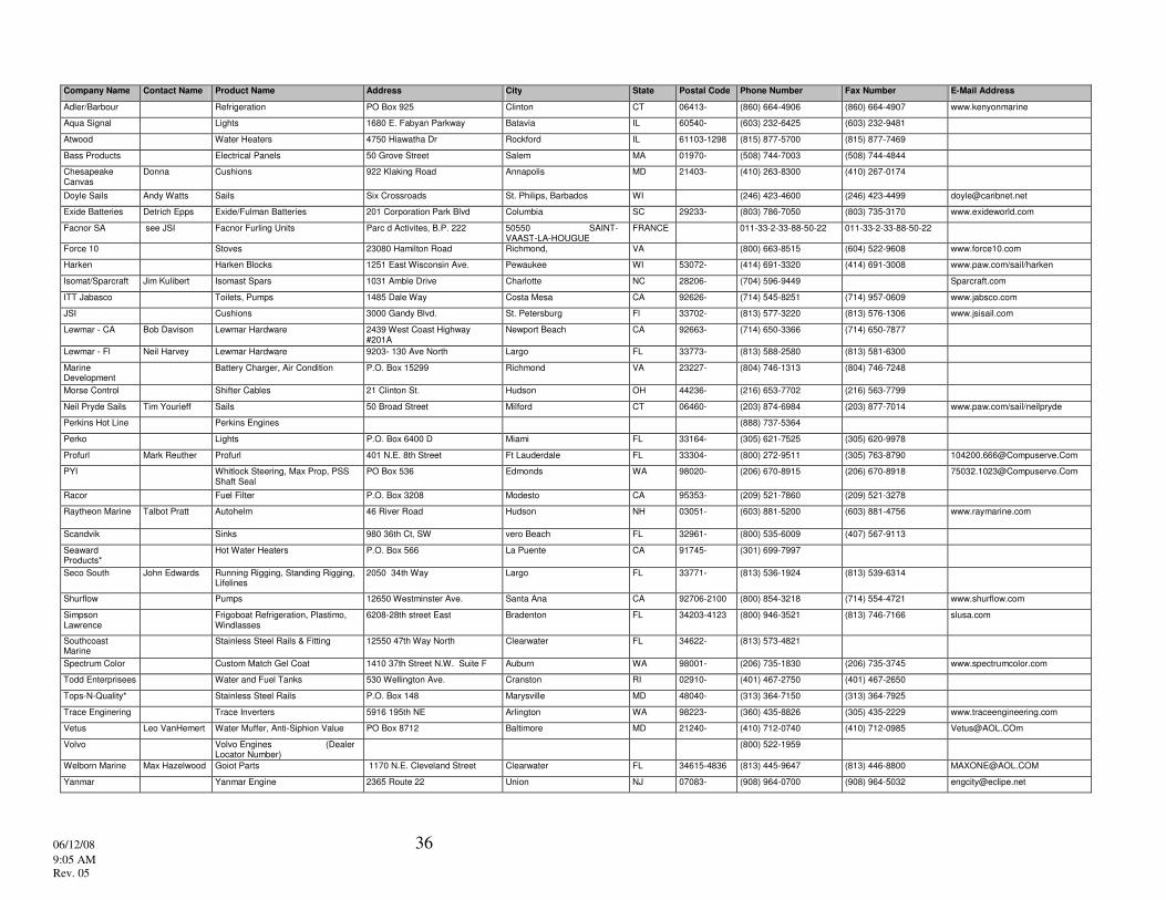
The following page lists our key suppliers in the United States. If you need information from a supplier not listed you may contact Beneteau’s Customer Service Department in Marion, South Carolina at 1-843-423-6459.
06/12/08 36 9:05 AM Rev. 05
Company Name Contact Name Product Name Address City State Postal Code Phone Number Fax Number E-Mail Address
Adler/Barbour Refrigeration PO Box 925 Clinton CT 06413- (860) 664-4906 (860) 664-4907 www.kenyonmarine
Aqua Signal Lights 1680 E. Fabyan Parkway Batavia IL 60540- (603) 232-6425 (603) 232-9481
Atwood Water Heaters 4750 Hiawatha Dr Rockford IL 61103-1298 (815) 877-5700 (815) 877-7469
Bass Products Electrical Panels 50 Grove Street Salem MA 01970- (508) 744-7003 (508) 744-4844
Chesapeake Canvas
Donna Cushions 922 Klaking Road Annapolis MD 21403- (410) 263-8300 (410) 267-0174
Doyle Sails Andy Watts Sails Six Crossroads St. Philips, Barbados WI (246) 423-4600 (246) 423-4499 [email protected]
Exide Batteries Detrich Epps Exide/Fulman Batteries 201 Corporation Park Blvd Columbia SC 29233- (803) 786-7050 (803) 735-3170 www.exideworld.com
Facnor SA see JSI Facnor Furling Units Parc d Activites, B.P. 222 50550 SAINT-VAAST-LA-HOUGUE
FRANCE 011-33-2-33-88-50-22 011-33-2-33-88-50-22
Force 10 Stoves 23080 Hamilton Road Richmond, VA (800) 663-8515 (604) 522-9608 www.force10.com
Harken Harken Blocks 1251 East Wisconsin Ave. Pewaukee WI 53072- (414) 691-3320 (414) 691-3008 www.paw.com/sail/harken
Isomat/Sparcraft Jim Kulibert Isomast Spars 1031 Amble Drive Charlotte NC 28206- (704) 596-9449 Sparcraft.com
ITT Jabasco Toilets, Pumps 1485 Dale Way Costa Mesa CA 92626- (714) 545-8251 (714) 957-0609 www.jabsco.com
JSI Cushions 3000 Gandy Blvd. St. Petersburg Fl 33702- (813) 577-3220 (813) 576-1306 www.jsisail.com
Lewmar - CA Bob Davison Lewmar Hardware 2439 West Coast Highway #201A
Newport Beach CA 92663- (714) 650-3366 (714) 650-7877
Lewmar - Fl Neil Harvey Lewmar Hardware 9203- 130 Ave North Largo FL 33773- (813) 588-2580 (813) 581-6300
Marine Development
Battery Charger, Air Condition P.O. Box 15299 Richmond VA 23227- (804) 746-1313 (804) 746-7248
Morse Control Shifter Cables 21 Clinton St. Hudson OH 44236- (216) 653-7702 (216) 563-7799
Neil Pryde Sails Tim Yourieff Sails 50 Broad Street Milford CT 06460- (203) 874-6984 (203) 877-7014 www.paw.com/sail/neilpryde
Perkins Hot Line Perkins Engines (888) 737-5364
Perko Lights P.O. Box 6400 D Miami FL 33164- (305) 621-7525 (305) 620-9978
Profurl Mark Reuther Profurl 401 N.E. 8th Street Ft Lauderdale FL 33304- (800) 272-9511 (305) 763-8790 [email protected]
PYI Whitlock Steering, Max Prop, PSS Shaft Seal
PO Box 536 Edmonds WA 98020- (206) 670-8915 (206) 670-8918 [email protected]
Racor Fuel Filter P.O. Box 3208 Modesto CA 95353- (209) 521-7860 (209) 521-3278
Raytheon Marine Talbot Pratt Autohelm 46 River Road Hudson NH 03051- (603) 881-5200 (603) 881-4756 www.raymarine.com
Scandvik Sinks 980 36th Ct, SW vero Beach FL 32961- (800) 535-6009 (407) 567-9113
Seaward Products*
Hot Water Heaters P.O. Box 566 La Puente CA 91745- (301) 699-7997
Seco South John Edwards Running Rigging, Standing Rigging, Lifelines
2050 34th Way Largo FL 33771- (813) 536-1924 (813) 539-6314
Shurflow Pumps 12650 Westminster Ave. Santa Ana CA 92706-2100 (800) 854-3218 (714) 554-4721 www.shurflow.com
Simpson Lawrence
Frigoboat Refrigeration, Plastimo, Windlasses
6208-28th street East Bradenton FL 34203-4123 (800) 946-3521 (813) 746-7166 slusa.com
Southcoast Marine
Stainless Steel Rails & Fitting 12550 47th Way North Clearwater FL 34622- (813) 573-4821
Spectrum Color Custom Match Gel Coat 1410 37th Street N.W. Suite F Auburn WA 98001- (206) 735-1830 (206) 735-3745 www.spectrumcolor.com
Todd Enterprisees Water and Fuel Tanks 530 Wellington Ave. Cranston RI 02910- (401) 467-2750 (401) 467-2650
Tops-N-Quality* Stainless Steel Rails P.O. Box 148 Marysville MD 48040- (313) 364-7150 (313) 364-7925
Trace Enginering Trace Inverters 5916 195th NE Arlington WA 98223- (360) 435-8826 (305) 435-2229 www.traceengineering.com
Vetus Leo VanHemert Water Muffer, Anti-Siphion Value PO Box 8712 Baltimore MD 21240- (410) 712-0740 (410) 712-0985 [email protected]
Volvo Volvo Engines (Dealer Locator Number)
(800) 522-1959
Welborn Marine Max Hazelwood Goiot Parts 1170 N.E. Cleveland Street Clearwater FL 34615-4836 (813) 445-9647 (813) 446-8800 [email protected]
Yanmar Yanmar Engine 2365 Route 22 Union NJ 07083- (908) 964-0700 (908) 964-5032 [email protected]
6/12/08 9:09 AM
Oceanis 381 Rev. 01
39
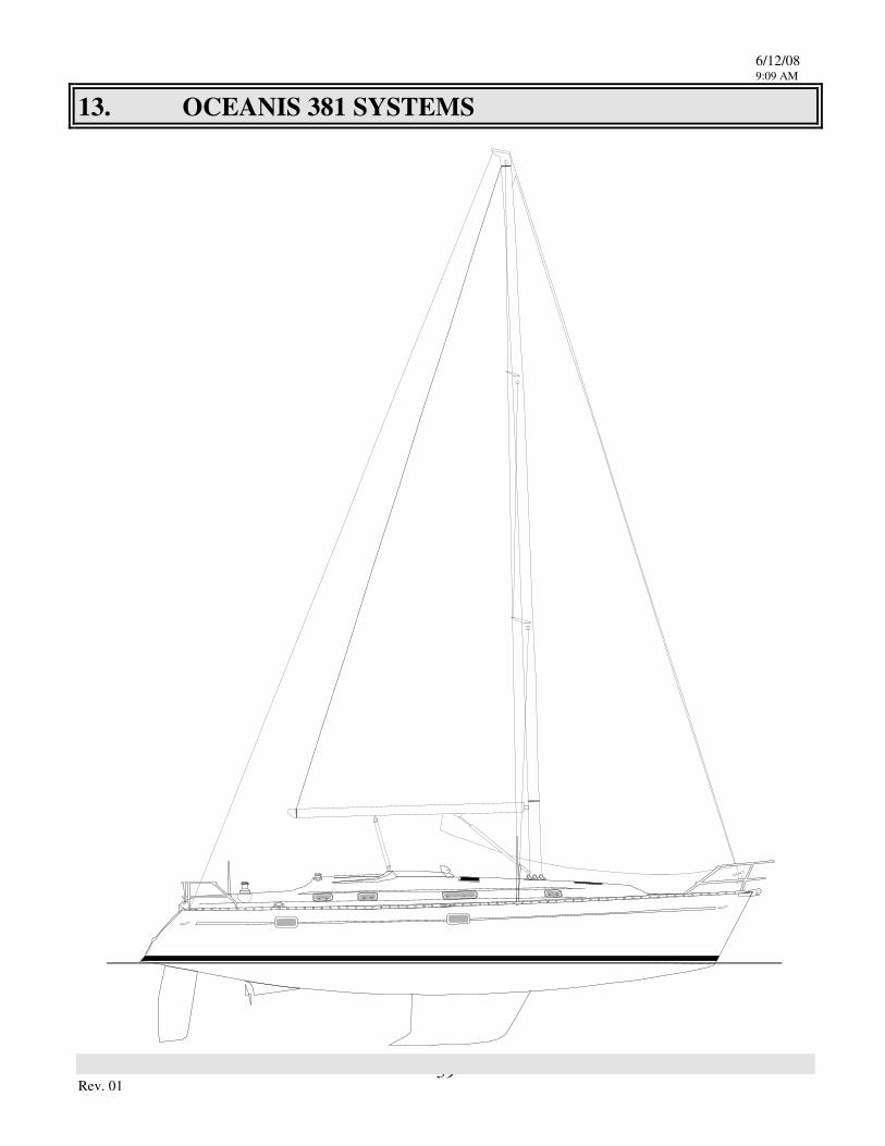
13. OCEANIS 381 SYSTEMS
6/12/08 9:09 AM
Oceanis 381 Rev. 01
40
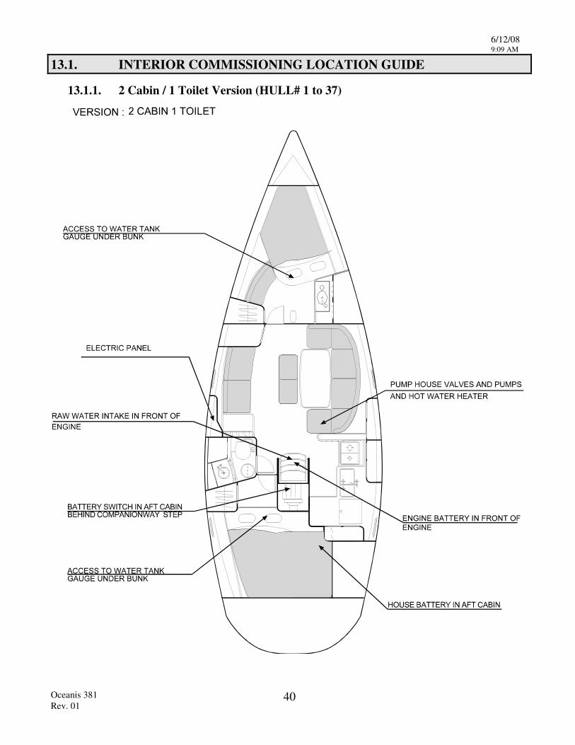
13.1. INTERIOR COMMISSIONING LOCATION GUIDE
13.1.1. 2 Cabin / 1 Toilet Version (HULL# 1 to 37)
6/12/08 9:09 AM
Oceanis 381 Rev. 01
41
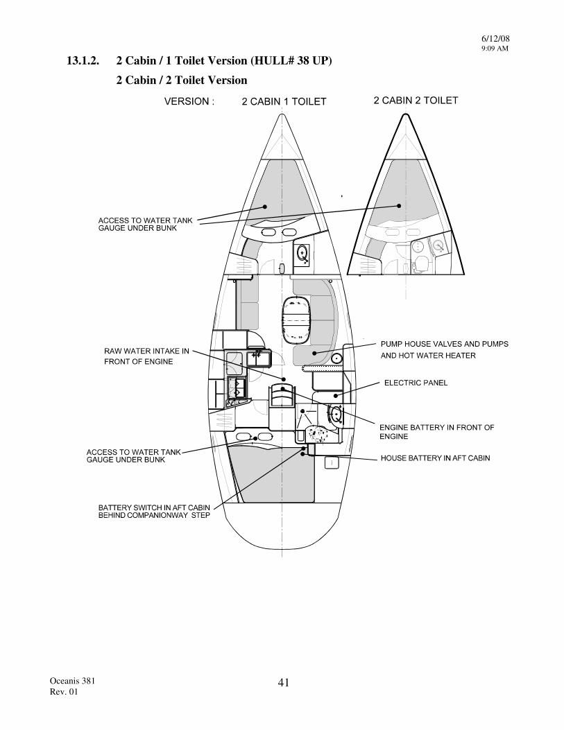
13.1.2. 2 Cabin / 1 Toilet Version (HULL# 38 UP)
2 Cabin / 2 Toilet Version
6/12/08 9:09 AM
Oceanis 381 Rev. 01
42
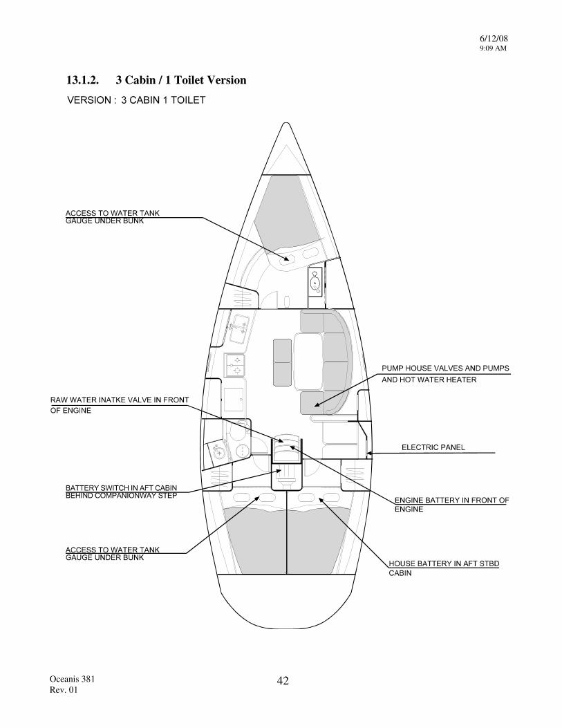
13.1.2. 3 Cabin / 1 Toilet Version
6/12/08 9:09 AM
Oceanis 381 Rev. 01
43
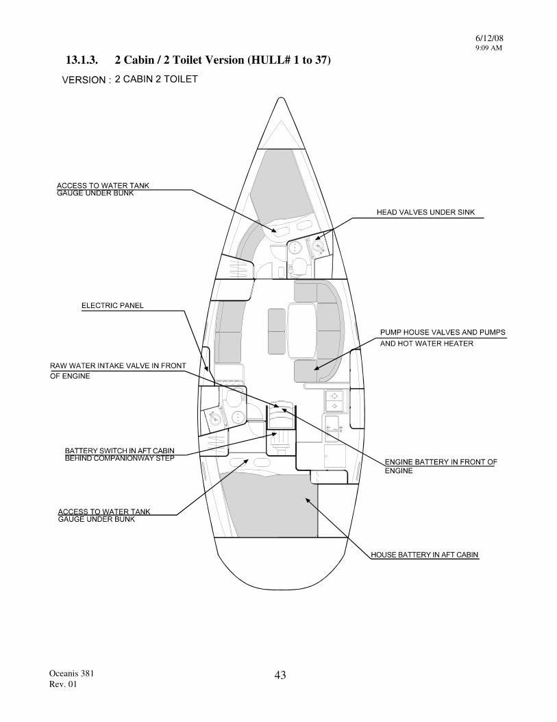
13.1.3. 2 Cabin / 2 Toilet Version (HULL# 1 to 37)
6/12/08 9:09 AM
Oceanis 381 Rev. 01
44
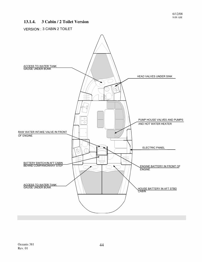
13.1.4. 3 Cabin / 2 Toilet Version
6/12/08 9:09 AM
Oceanis 381 Rev. 01
45
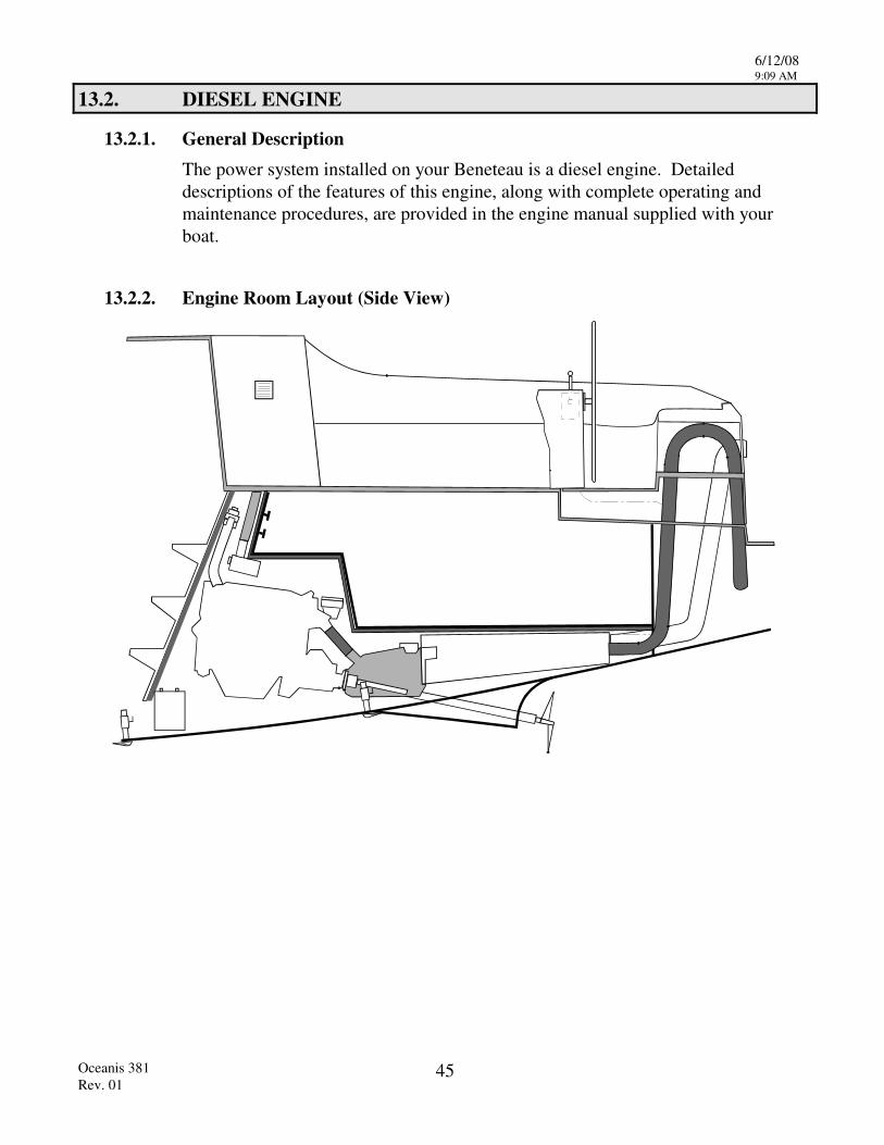
13.2. DIESEL ENGINE
13.2.1. General Description The power system installed on your Beneteau is a diesel engine. Detailed descriptions of the features of this engine, along with complete operating and maintenance procedures, are provided in the engine manual supplied with your boat.
13.2.2. Engine Room Layout (Side View)

6/12/08 9:09 AM
Oceanis 381 Rev. 01
46
13.2.3. Engine Room Layout (Top View)
13.2.4. Cutlass Bearing The cutlass bearing is a water lubricated rubber bearing that the prop shaft rotates in. It is critical for the shaft be perfectly aligned though the bearing and mated to the engine coupler to prevent premature wearing of the cutlass bearing.
6/12/08 9:09 AM
Oceanis 381 Rev. 01
47
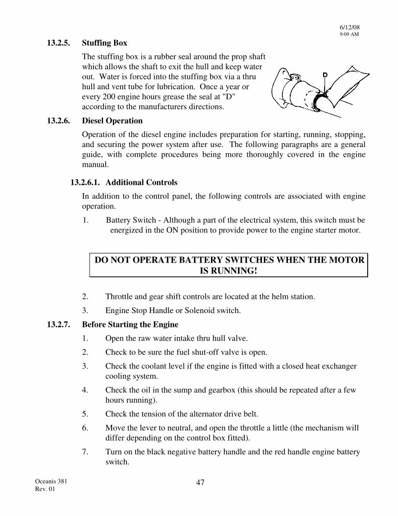
13.2.5. Stuffing Box The stuffing box is a rubber seal around the prop shaft which allows the shaft to exit the hull and keep water out. Water is forced into the stuffing box via a thru hull and vent tube for lubrication. Once a year or every 200 engine hours grease the seal at "D" according to the manufacturers directions.
13.2.6. Diesel Operation Operation of the diesel engine includes preparation for starting, running, stopping, and securing the power system after use. The following paragraphs are a general guide, with complete procedures being more thoroughly covered in the engine manual.
13.2.6.1. Additional Controls In addition to the control panel, the following controls are associated with engine operation.
1. Battery Switch - Although a part of the electrical system, this switch must be energized in the ON position to provide power to the engine starter motor.
DO NOT OPERATE BATTERY SWITCHES WHEN THE MOTOR IS RUNNING!
2. Throttle and gear shift controls are located at the helm station.
3. Engine Stop Handle or Solenoid switch.
13.2.7. Before Starting the Engine
1. Open the raw water intake thru hull valve.
2. Check to be sure the fuel shut-off valve is open.
3. Check the coolant level if the engine is fitted with a closed heat exchanger cooling system.
4. Check the oil in the sump and gearbox (this should be repeated after a few hours running).
5. Check the tension of the alternator drive belt.
6. Move the lever to neutral, and open the throttle a little (the mechanism will differ depending on the control box fitted).
7. Turn on the black negative battery handle and the red handle engine battery switch.
6/12/08 9:09 AM
Oceanis 381 Rev. 01
48
13.2.8. Starting the Engine Insert the ignition key and turn it to "ON" (and then to the intermediate preheat position if your boat's engine has this system). A warning alarm will sound as you start up - the engine manual explains the meaning of this alarm and its operation.
Press the starter button or turn the key, as appropriate, and release the button or key, as soon as the engine is running CHECK THE ENGINE EXHAUST FOR COOLING WATER DISCHARGE, IMMEDIATELY STOP THE ENGINE AND CHECK THE RAW WATER SYSTEM. IF NO COOLING WATER IS DISCHARGED FROM THE EXHAUST. Let the engine run for a moment, and then bring the throttle lever back to the idle position. After you engage the clutch, increase the engine speed very gradually (it should take at least five minutes to reach cruising speed), because a diesel engine will warm up only when it is under load.
Do not operate the starter for more than 10 seconds at a time. If the engine does not start, wait at least 30 seconds before trying again.
Once engine has started, check that the warning lights for oil and coolant pressure have gone out, and that the batteries are charging properly.
Check that the coolant water is circulating correctly, water should be either venting through the exhaust or passing through the heat-exchanger return circuit, depending on the cooling system fitted.
CAUTION! NEVER OPERATE THE BATTERY CIRCUIT SWITCH OR THE IGNITION KEY WHEN THE ENGINE IS RUNNING. THE RESULTING CURRENT SURGE WILL DAMAGE THE ALTERNATOR DIODES.
Engage the clutch firmly but not harshly. Do not rev the engine hard. When shifting from forward to reverse, or vice versa, the lever should be held in the neutral position for a moment before proceeding. Shifting should be performed with RPM reduced to idle. Keep a regular watch to make sure that the coolant water is circulating properly.
6/12/08 9:09 AM
Oceanis 381 Rev. 01
49
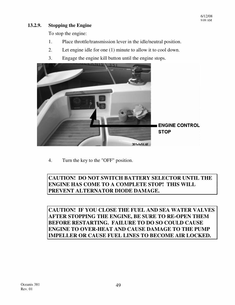
13.2.9. Stopping the Engine To stop the engine:
1. Place throttle/transmission lever in the idle/neutral position.
2. Let engine idle for one (1) minute to allow it to cool down.
3. Engage the engine kill button until the engine stops.
4. Turn the key to the "OFF" position.
CAUTION! DO NOT SWITCH BATTERY SELECTOR UNTIL THE ENGINE HAS COME TO A COMPLETE STOP! THIS WILL PREVENT ALTERNATOR DIODE DAMAGE.
CAUTION! IF YOU CLOSE THE FUEL AND SEA WATER VALVES AFTER STOPPING THE ENGINE, BE SURE TO RE-OPEN THEM BEFORE RESTARTING. FAILURE TO DO SO COULD CAUSE ENGINE TO OVER-HEAT AND CAUSE DAMAGE TO THE PUMP IMPELLER OR CAUSE FUEL LINES TO BECOME AIR LOCKED.
6/12/08 9:10 AM
Oceanis 381 Rev. 01
49
13.3. FUELING
While employment of a diesel engine results in a greatly reduced fire hazard when compared to gasoline, it should be remembered that diesel fuel is flammable, and that the employment of good fueling practices are necessary. The following steps are provided as guidelines.
13.3.1. Before Fueling 1. Extinguish all smoking materials and check the fueling area for other sources
of spark or flame. Remove if found.
2. Shut off the engine, and the electrical generator if one is aboard.
3. De-energize all electrical equipment.
4. Close all hatches and ports.
5. Ensure that a fire extinguisher is readily available.
6. Ensure that the proper (diesel, not gasoline) hose is about to be used.
WARNING! DO NOT FUEL DURING AN ELECTRICAL STORM. BESIDES THE OBVIOUS HAZARD OF LIGHTNING, THE POSSIBILITY OF STATIC DISCHARGE IS GREATLY INCREASED AT THE TIME.
6/12/08 9:10 AM
Oceanis 381 Rev. 01
50
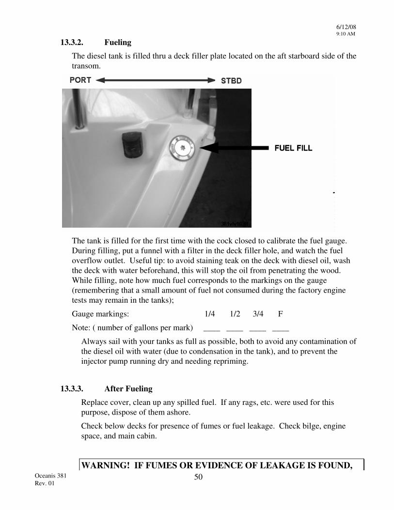
13.3.2. Fueling
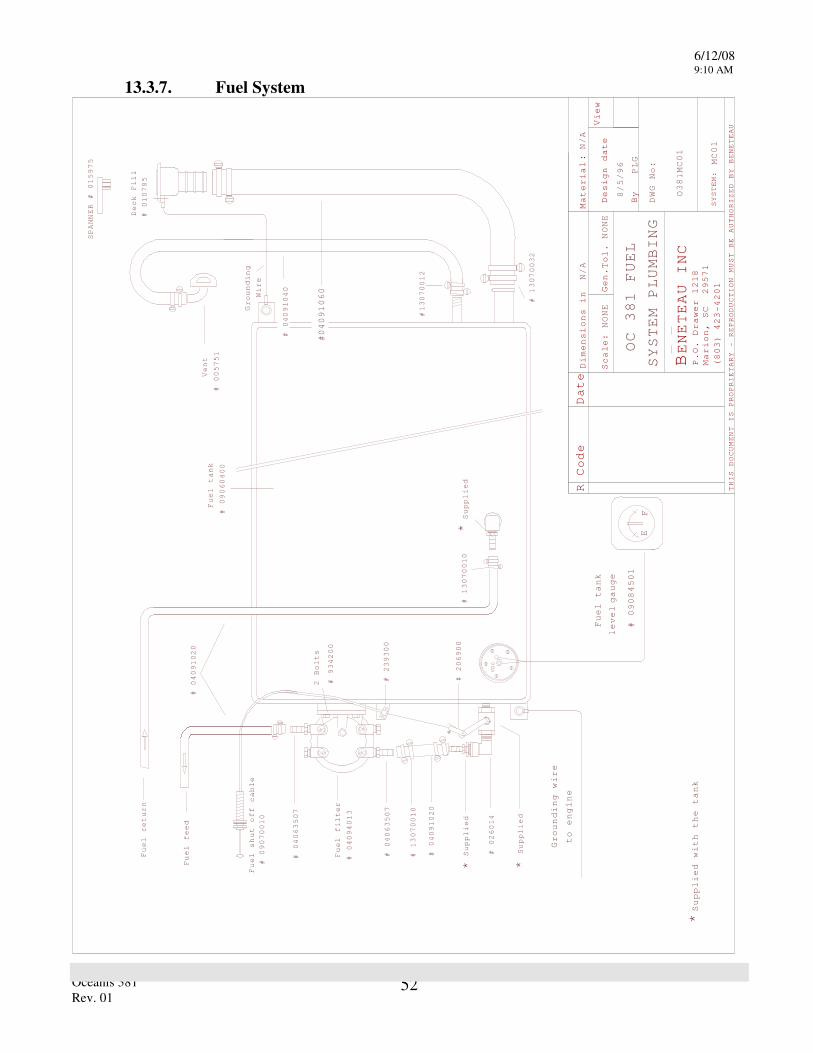
The diesel tank is filled thru a deck filler plate located on the aft starboard side of the transom.
The tank is filled for the first time with the cock closed to calibrate the fuel gauge. During filling, put a funnel with a filter in the deck filler hole, and watch the fuel overflow outlet. Useful tip: to avoid staining teak on the deck with diesel oil, wash the deck with water beforehand, this will stop the oil from penetrating the wood. While filling, note how much fuel corresponds to the markings on the gauge (remembering that a small amount of fuel not consumed during the factory engine tests may remain in the tanks);
Gauge markings: 1/4 1/2 3/4 F
Note: ( number of gallons per mark) ____ ____ ____ ____
Always sail with your tanks as full as possible, both to avoid any contamination of the diesel oil with water (due to condensation in the tank), and to prevent the injector pump running dry and needing repriming.
13.3.3. After Fueling
Replace cover, clean up any spilled fuel. If any rags, etc. were used for this purpose, dispose of them ashore.
Check below decks for presence of fumes or fuel leakage. Check bilge, engine space, and main cabin.
WARNING! IF FUMES OR EVIDENCE OF LEAKAGE IS FOUND,
6/12/08 9:10 AM
Oceanis 381 Rev. 01
51
DETERMINE THE CAUSE, CORRECT IT, AND CLEAN UP ANY SPILLAGE BEFORE PROCEEDING.
Open all hatches and ports to ventilate the boat.
Switch on battery.
The engine should be started only when it is certain that no potentially hazardous condition exists.
13.3.4. Fuel Sanitation
The fact that a diesel engine does not require an ignition system can, and usually does, result in an engine that is far superior to a gasoline engine with regard to dependability. Whether this is actually the case depends greatly on cleanliness of the fuel that is supplied to the engine since the close tolerances required by the engine's fuel delivery system make it extremely intolerant of any form of dirt or water contamination. The engine is supplied with filters that prevent contaminants from reaching the engine where they could cause damage, but a clogged filter, although providing this protection, can also stop an engine. Keeping the filters free of dirt and water is an obvious answer to this problem, and the cleaning schedules set forth in the engine manual will in most cases keep filters clean enough to prevent stoppage.
13.3.5. Bacterial Contamination
A factor that can cause additional problems is bacterial contamination of the diesel fuel. The bacteria involved need both water and fuel to exist, and if present, will thrive in a fuel tank. As they multiply, they form a filter-choking brown slime. Often their presence will not be known until rough weather churns up the fuel tank causing clogged filters at a most inopportune time. Keeping water out of the fuel will, of course, prevent the problem entirely, and while every effort should be made towards this, such as obtaining fuel from reputable dealers, it must be remembered that a certain amount of water due to normal condensation in the tank is to be expected.
13.3.6. Fuel Additives Fuel additives or conditioners provide means of combating this problem. These additives break the water down to a molecular level, dispersing it throughout the fuel and allowing it to pass harmlessly through the fuel system. Various brands of this product are available at marine supply stores. As with all products of this nature, the directions on the container should be carefully followed.
6/12/08 9:10 AM
Oceanis 381 Rev. 01
52
13.3.7. Fuel System
Fuel filter
#
Fuel shut off cable
# 09070010
# # # 026014
# 130700
# 04091020
Supplied
Supplied
# 09060400
Vent
# 04091040
# 010785
# 13070032
VDO
#
# 239300
* *
Supplied
*
2 Bolts
# 934200
Grounding
Wire
Deck Fill
13070012
#
#04091060
04094013
04063507
10
206900
04063507
Fuel tank
Fuel return
Fuel feed
# 005751
SPANNER # 015975
* Su
pplied with the tank
# 09084501
FE
Fuel tank
gauge
level
Grounding wire
to engine
# 13070010
#
04091020
R Code Date
Material
Scale:
Gen.
Design date
By
View
THIS DOCUMENT IS PROPRIETARY - REPRODUCTION
MUST BE AUTHORIZED BY BENETEAU
BENETEAU INC
P.O. Drawer 1218
Marion, SC 29571
(803) 423-4201
:
Dimensions in
Tol.
NONE
NONE
N/A
DWG No:
SYSTEM:
N/A
PLG
PLUMBING
SYSTEM
OC 381 FUEL
8/5/96
O381MC01
MC01
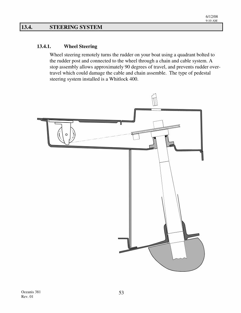
6/12/08 9:10 AM
Oceanis 381 Rev. 01
53
13.4. STEERING SYSTEM
13.4.1. Wheel Steering Wheel steering remotely turns the rudder on your boat using a quadrant bolted to the rudder post and connected to the wheel through a chain and cable system. A stop assembly allows approximately 90 degrees of travel, and prevents rudder over-travel which could damage the cable and chain assemble. The type of pedestal steering system installed is a Whitlock 400.
6/12/08 9:10 AM
Oceanis 381 Rev. 01
54
13.4.2. Wheel Steering Operation
Wheel steering requires use in order to obtain familiarity with it. A feel for your boat will develop and a sensitivity to conditions will increase your control.
NOTE: When backing under auxiliary power in reverse gear, it is necessary to maintain a hold on the steering wheel the entire time. The rudder and steering wheel have a tendency to rotate with force if left unattended while backing. This is due to the normally large area aft of the rudder post becoming the forward area, thus creating an imbalance.
The rudder stop system is designed to produce a positive stop to prevent over-turning the mechanisms of the steering system. It is not designed to absorb the potentially tremendous load of a rudder turning freely while backing. INSPECT the rudder stops on a regular basis to ensure they limit rudder travel to the correct amount, failure to limit rudder play may result in steering failure!
CAUTION! ALLOWING THE RUDDER AND WHEEL TO SPIN OUT OF CONTROL WHEN BACKING MAY CAUSE SERIOUS DAMAGE TO THE STEERING SYSTEM, POSSIBLY RESULTING IN A DANGEROUS LOSS OF STEERING CONTROL.
When leaving the boat at a mooring or slip, make sure the wheel brake is properly tightened. Do not allow the system to free wheel as excessive wear or damage may result.
13.4.3. Emergency Tiller As a safety precaution on your Beneteau, an emergency tiller has been provided as a backup to the wheel steering system. Remove the deck plate with a winch handle and slip emergency tiller into top of rudder post.
NOTE: PRACTICE USING THE EMERGENCY TILLER AND BE SURE ALL CREW MEMBERS KNOW THE LOCATION AND OPERATION OF THE EMERGENCY TILLER.
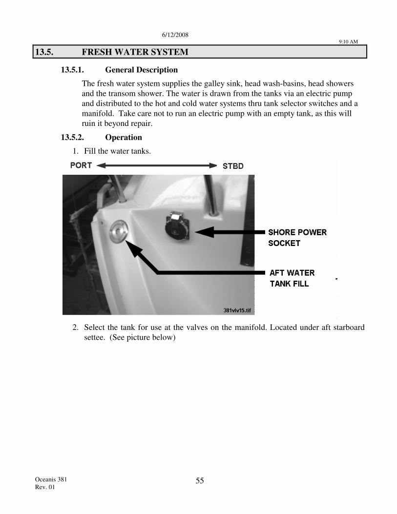
6/12/2008
9:10 AM
Oceanis 381 Rev. 01
55
13.5. FRESH WATER SYSTEM
13.5.1. General Description
The fresh water system supplies the galley sink, head wash-basins, head showers and the transom shower. The water is drawn from the tanks via an electric pump and distributed to the hot and cold water systems thru tank selector switches and a manifold. Take care not to run an electric pump with an empty tank, as this will ruin it beyond repair.
13.5.2. Operation
1. Fill the water tanks.
2. Select the tank for use at the valves on the manifold. Located under aft starboard
settee. (See picture below)
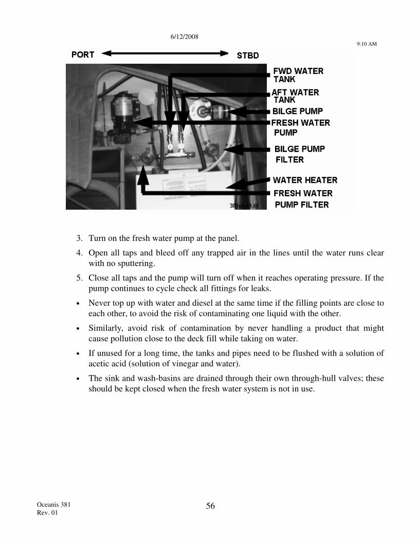
6/12/2008
9:10 AM
Oceanis 381 Rev. 01
56
3. Turn on the fresh water pump at the panel.
4. Open all taps and bleed off any trapped air in the lines until the water runs clear with no sputtering.
5. Close all taps and the pump will turn off when it reaches operating pressure. If the pump continues to cycle check all fittings for leaks.
• Never top up with water and diesel at the same time if the filling points are close to each other, to avoid the risk of contaminating one liquid with the other.
• Similarly, avoid risk of contamination by never handling a product that might cause pollution close to the deck fill while taking on water.
• If unused for a long time, the tanks and pipes need to be flushed with a solution of acetic acid (solution of vinegar and water).
• The sink and wash-basins are drained through their own through-hull valves; these should be kept closed when the fresh water system is not in use.
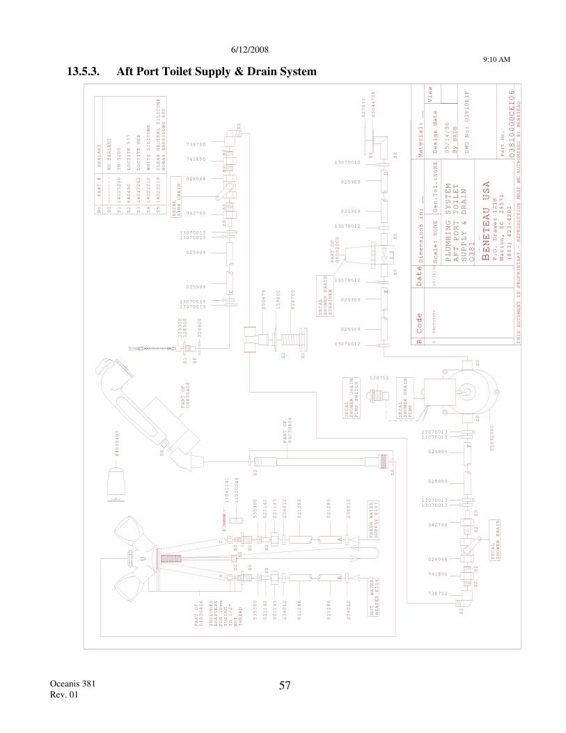
6/12/2008
9:10 AM
Oceanis 381 Rev. 01
57
13.5.3. Aft Port Toilet Supply & Drain System
R Code Date
Mater
Scale
Design date
By
View
THIS DOCUMENT IS PROPRIETARY - REPRODUCTION
MUST BE AUTHORIZED BY BENETEAU
BENETEAU USA
P.O. Drawer 1218
Marion, SC 29571
(803) 423-4201
Part No.
:
PROTOTYPE
0
NONE
Dimensions in:
__
ial:
Gen.Tol.:NONE
__
BADB
PLUMBING SYSTEM
DWG No:
AFT
TOILET
SUPPLY & DRAIN
PART #
No
S0
SEALANT
S1
3M 5200
S2
LOCTITE 577
S3
LOCTITE RED
S5
CLEAR NEUTRAL SILICONE
MOBAY BAYSILONE 400
14025200
642450
14017262
14022210
--------
NO SEALANT
WATER
EI0
EI0
S0
S2
236012
02128
02128
236012
236012
02128
02128
236012
S0
S0
535300
021141
021145
021145
021141
535300
S0
S0
S0
S0
S0
PART OF
PART OF
PART OF
HOT
4FRESH WATER 3
6 655
04030406
04030406
0403040
HC
HEATER
SUPPLY
S0
6
BA
S0
S0DECAL
S0
S0
DECAL
STRAINER
SHOWER DRAIN
PUMP
SHOWER DRAIN
S0
S2
13070011307001
13070011307001
342700
13070012
13070012
PART OF
05092000
13070011307001
05092000
13070011307001
13070012
13070012
C
DE
F
025909
025909
025909
025909
025909
025909
025909
025909
33
33
33
33
13061141
11000046
INCLUDES
ADAPTERS
FOR 10mm
TUBING
TO 1/2"
NPT
THREAD
04030407
DECAL
SHOWER DRAIN
PUMP SWITCH
530752
S2
S1
S2
824700
159000
000679
DECAL
SINK DRAIN
026068
741800
738700
S2
S2
S2
S2
S2
S0
S2
342700
026068
741800
738700
DECAL
SHOWER DRAIN
/96
/96
PORT
O1
O0EIF
O10000CEI06
S0
05/14
05/14
38
38
03044705
027611
S4
14022212
WHITE SILICONE
S4
S1
S0
128500
129300
324600
381
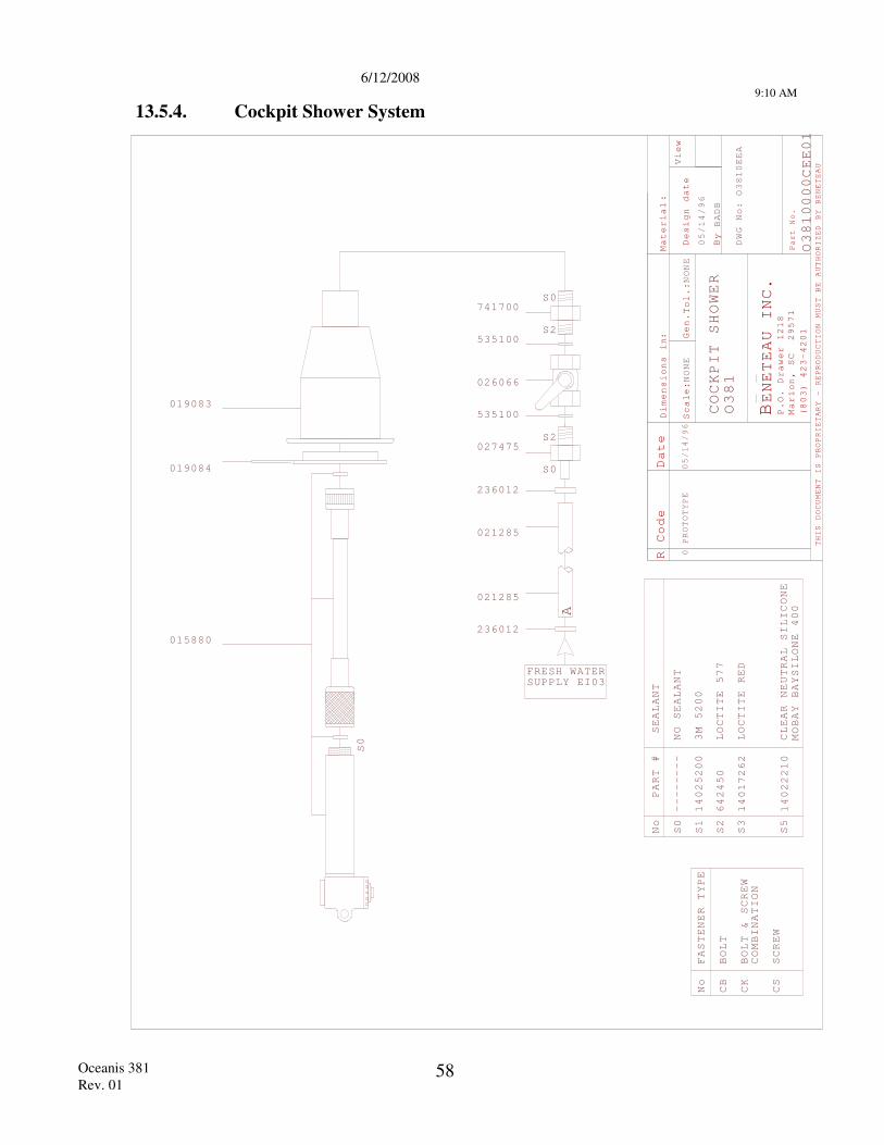
6/12/2008
9:10 AM
Oceanis 381 Rev. 01
58
13.5.4. Cockpit Shower System
R Code
Material
Scale
Gen.
Design date
By
View
THIS DOCUMENT IS PROPRIETARY - REPRODUCTION
MUST BE AUTHORIZED BY BENETEAU
BENETEAU INC
P.O. Drawer 1218
Marion, SC 29571
(803) 423-4201
Part No.
Dimensions i
:n
.
Date
:
:
NONE
Tol.:
NONE
BADB
PROTOTYPE
0
COCKPIT SHOWER
DWG No:
PART #
No
S0
SEALANT
S1
3M 5200
S2
LOCTITE 577
S3
LOCTITE RED
S5
CLEAR NEUTRAL SILICONE
MOBAY BAYSILONE 400
14025200
642450
14017262
14022210
--------
NO SEALANT
No
CB
BOLT
FASTENER TYPE
CK
BOLT & SCREW
COMBINATION
CS
SCREW
S0
S0
S2
S2
S0
236012
021285
021285
236012
027475
535100
026066
535100
741700
019083
019084
015880
A
EE01
/96
/96
1
10000C10EEA
FRESH WATERSUPPLY EI03
05/14
05/14
O38
O38
O38
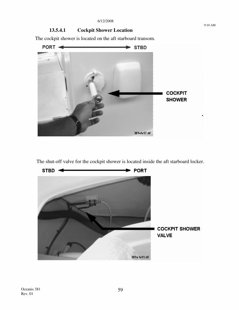
6/12/2008
9:10 AM
Oceanis 381 Rev. 01
59
13.5.4.1 Cockpit Shower Location The cockpit shower is located on the aft starboard transom.
The shut-off valve for the cockpit shower is located inside the aft starboard locker.
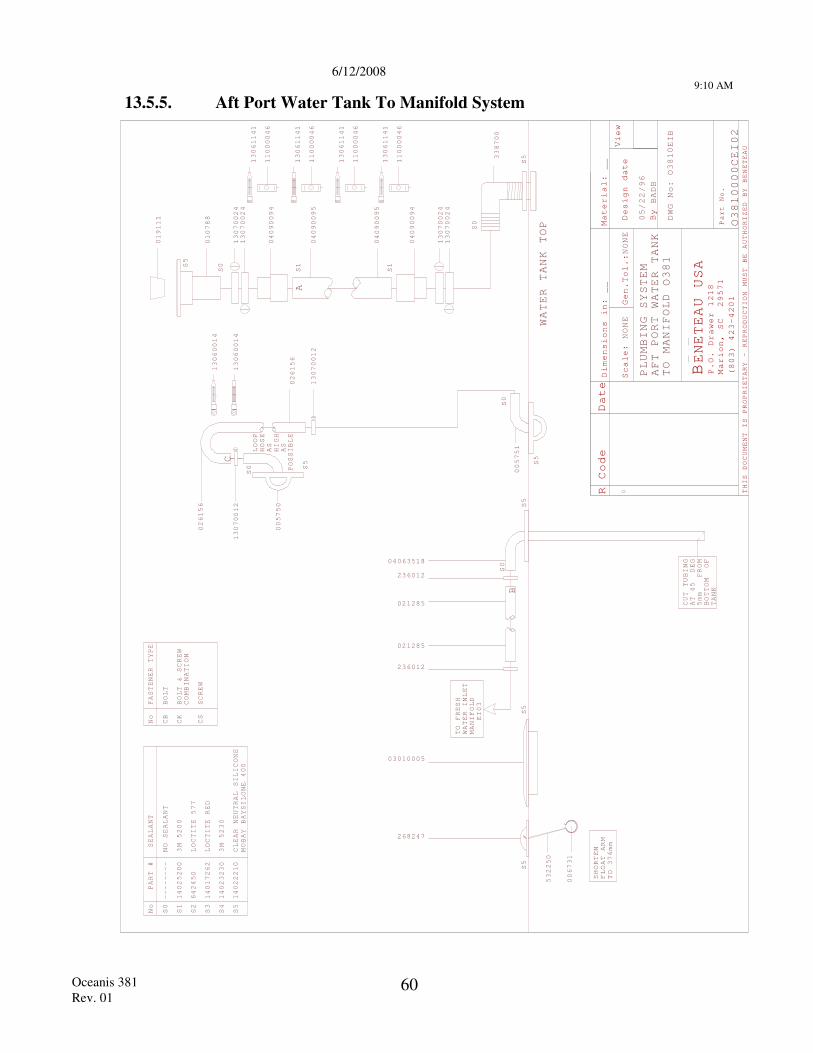
6/12/2008
9:10 AM
Oceanis 381 Rev. 01
60
13.5.5. Aft Port Water Tank To Manifold System
R Code Date
Mater
Scale
Design date
By
View
THIS DOCUMENT IS PROPRIETARY - REPRODUCTION
MUST BE AUTHORIZED BY BENETEAU
BENETEAU USA
P.O. Drawer 1218
Marion, SC 29571
(803) 423-4201
Part No.
:
0
NONE
Dimensions in:
__
ial:
Gen.Tol.:NONE
__
BADB
PLUMBING SYSTEM
DWG No:
WATER TANK
TO MANIFOLD
PORT
S1
S1
S0
LOOP
HOSE
AS
HIGH
AS
POSSIBLE
S5
CUT TUBING
AT 45
5mm
BOTTOM DEG
FROM
OF
MANIFOLD
PART #
No
S0
SEALANT
--------
NO SEALANT
No
CB
BOLT
FASTENER TYPE
S1
3M 5200
S2
LOCTITE 577
S3
LOCTITE RED
S4
3M 5230
S5
CLEAR NEUTRAL SILICONE
MOBAY BAYSILONE 400
14025200
642450
14017262
14023230
14022210
CK
BOLT & SCREW
COMBINATION
CS
SCREW
TANK
EI03
TO FRESH
WATER INLET
WATER TANK
TOP
S5
S5
S5
S5
S0
019111
010788
13070024
13070024
04090094
04090095
04090095
04090094
13070024
13070024
13070012
005750
13070012
04063518
236012
021285
021285
236012
268247
532250
006731
A
C
B
03010005
13061141
11000046
13061141
11000046
13061141
11000046
13061141
11000046
13060014
13060014
O3810EIB
AFT
O381
05/22/96
O3810000CEI02
S0
S
338700
5
S5
S0
005751
026156
026156
SHORTEN
FLOAT ARM
TO 376mm
S0
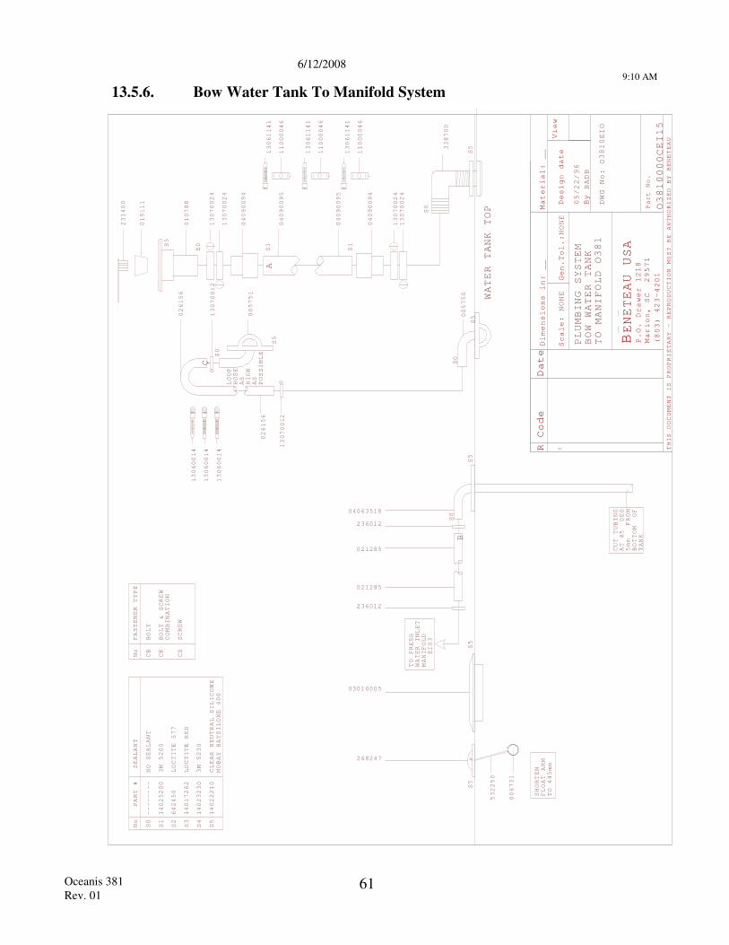
6/12/2008
9:10 AM
Oceanis 381 Rev. 01
61
13.5.6. Bow Water Tank To Manifold System
R Code Date
Mater
Scale
Design date
By
View
THIS DOCUMENT IS PROPRIETARY - REPRODUCTION
MUST BE AUTHORIZED BY BENETEAU
BENETEAU USA
P.O. Drawer 1218
Marion, SC 29571
(803) 423-4201
Part No.
:0
NONE
Dimensions in:
__
ial:
Gen.Tol.:NONE
__
BADB
PLUMBING SYSTEM
DWG No:
S1
S1
S0S5
CUT TUBING
AT 45
5mm
BOTTOM DEG
FROM
OF
MANIFOLD
PART #
No
S0
SEALANT
--------
NO SEALANT
No
CB
BOLT
FASTENER TYPE
S1
3M 5200
S2
LOCTITE 577
S3
LOCTITE RED
S4
3M 5230
S5
CLEAR NEUTRAL SILICONE
MOBAY BAYSILONE 400
14025200
642450
14017262
14023230
14022210
CK
BOLT & SCREW
COMBINATION
CS
SCREW
TANK
EI03
TO FRESH
WATER INLET
WATER TANK
TOP
S5
S5
S5
LOOP
HOSE
AS
HIGH
AS
POSSIBLE
S5
S0
231400
019111
010788
13070024
13070024
04090094
04090095
13070012
005751
13070012
04090095
04090094
13070024
13070024
04063518
236012
021285
021285
236012
268247
532250
006731
B
A
C
TO MANIFOLD
03010005
13061141
11000046
13061141
11000046
13061141
11000046
13060014
13060014
13060014
05/22/96
BOW WATER TANK
O381
O3810EIO
O3810000CEI15
S0
S
338700
5005750
S5
S0
S0
026156
026156
SHORTEN
FLOAT ARM
TO
mm
445
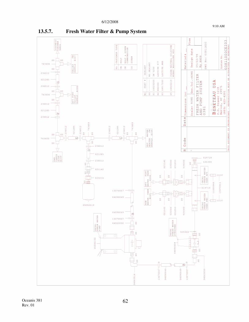
6/12/2008
9:10 AM
Oceanis 381 Rev. 01
62
13.5.7. Fresh Water Filter & Pump System
R Code Date
Scale
Gen.
Design date
By
View
THIS DOCUMENT IS PROPRIETARY - REPRODUCTION
MUST BE AUTHORIZED BY BENETEAU
BENETEAU USA
P.O. Drawer 1218
Marion, SC 29571
(803) 423-4201
D:
:0
imensions in:
__
NONE
Tol.:NONE
Material: __
BADB
DWG No:
System No.
FRESH WATER FILTER
AND PUMP SYSTEM
CEI03
O381
O381
EIC
O381
000
05/22/96
13070007
13070007
04090049
04090049
A
DECAL
FRESH WATER
PUMP
05090150
S0
S0
S0
04063514
S0
B
04063050
13070007
04090049
04090049
13070007
S2
S2
S0
236012
236012
021285
021142
023216
S0
S0
S0
743600
05092019
236012
236012
021285
S0S0
S0
021285
236012
236012
S0S0
S0
743600
021285
236012
236012
S0S0
S0
743600
743600
SUPPLY
TOILET
E
PART #
No
S0
SEALANT
S1
3M 5200
S2
LOCTITE 577
S3
LOCTITE RED
S5
CLEAR NEUTRAL SILICONE
MOBAY BAYSILONE 400
14025200
642450
14017262
14022210
--------
NO SEALANT
No
CB
BOLT
FASTENER TYPE
CK
BOLT & SCREW
COMBINATION
CS
SCREW
S0
S0
S0
743600
SUPPLY
EI
HOT
WATER
HEATER FW
04
236012
236012
021285
FWD
CABIN
SINK
EI09
COCKPI
SHOWER
E01
T
GALLEY FW
SUPPLY EI07
AFT
PORT
EI06
S0
S0
S0
S0
S0
S0
S0
13070011
11000046
WATER TANK
EI
WATER TANK
EI
021142
535300
031053
535300
021142
535300
031053
535300
AFT
PORT
02
BOW
15
019719
DECAL
FRESH WATER
TANK FWD
DECAL
FRESH WATER
TANK AFT
019718
535300
S0
S0
DECAL
FRESH WATER
STRAINER
04094004
535300
S0
04063050
C
D
E
FG
1
1
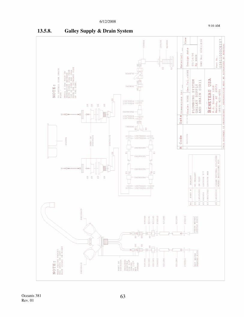
6/12/2008
9:10 AM
Oceanis 381 Rev. 01
63
13.5.8. Galley Supply & Drain System
R Code Date
Mater
Scale
Design date
By
View
THIS DOCUMENT IS PROPRIETARY - REPRODUCTION
MUST BE AUTHORIZED BY BENETEAU
BENETEAU USA
P.O. Drawer 1218
Marion, SC 29571
(803) 423-4201
Part No.
:
PROTOTYPE
0
NONE
Dimensions in:
__
ial:
Gen.Tol.:NONE
__
BADB
PLUMBING SYSTEM
DWG No:
PART #
No
S0
SEALANT
S1
3M 5200
S2
LOCTITE 577
S3
LOCTITE RED
S5
CLEAR NEUTRAL SILICONE
MOBAY BAYSILONE 400
14025200
642450
14017262
14022210
--------
NO SEALANT
GALLEY SUPPLY
AND DRAIN
236012
02128
02128
236012
236012
02128
02128
236012
S0
S0
021145
021141
535300
021145
021141
535300
S0
S0
S0
S0
PART OF
04030405
HC
FRESH WATER
SUPPLY EI03
HOT WATER
HEATER EI04
665 5
NOTE:
WHEN
FACING FAUCET
RED (HOT) ON LEFT
BLUE (COLD) ON RIGHT
AB
000CEI07
04030409
04030410
INCLUDES
ADAPTER
FOR 3/8"
TUBING
TO 1/2"
NPT
THREAD
/96
/96
OEIG
O
O1
S0
S0
S0
PART OF
04030101
04030102
S0
S0
S0
S0
S2
S1
S2
824
00
159
9
738900
100
S2
746000
1307002413070024
04090092
1307002413070024
342800
026070
DRILL A 6mm HOLE ON
SEPERATION BETWEEN
BOTH SINKS 20mm FROM
TOP OF SINK
NOTE:
TO INSTALL SINK DRAIN
PLUG -
AND 20mm
FROM THE OUTBOARD SIDE
OF THE SINK.
1307002413070024
04090094
04090095
04090095
04090094
1307002413070024
S0
S0
S0
S0
S1
S1
S1
S1
S0
S0
S1
1
1
1
1
C D
05/14
38
381
38
05/14
032981
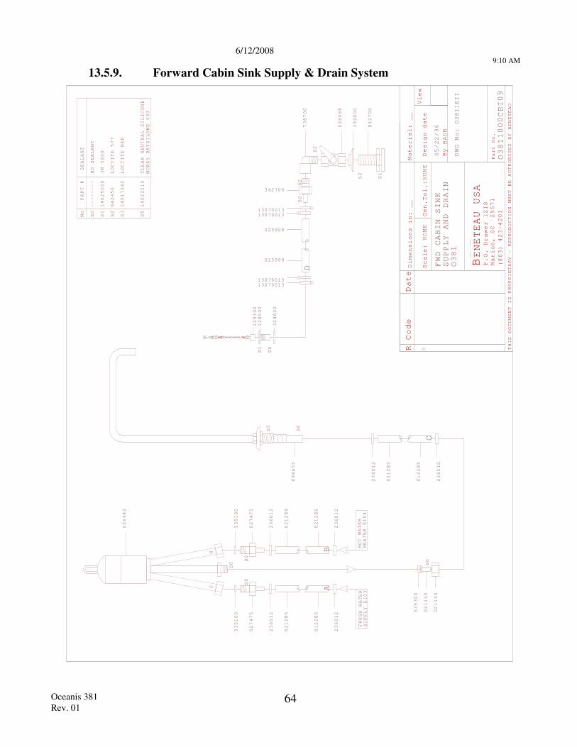
6/12/2008
9:10 AM
Oceanis 381 Rev. 01
64
13.5.9. Forward Cabin Sink Supply & Drain System
R Code Date
Mater
Scale
Design date
By
View
THIS DOCUMENT IS PROPRIETARY - REPRODUCTION
MUST BE AUTHORIZED BY BENETEAU
BENETEAU USA
P.O. Drawer 1218
Marion, SC 29571
(803) 423-4201
Part No.
:0
NONE
Dimensions in:
__
ial:
Gen.Tol.:NONE
__
BADB
DWG No:
FRESH WATER
SUPPLY EI03
HOT WATER
HEATER EI04
CH
S0
S0
S0
FWD CABIN SINK
SUPPLY AND DRAIN
O381
O3811000CEI09
O3811EII
05/22/96
535100
027475
236012
021285
012285
236012
535100
027475
236012
021286
021286
236012
026942
AB
S0
S1
S2
S2
S2
025909
025909
1307001313070013
1307001313070013
342700
738700
026068
159000
842700
S1
S0
128500
129300
324600
PART #
No
S0
SEALANT
S1
3M 5200
S2
LOCTITE 577
S3
LOCTITE RED
S5
CLEAR NEUTRAL SILICONE
MOBAY BAYSILONE 400
14025200
642450
14017262
14022210
--------
NO SEALANT
S0
535300
02114
02114
236012
021285
012285
236012
C
D
096655
S0
S5
0 4
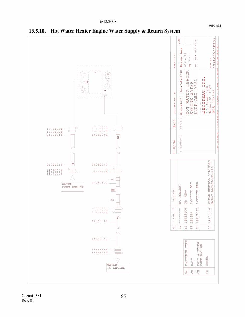
6/12/2008
9:10 AM
Oceanis 381 Rev. 01
65
13.5.10. Hot Water Heater Engine Water Supply & Return System
R Code
Material
Scale
Gen.
Design date
By
View
THIS DOCUMENT IS PROPRIETARY - REPRODUCTION
MUST BE AUTHORIZED BY BENETEAU
BENETEAU INC
P.O. Drawer 1218
Marion, SC 29571
(803) 423-4201
Part No.
Dimensions i
:n
.
Date
:
:
NONE
Tol.:
NONE
BADB
PROTOTYPE
0
DWG No:
HOT WATER HEATER
PART #
No
S0
SEALANT
S1
3M 5200
S2
LOCTITE 577
S3
LOCTITE RED
S5
CLEAR NEUTRAL SILICONE
MOBAY BAYSILONE 400
14025200
642450
14017262
14022210
--------
NO SEALANT
No
CB
BOLT
FASTENER TYPE
CK
BOLT & SCREW
COMBINATION
CS
SCREW
ENGINE WATER
SUPP+RET
WATERTO ENGINE
S0
S0
1307000813070008
1307000813070008
04067100
1307000813070008
04090040
04090040
1307000813070008
1307000813070008
1307000813070008
FROM ENGINEWATER
C
H
C
0000CEI05
110EIE
1
/96
/96
B
A04090040
04090040
04090040
04090040
05/14
05/14
O38
O38
O38
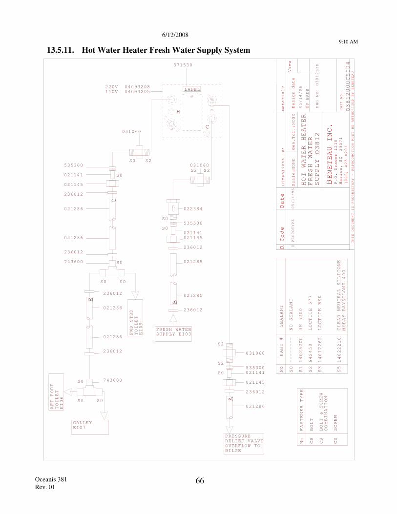
6/12/2008
9:10 AM
Oceanis 381 Rev. 01
66
13.5.11. Hot Water Heater Fresh Water Supply System
R Code
Material
Scale
Gen.
Design date
By
View
THIS DOCUMENT IS PROPRIETARY - REPRODUCTION
MUST BE AUTHORIZED BY BENETEAU
BENETEAU INC
P.O. Drawer 1218
Marion, SC 29571
(803) 423-4201
Part No.
Dimensions i
:n
.
Date
:
:
NONE
Tol.:
NONE
BADB
PROTOTYPE
0
DWG No:
HOT WATER HEATER
FRESH WATER
SUPPLY
PART #
No
S0
SEALANT
S1
3M 5200
S2
LOCTITE 577
S3
LOCTITE RED
S5
CLEAR NEUTRAL SILICONE
MOBAY BAYSILONE 400
14025200
642450
14017262
14022210
--------
NO SEALANT
No
CB
BOLT
FASTENER TYPE
CK
BOLT & SCREW
COMBINATION
CS
SCREW
S0
535300
021141
021145
236012
021286
021286
236012
PRESSURERELIEF VALVEOVERFLOW TOBILGE
S2
S2
S0535300021141
021145
236012
021286
S0
S0
236012
021285
021285
236012
021145021141
535300
022384
FRESH WATERSUPPLY EI03
031060
031060
371530
S S2
S2 S2
031060
A
B
C
000CEI04
H
C
LABEL110V220V
EID
S0 S0
S0
236012
021286
021286
236012
743600
S0 S0
S0 743600
TOILET
AFT PORT
EI06
/96
/96
GALLEYEI07
E
TOILET
EI0
FWD STBD
9
O12
O12
O12
05/14
05/14
38
38
38
0409320804093205
0
6/12/2008 9:11 AM
Oceanis 381 Rev. 01
67
13.6. INTAKE & DISCHARGE THRUHULLS
13.6.1. General Description
This is used for draining the bilge, shower sumps, icebox and supplying and flushing out the heads. All these supply and flushing points have 1/4-turn valves, which must be opened only during use. The quarter-turn valve is open when the lever is in line with the pipe, and closed when it is at right angles.
13.6.2. Safety - Maintenance
Take special care to see that these valves are well-maintained, have a good seal and work smoothly. Have a wooden tapered plug, of correct diameter at hand, so that they can be plugged on the outside if, for instance, a seized valve has to be dismantled, or lubricated.
After hot water has been run through a pipe for the first time, check the tightness of all the clamps.
NOTE: These recommendations also apply to the cooling system of the inboard engine, if your boat has one.
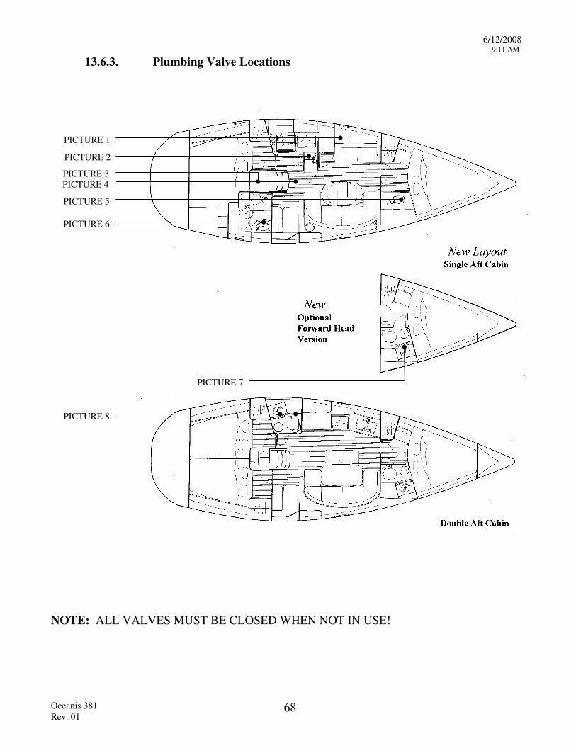
6/12/2008 9:11 AM
Oceanis 381 Rev. 01
68
13.6.3. Plumbing Valve Locations
PICTURE 1
PICTURE 2
PICTURE 3PICTURE 4
PICTURE 5
PICTURE 6
PICTURE 7
PICTURE 8
NOTE: ALL VALVES MUST BE CLOSED WHEN NOT IN USE!
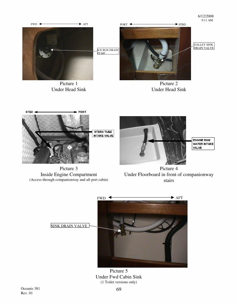
6/12/2008 9:11 AM
Oceanis 381 Rev. 01
69
ICE BOX DRAINPUMP
FWD AFT
GALLEY SINKDRAIN VALVE
STBDPORT
Picture 1 Picture 2
Under Head Sink Under Head Sink
Picture 3 Picture 4
Inside Engine Compartment (Access through companionway and aft port cabin)
Under Floorboard in front of companionway stairs
SINK DRAIN VALVE
FWD AFT
Picture 5
Under Fwd Cabin Sink (1 Toilet versions only)
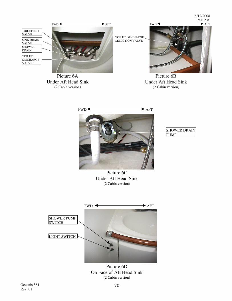
6/12/2008 9:11 AM
Oceanis 381 Rev. 01
70
AFTFWD
SHOWERDRAINVALVETOILETDISCHARGEVALVE
SINK DRAINVALVE
TOILET INLETVALVE
AFTFWD
TOILET DISCHARGESELECTION VALVE
Picture 6A Picture 6B
Under Aft Head Sink (2 Cabin version)
Under Aft Head Sink (2 Cabin version)
AFTFWD
SHOWER DRAINPUMP
Picture 6C
Under Aft Head Sink (2 Cabin version)
FWD AFT
SHOWER PUMPSWITCH
LIGHT SWITCH
Picture 6D
On Face of Aft Head Sink (2 Cabin version)
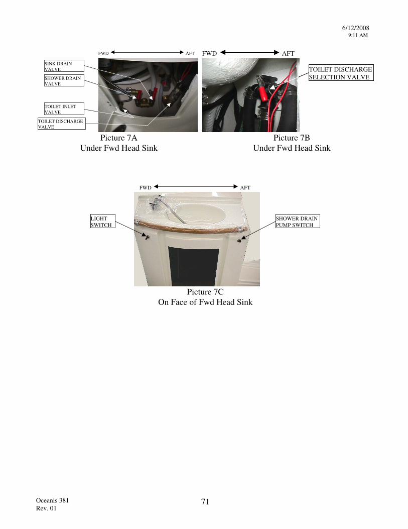
6/12/2008 9:11 AM
Oceanis 381 Rev. 01
71
FWD AFT
SINK DRAINVALVE
SHOWER DRAINVALVE
TOILET INLETVALVE
TOILET DISCHARGEVALVE
FWD AFT
TOILET DISCHARGESELECTION VALVE
Picture 7A Picture 7B
Under Fwd Head Sink Under Fwd Head Sink
LIGHTSWITCH
SHOWER DRAINPUMP SWITCH
FWD AFT
Picture 7C
On Face of Fwd Head Sink
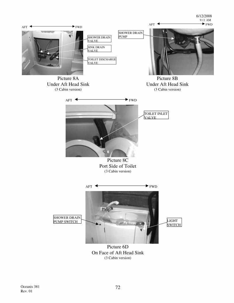
6/12/2008 9:11 AM
Oceanis 381 Rev. 01
72
FWDAFT
SHOWER DRAINVALVE
SINK DRAINVALVE
TOILET DISCHARGEVALVE
FWDAFT
SHOWER DRAINPUMP
Picture 8A Picture 8B
Under Aft Head Sink (3 Cabin version)
Under Aft Head Sink (3 Cabin version)
FWDAFT
TOILET INLETVALVE
Picture 8C
Port Side of Toilet (3 Cabin version)
FWDAFT
LIGHTSWITCH
SHOWER DRAINPUMP SWITCH
Picture 6D
On Face of Aft Head Sink (3 Cabin version)
6/12/2008 9:12 AM
Oceanis 381 Rev. 01
73
13.7. MARINE TOILET & HOLDING TANK
13.7.1. General Description The marine sanitary system consists of a marine toilet (head), (ITT- Jabsco Compact Toilet 29090-0000), a holding tank and a series of thru hull intakes, discharges and valves to control the intake of water into the head to flush the bowl either into the holding tank or overboard.
13.7.2. Head Operating Procedure
The marine heads on your Beneteau are installed below the water line, all valves must be closed after use and the selection lever on the head must be returned to the dry bowl position. Failure to do so could result on the bowl overflowing and flooding the boat with water.
1. Read the instructions for use supplied by the head manufacturer and the precautions marked on the pump.
2. Before use, make sure that the water supply thru-hull valve is open and the Y-valve is selected for discharge into the holding tank. (See section 13.7.3 for Y-valve operation)
NOTE: BY LAW YOU MUST USE A HOLDING TANK IN ALL US WATERS.
3. Check with local authorities for regional laws governing your area before selecting the overboard discharge option. If you choose overboard discharge option, be sure the discharge thru-hull valve is open before using the head. Select the overboard discharge position on the Y-valve. (See section 13.7.3 for Y-valve operation)
4. Select "Flush Bowl" with the selection lever on top of the pump body and pump the handle until the bowl is flushed clean. Return the selection lever to "Dry Bowl" and pump the handle until the bowl is dry. Limiting pump strokes will maximize the use of the holding tank.
5. CLOSE THE VALVES AFTER USE.
6/12/2008 9:12 AM
Oceanis 381 Rev. 01
74
13.7.3. Operation Of Y-Valve For Disposal Of Head Waste The head waste removal system has two options for the disposal of waste:
OPTION 1 DISPOSAL OF WASTE INTO HOLDING TANK
OPTION 2 DISPOSAL OF WASTE OVERBOARD
The Y-Valve located under the head sink controls which method of waste disposal is utilized. When the red control lever is perpendicular to the hose, that hose outlet is closed.
6/12/2008 9:12 AM
Oceanis 381 Rev. 01
75
13.7.4. Holding Tank Pump Out Procedure The holding tanks are pumped out thru deck plates located on the starboard transom and in the forward anchor locker. Consult your dealer or your marina for the closest pump out facility in your area.
1. Open the deck plate with a winch handle and insert the pump out hose into the deck fill,
2. Follow the pump out stations operating procedure to pump all of the effluent from the tank.
3. Flush the tank by pumping water thru the head into the tank or by inserting a hose into the deck fitting to add fresh water and then pump the tank again.
4. Close the deck fitting.
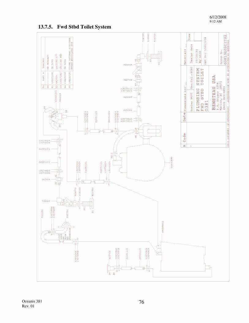
6/12/2008 9:12 AM
Oceanis 381 Rev. 01
76
13.7.5. Fwd Stbd Toilet System
R Code Date
Scale
Gen.
Design date
By
View
THIS DOCUMENT IS PROPRIETARY - REPRODUCTION
MUST BE AUTHORIZED BY BENETEAU
BENETEAU USA
P.O. Drawer 1218
Marion, SC 29571
(803) 423-4201
D:
:0
imensions in:
__
NONE
Tol.:NONE
Material: __
BADB
DWG No:
System No.
PART #
No
S0
SEALANT
S1
3M 5200
S2
LOCTITE 577
S3
LOCTITE RED
S4
3M 5230
S5
CLEAR NEUTRAL SILICONE
MOBAY BAYSILONE 400
14025200
642450
14017262
14023230
14022210
--------
NO SEALANT
S5
S0
S0
S0
S2
623700
13070024
13070024
04091121
04091121
13070024
13070024
A
BS0
04991000
13070024
13070024
04091121
04091121
13070024
13070024
G
PLUMBING SYSTEM
TOILET
S0
906120
03045005
0700131313070013
1307001313070013
025909
025909
342700
1307002413070024
04091121
04091121
1307002413070024
FWD
STBD
ITB
000CIT02
026156
04068002
026068
S2
S2
S1
824700
159000
738700
S0
S0
E13070008
13070008
LOOP
HOSE
AS
HIGH
AS
POSSIBLE
005751
130700
13070008
08
09/23/96
O381
O3813
O3813
13070024
13070024
04091121
04091121
13070024
13070024
S2
S0
738900
342800
S2
S1
824900
159100
026070
S2
D
C
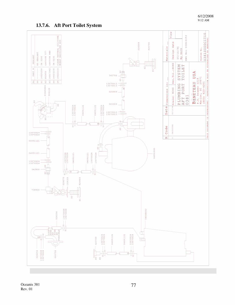
6/12/2008 9:12 AM
Oceanis 381 Rev. 01
77
13.7.6. Aft Port Toilet System
R Code Date
Scale
Gen.
Design date
By
View
THIS DOCUMENT IS PROPRIETARY - REPRODUCTION
MUST BE AUTHORIZED BY BENETEAU
BENETEAU USA
P.O. Drawer 1218
Marion, SC 29571
(803) 423-4201
D:
:PROTOTYPE
0
imensions in:
__
NONE
Tol.:NONE
Material: __
BADB
DWG No:
System No.
PART #
No
S0
SEALANT
S1
3M 5200
S2
LOCTITE 577
S3
LOCTITE RED
S4
3M 5230
S5
CLEAR NEUTRAL SILICONE
MOBAY BAYSILONE 400
14025200
642450
14017262
14023230
14022210
--------
NO SEALANT
S5
S0
S0
S0
S2
S2
S1
623700
824700
026068
13070024
13070024
04091121
04091121
13070024
13070024
13070024
13070024
04091121
04091121
13070024
13070024
A
B
D
S0
04991000
13070024
13070024
04091121
04091121
13070024
13070024
G
O10ITJ
O10000CIT10
PLUMBING SYSTEM
AFT PORT TOILET
O1
S0
S0
S0
906120
03045005
S2
S0
C
0700131313070013
1307001313070013
025909
025909
342700
738900
342800
1307002413070024
04091121
04091121
1307002413070024
S2
S1
824900
159100
026070
S2
026156
13070008
026156
04068002
38
38
38
05/14/96
05/14/96
E
13070008
13070008
13070008
LOOP
HOSE
AS
HIGH
AS
POSSIBLE
005750
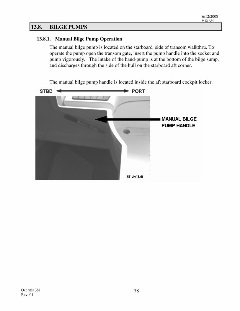
6/12/2008 9:12 AM
Oceanis 381 Rev. 01
78
13.8. BILGE PUMPS
13.8.1. Manual Bilge Pump Operation The manual bilge pump is located on the starboard side of transom walkthru. To operate the pump open the transom gate, insert the pump handle into the socket and pump vigorously. The intake of the hand-pump is at the bottom of the bilge sump, and discharges through the side of the hull on the starboard aft corner.
The manual bilge pump handle is located inside the aft starboard cockpit locker.
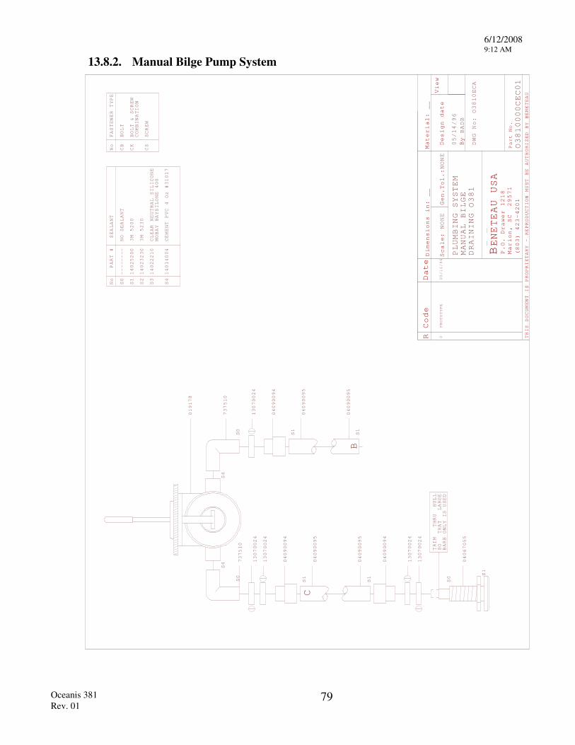
6/12/2008 9:12 AM
Oceanis 381 Rev. 01
79
13.8.2. Manual Bilge Pump System
R Code Date
Mater
Scale
Design date
By
View
THIS DOCUMENT IS PROPRIETARY - REPRODUCTION
MUST BE AUTHORIZED BY BENETEAU
BENETEAU USA
P.O. Drawer 1218
Marion, SC 29571
(803) 423-4201
Part No.
:
PROTOTYPE
0
NONE
Dimensions in:
__
ial:
Gen.Tol.:NONE
__
BADB
PLUMBING SYSTEM
DWG No:
MANUAL BILGE
DRAINING
S1
S1
S1
S1
S0
S1
TRIM
SO
BARB ONLY IS USED
THAT LARGE
THRU HULL
PART #
No
S0
SEALANT
S1
3M 5200
S2
S3
14025200
--------
NO SEALANT
No
CB
BOLT
FASTENER TYPE
CK
BOLT & SCREW
COMBINATION
CS
SCREW
14023230
3M 5230
14022210
CLEAR NEUTRAL SILICONE
MOBAY BAYSILONE
400
S4
14014004
CEMENT PVC 4 Oz #31017
13070024
04090094
04090095
04090095
13070024
13070024
04090094
04090095
04090095
04090094
13070024
13070024
B
C
0000CEC01
/96
/96
O04067055
10ECA
05/14
05/14
381
O38
O381
S0
S4
S4
S0
019178
737510
737510
6/12/2008 9:12 AM
Oceanis 381 Rev. 01
80
13.8.3. Electric Bilge Pump Operation The electric bilge pump drains both the bilge pump and the galley ice box. The pump, Y-Valve and filter are located in the pump house under the starboard aft settee in the main saloon. To drain the bilge or icebox select the correct position with the valve and turn on the pump. The pump is controlled from a switch on the main 12V panel. Be sure to clean the filter between the pump and sump carefully, at regular intervals. To clean the filter unscrew the body and wash out the filter screen.
WARNING! BE CAREFUL NOT TO WASH THE O-RING SEAL OUT OF THE FILTER.
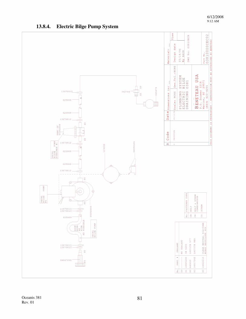
6/12/2008 9:12 AM
Oceanis 381 Rev. 01
81
13.8.4. Electric Bilge Pump System
R Code Date
Mater
Scale
Design date
By
View
THIS DOCUMENT IS PROPRIETARY - REPRODUCTION
MUST BE AUTHORIZED BY BENETEAU
BENETEAU USA
P.O. Drawer 1218
Marion, SC 29571
(803) 423-4201
Part No.
:
PROTOTYPE
0
NONE
Dimensions in:
__
ial:
Gen.Tol.:NONE
__
BADB
PLUMBING SYSTEM
ELECTRIC BILGE
DRAINING
DWG No:
S0
S0
S0
S0
S2
S0
PART #
No
S0
SEALANT
S1
3M 5200
S2
LOCTITE 577
S3
LOCTITE RED
S5
CLEAR NEUTRAL SILICONE
MOBAY BAYSILONE 400
14025200
642450
14017262
14022210
--------
NO SEALANT
DECAL
BILGE
PUMP
STRAINER #1
DECAL
BILGE
PUMP
#1
025479
3427003070012
13070012
05092000
PART OF
13070012
13070012
05092000
025909
025909
025909
025909
10ECB
10000CEC02
/96
/96
LOOP
HOSE
AS
HIGH
AS POSSIBLE
S0
S1
13 070011307001
13070011307001
DECAL
BILGE PUMP
025909
33
33
AB
C No
CB
BOLT
FASTENER TYPE
CK
BOLT & SCREW
COMBINATION
CS
SCREW
1
O
119200
04094101
04067050
05/14
05/14
O381
O38
38
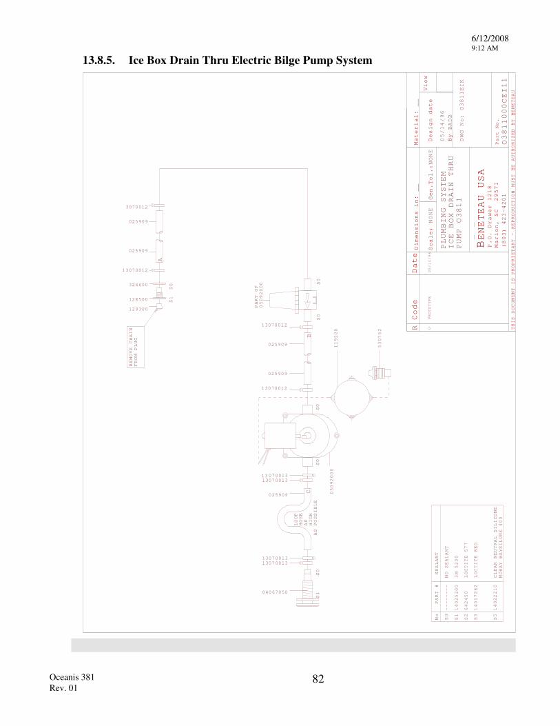
6/12/2008 9:12 AM
Oceanis 381 Rev. 01
82
13.8.5. Ice Box Drain Thru Electric Bilge Pump System
R Code Date
Mater
Scale
Design date
By
View
THIS DOCUMENT IS PROPRIETARY - REPRODUCTION
MUST BE AUTHORIZED BY BENETEAU
BENETEAU USA
P.O. Drawer 1218
Marion, SC 29571
(803) 423-4201
Part No.
:
PROTOTYPE
0
NONE
Dimensions in:
__
ial:
Gen.Tol.:NONE
__
BADB
PLUMBING SYSTEM
DWG No:
PART #
No
S0
SEALANT
S1
3M 5200
S2
LOCTITE 577
S3
LOCTITE RED
S5
CLEAR NEUTRAL SILICONE
MOBAY BAYSILONE 400
14025200
642450
14017262
14022210
--------
NO SEALANT
/96
ICE BOX DRAIN THRU
PUMP O
1O
1EIK
O1
000CEI11
S0
S0
S0
S0
05092000
PART OF
13070012
13070012
05092000
119200
025909
025909
LOOP
HOSE
AS
HIGH
AS POSSIBLE
S0
S1
13070011307001
13070011307001
025909
33
33
SS0
1128500
324600
REMOVE CHAIN
FROM PLUG
129300
13070012
3070012
025909
025909
A
BC
04067050
11
1
05/14/96
05/14
38
38
38
53
752
0

6/12/2008 9:12 AM
Oceanis 381 Rev. 01
83
13.9. SELF- DRAINING COCKPIT
The cockpit is drained thru 2 tubes located at the outboard aft corners of the cockpit. Make sure that these drain holes are not blocked.
When using the cockpit as a "workshop" plug drain holes with large cork bungs to avoid the loss of any nuts or bolts which you may accidentally drop.
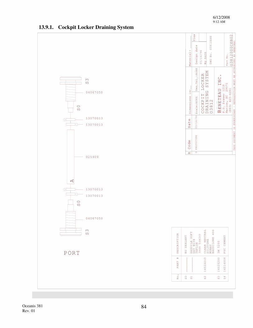
6/12/2008 9:12 AM
Oceanis 381 Rev. 01
84
13.9.1. Cockpit Locker Draining System
R Code
Material
Scale
Gen.
Design date
By
View
THIS DOCUMENT IS PROPRIETARY - REPRODUCTION
MUST BE AUTHORIZED BY BENETEAU
BENETEAU INC
P.O. Drawer 1218
Marion, SC 29571
(803) 423-4201
Part No.
Dimensions i
:n
.
Date
:
:
NONE
Tol.:
NONE
BADB
__
PROTOTYPE
_______
DWG No.
000C
S0
No.
PART #
DESCRIPTION
________
NO SEALANT
S1
________
GASOILA SOFT
SET
WITH
TEFLON
(non toxic)
S2
14022210
CLEAR NEUTRAL
SILICONE
MOBAY
BAYSILONE
400
S3
14025200
3M 5200
S4
14014004
PVC CEMENT
0
COCKPIT LOCKER
DRAINING SYSTEM
EB02
/96
OEBB
025909
1307001
1307001
1307001
1307001
3
3
3
3
PORT
S3
S3
S0
S0
A
04067050
04067050
05/14/96
05/14
3812
O3812
O3812
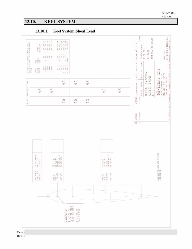
6/12/2008 9:12 AM
Oceanis 381 Rev. 01
85
13.10. KEEL SYSTEM
13.10.1. Keel System Shoal Lead
R Code Date
Material
Scale:
Gen.
Design date
By
View
THIS DOCUMENT IS PROPRIETARY - REPRODUCTION
MUST BE AUTHORIZED BY BENETEAU
BENETEAU INC
P.O. Drawer 1218
Marion, SC 29571
(803) 423-4201
Part No.
:
Dimensions in
Tol.
0PROTOTYPE
Millimeters
NONE
NONE
N/A
BADB
DWG No:
KEEL SYSTEM
PAINTED
KEEL FR
UNPAINTED
KEEL FR
BACKING
SS
ADHESIVE/SEALANT
5230
14023230
BOLT
PLATE
USE
HOLE
SAW
14mm
PART
NUMBER
FOR
KEEL
BOLT
/8
518045040
20mm
15/16
18045060
30mm
13/8
18045124
36mm
15/8
18045140
42mm
17/8
18045156
8/
5"
3/4
18045048
3/4"
15/16
18045060
7/8"
11/16
18045104
11/4"
17/16
18045128
1 1/2"
1 11/16
18045144
1 3/4"
50mm
18045201
TABLE OF HOLE SAW DIA.
TO BE USED FOR DRILLING
HULL.
HULL THICKNESS (mm)
CAST IRON
0L20SLO01
0L20
GROUND
1 x
x SS FLAT
HEAD M/SCREW
2 x 326
00
mm SS NUT
04/24/96
04/24/96
381
381
45
45
42
46
40
40
40
40
43
43
039552
036094
DACRO
20x090
017539
46650022
D22
75x75x6.5
BACKING
SS
BOLT
PLATE
DACRO
20x090
017539
D22
75x75x6.5
46650007
930600
625
56
381
O
O
O
6/12/2008 9:12 AM
Oceanis 381 Rev. 01
86
13.11. PROPANE COOKING SYSTEM
13.11.1. Propane System Description Your Beneteau is equipped with a propane combination stove and oven. This unit is located in the galley and is gimbaled for your safety and comfort in a seaway. The stove is supplied by a storage bottle located in a self draining locker in the cockpit. The pressurized gas is fed thru a regulator at the bottle which reduces the pressure and feeds the propane gas to a 12V solenoid valve. The solenoid is a remotely controlled valve which turns the flow of gas on and off from a switch located at the 12V distribution panel. A pressure gauge is located before the regulator to check the gas system.
13.11.2. Propane System Operation
WARNING! ALWAYS LEAVE BOTH THE SOLENOID VALVE AND THE VALVE ON THE GAS BOTTLE CLOSED WHEN THE STOVE IS NOT BEING USED.
1. Read and follow the instructions printed on the propane warning labels located at the appliance and under the lid of the gas storage locker.
2. Be sure all burner and oven knobs are in the off position before attempting to operate the galley stove.
3. Activate the main 12V system and be sure the solenoid switch is in the off position.
4. Open the supply valves and test the system for leaks following the instructions on the locker warning label.
5. Light the appliance in accordance with the stove manufactures procedures. Generally each burner is lit by turning the burner control knob to the lighting position and then pushing the knob in. A safety thermocouple will keep the valve open as long as the burner remains lit. If the flame goes out it will stop the gas flow to the burner.
Note: If the odor of gas is detected at any, time turn off all electrical and mechanical systems, extinguish any open flames and immediately check for a propane leak. Propane is a heavy gas and may settle in the bilge which represents an explosion and fire hazard.
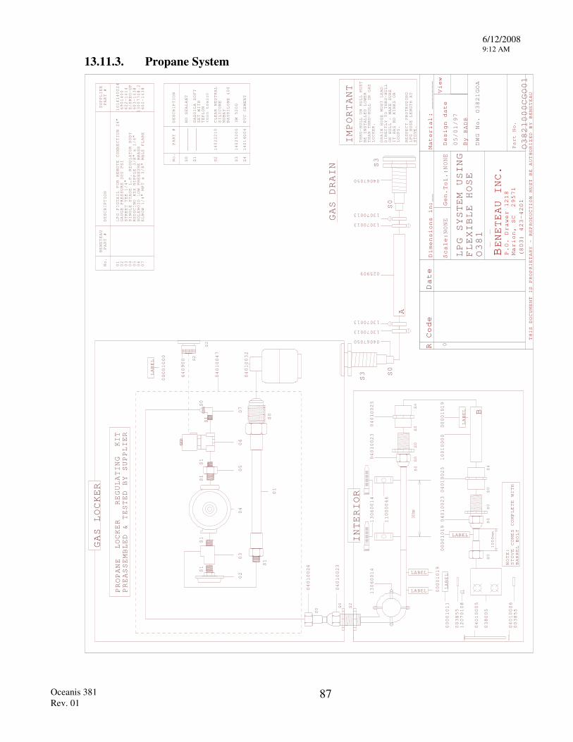
6/12/2008 9:12 AM
Oceanis 381 Rev. 01
87
13.11.3. Propane System
R Code
Material
Scale
Gen.
Design date
By
View
THIS DOCUMENT IS PROPRIETARY - REPRODUCTION
MUST BE AUTHORIZED BY BENETEAU
BENETEAU INC
P.O. Drawer 1218
Marion, SC 29571
(803) 423-4201
Part No.
Dimensions i
:n
.
Date
:
:
NONE
Tol.:
NONE
BADB
__
_______
DWG No.
GAS LOCKER
S0
SO
INTERIOR
S2
LPG SYSTEM USING
FLEXIBLE HOSE
IMPORTANT
THRU-HULL ON HULL MUST
BE INSTALLED LOWER
THAN THRU-HULL IN GAS
LOCKER.
DRAIN HOSE MUST LEAD
DIRECTLY TO THRU-HULL
ON HULL - MAKE SURE
IT HAS NO KINKS
OR
LOOPS.
RESPECT PROTRUDING
LPG HOSE LENGTH AT
STOVE.
PROPANE
PREASSEMBLED & TESTED BY SUPPLIER
LOCKER REGULATING KIT
S0
S3
S0
S3
S2
S2
LABEL
LABEL
LABEL
S0
S0
S0
S0
S4
S0
S0
S0
S0
S4
1000mmLABEL
LABEL
LABEL
S0
No.
PART #
DESCRIPTION
________
NO SEALANT
S1
________
GASOILA SOFT
SET
WITH
TEFLON
(non toxic)
S2
14022210
CLEAR NEUTRAL
SILICONE
MOBAY
BAYSILONE
400
S3
14025200
3M 5200
S4
14014004
PVC CEMENT
GAS DRAIN
00001000
04010047
04010032
040100
04010023
13060014
13060014
11000046
04010023
04010025
00001019
10010000
04010025
04010023
00001019
00001019
00001011
A
B
300mm
000CGO01
S1
S1
S1
S1
S1
S0
01
02
03
04
05
06
07
S1
S0
BENETEAU
PART #
No.
DESCRIPTION
0 0 0 0 0 0 0
LPG PIGTAIL FOR REMOTE CONNECTION 24"
STREET TEE 1/4"
1 2 3 4 5 6 7
SUPPLIER
PART #
1014140224
GAUGE PRESSURE 300 PSI
6901400
622-1414
SINGLE STAGE L.P. REGULATOR BODY S/SREG-UP
REDUCING HEX NIPPLE 3/8" x 1/4"
603-1438
SOLENOID LOW PRESSURE BRASS
13007708.2
ELBOW 1/4" MPT x 3/8" MALE FLARE
602-1438
STOVE COMES COMPLETE WITH
BARREL BOLT
NOTE:
025909
1307001
1307001
1307001
1307001
3
3
3
3
04067050
04067050
1GOA
640900
2
12070108
04010005
04010006
038005
O381
O38
O38
1
6
0
05/01/97
2
2
003855
003855
6/12/2008 9:12 AM
Oceanis 381 Rev. 01
88
13.12. 12 VOLT SYSTEM
13.12.1. 12 Volt Distribution Panel Operation The 12V power from your batteries is distributed throughout your boat via a distribution panel. This panel separates the current into separate circuits. Each circuit is protected by an individual breaker switch which allows you to turn the individual circuits on or off as needed at the panel. Each breaker switch has an individual amperage rating which it is designed to trip at in case it is overloaded.
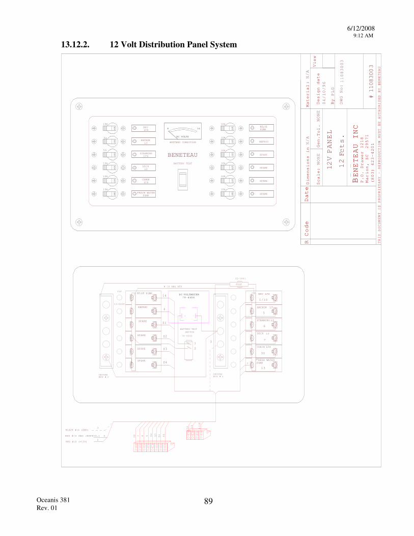
6/12/2008 9:12 AM
Oceanis 381 Rev. 01
89
13.12.2. 12 Volt Distribution Panel System
R Code Date
Material
Scale:
Gen.
Design date
By
View
THIS DOCUMENT IS PROPRIETARY - REPRODUCTION
MUST BE AUTHORIZED BY BENETEAU
BENETEAU INC
P.O. Drawer 1218
Marion, SC 29571
(803) 423-4201
:
Dimensions in
Tol.
NONE
NONE
N/A
DWG No:
PLG
0/96
110830
#
N/A
PANEL
2V
1 1Fcts.
2
03
11083003
4/10
LTS
LT
STEAMING
ANCHOR
LTS
SPARE
10A
DC VOLTS
8 16
REFRIG
SPARE
SPARE
BATTERY CONDITION
BATTERY TEST
BENETEAU
CABIN
DECK
LTS
LT
NAV
PUMPFRESH WATER
PUMPBILGE
SPARE
OFF
10A
10A
10A
OFF
5A
OFF
OFF
OFF
OFF
A5
10A
OFF
10A
10A
10A
OFF
OFF
OFF
OFF
OFF
10A
10A
79-4406DC VOLTMETER
BATTERY TESTSWITCH
70-6043
GROUND BUS #
GROUND BUS # 2 1
FUSE
35-1041
BILGE PUMP
REFRIG
SPARE
SPARE
SPARE
SPARE
NAV LTS
ANCHOR LT
STEAMING LT
RESH WATPUMP
ER
CABIN LTS
LTDECK
2
+ -
TYP
13-0100
# 10 AWG RED
1
2
3
14
4
Z1
Z2
Z3
Z4
1/10
5
6
7
30
13
14 13
1/10
30 7 6 5 Z4
Z3
Z2 Z1
2
3
RED #14 AWG (REFRIG.) 4
RED #10 (+12V)
BLACK #14 (GND)
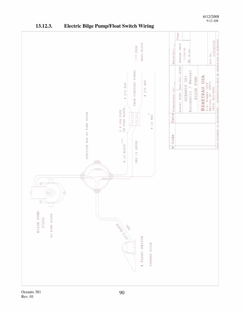
6/12/2008 9:12 AM
Oceanis 381 Rev. 01
90
13.12.3. Electric Bilge Pump/Float Switch Wiring
R Code Date
Mater
Scale
Design date
By
View
THIS DOCUMENT IS PROPRIETARY - REPRODUCTION
MUST BE AUTHORIZED BY BENETEAU
BENETEAU USA
P.O. Drawer 1218
Marion, SC 29571
(803) 423-4201
Part No.
:
NONE
Dimensions in:
__
ial:
Gen.Tol.:NONE
__
P.LG
Automatic
7/
96
O381ECO2E
OCEANIS 381
/ Manual
BILGE PUMP
24/
FROM CONSTANT POWER.
# 270 BLK
# 270 RED
2 X 10A FUSE
ON FUSE BLOCK.
# 14 RED
JUNCTION BOX AT PUMP HOUSE
2 BLACK
RED
# FLOAT SWITCH16/
BILGE PUMP
37202
AT PUMP HOUSE
FORWARD BILGE
# 14 BLACK ***
*
WAGO BLOCK
***
FROM
RED 14 GAUGE
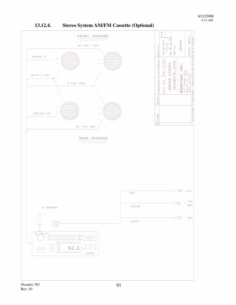
6/12/2008 9:12 AM
Oceanis 381 Rev. 01
91
13.12.4. Stereo System AM/FM Cassette (Optional)
R Code D
te
millimeters Material
Scale
Gen. Tol.
Design date
By
View
THIS DOCUMENT IS PROPRIETARY - REPRODUCTION
MUST BE AUTHORIZED BY BENETEAU
BENETEAU INC
P.O. Drawer 1218
Marion, SC 29571
(803) 423-4201
Dimensions i
:n
.
a
N/A
N/A
DWG No:
System:
SYST.
CASSETTE,
RH01
P.L.G
CD SHUTTLE CONTROL SCC HEAD
ONVOL
FAD
TREBLE BASS
+ - +-92.3
FM1
FM2
FM3AM
JENSEN
FRONT SPEAKER
REAR SPEAKER
RED
YELLOW
BLACK
CST
PWR
WH/BLK L1
WHITE L COM-
R COM- GRAY
R2+ VIO/ BLK
GRN/BLK L2+
RF= GRY / BLK
7/24/96
JENSEN
12V+
- NEG
+
TO ANTENNA
F LTER I
& FUSE
JENSEN STEREO
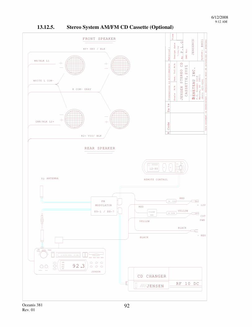
6/12/2008 9:12 AM
Oceanis 381 Rev. 01
92
13.12.5. Stereo System AM/FM CD Cassette (Optional)
R Code D
te
millimeters Material
Scale
Gen. Tol.
Design date
By
View
THIS DOCUMENT IS PROPRIETARY - REPRODUCTION
MUST BE AUTHORIZED BY BENETEAU
BENETEAU INC
P.O. Drawer 1218
Marion, SC 29571
(803) 423-4201
Dimensions i
:n
.
a
N/A
N/A
DWG No:
System:
STEREO
CD
SYST.
CASSETTE,
RH01
P.L.G
RF 10 DC JENSEN
CD CHANGER
CD SHUTTLE CONTROL SCC HEAD
ONVOL
FAD
TREBLE BASS
+ - +-92.3
FM1
FM2
FM3AM
JENSEN
89-1 / 88-7
MODULATOR
FM
12-00
FRONT SPEAKER
REAR SPEAKER
TZ
OFF
ON
DI TR
SCH
RP
SHU
FILTER
BOX5A FUSE
2 FUSEA
YELLOW
RED
YELLOW
BLACK
RED
BLACK
+ 12V
CST
PWR
- NEG
REMOTE CONTROLTO
WH/BLK L1
WHITE L COM-
R COM- GRAY
R2+ VIO/ BLK
GRN/BLK L2+
RF= GRY / BLK
JENSEN
7/24/96
JENSENCD
ANTENNA
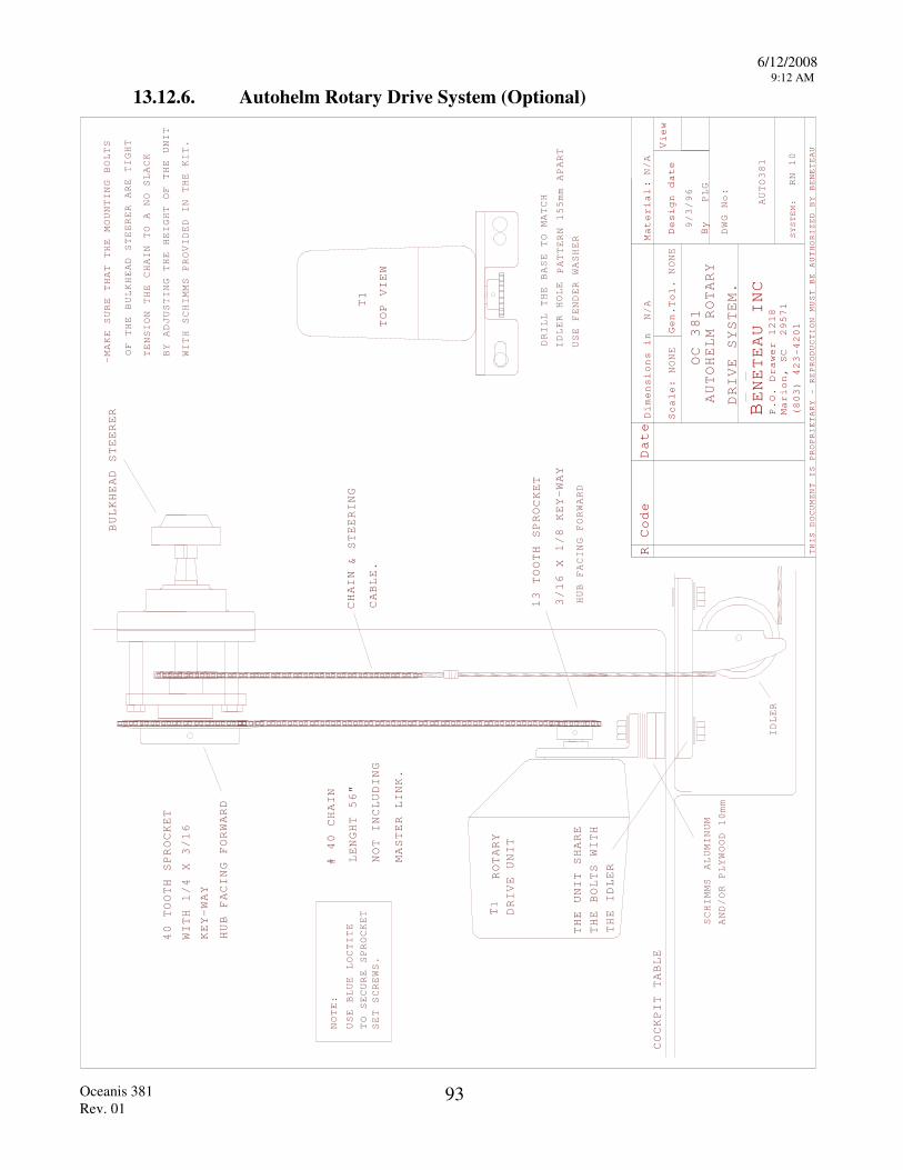
6/12/2008 9:12 AM
Oceanis 381 Rev. 01
93
13.12.6. Autohelm Rotary Drive System (Optional)
R Code Date
Material
Scale:
Gen.
Design date
By
View
THIS DOCUMENT IS PROPRIETARY - REPRODUCTION
MUST BE AUTHORIZED BY BENETEAU
BENETEAU INC
P.O. Drawer 1218
Marion, SC 29571
(803) 423-4201
:
Dimensions in
Tol.
NONE
NONE
N/A
DWG No:
SYSTEM:
N/A
PLG
96
AUTOHELM ROTARY
DRIVE SYSTEM.
CHAIN& STEERING
CABLE.
13 TOOTH SPRO
# 40 CHAIN
T
TOP VIEW
OC 381
AUTO381
CKET
ROTARY
T1
DRIVE UNIT
THE BOLTS WITH
THE UNIT SHARE
THE IDLER
IDLER HOLE
40 TOOTH SPROCKET
NOTE:
TO SECURE SPROCKET
USE BLUE LOCTITE
SET SCREWS.
COCKPIT TABLE
HUB FACING FORWARD
3/16 X 1/8 KEY-WAY
IDLER
PATTERN 155mm APART
HUB FACING FORWARD
KEY-WAY
WITH 1/4 X 3/16
RN 10
SCHIMMS
ALUMINUM
AND/OR PLYWOO
USE FENDER WASHER
DRILL THE BASE TO MATCH
1
9/3/
LENGHT 56"
NOT INCLUDING
MASTER LINK.
BULKHEAD STEERER
D 10mm
OF THE BULKHEAD STEERER ARE TIGHT
TENSION
THE CHAIN TO
A NO SLACK
BY ADJUSTING THE HEIGHT OF THE UNIT
WITH SCHIMMS PROVIDED IN THE KIT.
-MAKE SURE THAT THE MOUNTING BOLTS
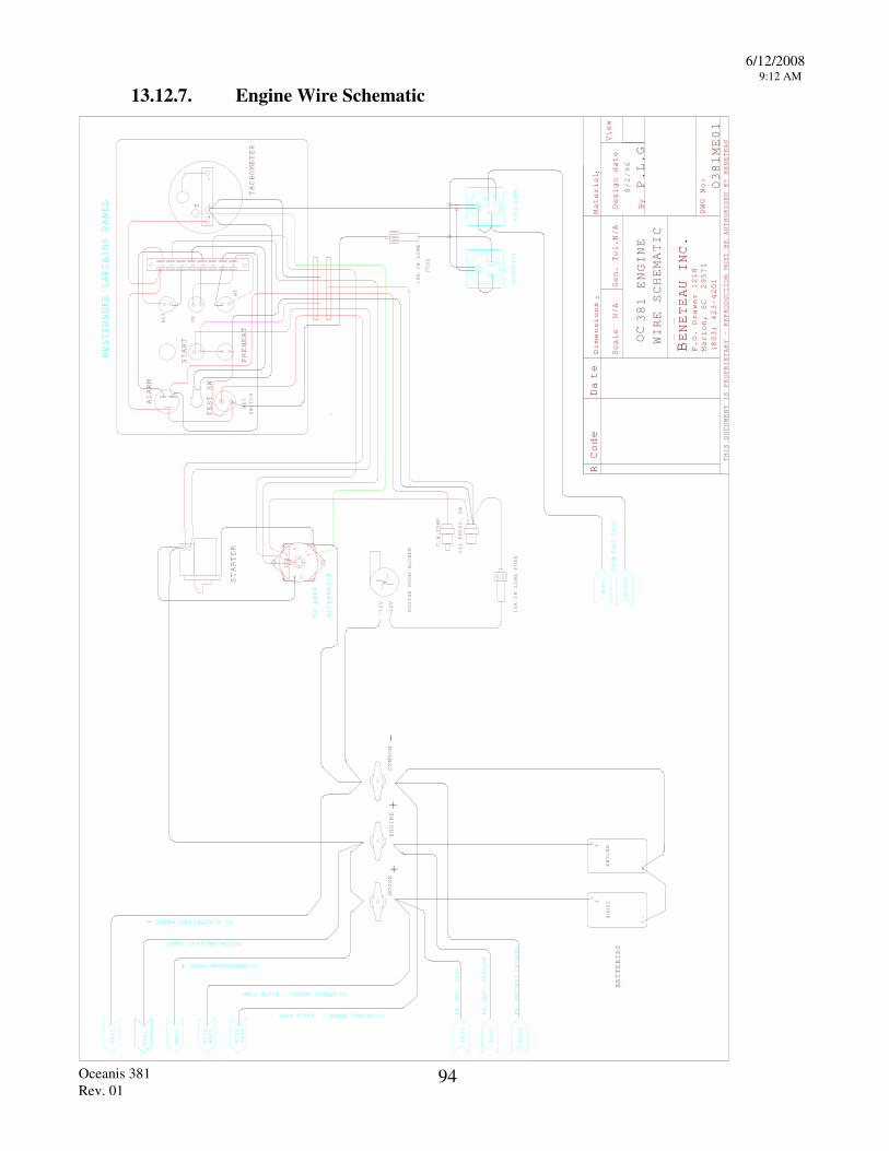
6/12/2008 9:12 AM
Oceanis 381 Rev. 01
94
13.12.7. Engine Wire Schematic
RY
TEREO MEMOR
TO ELECTRICAL PANEL
BILGE PUMP /
BILGE PUMP Y /
FA02
FA02
FA02
RH01
EC02
RH01
EC02
-12V
B+
T
-
+
HOURMETER
1 2 3 4 5 6 7 8
+-
-
S
TACHOMETER
ALARM
TEST SW
START
PREHEAT
ALT
OP
WT
-G +
FUEL TANK
AMPS
ALTERNATOR
50
STARTER
SWITCH
WESTERBEKE CAPTAINS PANEL
KEY
FUSE
10A IN LINE
+
TO ELECTRICAL PANEL -
MOTOR BATTERY TEST
FROM FUEL TANK
MCE01
MCE01
BATTERIES
HOUSE
ENGINE
TO STEREO MEMO
TO S
FR. BAT. CHGR.
FR. BAT. CHARGER
FR. BATTERY CHARGER
FA03
FA03
FA03
+COMMON -
C.W.
OIL PR
TEMP
ESS. SW
ENGINE ROOM BLOWER
+12V
-12V
10A IN LINE FUSE
HOUSE
ENGINE+
R Code D
te
Material
Scale
Gen. Tol.
Design date
By
View
THIS DOCUMENT IS PROPRIETARY - REPRODUCTION
MUST BE AUTHORIZED BY BENETEAU
BENETEAU INC
P.O. Drawer 1218
Marion, SC 29571
(803) 423-4201
Dimensions
.
a
N/A
N/A
::
WIRE SCHEMATIC
ENGINE
P.L.G
381
OC
8/2/96
DWG No: O381ME01
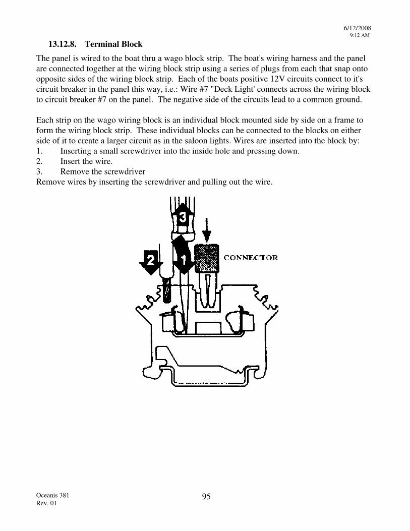
6/12/2008 9:12 AM
Oceanis 381 Rev. 01
95
13.12.8. Terminal Block The panel is wired to the boat thru a wago block strip. The boat's wiring harness and the panel are connected together at the wiring block strip using a series of plugs from each that snap onto opposite sides of the wiring block strip. Each of the boats positive 12V circuits connect to it's circuit breaker in the panel this way, i.e.: Wire #7 "Deck Light' connects across the wiring block to circuit breaker #7 on the panel. The negative side of the circuits lead to a common ground. Each strip on the wago wiring block is an individual block mounted side by side on a frame to form the wiring block strip. These individual blocks can be connected to the blocks on either side of it to create a larger circuit as in the saloon lights. Wires are inserted into the block by: 1. Inserting a small screwdriver into the inside hole and pressing down. 2. Insert the wire. 3. Remove the screwdriver Remove wires by inserting the screwdriver and pulling out the wire.
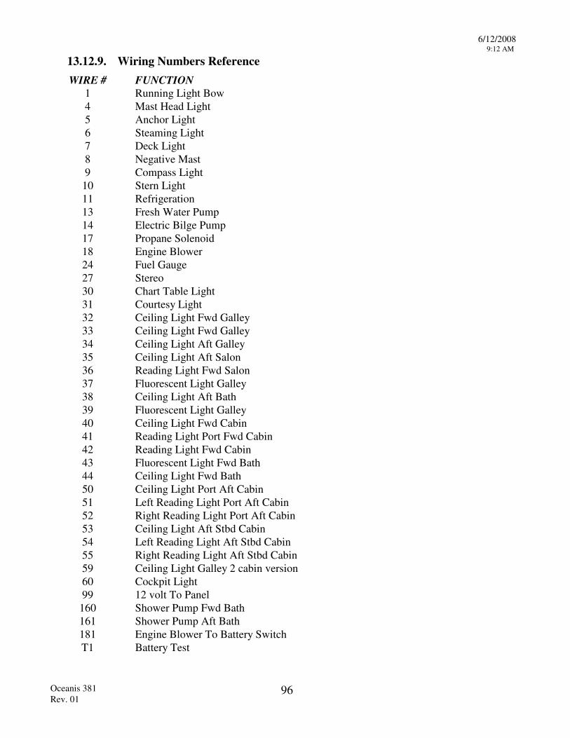
6/12/2008 9:12 AM
Oceanis 381 Rev. 01
96
13.12.9. Wiring Numbers Reference WIRE # FUNCTION
1 Running Light Bow 4 Mast Head Light 5 Anchor Light 6 Steaming Light 7 Deck Light 8 Negative Mast 9 Compass Light
10 Stern Light 11 Refrigeration 13 Fresh Water Pump 14 Electric Bilge Pump 17 Propane Solenoid 18 Engine Blower 24 Fuel Gauge 27 Stereo 30 Chart Table Light 31 Courtesy Light 32 Ceiling Light Fwd Galley 33 Ceiling Light Fwd Galley 34 Ceiling Light Aft Galley 35 Ceiling Light Aft Salon 36 Reading Light Fwd Salon 37 Fluorescent Light Galley 38 Ceiling Light Aft Bath 39 Fluorescent Light Galley 40 Ceiling Light Fwd Cabin 41 Reading Light Port Fwd Cabin 42 Reading Light Fwd Cabin 43 Fluorescent Light Fwd Bath 44 Ceiling Light Fwd Bath 50 Ceiling Light Port Aft Cabin 51 Left Reading Light Port Aft Cabin 52 Right Reading Light Port Aft Cabin 53 Ceiling Light Aft Stbd Cabin 54 Left Reading Light Aft Stbd Cabin 55 Right Reading Light Aft Stbd Cabin 59 Ceiling Light Galley 2 cabin version 60 Cockpit Light 99 12 volt To Panel
160 Shower Pump Fwd Bath 161 Shower Pump Aft Bath 181 Engine Blower To Battery Switch T1 Battery Test
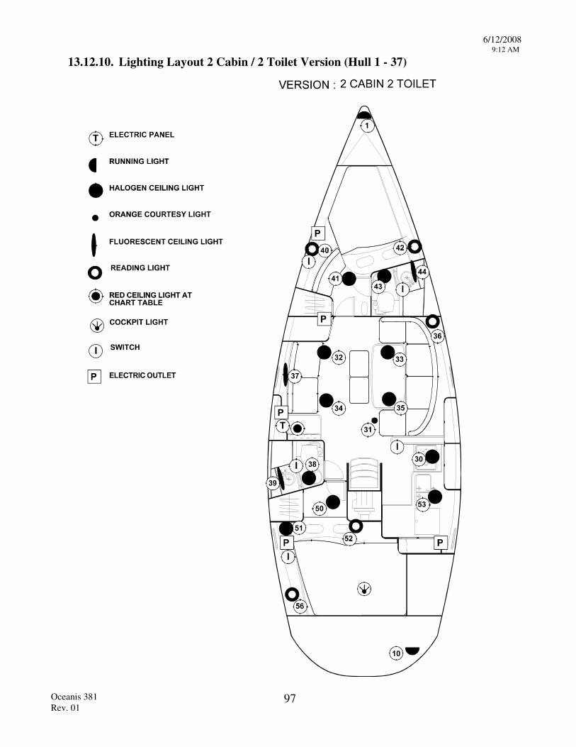
6/12/2008 9:12 AM
Oceanis 381 Rev. 01
97
13.12.10. Lighting Layout 2 Cabin / 2 Toilet Version (Hull 1 - 37)
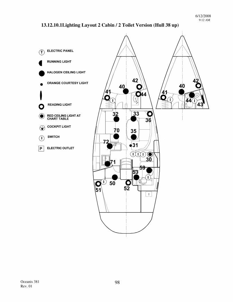
6/12/2008 9:12 AM
Oceanis 381 Rev. 01
98
13.12.10.1Lighting Layout 2 Cabin / 2 Toilet Version (Hull 38 up)
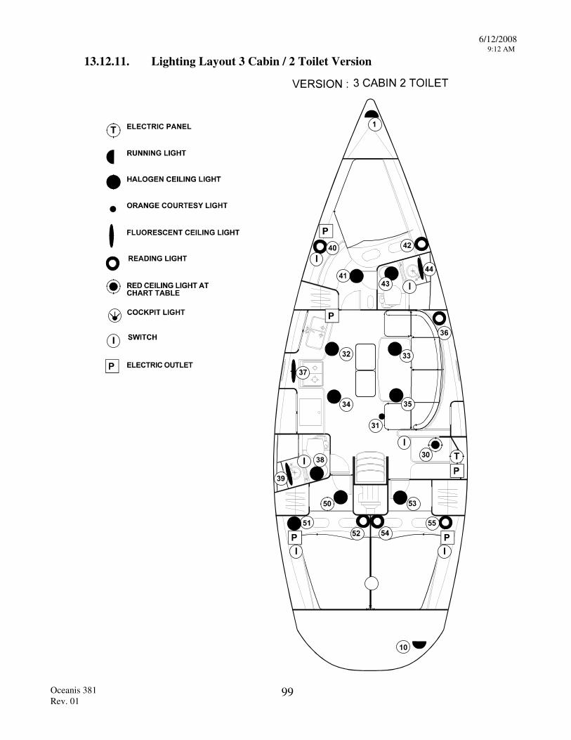
6/12/2008 9:12 AM
Oceanis 381 Rev. 01
99
13.12.11. Lighting Layout 3 Cabin / 2 Toilet Version
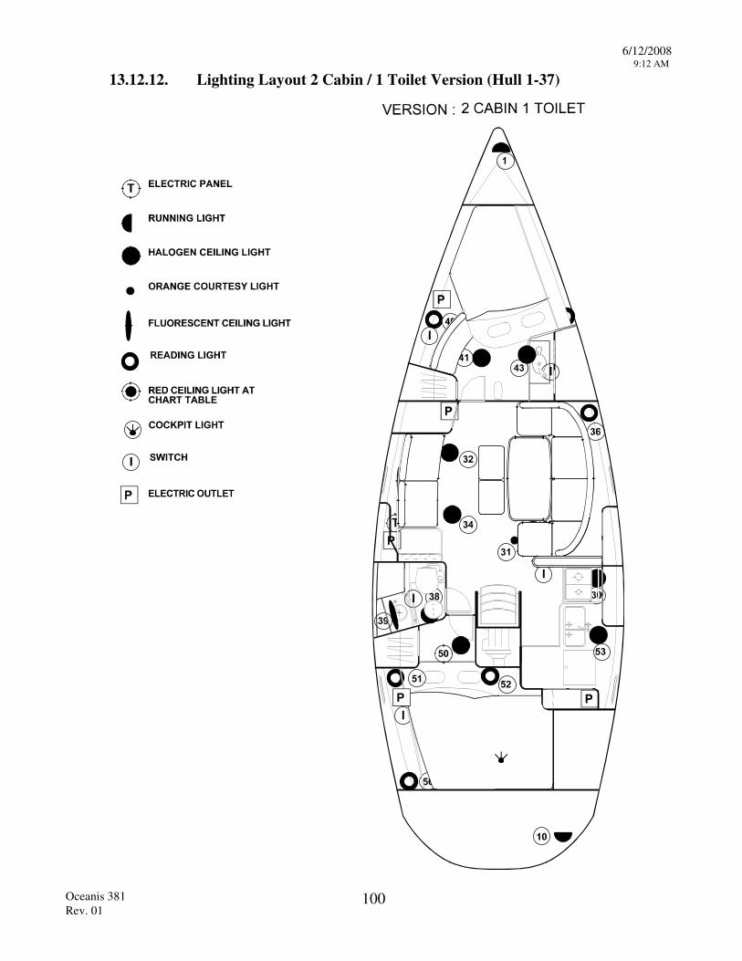
6/12/2008 9:12 AM
Oceanis 381 Rev. 01
100
13.12.12. Lighting Layout 2 Cabin / 1 Toilet Version (Hull 1-37)

6/12/2008 9:12 AM
Oceanis 381 Rev. 01
101
13.12.13. Lighting Layout 3 Cabin / 1 Toilet Version
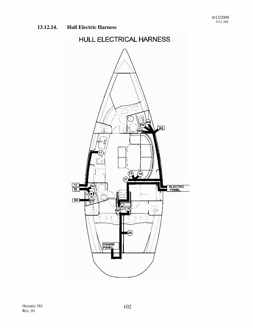
6/12/2008 9:12 AM
Oceanis 381 Rev. 01
102
13.12.14. Hull Electric Harness
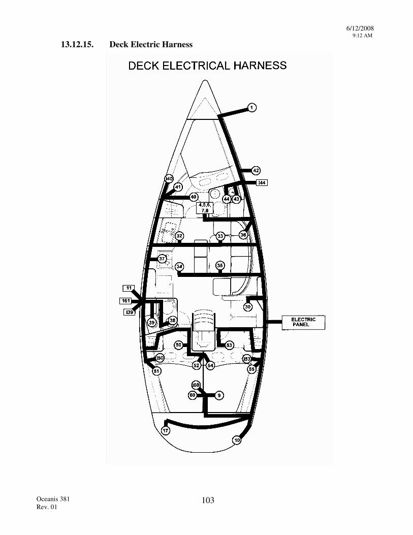
6/12/2008 9:12 AM
Oceanis 381 Rev. 01
103
13.12.15. Deck Electric Harness
6/12/2008 9:12 AM
Oceanis 381 Rev. 01
104
13.12.16. Batteries
The amount of charge the battery is receiving can be checked on the voltmeter, which is graduated in either volts. This should be done when the battery is cold and has not been recharged or used for several hours beforehand. A reading of less than 11.5 V means that recharging is necessary.
WARNING! NEVER OPERATE ISOLATING SWITCHES WHILE THE ENGINE IS RUNNING - DOING SO COULD DAMAGE THE ALTERNATOR DIODES AND REGULATOR BEYOND REPAIR.
13.12.17. 12V Charging System The batteries must be recharged by one of the following systems:
13.12.17.1. Alternator A belt drive alternator is mounted to the engine which produces 12V as needed by the batteries when the engine is running. The output of the alternator is wired to the battery switches.
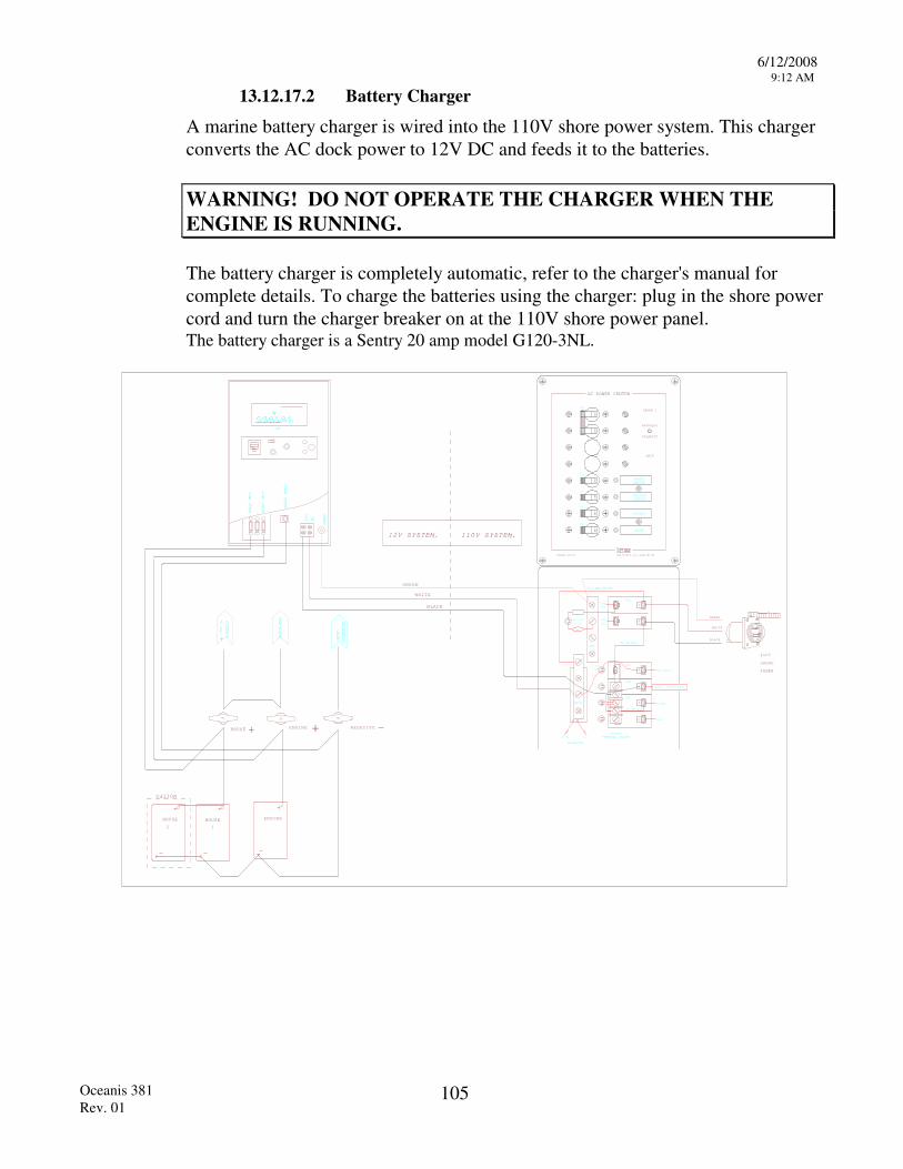
6/12/2008 9:12 AM
Oceanis 381 Rev. 01
105
13.12.17.2 Battery Charger
A marine battery charger is wired into the 110V shore power system. This charger converts the AC dock power to 12V DC and feeds it to the batteries.
WARNING! DO NOT OPERATE THE CHARGER WHEN THE ENGINE IS RUNNING. The battery charger is completely automatic, refer to the charger's manual for complete details. To charge the batteries using the charger: plug in the shore power cord and turn the charger breaker on at the 110V shore power panel.
The battery charger is a Sentry 20 amp model G120-3NL.
SENTRY
+
-
PANEL
ENGINE
0 20 30
SEN TRY
BAT #2
BAT #1
NEG BAT
L1
GRD
N
OPTION
12 V
+
110V
SHORE
POWER
Bass Products, Inc., Salem, MA, USABeneteau 11083101
AC POWER CENTER
SHORE 1
REVERSED
POLARITY
SHIP
OFF
OFF
OFF
OFF
OFF
OFF
15
15
30
OUTLETS
SPARE
WATERHEATER
BATTERYCHARGER
15
10
GND
NEUT
BACKLITE
SPARE
OUTLETS
30A
15A
10A
15A
#14 AWG BLACK
MOV
REV. POL.
13-0204
#12 AWG WHITE
LINE
NEUT
LINE
HOT
13-0123
TYP
#12 AWG BLACK
+12VDC GNDOUTLET
TERMINAL BLOCK
WATER HEATER
ENGINE +
ENGINEHOUSE
HOUSE + NEGATIVE -
HOUSE
2 1
SYSTEM. 110V SYSTEM.12V
NEG
COMMON
BLACK
WHITE
GREEN
B A T . C H A R G E R
GREEN
WHITE
BLACK
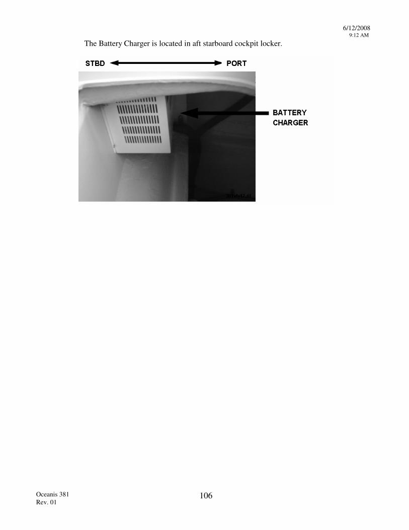
6/12/2008 9:12 AM
Oceanis 381 Rev. 01
106
The Battery Charger is located in aft starboard cockpit locker.
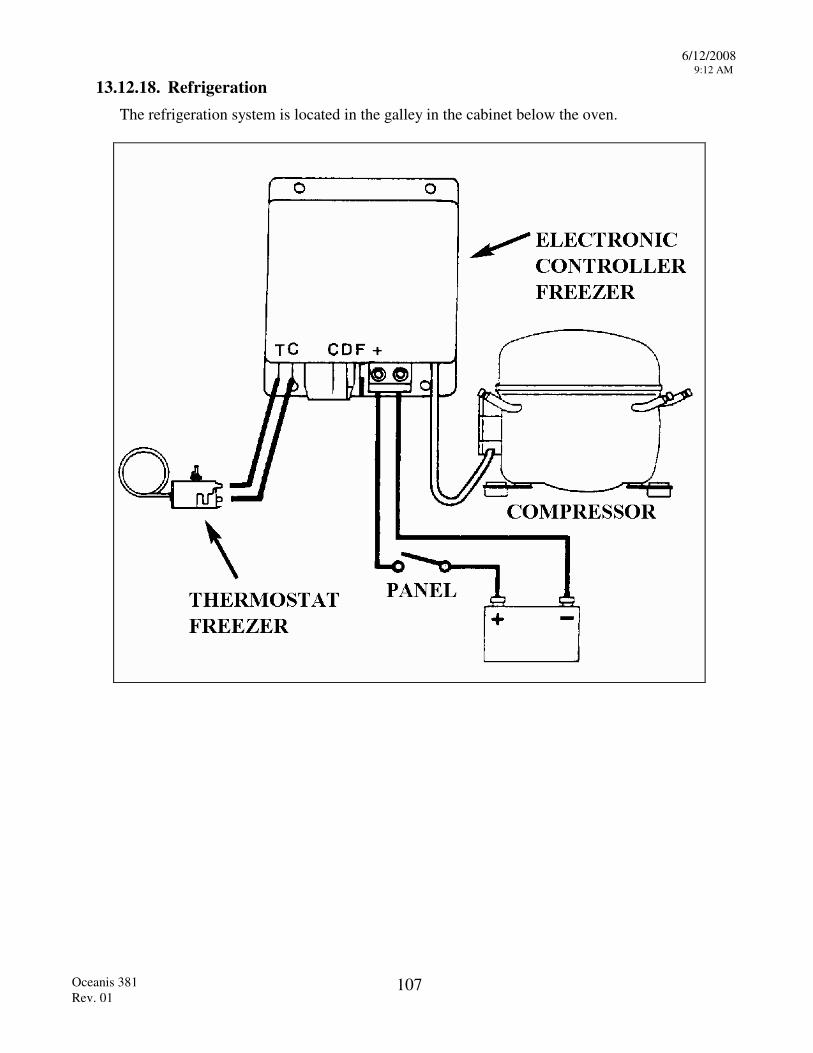
6/12/2008 9:12 AM
Oceanis 381 Rev. 01
107
13.12.18. Refrigeration The refrigeration system is located in the galley in the cabinet below the oven.
6/12/2008 9:12 AM
Oceanis 381 Rev. 01
108
13.12.19. Windlass Operation The windlass is used to raise and lower your ground tackle (anchors, chains and rodes), refer to the windlass owners manuals for proper operation. As a general guide please observe the following procedures. Control the speed of the chain running over the gypsy as the anchor is being released.
CAUTION! ALLOWING THE CHAIN TO RELEASE FREELY MAY CAUSE THE CHAIN TO JUMP FROM THE GYPSY DAMAGING THE WINDLASS, THE BOAT OR CAUSE PERSONAL INJURY.
Set the anchor by engaging the engine in reverse briefly. Do not set the anchor by pulling in with the windlass.
Always make the anchor rode fast on a cleat when the anchor is set. Do not rely on the windlass brake to hold the boat.
WARNING! THE MOTION OF THE BOAT AT ANCHOR CAN CAUSE LOADS ON THE ANCHOR RODE THAT MAY DAMAGE THE WINDLASS.
Always motor the boat up to the anchor as you take in on the rode.
WARNING! NEVER PULL THE BOAT UP TO THE ANCHOR WITH THE WINDLASS.
WARNING! NEVER BREAK THE ANCHOR OUT USING THE WINDLASS, CLEAT THE RODE OFF AND USE THE ENGINE TO BREAK OUT THE ANCHOR.
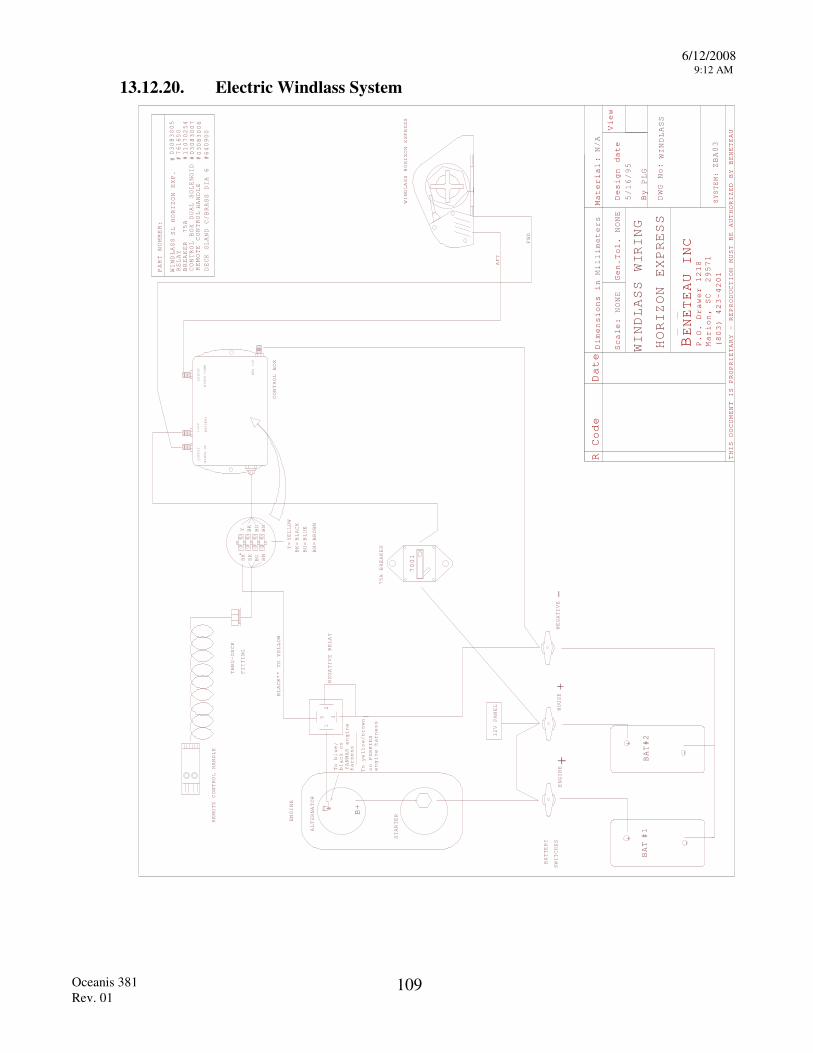
6/12/2008 9:12 AM
Oceanis 381 Rev. 01
109
13.12.20. Electric Windlass System
R Code Date
Material
Scale:
Gen.
Design date
By
View
THIS DOCUMENT IS PROPRIETARY - REPRODUCTION
MUST BE AUTHORIZED BY BENETEAU
BENETEAU INC
P.O. Drawer 1218
Marion, SC 29571
(803) 423-4201
:
Dimensions in
Tol.
Millimeters
NONE
NONE
N/A
DWG No:
PLG
SYSTEM:ZBA03
--
NEGATIVE
ENGINE
BAT#2
BAT #1
+
+
ALTERNATOR
STARTER
ENGINE
B+
700
A BREAKER
1 2
35
RELAY
NEGATIVE
WINDLASS HORIZON EXPRESS
REMOTE CONTROL HANDLE
12V PANEL
CONTROL BOX
AFT
FWD
BLACK** TO YELLOW
OUTPUT
WINCH UP
+12V
BATTERY
OUTPUT
WINCH DOWN
NEG 12V
Y BK
BU
BN
BN
BUBK
BK*
Y=
BK=
BU=
BN=
YELLOW
BLACK
BLUE
BROWN
To b
harness
lue
black on
YANMAR engine
/
on PERKINS
engine harness
To yellow/brown
PART NUMBER:
WINDLASS
RELAY
BREAKER
## # #CONTROL BOX DUAL SOLENOID
REMOTE CONTROL
#
03083005
761650
1107025
03083007
03083006
HANDLE
SL HORIZON EXP.
BATTERY
SWITCHES
WIND
+
-
HOUSE +
75A
4
WIRING
HORIZON EXPRESS
5/16/95 WINDLASS
75
1
DECK GLAND C/BRASS DIA 6 #640900
LASS
THRU-DECK
FITTING
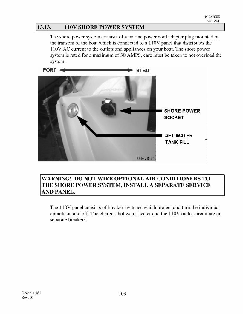
6/12/2008 9:13 AM
Oceanis 381 Rev. 01
109
13.13. 110V SHORE POWER SYSTEM
The shore power system consists of a marine power cord adapter plug mounted on the transom of the boat which is connected to a 110V panel that distributes the 110V AC current to the outlets and appliances on your boat. The shore power system is rated for a maximum of 30 AMPS, care must be taken to not overload the system.
WARNING! DO NOT WIRE OPTIONAL AIR CONDITIONERS TO THE SHORE POWER SYSTEM, INSTALL A SEPARATE SERVICE AND PANEL.
The 110V panel consists of breaker switches which protect and turn the individual circuits on and off. The charger, hot water heater and the 110V outlet circuit are on separate breakers.
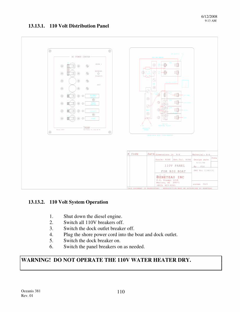
6/12/2008 9:13 AM
Oceanis 381 Rev. 01
110
13.13.1. 110 Volt Distribution Panel
R Code Date Material
Scale: Gen. Design date
By
View
THIS DOCUMENT IS PROPRIETARY - REPRODUCTION MUST BE AUTHORIZED BY BENETEAU
BENETEAU INCP.O. Drawer 1218Marion, SC 29571
(803) 423-4201
: Dimensions in
Tol.
NONE NONE
N/A
DWG No:
SYSTEM:
N/A
PLG
FA
4/1 /96
Bass Products, Inc., Salem, MA, USABeneteau 11083101
AC POWER CENTER
SHORE 1
REVERSED
POLARITY
SHIP
OFF
OFF
OFF
OFF
OFF
OFF
15
15
15
10
30
BATTERYCHARGER
OUTLETS
WATERHEATER
SPARE
GND
NEUT
BACKLITE
SPARE
OUTLETS
WATER HEATER
BATT CHARG
30A
15A
10A
15A
#14 AWG BLACK
MOV
REV. POL.
#12 AWG WHITE
LINE
NEUT
LINE
HOT
13-0123
TYP
+12VDC GND
89-2230-2
SHOWN WITH BACK COVER REMOVED
OUTLETTERMINAL BLOCK
#12 A W G B L A C K
13 - 0 2 0 4
POWER
1
25
110V PANEL
BIG BOAT FOR 11083101
13.13.2. 110 Volt System Operation 1. Shut down the diesel engine. 2. Switch all 110V breakers off. 3. Switch the dock outlet breaker off. 4. Plug the shore power cord into the boat and dock outlet. 5. Switch the dock breaker on. 6. Switch the panel breakers on as needed.
WARNING! DO NOT OPERATE THE 110V WATER HEATER DRY.
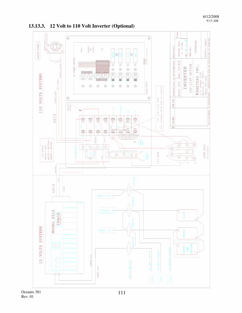
6/12/2008 9:13 AM
Oceanis 381 Rev. 01
111
13.13.3. 12 Volt to 110 Volt Inverter (Optional)
R Code D
te
millimeters Material
Scale
Gen. Tol.
Design date
By
View
THIS DOCUMENT IS PROPRIETARY - REPRODUCTION
MUST BE AUTHORIZED BY BENETEAU
Dimensions i
:n
a
N/A
N/A
DWG No:
P.L.G
NEG.ENGINE
110 VOLTS SYSTEMS
Bass P
rodu
cts,
Inc.,
Sal
em,
MA, US
A
AC POWER CENTER
SHORE 1
REVERSED
POLARITY
SHIP
OFF OFF OFF OFF
15
15
15
10
BATTERY
CHARGER
OUTLETS
WATER
HEATER
SPARE
SPAR
E
OUTL
ETS
WATE
R HE
ATER
BATT
CHA
RG
30A
15A
10A
15A
30A
#12 AWG WHITE
NEUT
BACKLITE
POWER
+12V
DC GND
GND
MOV
REV. P
OL.
13-0
204
NEUT HOT
426
8
5 1 3
POWER RELAY
OFF OFF
3030
ON ON
NEUTRAL
HOT
NEUTRAL
7
NEUTRAL
BRIDGE
BLACK = HOT
WHITE = NEUTRAL
GREEN =
GROUND
110 VOLTS
ON / OFF
OVER LOAD
HI.TEMP
HI.BAT
LO.BAT
ON / OFF
080
60
40
20
MODEL 2
2
TRACE
ENGINEERING
12 VOLTS
SYSTEMS
CABLE 2/0
CABLE 2/0
14/1 WIRE
GROUND
HOT
10/3
TERMINAL
BLOCK
OUTLET
Bene
teau
110
8310
1
SHORE POWER
10/3
GROUND/GREEN
NEUTRAL/ WHITE
HOT/ BLACK
51
ENGINE
ENGINE
COMMON-
BENETEAU INC
P.O. Drawer 1218
Marion, SC 29571
(803) 423-4201
.
System:
FA50
INVERTER
FR. BAT. CHARGER
FR. BATTERY CHARGER
FA03
FA03
FR. BAT. CHARGER
FA03
BATTERY SWITCHES
INVERTER
HOUSE +
+
12 V PANEL
STARTER
HOUSE
BAT#2
OPTION
FOR
2 /1/96
INVERTER
12
110V OPTION
V-
CUT JUNCTION BAR,
JUMPER FROM BAR TO SPARE
ADD
# 11112010
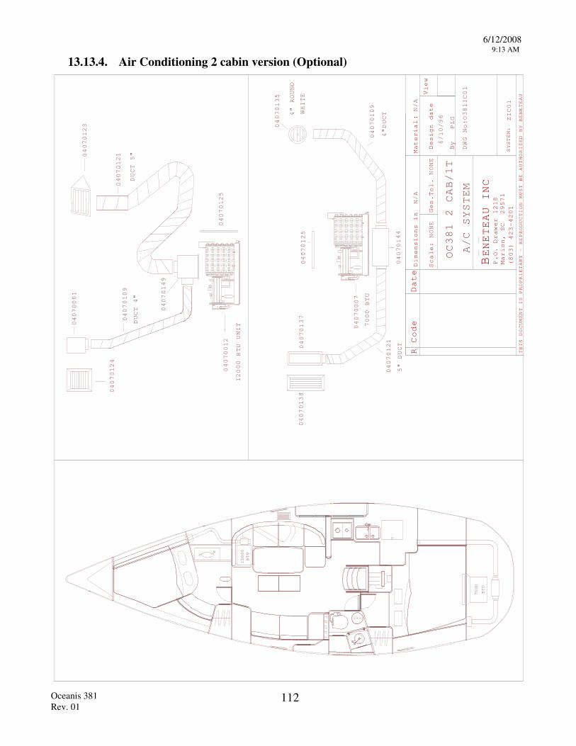
6/12/2008 9:13 AM
Oceanis 381 Rev. 01
112
13.13.4. Air Conditioning 2 cabin version (Optional)
R Code Date
Material
Scale:
Gen.
Design date
By
View
THIS DOCUMENT IS PROPRIETARY - REPRODUCTION
MUST BE AUTHORIZED BY BENETEAU
BENETEAU INC
P.O. Drawer 1218
Marion, SC 29571
(803) 423-4201
:
Dimensions in
Tol.
NONE
NONE
N/A
DWG No:
SYSTEM:
N/A
PLG ZIC01
040701
04070125
04070121
04070138
04070137
040701
O
OC A/C SYSTEM
381 2 CAB/1T
381IC01
6/10/96
12000
BTU
BTU
7000
04070135
04070007
09
4"DUCT
5" DUCT
7000 BTU
4" ROUND
WHITE
44
04070123
04070001
04070109
04070124
04070121
04070012
12000 BTU UNIT
04070125
DUCT 5"
DUCT 4"
04070149
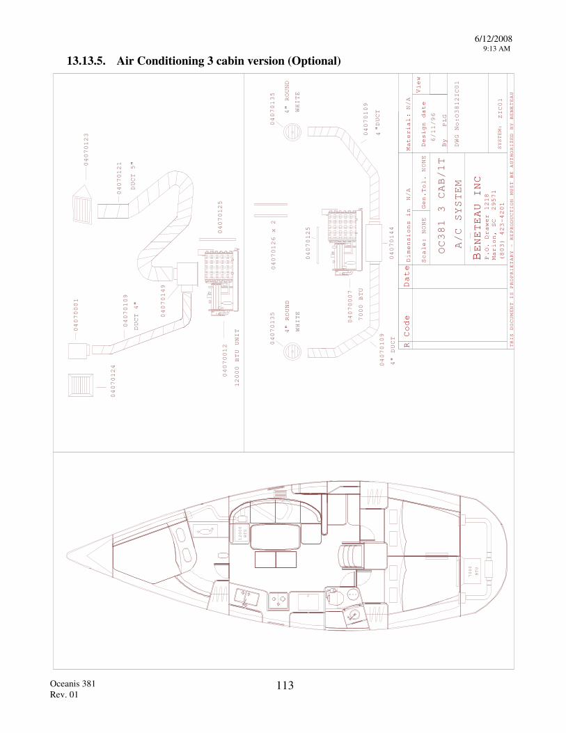
6/12/2008 9:13 AM
Oceanis 381 Rev. 01
113
13.13.5. Air Conditioning 3 cabin version (Optional)
R Code Date
Material
Scale:
Gen.
Design date
By
View
THIS DOCUMENT IS PROPRIETARY - REPRODUCTION
MUST BE AUTHORIZED BY BENETEAU
BENETEAU INC
P.O. Drawer 1218
Marion, SC 29571
(803) 423-4201
:
Dimensions in
Tol.
NONE
NONE
N/A
DWG No:
SYSTEM:
N/A
PLG ZIC01
04070
040701
040701
O
OC A/C SYSTEM
381
CAB/1T
38
6/1
/96
04070135
04070007
"DUCT
" DUCT
7000 BTU
4" ROUND
WHITE
04070135
4" ROUND
WHITE
09
4
109
4
4
31
12IC01
12000
BTU
BTU
7000
04070125
04070126 x 2
4
04070123
04070001
04070109
04070124
04070121
04070012
12000 BTU UNIT
04070125
DUCT 5"
DUCT 4"
04070149
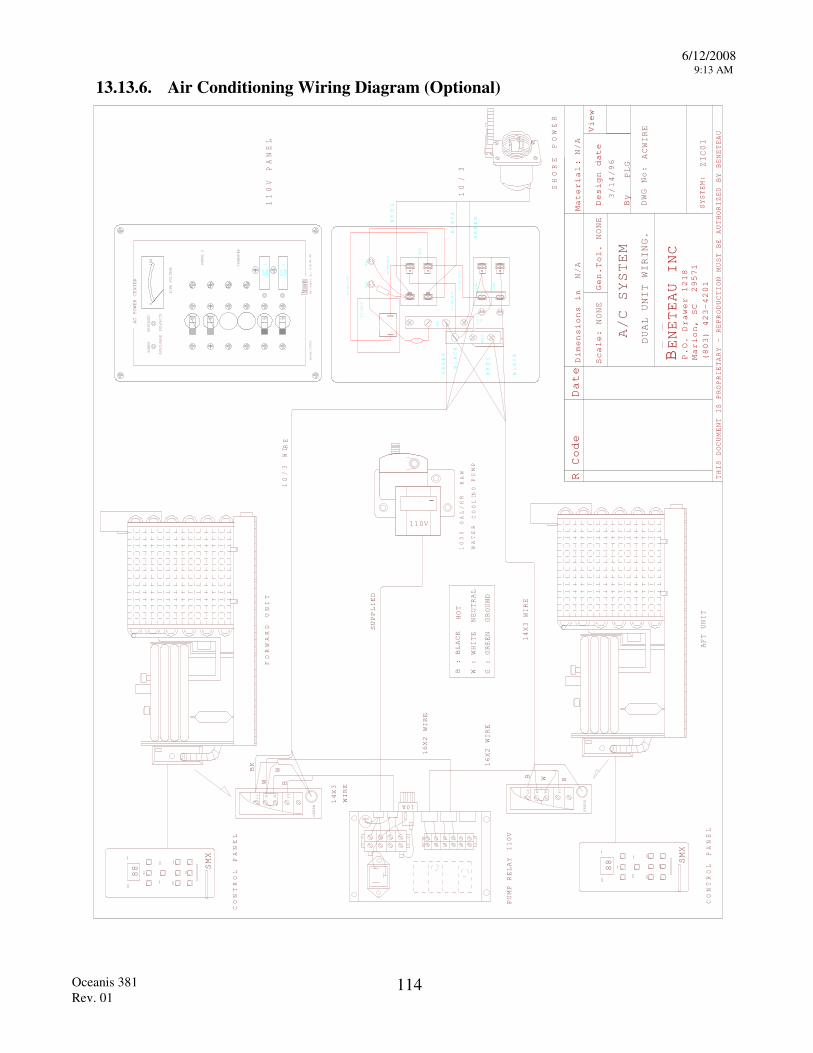
6/12/2008 9:13 AM
Oceanis 381 Rev. 01
114
13.13.6. Air Conditioning Wiring Diagram (Optional)
R Code Date
Material
Scale:
Gen.
Design date
By
View
THIS DOCUMENT IS PROPRIETARY - REPRODUCTION
MUST BE AUTHORIZED BY BENETEAU
BENETEAU INC
P.O. Drawer 1218
Marion, SC 29571
(803) 423-4201
:
Dimensions in
Tol.
NONE
NONE
N/A
DWG No:
SYSTEM:
N/A
PLG ZIC01
AC
88 SMX
CONTROL PANEL
110V AA/ C C RUS AIR PMP500
110V
L1 N P1
GREEN
N
WATER
GAL/HR
RAW
PUMP
COOLIN
G
1000
88 SMX
CONTROL PANEL
L1 N P1
GREEN
N
10A
GND
Bass Product
s, Inc., S
alem, MA,
USA
Beneteau 110
83106
0150
LINE VOLTAGE
REVERSED
POLARITY
AVAILABLE
POWER
SHORE 2
TRANSFER
AC POWER CENTER
OFF OFF OFF OFF
AIR
COND
1 2COND
AIR
25A
20A
GND
NEUT
MOV
+-
#10 AWG BL
ACK
#10 AWG WHITE
#18 AWG WHITE
#18 AWG BL
ACK
79-4405
13-0123
TYP
PL2
PL1
30A
110V PANEL
WHI T
E
GREEN
WHIT
E
BLACK
DUAL UNIT WIRING.
A/C SYSTEM
WIRE
3/14/96
SHORE POWER
10
/3
BLACK
GREEN
10/3 WI R
E
14X3 WIRE
SUPPLIED
16X2 WIRE
16X2 WIRE
14X3
WIRE
BK
BW
W
B W B
B : BLACK
HOT
W : WHITE NEUTRAL
G : GREEN GROUND
FORWARD UNIT
AFT UNIT
BLACK
PUMP RELAY
110V
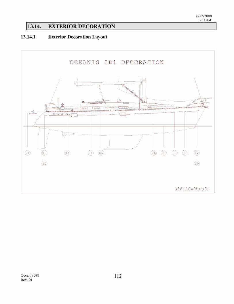
6/12/2008 9:14 AM
Oceanis 381 Rev. 01
112
13.14. EXTERIOR DECORATION
13.14.1 Exterior Decoration Layout
01 02 03 06 07 08 09 02
1010
OCEANIS 1 DECORATION
O 10000CSO01
38
38
BENETEAU OCEANIS 381
BENETEAU
BENETEAU
0504
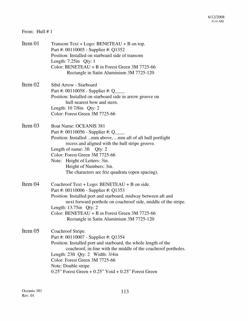
6/12/2008 9:14 AM
Oceanis 381 Rev. 01
113
From: Hull # 1 Item 01 Transom Text + Logo: BENETEAU + B on top. Part #: 00110005 - Supplier #: Q1352 Position: Installed on starboard side of transom Length: 7.25in Qty: 1 Color: BENETEAU + B in Forest Green 3M 7725-66 Rectangle in Satin Aluminium 3M 7725-120 Item 02 Stbd Arrow - Starboard Part #: 00110058 - Supplier #: Q____ Position: Installed on starboard side in arrow groove on hull nearest bow and stern. Length: 10 7/8in Qty: 2 Color: Forest Green 3M 7725-66 Item 03 Boat Name: OCEANIS 381 Part #: 00110056 - Supplier #: Q____ Position: Installed ...mm above, ...mm aft of aft hull portlight recess and aligned with the hull stripe groove. Length of name: 3ft Qty: 2 Color: Forest Green 3M 7725-66 Note: Height of Letters: 3in. Height of Numbers: 3in. The characters are friz quadrata (open spacing). Item 04 Coachroof Text + Logo: BENETEAU + B on side. Part #: 00110006 - Supplier #: Q1353 Position: Installed port and starboard, midway between aft and next forward porthole on coachroof side, middle of the stripe. Length: 13.75in Qty: 2 Color: BENETEAU + B in Forest Green 3M 7725-66 Rectangle in Satin Aluminium 3M 7725-120 Item 05 Coachroof Stripe. Part #: 00110007 - Supplier #: Q1354 Position: Installed port and starboard, the whole length of the coachroof, in-line with the middle of the coachroof portholes. Length: 23ft Qty: 2 Width: 3/4in Color: Forest Green 3M 7725-66 Note: Double stripe 0.25” Forest Green + 0.25” Void + 0.25” Forest Green

6/12/2008 9:14 AM
Oceanis 381 Rev. 01
114
Item 06 Boot Stripe Trim Line. Part #: 00110010 - Supplier #: Q1357 Position: Installed port and starboard, 1/2 inch above boot stripe. Length: 37ft Qty: 2 Width: 1/2in Color: Satin Aluminium 3M 7725-120 Item 07 Boot Stripe Paint: Interspray 800 YQB-663 Jade Green Part #: 01080663 Qty: 0.25 Gal Catalyst: Interspray 800 YQA-803 Part #: 01080803 Qty: 0.125 Pint Thinner: Interspray 800 YTA-820-01 Part #: 01080820 Qty: 0.125 Gal Position: As scribed on hull. Item 08 Hull Stripe Part #: 00110008 - Supplier #: Q1355 Position: Installed port and starboard in hull stripe groove. Length: 29ft Qty: 2 Width: 7/8in Color: Forest Green 3M 7725-66 Item 09 Text on Bow: BENETEAU Part #: 00110004 - Supplier #: Q1351 Position: Installed on port and starboard bow in hull stripe groove 4 1/2inches from start of hull stripe (excluding arrow). Length of name: 11” Qty: 2 Color: Forest Green 3M 7725-66 Note: Height of Letters: 3in. The characters are special type per sample. Item 10 Port Arrow - Port Part #: 00110057 - Supplier #: Q____ Position: Installed on port side in arrow groove on hull nearest bow and stern. Length: 10 7/8in Qty: 2 Color: Forest Green 3M 7725-66
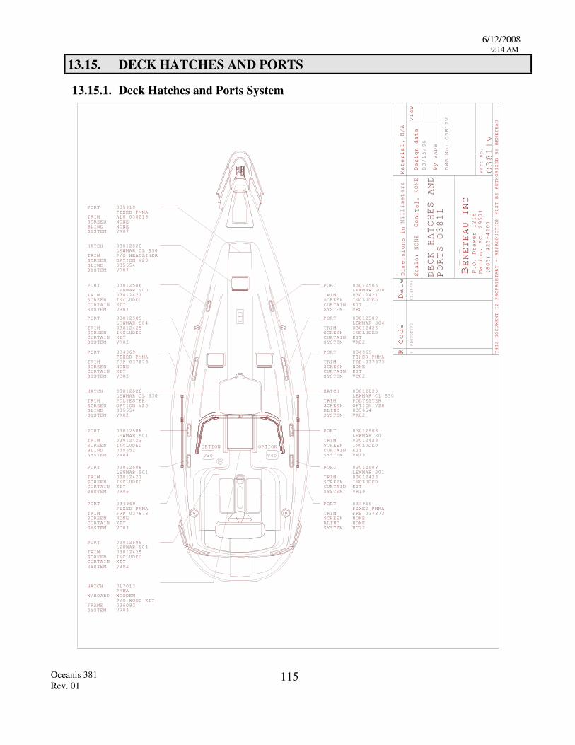
6/12/2008 9:14 AM
Oceanis 381 Rev. 01
115
13.15. DECK HATCHES AND PORTS
13.15.1. Deck Hatches and Ports System
TRIMSCREENBLINDSYSTEM VR07
PORT 035919FIXED PMMA
HATCH 03012020LEWMAR CL S30
TRIM SCREENBLIND 035654SYSTEM VR07
NONENONE
TRIMSCREEN
SYSTEM VR07
PORT 03012506LEWMAR S03012421INCLUDED
P/O HEADLINER
ALU 038018
HATCH 03012020LEWMAR CL S30
TRIM POLYESTERSCREENBLIND 035654SYSTEM VR0
TRIMSCREEN
SYSTEM
PORTFIXED PMMA
NONE
034969
FRP 037873
VC02
2
TRIMSCREEN
SYSTEM
PORT
VR02
03012509LEWMAR S03012425
04
00
INCLUDEDCURTAIN KIT
TRIMSCREENBLINDSYSTEM
PORT
VR
LEWMAR S003012508
103012423INCLUDED
04
TRIMSCREEN
SYSTEM
PORT
VR
LEWMAR S003012508
103012423INCLUDED
05
TRIMSCREEN
SYSTEM
PORTFIXED PMMA
NONE
034969
FRP 037873
VC03
R Code Date
Material
Scale:
Gen.
Design date
By
View
THIS DOCUMENT IS PROPRIETARY - REPRODUCTION
MUST BE AUTHORIZED BY BENETEAU
BENETEAU INC
P.O. Drawer 1218
Marion, SC 29571
(803) 423-4201
Part No.
:
Dimensions in
Tol.
Millimeters
NONE
NONE
N/A
BADB
DWG No:
0
03/15/96
DECK HATCHES
O381
PROTOTYPE
03/15/96
AND
PORTS O381
O381
V1
1V
TRIMSCREEN
SYSTEM
PORT 0301250LEWMAR S0301242INCLUDED
0
VB02
HATCH 017013PMMA
W/BOARD
FRAME 036093SYSTEM VR03
TRIMSCREEN
SYSTEM VR07
PORT 03012506LEWMAR S03012421INCLUDED
HATCH 03012020LEWMAR CL S30
TRIM POLYESTERSCREENBLIND 035654SYSTEM VR0
TRIMSCREEN
SYSTEM
PORTFIXED PMMA
NONE
034969
FRP 037873
VC02
2
TRIMSCREEN
SYSTEM
PORT
VR02
03012509LEWMAR S03012425
04
00
INCLUDEDCURTAIN KIT
TRIMSCREEN
SYSTEM
PORT
VR
LEWMAR S003012508
103012423INCLUDED
TRIMSCREEN
SYSTEM
PORT
VR
LEWMAR S003012508
103012423INCLUDED
TRIMSCREENBLINDSYSTEM
PORTFIXED PMMA
NONENONE
034969
FRP 037873
VC
19
19
22
OPTION V20
OPTION
V30
OPTION
V 04
OPTION V20 OPTION V20
94
5
CURTAIN KIT
CURTAIN KIT
CURTAIN KIT
1035652
CURTAIN KIT
WOODENP/O WOOD KIT
CURTAIN KIT
CURTAIN KIT
CURTAIN KIT
CURTAIN KIT
CURTAIN KIT
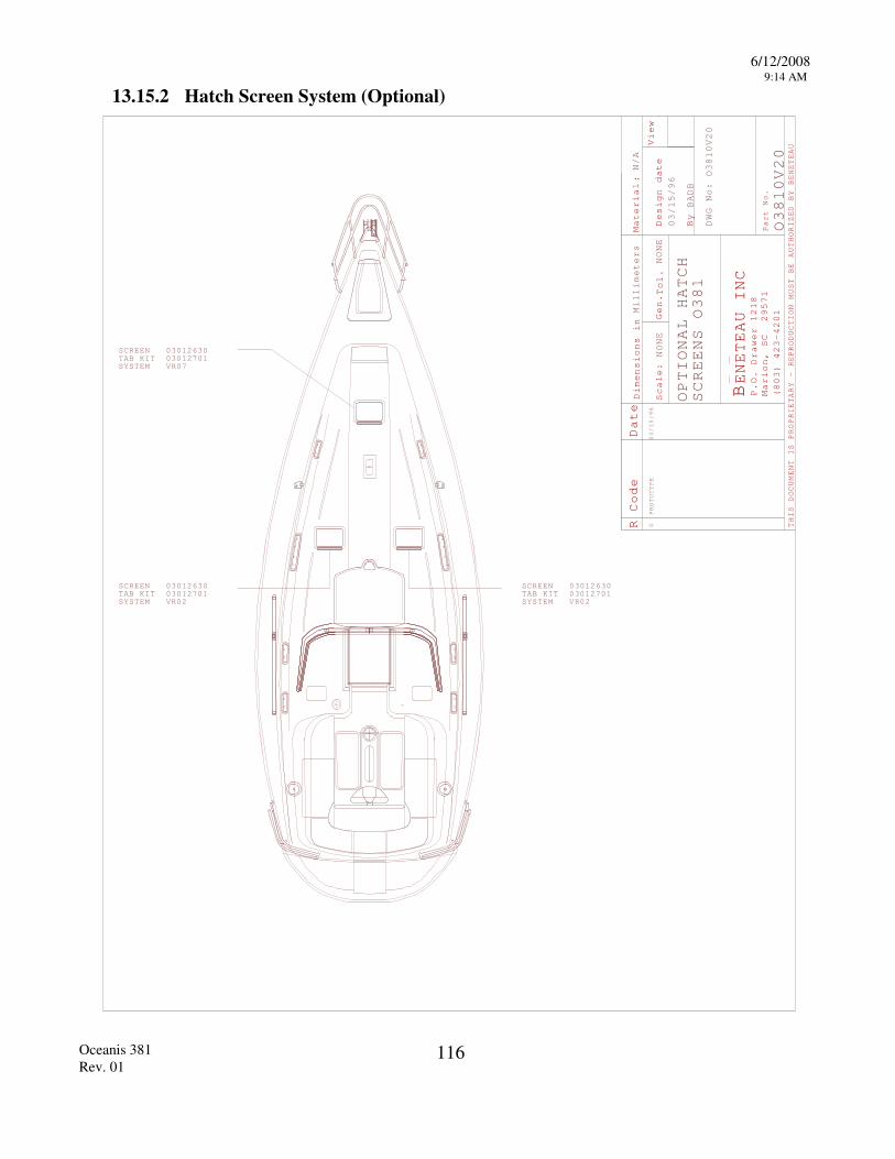
6/12/2008 9:14 AM
Oceanis 381 Rev. 01
116
13.15.2 Hatch Screen System (Optional)
R Code Date
Material
Scale:
Gen.
Design date
By
View
THIS DOCUMENT IS PROPRIETARY - REPRODUCTION
MUST BE AUTHORIZED BY BENETEAU
BENETEAU INC
P.O. Drawer 1218
Marion, SC 29571
(803) 423-4201
Part No.
:
Dimensions in
Tol.
Millimeters
NONE
NONE
N/A
BADB
DWG No:
0
03/15/96
PROTOTYPE
03/15/96
OPTIONAL HATCH
SCREENS O381
O3810V20
O3810V20
SCREEN 03012630TAB KIT 03012701
SCREEN 03012630TAB KIT 03012701
SCREEN 03012630TAB KIT 03012701
SYSTEM VR02
SYSTEM VR07
SYSTEM VR02
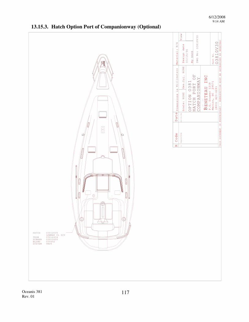
6/12/2008 9:14 AM
Oceanis 381 Rev. 01
117
13.15.3. Hatch Option Port of Companionway (Optional)
HATCH 030120LEWMAR CL S
TRIM SCREENBLINDSYSTEM
030124030126
VR05
R Code Date
Material
Scale:
Gen.
Design date
By
View
THIS DOCUMENT IS PROPRIETARY - REPRODUCTION
MUST BE AUTHORIZED BY BENETEAU
BENETEAU INC
P.O. Drawer 1218
Marion, SC 29571
(803) 423-4201
Part No.
:
Dimensions in
Tol.
Millimeters
NONE
NONE
N/A
BADB
DWG No:
0
03/15/96
O3810
PROTOTYPE
03/15/96
O3810V3
V30
OPTION
3
0COMPANIONWAY
HATCH PORT OF
O81
035652
3520
3420
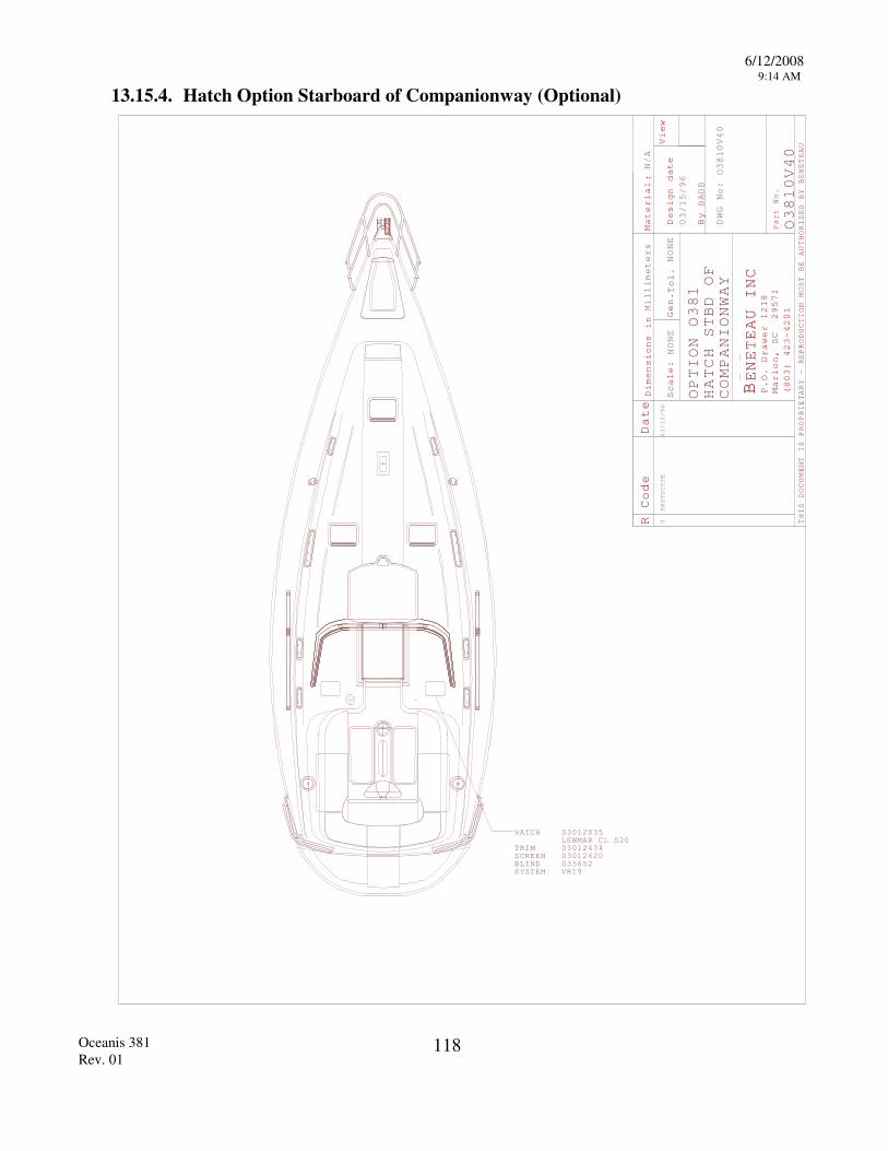
6/12/2008 9:14 AM
Oceanis 381 Rev. 01
118
13.15.4. Hatch Option Starboard of Companionway (Optional)
HATCH 030120LEWMAR CL S
TRIM SCREENBLINDSYSTEM
030124030126
VR19
R Code Date
Material
Scale:
Gen.
Design date
By
View
THIS DOCUMENT IS PROPRIETARY - REPRODUCTION
MUST BE AUTHORIZED BY BENETEAU
BENETEAU INC
P.O. Drawer 1218
Marion, SC 29571
(803) 423-4201
Part No.
:
Dimensions in
Tol.
Millimeters
NONE
NONE
N/A
BADB
DWG No:
0
03/15/96
O3810
PROTOTYPE
03/15/96
O3810V
OPTION O381
4
V40
HATCH STBD OF
COMPANIONWAY
0
035652
3520
3420
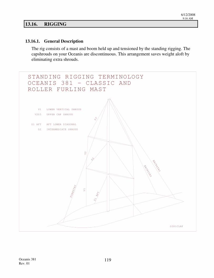
6/12/2008 9:16 AM
Oceanis 381 Rev. 01
119
13.16. RIGGING
13.16.1. General Description The rig consists of a mast and boom held up and tensioned by the standing rigging. The capshrouds on your Oceanis are discontinuous. This arrangement saves weight aloft by eliminating extra shrouds.
V1
V2
D3
V2D3
D1 AFT
D1 AFT
D2
D2
STANDING RIGGING TERMINOLOGYFORESTAY
BACKSTAY
BACKSTAY
OCEANIS 1 - CLASSIC ANDROLLER FURLING MAST
1CLRF
38
UPPER CAP SHROUD
LOWER VERTICAL SHROUD
AFT LOWER DIAGONAL
INTERMEDIATE SHROUD
V1
O38
6/12/2008 9:16 AM
Oceanis 381 Rev. 01
120
13.16.2. Tuning
TUNING A MASTHEAD RIG
!!!! WARNING
Before un-hooking the mast from the crane used to step the mast, for safety, make sure that the minimum amount of thread of the turnbuckle is engaged. Ensure that at least 1-1/2 times the thread diameter is engaged or that the holes for the split pins are visible through the turnbuckle body - this is refered to as the minimum safety position of a turnbuckle. When making any adjustments to the mast, always make sure that the mast is straight and that there is no lateral or sideways bend. Fore and aft pre-bend is acceptable but must never exceed half the fore and aft dimension of the mast section. If, at any step, you are having difficulty keeping the mast straight you have probably over tensioned the stays and shrouds causing excess compression loads on the unsupported mast panels between the stays and shrouds. Reverse the steps and re-tension the stays and shrouds using fewer turns. Always make sure that all turnbuckles are clean and properly lubricated with a non-graphite grease. When adjusting a turnbuckle, it is best to make less than three turns of the turnbuckle before adjusting the opposite turnbuckle. • Set the rake of the mast by adjusting the forestay to the pre-determined length according to the
standing rigging specification sheet. TIP: Set the forestay to the correct measurement before installing it on the mast and note the distance between the threaded stud and the turnbuckle body. After stepping the mast you will be able to know the forestay length by comparing this measurement.
• Make sure the intermediates (D2) are released to their minimum safety position. • Center the mast athwartships, using the capshroud (V1) turnbuckles. TIP: Using two pieces of
rigging tape, mark the port and starboard toe rails (opposite the mast) at an equal distance from the forestay. Use a tape measure hoisted on the jib halyard (it does not need to be hoisted all the way) to check the port and starboard measurements at the toe rail rigging tape mark. They must be the same. When taking these measurements, ensure that you are taking a straight line measurement from the jib halyard sheave to the toe rail mark and that no equipment is fouling the measuring tape overhead.
• Tension both backstays equally. This will introduce pre-bend in the mast and make it easier to tension
the cap shrouds. • Tension the cap shrouds (V1) an equal number of turns on port and starboard. Do not allow the
intermediates (D2) to become tight. At this stage you will have more pre-bend than is required.
6/12/2008 9:16 AM
Oceanis 381 Rev. 01
121
• Release the backstays equally until they are slack or to their minimum safety position. • Tension the lower shrouds (D1) so as to remove the excess pre-bend. Make sure that the mast remains
straight athwartships (make sure there is no lateral/sideways bend). • Tension both backstays equally. TIP: Compare the distance between the threaded studs of each
turnbuckle. • Tension the intermediates and ensure a straight mast athwartship. Very little tension is required on
the intermediates. • The mast should now be perfectly straight athwartship and fore and aft. • Lock all turnbuckles with split pins. • Test sail the boat in 15 knots of wind with the boat heeled hard on the wind the mast must remain
straight on both port and starboard tack. Adjust the rigging as necessary so that the mast will be straight on both tacks in these conditions.
6/12/2008 9:16 AM
Oceanis 381 Rev. 01
122
13.16.3. Roller Furling Mast Mainsail Installation
MAINSAIL INSTALLATION 1. The main should be installed in as little wind as possible. 2. Be sure the furling drum line is completely wound with line before installing the mainsail. (Wind the drum by hand to wrap more line onto the drum.) 3. Lower the main swivel hoist car to the gooseneck with the main halyard. 4. Attach the mainsail headboard to the shackle on the bottom of the swivel car. 5. Hoist the mainsail slowly, feeding the luff tape into the extrusion luff groove. 6. Attach the mainsail tack to the lower swivel shackle and tension the luff with a winch. 7. Run the out haul line thru the block on the clew of the main and back to the out haul car. 8. The main is now ready to be furled. 9. When sail is out, there should be no less than 2 wraps and no more than 4 wraps.
13.16.4 Roller Furling Mast Operation
FURLING MAST OPERATION 1. Two lines control the mainsail furling operation: The furling line controls the rotation of the furling tubes and the out haul line controls the tension on the sail. 2. NOTE: IT IS IMPORTANT TO REMEMBER THAT THE FURLING LINE CONTROLS THE SAIL AREA AND THE OUT HAUL LINE CONTROLS THE SAIL SHAPE! 3. Always furl and unfurl the main with the boat head up to wind. 4. The main is unfurled by easing out the furling line while taking up on the mainsail out- haul. 5. The main is furled by taking in on the main inhaul line, it is important to feed the out haul line as you furl the main. 6. NOTE: NEVER TAKE IN ONE LINE WITHOUT KEEPING A LITTLE TENSION ON THE OPPOSITE LINE! 7. The main may be reefed by turning the boat into the wind and furling the main up to the marked reef points on the sail.
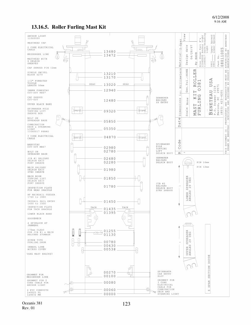
6/12/2008 9:16 AM
Oceanis 381 Rev. 01
123
13.16.5. Roller Furling Mast Kit
ANCHOR LIGHT11060000
Z SPAR SECTION Z
00E
00000
R Code Date
Material
Scale
Gen.
Design date
By
View
BENETEAU USA
P.O. Drawer 1218
Marion, SC 29571
(803) 423-4201
Part No.
D:
imensions in:
Millimeters
None
Tol.:NONE
Z-
rSpa
BADB
Also Shown Part #'s
11060000
Anchor Light
110600
Deck/Steaming
Light
0801
Upper Spread
0801
Lower
Spread
1
0
- DRAWN BY BENETEAU - SPECIFIED AND DESIGNED BY PRODUCT MANUFACTURER
THIS DOCUMENT IS - PROPRIETARY AND REPRODUCTIO
MUST BE AUTHORIZED BY BENETEAU
N
6
2 PVC CONDUITS1x1x
PIN
PIN
ANGLED
DEG
LOWER SPREADER
mm
mm
16
12
20
ANGLED
DEG
UPPER SPREADER
20
0
HALYARDGENNEKER
0
0
0
GENNEKHALYARD
ER
0
0
0
TACK TACK
0
00
0
0
HEAD HEAD
0
45
MAST KIT ROLLER
FURLING O381
7
____
____
" FORESTAYTOGGLE
INNER FORESTAYCUT-OUT
CAP SHROUDCUT-OUT
UPPER BLACK BAND
RBS7
LENGTH mm
MASTHEAD CAP
2 CORE ELECTRICALCABLE
MESSENGER LINE
MASTHEAD WITH
SHEAVESDELRIN
1/2
CAP SHROUD PIN mm12
SINGLE SWIVELBLOCK Z
COMBINATIONDECK & STEAMINGLIGHT110600 PERKO
3 CORE ELECTRICALCABLE
1
BOLT ONSPREADER BASE
SPINNAKER POLETOPPING LIFTSHEAVE BOX
7
OD25 SLOD32 MH
INSPECTION PLATEFOR TACK SHACKLE
LOWER BLACK BAND
GOOSENECK
TRYSAIL SAIL ENTRY to
2 SPINLOCK XTJAMMERS
170mm CLEATFOR JIB #1 & MAIN
FURLING DRUM
HALYARD STOWAGE
SCREW TYPE
INHAUL LINEACCESS COVER
VANG MAST BRACKET
SS ENTRY
DELRIN EXIT
BABYSTAYCUT-OUT RBS
JIB #1
PORT
MAIN
SHEAVE
SHEAVE
BOLT ONSPREADER BASE
STBD
HALYARDDELRIN EXIT
HALYARDDELRIN EXIT
6
279
50
7
+35+70
0
0
0
0
0
0JIB #2HALYARDDELRINSTBD SHEAVE
EXIT
SPINNAKERPOLETOPPINGLIFTDELRIN EXIT
MAIN BOOM TOPPING LIFT
PORT SHEAVEDELRIN EXIT
INSPECTION PLATEFOR HEAD SHACKLE
RF MAINSAIL FEEDER to
053806300780
11301255
13951435
145
1780
1850
1980
22802480
27802980
4870
5350
5850
09320
12480
12940
13020
1317013210
1 47213480
1760 1880
1450 1500
04/28/97
08011
GROMMET FOR3 COREELECTRICALCABLE FORCOMBINATIONDECK ANDSTEAMING LIGHT
00080
00060
GROMMET FORMESSENGER LINE
GROMMET FOR 2CORE CABLE FOR ANCHOR LIGHT
00 00100270 SPINNAKER
CAR ENTRYSLOT
005
3
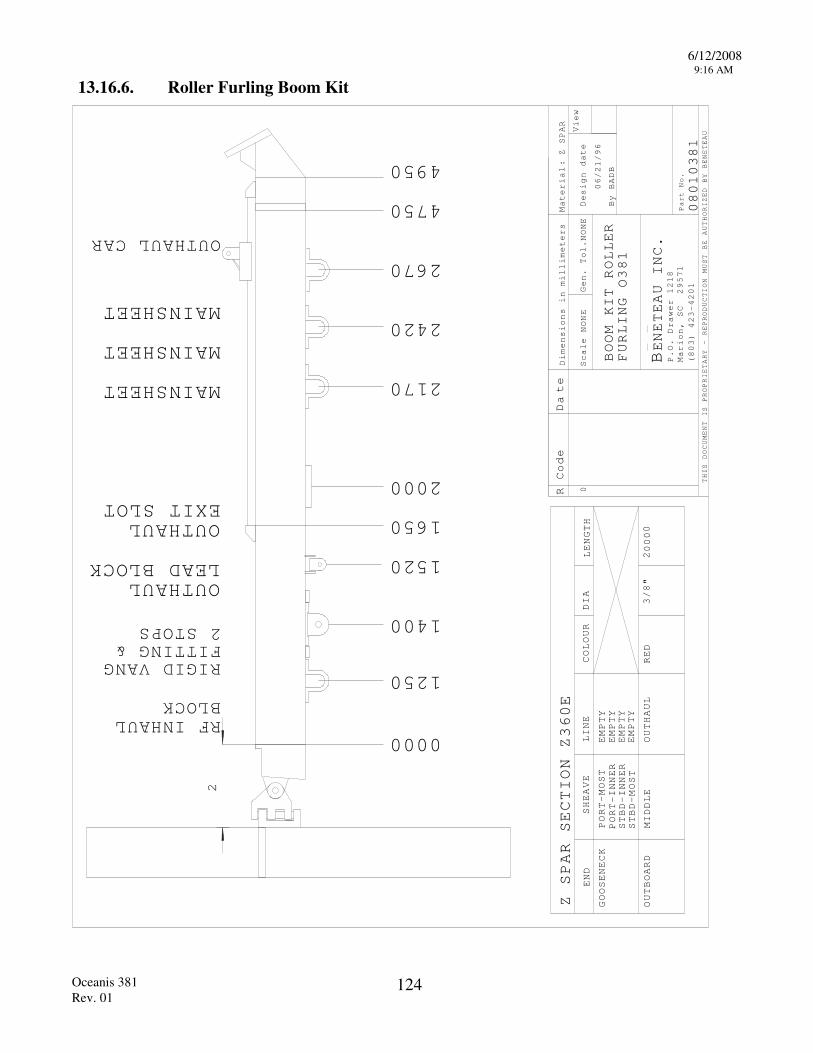
6/12/2008 9:16 AM
Oceanis 381 Rev. 01
124
13.16.6. Roller Furling Boom Kit
R Code D
te
Material
Scale
Gen. Tol.
Design date
By
View
THIS DOCUMENT IS PROPRIETARY - REPRODUCTION
MUST BE AUTHORIZED BY BENETEAU
BENETEAU INC
P.O. Drawer 1218
Marion, SC 29571
(803) 423-4201
Part No.
Dimensions i
:n
.
a
0000
OUTHAUL CAR
Z SPAR SECTION Z
GOOSENECK
OUTBOARD
END
PORT-MOST
PORT-INNER
STBD-INNER
STBD-MOST
SHEAVE
LINE
COLOUR
DIA
0
millimeters
BADB
E
BOOM KIT ROLLER
FURLING
EMPTY
LENGTH
EMPTY
EMPTY
EMPTY
Z SPAR
2
RIGID VANGFITTING & STOP
RF INHAULBLOCK
OUTHAUL
EXIT SLOT
OUTHAULLEAD BLOCK
MAINSHEET
MAINSHEET
MAINSHEET
NONE
NONE
MIDDLE
OUTHAUL
RED
3/8"
20
06/
/96
1250
2S
00
21
360
08010381
O381
1400
2000
2170
2420
2670
4750
4950
0 1520
1650
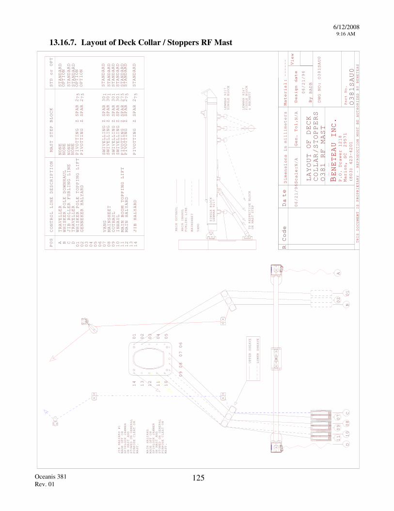
6/12/2008 9:16 AM
Oceanis 381 Rev. 01
125
13.16.7. Layout of Deck Collar / Stoppers RF Mast
R Code D
te
Material
Scale
Gen. Tol.
Design date
By
View
THIS DOCUMENT IS PROPRIETARY - REPRODUCTION
MUST BE AUTHORIZED BY BENETEAU
BENETEAU INC
P.O. Drawer 1218
Marion, SC 29571
(803) 423-4201
Part No.
Dimensions i
:n
.
amillimeters
:N/A
BADB
N/A
LAYOUT
COLLAR/STOPPERS
OF DECK
------
MAST
DWG NO:
SAU0
RF
TO
ON MAST STEP
MAIN INHAUL
FURLING LINE
MAINSHEET
VANG
RESPECTIVE BLOCK
MAIN OUTHAUL
SINGLE BLOCK
LEWMAR 9217
LEWMAR 9217
SINGLE BLOCK
LEWMAR 9
67
FIDDLE BLOCK
& BECKETT
CONTROL LINE DESCRIPTION
MAST STEP BLOCK
STD or OPT
POS
NONE
STANDARD
0 0 0
STANDARD
STANDARD
NONE
STANDARD
A B C
D
01
02
03 4 5 6 7
0 08
09
10
11
12
13
14
TRAVELLER
WHISKER POLE DOWNHAUL
JIB ROLLER FURLING LINE
TRAVELLER
WHISKER POLE TOPPING LIFT
GENNEKER HALYARD
JIB HALYARD
NONE
SWIVELLING Z SPAR 30
PIVOTTING Z SPAR 2
NONE
PIVOTTING Z SPAR 2
SWIVELLING Z SPAR 30
PIVOTTING Z SPAR 2
PIVOTTING Z SPAR 2
OPTION
OPTION
OPTION
STANDARD
STANDARD
STANDARD
SAU0
MAIN BOOM TOPPING LIFT
PIVOTTING Z SPAR 2
STANDARD
MAIN HALYARD
JIB HALYARD #1
SPINLOCK JAMMER
ON MAST
MADE OFF ON
AND
STOWED ON GENERAL
PURPOSE CLEAT ON
MAST.
07
06
09
08
13
14
12
11
10
01
00002 3 4 5
SPINLOCK JAMMER
ON MAST
MADE OFF ON
AND
STOWED ON GENERAL
PURPOSE CLEAT ON
MAST.
MAIN HALYARD
UPPER SHEAVE
LOWER SHEAVE
0
08
11
907
10
01
02
A
BC
06/21/96
06/21/96
O381
O381
O381
D
75
75 1 1
75
75
75
VANG
MAINSHEET
OUTHAUL
INHAUL
SWIVELLING Z SPAR 301
SWIVELLING
Z SPAR
301
STANDARD
STANDARD
2
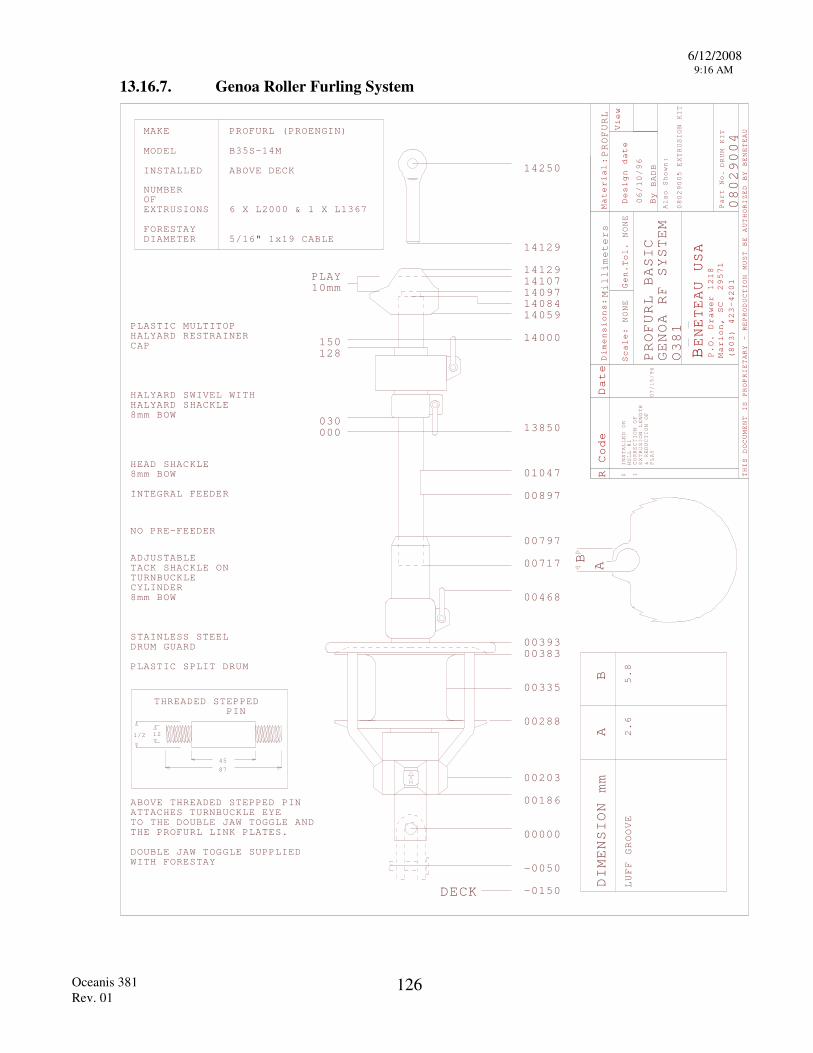
6/12/2008 9:16 AM
Oceanis 381 Rev. 01
126
13.16.7. Genoa Roller Furling System
R Code Date
Material
Scale
Gen.
Design date
By
View
THIS DOCUMENT IS PROPRIETARY - REPRODUCTION
MUST BE AUTHORIZED BY BENETEAU
BENETEAU USA
P.O. Drawer 1218
Marion, SC 29571
(803) 423-4201
Part No.
:
:
Dimensions:
NONE
0
Tol. NONE
BADB
HALYARD SWIVEL
PLASTIC MULTITOP HALYARD RESTRAINERCAP
MAKE
MODEL
PROFURL (PROENGIN)
INSTALLED DECK
NUMBEROFEXTRUSIONS X L2000 & 1 X L
FORESTAYDIAMETER
WITH
HEAD SHACKLE
DIMENSION
AB
LUFF GROOVE
2.6
5.8
mm
FURL
PRO
Also Shown:
EXTRUSION KIT
Millimeters
PROFURL
DRUM KIT
HALYARD SHACKLEmm BOW
mm BOW
NO PRE-FEEDER
0802
BASIC
GENOA RF SYSTEM
O
00003
0
000
M
" 1x19 CABLE
TACK
STAINLESS STEEL
PLASTIC
SHACKLE ON
mm
DRUM GUARD
ADJUSTABLE
TURNBUCKLECYLINDER
BOW
SPLIT DRUM
ABOVE
AB
STEPPED PIN
1
5
THREADED
THREADED STEPPED PIN
-
-00
00
DECK
00
00
00
00
00
0
ABOVE
ATTACHES TURNBUCKLE EYE TO THE DOUBLE JAW TOGGLE ANDTHE PROFURL LINK PLATES.
DOUBLE JAW TOGGLE SUPPLIEDWITH FORESTAY
INTEGRAL FEEDER
/16
15128
08
8
8
2
4
87
00
00300
002
001
900
mmPLAY0
381
06/10/96
08029005
4
B35S-14
6 13
514129
14250
1/2
0150
50
86
203
88
335
38393
4
7
10
1412914107140 7140 414059
14000
13850
68
17
797
897
47
67
1 98
INSTALLED ON
HULL #1
1 CORRECTION OF
EXTRUSION LENGTH
& REDUCTION OF
PLAY
07/15/96
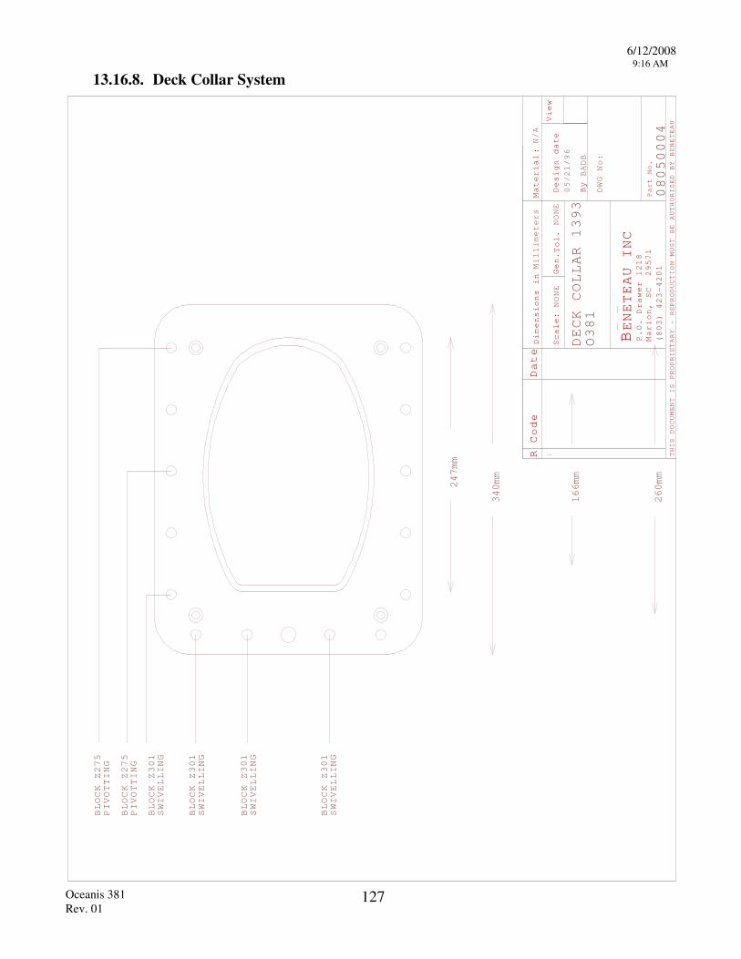
6/12/2008 9:16 AM
Oceanis 381 Rev. 01
127
13.16.8. Deck Collar System
R Code Date
Material
Scale:
Gen.
Design date
By
View
THIS DOCUMENT IS PROPRIETARY - REPRODUCTION
MUST BE AUTHORIZED BY BENETEAU
BENETEAU INC
P.O. Drawer 1218
Marion, SC 29571
(803) 423-4201
Part No.
:
Dimensions in
Tol.
Millimeters
NONE
NONE
N/A
BADB
DWG No:
1
05/21/96
O381
DECK COLLAR 1393
08050004
166mm
260mm
247mm
340mm
BLOCK Z275
PIVOTTING
BLOCK Z275
PIVOTTING
BLOCK Z301
SWIVELLING
BLOCK Z301
SWIVELLING
BLOCK Z301
SWIVELLING
BLOCK Z301
SWIVELLING
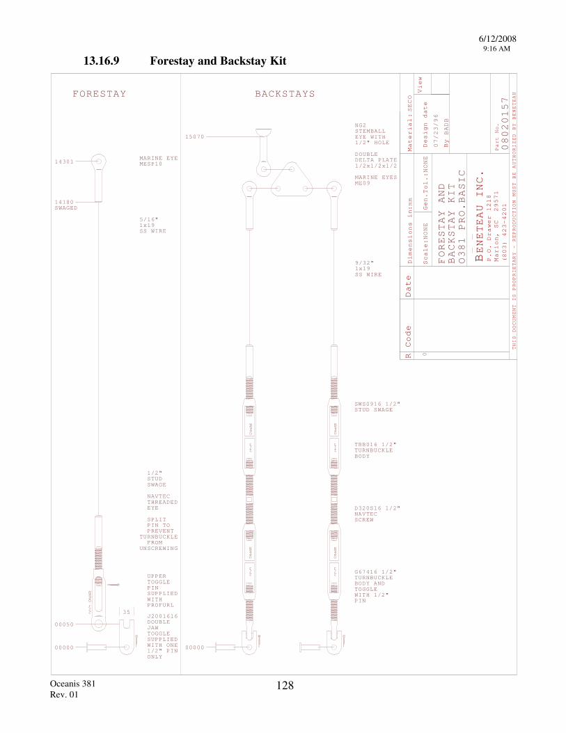
6/12/2008 9:16 AM
Oceanis 381 Rev. 01
128
13.16.9 Forestay and Backstay Kit
R Code
Material
Scale
Gen.
Design date
By
View
THIS DOCUMENT IS PROPRIETARY - REPRODUCTION
MUST BE AUTHORIZED BY BENETEAU
BENETEAU INC
P.O. Drawer 1218
Marion, SC 29571
(803) 423-4201
Part No.
Dimensions i
:n
.
Date
:
:
NONE
Tol.:
NONE
BADB
SECO
mm
0
080201
00000
1x19SS WIRE
FORES
2/3
OPEN
2/3
OPEN
2/3
OPEN
2/3
OPEN
PINSUPPLWITHPROFU
UPPERTOGGL
SWS 16STUD SW
TBB016TURNBUCBODY
D320S16NAVTEC SCREW
G67416TURNBUCBODY ANTOGGLEWITH PIN
00000
IED
RL
E
"
"AGE
KLE
KLED
1/2"
1/2
1/2
1/2"
SWAGED
TAY
2/3
OPEN
NAVTECTHREADEDEYE
SPLIT PIN TOPREVENT
TURNBUCKLEFROM
UNSCREWING
JAWTOGGLSUPPLWITH
"ONLY
E
IED
PINONE
DOUBLE
5
/16"
STEMBALL
BACKSTAYS
FORESTAY AND
BACKSTAY KIT
5
000
1/2"
PRO.BASIC
7
07/23/96
O381
14301MARINE EYEMESP10
5
14180
50
3J2001616
1/2
"STUDSWAGE
1/2
NG2
EYE WITH1/2" HOLE
DOUBLE DELTA PLATE1/2x1/2x1/2
MARINE EYESME09
" 1x19SS WIRE
15070
9/32
09
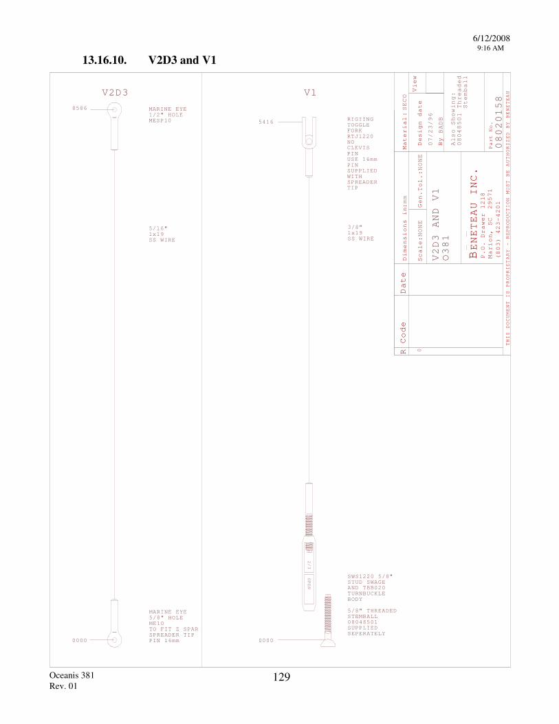
6/12/2008 9:16 AM
Oceanis 381 Rev. 01
129
13.16.10. V2D3 and V1
R Code
Material
Scale
Gen.
Design date
By
View
THIS DOCUMENT IS PROPRIETARY - REPRODUCTION
MUST BE AUTHORIZED BY BENETEAU
BENETEAU INC
P.O. Drawer 1218
Marion, SC 29571
(803) 423-4201
Part No.
Dimensions i
:n
.
Date
:
:
NONE
Tol.:
NONE
BADB
SECO
mm
A S
:0804850
lso
howing
Threaded
Stemball
2V D3
0000
2/3
OPEN
0000
V1
SWSSTUD SWANDTURNBUCBODY
TBB
" THSTEMBAL0804850SUPPLIESEPERAT
D
"AGE
KLE02
READEL
D ELY
0
0802015MARINE EYE
" HOLE
1x19SS WIRE
1x19SS WIRE
V2D3 AND
V1
85861/2MESP10
5/16"
RIGIINGTOGGLEFORKRTJ
CLEVISPIN
NO
USE 16mmPINSUPPLIEDWITHSPREADERTIP
1220
5416
MARINE EYE5/8" HOLEME10TO FIT Z SPAR SPREADER TIPPIN 16mm
3/8"
5/81220
0
5/8
1
O381
07/23/96 1
8
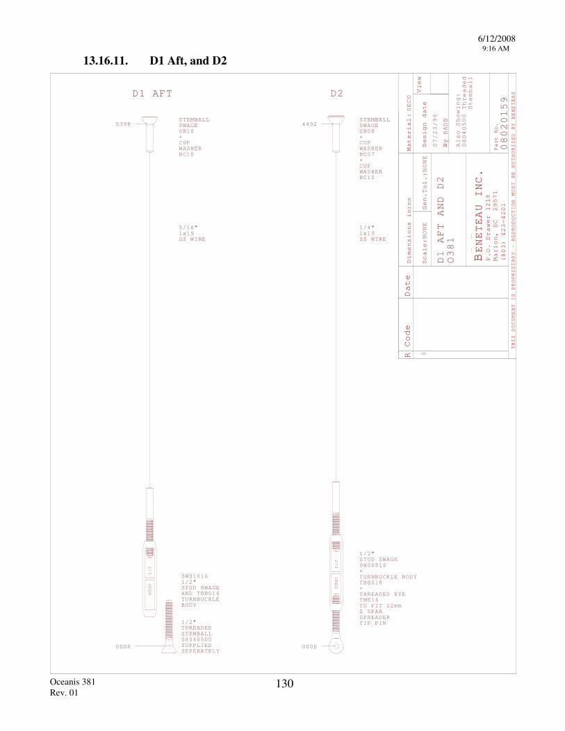
6/12/2008 9:16 AM
Oceanis 381 Rev. 01
130
13.16.11. D1 Aft, and D2
R Code
Material
Scale
Gen.
Design date
By
View
THIS DOCUMENT IS PROPRIETARY - REPRODUCTION
MUST BE AUTHORIZED BY BENETEAU
BENETEAU INC
P.O. Drawer 1218
Marion, SC 29571
(803) 423-4201
Part No.
Dimensions i
:n
.
Date
:
:
NONE
Tol.:
NONE
BADB
SECO
mm
A S
:0804
lso
howing
Threaded
Stemball
500
00
STEMBALLSWAGE
2/3
OPEN
D2
0
080201
00
5
SB0+
SHERBC07+CUP
1x19SS WIRE
WASHERBC10
0
1/2"STUD SWAGESWS0 16+TURNBUCKLE BODYTBB016+THREADED EYETME16TO FIT 12mmZ SPARSPREADERTIP PIN
D1 AFT AND D2
O381
07/23/96
2/3
OPEN
0000
STUD SWAGEANDTURNBUCKLEBODY
TBB0
"SWS
STEMBALL0804SUPPLIED SEPERATELY
THREADED"
D1 AFT
STEMBALLSWAGESB+
WASHERCUP
BC
1x19SS WIRE
/16"
10
1
539810
5
0161/2
16
1/2
0500
44928
WACUP
1/4"
8
9
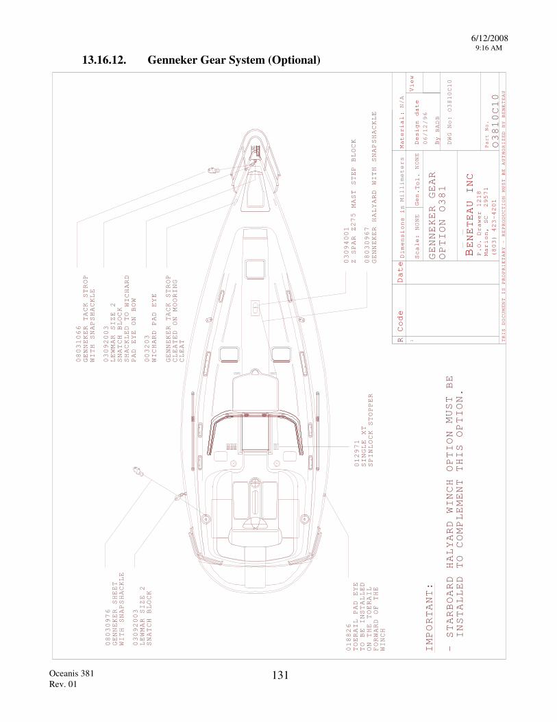
6/12/2008 9:16 AM
Oceanis 381 Rev. 01
131
13.16.12. Genneker Gear System (Optional)
R Code Date
Material
Scale:
Gen.
Design date
By
View
THIS DOCUMENT IS PROPRIETARY - REPRODUCTION
MUST BE AUTHORIZED BY BENETEAU
BENETEAU INC
P.O. Drawer 1218
Marion, SC 29571
(803) 423-4201
Part No.
:
Dimensions in
Tol.
Millimeters
NONE
NONE
N/A
BADB
DWG No:
1
GENNEKER TACK STROP
WITH SNAPSHACKLE
030920
LEWMAR SIZE
SNATCH BLOCK
SHACKLED TO
GENNEKER SHEET
WITH SNAPSHACKLE
LEWMAR SIZE
SNATCH BLOCK
Z SPAR Z
MAST STEP BLOCK
GENNEKER HALYARD WITH SNAPSHACKLE
08030976
03092003
2
08031066
03
2 WICHARD
PAD EYE ON BOW
GENNEKER TACK STROP
CLEATED ON MOORING
CLEAT
WICHARD PAD EYE
003203
03094001275
08030967
018826
TOERAIL PAD EYE
TO BE INSTALLED
ON THE TOERAIL
FORWARD OF THE
WINCH
012971
SINGLE X
SPINLOCK TSTOPPER
GENNEKER GEAR
OPTION O381
06/12/96
O3810C10
O3810C10
IMPORTANT:
- STARBOARD HALYARD WINCH OPTION
BE
INSTALLED TO COMPLEMENT THIS OPTION.
MUST
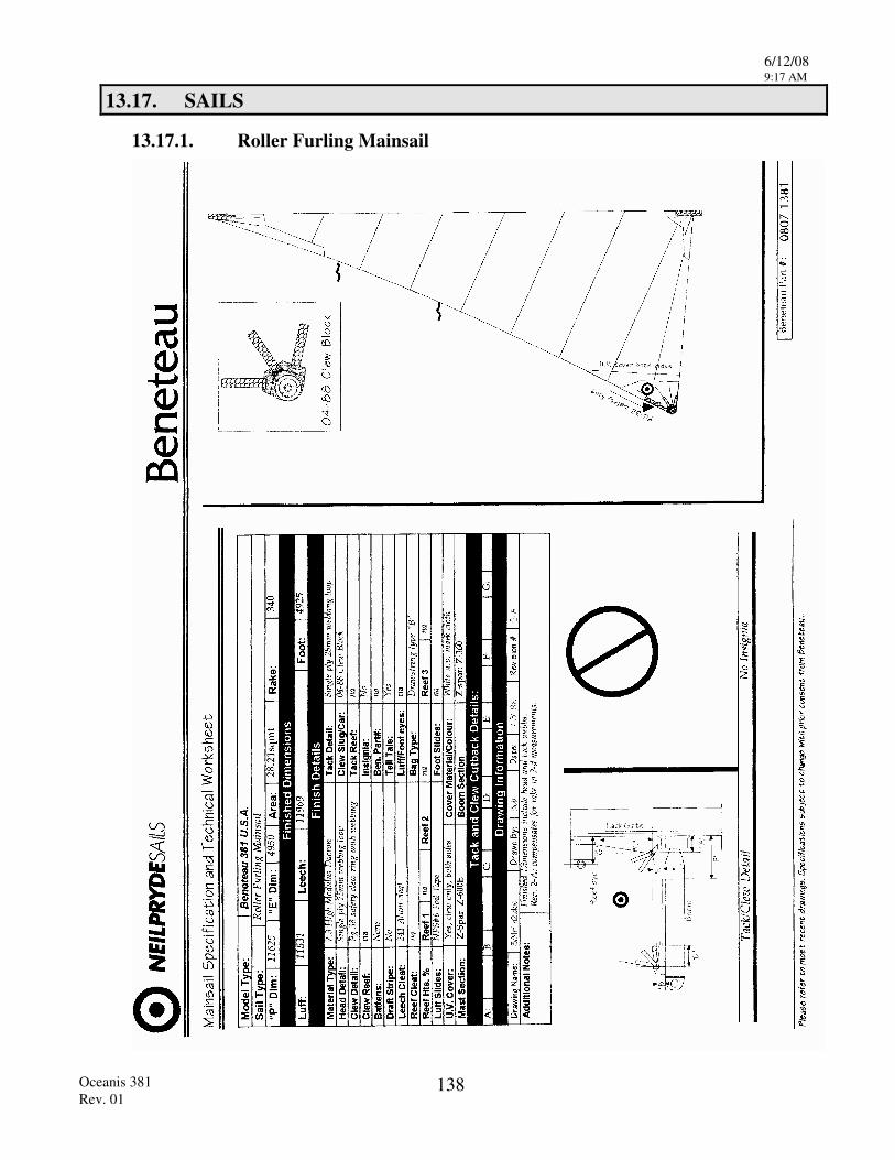
6/12/08 9:17 AM
Oceanis 381 Rev. 01
138
13.17. SAILS
13.17.1. Roller Furling Mainsail
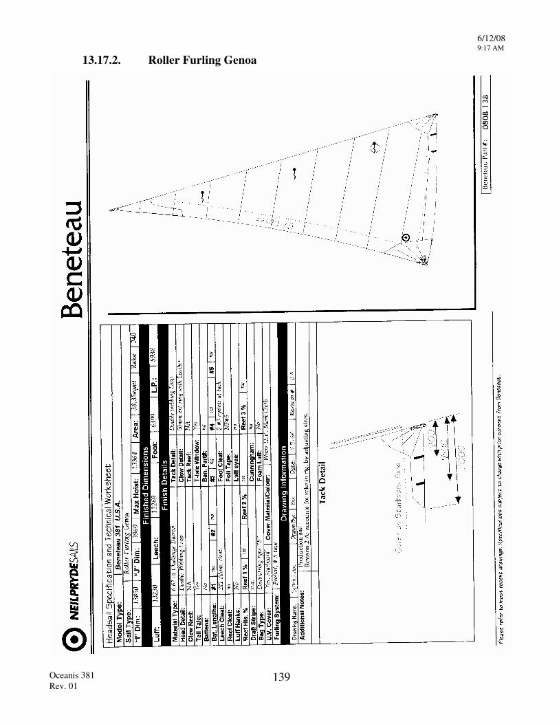
6/12/08 9:17 AM
Oceanis 381 Rev. 01
139
13.17.2. Roller Furling Genoa

Appendix 1
OCEANIS 381
Appendix A
Modification Updates
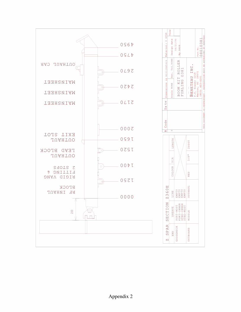
Appendix 2
R Code D
te
Material
Scale
Gen. Tol.
Design date
By
View
THIS DOCUMENT IS PROPRIETARY - REPRODUCTION
MUST BE AUTHORIZED BY BENETEAU
BENETEAU INC
P.O. Drawer 1218
Marion, SC 29571
(803) 423-4201
Part No.
Dimensions i
:n
.
a
0000
OUTHAUL CAR
Z SPAR SECTION Z
GOOSENECK
OUTBOARD
END
PORT-MOST
PORT-INNER
STBD-INNER
STBD-MOST
SHEAVE
LINE
COLOUR
DIA
0
millimeters
BADB
E
BOOM KIT ROLLER
FURLING
EMPTY
LENGTH
EMPTY
EMPTY
EMPTY
Z SPAR
200
RIGID VANGFITTING & STOP
RF INHAULBLOCK
OUTHAUL
EXIT SLOT
OUTHAULLEAD BLOCK
MAINSHEET
MAINSHEET
MAINSHEET
NONE
NONE
MIDDLE
OUTHAUL
RED
3/8"
20
06/
/96
1250
2S
00
21
360
08010381
O381
1400
2000
2170
2420
2670
4750
4950
0
1520
1650
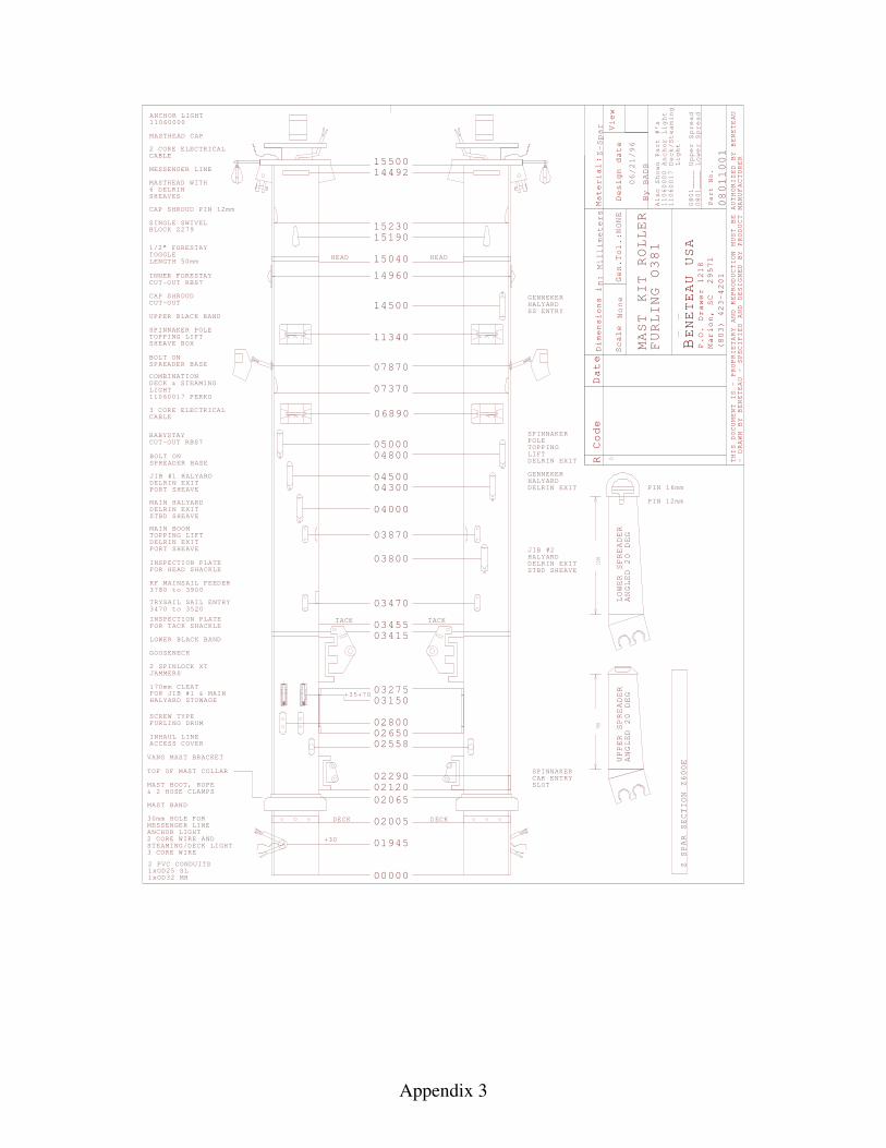
Appendix 3
ANCHOR LIGHT11060000
Z SPAR SECTION Z
00E
00000
R Code Date
Material
Scale
Gen.
Design date
By
View
BENETEAU USA
P.O. Drawer 1218
Marion, SC 29571
(803) 423-4201
Part No.
D:
imensions in:
Millimeters
None
Tol.:NONE
Z-
rSpa
BADB
Also Shown Part #'s
11060000
Anchor Light
110600
Deck/Steaming
Light
0801
Upper Spread
0801
Lower
Spread
1
0
- DRAWN BY BENETEAU - SPECIFIED AND DESIGNED BY PRODUCT MANUFACTURER
THIS DOCUMENT IS - PROPRIETARY AND REPRODUCTIO
MUST BE AUTHORIZED BY BENETEAU
N
6
2 PVC CONDUITS1x1x
PIN
PIN
ANGLED
DEG
LOWER SPREADER
mm
mm
16
12
20
ANGLED
DEG
UPPER SPREADER
20
SPINNAKERCAR ENTRYSLOT
1550014492
15230
15040
14960
07870
HALYARDGENNEKER
04000
06890
073
GENNEKHALYARD
ER
14500
11340
0
0
034153455
34
0
DECK DECK
01945
02005
02065021202290
TACK TACK
02650
003275
02800
31 0
02558
HEAD HEAD
15190
70760
1100
06/21/96
MAST KIT ROLLER
FURLING O381
7
____
____
" FORESTAYTOGGLE
INNER FORESTAYCUT-OUT
CAP SHROUDCUT-OUT
UPPER BLACK BAND
RBS7
LENGTH mm
MASTHEAD CAP
2 CORE ELECTRICALCABLE
MESSENGER LINE
MASTHEAD WITH
SHEAVESDELRIN
1/2
CAP SHROUD PIN mm12
SINGLE SWIVELBLOCK Z
COMBINATIONDECK & STEAMINGLIGHT110600 PERKO
3 CORE ELECTRICALCABLE
1
BOLT ONSPREADER BASE
SPINNAKER POLETOPPING LIFTSHEAVE BOX
7
OD25 SLOD32 MH
MAST BOOT, ROPE& 2 HOSE CLAMPS
MAST BAND
30mm HOLE FORMESSENGER LINEANCHOR LIGHT2 CORE WIRE ANDSTEAMING/DECK LIGHT3 CORE WIRE
TOP OF MAST COLLAR
INSPECTION PLATEFOR TACK SHACKLE
LOWER BLACK BAND
GOOSENECK
TRYSAIL SAIL ENTRY3470 to 3520
2 SPINLOCK XTJAMMERS
170mm CLEATFOR JIB #1 & MAIN
FURLING DRUM
HALYARD STOWAGE
SCREW TYPE
INHAUL LINEACCESS COVER
VANG MAST BRACKET
SS ENTRY
DELRIN EXIT
BABYSTAYCUT-OUT RBS
JIB #1
PORT
MAIN
SHEAVE
SHEAVE
BOLT ONSPREADER BASE
STBD
HALYARDDELRIN EXIT
HALYARDDELRIN EXIT
08011001
70
5
+30
6
279
50
7
+35+70
05000
04500
04800
04300
03800
03870JIB #2HALYARDDELRINSTBD SHEAVE
EXIT
SPINNAKERPOLETOPPINGLIFTDELRIN EXIT
MAIN BOOM TOPPING LIFT
PORT SHEAVEDELRIN EXIT
INSPECTION PLATEFOR HEAD SHACKLE
RF MAINSAIL FEEDER3780 to 3900
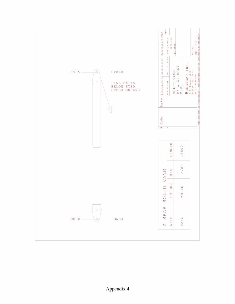
Appendix 4
R Code D
te
Material
Scale
Gen. Tol.
Design date
By
View
THIS DOCUMENT IS PROPRIETARY - REPRODUCTION
MUST BE AUTHORIZED BY BENETEAU
BENETEAU INC
P.O. Drawer 1218
Marion, SC 29571
(803) 423-4201
Part No.
Dimensions i
:n
.
amillimeters
:
Z SPAR
BADB
0
Z SPAR SOLID VANG
LINE
VANG
COLOUR
DIA
LENGTH
0000
NONE
NONE
SOLID VANG
0801501
LOWER
UPPER
OWHITE
LINE EXITSBELOW UPPER SHEAVE
06
/96
1"
9
/21
38
RF & CL MAST
15500
STBD
3/8
1985
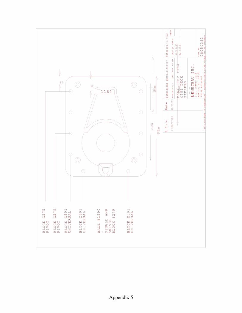
Appendix 5
R Code
Material
Scale
Gen.
Design date
By
View
THIS DOCUMENT IS PROPRIETARY - REPRODUCTION
MUST BE AUTHORIZED BY BENETEAU
BENETEAU INC
P.O. Drawer 1218
Marion, SC 29571
(803) 423-4201
Part No.
Dimensions i
:n
.
Date
:
millimeters
:
NONE
Tol.:
NONE
BADB
PROTOTYPE
0
08050
MAST STEP
Z SPAR
1164
BLOCK Z
PIVOT
BLOCK Z
PIVOT
BLOCK Z
UNIVERSAL
BLOCK Z
UNIVERSAL
BLOCK Z
UNIVERSAL
2 2 301
301
301
02/17/97
02/17/97
1164
O381 DECK
STEPPED
75
75
BALE
Z1590
+ SINGLE AND
SWIVEL
BLOCK Z279
382
160mm
230mm
215mm
285mm
25
35

Appendix 6
TRIMSCREENBLINDSYSTEM VR07
PORT 035919FIXED PMMA
HATCH 03012020LEWMAR CL S30
TRIM SCREENBLIND 035654SYSTEM VR07
NONENONE
TRIMSCREEN
SYSTEM VR07
PORT 03012506LEWMAR S03012421INCLUDED
P/O HEADLINER
ALU 038018
HATCH 03012020LEWMAR CL S30
TRIM POLYESTERSCREENBLIND 035654SYSTEM VR0
TRIMSCREEN
SYSTEM
PORTFIXED PMMA
NONE
034969
FRP 037873
VC02
2
TRIMSCREEN
SYSTEM
PORT
VR02
03012509LEWMAR S03012425
04
00
INCLUDEDCURTAIN KIT
TRIMSCREENBLINDSYSTEM
PORT
VR
LEWMAR S003012508
103012423INCLUDED
04
TRIMSCREEN
SYSTEM
PORT
VR
LEWMAR S003012508
103012423INCLUDED
05
TRIMSCREEN
SYSTEM
PORTFIXED PMMA
NONE
034969
FRP 037873
VC03
R Code Date
Material
Scale:
Gen.
Design date
By
View
THIS DOCUMENT IS PROPRIETARY - REPRODUCTION
MUST BE AUTHORIZED BY BENETEAU
BENETEAU INC
P.O. Drawer 1218
Marion, SC 29571
(803) 423-4201
Part No.
:
Dimensions in
Tol.
Millimeters
NONE
NONE
N/A
BADB
DWG No:
0
03/15/96
DECK HATCHES
O381
PROTOTYPE
03/15/96
AND
PORTS O381
O381
V1
1V
TRIMSCREEN
SYSTEM
PORT 0301250LEWMAR S0301242INCLUDED
0
VB02
HATCH 017013PMMA
W/BOARD
FRAME 036093SYSTEM VR03
TRIMSCREEN
SYSTEM VR07
PORT 03012506LEWMAR S03012421INCLUDED
HATCH 03012020LEWMAR CL S30
TRIM POLYESTERSCREENBLIND 035654SYSTEM VR0
TRIMSCREEN
SYSTEM
PORTFIXED PMMA
NONE
034969
FRP 037873
VC02
2
TRIMSCREEN
SYSTEM
PORT
VR02
03012509LEWMAR S03012425
04
00
INCLUDEDCURTAIN KIT
TRIMSCREEN
SYSTEM
PORT
VR
LEWMAR S003012508
103012423INCLUDED
TRIMSCREEN
SYSTEM
PORT
VR
LEWMAR S003012508
103012423INCLUDED
TRIMSCREENBLINDSYSTEM
PORTFIXED PMMA
NONENONE
034969
FRP 037873
VC
19
19
22
OPTION V20
OPTION
V30
OPTION
V 04
OPTION V20 OPTION V20
94
5
CURTAIN KIT
CURTAIN KIT
CURTAIN KIT
1
035652
CURTAIN KIT
WOODENP/O WOOD KIT
CURTAIN KIT
CURTAIN KIT
CURTAIN KIT
CURTAIN KIT
CURTAIN KIT
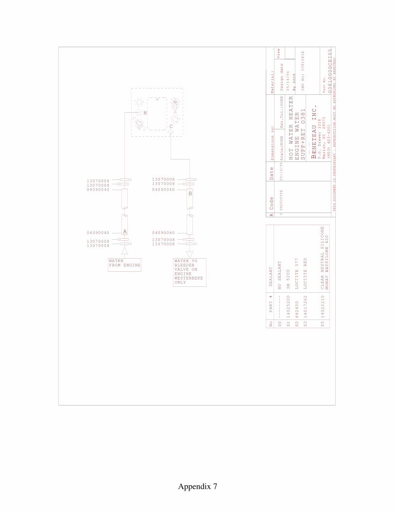
Appendix 7
R Code
Material
Scale
Gen.
Design date
By
View
THIS DOCUMENT IS PROPRIETARY - REPRODUCTION
MUST BE AUTHORIZED BY BENETEAU
BENETEAU INC
P.O. Drawer 1218
Marion, SC 29571
(803) 423-4201
Part No.
Dimensions i
:n
.
Date
:
:
NONE
Tol.:
NONE
BADB
PROTOTYPE
0
DWG No:
HOT WATER HEATER
PART #
No
S0
SEALANT
S1
3M 5200
S2
LOCTITE 577
S3
LOCTITE RED
S5
CLEAR NEUTRAL SILICONE
MOBAY BAYSILONE 400
14025200
642450
14017262
14022210
--------
NO SEALANT
ENGINE WATER
SUPP+RET
1307000813070008
130700081307000813070008
13070008
1307000813070008
FROM ENGINEWATER
H
C
0000CEI05
110EIE
1
/96
/96
B
A04090040
04090040
04090040
04090040
05/14
05/14
O38
O38
O38
WATER TOBLEEDERVALVE ONENGINEWESTERBEKEONLY
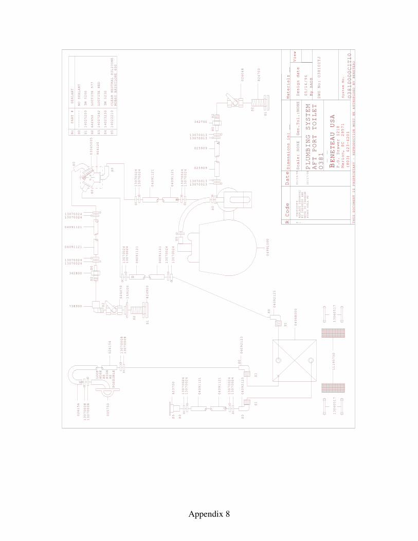
Appendix 8
R Code Date
Scale
Gen.
Design date
By
View
THIS DOCUMENT IS PROPRIETARY - REPRODUCTION
MUST BE AUTHORIZED BY BENETEAU
BENETEAU USA
P.O. Drawer 1218
Marion, SC 29571
(803) 423-4201
D:
:PROTOTYPE
0
imensions in:
__
NONE
Tol.:NONE
Material: __
BADB
DWG No:
System No.
PART #
No
S0
SEALANT
S1
3M 5200
S2
LOCTITE 577
S3
LOCTITE RED
S4
3M 5230
S5
CLEAR NEUTRAL SILICONE
MOBAY BAYSILONE 400
14025200
642450
14017262
14023230
14022210
--------
NO SEALANT
S5
S0
S0
S0
S2
S2
S1
623700
824700
026068
13070024
13070024
04091121
04091121
13070024
13070024
13070024
13070024
04091121
04091121
13070024
13070024
A
B
D
S0
04991000
13070024
13070024
04091121
04091121
13070024
13070024
G
O10ITJ
O10000CIT10
PLUMBING SYSTEM
AFT PORT TOILET
O1
S0
S0
S0
906120
03045005
S2
S0
C
0700131313070013
1307001313070013
025909
025909
342700
738900
342800
1307002413070024
04091121
04091121
1307002413070024
S2
S1
824900
159100
026070
S2
026156
13070008
026156
38
38
38
05/14/96
05/14/96
E
13070008
13070008
13070008
LOOP
HOSE
AS
HIGH
AS
POSSIBLE
005750
1REPLACE 04068002
BY 04068000 AND
MOVE TO TRANSOM
START HULL #6
10/17/96
04068000
S0
S1
S1
S0
S0
S1
04092125
04092123
04092125
11195750
13060517
13060517
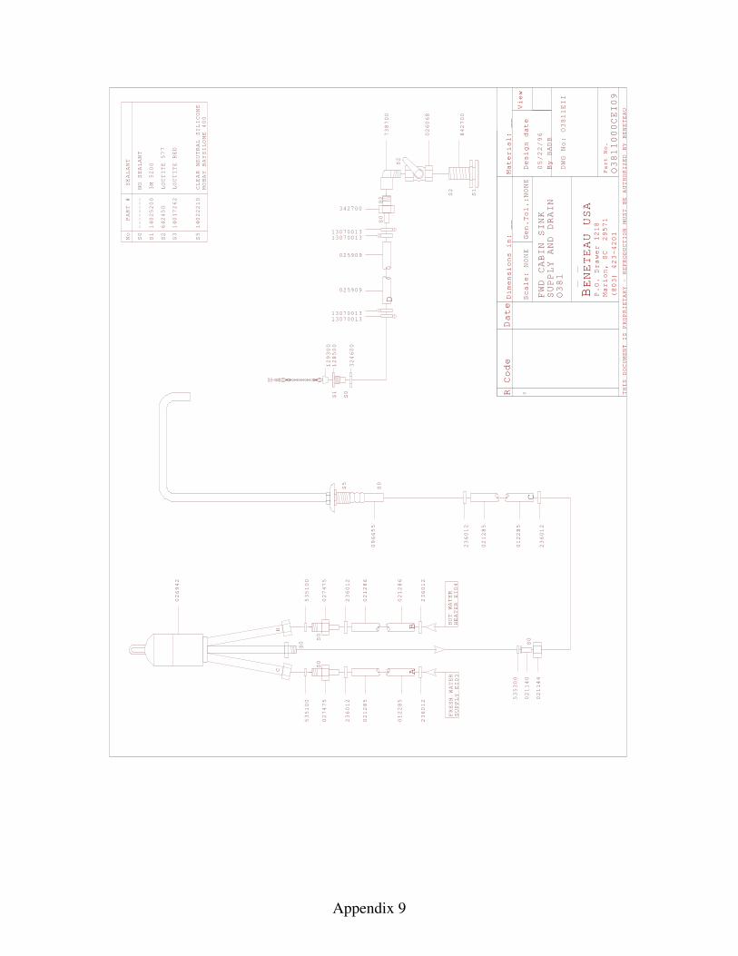
Appendix 9
R Code Date
Mater
Scale
Design date
By
View
THIS DOCUMENT IS PROPRIETARY - REPRODUCTION
MUST BE AUTHORIZED BY BENETEAU
BENETEAU USA
P.O. Drawer 1218
Marion, SC 29571
(803) 423-4201
Part No.
:0
NONE
Dimensions in:
__
ial:
Gen.Tol.:NONE
__
BADB
DWG No:
FRESH WATER
SUPPLY EI03
HOT WATER
HEATER EI04
CH
S0
S0
S0
FWD CABIN SINK
SUPPLY AND DRAIN
O381
O3811000CEI09
O3811EII
05/22/96
535100
027475
236012
021285
012285
236012
535100
027475
236012
021286
021286
236012
026942
AB
S0
S1
S2
S2
S2
025909
025909
1307001313070013
1307001313070013
342700
738700
026068
842700
S1
S0
128500
129300
324600
PART #
No
S0
SEALANT
S1
3M 5200
S2
LOCTITE 577
S3
LOCTITE RED
S5
CLEAR NEUTRAL SILICONE
MOBAY BAYSILONE 400
14025200
642450
14017262
14022210
--------
NO SEALANT
S0
535300
02114
02114
236012
021285
012285
236012
C
D
096655
S0
S5
0 4

Appendix 10
TRIMSCREENBLINDSYSTEM VR07
PORT 035919FIXED PMMA
HATCH 03012020LEWMAR CL S30
TRIM SCREENBLIND 035654SYSTEM VR07
NONENONE
TRIMSCREEN
SYSTEM VR07
PORT 03012506LEWMAR S03012421INCLUDED
P/O HEADLINER
HATCH 03012020LEWMAR CL S30
TRIM POLYESTERSCREENBLIND 035654SYSTEM VR0
TRIMSCREEN
SYSTEM
PORTFIXED PMMA
NONE
034969
FRP 037873
VC02
2
TRIMSCREEN
SYSTEM
PORT
VR02
03012509LEWMAR S03012425
04
00
INCLUDEDCURTAIN KIT
TRIMSCREENBLINDSYSTEM
PORT
VR
LEWMAR S003012508
103012423INCLUDED
04
TRIMSCREEN
SYSTEM
PORT
VR
LEWMAR S003012508
103012423INCLUDED
05
TRIMSCREEN
SYSTEM
PORTFIXED PMMA
NONE
034969
FRP 037873
VC03
R Code Date
Material
Scale:
Gen.
Design date
By
View
THIS DOCUMENT IS PROPRIETARY - REPRODUCTION
MUST BE AUTHORIZED BY BENETEAU
BENETEAU INC
P.O. Drawer 1218
Marion, SC 29571
(803) 423-4201
Part No.
:
Dimensions in
Tol.
Millimeters
NONE
NONE
N/A
BADB
DWG No:
0
03/15/96
DECK HATCHES
O381
PROTOTYPE
03/15/96
AND
PORTS O381
O381
V1
1V
TRIMSCREEN
SYSTEM
PORT 0301250LEWMAR S0301242INCLUDED
0
VB02
HATCH 017013PMMA
W/BOARD
FRAME 036093SYSTEM VR03
TRIMSCREEN
SYSTEM VR07
PORT 03012506LEWMAR S03012421INCLUDED
HATCH 03012020LEWMAR CL S30
TRIM POLYESTERSCREENBLIND 035654SYSTEM VR0
TRIMSCREEN
SYSTEM
PORTFIXED PMMA
NONE
034969
FRP 037873
VC02
2
TRIMSCREEN
SYSTEM
PORT
VR02
03012509LEWMAR S03012425
04
00
INCLUDEDCURTAIN KIT
TRIMSCREEN
SYSTEM
PORT
VR
LEWMAR S003012508
103012423INCLUDED
TRIMSCREEN
SYSTEM
PORT
VR
LEWMAR S003012508
103012423INCLUDED
TRIMSCREENBLINDSYSTEM
PORTFIXED PMMA
NONENONE
034969
FRP 037873
VC
19
19
22
OPTION V20
OPTION
V30
OPTION
V 04
OPTION V20 OPTION V20
94
5
CURTAIN KIT
CURTAIN KIT
CURTAIN KIT
1
035652
CURTAIN KIT
WOODENP/O WOOD KIT
CURTAIN KIT
CURTAIN KIT
CURTAIN KIT
CURTAIN KIT
CURTAIN KIT
1REMOVE 038018 TRIM08/14/96
NONE
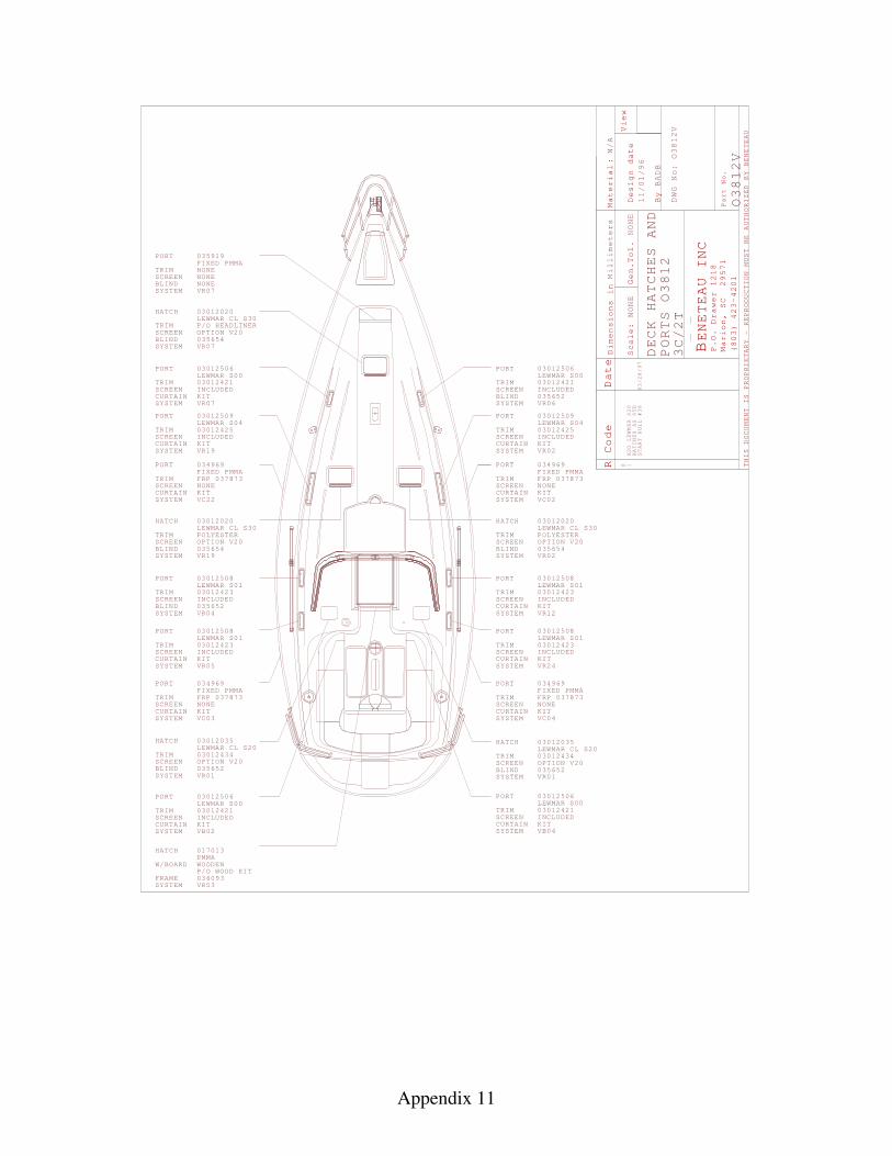
Appendix 11
TRIMSCREENBLINDSYSTEM VR07
PORT 035919FIXED PMMA
HATCH 030120LEWMAR S30
TRIM SCREENBLIND 035654SYSTEM VR07
NONENONE
TRIMSCREEN
SYSTEM VR07
PORT 03012506LEWMAR S03012421INCLUDED
P/O HEADLINER
HATCH 03012020LEWMAR CL S30
TRIM POLYESTERSCREENBLIND 035654SYSTEM
TRIMSCREEN
SYSTEM
PORTFIXED PMMA
NONE
034969
FRP 037873
VC 2
TRIMSCREEN
SYSTEM
PORT 03012509LEWMAR S03012425
04
00
INCLUDEDCURTAIN
TRIMSCREENBLINDSYSTEM
PORTLEWMAR S003012508
103012423INCLUDED
TRIMSCREEN
SYSTEM
PORT
VR
LEWMAR S003012508
103012423INCLUDED
05
TRIMSCREEN
SYSTEM
PORTFIXED PMMA
NONE
034969
FRP 037873
VC03
R Code Date
Material
Scale:
Gen.
Design date
By
View
THIS DOCUMENT IS PROPRIETARY - REPRODUCTION
MUST BE AUTHORIZED BY BENETEAU
BENETEAU INC
P.O. Drawer 1218
Marion, SC 29571
(803) 423-4201
Part No.
:
Dimensions in
Tol.
Millimeters
NONE
NONE
N/A
BADB
DWG No:
0
DECK HATCHES AND
PORTS
V
V
TRIMSCREEN
SYSTEM VR0
PORT 03012506LEWMAR S03012421INCLUDED
HATCH 03012020LEWMAR CL S30
TRIM POLYESTERSCREENBLIND 035654SYSTEM VR0
TRIMSCREEN
SYSTEM
PORTFIXED PMMA
NONE
034969
FRP 037873
VC02
2
TRIMSCREEN
SYSTEM
PORT
VR02
03012509LEWMAR S03012425
04
00
INCLUDEDCURTAIN
TRIMSCREEN
SYSTEM
PORT
VR
LEWMAR S01030124
TRIMSCREEN
SYSTEM
PORT
VR
LEWMAR S003012508
103012423INCLUDED
TRIMSCREEN
SYSTEM
PORTFIXED PMMA
NONE
034969
FRP 037873
VC
1
OPTION V20 OPTION V20
CURTAIN
CURTAIN
035652
CURTAIN
CURTAIN
CURTAIN
CURTAIN
CURTAIN
/96
OPTION V20
BLIND 0356526
CURTAIN
HATCH 017013PMMA
W/BOARD
FRAME 036093SYSTEM VR03
WOODENP/O WOOD KIT
TRIMSCREEN
SYSTEM
PORT 0301250LEWMAR S0301242INCLUDED
0
VB02CURTAIN
TRIMSCREEN
SYSTEM V
PORT 03012506LEWMAR S03012421INCLUDED
00
B04CURTAIN
VR19
2
VR19
VR 2
24
04
04
6
10
O3812
O3812
O3812
11/01
NONE
20CL
KIT
KIT
KIT
KIT
KIT
KIT
KIT
KIT
03012508
23INCLUDEDKIT
KIT
KIT
KIT
1ADD LEWMAR S20
HATCHES AS STD
START HULL #38
03/28/97
3C/2T
TRIMSCREEN
SYSTEM V
HATCH 03012035LEWMAR CL S2003012434OPTION V20
BLIND 035652R01
TRIMSCREEN
SYSTEM V
HATCH
BLIND 035652
03012035LEWMAR CL S2003012434OPTION V20
R01
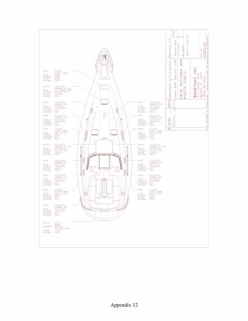
Appendix 12
TRIMSCREENBLINDSYSTEM VR07
PORT 035919FIXED PMMA
HATCH 03012020LEWMAR CL S30
TRIM SCREENBLIND 035654SYSTEM VR07
NONENONE
TRIMSCREEN
SYSTEM VR07
PORT 03012506LEWMAR S03012421INCLUDED
P/O HEADLINER
HATCH 03012020LEWMAR CL S30
TRIM POLYESTERSCREENBLIND 035654SYSTEM VR0
TRIMSCREEN
SYSTEM
PORTFIXED PMMA
NONE
034969
FRP 037873
VC02
2
TRIMSCREEN
SYSTEM
PORT
VR02
03012509LEWMAR S03012425
04
00
INCLUDEDCURTAIN KIT
TRIMSCREENBLINDSYSTEM
PORT
VR
LEWMAR S003012508
103012423INCLUDED
04
TRIMSCREEN
SYSTEM
PORT
VR
LEWMAR S003012508
103012423INCLUDED
05
TRIMSCREEN
SYSTEM
PORTFIXED PMMA
NONE
034969
FRP 037873
VC03
R Code Date
Material
Scale:
Gen.
Design date
By
View
THIS DOCUMENT IS PROPRIETARY - REPRODUCTION
MUST BE AUTHORIZED BY BENETEAU
BENETEAU INC
P.O. Drawer 1218
Marion, SC 29571
(803) 423-4201
Part No.
:
Dimensions in
Tol.
Millimeters
NONE
NONE
N/A
BADB
DWG No:
0
03/15/96
DECK HATCHES
O381
PROTOTYPE
03/15/96
AND
PORTS O381
O381
V
VTRIMSCREEN
SYSTEM
PORT 0301250LEWMAR S0301242INCLUDED
0
VB02
HATCH 017013PMMA
W/BOARD
FRAME 036093SYSTEM VR03
TRIMSCREEN
SYSTEM VR0
PORT 03012506LEWMAR S03012421INCLUDED
HATCH 03012020LEWMAR CL S30
TRIM POLYESTERSCREENBLIND 035654SYSTEM VR0
TRIMSCREEN
SYSTEM
PORTFIXED PMMA
NONE
034969
FRP 037873
VC02
2
TRIMSCREEN
SYSTEM
PORT
VR02
03012509LEWMAR S03012425
04
00
INCLUDEDCURTAIN KIT
TRIMSCREEN
SYSTEM
PORT
VR
LEWMAR S003012508
103012423INCLUDED
TRIMSCREEN
SYSTEM
PORT
VR
LEWMAR S003012508
103012423INCLUDED
TRIMSCREENBLINDSYSTEM
PORTFIXED PMMA
NONENONE
034969
FRP 037873
VC
19
19
22
OPTION V20
OPTION
V30
OPTION
V 04
OPTION V20 OPTION V20
94
5
CURTAIN KIT
CURTAIN KIT
CURTAIN KIT
035652
CURTAIN KIT
WOODENP/O WOOD KIT
CURTAIN KIT
CURTAIN KIT
CURTAIN KIT
CURTAIN KIT
1REMOVE 038018 TRIM08/14/96
NONE
3
3
3
6BLIND 035652
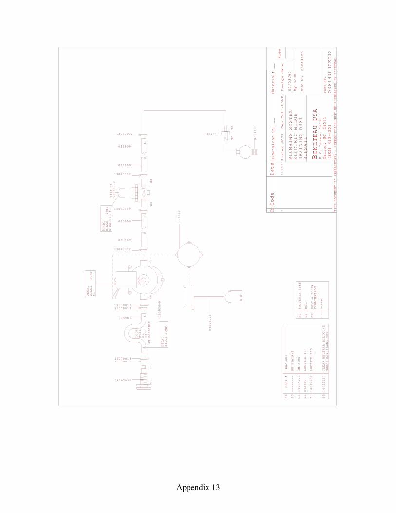
Appendix 13
R Code Date
Mater
Scale
Design date
By
View
THIS DOCUMENT IS PROPRIETARY - REPRODUCTION
MUST BE AUTHORIZED BY BENETEAU
BENETEAU USA
P.O. Drawer 1218
Marion, SC 29571
(803) 423-4201
Part No.
:
0
NONE
Dimensions in:
__
ial:
Gen.Tol.:NONE
__
BADB
PLUMBING SYSTEM
ELECTRIC BILGE
DRAINING
DWG No:
S0
S0
S0
S0
S2
S0
PART #
No
S0
SEALANT
S1
3M 5200
S2
LOCTITE 577
S3
LOCTITE RED
S5
CLEAR NEUTRAL SILICONE
MOBAY BAYSILONE 400
14025200
642450
14017262
14022210
--------
NO SEALANT
DECAL
BILGE
PUMP
STRAINER #1
DECAL
BILGE
PUMP
#1
025479
3427003070012
13070012
05092000
PART OF
13070012
13070012
05092000
025909
025909
025909
025909
1ECB
1000CEC02
LOOP
HOSE
AS
HIGH
AS POSSIBLE
S0
S1
13070011307001
13070011307001
DECAL
BILGE PUMP
025909
33
33
AB
C No
CB
BOLT
FASTENER TYPE
CK
BOLT & SCREW
COMBINATION
CS
SCREW
1
O
119200
04067050
O381
O38
38
02/03/97
02/03/97
4
4
SUNSAIL
04094103
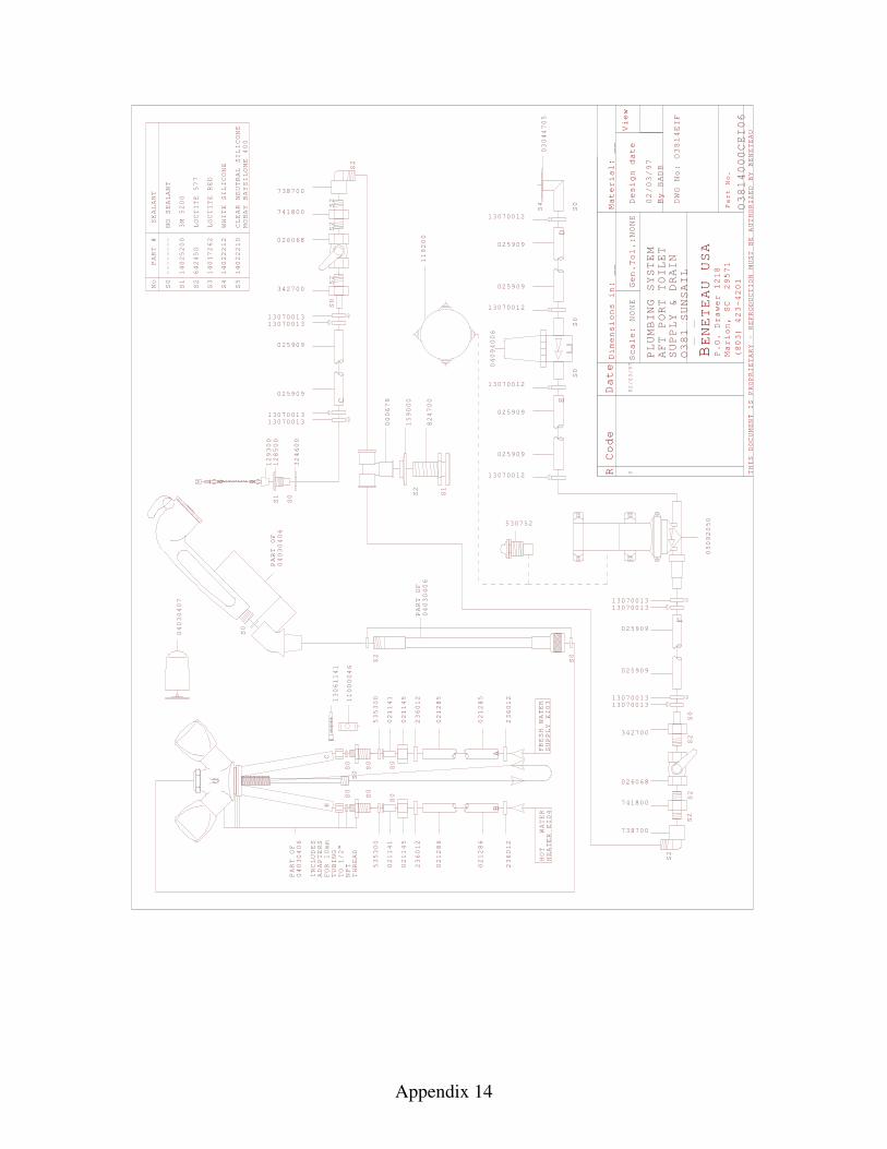
Appendix 14
R Code Date
Mater
Scale
Design date
By
View
THIS DOCUMENT IS PROPRIETARY - REPRODUCTION
MUST BE AUTHORIZED BY BENETEAU
BENETEAU USA
P.O. Drawer 1218
Marion, SC 29571
(803) 423-4201
Part No.
:
0
NONE
Dimensions in:
__
ial:
Gen.Tol.:NONE
__
BADB
PLUMBING SYSTEM
DWG No:
AFT
TOILET
SUPPLY & DRAIN
PART #
No
S0
SEALANT
S1
3M 5200
S2
LOCTITE 577
S3
LOCTITE RED
S5
CLEAR NEUTRAL SILICONE
MOBAY BAYSILONE 400
14025200
642450
14017262
14022210
--------
NO SEALANT
WATER
EI0
EI0
S0
S2
236012
02128
02128
236012
236012
02128
02128
236012
S0
S0
535300
021141
021145
021145
021141
535300
S0
S0
S0
S0
S0
PART OF
PART OF
PART OF
HOT
4FRESH WATER 3
6 655
04030406
04030406
0403040
HC
HEATER
SUPPLY
S0
6
BA
S0
S0
S0
S2
13070011307001
13070011307001
342700
13070012
13070012
13070011307001
13070011307001
13070012
13070012
C
DE
F
025909
025909
025909
025909
025909
025909
025909
025909
33
33
33
33
13061141
11000046
INCLUDES
ADAPTERS
FOR 10mm
TUBING
TO 1/2"
NPT
THREAD
04030407
S2
S1
S2
824700
159000
000679
026068
741800
738700
S2
S2
S2
S2
S2
S0
S2
342700
026068
741800
738700
PORT
O1
OEIF
O1
000CEI06
S0
38
38
03044705
S4
14022212
WHITE SILICONE
S4
S1
S0
128500
129300
324600
381
02/03/97
02/03/97
4
4
SUNSAIL
0409
006
4
530752
119200
05092050
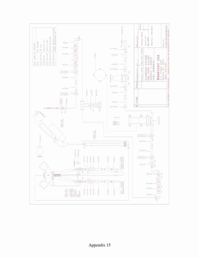
Appendix 15
R Code Date
Mater
Scale
Design date
By
View
THIS DOCUMENT IS PROPRIETARY - REPRODUCTION
MUST BE AUTHORIZED BY BENETEAU
BENETEAU USA
P.O. Drawer 1218
Marion, SC 29571
(803) 423-4201
Part No.
:
0
NONE
Dimensions in:
__
ial:
Gen.Tol.:NONE
__
BADB
PLUMBING SYSTEM
DWG No:
TOILET
SUPPLY & DRAIN
PART #
No
S0
SEALANT
S1
3M 5200
S2
LOCTITE 577
S3
LOCTITE RED
S5
CLEAR NEUTRAL SILICONE
MOBAY BAYSILONE 400
14025200
642450
14017262
14022210
--------
NO SEALANT
WATER
EI0
EI0
S0
S2
236012
02128
02128
236012
236012
02128
02128
236012
S0
S0
535300
021141
021145
021145
021141
535300
S0
S0
S0
S0
S0
PART OF
PART OF
PART OF
HOT
4FRESH WATER 3
6 655
04030406
04030406
0403040
HC
HEATER
SUPPLY
S0
6
BA
S0
S0
S0
S2
13070011307001
13070011307001
342700
13070012
13070012
13070012
13070012
C
DE
025909
025909
025909
025909
025909
025909
33
33
13061141
11000046
INCLUDES
ADAPTERS
FOR 10mm
TUBING
TO 1/2"
NPT
THREAD
04030407
S2
S1
S2
824700
159000
000679
026068
741800
738700
S2
S2
O1
O
O1
000CEI0
S0
38
38
03044705
S4
14022212
WHITE SILICONE
S4
S1
S0
128500
129300
324600
381
02/03/97
02/03/97
SUNSAIL
0409
006
4
530752
119200
05092050
5EII
59
FWD STBD
13070011307001
13070011307001
F025909
025909
33
33
S2
S0
342700
S2
S2
S2
026068
741800
738700
738700 S2
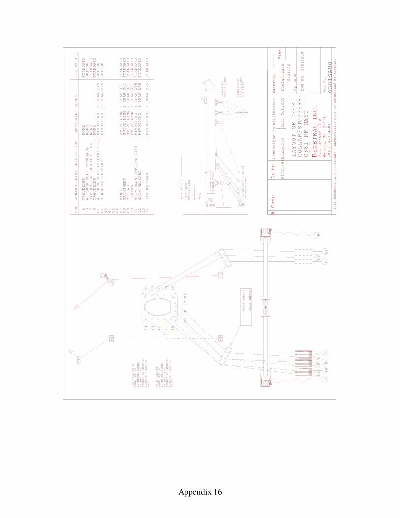
Appendix 16
R Code D
te
Material
Scale
Gen. Tol.
Design date
By
View
THIS DOCUMENT IS PROPRIETARY - REPRODUCTION
MUST BE AUTHORIZED BY BENETEAU
BENETEAU INC
P.O. Drawer 1218
Marion, SC 29571
(803) 423-4201
Part No.
Dimensions i
:n
.
amillimeters
:N/A
BADB
N/A
LAYOUT
COLLAR/STOPPERS
OF DECK
------
MAST
DWG NO:
SAU0
RF
TO
ON MAST STEP
MAIN INHAUL
FURLING LINE
MAINSHEET
VANG
RESPECTIVE BLOCK
MAIN OUTHAUL
SINGLE BLOCK
LEWMAR 9217
LEWMAR 9217
SINGLE BLOCK
LEWMAR 9
67
FIDDLE BLOCK
& BECKETT
CONTROL LINE DESCRIPTION
MAST STEP BLOCK
STD or OPT
POS
NONE
STANDARD
0 0 0
STANDARD
STANDARD
NONE
STANDARD
A B C
D
01
02
03 4 5 6 7
0 08
09
10
11
12
13
14
TRAVELLER
WHISKER POLE DOWNHAUL
JIB ROLLER FURLING LINE
TRAVELLER
WHISKER POLE TOPPING LIFT
GENNEKER HALYARD
JIB HALYARD
NONE
SWIVELLING Z SPAR 30
PIVOTTING Z SPAR 2
NONE
PIVOTTING Z SPAR 2
SWIVELLING Z SPAR 30
PIVOTTING Z SPAR 2
PIVOTTING Z SPAR 2
OPTION
OPTION
OPTION
STANDARD
STANDARD
STANDARD
SAU0
MAIN BOOM TOPPING LIFT
PIVOTTING Z SPAR 2
STANDARD
MAIN HALYARD
JIB HALYARD #1
SPINLOCK JAMMER
ON MAST
MADE OFF ON
AND
STOWED ON GENERAL
PURPOSE CLEAT ON
MAST.
07
06
09
08
13
14
12
11
10
01
00002 3 4 5
SPINLOCK JAMMER
ON MAST
MADE OFF ON
AND
STOWED ON GENERAL
PURPOSE CLEAT ON
MAST.
MAIN HALYARD
UPPER SHEAVE
LOWER SHEAVE
0
08
11
907
10
01
02
A
BC
06/21/96
06/21/96
O381
O381
O381
D
75
75 1 1
75
75
75
VANG
MAINSHEET
OUTHAUL
INHAUL
SWIVELLING Z SPAR 301
SWIVELLING
Z SPAR
301
STANDARD
STANDARD
2
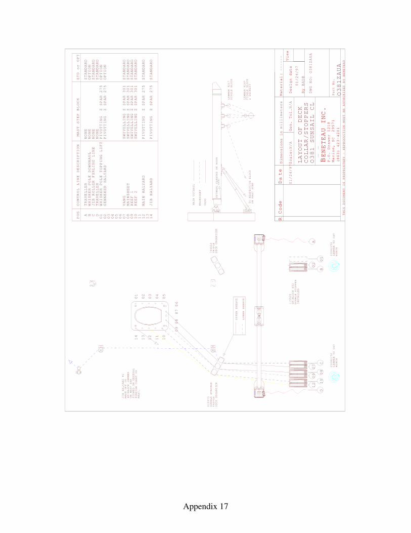
Appendix 17
R Code D
te
Material
Scale
Gen. Tol.
Design date
By
View
THIS DOCUMENT IS PROPRIETARY - REPRODUCTION
MUST BE AUTHORIZED BY BENETEAU
BENETEAU INC
P.O. Drawer 1218
Marion, SC 29571
(803) 423-4201
Part No.
Dimensions i
:n
.
amillimeters
:N/A
BADB
N/A
------
DWG NO:
TO
ON MAST STEP
MAINSHEET
VANG
RESPECTIVE BLOCK
LEWMAR 9217
SINGLE BLOCK
LEWMAR 9
67
FIDDLE BLOCK
& BECKETT
CONTROL LINE DESCRIPTION
MAST STEP BLOCK
STD or OPT
POS
NONE
STANDARD
0 0 0
STANDARD
STANDARD
NONE
STANDARD
A B C
D
01
02
03 4 5 6 7
0 08
09
10
11
12
13
14
TRAVELLER
WHISKER POLE DOWNHAUL
JIB ROLLER FURLING LINE
TRAVELLER
WHISKER POLE TOPPING LIFT
GENNEKER HALYARD
JIB HALYARD
NONE
SWIVELLING Z SPAR 30
PIVOTTING Z SPAR 2
NONE
PIVOTTING Z SPAR 2
SWIVELLING Z SPAR 30
PIVOTTING Z SPAR 2
PIVOTTING Z SPAR 2
OPTION
OPTION
OPTION
STANDARD
STANDARD
STANDARD
MAIN HALYARD
O381
75
75 1 1
75
75
VANG
MAINSHEET
SWIVELLING Z SPAR 301
SWIVELLING
Z SPAR
301
STANDARD
STANDARD
2
01/24/97
01/24/97
O381ZAUA
LAYOUT
COLLAR/STOPPERS
OF DECK
O381
SUNSAIL CL
ZAUA
OUTHAUL CLEATED ON BOOM
MAIN OUTHAUL
REEF 1
REEF 2
JIB HALYARD #1
SPINLOCK JAMMER
ON MAST
MADE OFF ON
AND
STOWED ON GENERAL
PURPOSE CLEAT ON
MAST.
07
06
09
08
13
14
12
11
10
01
00002 3 4 5
UPPER SHEAVE
LOWER SHEAVE
0
08
19
07
10
01
02
A
BC
D
015973
DOUBLE STACKED
TRIPLE
DECK ORGANIZER
TRIPLE
DECK ORGANIZER
709550
2
115505
SPINLOCK XT2
DOUBLE STOPPER
INSTALLED
03082152
LEWMAR 40 CST
WINCH
03082152
LEWMAR 40 CST
WINCH
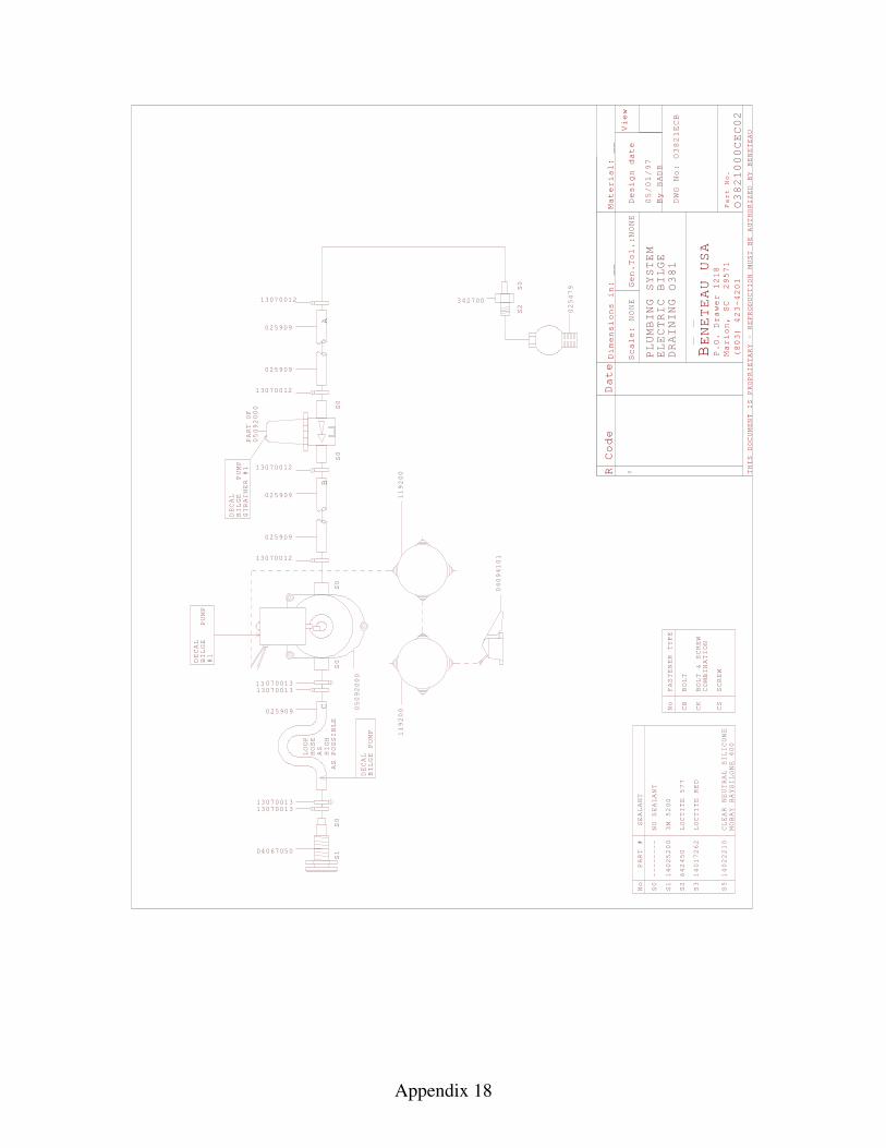
Appendix 18
R Code Date
Mater
Scale
Design date
By
View
THIS DOCUMENT IS PROPRIETARY - REPRODUCTION
MUST BE AUTHORIZED BY BENETEAU
BENETEAU USA
P.O. Drawer 1218
Marion, SC 29571
(803) 423-4201
Part No.
:0
NONE
Dimensions in:
__
ial:
Gen.Tol.:NONE
__
BADB
PLUMBING SYSTEM
ELECTRIC BILGE
DRAINING
DWG No:
S0
S0
S0
S0
S2
S0
PART #
No
S0
SEALANT
S1
3M 5200
S2
LOCTITE 577
S3
LOCTITE RED
S5
CLEAR NEUTRAL SILICONE
MOBAY BAYSILONE 400
14025200
642450
14017262
14022210
--------
NO SEALANT
DECAL
BILGE
PUMP
STRAINER #1
DECAL
BILGE
PUMP
#1
025479
3427003070012
13070012
05092000
PART OF
13070012
13070012
05092000
025909
025909
025909
025909
ECB
000CEC02
LOOP
HOSE
AS
HIGH
AS POSSIBLE
S0
S1
13070011307001
13070011307001
DECAL
BILGE PUMP
025909
33
33
AB
C No
CB
BOLT
FASTENER TYPE
CK
BOLT & SCREW
COMBINATION
CS
SCREW
1
O
119200
04067050
O381
O38
38
119200
04094101
21
05/01/97
21
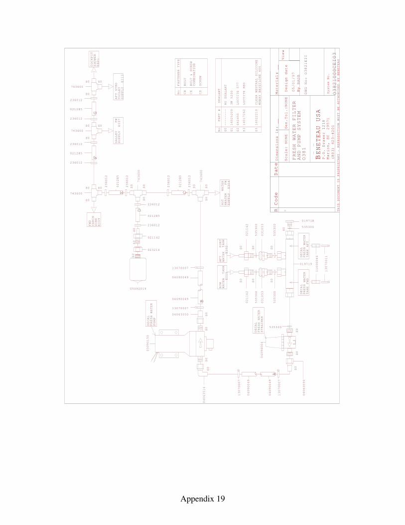
Appendix 19
R Code Date
Scale
Gen.
Design date
By
View
THIS DOCUMENT IS PROPRIETARY - REPRODUCTION
MUST BE AUTHORIZED BY BENETEAU
BENETEAU USA
P.O. Drawer 1218
Marion, SC 29571
(803) 423-4201
D:
:0
imensions in:
__
NONE
Tol.:NONE
Material: __
BADB
DWG No:
System No.
FRESH WATER FILTER
AND PUMP SYSTEM
CEI03
O381
O38
EIC
O38
000
05/
13070007
13070007
04090049
04090049
A
DECAL
FRESH WATER
PUMP
05090150
S0
S0
S0
04063514
S0
B
04063050
13070007
04090049
04090049
13070007
S2
S2
S0
236012
236012
021285
021142
023216
S0
S0
S0
743600
05092019
236012
236012
021285
S0S0
S0
021285
236012
236012
S0S0
S0
743600
021285
236012
236012
S0S0
S0
743600
743600
E
PART #
No
S0
SEALANT
S1
3M 5200
S2
LOCTITE 577
S3
LOCTITE RED
S5
CLEAR NEUTRAL SILICONE
MOBAY BAYSILONE 400
14025200
642450
14017262
14022210
--------
NO SEALANT
No
CB
BOLT
FASTENER TYPE
CK
BOLT & SCREW
COMBINATION
CS
SCREW
S0
S0
S0
743600
SUPPLY
EI
HOT
WATER
HEATER FW
04
236012
236012
021285
FWD
CABIN
SINK
EI09
COCKPI
SHOWER
E01
T
S0
S0
S0
S0
S0
S0
S0
13070011
11000046
WATER TANK
EI
WATER TANK
EI
021142
535300
031053
535300
021142
535300
031053
535300
AFT
PORT
02
BOW
15
019719
DECAL
FRESH WATER
TANK FWD
DECAL
FRESH WATER
TANK AFT
019718
535300
S0
S0
DECAL
FRESH WATER
STRAINER
04094004
535300
S0
04063050
C
D
E
FG
1
1
01/97
2
2
SUPPLY
TOILET
AFT
EI
GALLEY FW
SUPPLY EI07
STBD
13
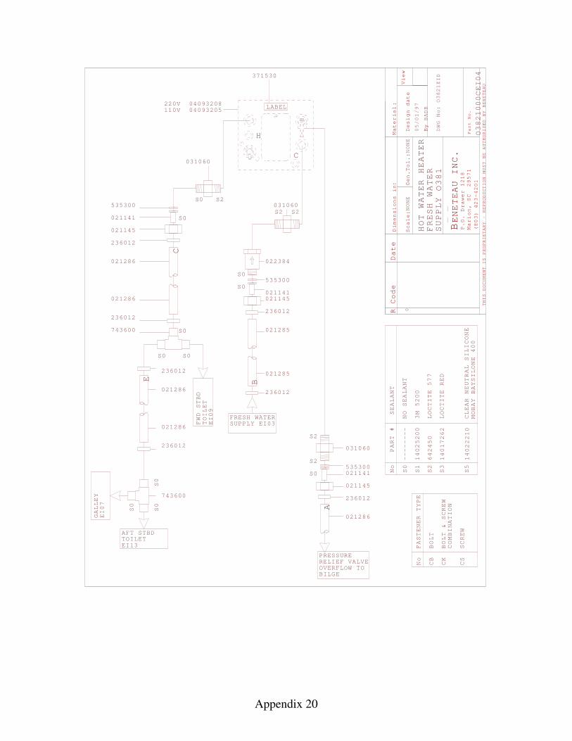
Appendix 20
R Code
Material
Scale
Gen.
Design date
By
View
THIS DOCUMENT IS PROPRIETARY - REPRODUCTION
MUST BE AUTHORIZED BY BENETEAU
BENETEAU INC
P.O. Drawer 1218
Marion, SC 29571
(803) 423-4201
Part No.
Dimensions i
:n
.
Date
:
:
NONE
Tol.:
NONE
BADB
0
DWG No:
HOT WATER HEATER
FRESH WATER
SUPPLY
PART #
No
S0
SEALANT
S1
3M 5200
S2
LOCTITE 577
S3
LOCTITE RED
S5
CLEAR NEUTRAL SILICONE
MOBAY BAYSILONE 400
14025200
642450
14017262
14022210
--------
NO SEALANT
No
CB
BOLT
FASTENER TYPE
CK
BOLT & SCREW
COMBINATION
CS
SCREW
S0
535300
021141
021145
236012
021286
021286
236012
PRESSURERELIEF VALVEOVERFLOW TOBILGE
S2
S2
S0535300021141
021145
236012
021286
S0
S0
236012
021285
021285
236012
021145021141
535300
022384
FRESH WATERSUPPLY EI03
031060
031060
371530
S S2
S2 S2
031060
A
B
C
000CEI04
H
C
LABEL110V220V
EID
S0 S0
S0
236012
021286
021286
236012
743600
E
TOILET
EI0
FWD STBD
9
O1
O
O
05/
38
38
38
0409320804093205
0
21
21
01/97
743600
S0
S0
S0
GALLEY
EI07
TOILETAFT
EI
STBD
13
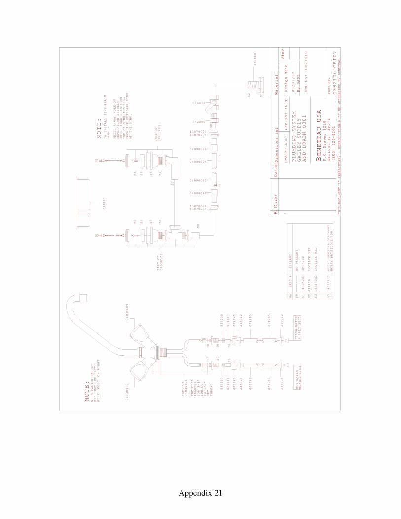
Appendix 21
R Code Date
Mater
Scale
Design date
By
View
THIS DOCUMENT IS PROPRIETARY - REPRODUCTION
MUST BE AUTHORIZED BY BENETEAU
BENETEAU USA
P.O. Drawer 1218
Marion, SC 29571
(803) 423-4201
Part No.
:0
NONE
Dimensions in:
__
ial:
Gen.Tol.:NONE
__
BADB
PLUMBING SYSTEM
DWG No:
PART #
No
S0
SEALANT
S1
3M 5200
S2
LOCTITE 577
S3
LOCTITE RED
S5
CLEAR NEUTRAL SILICONE
MOBAY BAYSILONE 400
14025200
642450
14017262
14022210
--------
NO SEALANT
GALLEY SUPPLY
AND DRAIN
236012
02128
02128
236012
236012
02128
02128
236012
S0
S0
021145
021141
535300
021145
021141
535300
S0
S0
S0
S0
PART OF
04030405
HC
FRESH WATER
SUPPLY EI03
HOT WATER
HEATER EI04
665 5
NOTE:
WHEN
FACING FAUCET
RED (HOT) ON LEFT
BLUE (COLD) ON RIGHT
AB
000CEI07
04030409
04030410
INCLUDES
ADAPTER
FOR 3/8"
TUBING
TO 1/2"
NPT
THREAD
OEIG
O
O1
S0
S2
S1
S2
824
00
9
342800
026070
1
138
38
38
05/
032981
2
2
01/97
1307002413070024
04090094
04090095
04090095
04090094
1307002413070024
S1
S1
E
S0
S0
S0
S0
S0
S0
S0
S0
S0
DRILL A 6mm HOLE ON
SEPERATION BETWEEN
BOTH SINKS 20mm FROM
TOP OF SINK
NOTE:
TO INSTALL SINK DRAIN
PLUG -
AND 20mm
FROM THE OUTBOARD SIDE
OF THE SINK.
S0
04030103
PART OF
04030103
PART OF
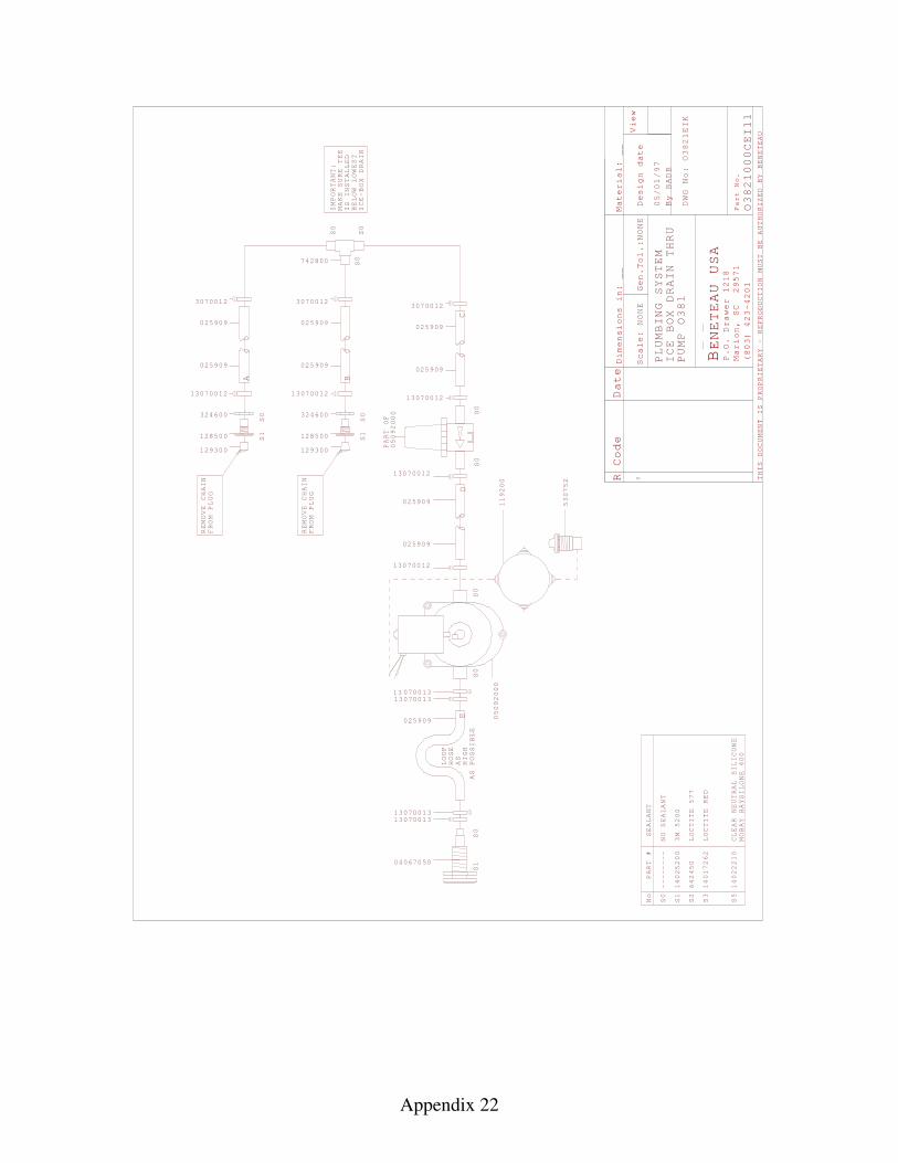
Appendix 22
R Code Date
Mater
Scale
Design date
By
View
THIS DOCUMENT IS PROPRIETARY - REPRODUCTION
MUST BE AUTHORIZED BY BENETEAU
BENETEAU USA
P.O. Drawer 1218
Marion, SC 29571
(803) 423-4201
Part No.
:0
NONE
Dimensions in:
__
ial:
Gen.Tol.:NONE
__
BADB
PLUMBING SYSTEM
DWG No:
PART #
No
S0
SEALANT
S1
3M 5200
S2
LOCTITE 577
S3
LOCTITE RED
S5
CLEAR NEUTRAL SILICONE
MOBAY BAYSILONE 400
14025200
642450
14017262
14022210
--------
NO SEALANT
ICE BOX DRAIN THRU
PUMP O
1O
EIK
O000CEI11
S0
S0
S0
S0
05092000
PART OF
13070012
13070012
05092000
119200
025909
025909
LOOP
HOSE
AS
HIGH
AS POSSIBLE
S0
S1
13 070011307001
13070011307001
025909
33
33
SS0
1128500
324600
REMOVE CHAIN
FROM PLUG
129300
13070012
3070012
025909
025909
A
04067050
1
1
05/
38
38
38
53
752
0
13070012
3070012
025909
025909
SS0
1128500
324600
REMOVE CHAIN
FROM PLUG
129300
13070012
3070012
025909
025909
742800
S0
S0
S0
2
201/97
B
ED
C
MAKE SURE TEE
IS INSTALLED
BELOW LOWEST
ICE-BOX DRAIN
IMPORTANT:
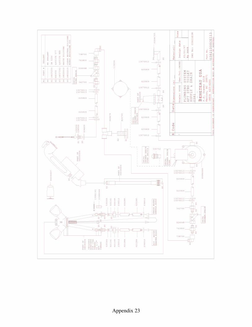
Appendix 23
R Code Date
Mater
Scale
Design date
By
View
THIS DOCUMENT IS PROPRIETARY - REPRODUCTION
MUST BE AUTHORIZED BY BENETEAU
BENETEAU USA
P.O. Drawer 1218
Marion, SC 29571
(803) 423-4201
Part No.
:
0
NONE
Dimensions in:
__
ial:
Gen.Tol.:NONE
__
BADB
PLUMBING SYSTEM
DWG No:
AFT
TOILET
SUPPLY & DRAIN
PART #
No
S0
SEALANT
S1
3M 5200
S2
LOCTITE 577
S3
LOCTITE RED
S5
CLEAR NEUTRAL SILICONE
MOBAY BAYSILONE 400
14025200
642450
14017262
14022210
--------
NO SEALANT
WATER
EI0
EI0
S0
S2
236012
02128
02128
236012
236012
02128
02128
236012
S0
S0
535300
021141
021145
021145
021141
535300
S0
S0
S0
S0
S0
PART OF
PART OF
PART OF
HOT
4FRESH WATER 3
6 655
04030406
04030406
0403040
HC
HEATER
SUPPLY
S0
6
BA
S0
S0DECAL
S0
S0
DECAL
STRAINER
SHOWER DRAIN
PUMP
SHOWER DRAIN
S0
S2
13070011307001
13070011307001
342700
13070012
13070012
PART OF
05092000
13070011307001
05092000
13070011307001
13070012
13070012
C
DE
F
025909
025909
025909
025909
025909
025909
025909
025909
33
33
33
33
13061141
11000046
INCLUDES
ADAPTERS
FOR 10mm
TUBING
TO 1/2"
NPT
THREAD
04030407
530752
S2
S1
S2
824700
000679
DECAL
SINK DRAIN
026068
741800
738700
S2
S2
S2
S2
S2
S0
S2
342700
026068
741800
738700
DECAL
SHOWER DRAIN
/9
O1
OEI
O000CEI
S0 05/
38
38
03044705
S4
14022212
WHITE SILICONE
S4
S1
S0
128500
129300
324600
3821
M
21
13
STBD
01
7
DECAL
SHOWER DRAIN
PUMP SWITCH
119200
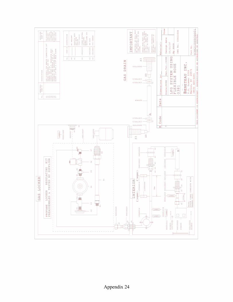
Appendix 24
R Code
Material
Scale
Gen.
Design date
By
View
THIS DOCUMENT IS PROPRIETARY - REPRODUCTION
MUST BE AUTHORIZED BY BENETEAU
BENETEAU INC
P.O. Drawer 1218
Marion, SC 29571
(803) 423-4201
Part No.
Dimensions i
:n
.
Date
:
:
NONE
Tol.:
NONE
BADB
__
_______
DWG No.
GAS LOCKER
S0
SO
INTERIOR
S2
LPG SYSTEM USING
FLEXIBLE HOSE
IMPORTANT
THRU-HULL ON HULL MUST
BE INSTALLED LOWER
THAN THRU-HULL IN GAS
LOCKER.
DRAIN HOSE MUST LEAD
DIRECTLY TO THRU-HULL
ON HULL - MAKE SURE
IT HAS NO KINKS
OR
LOOPS.
RESPECT PROTRUDING
LPG HOSE LENGTH AT
STOVE.
PROPANE
PREASSEMBLED & TESTED BY SUPPLIER
LOCKER REGULATING KIT
S0
S3
S0
S3
S2
S2
LABEL
LABEL
LABEL
S0
S0
S0
S0
S4
S0
S0
S0
S0
S4
1000mmLABEL
LABEL
LABEL
S0
No.
PART #
DESCRIPTION
________
NO SEALANT
S1
________
GASOILA SOFT
SET
WITH
TEFLON
(non toxic)
S2
14022210
CLEAR NEUTRAL
SILICONE
MOBAY
BAYSILONE
400
S3
14025200
3M 5200
S4
14014004
PVC CEMENT
GAS DRAIN
00001000
04010047
04010032
040100
04010023
13060014
13060014
11000046
04010023
04010025
00001019
10010000
04010025
04010023
00001019
00001019
00001011
A
B
300mm
000CGO01
S1
S1
S1
S1
S1
S0
01
02
03
04
05
06
07
S1
S0
BENETEAU
PART #
No.
DESCRIPTION
0 0 0 0 0 0 0
LPG PIGTAIL FOR REMOTE CONNECTION 24"
STREET TEE 1/4"
1 2 3 4 5 6 7
SUPPLIER
PART #
1014140224
GAUGE PRESSURE 300 PSI
6901400
622-1414
SINGLE STAGE L.P. REGULATOR BODY S/SREG-UP
REDUCING HEX NIPPLE 3/8" x 1/4"
603-1438
SOLENOID LOW PRESSURE BRASS
13007708.2
ELBOW 1/4" MPT x 3/8" MALE FLARE
602-1438
STOVE COMES COMPLETE WITH
BARREL BOLT
NOTE:
025909
1307001
1307001
1307001
1307001
3
3
3
3
04067050
04067050
1GOA
640900
2
12070108
04010005
04010006
038005
O381
O38
O38
1
6
0
05/01/97
2
2
003855
003855
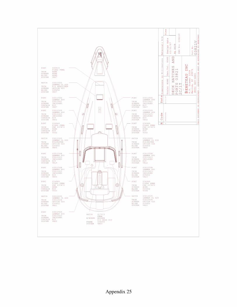
Appendix 25
TRIMSCREENBLINDSYSTEM VR07
PORT 035919FIXED PMMA
HATCH 03012020LEWMAR CL S30
TRIM SCREENBLIND 035654SYSTEM VR07
NONENONE
TRIMSCREEN
SYSTEM VR07
PORT 03012506LEWMAR S03012421INCLUDED
P/O HEADLINER
HATCH 03012020LEWMAR CL S30
TRIM POLYESTERSCREENBLIND 035654SYSTEM VR0
TRIMSCREEN
SYSTEM
PORTFIXED PMMA
NONE
034969
FRP 037873
VC02
2
TRIMSCREEN
SYSTEM
PORT
VR02
03012509LEWMAR S03012425
04
00
INCLUDEDCURTAIN KIT
TRIMSCREEN
SYSTEM
PORT
VR
LEWMAR S003012508
103012423INCLUDED
TRIMSCREEN
SYSTEM
PORT
VR
LEWMAR S003012508
103012423INCLUDED
05
TRIMSCREEN
SYSTEM
PORTFIXED PMMA
NONE
034969
FRP 037873
VC03
R Code Date
Material
Scale:
Gen.
Design date
By
View
THIS DOCUMENT IS PROPRIETARY - REPRODUCTION
MUST BE AUTHORIZED BY BENETEAU
BENETEAU INC
P.O. Drawer 1218
Marion, SC 29571
(803) 423-4201
Part No.
:
Dimensions in
Tol.
Millimeters
NONE
NONE
N/A
BADB
DWG No:
0
03/
DECK HATCHES
O38
PROTOTYPE
AND
PORTS O38
O38
V1
1V
TRIMSCREEN
SYSTEM VR07
PORT 03012506LEWMAR S03012421INCLUDED
HATCH 03012020LEWMAR CL S30
TRIM POLYESTERSCREENBLIND 035654SYSTEM VR0
TRIMSCREEN
SYSTEM
PORTFIXED PMMA
NONE
034969
FRP 037873
VC02
2
TRIMSCREEN
SYSTEM
PORT
VR02
03012509LEWMAR S03012425
04
00
INCLUDEDCURTAIN KIT
TRIMSCREEN
SYSTEM
PORT
VR
LEWMAR S003012508
103012423INCLUDED
TRIMSCREEN
SYSTEM
PORT
VR
LEWMAR S003012508
103012423INCLUDED
TRIMSCREENBLINDSYSTEM
PORTFIXED PMMA
NONE
034969
FRP 037873
VC
1
OPTION V20
OPTION V20 OPTION V20
CURTAIN KIT
CURTAIN KIT
1
CURTAIN KIT
CURTAIN KIT
CURTAIN KIT
CURTAIN KIT
CURTAIN KIT
NONE
03/31/97
2
31/97
2
2
19CURTAIN KIT
2
08
BLIND 035652
035652
23
TRIMSCREEN
SYSTEM
PORT 0301250LEWMAR S0301242INCLUDED
0
VB02
94
5
CURTAIN KIT
TRIMSCREEN
SYSTEM
03012LEWMAR 030124
V
HATCH 035CL S20
34OPTION V20035652R01
BLIND
TRIMSCREENBLINDSYSTEM V
035652
HATCH 03012035LEWMAR CL S2003012434OPTION V20
R01
HATCH 017013PMMA
W/BOARD
FRAME 036093SYSTEM VR03
WOODENP/O WOOD KIT
2C/1T
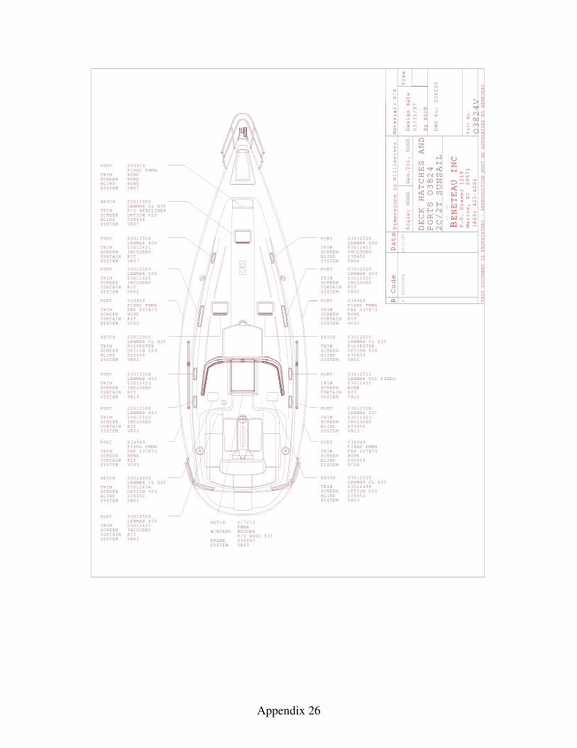
Appendix 26
TRIMSCREENBLINDSYSTEM VR07
PORT 035919FIXED PMMA
HATCH 03012020LEWMAR CL S30
TRIM SCREENBLIND 035654SYSTEM VR07
NONENONE
TRIMSCREEN
SYSTEM VR07
PORT 03012506LEWMAR S03012421INCLUDED
P/O HEADLINER
HATCH 03012020LEWMAR CL S30
TRIM POLYESTERSCREENBLIND 035654SYSTEM VR0
TRIMSCREEN
SYSTEM
PORTFIXED PMMA
NONE
034969
FRP 037873
VC02
2
TRIMSCREEN
SYSTEM
PORT
VR02
03012509LEWMAR S03012425
04
00
INCLUDEDCURTAIN KIT
TRIMSCREEN
SYSTEM
PORT
VR
LEWMAR S003012508
103012423INCLUDED
TRIMSCREEN
SYSTEM
PORT
VR
LEWMAR S003012508
103012423INCLUDED
05
TRIMSCREEN
SYSTEM
PORTFIXED PMMA
NONE
034969
FRP 037873
VC03
R Code Date
Material
Scale:
Gen.
Design date
By
View
THIS DOCUMENT IS PROPRIETARY - REPRODUCTION
MUST BE AUTHORIZED BY BENETEAU
BENETEAU INC
P.O. Drawer 1218
Marion, SC 29571
(803) 423-4201
Part No.
:
Dimensions in
Tol.
Millimeters
NONE
NONE
N/A
BADB
DWG No:
0
03/
DECK HATCHES
O38
PROTOTYPE
AND
PORTS O38
O38
V
V
TRIMSCREEN
SYSTEM VR0
PORT 03012506LEWMAR S03012421INCLUDED
HATCH 03012020LEWMAR CL S30
TRIM POLYESTERSCREENBLIND 035654SYSTEM VR0
TRIMSCREEN
SYSTEM
PORTFIXED PMMA
NONE
034969
FRP 037873
VC02
2
TRIMSCREEN
SYSTEM
PORT
VR02
03012509LEWMAR S03012425
04
00
INCLUDEDCURTAIN KIT
TRIMSCREEN
SYSTEM
PORT
VR
LEWMAR S0030125
1030124
TRIMSCREEN
SYSTEM
PORT
VR
LEWMAR S003012508
103012423INCLUDED
TRIMSCREENBLINDSYSTEM
PORTFIXED PMMA
NONE
034969
FRP 037873
VC
1
OPTION V20
OPTION V20 OPTION V20
CURTAIN KIT
CURTAIN KIT
CURTAIN KIT
CURTAIN KIT
CURTAIN KIT
CURTAIN KIT
NONE
03/31/97
2
31/97
2
2
19CURTAIN KIT
2
08
BLIND 035652
035652
23
TRIMSCREEN
SYSTEM
PORT 0301250LEWMAR S0301242INCLUDED
0
VB02
94
5
CURTAIN KIT
TRIMSCREEN
SYSTEM
03012LEWMAR 030124
V
HATCH 035CL S20
34OPTION V20035652R0
BLIND
TRIMSCREENBLINDSYSTEM V
035652
HATCH 03012035LEWMAR CL S2003012434OPTION V20
R
HATCH 017013PMMA
W/BOARD
FRAME 036093SYSTEM VR03
WOODENP/O WOOD KIT
2C/2T
BLIND 0356526
4SUNSAIL
4
4
13FIXED
35NONE
5 23
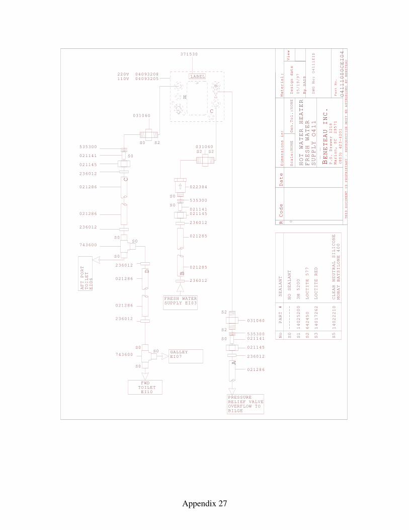
Appendix 27
R Code
Material
Scale
Gen.
Design date
By
View
THIS DOCUMENT IS PROPRIETARY - REPRODUCTION
MUST BE AUTHORIZED BY BENETEAU
BENETEAU INC
P.O. Drawer 1218
Marion, SC 29571
(803) 423-4201
Part No.
Dimensions i
:n
.
Date
:
:
NONE
Tol.:
NONE
BADB
0
DWG No:
HOT WATER HEATER
FRESH WATER
SUPPLY
PART #
No
S0
SEALANT
S1
3M 5200
S2
LOCTITE 577
S3
LOCTITE RED
S5
CLEAR NEUTRAL SILICONE
MOBAY BAYSILONE 400
14025200
642450
14017262
14022210
--------
NO SEALANT
S0
535300
021141
021145
236012
021286
021286
236012
PRESSURERELIEF VALVEOVERFLOW TOBILGE
S2
S2
S0535300021141
021145
236012
021286
S0
S0
236012
021285
021285
236012
021145021141
535300
022384
FRESH WATERSUPPLY EI03
031060
031060
371530
S S2
S2 S2
031060
A
B
C
000CEI04
H
C
LABEL110V220V
EID
236012
021286
021286
236012
D
1
1
05/1
0409320804093205
0
9/97
O411
O411
O411
S0
S0
743600S0
S0
S0S0
TOILET
AFT PORT
EI06
743600GALLEYEI07
FWDTOILETEI10
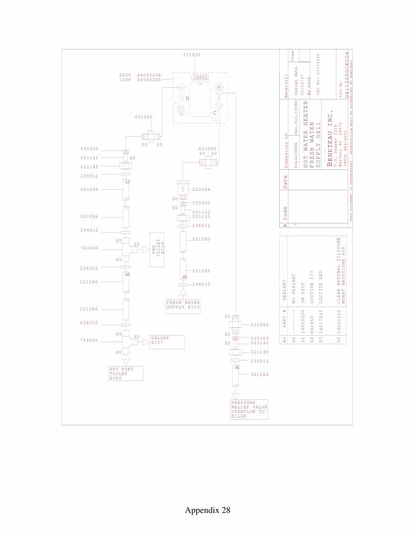
Appendix 28
R Code
Material
Scale
Gen.
Design date
By
View
THIS DOCUMENT IS PROPRIETARY - REPRODUCTION
MUST BE AUTHORIZED BY BENETEAU
BENETEAU INC
P.O. Drawer 1218
Marion, SC 29571
(803) 423-4201
Part No.
Dimensions i
:n
.
Date
:
:
NONE
Tol.:
NONE
BADB
0
DWG No:
HOT WATER HEATER
FRESH WATER
SUPPLY
PART #
No
S0
SEALANT
S1
3M 5200
S2
LOCTITE 577
S3
LOCTITE RED
S5
CLEAR NEUTRAL SILICONE
MOBAY BAYSILONE 400
14025200
642450
14017262
14022210
--------
NO SEALANT
S0
535300
021141
021145
236012
021286
021286
236012
PRESSURERELIEF VALVEOVERFLOW TOBILGE
S2
S2
S0535300021141
021145
236012
021286
S0
S0
236012
021285
021285
236012
021145021141
535300
022384
FRESH WATERSUPPLY EI03
031060
031060
371530
S S2
S2 S2
031060
A
B
C
000CEI04
H
C
LABEL110V220V
EID
05/1
0409320804093205
0
9/97
O411
O411
O411
S0
S0
743600S0
FWD
TOILET
EI10
236012
021286
021286
236012
S0
S0
TOILETAFT PORT
EI06
GALLEYEI07743600
S0
2
2
E
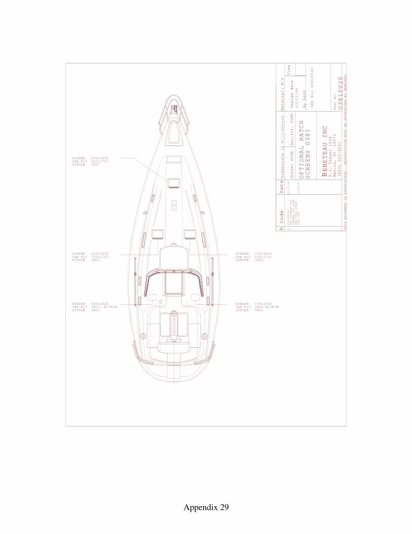
Appendix 29
R Code Date
Material
Scale:
Gen.
Design date
By
View
THIS DOCUMENT IS PROPRIETARY - REPRODUCTION
MUST BE AUTHORIZED BY BENETEAU
BENETEAU INC
P.O. Drawer 1218
Marion, SC 29571
(803) 423-4201
Part No.
:
Dimensions in
Tol.
Millimeters
NONE
NONE
N/A
BADB
DWG No:
0
03/15/96
PROTOTYPE
03/15/96
OPTIONAL HATCH
SCREENS O381
O3810V20
O3810V20
SCREEN 03012630TAB KIT 03012701
SCREEN 03012630TAB KIT 03012701
SCREEN 03012630TAB KIT 03012701
SYSTEM VR02
SYSTEM VR07
SYSTEM VR02
1ADD SCREENS FOR
LEWMAR S20 PORT
AND STBD START
HULL #38
03/28/97
SCREEN 030126 0TAB KITSYSTEM VR0
2INCL. W/TRIM
1
SCREEN 030126 0TAB KITSYSTEM VR0
2INCL.W/TRIM
1
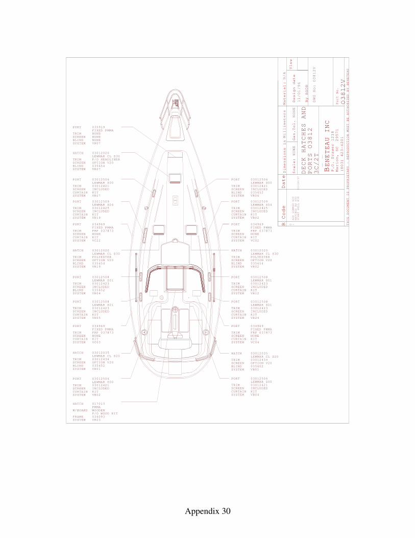
Appendix 30
TRIMSCREENBLINDSYSTEM VR07
PORT 035919FIXED PMMA
HATCH 030120LEWMAR S30
TRIM SCREENBLIND 035654SYSTEM VR07
NONENONE
TRIMSCREEN
SYSTEM VR07
PORT 03012506LEWMAR S03012421INCLUDED
P/O HEADLINER
HATCH 03012020LEWMAR CL S30
TRIM POLYESTERSCREENBLIND 035654SYSTEM
TRIMSCREEN
SYSTEM
PORTFIXED PMMA
NONE
034969
FRP 037873
VC 2
TRIMSCREEN
SYSTEM
PORT 03012509LEWMAR S03012425
04
00
INCLUDEDCURTAIN
TRIMSCREENBLINDSYSTEM
PORTLEWMAR S003012508
103012423INCLUDED
TRIMSCREEN
SYSTEM
PORT
VR
LEWMAR S003012508
103012423INCLUDED
05
TRIMSCREEN
SYSTEM
PORTFIXED PMMA
NONE
034969
FRP 037873
VC03
R Code Date
Material
Scale:
Gen.
Design date
By
View
THIS DOCUMENT IS PROPRIETARY - REPRODUCTION
MUST BE AUTHORIZED BY BENETEAU
BENETEAU INC
P.O. Drawer 1218
Marion, SC 29571
(803) 423-4201
Part No.
:
Dimensions in
Tol.
Millimeters
NONE
NONE
N/A
BADB
DWG No:
0
DECK HATCHES AND
PORTS
V
V
TRIMSCREEN
SYSTEM VR0
PORT 03012506LEWMAR S03012421INCLUDED
HATCH 03012020LEWMAR CL S30
TRIM POLYESTERSCREENBLIND 035654SYSTEM VR0
TRIMSCREEN
SYSTEM
PORTFIXED PMMA
NONE
034969
FRP 037873
VC02
2
TRIMSCREEN
SYSTEM
PORT
VR02
03012509LEWMAR S03012425
04
00
INCLUDEDCURTAIN
TRIMSCREEN
SYSTEM
PORT
VR
LEWMAR S01030124
TRIMSCREEN
SYSTEM
PORT
VR
LEWMAR S003012508
103012423INCLUDED
TRIMSCREEN
SYSTEM
PORTFIXED PMMA
NONE
034969
FRP 037873
VC
1
OPTION V20 OPTION V20
CURTAIN
CURTAIN
035652
CURTAIN
CURTAIN
CURTAIN
CURTAIN
CURTAIN
/96
OPTION V20
BLIND 0356526
CURTAIN
HATCH 017013PMMA
W/BOARD
FRAME 036093SYSTEM VR03
WOODENP/O WOOD KIT
TRIMSCREEN
SYSTEM
PORT 0301250LEWMAR S0301242INCLUDED
0
VB02CURTAIN
TRIMSCREEN
SYSTEM V
PORT 03012506LEWMAR S03012421INCLUDED
00
B04CURTAIN
VR19
2
VR19
VR 2
24
04
04
6
10
O3812
O3812
O3812
11/01
NONE
20CL
KIT
KIT
KIT
KIT
KIT
KIT
KIT
KIT
03012508
23INCLUDEDKIT
KIT
KIT
KIT
1ADD LEWMAR S20
HATCHES AS STD
START HULL #38
03/28/97
3C/2T
TRIMSCREEN
SYSTEM V
HATCH 03012035LEWMAR CL S2003012434OPTION V20
BLIND 035652R01
TRIMSCREEN
SYSTEM V
HATCH
BLIND 035652
03012035LEWMAR CL S2003012434OPTION V20
R01
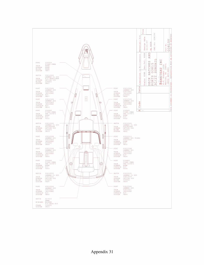
Appendix 31
TRIMSCREENBLINDSYSTEM VR07
PORT 035919FIXED PMMA
HATCH 030120LEWMAR S30
TRIM SCREENBLIND 035654SYSTEM VR07
NONENONE
TRIMSCREEN
SYSTEM VR07
PORT 03012506LEWMAR S03012421INCLUDED
P/O HEADLINER
HATCH 03012020LEWMAR CL S30
TRIM POLYESTERSCREENBLIND 035654SYSTEM
TRIMSCREEN
SYSTEM
PORTFIXED PMMA
NONE
034969
FRP 037873
VC 2
TRIMSCREEN
SYSTEM
PORT 03012509LEWMAR S03012425
04
00
INCLUDEDCURTAIN
TRIMSCREENBLINDSYSTEM
PORTLEWMAR S003012508
103012423INCLUDED
TRIMSCREEN
SYSTEM
PORT
VR
LEWMAR S003012508
103012423INCLUDED
05
TRIMSCREEN
SYSTEM
PORTFIXED PMMA
NONE
034969
FRP 037873
VC03
R Code Date
Material
Scale:
Gen.
Design date
By
View
THIS DOCUMENT IS PROPRIETARY - REPRODUCTION
MUST BE AUTHORIZED BY BENETEAU
BENETEAU INC
P.O. Drawer 1218
Marion, SC 29571
(803) 423-4201
Part No.
:
Dimensions in
Tol.
Millimeters
NONE
NONE
N/A
BADB
DWG No:
0
DECK HATCHES AND
PORTS
V
V
TRIMSCREEN
SYSTEM VR0
PORT 03012506LEWMAR S03012421INCLUDED
HATCH 03012020LEWMAR CL S30
TRIM POLYESTERSCREENBLIND 035654SYSTEM VR0
TRIMSCREEN
SYSTEM
PORTFIXED PMMA
NONE
034969
FRP 037873
VC02
2
TRIMSCREEN
SYSTEM
PORT
VR02
03012509LEWMAR S03012425
04
00
INCLUDEDCURTAIN
TRIMSCREEN
SYSTEM
PORT
VR
LEWMAR S01
TRIMSCREEN
SYSTEM
PORT
VR
LEWMAR S003012508
103012423INCLUDED
TRIMSCREEN
SYSTEM
PORTFIXED PMMA
NONE
034969
FRP 037873
VC
1
OPTION V20 OPTION V20
CURTAIN
CURTAIN
035652
CURTAIN
CURTAIN
CURTAIN
CURTAIN
CURTAIN
OPTION V20
BLIND 0356526
CURTAIN
HATCH 017013PMMA
W/BOARD
FRAME 036093SYSTEM VR03
WOODENP/O WOOD KIT
TRIMSCREEN
SYSTEM
PORT 0301250LEWMAR S0301242INCLUDED
0
VB02CURTAIN
TRIMSCREEN
SYSTEM V
PORT 03012506LEWMAR S03012421INCLUDED
00
B04CURTAIN
VR19
2
VR19
VR 2
24
04
04
6
10
O381
O381
O381
NONE
20CL
KIT
KIT
KIT
KIT
KIT
KIT
KIT
KIT
KIT
KIT
KIT
KIT
5
55
01/21/97
03012513FIXED
03012435NONE
HATCH 03012035LEWMAR CL S20
TRIM 03012434SCREENBLIND 035652SYSTEM VR24
HATCH 03012035LEWMAR CL S20
TRIM 03012434SCREENBLIND 035652SYSTEM VR05
3C/2T
SUNSAIL
OPTION V20OPTION V20
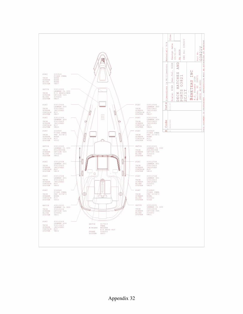
Appendix 32
TRIMSCREENBLINDSYSTEM VR07
PORT 035919FIXED PMMA
HATCH 03012020LEWMAR CL S30
TRIM SCREENBLIND 035654SYSTEM VR07
NONENONE
TRIMSCREEN
SYSTEM VR07
PORT 03012506LEWMAR S03012421INCLUDED
P/O HEADLINER
HATCH 03012020LEWMAR CL S30
TRIM POLYESTERSCREENBLIND 035654SYSTEM VR0
TRIMSCREEN
SYSTEM
PORTFIXED PMMA
NONE
034969
FRP 037873
VC02
2
TRIMSCREEN
SYSTEM
PORT
VR02
03012509LEWMAR S03012425
04
00
INCLUDEDCURTAIN KIT
TRIMSCREEN
SYSTEM
PORT
VR
LEWMAR S003012508
103012423INCLUDED
TRIMSCREEN
SYSTEM
PORT
VR
LEWMAR S003012508
103012423INCLUDED
05
TRIMSCREEN
SYSTEM
PORTFIXED PMMA
NONE
034969
FRP 037873
VC03
R Code Date
Material
Scale:
Gen.
Design date
By
View
THIS DOCUMENT IS PROPRIETARY - REPRODUCTION
MUST BE AUTHORIZED BY BENETEAU
BENETEAU INC
P.O. Drawer 1218
Marion, SC 29571
(803) 423-4201
Part No.
:
Dimensions in
Tol.
Millimeters
NONE
NONE
N/A
BADB
DWG No:
0
03/
DECK HATCHES
O38
PROTOTYPE
AND
PORTS O38
O38
V1
1V
TRIMSCREEN
SYSTEM VR07
PORT 03012506LEWMAR S03012421INCLUDED
HATCH 03012020LEWMAR CL S30
TRIM POLYESTERSCREENBLIND 035654SYSTEM VR0
TRIMSCREEN
SYSTEM
PORTFIXED PMMA
NONE
034969
FRP 037873
VC02
2
TRIMSCREEN
SYSTEM
PORT
VR02
03012509LEWMAR S03012425
04
00
INCLUDEDCURTAIN KIT
TRIMSCREEN
SYSTEM
PORT
VR
LEWMAR S003012508
103012423INCLUDED
TRIMSCREEN
SYSTEM
PORT
VR
LEWMAR S003012508
103012423INCLUDED
TRIMSCREENBLINDSYSTEM
PORTFIXED PMMA
NONE
034969
FRP 037873
VC
1
OPTION V20
OPTION V20 OPTION V20
CURTAIN KIT
CURTAIN KIT
1
CURTAIN KIT
CURTAIN KIT
CURTAIN KIT
CURTAIN KIT
CURTAIN KIT
NONE
03/31/97
2
31/97
2
2
19CURTAIN KIT
2
08
BLIND 035652
035652
23
TRIMSCREEN
SYSTEM
PORT 0301250LEWMAR S0301242INCLUDED
0
VB02
94
5
CURTAIN KIT
TRIMSCREEN
SYSTEM
03012LEWMAR 030124
V
HATCH 035CL S20
34OPTION V20035652R01
BLIND
TRIMSCREENBLINDSYSTEM V
035652
HATCH 03012035LEWMAR CL S2003012434OPTION V20
R01
HATCH 017013PMMA
W/BOARD
FRAME 036093SYSTEM VR03
WOODENP/O WOOD KIT
2C/1T

Appendix 33
TRIMSCREENBLINDSYSTEM VR07
PORT 035919FIXED PMMA
HATCH 03012020LEWMAR CL S30
TRIM SCREENBLIND 035654SYSTEM VR07
NONENONE
TRIMSCREEN
SYSTEM VR07
PORT 03012506LEWMAR S03012421INCLUDED
P/O HEADLINER
HATCH 03012020LEWMAR CL S30
TRIM POLYESTERSCREENBLIND 035654SYSTEM VR0
TRIMSCREEN
SYSTEM
PORTFIXED PMMA
NONE
034969
FRP 037873
VC02
2
TRIMSCREEN
SYSTEM
PORT
VR02
03012509LEWMAR S03012425
04
00
INCLUDEDCURTAIN KIT
TRIMSCREEN
SYSTEM
PORT
VR
LEWMAR S003012508
103012423INCLUDED
TRIMSCREEN
SYSTEM
PORT
VR
LEWMAR S003012508
103012423INCLUDED
05
TRIMSCREEN
SYSTEM
PORTFIXED PMMA
NONE
034969
FRP 037873
VC03
R Code Date
Material
Scale:
Gen.
Design date
By
View
THIS DOCUMENT IS PROPRIETARY - REPRODUCTION
MUST BE AUTHORIZED BY BENETEAU
BENETEAU INC
P.O. Drawer 1218
Marion, SC 29571
(803) 423-4201
Part No.
:
Dimensions in
Tol.
Millimeters
NONE
NONE
N/A
BADB
DWG No:
0
03/
DECK HATCHES
O38
PROTOTYPE
AND
PORTS O38
O38
V
V
TRIMSCREEN
SYSTEM VR0
PORT 03012506LEWMAR S03012421INCLUDED
HATCH 03012020LEWMAR CL S30
TRIM POLYESTERSCREENBLIND 035654SYSTEM VR0
TRIMSCREEN
SYSTEM
PORTFIXED PMMA
NONE
034969
FRP 037873
VC02
2
TRIMSCREEN
SYSTEM
PORT
VR02
03012509LEWMAR S03012425
04
00
INCLUDEDCURTAIN KIT
TRIMSCREEN
SYSTEM
PORT
VR
LEWMAR S003012508
103012423INCLUDED
TRIMSCREEN
SYSTEM
PORT
VR
LEWMAR S003012508
103012423INCLUDED
TRIMSCREENBLINDSYSTEM
PORTFIXED PMMA
NONE
034969
FRP 037873
VC
1
OPTION V20
OPTION V20 OPTION V20
CURTAIN KIT
CURTAIN KIT
CURTAIN KIT
CURTAIN KIT
CURTAIN KIT
CURTAIN KIT
NONE
03/31/97
2
31/97
2
2
19CURTAIN KIT
2
08
BLIND 035652
035652
23
TRIMSCREEN
SYSTEM
PORT 0301250LEWMAR S0301242INCLUDED
0
VB02
94
5
CURTAIN KIT
TRIMSCREEN
SYSTEM
03012LEWMAR 030124
V
HATCH 035CL S20
34OPTION V20035652R01
BLIND
TRIMSCREENBLINDSYSTEM V
035652
HATCH 03012035LEWMAR CL S2003012434OPTION V20
R01
HATCH 017013PMMA
W/BOARD
FRAME 036093SYSTEM VR03
WOODENP/O WOOD KIT
32C/2T
3
3
BLIND 0356526