dealer support manual v1 - just add...
TRANSCRIPT

Dealer Support
Manual V1.2
2G HD over IP Dealer Support Manual – Page 2
©2011 Just Add Power Cardware Co, Inc. All rights reserved. Unauthorized use or disclosure prohibited. V1.2
Contents Just Add Power 2G OSD Messages............................................................................................................................. 3
Simple Type 1 Serial Communications using RS232 over IP ports ............................................................................. 4
Type 2 Binary Serial Communications using RS232 over IP ports .............................................................................. 5
Advanced Controls Overview: .................................................................................................................................... 6
How to Access the Console: ................................................................................................................................... 6
How to determine the 2G board's IP address: ....................................................................................................... 6
FAQs: ...................................................................................................................................................................... 7
Console APIs Description: ...................................................................................................................................... 8
Debug Console APIs: .......................................................................................................................................... 8
Configurations APIs: ........................................................................................................................................... 9
UART Port 1 APIs: ............................................................................................................................................... 9
Configuration Options List: .............................................................................................................................. 10
Example console session for visual learners: ....................................................................................................... 12
Practical application examples: ........................................................................................................................... 12
Diagnostic Console access without InstallerPro UART2 console cables .................................................................. 13
Using IR Manager VBS-HDMI-IR104 with 2G RS232 ports ....................................................................................... 14
VBS-HDMI-IR104 RS232 Command List: .............................................................................................................. 16
Adjust IR Command Length (Short vs. Long).................................................................................................... 16
IR Control Commands ...................................................................................................................................... 17
RS-232Port IR Memory Write Command ......................................................................................................... 19
HDMI Video Resolutions supported: ....................................................................................................................... 20
NOTES: ..................................................................................................................................................................... 25
2G HD over IP Dealer Support Manual – Page 3
©2011 Just Add Power Cardware Co, Inc. All rights reserved. Unauthorized use or disclosure prohibited. V1.2
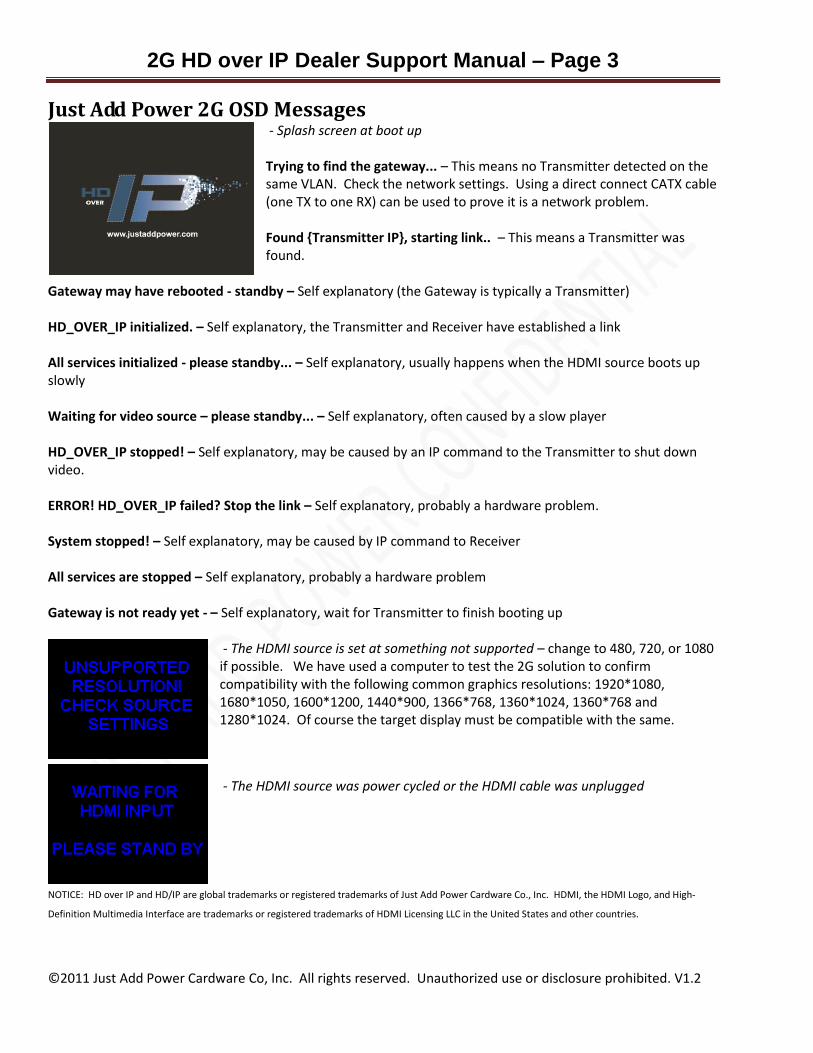
Just Add Power 2G OSD Messages - Splash screen at boot up Trying to find the gateway... – This means no Transmitter detected on the same VLAN. Check the network settings. Using a direct connect CATX cable (one TX to one RX) can be used to prove it is a network problem. Found {Transmitter IP}, starting link.. – This means a Transmitter was found.
Gateway may have rebooted - standby – Self explanatory (the Gateway is typically a Transmitter) HD_OVER_IP initialized. – Self explanatory, the Transmitter and Receiver have established a link All services initialized - please standby... – Self explanatory, usually happens when the HDMI source boots up slowly Waiting for video source – please standby... – Self explanatory, often caused by a slow player HD_OVER_IP stopped! – Self explanatory, may be caused by an IP command to the Transmitter to shut down video. ERROR! HD_OVER_IP failed? Stop the link – Self explanatory, probably a hardware problem. System stopped! – Self explanatory, may be caused by IP command to Receiver All services are stopped – Self explanatory, probably a hardware problem Gateway is not ready yet - – Self explanatory, wait for Transmitter to finish booting up
- The HDMI source is set at something not supported – change to 480, 720, or 1080 if possible. We have used a computer to test the 2G solution to confirm compatibility with the following common graphics resolutions: 1920*1080, 1680*1050, 1600*1200, 1440*900, 1366*768, 1360*1024, 1360*768 and 1280*1024. Of course the target display must be compatible with the same.
- The HDMI source was power cycled or the HDMI cable was unplugged
NOTICE: HD over IP and HD/IP are global trademarks or registered trademarks of Just Add Power Cardware Co., Inc. HDMI, the HDMI Logo, and High-
Definition Multimedia Interface are trademarks or registered trademarks of HDMI Licensing LLC in the United States and other countries.

2G HD over IP Dealer Support Manual – Page 4
©2011 Just Add Power Cardware Co, Inc. All rights reserved. Unauthorized use or disclosure prohibited. V1.2
Simple Type 1 Serial Communications using RS232 over IP ports The 2G's have been shipped with the RS232 ports set for Type 1 ASCII mode. There is also a Type 2 BINARY
mode option, but that is a bit more complicated (more on BINARY mode later). In order to "connect" a
Transmitter RS232 port to a Receiver RS232 port in ASCII mode you do the following:
1. Enter client access mode by sending the byte "0x0E" (Ctrl-N, aka hex 0E ) to the Transmitter RS232 port.
This will break an existing link to another Receiver.
2. Link to the Receiver Mac Address with the ASCII Terminal Connect command (ast_c). The Receiver Mac
Address is shown on the TV status screen in the lower right hand corner as CLIENT ID. Baud rates up to
115200 are supported.
a. ast_c <macaddr><baudrate><break code override><enter>
b. For example, if your Receiver Mac Address is ABCD12345678 and you are wanting a typical
9600, 8, N, 1 connections you would issue the command
ast_c ABCD12345678 9600-8N1 [ENTER]
c. In the example below we see a HyperTerminal session where I used 2G RS232 Over IP to
connect to my Netgear switch RS232 port and issued the SHOW VLAN command.
AT THIS POINT I PRESSED CTRL-N to break the session

2G HD over IP Dealer Support Manual – Page 5
©2011 Just Add Power Cardware Co, Inc. All rights reserved. Unauthorized use or disclosure prohibited. V1.2
3. You should now be connected to the terminal prompt from the attached RS232 device connected to the
Receiver. The session will stay connected until you issue the hex 0E command (Ctrl-N) again. This does
mean you cannot use hex 0E for any ASCII control commands during a communications session, which
may be a minor inconvenience for some RS232 devices. You can overcome this limitation by using the
optional “break code override” function when you establish the link to the target. For example: "ast_c
0200000000e1 9600-8n1 f0" to set "f0" as the break code of this link session. The new break code is
only applied to the current link session. After the current link session is disconnected, the break code
will reset to the default "0E". The valid break code range is any character from 01 to ff hex.
NOTE: The Break Code Override function was introduced with firmware A1.32. Older firmware does
not support this function. Always check your firmware version before attempting to use new features.
Now it gets interesting. With one RS232 connection to your host processor device, you can have a 2G
Transmitter dedicated to serial communications. You can think of this as sort of a serial master device. As long
as there is no HDMI source connected to the serial master, it can be on the same VLAN as another Transmitter
and there will be no disruption to the HDMI content being watched on the Receiver. With typical switches, this
means you will need to issue a SWITCHPORT command to get the serial master on the same VLAN as the target
Receiver before you issue the "ast_c" connect command.
Type 2 Binary Serial Communications using RS232 over IP ports The 2G's have been shipped with the RS232 ports set for Type 1 ASCII mode. There is also a Type 2 BINARY
mode option. Details on how to change the serial port from Type 1 to Type 2 are provided later on in this
document.
With Type 2 serial communication there is no manual initiation of the link between the Transmitter and
Receiver. Instead, the Transmitter is always trying to talk to all the Receivers simultaneously, until one Receiver
echoes a response to the Transmitter. Then a point-to-point bidirectional link is established that will break after
a user specified period of no data activity designated by the ASTPARAM variable 'soip_type2_token_timeout'.
This form of communications is intended for advanced RS232 devices that need to talk to each other in Binary
mode. Using an isolated VLAN would be one method of having more specific control over which Receiver(s) can
respond to the RS232 transmission.

2G HD over IP Dealer Support Manual – Page 6
©2011 Just Add Power Cardware Co, Inc. All rights reserved. Unauthorized use or disclosure prohibited. V1.2
Advanced Controls Overview: This section of the Dealers Manual document describes the advanced commands which can be used with the Just Add Power 2G processor console. The 2G processor uses Linux OS and the console is driven by a BusyBox shell. The debug console is set to UART port 2 using baud rate at 115200-8n1 (requires a special cable to connect to the PCB). Through console APIs, developers can control certain 2G firmware features and functions
Notation: • Console commands starting with "$": Means they are global console commands. This kind of command is executed under Linux shell console from any location.
• Console commands starting as "$./": Means they are exclusive console commands and must be executed within the path "/usr/local/bin". These commands must be prefaced with “./” (dot-slash).
How to Access the Console:
There are two ways to access the console: 1. UART2 debug port on the 2G printed circuit board: It is a RS232 interface using 115200-8n1 baud rate settings. Developers can attach to this debug port to access console. This RS232 Console port requires a special cable.
2. Use telnet: Every 2G Transmitter/Receiver has Telnetd and a telnet client built in (port 24 is the open port, „root‟ is the userid, and there is no password). Developers can use one 2G telnet client to connect to any other 2G board on the same VLAN or write their own program using telnet protocol to connect to any 2G board through an Ethernet network.
How to determine the 2G board's IP address:
The 2G firmware default setting is for "autoip" mode and uses the 169.254.xxx.xxx private IP domain range. The IP of target 2G boards is resolved by its hostname using mDNS protocol. If you have access to the InstallerPro software utilities (licensed separately) It is possible to use “static IP” or “DHCP” instead of “autoip”, but it is not recommended for most users. If a developer chooses “static IP” or “DHCP”, they must be responsible to maintain their own IP mapping to know which 2G board is using which IP address. When using the recommended “autoip” mode there are several supported methods available to resolve the IP addresses:
1. 2G Receiver‟s HDMI GUI: The 2G Receiver‟s HDMI GUI will display the Receiver‟s IP address and the connected Transmitter‟s IP address.
2. Console APIs: Two console APIs are provided: a. astresname: use this command to resolve a target's IP address by providing target‟s hostname. b. node_list: use this command to list all found 2G boards' hostname and IP address.
3. Use mDNS protocol tools. For example: a. Bonjour: http://developer.apple.com/networking/bonjour/ or
http://www.science.uva.nl/research/air/wiki/mDNSResponderInstallation b. pyZeroConfig: http://sourceforge.net/projects/pyzeroconf/files/

2G HD over IP Dealer Support Manual – Page 7
©2011 Just Add Power Cardware Co, Inc. All rights reserved. Unauthorized use or disclosure prohibited. V1.2
FAQs:
General Configuration: 1) How can I discover all the other 2G boards on the same LAN?
Use the telnet or debug console to attach to the target board
Login as “root” and then change directory “cd usr/local/bin”
Start discover all: $./node_list
Start discover hosts: $./node_list -t host
Start discover clients: $./node_list -t client
The result will be shown on the console, where hosts are 2G Transmitters and clients are 2G Receivers
2) How do I read/write target board's UART port 1 (/dev/ttyS0)?
Use telnet or debug console to attach to target board
Use stty to configure the UART port 1. Ex: $stty 115200 -F /dev/ttyS0 => set UART port 1's baud rate to 115200.
To start read: $cat /dev/ttyS0 & => UART data will be redirected to console
To stop read: $pkill cat
To start write: $cat > /dev/ttyS0 => console input will be redirected to UART
To stop write: press "ctrl+c" (0x03)
3) What if I need to include “ctrl+c (0c03) in my RS232 command string?
You can use the console function $printf instead to send commands out port 1 (/dev/ttyS0) Example: $ printf "\x02 PLAY \x03" > /dev/ttyS0
4) How do I configure UART port 1 (/dev/ttyS0) for non-"Serial over IP" usage?
UART port 1 is typically used for "Serial over IP" feature. Developers who want to manually control UART port 1 need to disable the "Serial over IP" feature.
To configure UART port 1, please use "stty" command. See "Console APIs Description" below for details.
5) How do I change the IP Address and Netmask of the Transmitters or Receivers
Use InstallerPro software utilities – InstallerPro is purchased separately and has a one time license fee for authorized dealers.
2G HD over IP Dealer Support Manual – Page 8
©2011 Just Add Power Cardware Co, Inc. All rights reserved. Unauthorized use or disclosure prohibited. V1.2
Console APIs Description:
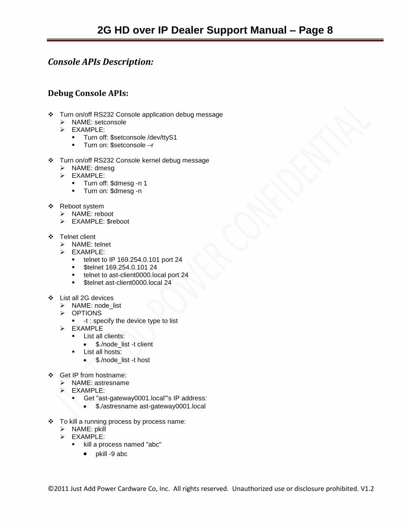
Debug Console APIs:
Turn on/off RS232 Console application debug message
NAME: setconsole EXAMPLE:
Turn off: $setconsole /dev/ttyS1 Turn on: $setconsole –r
Turn on/off RS232 Console kernel debug message
NAME: dmesg EXAMPLE:
Turn off: $dmesg -n 1 Turn on: $dmesg -n
Reboot system
NAME: reboot EXAMPLE: $reboot
Telnet client
NAME: telnet EXAMPLE:
telnet to IP 169.254.0.101 port 24 $telnet 169.254.0.101 24 telnet to ast-client0000.local port 24 $telnet ast-client0000.local 24
List all 2G devices
NAME: node_list OPTIONS
-t : specify the device type to list EXAMPLE
List all clients:
$./node_list -t client List all hosts:
$./node_list -t host
Get IP from hostname: NAME: astresname EXAMPLE:
Get "ast-gateway0001.local"'s IP address:
$./astresname ast-gateway0001.local
To kill a running process by process name: NAME: pkill EXAMPLE:
kill a process named "abc"
pkill -9 abc

2G HD over IP Dealer Support Manual – Page 9
©2011 Just Add Power Cardware Co, Inc. All rights reserved. Unauthorized use or disclosure prohibited. V1.2
Configurations APIs:
Access configurations from flash:
NAME: astparam OPTIONS
r : read from RO section g : read from RW section s : write to RW section flush : clear all settings in RW section including random generated MAC address save : saves changes to flash memory
EXAMPLE:
read " no_soip" setting from RO section:
$./astparam r no_soip
read " s0_baudrate" setting from RW section:
$./astparam g s0_baudrate write " soip_type2" setting as "y" to RW section:
$./astparam s soip_type2 y clear all settings in RW section:
$./astparam flush clear “no_soip” setting in RW section:
$./astparam s no_soip
Reset setting to factory default:
NAME: reset_to_default.sh DESCRIPTION: resets the RW section but keeps the random generated MAC address. A system reboot
is required to take effect. EXAMPLE:
$./reset_to_default.sh
UART Port 1 APIs:
Setup /dev/ttyS0: NAME: stty DESCRIPTION: used to configure terminal parameters, such as baud rate and whether characters will be
echoed Example: set baudrate to 115200
$stty 115200 -F /dev/ttyS0 Reference http://linux.about.com/od/lna_guide/a/gdelna38t01.htm for more details on stty
2G HD over IP Dealer Support Manual – Page 10
©2011 Just Add Power Cardware Co, Inc. All rights reserved. Unauthorized use or disclosure prohibited. V1.2
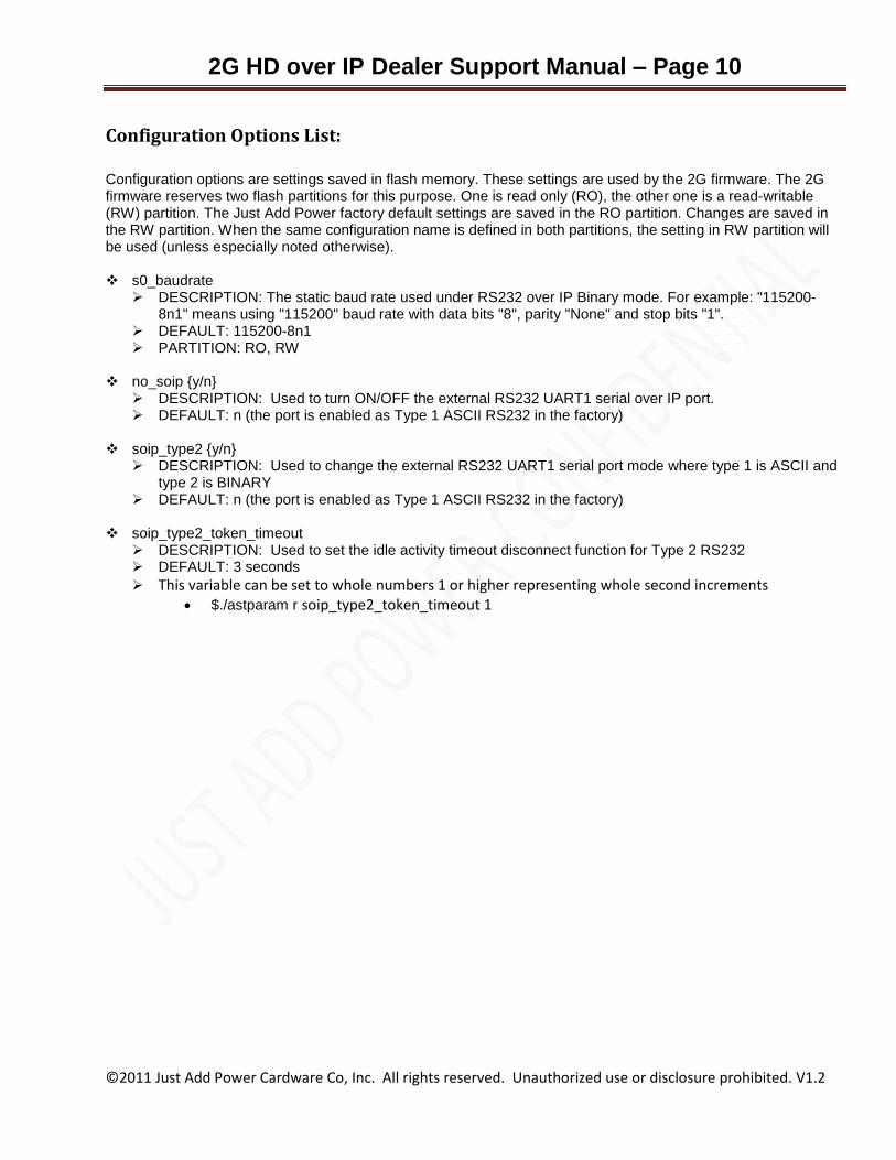
Configuration Options List:
Configuration options are settings saved in flash memory. These settings are used by the 2G firmware. The 2G firmware reserves two flash partitions for this purpose. One is read only (RO), the other one is a read-writable (RW) partition. The Just Add Power factory default settings are saved in the RO partition. Changes are saved in the RW partition. When the same configuration name is defined in both partitions, the setting in RW partition will be used (unless especially noted otherwise).
s0_baudrate
DESCRIPTION: The static baud rate used under RS232 over IP Binary mode. For example: "115200-8n1" means using "115200" baud rate with data bits "8", parity "None" and stop bits "1".
DEFAULT: 115200-8n1 PARTITION: RO, RW
no_soip {y/n}
DESCRIPTION: Used to turn ON/OFF the external RS232 UART1 serial over IP port. DEFAULT: n (the port is enabled as Type 1 ASCII RS232 in the factory)
soip_type2 {y/n}
DESCRIPTION: Used to change the external RS232 UART1 serial port mode where type 1 is ASCII and type 2 is BINARY
DEFAULT: n (the port is enabled as Type 1 ASCII RS232 in the factory)
soip_type2_token_timeout DESCRIPTION: Used to set the idle activity timeout disconnect function for Type 2 RS232 DEFAULT: 3 seconds
This variable can be set to whole numbers 1 or higher representing whole second increments
$./astparam r soip_type2_token_timeout 1

2G HD over IP Dealer Support Manual – Page 11
©2011 Just Add Power Cardware Co, Inc. All rights reserved. Unauthorized use or disclosure prohibited. V1.2

2G HD over IP Dealer Support Manual – Page 12
©2011 Just Add Power Cardware Co, Inc. All rights reserved. Unauthorized use or disclosure prohibited. V1.2
Example console session for visual learners:
The following is an example of actual console commands being issued from a Telnet session (logged into IP 169.254.4.244 on port 24):
Take note that the node_list command was issued from /usr/local/bin and was prefaced with “dot-slash”. The response indicates that there were 3 Receivers and 1 Transmitter (the gateway) on that LAN/VLAN.
Practical application examples:
1) Change the external serial-over-ip UART1 port to Type 1 ASCII mode
./astparam s no_soip n // enable serial over ip port
./astparam s soip_type2 n // “no” to Type 2 means “yes” to type 1
./astparam save // save to flash reboot // reboot and load new parameters
2) Change the external serial-over-ip UART1 port to Type 2 BINARY mode ./astparam s no_soip n // enable serial over ip port
./astparam s soip_type2 y // “yes” to Type 2
./astparam save // save to flash
reboot // reboot and load new parameters

2G HD over IP Dealer Support Manual – Page 13
©2011 Just Add Power Cardware Co, Inc. All rights reserved. Unauthorized use or disclosure prohibited. V1.2
Diagnostic Console access without InstallerPro UART2 console cables This process describes how to collect basic diagnostic information from Just Add Power 2G devices. This method
is presented for dealers who have not purchased the InstallerPro authorized dealer support kit and cables.
While it may help us to solve a problem, the InstallerPro console cables collect much more data and can help us
to more quickly identify and solve problems.
1. Reboot the Receiver and wait for the splash screen to pass. Then take note of the LOCAL IP. This is the IP
Address of the Receiver attached to that screen.
2. Connect a PC to an Ethernet port on the LAN switch that is on the same VLAN as the Receiver.
3. Start a TELNET session
4. Within TELNET issue the command “SET LOGFILE DEBUG.TXT”
5. Within TELNET issue the command “SET LOGGING”
6. Now link to the device to be analyzed with the O command using port 24. For example, if the IP Address of
the target Receiver is 164.264.4.244 you would issue the command
“o 169.254.4.244 24”.
7. If you have everything correct you will now see a LOGIN prompt like this:
ast-client82B29C680559 login:
8. Login to the 2G box with userid “root”, you should see something like this:
login: can't chdir to home directory '/root'
BusyBox v1.10.3 (2010-08-02 10:53:26 CST) built-in shell (ash)
Enter 'help' for a list of built-in commands.
9. Now enter the 2G Console command “dmesg” (a ton of data will fly by and be copied to debug.txt)
10. Now enter the 2G Console command “exit”
11. You should be back to TELNET. Enter the TELNET command “q” to QUIT.
12. Locate the DEBUG.TXT file on your PC and email it to [email protected]
13. We will analyze the results and advise you what can be done to solve the problem
WARNING: If you run the diagnostic on multiple transmitters or receivers you should rename DEBUG.TXT to a
name that will be easy to associate with the device being analyzed (i.e. call it Bedroom-TV-debug.txt or PS3-
debug.txt.
2G HD over IP Dealer Support Manual – Page 14
©2011 Just Add Power Cardware Co, Inc. All rights reserved. Unauthorized use or disclosure prohibited. V1.2
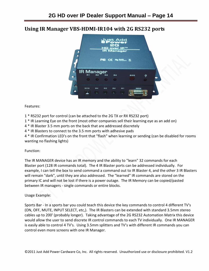
Using IR Manager VBS-HDMI-IR104 with 2G RS232 ports
Features:
1 * RS232 port for control (can be attached to the 2G TX or RX RS232 port) 1 * IR Learning Eye on the front (most other companies sell their learning eye as an add on) 4 * IR Blaster 3.5 mm ports on the back that are addressed discretely
4 * IR Blasters to connect to the 3.5 mm ports with adhesive pads
4 * IR Confirmation LED's on the front that "flash" when learning or sending (can be disabled for rooms wanting no flashing lights)
Function:
The IR MANAGER device has an IR memory and the ability to "learn" 32 commands for each Blaster port (128 IR commands total). The 4 IR Blaster ports can be addressed individually. For example, I can tell the box to send command a command out to IR Blaster 4, and the other 3 IR Blasters will remain "dark", until they are also addressed. The "learned" IR commands are stored on the primary IC and will not be lost if there is a power outage. The IR Memory can be copied/pasted between IR managers - single commands or entire blocks.
Usage Example:
Sports Bar - In a sports bar you could teach this device the key commands to control 4 different TV's (ON, OFF, MUTE, INPUT SELECT, etc,). The IR Blasters can be extended with standard 3.5mm stereo cables up to 200' (probably longer). Taking advantage of the 2G RS232 Automation Matrix this device would allow the user to send discrete IR control commands to each TV individually. One IR MANAGER is easily able to control 4 TV's. Using 3.5mm splitters and TV’s with different IR commands you can control even more screens with one IR Manager.

2G HD over IP Dealer Support Manual – Page 15
©2011 Just Add Power Cardware Co, Inc. All rights reserved. Unauthorized use or disclosure prohibited. V1.2
Distributed Resource Control - Imagine there is a TV and a Blu-Ray player at one end of the house and the owner wants to watch/operate that from another room. You can teach this device the necessary commands to control the TV, Blu-Ray Player, and perhaps 2 other sources in that remote location. Taking advantage of the 2G RS232 Automation Matrix this device would allow the user to send discrete IR control commands to the Blu-Ray, and could also control the TV.
Essentially you have got a "learning" universal remote control can work with any control system with RS232 support that can be addressed from anywhere else. Control4, Crestron, AMX, RTI, URC, Savant, etc. There will probably be a tangent market for the IR MANAGER for use in non HD over IP installations. This device will be very simple to support with our MediaSwitcher software which can be operated on PC, Linux, Mac, and portable devices such is iPhone and iPads.
IR Manager Internal Memory Characteristics IR Manager has 4 memory blocks, which can store Short or Long IR commands. The default
value is Short Data (448Byte), which is enough for IR control of most consumer electronic equipment. The Long Data (704 Byte) is provided for unique requirements. When the IR command uses Short Data (448Byte), it can support 32 commands per block; when it is Long Data, (704 Byte), it can support 16 commands per block
IR Learning Mode and the Power LED When IR Manager executes the learning function, the Power LED will flash off, and on again
while waiting for the IR command to be received by the IR eye. You can use the Power the
Power LED to see if the learning function is successful. The light will stay ON when the command is accepted into memory. It will turn OFF if the command is not learned within the allotted time.
Using RS-232 to write IR commands to the IR Manager When the IR Manager Memory is successfully updated the Power LED will flash once, which
means the data is accepted; if the Power LED flashes 6 times this means the write to flash memory has failed, most likely due to a data error.
IR-1, IR-2, IR-3, IR-4 LED function: The LED will flash ON when the IR command is being sent successfully. If you try to send a
command from a memory block that does not contain a learned IR command the port’s LED and the Power LED will flash 6 times, which means this port has not learned any IR data for that command. The IR-1, IR-2, IR-3, and IR-4 LED’s can be disabled by removing the associated jumpers on the IR Manager printed circuit board.
2G HD over IP Dealer Support Manual – Page 16
©2011 Just Add Power Cardware Co, Inc. All rights reserved. Unauthorized use or disclosure prohibited. V1.2
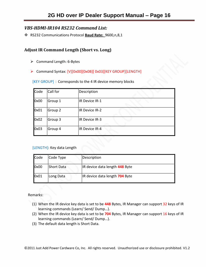
VBS-HDMI-IR104 RS232 Command List:
RS232 Communications Protocol Baud Rate: 9600,n,8,1
Adjust IR Command Length (Short vs. Long)
Command Length: 6-Bytes
Command Syntax: [V][0x00][0x0B][ 0x03][KEY GROUP][LENGTH]
[KEY GROUP]:Corresponds to the 4 IR device memory blocks
Code Call for Description
0x00 Group 1 IR Device IR-1
0x01 Group 2 IR Device IR-2
0x02 Group 3 IR Device IR-3
0x03 Group 4 IR Device IR-4
[LENGTH]: Key data Length
Code Code Type Description
0x00 Short Data IR device data length 448 Byte
0x01 Long Data IR device data length 704 Byte
Remarks:
(1) When the IR device key data is set to be 448 Bytes, IR Manager can support 32 keys of IR learning commands (Learn/ Send/ Dump…).
(2) When the IR device key data is set to be 704 Bytes, IR Manager can support 16 keys of IR learning commands (Learn/ Send/ Dump…).
(3) The default data length is Short Data.

2G HD over IP Dealer Support Manual – Page 17
©2011 Just Add Power Cardware Co, Inc. All rights reserved. Unauthorized use or disclosure prohibited. V1.2
IR Control Commands
Command Length: 6-Bytes
Command Syntaxt: [V][0x00][0x0B] [MODE] [KEY GROUP] [KEY#]
[MODE]: IR Mode (Transmit, Receive, or Dump)
Code Mode Description
0x00 TX IR Sending mode
0x01 RX IR Learning mode
0x02 DUMP IR Key data reading mode
[KEY GROUP]: 4 IR Device Code
Code Call for Description
0x00 Group 1 IR Device IR-1
0x01 Group 2 IR Device IR-2
0x02 Group 3 IR Device IR-3
0x03 Group 4 IR Device IR-4
2G HD over IP Dealer Support Manual – Page 18
©2011 Just Add Power Cardware Co, Inc. All rights reserved. Unauthorized use or disclosure prohibited. V1.2
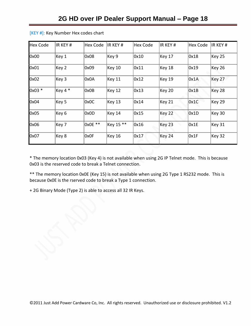
[KEY #]: Key Number Hex codes chart
Hex Code IR KEY # Hex Code IR KEY # Hex Code IR KEY # Hex Code IR KEY #
0x00 Key 1 0x08 Key 9 0x10 Key 17 0x18 Key 25
0x01 Key 2 0x09 Key 10 0x11 Key 18 0x19 Key 26
0x02 Key 3 0x0A Key 11 0x12 Key 19 0x1A Key 27
0x03 * Key 4 * 0x0B Key 12 0x13 Key 20 0x1B Key 28
0x04 Key 5 0x0C Key 13 0x14 Key 21 0x1C Key 29
0x05 Key 6 0x0D Key 14 0x15 Key 22 0x1D Key 30
0x06 Key 7 0x0E ** Key 15 ** 0x16 Key 23 0x1E Key 31
0x07 Key 8 0x0F Key 16 0x17 Key 24 0x1F Key 32
* The memory location 0x03 (Key 4) is not available when using 2G IP Telnet mode. This is because 0x03 is the reserved code to break a Telnet connection.
** The memory location 0x0E (Key 15) is not available when using 2G Type 1 RS232 mode. This is because 0x0E is the rserved code to break a Type 1 connection.
+ 2G Binary Mode (Type 2) is able to access all 32 IR Keys.
2G HD over IP Dealer Support Manual – Page 19
©2011 Just Add Power Cardware Co, Inc. All rights reserved. Unauthorized use or disclosure prohibited. V1.2
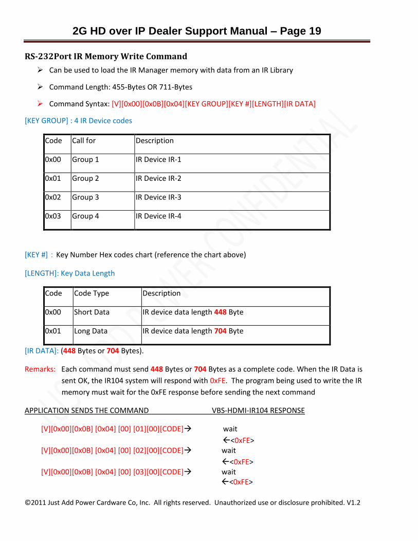
RS-232Port IR Memory Write Command
Can be used to load the IR Manager memory with data from an IR Library
Command Length: 455-Bytes OR 711-Bytes
Command Syntax: [V][0x00][0x0B][0x04][KEY GROUP][KEY #][LENGTH][IR DATA]
[KEY GROUP] : 4 IR Device codes
Code Call for Description
0x00 Group 1 IR Device IR-1
0x01 Group 2 IR Device IR-2
0x02 Group 3 IR Device IR-3
0x03 Group 4 IR Device IR-4
[KEY #]:Key Number Hex codes chart (reference the chart above)
[LENGTH]: Key Data Length
Code Code Type Description
0x00 Short Data IR device data length 448 Byte
0x01 Long Data IR device data length 704 Byte
[IR DATA]: (448 Bytes or 704 Bytes).
Remarks: Each command must send 448 Bytes or 704 Bytes as a complete code. When the IR Data is
sent OK, the IR104 system will respond with 0xFE. The program being used to write the IR
memory must wait for the 0xFE response before sending the next command
APPLICATION SENDS THE COMMAND VBS-HDMI-IR104 RESPONSE
[V][0x00][0x0B] [0x04] [00] [01][00][CODE] wait
<0xFE> [V][0x00][0x0B] [0x04] [00] [02][00][CODE] wait
<0xFE> [V][0x00][0x0B] [0x04] [00] [03][00][CODE] wait
<0xFE>
2G HD over IP Dealer Support Manual – Page 20
©2011 Just Add Power Cardware Co, Inc. All rights reserved. Unauthorized use or disclosure prohibited. V1.2
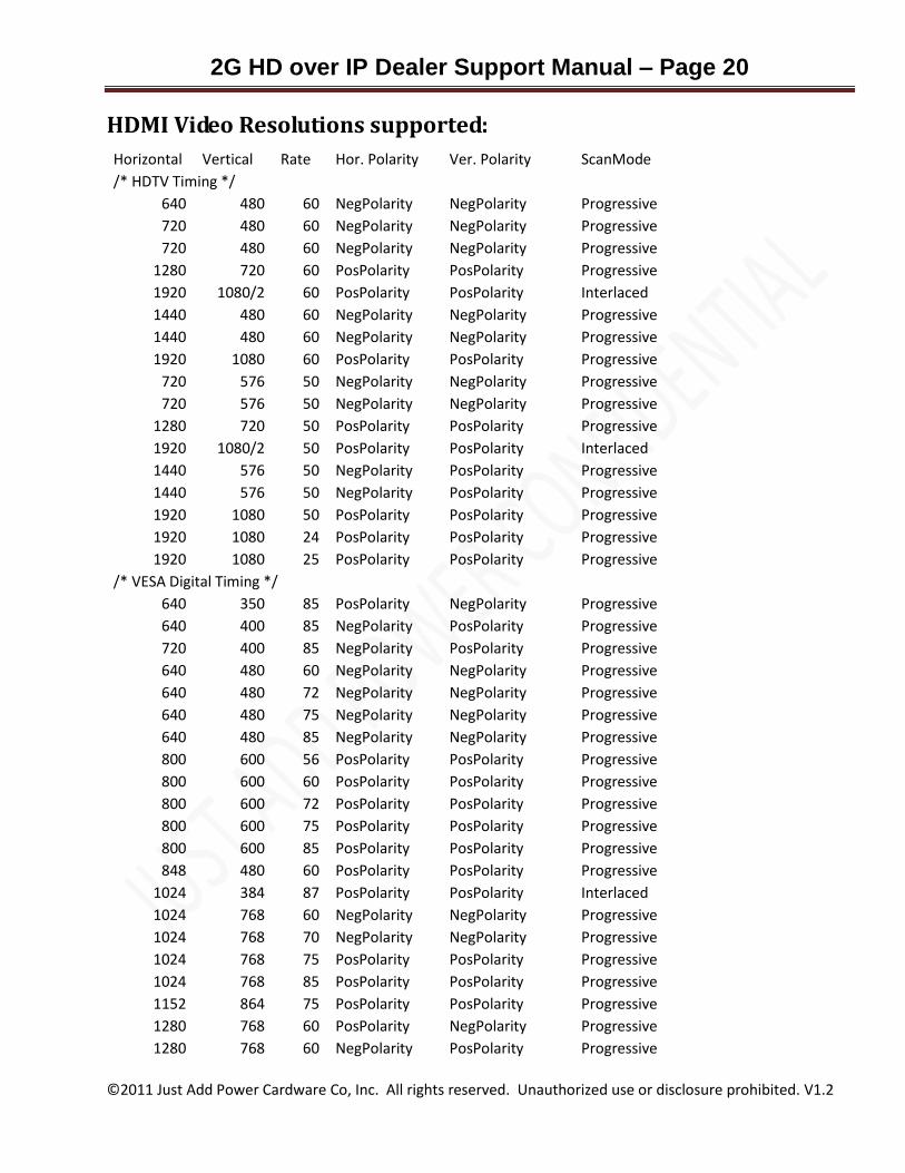
HDMI Video Resolutions supported:
Horizontal Vertical Rate Hor. Polarity Ver. Polarity ScanMode
/* HDTV Timing */ 640 480 60 NegPolarity NegPolarity Progressive
720 480 60 NegPolarity NegPolarity Progressive
720 480 60 NegPolarity NegPolarity Progressive
1280 720 60 PosPolarity PosPolarity Progressive
1920 1080/2 60 PosPolarity PosPolarity Interlaced
1440 480 60 NegPolarity NegPolarity Progressive
1440 480 60 NegPolarity NegPolarity Progressive
1920 1080 60 PosPolarity PosPolarity Progressive
720 576 50 NegPolarity NegPolarity Progressive
720 576 50 NegPolarity NegPolarity Progressive
1280 720 50 PosPolarity PosPolarity Progressive
1920 1080/2 50 PosPolarity PosPolarity Interlaced
1440 576 50 NegPolarity PosPolarity Progressive
1440 576 50 NegPolarity PosPolarity Progressive
1920 1080 50 PosPolarity PosPolarity Progressive
1920 1080 24 PosPolarity PosPolarity Progressive
1920 1080 25 PosPolarity PosPolarity Progressive
/* VESA Digital Timing */
640 350 85 PosPolarity NegPolarity Progressive
640 400 85 NegPolarity PosPolarity Progressive
720 400 85 NegPolarity PosPolarity Progressive
640 480 60 NegPolarity NegPolarity Progressive
640 480 72 NegPolarity NegPolarity Progressive
640 480 75 NegPolarity NegPolarity Progressive
640 480 85 NegPolarity NegPolarity Progressive
800 600 56 PosPolarity PosPolarity Progressive
800 600 60 PosPolarity PosPolarity Progressive
800 600 72 PosPolarity PosPolarity Progressive
800 600 75 PosPolarity PosPolarity Progressive
800 600 85 PosPolarity PosPolarity Progressive
848 480 60 PosPolarity PosPolarity Progressive
1024 384 87 PosPolarity PosPolarity Interlaced
1024 768 60 NegPolarity NegPolarity Progressive
1024 768 70 NegPolarity NegPolarity Progressive
1024 768 75 PosPolarity PosPolarity Progressive
1024 768 85 PosPolarity PosPolarity Progressive
1152 864 75 PosPolarity PosPolarity Progressive
1280 768 60 PosPolarity NegPolarity Progressive
1280 768 60 NegPolarity PosPolarity Progressive
2G HD over IP Dealer Support Manual – Page 21
©2011 Just Add Power Cardware Co, Inc. All rights reserved. Unauthorized use or disclosure prohibited. V1.2
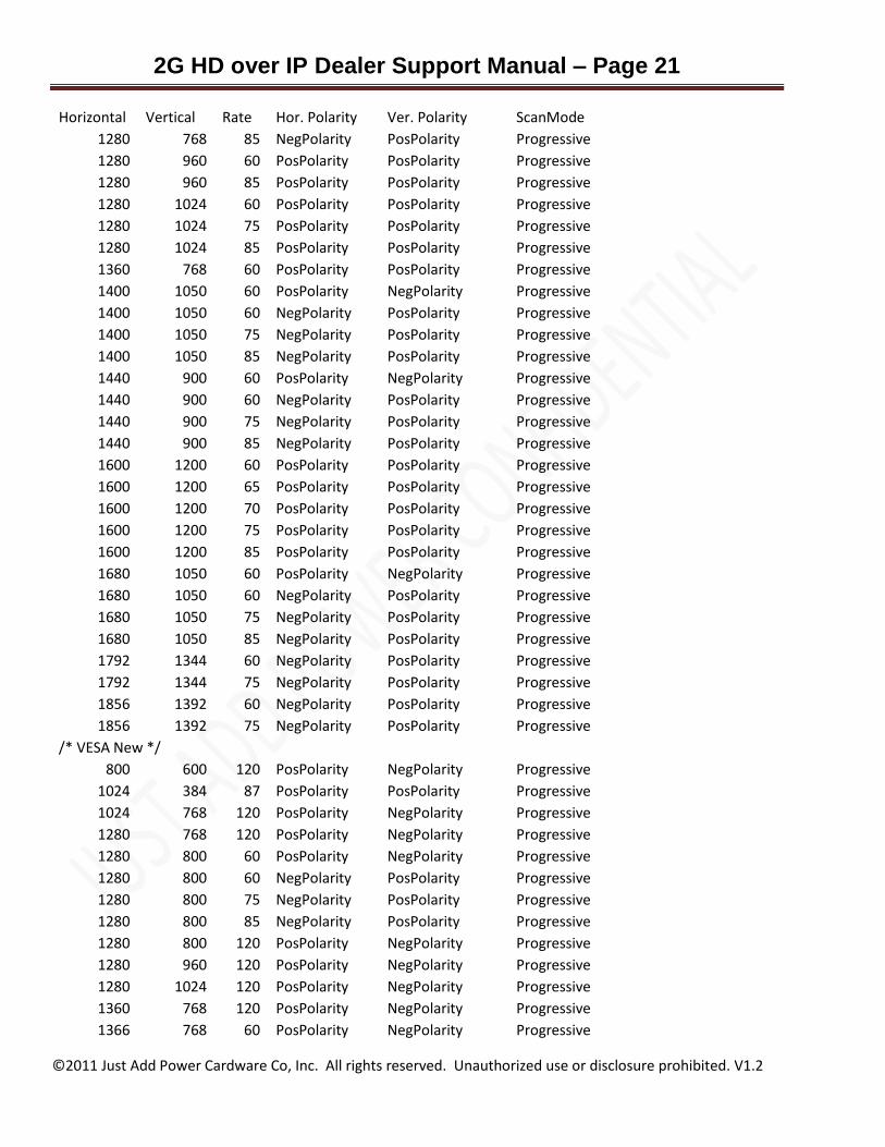
Horizontal Vertical Rate Hor. Polarity Ver. Polarity ScanMode
1280 768 85 NegPolarity PosPolarity Progressive
1280 960 60 PosPolarity PosPolarity Progressive
1280 960 85 PosPolarity PosPolarity Progressive
1280 1024 60 PosPolarity PosPolarity Progressive
1280 1024 75 PosPolarity PosPolarity Progressive
1280 1024 85 PosPolarity PosPolarity Progressive
1360 768 60 PosPolarity PosPolarity Progressive
1400 1050 60 PosPolarity NegPolarity Progressive
1400 1050 60 NegPolarity PosPolarity Progressive
1400 1050 75 NegPolarity PosPolarity Progressive
1400 1050 85 NegPolarity PosPolarity Progressive
1440 900 60 PosPolarity NegPolarity Progressive
1440 900 60 NegPolarity PosPolarity Progressive
1440 900 75 NegPolarity PosPolarity Progressive
1440 900 85 NegPolarity PosPolarity Progressive
1600 1200 60 PosPolarity PosPolarity Progressive
1600 1200 65 PosPolarity PosPolarity Progressive
1600 1200 70 PosPolarity PosPolarity Progressive
1600 1200 75 PosPolarity PosPolarity Progressive
1600 1200 85 PosPolarity PosPolarity Progressive
1680 1050 60 PosPolarity NegPolarity Progressive
1680 1050 60 NegPolarity PosPolarity Progressive
1680 1050 75 NegPolarity PosPolarity Progressive
1680 1050 85 NegPolarity PosPolarity Progressive
1792 1344 60 NegPolarity PosPolarity Progressive
1792 1344 75 NegPolarity PosPolarity Progressive
1856 1392 60 NegPolarity PosPolarity Progressive
1856 1392 75 NegPolarity PosPolarity Progressive
/* VESA New */ 800 600 120 PosPolarity NegPolarity Progressive
1024 384 87 PosPolarity PosPolarity Progressive
1024 768 120 PosPolarity NegPolarity Progressive
1280 768 120 PosPolarity NegPolarity Progressive
1280 800 60 PosPolarity NegPolarity Progressive
1280 800 60 NegPolarity PosPolarity Progressive
1280 800 75 NegPolarity PosPolarity Progressive
1280 800 85 NegPolarity PosPolarity Progressive
1280 800 120 PosPolarity NegPolarity Progressive
1280 960 120 PosPolarity NegPolarity Progressive
1280 1024 120 PosPolarity NegPolarity Progressive
1360 768 120 PosPolarity NegPolarity Progressive
1366 768 60 PosPolarity NegPolarity Progressive

2G HD over IP Dealer Support Manual – Page 22
©2011 Just Add Power Cardware Co, Inc. All rights reserved. Unauthorized use or disclosure prohibited. V1.2
Horizontal Vertical Rate Hor. Polarity Ver. Polarity ScanMode
1366 768 60 PosPolarity PosPolarity Progressive
1400 1050 120 PosPolarity NegPolarity Progressive
1440 900 120 PosPolarity NegPolarity Progressive
1600 900 60 PosPolarity NegPolarity Progressive
1920 1080 60 PosPolarity PosPolarity Progressive
/* VESA CVT Timing */ 640 480 50 NegPolarity PosPolarity Progressive
640 480 60 NegPolarity PosPolarity Progressive
640 480 75 NegPolarity PosPolarity Progressive
640 480 85 NegPolarity PosPolarity Progressive
640 480 60 PosPolarity NegPolarity Progressive
800 600 50 NegPolarity PosPolarity Progressive
800 600 60 NegPolarity PosPolarity Progressive
800 600 75 NegPolarity PosPolarity Progressive
800 600 85 NegPolarity PosPolarity Progressive
800 600 60 PosPolarity NegPolarity Progressive
1024 768 50 NegPolarity PosPolarity Progressive
1024 768 60 NegPolarity PosPolarity Progressive
1024 768 75 NegPolarity PosPolarity Progressive
1024 768 85 NegPolarity PosPolarity Progressive
1024 768 60 PosPolarity NegPolarity Progressive
1280 960 50 NegPolarity PosPolarity Progressive
1280 960 60 NegPolarity PosPolarity Progressive
1280 960 75 NegPolarity PosPolarity Progressive
1280 960 85 NegPolarity PosPolarity Progressive
1280 960 60 PosPolarity NegPolarity Progressive
1400 1050 50 NegPolarity PosPolarity Progressive
1400 1050 60 PosPolarity NegPolarity Progressive
1600 1200 50 NegPolarity PosPolarity Progressive
1600 1200 60 NegPolarity PosPolarity Progressive
1600 1200 75 NegPolarity PosPolarity Progressive
1600 1200 85 NegPolarity PosPolarity Progressive
1600 1200 60 PosPolarity NegPolarity Progressive
1280 1024 50 NegPolarity PosPolarity Progressive
1280 1024 60 NegPolarity PosPolarity Progressive
1280 1024 75 NegPolarity PosPolarity Progressive
1280 1024 85 NegPolarity PosPolarity Progressive
1280 1024 60 PosPolarity NegPolarity Progressive
1280 768 50 NegPolarity PosPolarity Progressive
1280 768 60 PosPolarity NegPolarity Progressive
848 480 50 NegPolarity PosPolarity Progressive
848 480 60 NegPolarity PosPolarity Progressive
2G HD over IP Dealer Support Manual – Page 23
©2011 Just Add Power Cardware Co, Inc. All rights reserved. Unauthorized use or disclosure prohibited. V1.2
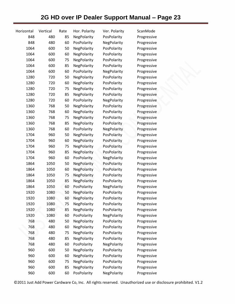
Horizontal Vertical Rate Hor. Polarity Ver. Polarity ScanMode
848 480 85 NegPolarity PosPolarity Progressive
848 480 60 PosPolarity NegPolarity Progressive
1064 600 50 NegPolarity PosPolarity Progressive
1064 600 60 NegPolarity PosPolarity Progressive
1064 600 75 NegPolarity PosPolarity Progressive
1064 600 85 NegPolarity PosPolarity Progressive
1064 600 60 PosPolarity NegPolarity Progressive
1280 720 50 NegPolarity PosPolarity Progressive
1280 720 60 NegPolarity PosPolarity Progressive
1280 720 75 NegPolarity PosPolarity Progressive
1280 720 85 NegPolarity PosPolarity Progressive
1280 720 60 PosPolarity NegPolarity Progressive
1360 768 50 NegPolarity PosPolarity Progressive
1360 768 60 NegPolarity PosPolarity Progressive
1360 768 75 NegPolarity PosPolarity Progressive
1360 768 85 NegPolarity PosPolarity Progressive
1360 768 60 PosPolarity NegPolarity Progressive
1704 960 50 NegPolarity PosPolarity Progressive
1704 960 60 NegPolarity PosPolarity Progressive
1704 960 75 NegPolarity PosPolarity Progressive
1704 960 85 NegPolarity PosPolarity Progressive
1704 960 60 PosPolarity NegPolarity Progressive
1864 1050 50 NegPolarity PosPolarity Progressive
1864 1050 60 NegPolarity PosPolarity Progressive
1864 1050 75 NegPolarity PosPolarity Progressive
1864 1050 85 NegPolarity PosPolarity Progressive
1864 1050 60 PosPolarity NegPolarity Progressive
1920 1080 50 NegPolarity PosPolarity Progressive
1920 1080 60 NegPolarity PosPolarity Progressive
1920 1080 75 NegPolarity PosPolarity Progressive
1920 1080 85 NegPolarity PosPolarity Progressive
1920 1080 60 PosPolarity NegPolarity Progressive
768 480 50 NegPolarity PosPolarity Progressive
768 480 60 NegPolarity PosPolarity Progressive
768 480 75 NegPolarity PosPolarity Progressive
768 480 85 NegPolarity PosPolarity Progressive
768 480 60 PosPolarity NegPolarity Progressive
960 600 50 NegPolarity PosPolarity Progressive
960 600 60 NegPolarity PosPolarity Progressive
960 600 75 NegPolarity PosPolarity Progressive
960 600 85 NegPolarity PosPolarity Progressive
960 600 60 PosPolarity NegPolarity Progressive
2G HD over IP Dealer Support Manual – Page 24
©2011 Just Add Power Cardware Co, Inc. All rights reserved. Unauthorized use or disclosure prohibited. V1.2
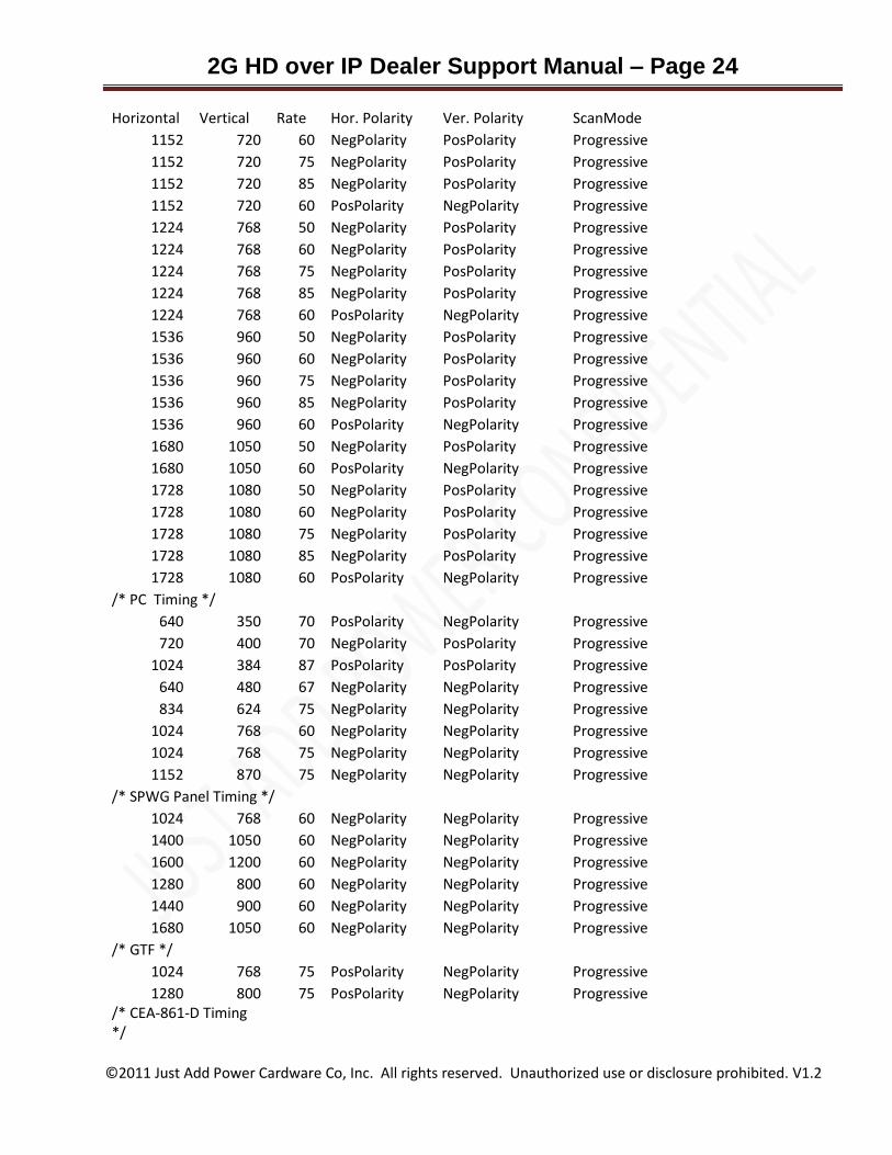
Horizontal Vertical Rate Hor. Polarity Ver. Polarity ScanMode
1152 720 60 NegPolarity PosPolarity Progressive
1152 720 75 NegPolarity PosPolarity Progressive
1152 720 85 NegPolarity PosPolarity Progressive
1152 720 60 PosPolarity NegPolarity Progressive
1224 768 50 NegPolarity PosPolarity Progressive
1224 768 60 NegPolarity PosPolarity Progressive
1224 768 75 NegPolarity PosPolarity Progressive
1224 768 85 NegPolarity PosPolarity Progressive
1224 768 60 PosPolarity NegPolarity Progressive
1536 960 50 NegPolarity PosPolarity Progressive
1536 960 60 NegPolarity PosPolarity Progressive
1536 960 75 NegPolarity PosPolarity Progressive
1536 960 85 NegPolarity PosPolarity Progressive
1536 960 60 PosPolarity NegPolarity Progressive
1680 1050 50 NegPolarity PosPolarity Progressive
1680 1050 60 PosPolarity NegPolarity Progressive
1728 1080 50 NegPolarity PosPolarity Progressive
1728 1080 60 NegPolarity PosPolarity Progressive
1728 1080 75 NegPolarity PosPolarity Progressive
1728 1080 85 NegPolarity PosPolarity Progressive
1728 1080 60 PosPolarity NegPolarity Progressive
/* PC Timing */ 640 350 70 PosPolarity NegPolarity Progressive
720 400 70 NegPolarity PosPolarity Progressive
1024 384 87 PosPolarity PosPolarity Progressive
640 480 67 NegPolarity NegPolarity Progressive
834 624 75 NegPolarity NegPolarity Progressive
1024 768 60 NegPolarity NegPolarity Progressive
1024 768 75 NegPolarity NegPolarity Progressive
1152 870 75 NegPolarity NegPolarity Progressive
/* SPWG Panel Timing */ 1024 768 60 NegPolarity NegPolarity Progressive
1400 1050 60 NegPolarity NegPolarity Progressive
1600 1200 60 NegPolarity NegPolarity Progressive
1280 800 60 NegPolarity NegPolarity Progressive
1440 900 60 NegPolarity NegPolarity Progressive
1680 1050 60 NegPolarity NegPolarity Progressive
/* GTF */ 1024 768 75 PosPolarity NegPolarity Progressive
1280 800 75 PosPolarity NegPolarity Progressive /* CEA-861-D Timing */
2G HD over IP Dealer Support Manual – Page 25
©2011 Just Add Power Cardware Co, Inc. All rights reserved. Unauthorized use or disclosure prohibited. V1.2
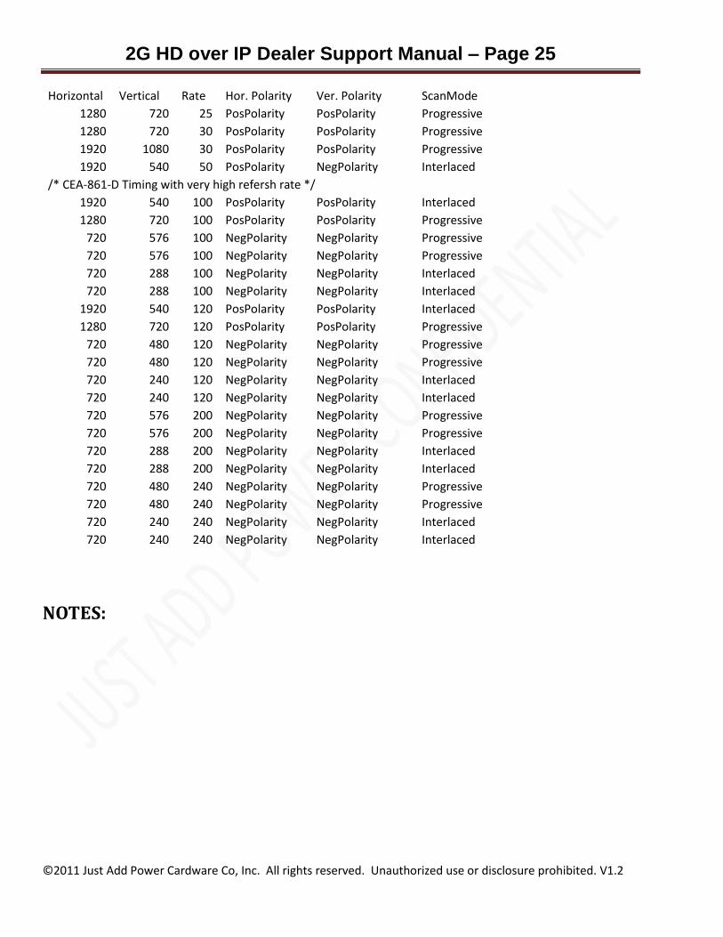
Horizontal Vertical Rate Hor. Polarity Ver. Polarity ScanMode
1280 720 25 PosPolarity PosPolarity Progressive
1280 720 30 PosPolarity PosPolarity Progressive
1920 1080 30 PosPolarity PosPolarity Progressive
1920 540 50 PosPolarity NegPolarity Interlaced
/* CEA-861-D Timing with very high refersh rate */ 1920 540 100 PosPolarity PosPolarity Interlaced
1280 720 100 PosPolarity PosPolarity Progressive
720 576 100 NegPolarity NegPolarity Progressive
720 576 100 NegPolarity NegPolarity Progressive
720 288 100 NegPolarity NegPolarity Interlaced
720 288 100 NegPolarity NegPolarity Interlaced
1920 540 120 PosPolarity PosPolarity Interlaced
1280 720 120 PosPolarity PosPolarity Progressive
720 480 120 NegPolarity NegPolarity Progressive
720 480 120 NegPolarity NegPolarity Progressive
720 240 120 NegPolarity NegPolarity Interlaced
720 240 120 NegPolarity NegPolarity Interlaced
720 576 200 NegPolarity NegPolarity Progressive
720 576 200 NegPolarity NegPolarity Progressive
720 288 200 NegPolarity NegPolarity Interlaced
720 288 200 NegPolarity NegPolarity Interlaced
720 480 240 NegPolarity NegPolarity Progressive
720 480 240 NegPolarity NegPolarity Progressive
720 240 240 NegPolarity NegPolarity Interlaced
720 240 240 NegPolarity NegPolarity Interlaced
NOTES: