deaerating feedwater heaters165.189.64.111/documents/industry services/forms/boilers/2012-4... ·...
TRANSCRIPT

Deaerating Feedwater Heaters
Bob Grant Machinery Breakdown Risk Engineer

This presentation is for informational purposes only and has an edition date of October 2011. This presentation is necessarily general in content and intended to provide an overview of certain aspects of deaerating feedwater heaters. No liability is assumed by reason of the information this document contains.
Chubb refers to the insurers of the Chubb Group of Insurance Companies. Coverage may not be available in all jurisdictions. This presentation is the property of Chubb. Any use of this presentations without Chubb’s prior, written consent is prohibited.

Bob Grant – Background
1972 – 1978 Boiler Technician U.S. Navy, USS Home, CG-30
1978 – 1980 Boiler Technician Instructor U.S. Navy, NTC Great Lakes, IL
1980 – 1982 Utilities/Boiler Operator Abbott Laboratories
1982 – 1988 Propulsion Engineering Instructor College of Lake County / Naval Training School
1988 – 2000 Loss Prevention Consultant / Boiler Inspector FM Global , Factory Mutual Engineering
2000 – 2008 Senior Boiler and Machinery Consultant Arise Incorporated
2008 – Present Machinery Breakdown Risk Engineer Chubb Group of Insurance Companies

Objectives
● Purpose ● Location ● Type ● Design ● Process ● Components ● Problems ● Solutions ● Preventative Maintenance

Purpose
Basic purposes of a Deaerating Feedwater Heater ● Removes air and non-condensable gases
(to deaerate) ● Acts as a reservoir for available feedwater
(to store) ● Increases boiler plant efficiency when steam is used
(to preheat) ● Provides a positive suction head for the pumps

Purpose
Removes non-condensable gases ● Removes oxygen, carbon dioxide, and other
non-condensable gases ● When heated in boiler systems, carbon dioxide (CO2)
and oxygen (O2) are released as gases and combine with water (H2O) to form carbonic acid (H2CO3)
CO2 + O2 + H2O → H2CO3
● Carbonic acid (H2CO3) causes corrosion of metals in the boiler

Purpose
Acts as a reservoir for available feedwater

Increases boiler plant efficiency
Purpose
Source: Low Pressure Boilers Textbook, 3rd Edition, 2009, American Technician Publishers, Inc., Homewood, IL, ISBN 978-0-8269-4358-3

Purpose
Source: NACE Standard SP0590-2007, National Association of Corrosion Engineers, ISBN 1-57590-0111-4, 2007, NACE International
Provides a net positive suction head for the feedwater pump

Location
Source: NACE Standard SP0590-2007, National Association of Corrosion Engineers, ISBN 1-57590-0111-4, 2007, NACE International

Type
Vertical deaerating heater with attached horizontal storage tank
Vertical deaerating heater with detached horizontal storage tank Vertical deaerating heater with storage in same shell Horizontal deaerating heater with storage in the same shell
Horizontal deaerating heater with detached horizontal storage

Vertical Deaerating Heater with Attached Storage Tank

Vertical Deaerating Heater with Detached Storage Tank

Vertical Deaerating Heater with Storage in the Same Shell

Horizontal Deaerating Heater with Storage in the Same Shell

Horizontal Deaerating Heater with Detached Storage Tank

Designs
● Horizontal-Mounted with Sprayer Valves ● Horizontal-Mounted with Sprayer Valves and Trays ● Vertical-Mounted with Trays ● Vertical-Mounted with Sprayer Valves and Atomizing
Valve

Sprayer valve
Design
Design
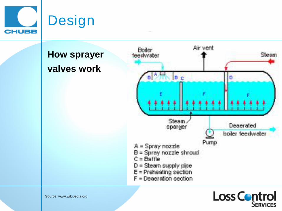
How sprayer valves work
Source: www.wikipedia.org

Design
How sprayer valves work

Trays
Design
Design
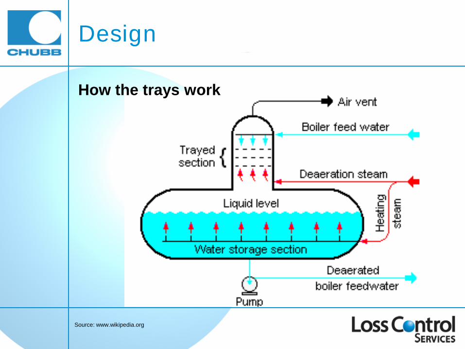
Source: www.wikipedia.org
How the trays work

Atomizing valve
Design
Source: Principles of Naval Engineering, NAVPERS 10788-B, Revision 1970, U.S. Government Printing Office, Washington, D.C., Stock No. 008-047-00127-4 / Catalog No. D208.112/:EN3/2/970.

How the atomizing valve works
Design
Source: Principles of Naval Engineering, NAVPERS 10788-B, Revision 1970, U.S. Government Printing Office, Washington, D.C., Stock No. 008-047-00127-4 / Catalog No. D208.112/:EN3/2/970.

Deaeration Process
How sprayer valves work
Source: www.wikipedia.org

Process: Sprayer Valves or Nozzles
Source: Navy Fireman Manual, NAVEDTRA 14104, 1992 Edition, Naval Education and Training, Professional Development and Technology Center, NAVSUP Logistics Tracking Number 0504-LP-026-7720
How sprayer valves or nozzles work (Components 1)

Process: Trays
Source: www.wikipedia.org

Process: Sprayer Valves and Trays
How sprayer valves and trays work

Process: Atomizing Valve
Source: Principles of Naval Engineering, NAVPERS 10788-B, Revision 1970, U.S. Government Printing Office, Washington, D.C., Stock No. 008-047-00127-4 / Catalog No. D208.112/:EN3/2/970.

Components
Source: Navy Fireman Manual, NAVEDTRA 14104, 1992 Edition, Naval Education and Training, Professional Development and Technology Center, NAVSUP Logistics Tracking Number 0504-LP-026-7720
Vertically-mounted heater with sprayer valves (Components 1)

Components
Source: Principles of Naval Engineering, NAVPERS 10788-B, Revision 1970, U.S. Government Printing Office, Washington, D.C., Stock No. 008-047-00127-4 / Catalog No. D208.112/:EN3/2/970.
Vertical deaerating heater with an atomizing valve (Components 3)

Problems
● Oxygen Corrosion ● Steam Erosion ● Cracking

Problem: Corrosion
Oxygen Corrosion ● Establish these issues
○ type of corrosion (local pitting or uniform) ○ location ○ any obvious data

Problem: Corrosion
● When heated in boiler systems, carbon dioxide (CO2) and oxygen (O2) are released as gases and combine with water (H2O) to form carbonic acid (H2CO3)
CO2 + O2 + H2O → H2CO3
● Carbonic acid (H2CO3) causes corrosion of metals in the boiler

Problem: Corrosion

Problem: Corrosion
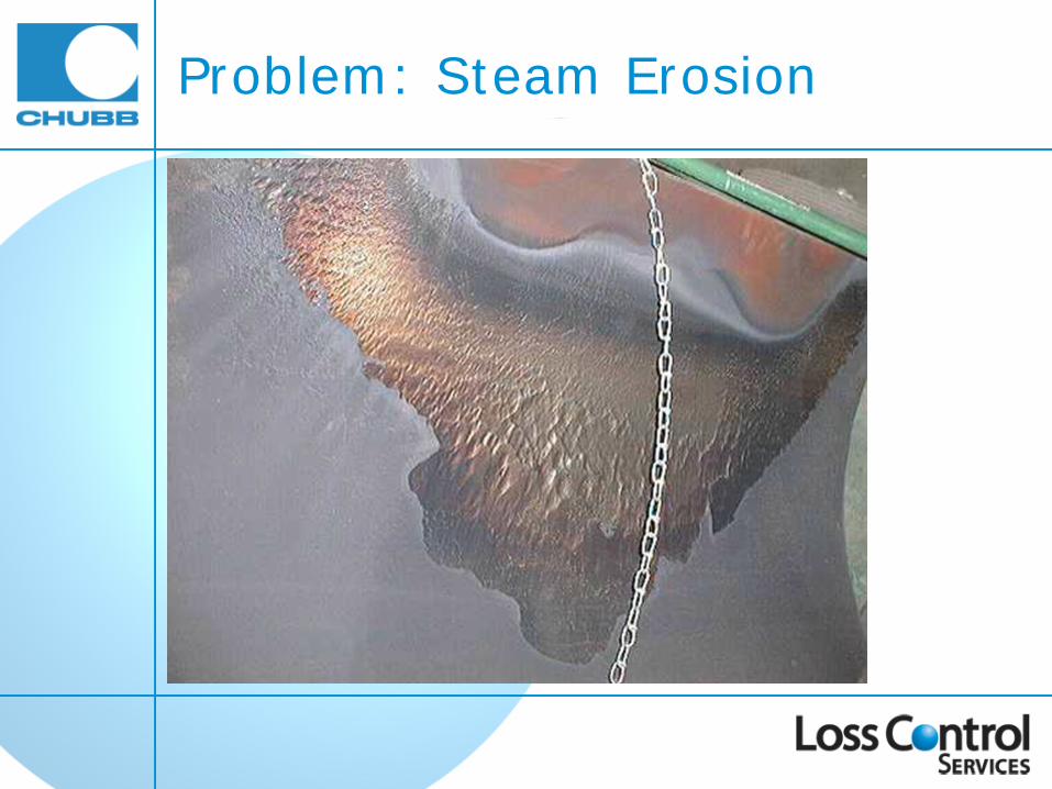
Problem: Steam Erosion

Problem: Steam Erosion

Problem: Steam Erosion
Source: NACE Standard SP0590-2007, National Association of Corrosion Engineers, ISBN 1-57590-0111-4, 2007, NACE International

Problem: Steam Erosion
Heater Section
Source: NACE Standard SP0590-2007, National Association of Corrosion Engineers, ISBN 1-57590-0111-4, 2007, NACE International

Problem: Cracking

Problem: Cracking

Solutions
● Corrosion Pitting – Welded Repair ● Steam Erosion – Welded Repair ● Cracking – Welded Repair

Solutions
IMPORTANT
Welded repairs must be performed by
a certified ‘R-STAMP’ welding repair concern

Corrosion – Welded Repair
Replacing sections of localized pitting

Erosion – Welded Repair

Cracking – Welded Repair

Preventative Maintenance
● Visual Inspection ● Maintenance

Preventative Maintenance Visual Inspection
Horizontally-mounted heater with sprayer valves and trays
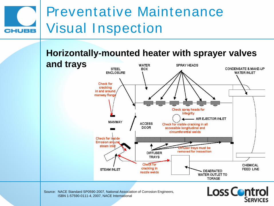
Preventative Maintenance Visual Inspection
Source: NACE Standard SP0590-2007, National Association of Corrosion Engineers, ISBN 1-57590-0111-4, 2007, NACE International
Horizontally-mounted heater with sprayer valves and trays

Preventative Maintenance Visual Inspection
Source: NACE Standard SP0590-2007, National Association of Corrosion Engineers, ISBN 1-57590-0111-4, 2007, NACE International
1. Vessel shell and head ○ Check for corrosion pitting ○ Check for indications of erosion ○ Check for debris

Visual Inspection Corrosion Pitting

Visual Inspection Corrosion Pitting Corrosion is normally found in the bottom of the vessel

Visual Inspection Steam Erosion

Visual Inspection Steam Erosion
Source: NACE Standard SP0590-2007, National Association of Corrosion Engineers, ISBN 1-57590-0111-4, 2007, NACE International

Visual Inspection Debris

Preventative Maintenance Visual Inspection
2. Tray Stack ○ Ensure that trays are neat and orderly ○ Ensure that hold-downs are firmly in place

Visual Inspection Tray Stack Upset trays

Visual Inspection Tray Stack Damaged trays

Visual Inspection Tray Stack Corroded trays

Preventative Maintenance Visual Inspection
3. Spray Valves ○ Spot check spray valves for proper adjustment ○ Look for any spray valves hanging open

Preventative Maintenance Visual Inspection Sprayer valve

Preventative Maintenance Visual Inspection
4. Nozzles ○ Check for cracked welds where the nozzles protrude
through the shell
Source: NACE Standard SP0590-2007, National Association of Corrosion Engineers, ISBN 1-57590-0111-4, 2007, NACE International

Preventative Maintenance Visual Inspection
5. Saddles and Supports (inside of vessel) ○ Check for cracked attachment welds to the vessel shell

Preventative Maintenance Visual Inspection Saddles / supports (outside of vessel)
Source: NACE Standard SP0590-2007, National Association of Corrosion Engineers, ISBN 1-57590-0111-4, 2007, NACE International

Preventative Maintenance Visual Inspection
6. Safety Valve ○ Most important fitting on the deaerating heater

Preventative Maintenance Visual Inspection

Preventative Maintenance Visual Inspection

Preventative Maintenance Visual Inspection
● The setting must be ≤ the MAWP of the vessel ● The capacity of the safety valve must be large enough
to discharge all of the steam from the deaerating feedwater heater when the safety valve opens

Preventative Maintenance Visual Inspection The setting and capacity of the safety valve is located on its rating plate
Note: All repairs of safety valves must be performed by a certified safety valve repair facility that carries a VR Stamp

Preventative Maintenance Visual Inspection
Safety Valve ○ When discharge piping is used in connection with a
safety valve, it must be adequately braced and must not place a strain on the valve
○ Drains are placed at the lower sections of the discharge piping to remove any condensate

Preventative Maintenance Visual Inspection
Safety valve discharge piping ● Discharge piping will be
≥ the safety valve discharge/outlet size

Preventative Maintenance Visual Inspection

Preventative Maintenance Visual Inspection

Preventative Maintenance Testing ● Deaerating feedwater heaters have come under
increasing scrutiny since the late 1980s when there were a few instances of the pressure vessel failing catastrophically with some loss of life
● The failures were examined by the National Association of Corrosion Engineers (NACE) and their findings formed the basis of NACE Standard SP0590-2007

Preventative Maintenance Testing ● NACE Standard SP0590-2007 contains
recommendations for the testing of Deaerating Feedwater Heaters
● Summary of recommendations: ○ Areas of Inspection ○ Methods of Inspection ○ Inspection Personnel ○ Vessel Condition Classification ○ Method of Reporting

NACE Standard SP0590-2007 Recommendation
Area of Inspection All internal welds are to be inspected, including nozzle welds, head seams, vessel shell seams, plug welds in spun heads, and internal surfaces corresponding to external weld attachments.

NACE Standard SP0590-2007 Recommendation

NACE Standard SP0590-2007 Recommendations
Method of Inspection Wet Fluorescent Magnetic Particle Testing (WFMT) along with visual inspection, is recommended for the inspection of all internal carbon steel welds, including nozzle welds, head-to-shell welds, and shell longitudinal and circumferential welds.

Testing Internal Welds
NACE Standard SP0590-2007 Recommendations
Source: NACE Standard SP0590-2007, National Association of Corrosion Engineers, ISBN 1-57590-0111-4, 2007, NACE International
NACE Standard SP0590-2007 Recommendations
Inspection Personnel All third party inspection personnel should be certified to a minimum of Level I per ASNT SNT-TC-1A. Personnel that interpret inspection results should be certified to a minimum of Level II. (WFMT)
NACE Standard SP0590-2007 Recommendations
Additional Recommendations In addition to WFMT examination of the welds, Ultrasonic Testing should be done on areas where excessive corrosion, erosion and/or pitting is noted; to determine if there is sufficient remaining wall thickness in the affected area to continue to operate at the current pressure rating of the equipment. Any relevant indications must be fully evaluated and repaired as necessary.

Corrosion Pitting

Corrosion Pitting

Steam Erosion
Source: NACE Standard SP0590-2007, National Association of Corrosion Engineers, ISBN 1-57590-0111-4, 2007, NACE International

Steam Erosion

Steam Erosion

NACE Standard SP0590-2007 Recommendations
Vessel Condition Classification At the conclusion of the inspection, each vessel should be assigned a classification based on the results of the inspection:
○ Category I No relevant discontinuities ○ Category II Discontinuities detected,
but repairs not required ○ Category III Discontinuities detected,
and weld repairs required

NACE Standard SP0590-2007 Recommendations
Method of Reporting Inspection reports are to be geared toward long-term trend analysis. Each report is to include a drawing of the vessel, with weld seam and nozzle locations, and the results of the inspection.

Deaerating Feedwater Heaters
Thank you