de oliveira freestanding nis , nina orlovskaya x porous ... · pdf files-1 freestanding nisx...
TRANSCRIPT
S-1
Freestanding NiSx Porous Film as Binder-Free Electrode for Mg-Ion Battery
Kun Liang†,#, Kyle Marcus†, ‡,#, Limin Guo†, Zhao Li‡, Le Zhou‡, Yilun Liǁ, Samuel T.
De Oliveira¶, Nina Orlovskaya¶, Yong-Ho Sohn‡ & Yang Yang†, ‡,*
†NanoScience Technology Center, University of Central Florida, Orlando, FL 32826,
United States
‡Department of Materials Science and Engineering, University of Central Florida,
Orlando, FL 32826, United States
ǁ Department of Chemistry, Rice University, 6100 Main Street, Houston, Texas 77005,
United States
¶Department of Mechanical and Aerospace Engineering, University of Central
Florida, Orlando, FL 32826, United States
*E-mail: [email protected]
Electronic Supplementary Material (ESI) for ChemComm.This journal is © The Royal Society of Chemistry 2017

S-2
Experimental section
Fabrication of NPL. The Ni deposit was obtained through electrochemical
deposition. In a typical process, 0.9 M NiSO4, 0.13 M NiCl2, and 0.5 M H3BO3 were
dissolved in distilled water. The solution was stirred for 60 min at room temperature.
A home-made two-electrode system with polished stainless steel foil as cathode and
Pt-coated titanium mesh as anode was employed to deposit Ni layer. The cathode
current density was set at 20 mA cm-2 to perform electrochemical deposition for 7 min.
The free-standing Ni layer can be obtained after removing the deposit from the
substrate.
After electrodeposition, electrochemical etching was carried out in the same
plating electrolyte. The free-standing Ni layer and polished stainless steel foil were
used as anode and cathode, respectively. The etching time was 30 s with an anodic
current density of 20 mA cm-2. Then, the porous nickel layer was produced after
electrochemical etching. Subsequent electrochemically anodic treatment was
performed at a current density of 20 mA cm-2 for 10 min in the electrolyte of 0.2 M
NH4F with 2 M deionized water in ethylene glycol. The samples were washed with
ethanol, deionized water for 3 times, then dried under air gas flow. Finally, NPL was
created by electrochemical deposition, etching and anodization.
Fabrication of Nickel sulfides NPL
To convert NiO NPL to NiSx NPL, the sulfuration was performed in a CVD
system with two heating zones. Briefly, S powder and NiO NPL were placed at the
upstream and down-stream side of the tube in different heating zones, respectively.

S-3
The tube was evacuated to a pressure of 50 mTorr for 10 min and purged with Ar to
remove the residual air. Then, the S powder zone and NPL zone were set to 150 and
275 oC, respectively. The reaction was performed for 30 min with Ar (100 sccm) as
carrier gas, followed by natural cooling.
Characterization. A ZEISS ULTRA 55 scanning electron microscope (SEM) and an
FEI Tecnai F30 high resolution transmission electron microscope (HRTEM) were
used to analyze the morphology and elemental mapping of the samples. X-ray
diffraction (XRD) curves were obtained using a PANalytical Empyrean
diffractometer (PANalytical B.V.) configured with a Cu Kα radiation. Raman spectra
were recorded with a Renishaw Raman RE01 scope (Renishaw, Inc.) using a 532 nm
excitation argon laser. X-ray photoelectron spectroscopy (XPS, Physical Electronics)
was employed to check chemical composition of the samples.
Electrochemical measurements. Type 2032 coin cells were assembled in a standard
two-electrode configuration with NiSx NPL as the working electrode, Mg foil as the
counter electrode, [AlCl3][PhMgCl]/tetrahydrofuran (THF) as electrolyte and Celgard
microporous membrane was employed as the separator. The area of the working
electrode was 1×1 cm2. Cyclic voltammetry (CV) was performed in a voltage window
of 0.2-2 V at a scan rate of 0.1 mV s-1. Galvanostatic charge/discharge curves were
recorded by Landt 2001A test system (Wuhan Land Electronic Co. Ltd., China). The
electrochemical impedance spectroscopy (EIS) was collected with frequency range
from 10 mHz to 100 kHz using a CHI 760E electrochemical station (CH Instruments,
USA).

S-4
Figure S1. (a) Top-view image of NPL after sulfuration. (b-c) Top-view and cross-
sectional images of NPL after sulfuration. The scale bars donate 1 μm.

S-5
SEM analysis
Compared with the SEM image in Figure S1b, there are morphology changes that
occur after cycling. It should be noted that there is no evidence showing the formation
of cracks on the electrode surface. However, aggregated particles with a diameter
ranging from 50-200 nm can be observed, caused by the large expansion and
shrinkage upon repeated magnesium insertion/extraction. Although the SEM images
show that there are morphology changes after cycling, the changes are not substantial,
giving the excellent cycling stability.
Figure S2. (a-d) SEM images after 100, 500, 1000 and 5000 cycles, respectively. The
scale bars donate 1 µm.

S-6
XRD and EDS analysis
The peaks of the Ni3S2 phase can be found at 21.8o, 37.9o, 49.7o, and 54.9o, while only
one peak of the NiS2 phase can be observed in the XRD pattern. It is noted that the
intensities of NiS2 and Ni3S2 were decreased sharply, suggesting that phases reacted
with Mg2+. Furthermore, this indicates that both of NiS2 and Ni3S2 are active materials
for magnesium-ion battery. An MgS peak can be found located at 30.1o and 34.7o,
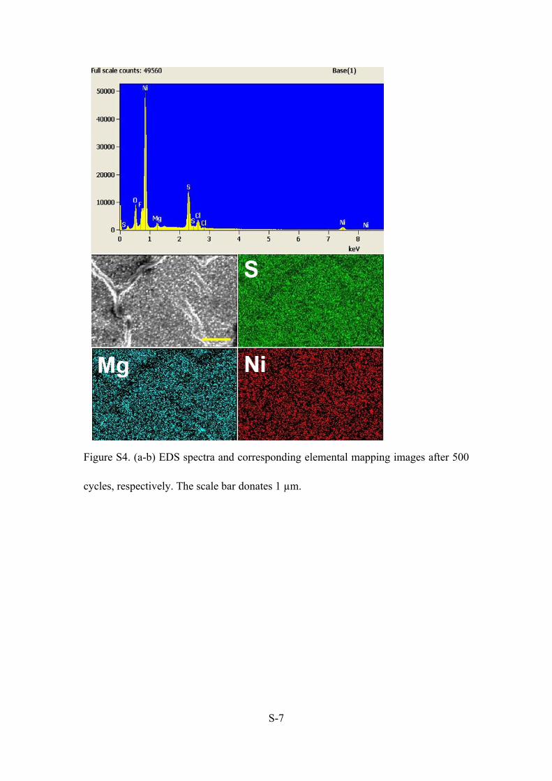
assigned to (111) and (200) planes, respectively.1,2 EDS and corresponding elemental
mappings after 500 and 5000 cycles were performed. From Figure S4a and S5a, Mg
peak can be observed in EDS spectra. Additionally, Mg is uniformly distributed
across the surface of the electrode in Figure S4b and S5b, therefore, the final product
after charging is MgS.
Figure S3. XRD image after 5000 cycles.
S-7
Figure S4. (a-b) EDS spectra and corresponding elemental mapping images after 500
cycles, respectively. The scale bar donates 1 µm.

S-8
Figure S5. (a-b) EDS spectra and corresponding elemental mapping images after 5000
cycles, respectively. The scale bar donates 1 µm.
S-9
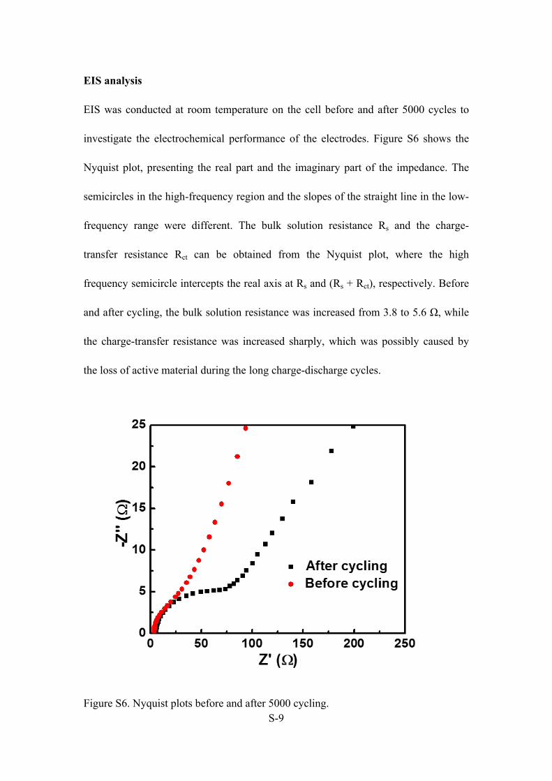
EIS analysis
EIS was conducted at room temperature on the cell before and after 5000 cycles to
investigate the electrochemical performance of the electrodes. Figure S6 shows the
Nyquist plot, presenting the real part and the imaginary part of the impedance. The
semicircles in the high-frequency region and the slopes of the straight line in the low-
frequency range were different. The bulk solution resistance Rs and the charge-
transfer resistance Rct can be obtained from the Nyquist plot, where the high
frequency semicircle intercepts the real axis at Rs and (Rs + Rct), respectively. Before
and after cycling, the bulk solution resistance was increased from 3.8 to 5.6 Ω, while
the charge-transfer resistance was increased sharply, which was possibly caused by
the loss of active material during the long charge-discharge cycles.
Figure S6. Nyquist plots before and after 5000 cycling.

S-10
Figure S7. Ragone plot of the NiSx NPL electrode. The compared MIB systems were
reported. 1-4 The volumetric energy density and power density are calculated based on
the specific capacity and the volume of the electrode.
Reference
S1. Wang, M., Li, X., Gao, M., Pan, H., Liu, Y., A Novel Synthesis of MgS and its
Application as Electrode Material for Lithium-Ion Batteries. J. Alloy Compd, 2014,
603, 158-166.
S2. Goo, N. H., Hirscher, M., Synthesis of the Nanocrystalline MgS and its
Interaction with Hydrogen. J. Alloy Compd, 2005, 404-406, 503-506.
S3. Zhang, R.; Mizuno, F.; Ling, C., Fullerenes: Non-Transition Metal Clusters as
Rechargeable Magnesium Battery Cathodes. Chem. Commun. 2014, 51 (6), 1108-

S-11
1111.
S4. Liang, Y.; Feng, R.; Yang, S.; Ma, H.; Liang, J.; Chen, J., Rechargeable Mg
Batteries with Graphene-like MoS2 Cathode and Ultrasmall Mg Nanoparticle Anode.
Adv. Mater. 2011, 23 (5), 640-643.
S5. Zhang, R.; Ling, C.; Mizuno, F., A Conceptual Magnesium Battery with
Ultrahigh Rate Capability. Chem. Commun. 2015, 51 (8), 1487-1490.
S6. NuLi, Y.; Yang, J.; Wang, J.; Li, Y., Electrochemical Intercalation of Mg2+ in
Magnesium Manganese Silicate and Its Application as High-Energy Rechargeable
Magnesium Battery Cathode. J. Phys. Chem. C 2009, 113 (28), 12594-12597.