de 00 einband - szwalnicze.com · the pfaff 5704 is a single needle, overlock sewing machine with...
TRANSCRIPT

INSTRUCTION MANUAL
296-12-18 606/002Betriebsanleitung engl. 06.09
This instruction manual applies to machines from the following serial numbers onwards:# 6 001 000
57045714
Industrial
®
57165742

This Instruction Manual is valid for all models and subclasses listed in the chapter "Specifications ".
The reprinting, copying or translation of PFAFF Instruction Manuals, whether in whole or in part, is only permitted with our previous authorization and with written reference to the source.
PFAFF Industriesysteme und Maschinen AG
Hans-Geiger-Str. 12 - IG Nord
D-67661 Kaiserslautern

Contents
Contents ................................................................................. Chapter - Page
1 Safety ........................................................................................................................... 1 - 1
1.01 Regulations ................................................................................................................... 1 - 11.02 General notes on safety ................................................................................................ 1 - 11.03 Safety symbols ............................................................................................................. 1 - 21.04 Important notes for the user ......................................................................................... 1 - 21.05 Notes for operating and technical staff ......................................................................... 1 - 31.05.01 Operating staff .............................................................................................................. 1 - 31.05.02 Technical staff ............................................................................................................... 1 - 31.06 Danger warnings ........................................................................................................... 1 - 4
2 Proper use.................................................................................................................... 2 - 1
3 Specifications .............................................................................................................. 3 - 1
3.01 General specifications ................................................................................................... 3 - 13.02 Specifications of the PFAFF 5704 ................................................................................. 3 - 23.03 Specifications of the PFAFF 5714 ................................................................................. 3 - 23.04 Specifications of the PFAFF 5716 ................................................................................. 3 - 33.05 Specifications of the PFAFF 5742 ................................................................................. 3 - 3
4 Disposal of the machine ............................................................................................. 4 - 1
5 Transport, packaging and storage ............................................................................. 5 - 1
5.01 Transport to the customer ............................................................................................ 5 - 15.02 Transport within the customer’s premises ................................................................... 5 - 15.03 Disposal of the packaging ............................................................................................. 5 - 15.04 Storage ......................................................................................................................... 5 - 1
6 Explanation of the symbols ........................................................................................ 6 - 1
7 Control elements ......................................................................................................... 7 - 1
7.01 Main switch .................................................................................................................. 7 - 17.02 Pedal ............................................................................................................................. 7 - 17.03 Balance wheel ............................................................................................................... 7 - 27.04 Sewing foot retracting lever .......................................................................................... 7 - 27.05 Cloth plate stop lever .................................................................................................... 7 - 37.06 Stop button for stitch length adjustment....................................................................... 7 - 37.07 Lever for setting the fullness ........................................................................................ 7 - 4
8 Mounting and commissioning the machine ............................................................. 8 - 1
8.01 Installation ..................................................................................................................... 8 - 18.01.01 Adjusting the table height ............................................................................................. 8 - 18.01.02 Table top drill hole plans (for mid-height assembly) ....................................................... 8 - 28.01.03 Table top cut-out (for mid-height assembly) .................................................................. 8 - 38.01.04 Sewing head support plate (for mid-height assembly) .................................................. 8 - 48.01.05 Table top drill hole plans (for assembly level with the table top) ................................... 8 - 58.01.06 Table top cut-out (for assembly level with the table top) ............................................... 8 - 6

Contents
Contents ................................................................................. Chapter - Page
8.01.07 Mounting the table top .................................................................................................. 8 - 78.01.08 Tightening the V-belt ..................................................................................................... 8 - 88.01.09 Fitting the top belt guard ............................................................................................... 8 - 88.01.10 Fitting the bottom belt guard. ........................................................................................ 8 - 98.01.11 Chain for securing the pedal .......................................................................................... 8 - 98.01.12 Mounting the reel stand ................................................................................................ 8 - 108.02 Commissioning ............................................................................................................. 8 - 118.03 Switching the machine on/off ....................................................................................... 8 - 11
9 Preparation .................................................................................................................. 9 - 1
9.01 Inserting the needle ...................................................................................................... 9 - 19.02 Threading the needle thread ......................................................................................... 9 - 19.02.01 Threading diagram for the PFAFF 5704 ......................................................................... 9 - 29.02.02 Threading diagram for the PFAFF 5714 ......................................................................... 9 - 29.02.03 Threading diagram for the PFAFF 5716 ......................................................................... 9 - 39.02.04 Threading diagram for the PFAFF 5742 ......................................................................... 9 - 39.03 Adjusting the stitch length ............................................................................................ 9 - 49.04 Adjusting the fullness .................................................................................................... 9 - 49.05 Adjusting the sewing foot pressure .............................................................................. 9 - 5
10 Care and maintenance .............................................................................................. 10 - 1
10.01 Maintenance intervals ................................................................................................. 10 - 110.02 Cleaning the machine .................................................................................................. 10 - 110.03 Cleaning the hook compartment ................................................................................. 10 - 210.04 Checking the oil level .................................................................................................. 10 - 210.05 Changing the oil .......................................................................................................... 10 - 310.06 Oiling the thread lubrication ........................................................................................ 10 - 410.07 Oiling the machine ...................................................................................................... 10 - 510.08 Changing the knife ...................................................................................................... 10 - 6
11 Adjustment ................................................................................................................ 11 - 1
11.01 Notes on adjustment................................................................................................... 11 - 111.02 Tools, gauges and other accessories .......................................................................... 11 - 111.03 Settings on the PFAFF 5704 ....................................................................................... 11 - 111.04 Settings on the PFAFF 5714 ....................................................................................... 11 - 211.05 Settings on the PFAFF 5716 ....................................................................................... 11 - 211.06 Settings on the PFAFF 5742 ....................................................................................... 11 - 2
12 Wearing parts ............................................................................................................ 12 - 1

Safety
1 - 1
1 Safety
1.01 Regulations
This machine is constructed in accordance with the European regulations indicated in theconformity and manufacturer's declarations.In addition to this instruction manual, please also observe all generally accepted, statutoryand other legal requirements, including those of the user's country, and the applicable pol-lution control regulations!The valid regulations of the regional social insurance society for occupational accidents orother supervisory authorities are to be strictly adhered to!
1.02 General notes on safety
● The machine must only be operated by adequately trained operators and only when theinstruction manual has been fully read and understood!
● All notices on safety and the instruction manual of the motor manufacturer are to be readbefore the machine is put into operation!
● All notes on the machine concerning danger and safety must be observed!
● The machine must be used for the purpose for which it is intended and must not beoperated without its safety devices; all regulations relevant to safety must be adhered to.
● When part sets are changed (e.g. needle, presser foot, needle plate or feed dog), duringthreading, when the workplace is left unattended and during maintenance work, themachine must be disconnected from the power supply by turning off the on/off switch orremoving the plug from the mains!
● Daily maintenance work must only be carried out by appropriately trained persons!
● Repairs and special maintenance work must only be carried out by qualified technicalstaff or persons with appropriate training!
● During maintenance or repairs on the pneumatic system the machine must bedisconnected from the compressed air supply! The only exception to this is whenadjustments or function checks are carried out by appropriately trained technical staff!
● Work on the electrical equipment must only be carried out by technical staff who arequalified to do so!
● Work on parts or equipment connected to the power supply is not permitted! The onlyexceptions to this are specified in regulations EN 50110.
● Conversion or modification of the machine must only be carried out under observation ofall relevant safety regulations!

Safety
1 - 2
● Only spare parts which have been approved by us are to be used for repairs! We drawspecial attention to the fact that spare parts and accessories not supplied by us have notbeen subjected to testing nor approval by us. Fitting and/or use of any such parts maycause negative changes to the design characteristics of the machine. We shall not ac-cept any liability for damage caused by the use of non-original parts.
1.03 Safety symbols
Danger!Special points to observe.
Danger of injury to operating or technical staff!
I
1.04 Important notes for the user
● This instruction manual belongs to the equipment of the machine and must be availableto the operating staff at all times.This instruction manual must be read before the machine is operated for the first time.
● Both operating and technical staff must be instructed on the safety devices of the mach-ine and on safe working methods.
● It is the duty of the user to operate the machine in perfect running order only.
● The user must ensure that none of the safety devices are removed nor put out of work-ing order.
● The user must ensure that only authorized persons operate and work on the machine.
For further information please refer to your PFAFF agency.
CautionDo not operate without finger guard and safety devices.Before threading, changing needle, cleaning etc. switchoff main switch.

Safety
1 - 3
1.05 Notes for operating and technical staff
1.05.01 Operating staff
Operating staff are the persons responsible for setting up, operating and cleaning the mach-ine and for removing any disturbances in the sewing area.
The operating staff are obliged to observe the following points, and must:
● always observe the notes on safety in this instruction manual!
● avoid using any working methods which adversely effect the safety of the machine!
● avoid wearing loose-fitting clothing or jewelry such as necklaces or rings!
● also ensure that only authorized persons are allowed near the danger area of themachine!
● immediately report to the user any changes to the machine that may affect its safety!
1.05.02 Technical staff
Technical staff are persons who have been trained in electrical engineering, electronics,pneumatics and mechanical engineering. They are responsible for lubricating, servicing,repairing and adjusting the machine.
The technical staff are obliged to observe the following points, and must:
● always observe the notes on safety in this instruction manual!
● switch off the on/off switch before carrying out adjustment and repair work and ensure itcannot be switched on again unintentionally!
● never work on parts or equipment still connected to the power supply! Exceptions to thisare only permissible according to regulations EN 50110;
● disconnected the machine from the compressed air supply when carrying outmaintenance or repair work on pneumatic equipment!Exceptions to this are only permissible for function checks;
● replace all safety covers after carrying out maintenance or repair work!
Safety
1 - 4
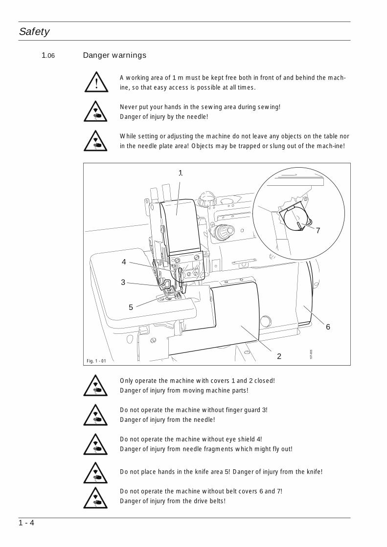
1.06 Danger warnings
A working area of 1 m must be kept free both in front of and behind the mach-ine, so that easy access is possible at all times.
Never put your hands in the sewing area during sewing!Danger of injury by the needle!
While setting or adjusting the machine do not leave any objects on the table norin the needle plate area! Objects may be trapped or slung out of the mach-ine!
Only operate the machine with covers 1 and 2 closed!Danger of injury from moving machine parts!
Do not operate the machine without finger guard 3!Danger of injury from the needle!
Do not operate the machine without eye shield 4!Danger of injury from needle fragments which might fly out!
Do not place hands in the knife area 5! Danger of injury from the knife!
Do not operate the machine without belt covers 6 and 7!Danger of injury from the drive belts!
Fig. 1 - 01
7
1
3
5
6
2
4

Proper use
2 - 1
2 Proper use
The PFAFF 5704 is a single needle, overlock sewing machine with differential bottom feedand is used for sewing closing and serging seams.
The PFAFF 5714 is a two needle, overlock sewing machine with differential bottom feed andis used for sewing closing and serging seams.
The PFAFF 5716 is a two needle, safety-stitch machine with differential bottom feed and isused for sewing closing seams.
The PFAFF 5742 is a two needle, two-thread chainstitch sewing machine with differentialbottom feed and is used for binding pocket pouches etc.
Any and all uses of this machine which have not been approved of by themanufacturer are considered to be inappropriate! The manufacturer cannot beheld liable for any damage caused by the inappropriate use of the machine! Theappropriate use of the machine includes the observance of all operational,adjustment, maintenance and repair measures required by the manufacturer!

Specifications
3 - 1
3 Specifications
3.01 General specifications ▲
Stitch type: ............................................................................................................ see tableNeedle system: .........................................................................................................DCx27Needle size: ........................................................................................ 65 – 130 Nm (#9-21)
Power supply: ........................................................... 220 V ± 10%, 50/60 Hz, single phasePower consumption: ..................................................................................... min. 0.37 kVAElectrical power rating: ......................................................... see motor identification plateFuse protection: .................................................................... see motor identification plate
Noise data:Noise emission level at workplaceAt a speed of 4800 spm: ........................................................................... Lpa = 74.5 dB(A)■
(Noise measurement in accordance with DIN 45 635-48-B-1, ISO 11204, ISO 3744, ISO 4871)
Sewing head dimensions:Length: ...................................................................................................... approx. 300 mmWidth: ....................................................................................................... approx. 370 mmHeight: ...................................................................................................... approx. 250 mm
Standard base dimensions:Length: .................................................................................................... approx. 1060 mmWidth: ....................................................................................................... approx. 600 mmHeight: ...................................................................................................... approx. 820 mm
Packaging dimensions (sewing head only):Length: ...................................................................................................... approx. 478 mmWidth: ....................................................................................................... approx. 400 mmHeight: ...................................................................................................... approx. 355 mm
Gross weight of sewing head (with packaging): .......................................... approx. 45 kilos
▲ Subject to alterations■ KpA = 2,5 dB
Specifications
3 - 2
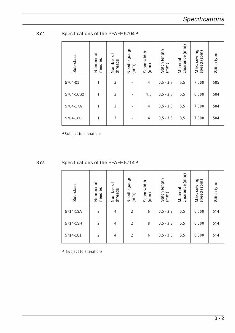
3.02 Specifications of the PFAFF 5704 ▲
▲ Subject to alterations
5704-01 1 3 - 4 0,5 - 3,8 5,5 7.000 505
5704-16S2 1 3 - 1,5 0,5 - 3,8 5,5 6.500 504
5704-17A 1 3 - 4 0,5 - 3,8 5,5 7.000 504
5704-180 1 3 - 4 0,5 - 3,8 3,5 7.000 504
Su
b-c
lass
Nu
mb
er o
fn
eed
les
Nu
mb
er o
fth
read
s
Nee
dle
gau
ge
(mm
)
Sea
m w
idth
(mm
)
Sti
tch
len
gth
(mm
)
Mat
eria
lcl
eara
nce
(mm
)
Max
. sew
ing
spee
d (
spm
)
Sti
tch
typ
e
3.03 Specifications of the PFAFF 5714 ▲
▲ Subject to alterations
5714-13A 2 4 2 6 0,5 - 3,8 5,5 6.500 514
5714-13H 2 4 2 8 0,5 - 3,8 5,5 6.500 514
5714-181 2 4 2 6 0,5 - 3,8 5,5 6.500 514
Su
b-c
lass
Nu
mb
er o
fn
eed
les
Nu
mb
er o
fth
read
s
Nee
dle
gau
ge
(mm
)
Sea
m w
idth
(mm
)
Sti
tch
len
gth
(mm
)
Mat
eria
lcl
eara
nce
(mm
)
Max
. sew
ing
spee
d (
spm
)
Sti
tch
typ
e
Specifications
3 - 3
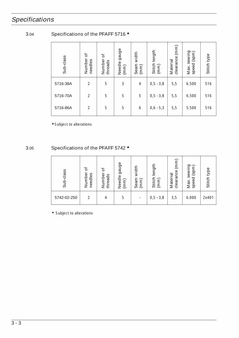
3.04 Specifications of the PFAFF 5716 ▲
▲ Subject to alterations
5716-38A 2 5 3 4 0,5 - 3,8 5,5 6.500 516
5716-70A 2 5 5 5 0,5 - 3,8 5,5 6.500 516
5716-86A 2 5 5 6 0,6 - 5,3 5,5 5.500 516
Su
b-c
lass
Nu
mb
er o
fn
eed
les
Nu
mb
er o
fth
read
s
Nee
dle
gau
ge
(mm
)
Sea
m w
idth
(mm
)
Sti
tch
len
gth
(mm
)
Mat
eria
lcl
eara
nce
(mm
)
Max
. sew
ing
spee
d (
spm
)
Sti
tch
typ
e
3.05 Specifications of the PFAFF 5742 ▲
▲ Subject to alterations
5742-02-250 2 4 5 - 0,5 - 3,8 3,5 6.000 2x401
Su
b-c
lass
Nu
mb
er o
fn
eed
les
Nu
mb
er o
fth
read
s
Nee
dle
gau
ge
(mm
)
Sea
m w
idth
(mm
)
Sti
tch
len
gth
(mm
)
Mat
eria
lcl
eara
nce
(mm
)
Max
. sew
ing
spee
d (
spm
)
Sti
tch
typ
e

Disposal of machine
4 - 1
4 Disposal of machine
● The proper disposal of the machine is the responsibility of the customer.
● The materials used in the machines are steel, aluminium, brass and various plastics.The electrical equipment consists of plastics and copper.
● The machine is to be disposed of in accordance with the locally valid environmentalprotection regulations. If necessary, a specialist is to be commissioned.
Special care is to be taken that parts soiled with lubricants are separatelydisposed of in accordance with the locally valid pollution control regulations!

Transport, packaging and storage
5 - 1
5 Transport, packaging and storage
5.01 Transport to the customer’s premises
The machines are delivered completely packed.
5.02 Transport within the customer’s premises
The manufacturer bears no liability for transport within the customer’s premises or to the in-dividual locations of use. Make sure that the machines are always transported upright.
5.03 Disposal of the packaging
The packaging of these machines consists of paper, cardboard and VCE fiber. The properdisposal of the packaging is the responsibility of the customer.
5.04 Storage
The machine can be stored for up to 6 months if not in use. During this time it should beprotected from dust and moisture.For longer storage the individual parts of the machine, especially the moving parts, must beprotected from corrosion, e.g. by a film of oil.

Explanation of the symbols
6 - 1
6 Explanation of the symbols
In the following section of this Instruction Manual, certain tasks or important pieces ofinformation are accentuated by symbols.The symbols used have the following meanings:
Note, information
Cleaning, care
Lubrication, greasing
Servicing, repairing, adjustment, maintenance(only to be carried out by specialist personnel)
Control elements
7 - 1
7 Control elements
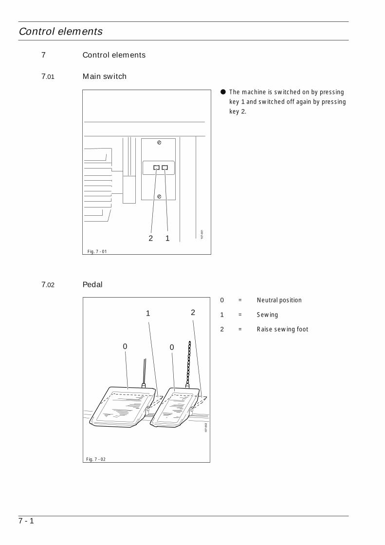
7.01 Main switch
● The machine is switched on by pressingkey 1 and switched off again by pressingkey 2.
Fig. 7 - 01
1
7.02 Pedal
0 = Neutral position
1 = Sewing
2 = Raise sewing foot
Fig. 7 - 02
2
1 2
0 0

Control elements
7 - 2
7.03 Balance wheel
● The needle bar is adjusted manually byturning the balance wheel 1 in thedirection of the arrow.
● If the stop button for stitch lengthadjustment is pressed at the same time,by turning balance wheel 1 the stitchlength is altered, see also Chapter 7.06
Stop button for stitch length
adjustment and Chapter 9.03 Adjusting
the stitch length.
Fig. 7 - 03
1
7.04 Sewing foot retracting lever
● After pressing lever 1, the sewing foot 2can be retracted.
Before retracing the sewingfoot, raise the needle bar to itshighest position by turning thebalance wheel.
Fig. 7 - 04
1
2

Control elements
7 - 3
7.05 Cloth plate stop lever
● After pressing lever 1, the cloth plate 2can be retracted.
Fig. 7 - 05 1
7.06 Stop button for stitch length adjustment
● To adjust the stitch length, press stopbutton 1 and turn the balance wheel atthe same time, also see Chapter 7.03
Balance wheel and Chapter 9.03
Adjusting the stitch length.
Fig. 7 - 06
2
1

Control elements
7 - 4
7.07 Lever for setting the fullness
● To set the fullness, adjust lever 1. For thesetting, nut 2 must be loosened andretightened afterwards (also see Chapter
9.04 Setting the fullness).
Fig. 7 - 07
21

Mounting and commissioning the machine
8 - 1
8 Mounting and commissioning the machine
The machine must only be mounted and commissioned by qualified personnel!All relevant safety regulations are to be observed!If the machine is delivered without a table, be sure that the frame and the tabletop which you intend to use can hold the weight of the machine and the motor.It must be ensured that the supporting structure is sufficiently sturdy, evenduring sewing operations.
8.01 Installation
The site where the machine is installed must be provided with suitable connections for theelectric current, see Chapter 3 Specifications.It must also be ensured that the standing surface of the machine site is firm and horizontal,and that sufficient lighting is provided.
For packing reasons the table top is in the lowered position. The table height isadjusted as described below.
8.01.01 Adjusting the table height
● Loosen screws 1 and 2 and set the table height as required.● Firmly tighten screw 1.● Set the required pedal position and tighten screws 2.
Fig. 8 - 01
1
1
2

Mounting and commissioning the machine
8 - 2
8.01.02 Table top drill hole plans (for mid-height assembly)

Mounting and commissioning the machine
8 - 3
8.01.03 Table top cut-out (for mid-height assembly)

Mounting and commissioning the machine
8 - 4
8.01.04 Sewing head support plate (for mid-height assembly)

Mounting and commissioning the machine
8 - 5
8.01.05 Table top drill hole plans (for assembly level with the table top)
solen
oid

Mounting and commissioning the machine
8 - 6
8.01.06 Table top cut-out (for assembly level with the table top)

Mounting and commissioning the machine
8 - 7
8.01.07 Mounting the table top
The diagram shows assembly level with the table top. If the table top is to bemounted in a lowered position, the machine support bracket is delivered withthe table top.
● Drill holes in the table top as shown in the drawing.● Mount the table top as shown in the above diagram.
Fig. 8 - 02
Mounting and commissioning the machine
8 - 8
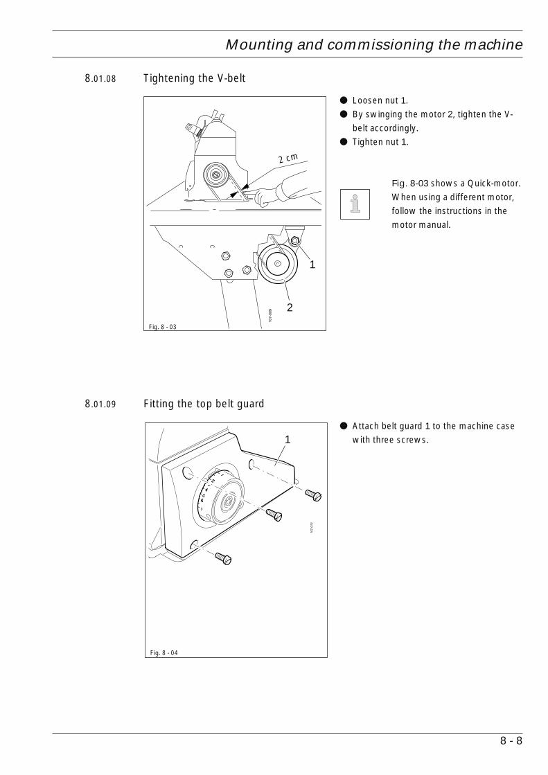
8.01.08 Tightening the V-belt
● Loosen nut 1.● By swinging the motor 2, tighten the V-
belt accordingly.● Tighten nut 1.
Fig. 8-03 shows a Quick-motor.When using a different motor,follow the instructions in themotor manual.
Fig. 8 - 03
8.01.09 Fitting the top belt guard
● Attach belt guard 1 to the machine casewith three screws.
Fig. 8 - 04
1
2
2 cm
1

Mounting and commissioning the machine
8 - 9
8.01.10 Fitting the bottom belt guard.
● The belt guard 1 must be located to allowfree movement of the motor pulley andthe drive belt.
● Tighten screws 2.
Fig. 8-05 shows a Quick-motor.When using a different motor,follow the instructions in themotor manual.
8.01.11 Chain for securing the pedal
● Secure chain 1 for raising the sewing footto lever 2 and to the right pedal.
Fig. 8 - 06
1
2
1
Fig. 8 - 05
22

Mounting and commissioning the machine
8 - 10
8.01.12 Mounting the reel stand
● Mount the reel stand as shown in Fig. 8-07.● Afterwards insert the stand in the hole in the table top and attach it with the nuts
provided.
Fig. 8 - 07

Mounting and commissioning the machine
8 - 11
8.02 Commissioning
● Check the machine, especially the electric wires, for any damage.● Clean the machine thoroughly and then oil it, see Chapter 10 Care and Maintenance.● Have specialists check, whether the machine’s motor can be used with the existing
mains voltage, and whether it is connected properly in the terminal box. If there are anydiscrepancies, do not operate the machine.
● When the machine is running, the balance wheel should turn away from the operator.
8.03 Switching the machine on/off
● Switch the machine on, see Chapter
7.01 Main switch.
● Carry out a test run, making sure that oilcan be seen in inspection glass 1.
Fig. 8 - 08
1

Preparation
9 - 1
9 Preparation
All regulations and instructions in this Instruction Manual are to be observed!Special attention is to be paid to the safety regulations!
All preparation work is only to be carried out by appropriately trained personnel.Before all preparation work, the machine is to be separated from the electricitysupply by removing the plug from the mains or switching off the On/Offswitch!
9.01 Inserting the needle
Switch off the machine!Danger of injury due tounintentional starting of themachine!
Only use needles from thesystem intended for themachine, see Chapter 3
Specifications.
● By turning the balance wheel, bring theneedle bar to its t.d.c.
● Loosen screw 1.● Insert the needle as far as possible.● The long needle groove must be facing
forwards.● Tighten screw 1.
Fig. 9 - 01
1
9.02 Threading the needle thread
Switch off the machine!Danger of injury if the machine starts accidentally!
● Thread the needle thread as shown in the corresponding diagram (see next page).● Adjust the relevant needle thread tension by turning milled nuts 1.
1

Preparation
9 - 2
9.02.01 Threading diagram for the PFAFF 5704
Fig. 9 - 02
1 1
1
9.02.02 Threading diagram for the PFAFF 5714
Fig. 9 - 03
1 11
1

Preparation
9 - 3
9.02.03 Threading diagram for the PFAFF 5716
Fig. 9 - 04
9.02.04 Threading diagram for the PFAFF 5742
Fig. 9 - 05
1 1
1
1
1 1
1
1

Preparation
9 - 4
9.03 Adjusting the stitch length
Fig. 9 - 07
1
● Press down stop button 2 and set the required stitch length on balance wheel 1.
Fig. 9 - 06
2
9.04 Adjusting the fullness
● Loosen screw 1.● Adjust lever 2 according to the required
fullness.● Retighten screw 1.
Top setting = stretchBottom setting = gather
Fig. 9 - 08
1
-
+
-
+
2
S. 9-4
9.03
9.04
Preparation
9 - 5
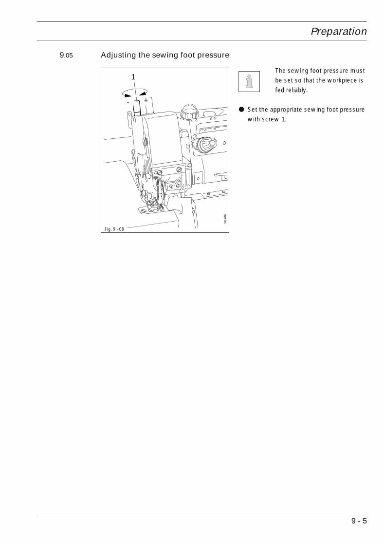
9.05 Adjusting the sewing foot pressure
The sewing foot pressure mustbe set so that the workpiece isfed reliably.
● Set the appropriate sewing foot pressurewith screw 1.
Fig. 9 - 08
1
- +

Care and maintenance
10 - 1
10 Care and maintenance
10.01 Maintenance intervals
Clean the machine ........................ once a day, more often when in continuous operation
Clean the hook compartment ........ once a day, more often when in continuous operation
Check the oil level ..................................................................................................... daily
Change the oil ............................... 4 weeks after commissioning, then every six months
Oil the thread lubrication .................................................................................. as required
Oil the machine ..................................... during commissioning and after long downtimes
Change the knife .............................................................................................. as required
These maintenance intervals are calculated for the average running time of asingle shift operation. If the machine is operated more than this, shorterintervals are recommended.
10.02 Cleaning the machine
The cleaning cycle required for the machine depends on following factors:
● Single or several shift operation● Amount of dust resulting from the workpiece
It is therefore only possible to stipulate the best possible cleaning instructions for each indivi-dual case.
For all cleaning work the machine must be disconnected from the mains byswitching off the on/off switch or by disconnecting the mains plug!Danger of injury if the machine starts accidentally!
To avoid breakdowns, the following cleaning work is recommended for single shift operation:● Clean hook compartment and needle area several times a day.● Clean the entire machine at least once a day.

Care and maintenance
10 - 2
10.04 Checking the oil level
● When the machine is at a standstill,check whether the oil level in inspectionglass 1 is between both markings.
● If necessary, remove plug 2 and pour inoil to the top marking.
● Replace plug 2.
Only use oil with a meanviscosity of 22.0 mm2/s at 40°Cand a density of 0.865 g/cm3 at15°C.
We recommendPFAFF sewing machine oil, partno. 280-1-120 144.
Fig. 10 - 02
10.03 Cleaning the hook compartment
Switch off the machine!Danger of injury if the machineis started accidentally!
● Open the hook compartment cover.● Clean the hook compartment.● Close the cover.
Fig. 10 - 01
1
2

Care and maintenance
10 - 3
4
3
10.05 Changing the oil
Fig. 10 - 03
Switch off the machine!Danger of injury if the machine starts accidentally!
The oil must not get into the sewer system! Danger of damage to theenvironment!
● Place a suitable vessel in position and remove screw 1.● Let the oil drain off completely.● Retighten screw 1 with a new sealing ring 2.● Remove inspection glass 3 and pour in fresh oil up to the top marking of inspection glass 4.● Screw inspection glass 3 back into place.● Carry out a test run and check whether the oil in inspection glass 3 is visible.
Only use oil with a mean viscosity of 22.0 mm2/s at 40°C and a density of0.865 g/cm3 at 15°C.
We recommendPFAFF sewing machine oil, part no. 280-1-120 144.
Fig. 10 - 04
12

Care and maintenance
10 - 4
10.06 Oiling the thread lubrication
Fig. 10 - 05
Switch off the machine!Danger of injury if the machine starts accidentally!
● There must always be oil in oil tank 1 and felt pad 2.● When required, fill oil into oil tank 1 or soak felt pad 2 with oil.
We recommend PFAFF thread lubricating oil, part no. 280-1-120 217.
Fig. 10 - 06
1
2

Care and maintenance
10 - 5
10.07 Oiling the machine
Fig. 10 - 07
Switch off the machine!Danger of injury if the machine starts accidentally!
● Before commissioning and before operation after long downtimes, a few extra drops ofoil should be applied to the needle bar and hook bar (see arrow).
Only use oil with a mean viscosity of 22.0 mm2/s at 40°C and a density of0.865 g/cm3 at 15°C.
We recommendPFAFF sewing machine oil, part no. 280-1-120 144.

Care and maintenance
10 - 6
10.08 Changing the knife
Fig. 10 - 08
Switch off the machine!Danger of injury if the machine starts accidentally!
Preparation
● Loosen screw 1, move knife holder 2 as far as possible to the left and slightly tightenscrew 1.
Changing the top knife
● Using the balance wheel, position knife holder 3 at t.d.c., unscrew screw 4 and removeknife 5.
● Insert a new knife and slightly tighten screw 4.
Changing the bottom knife
● Unscrew screw 6 and remove knife 7.● Insert new knife and slightly tighten screw 6.
Adjustment
The knives 5 and 7 should be positioned so that❍ the blade of the top knife 5 and of the bottom knife 6 overlap by 0.5 – 1.0 mm.❍ the bottom knife 7 is 0.0 -0.3 mm below the needle plate and❍ the knives 5 and 7 cross each other at their central points.
● Position knives 5 and 7 accordingly and tighten screws 4 and 6.● Adjust the cutting pressure with knife holder 2 and tighten screw 1.
1
4
6
5
2
7
0 - 0
.3 m
m
3
0.5
- 1,0
mm

Adjustment
11 - 1
11.03 Settings on the PFAFF 5704
11 Adjustment
Please observe all notes from Chapter 1 Safety of the instruction manual! In
particular care must be taken to see that all protective devices are refittedproperly after adjustment, see Chapter 1.06 Danger warnings of the
instruction manual!The machine must be disconnected from the electrical power supply.
11.01 Notes on adjustment
All adjustments may only be carried out by qualified personnel. Machine covers, which are
removed for control and adjustment work, must be replaced before the renewed operationof the machine.
11.02 Tools, gauges and other accessories
● 1 set of screwdrivers with blade widths from 2 to 10 mm● 1 set of spanners with jaw widths from 7 to 14 mm
● 1 set of Allen keys from 1.5 to 6 mm● 1 metal ruler, part no. 08-880 218-00
5704-01 10,1 4,2 5,1 0,9 - 1,1 5,5
5704-16S2 10,1 4,2 5,1 0,9 - 1,1 5,5
5704-17A 10,1 4,2 5,1 0,9 - 1,1 5,5
5704-180 10,1 4,2 5,1 0,9 - 1,1 3,5
Fabricclearance
[mm]
Subclass Needle barheight[mm]
Lower looperto needleclearance
[mm]
Upper looperto needleclearance
[mm]
Height ofbottom
feed dog[mm]

Adjustment
11 - 2
11.04 Settings on the PFAFF 5714
5714-... 10,4 4,2 5,8 0,9 - 1,1 5,5
11.05 Settings on the PFAFF 5716
5716-38A 10,6 3,9 5,1 0,9 - 1,1 5,5 1,5
5716-70A 10,6 3,9 5,1 0,9 - 1,1 5,5 1,5
5716-86A 12,0 3,6 5,1 0,9 - 1,1 5,5 1,5
11.06 Settings on the PFAFF 5742
5742-02-250 8,7 1,7 1,7 0,9 - 1,1 3,5
Fabricclearance
[mm]
Subclass Needle barheight[mm]
Lower looperto needleclearance
[mm]
Upper looperto needleclearance
[mm]
Height ofbottom
feed dog[mm]
Fabricclearance
[mm]
Subclass Needle barheight[mm]
Lower looperto needleclearance
[mm]
Upper looperto needleclearance
[mm]
Height ofbottom
feed dog[mm]
Fabricclearance
[mm]
Subclass Needle barheight[mm]
Chainstitchlooper to right
needleclearance
[mm]
Chainstitchlooper to left
needleclearance
[mm]
Height ofbottom
feed dog[mm]
Chainstitchlooper to
needleclearance
[mm]

Wearing parts
12 - 1
12 Wearing parts
This is a list of the most important wearing parts.A detailed parts list for the complete machine is included with the accessories.In case of loss the parts list can be downloaded from the internet addressWWW.pfaff-industrial.com/de/service/download/index.php3. As an alterna-tive to the internet download the parts lists can also be ordered in book formunder part no. 296-12-18 606.
J005292-HU
J001175-2
J005492
J005484HC
PFAFF 5716, 5742 PFAFF 5716, 5742
J004009HC
J001175-3 (PFAFF 5716, 5742)J001189 (PFAFF 5704, 5714)
J002902
J202527A (PFAFF 5742)J201121A (PFAFF 5704, 5714, 5716)
J005088
J202295 (PFAFF 5704, 5714)J204161 (PFAFF 5716)J208393 (PFAFF 5742)
J002193
System DCx27

Wearing parts
12 - 2
J204062 (PFAFF 5704-01, -16S2, -17, -180)J204949 (PFAFF 5714-13)J209733 (PFAFF 5714-181)J204702 (PFAFF 5716-38A, -70A)J204703 (PFAFF 5716-86A)
J001998-2
J204072 (PFAFF 5704, 5714, 5716)
J001175-3
J209685 (PFAFF 5716-38A, -70A, PFAFF 5742)J2096851-HC (PFAFF 5716-86A)
J209729 (PFAFF 5742)
J001189

© P
FAFF
Indu
strie
syst
eme
und
Mas
chin
en A
G 2
009,
PFA
FF is
the
exc
lusi
ve t
rade
mar
k of
VS
M G
roup
AB
.PFA
FF In
dust
riesy
stem
e un
d M
asch
inen
AG
is a
n au
thor
ized
lice
nsee
of
the
PFA
FF t
rade
mar
k.
PFAFF Industriesysteme und Maschinen AG
Hans-Geiger-Str. 12 - IG NordD-67661 Kaiserslautern
Telefon: +49 - 6301 3205 - 0
Telefax: +49 - 6301 3205 - 1386
E-mail: [email protected]
Gedruckt in der BRD / Printed in Germany / Imprimé en la R.F.A. / Impreso en la R.F.A