dds design document - initial release - stanford...
TRANSCRIPT
Solar Dynamics Observatory (SDO) Project
Data Distribution System (DDS)
Design Specification
464-GS-SPEC-0084
Effective Date: May, 2005
Expiration Date:
Prepared by: Thomas G. Bialas /Code 564
CHECK THE SDO MIS AT https://sdomis.gsfc.nasa.govTO VERIFY THAT THIS IS THE CORRECT VERSION PRIOR TO USE.
Goddard Space Flight CenterGreenbelt, Maryland
National Aeronautics andSpace Administration
INITIAL RELEASE
464-GS-SPEC-0084DRAFT
CM FOREWORD
This document is Solar Dynamics Observatory Project controlled document. Changes to this document require prior approval of the SDO Project CCB Chairperson. Proposed changes shall be submitted to the SDO Project Configuration Management Office (CMO), along with supportive material justifying the proposed change.
Questions or comments concerning this document should be addressed to:
SDO Configuration Management OfficeMail Stop 464Goddard Space Flight CenterGreenbelt, Maryland 20771
Release Date ii

464-GS-SPEC-0084DRAFT
Signature Page
Prepared by:
_______Thomas G. Bialas DateSDO Data Distribution System ManagerGoddard Space Flight Center Code 564
Reviewed by:
_______<Enter Name Here> Date<Enter Position Title Here><Enter Org/Code Here>
_________ <Enter Name Here> Date<Enter Position Title Here><Enter Org/Code Here>
_______<Enter Name Here> Date<Enter Position Title Here><Enter Org/Code Here>
_________ <Enter Name Here> Date<Enter Position Title Here><Enter Org/Code Here>
Concurred by:
_______Hun Tann DateGround System Implementation ManagerGSFC / 581.0
_________ Raymond J. Pages DateGround System ManagerGSFC / 581.0
Release Date iii

464-GS-SPEC-0084DRAFT
DOCUMENT CHANGE RECORD Sheet:1of 1REV/ VER
LEVELDESCRIPTION OF CHANGE
APPROVEDBY
DATEAPPROVE
DDraft 1 – GST review 10/2004
Draft 2 – Internal GS review 4/2005
Draft 3 – GST and Program Review 7/2005
Release Date iv

464-GS-SPEC-0084DRAFT
Table of Contents
1.0 INTRODUCTION........................................................................................................21.1 DOCUMENT PURPOSE AND SCOPE..................................................................21.2 DOCUMENT STRUCTURE....................................................................................21.3 REFERENCE DOCUMENTS.................................................................................2
2.0 DDS OVERVIEW.......................................................................................................52.1 GROUND SYSTEM DESCRIPTION......................................................................52.2 DDS DESIGN OVERVIEW.....................................................................................6
2.2.1 Architecture......................................................................................................82.2.1.2.1 Prototype Findings............................................................................262.2.1.2.2 Trade Study Findings........................................................................342.2.1.2.3 Design Choice Analysis Findings......................................................61
2.2.2 External Interfaces.........................................................................................892.2.3 Hardware.......................................................................................................912.2.4 Network Design..............................................................................................922.2.5 Data Management.........................................................................................92
3.0 DDS DESIGN DESCRIPTION.................................................................................963.1 FRONT END PROCESSOR DESIGN..................................................................96
3.1.1 Design Abstract..............................................................................................963.1.1.2.1 FEP High Data Rate Receiver..........................................................983.1.1.2.2 FEP VCDU Server..........................................................................1023.1.1.2.3 FEP 7TB RAID................................................................................102
3.1.2 External Interfaces.......................................................................................1053.1.3 Execution Control and Data Flow.................................................................1053.1.4 Reliability, Fault Tolerance and Failure Response.......................................1103.1.5 Automation...................................................................................................111
3.2 QUALITY COMPARE PROCESSOR DESIGN..................................................1123.2.1 Design Abstract............................................................................................1123.2.2 External Interfaces.......................................................................................1143.2.3 Execution Control and Data Flow.................................................................1153.2.4 Reliability and Fault Tolerance Considerations............................................1183.2.5 Automation...................................................................................................120
3.3 TEMPORARY ONLINE ARCHIVE DEVICE DESIGN (TOAD)...........................1203.3.1 Design Abstract............................................................................................1203.3.2 External Interfaces.......................................................................................1263.3.3 Execution Control and Data Flow.................................................................1263.3.4 Reliability and Fault Tolerance Considerations............................................1263.3.5 Automation...................................................................................................128
3.4 PERMANENT ONLINE ARCHIVE DEVICE DESIGN (POAD)...........................1293.4.1 Design Abstract............................................................................................1293.4.2 External Interfaces.......................................................................................1293.4.3 Execution Control and Data Flow.................................................................1293.4.4 Reliability and Fault Tolerance Considerations............................................1293.4.5 Automation...................................................................................................129
Release Date v

464-GS-SPEC-0084DRAFT
3.5 FILE OUTPUT PROCESSOR DESIGN (FO).....................................................1293.5.1 Design Abstract............................................................................................1293.5.2 External Interfaces.......................................................................................1323.5.3 Execution Control and Data Flow.................................................................1333.5.4 Reliability and Fault Tolerance Considerations............................................1363.5.5 Automation...................................................................................................137
3.6 DDS SDOGS INTEGRATED MANAGER (DSIM) DESIGN................................1383.6.1 Design Abstract............................................................................................1383.6.2 Execution Control and Data Flow.................................................................1413.6.3 Reliability and Fault Tolerance Considerations............................................1443.6.4 Automation...................................................................................................144
APPENDIX A ABBREVIATIONS AND ACRONYMS...................................................145
Release Date vi

464-GS-SPEC-0084DRAFT
List of FiguresFigure Page
Figure 2-1 SDO Ground System Overview.....................................................................................6Figure 2-2. Data Distribution System..............................................................................................7Figure 2-3 DDS Prototype Architecture and Design.....................................................................27Figure 2-4 As-Built DDS Prototype [Building 11 Lab Room E240]............................................32Figure 2-5 TSI Test Modulator, with external clock....................................................................35Figure 2-6 IN-SNEC CW Mode, 100 kHz Span...........................................................................36Figure 2-7 IN-SNEC CW Mode, 100 kHz Span...........................................................................37Figure 2-8 IN-SNEC CW Mode, 20 kHz Span............................................................................37Figure 2-9 Signal Generator, HP8780A, CW Mode, 20 kHz Span..............................................38Figure 2-10 IN-SNEC after a Test Modulator Board replacement, w/external clock..................38Figure 2-11 IN-SNEC after Test Modulator Board replacement, w/out external clock (5 db/div,
Span 10 kHz, RBW 100 Hz).........................................................................................................39Figure 2-12 Initial BER comparisons of vendor units, both with and without ½ rate
convolutional encoding.........................................................................................................41Figure 2-13 BER testing using the TSI Test Mod Source, both vendor units with and without
convolutional half rate encoding...........................................................................................42Figure 2-14 Comparison of BER performance before and after IN-SNEC card replacement....43Figure 2-15 Simplified NAS..........................................................................................................51Figure 2-16 Simplified SAN..........................................................................................................52Figure 2-17 Communication Protocol Test Bed............................................................................58Figure 2-18 RAID Backplane Capabilities Comparison..............................................................62Figure 2-19 DDS Contingency Framework...................................................................................70Figure 2-20 Baseline DDS – Pre-Failures.....................................................................................72Figure 2-21 FEP Failure and Failover...........................................................................................73Figure 2-22 QCP Failure and Failover..........................................................................................73Figure 2-23 SAN Failure and Failover..........................................................................................74Figure 2-24 FOP Failure and Failover..........................................................................................74Figure 2-25 DDS Hardware and LAN – Simplified View............................................................93Figure 2-26DDS Network Design – Simplified View...................................................................95Figure 3-1 DDS Complete Software CSCIs.................................................................................96Figure 3-2 DDS Front End Processor (FEP) CSCIs (excludes HDR)..........................................98Figure 3-3 Front End Processor (FEP) Architecture Overview....................................................98Figure 3-4 FEP High Data Rate Recorder Overview...................................................................99Figure 3-5 FEP VCDU Server....................................................................................................102Figure 3-6 FEP RAID Storage....................................................................................................104Figure 3-7 FEP RAID Storage Communications Configuration.................................................104Figure 3-8 DDS QCP CSCIs.....................................................................................................113Figure 3-9 QCP Server...............................................................................................................114Figure 3-10 DDS Core RAID Storage........................................................................................124Figure 3-11 FEP RAID Storage Communications Configuration..............................................125Figure 3-12 File Output SW CSCIs............................................................................................130Figure 3-13 FO Server................................................................................................................132Figure 3-14 DSIM SW CSCIs.....................................................................................................138Figure 3-15 DSIM Server............................................................................................................139
Release Date vii

464-GS-SPEC-0084DRAFT
Release Date viii
464-GS-SPEC-0084DRAFT
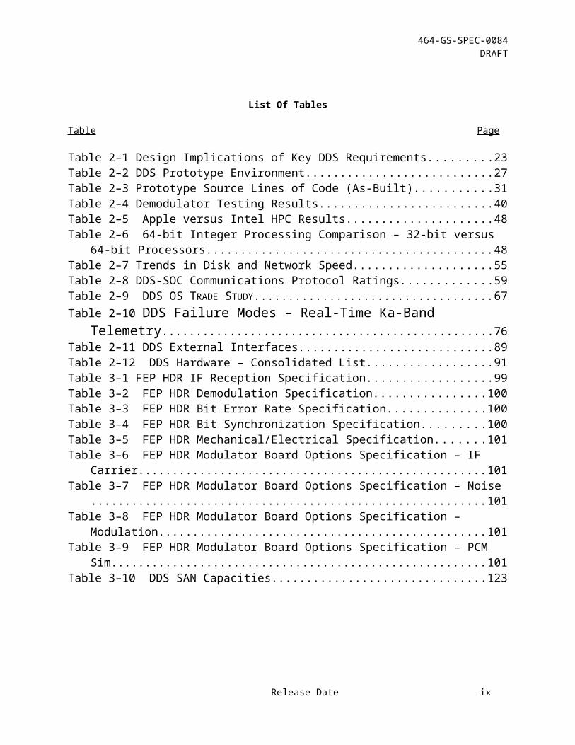
List Of Tables
Table Page
Table 2–1 Design Implications of Key DDS Requirements..........................................................23Table 2–2 DDS Prototype Environment........................................................................................27Table 2–3 Prototype Source Lines of Code (As-Built).................................................................31Table 2–4 Demodulator Testing Results.......................................................................................40Table 2–5 Apple versus Intel HPC Results..................................................................................48Table 2–6 64-bit Integer Processing Comparison – 32-bit versus 64-bit Processors...................48Table 2–7 Trends in Disk and Network Speed..............................................................................55Table 2–8 DDS-SOC Communications Protocol Ratings.............................................................59Table 2–9 DDS OS TRADE STUDY...............................................................................................67Table 2–10 DDS Failure Modes – Real-Time Ka-Band Telemetry................................76Table 2–11 DDS External Interfaces.............................................................................................89Table 2–12 DDS Hardware – Consolidated List..........................................................................91Table 3–1 FEP HDR IF Reception Specification..........................................................................99Table 3–2 FEP HDR Demodulation Specification.....................................................................100Table 3–3 FEP HDR Bit Error Rate Specification.....................................................................100Table 3–4 FEP HDR Bit Synchronization Specification............................................................100Table 3–5 FEP HDR Mechanical/Electrical Specification.........................................................101Table 3–6 FEP HDR Modulator Board Options Specification – IF Carrier...............................101Table 3–7 FEP HDR Modulator Board Options Specification – Noise.....................................101Table 3–8 FEP HDR Modulator Board Options Specification – Modulation............................101Table 3–9 FEP HDR Modulator Board Options Specification – PCM Sim...............................101Table 3–10 DDS SAN Capacities...............................................................................................123
Release Date ix
464-GS-SPEC-0084DRAFT
List of TBDs/TBRs
Item No.
Location Summary Ind./Org. Due Date
Release Date x

1.0 INTRODUCTION
1.1 DOCUMENT PURPOSE AND SCOPE
This is the Design Specification for the Solar Dynamics Observatory (SDO) Data Distribution System (DDS). The purpose of this document is to fully specify the hardware and software components of the DDS and how they will support SDO through each of the mission phases. A high-level description of the SDO Ground System is given and the interfaces between the DDS and each ground system element are described. The full definition of each interface is given in the appropriate Interface Control Document.
1.2 DOCUMENT STRUCTURE
Section 1.0 describes the purpose, scope, and organization of the document and provides a list of reference documents.
Section 2.0 identifies the DDS external interfaces and the DDS components.
Section 3.0 presents the design at the top-level computer software component (TLCSC) level. For each TLCSC, a design abstract, execution control, data flow, reliability, fault tolerance considerations, and automation are iincluded.
Section 4.0 presents the detailed design for all components and subcomponents that are new or modified for this mission.
Section 5.0 defines the format of the DDS internal and external data elements. Data definitions will not be duplicated for data elements that are already specified in existing documentation.
Appendices include a list of abbreviations and acronyms, a description of DDS automation tools, and any other information that is needed.
1.3 REFERENCE DOCUMENTS
Document Number Document Name464-SYS-REQ-0004 SDO Mission Requirements
Document (MRD)464-GS-PLAN-0010 SDO Project Operations Concept
Document464-GS-REQ-0005 Detailed Mission Requirements
(DMR) for SDO Ground System

Document Number Document Name
464-GS-REQ-0046 SDO Mission Operations Center (MOC) Requirements Specification
464-GS-REQ-0049 SDO Data Distribution System (DDS) Requirements Specification
464-GS-REQ-0050 SDO Ground Station (SDOGS) Requirements Specification
464-FDS-SPEC-0039, SDO Flight Dynamics Requirements Specifications (FDS SRS)
464-GS-ICD-0010 SDO Interface Control Document (ICD) between the Data Distribution System (DDS) and the Science Operations Centers (SOCs)
464-CDH-ICD-0012 High Speed Bus (HSB) Interface Control Document (ICD)
464-GS-ICD-0064 Interface Control Document (ICD) between the SDO Ground Station (SDOGS) and the Mission Operation Center (MOC)1
464-GS-ICD-0066 DSIM to GS ICD464-GS-ICD-0065 SDO Interface Control Document
(ICD) between the Mission Operation Center (MOC) and the External Network
464-GS-ICD-0001 SDO Interface Control Document (ICD) between the Mission Operation Center (MOC) and the Science Operations Centers (SOCs)2
464-GS-LEGL-0030 White Sands Memorandum of Understanding (MOU)
464-SYS-SPEC-0033 SDO CCSDS Implementation Document
1 This document has been included to determine derived performance requirements. DSIM provides command translation and status translation and transmission for SDOGS.2 This document has been included to determine derived performance requirements. MOC service performance requirements are, in part, derived from MOC service requirements.

Document Number Document Name464-SCI-REVW-0013 Data Archiving in the Era of SDO:
Did I Say Terabyte? I Meant Petabyte
NPR 2810 NASA Security Processes and Requirements
NHB 2410.9 NASA Automated Information Security Handbook
530-WSC-0009 WSC Security Plan530-WSC-0024 WSC Information Technology
Security Handbook (ITSSP)464-GS-HDBK-0002 SDO Ground System Product
Development Handbook464-GS-PLAN-0056 SDO Network and
Communications Contingency and Disaster Recovery Plan
464-GS-PLAN-0060 SDO IT Risk Assessment Plan464-GS-PLAN-0082 SDO Ground System Contingency
and Disaster Recovery Plan

2.0 DDS OVERVIEW
2.1 GROUND SYSTEM DESCRIPTION
The SDO Ground System (GS) has two main functions: (1) to receive and distribute the science telemetry to the science users, and (2) to monitor the health and safety of the observatory and control its operations.
The SDO GS is composed of the following main elements:
The SDO Ground Station (SDOGS), which consist of two SDO-dedicated antennas and all the associated equipment and software, located in White Sands, NM. The ground stations provide the ground to spacecraft link on a continuous basis for telemetry downlink in both KA-band and S-band, and for command uplink in S-band. An external tracking station will be used to support special operations such as launch and early orbit, and to supplement the SDO dedicated ground stations in specific functions, such as providing additional tracking data.
The Data Distribution System (DDS), also located in White Sands, NM, which receives the science telemetry data, processes it into files and distributes them to the instrument teams. DDS also provides a short-term storage capability and supports data retransmissions as needed.
The Mission Operations Center (MOC), located at the Goddard Space Flight Center (GSFC) in Greenbelt, MD. The MOC supports the traditional Telemetry and Command (T&C) functions, which allow the Flight Operations Team (FOT) to monitor the health and safety of the observatory and to control its operation. The MOC also provides mission planning functions, trending and analysis functions, automation utilities, remote control of the SDO Ground Stations and DDS, and Flight Dynamics attitude control and maneuver planning functions.
The Flight Dynamics Facility (FDF) performs orbit determination, tracking data verification and acquisition and tracking support for supporting ground stations.
The Science Operations Centers (SOCs), located at the Principal Investigators (PI) institutions:
The Helioseismic and Magnetic Imager (HMI) SOC and the Atmospheric Imaging Assembly (AIA) SOC are located in California. The Lockheed Martin Solar and Astrophysics Laboratory (LMSAL) in Palo Alto has the main responsibilities for instrument monitoring and control while Stanford University will support the science data reception.
The Extreme Ultraviolet Variability Experiment (EVE) SOC is located at the Laboratory for Atmospheric and Space Physics (LASP) in Boulder, CO.
The Communications Network, which provides the data and voice connections between all the GS elements.
Figure 2-1 provides an overview of the SDO Ground System.
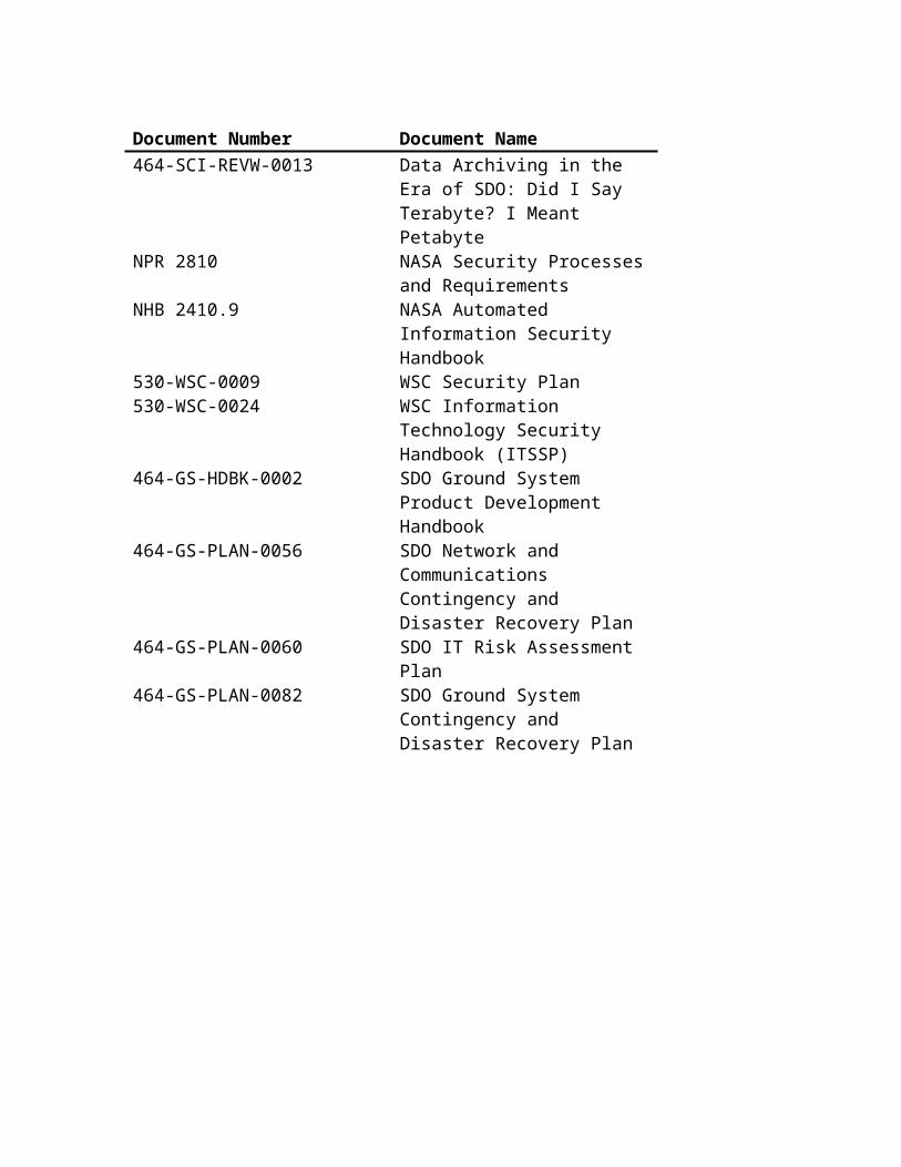
Figure 2-1 SDO Ground System Overview
2.2 DDS DESIGN OVERVIEW
The DDS is comprised of two main elements:
The high-rate Front End Processor (FEP) receives the down-converted IF signal from the Ka-Band segment, performs Viterbi and Reed-Solomon corrections and sorts the data by virtual channel. The FEPs are co-located with the antennas. There are redundant FEPs for each of the two antennas.
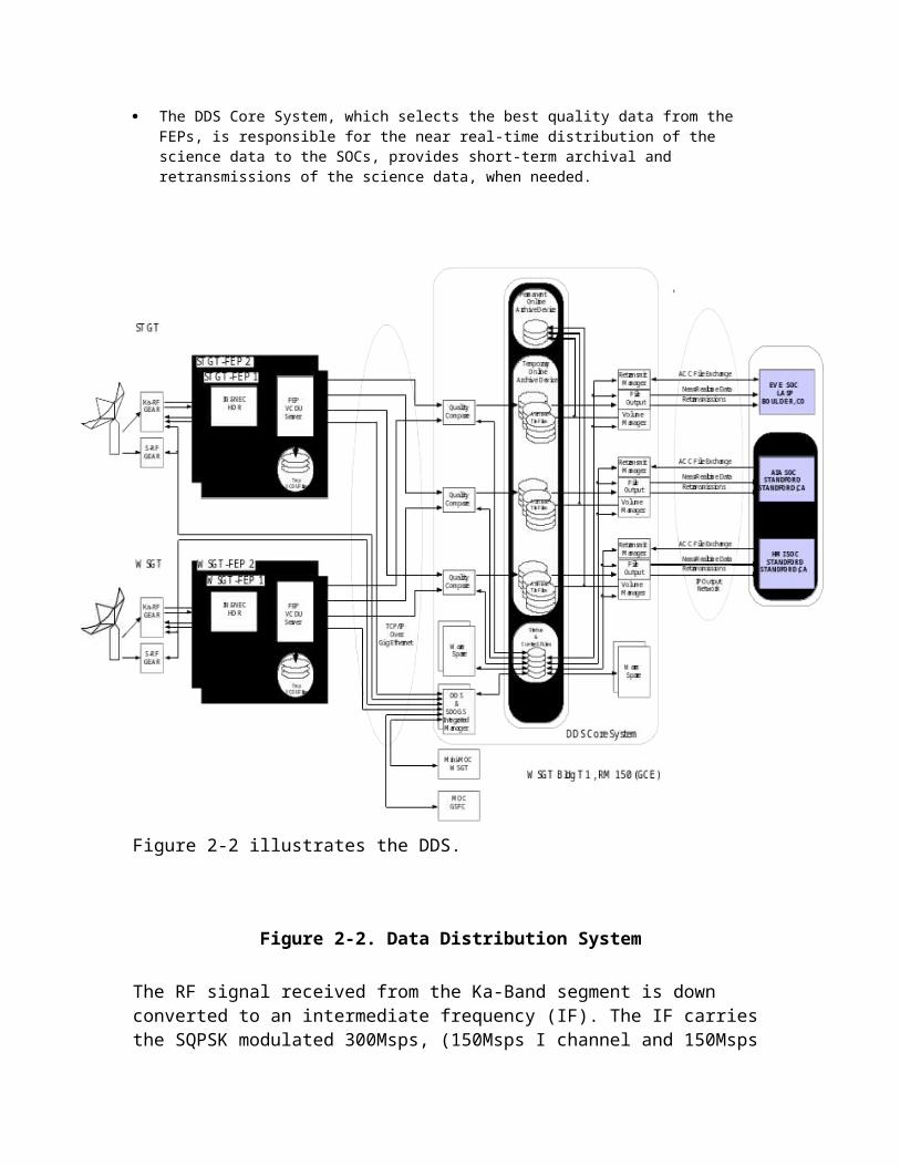
The DDS Core System, which selects the best quality data from the FEPs, is responsible for the near real-time distribution of the science data to the SOCs, provides short-term archival and retransmissions of the science data, when needed.
Telemetry & Command System
ASIST / FEDSTelemetry Monitoring
Command Management
HK Data ArchivalHK Level-0 Processing
Ground Station ControlDDS Control
Automated OperationsAnomaly detection
Flight DynamicsSystem
Maneuver Planning
Product Generation
R/T Attitude Determination
Sensor/Actuator Calibration
SDO Mission Operations Center
EVE SOC
Acquisition Data
Observatory Commands
Observatory HK Telemetry
Tracking Data
Integrated Trending& Plotting System
Mission Planning& Scheduling
Plan daily/periodic eventsCreate engineering plan
Generate Daily Loads
HMI Science Data (55Mbps)
Ka-Band:150 Mbps
Science Data
Instrument Commands/Loads
Data DistributionSystem
(Incl. 30-Day Science Data Storage)
Ka Science Data
AIA R/T HK Telemetry/ Science Planning and FDS Products
EVE R/T HK Telemetry Science Planning and FDS Products
Universal Space Network
S-Band HK Tlm
CMD, Acquisition
Data
Station/DDS Control
Station/DDS Status
SDO Ground StationWSGT
Ka-Band:150 Mbps
Science Data
S-Band: TRK, Cmd & HK Tlm
S-Band: TRK,Cmd & HK Tlm
Alert NotificationSystem
Flight Software Maintenance Lab
Flight software loadsSimulated housekeeping telemetry
S/C Memory dumpsSimulated commands
Same Interfaces
as WSGT Ground Station
HMI AIA JSOC
Stanford Univ.
Science Data Capture
LMSAL
Instrument Monitoring& Control
Instrument Commands/Loads
SDO Ground StationSTGT Flight Dynamics
Facility
Orbit DeterminationProduct Generation
Tracking Data
OD Products
Space Network(L&EO only)
S-Band: TRK,Cmd & HK Tlm
S-Band HK Tlm
Tracking Data
CMD
Acquisition DataS-Band: TRK, Cmd & HK Tlm
DDS & Ground Station Control
AIA Science Data (67Mbps) EVE Science Data (7Mbps)
(Palo Alto, CA)
(Stanford, CA)
Tracking Data
Ka Science Data
Status and
Control
LASP(Boulder, CO)
Science Data CaptureInstrument Monitoring
& Control
Data Ack. & Retrans. RequestsData Ack. & Retrans. Requests
FLATSAT
Instrument Commands/LoadsHMI R/T HK Telemetry/ Science Planning and FDS Products
SDO
WSC
FSW SupportTool Suite
DDS & SDOGSIntegrated Manager
GSFC
S-Band RF &FEP system
Ka-Band RF system
(Includes 72-hr storage)
DDS FEP(Incl. 120-hr
storage)
S-Band RF &FEP system
Ka-Band RF system
(Includes 72-hr storage)
DDS FEP(Incl. 120-hr
storage)
Status and
Control
Mini MOC

Figure 2-2 illustrates the DDS.
Figure 2-2. Data Distribution System
The RF signal received from the Ka-Band segment is down converted to an intermediate frequency (IF). The IF carries the SQPSK modulated 300Msps, (150Msps I channel and 150Msps Q channel) downlink signal which is input into the Ka-Band receiver (which is part of the FEP). The high-rate Front End Processors (FEP) are physically co-located with each SDO antennas. Two FEPs for each antenna provide full redundancy. The FEPs perform demodulation, Viterbi decoding, I & Q channel recombining, frame synchronization, pseudo-random noise decoding and Reed-Solomon decoding; then stores the composite VCDU stream in a 5-day temporary circular buffer for reprocessing

and failure recovery when necessary. The data is sent in near-real time to the DDS Core System.
The DDS Core System accepts data from either or both FEPs simultaneously. The data is compared for each VCID, and the best quality data is stored in TLM files. The files contain a fixed number of VCDUs approximately equal to 1-minute of data Thus, they are distributed to the SOCs with a latency of roughly 1 minute. The files are also archived in a short-term 30-day archive providing the capability to retransmit data as necessary. The DDS archive system is a fault tolerant RAID disk system, with a capacity of about 42 terabytes.
The operational scenario for science data distribution is based on the concept of providing files covering a fixed length of time and monitoring the transmissions by exchanging files with their associated status. The format and timing of this exchange is documented in the DDS-SOC ICD:
The Science data is sorted in files containing approximately one minute's worth of VCDUs for a single VC ID. Quality information for each data file is contained in a Quality and Accounting (QAC) file. The data and QAC files are automatically transferred to the SOCs with minimal delay, using SCP/TCP. DDS will attempt to deliver the data only one time. If the transmission fails, retransmissions can be requested by the SOCs. On-board errored frames are stored in the ERR files associated with each TLM file.
DDS maintains a catalog of all files available and their transmission status. At regular time intervals, on the order of once per hour, DDS will send a Delivery Status File (DSF) to the SOCs, listing all the files that exist within DDS and have not yet been acknowledged by the SOCs.
The SOCs answer with an Acknowledgement Status File (ASF), similar in format to the DSF file but, which either acknowledges a file receipt or requests its re-transmission.
DDS will queue all the retransmission requests and perform them as bandwidth allows. At the end of each day the SOC will create an acknowledgement file (ARC) containing the
confirmation of all files that it successfully received and archived on that day. The DDS will notify the SOC via email of any files that have not been acknowledged and are
older than a certain number of days (after 10 days and after 25 days). DDS will delete all files older than 30 days.
2.2.1 Architecture
2.2.1.1 Operations Considerations
The operations concept for the SDO mission drives key design choices within the DDS. The DDS design reflects complex choices analyzed and selected to best meet the needs of the SDO mission for its prime mission life, to meet the requirements of the SDO as flowed down to or derived for the DDS element and to perform within project budget allocations. Key DDS design drivers from the requirements are:

Requirement Affect Design ResponseSDO Mission Requirements Document 1.2.1 – “ The end-to-end HMI Data Capture budget requires 22 72-day periods, with each 72-day period capturing 95% of all possible science observations in order to be complete, including delivery of these data to the SOCs. The EVE and AIA data capture budgets require 90% of all possible science data over the 5 year mission life period. ‘All possible science’ is defined as all science observations that could be collected over the mission life assuming no viewing interruptions or data losses.”
RMAAuto-
recovery
DDS End-to-Endo The DDS must provide the line
outage and replay capability required to protect the SDO missions from an outage preceding the science data processing and best-quality data selection and product data storage activities.
o The DDS must provide first level automated response to anomalies, contingencies and failures. First level response is defined as an automated and automatic initial response to a discovered fault condition.
FEPo The FEP VCDU server must
provide the capability of replaying partially processed stored science data at communications rates equivalent to real time science data communications rates between the FEP system and the DDS Core.
o The FEP VCDU server and associated storage must have commercial data center level Reliability-Maintainability-Availability (RMA) specifications.
DDS Coreo The DDS Core servers and
associated storage must have commercial data center level RMA specifications.
o The DDS Core Quality Compare Processor (QCP) system must provide a minimum of 2.5X processing capability to support real time and replay science data stream processing (2.5X processing provides head room for any associated overhead relates to the loading).
o The DDS Core File Output Processor (FO) system must provide a minimum of 2.25X processing capability to ensure that the addition of potentially missing VCDUs from up to a 5-day outage does not raise DDS throughput VCDU processing end-to-end from the required 3 minutes or less.
o The DDS Core File Output Processor system must provide a minimum of 2.25X processing capability to ensure retransmissions of best-quality science data and associated quality information files do not affect ongoing real time science data file transmissions and that end-to-end throughput remains at 3 minutes or less per VCDU processed.

SDO Mission Requirements Document 1.2.2 – “ For the purpose of 1.2.1 an HMI observation shall be considered complete if it is at least 99.99% complete. The combined Instrument, Spacecraft, and Ground System shall provide an end-to-end data completeness of 99.6% over periods of minutes to hours for EVE and 99.9% for AIA”
RMAData AssuranceAuto-Recovery
Automation3
These instrument-based requirements determine reliability and availability requirements within the DDS to a great extent. However, further analysis established that these requirements also drive data integrity and recoverability requirements both end-to-end (replay-based) and within a FO subsystem which provides for request-initiated retransmissions from the DDS temporary archive. In addition to those DDS design responses outlined For SDO MRD 1.2.1 (above), this requirement mandates the following responses:
FEP o Accurate file management must
ensure availability of usable semi-raw data from the FEP system storage
o Comprehensive media management must ensure that the data as received is stored and retrievable by the FEP storage subsystem.
o The FEP system must provide media-level integrity including auto-recovery from media failures.
DDS Core o The DDS Core File Output at 20
3 Automation concerns specific design elements that provide automation of and/or control of a DDS activity through computer-based means. Status and monitoring activities are included within this grouping. Automatic behaviors are those activities that are activated, terminated or executed without operator intervention.

days and 28 days AND if any science productions have not been acknowledged by the SOCs, DDS Core File Output must send an email notification listing the files of interest.
o The DDS Core TOAD must provide sufficient throughput to simultaneously support real time science data processing and/or delivery, science data reprocessing and redelivery of up to 3 simultaneous replays and execution of retransmission requests.
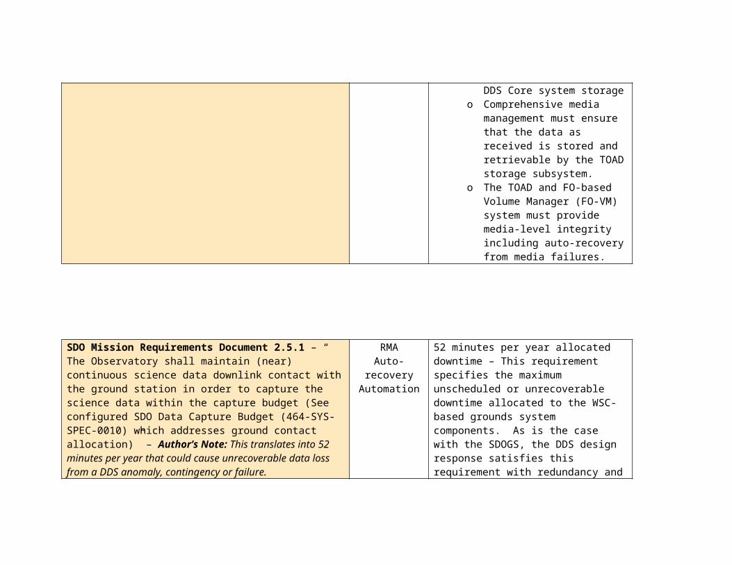
o File management processes must ensure availability of usable and accurate best-quality data from the DDS Core system storage
o Comprehensive media management must ensure that the data as received is stored and retrievable by the TOAD storage subsystem.
o The TOAD and FO-based Volume Manager (FO-VM) system must provide media-level integrity including auto-recovery from media failures.

SDO Mission Requirements Document 2.5.1 – “ The Observatory shall maintain (near) continuous science data downlink contact with the ground station in order to capture the science data within the capture budget (See configured SDO Data Capture Budget (464-SYS-SPEC-0010) which addresses ground contact allocation)” – Author’s Note: This translates into 52 minutes per year that could cause unrecoverable data loss from a DDS anomaly, contingency or failure.
RMAAuto-recovery
Automation
52 minutes per year allocated downtime – This requirement specifies the maximum unscheduled or unrecoverable downtime allocated to the WSC-based grounds system components. As is the case with the SDOGS, the DDS design response satisfies this requirement with redundancy and escalating recovery modes.
DDS End-to-Endo The DDS must provide sufficient
redundancy to ensure minimal disruption to operations and the science data processing.
o Vertical redundancy will be accomplished by providing a combination of warm and hot spares within each DDS function (FEP, QCP, FO, TOAD/POAD). Horizontal redundancy is accomplished via retransmissions (for processed science data products) or replays (for semi-raw data). In either case, the end-to-end response – from detection to resolution – cannot exceed an average of 1.25 minutes for those anomalies, contingencies or failures that can be handled via automated recovery.

SDO Mission Requirements Document 5.2.6.5 – “ The ground station shall employ and demonstrate a data distribution implementation with sufficient reliability to achieve error-free data distribution including science data retransmissions”
RMAAutomation
Auto-recovery
The requirement for error-free data distribution drives 5 key design choices
o The choice to store semi-raw and processed data on high-speed, high-integrity storage
o The separation of processing functionally within the DDS Core. Vertical allocation provides unary processing, thus reducing algorithm complexity within a function while improving visibility into the processing for recovery, restoration and troubleshooting.
o The decision to automate replay and retransmission and the further decision to create an application level protocol for retransmission requests and execution.
o The design of vertical and horizontal statusing and recovery. Built within each unary function is the ability to recover/failover. Moreover, through the status and monitoring capabilities, the DDS can respond to occurrences that impede or impact the processing of the science data stream – much like a production line is designed to ensure that raw materials flow through to become finished products. Varied auto-recovery capabilities exist at each functional hand-over point to provide the

quickest possible response to anomalies and failures.
o The TOAD/POAD management SAN provides more robust data integrity and more aggressive data recovery than a RAID system alone.
FEP o The FEP must provide a high-
reliability high-speed storage providing sufficient coverage to span the maximum MOC unstaffed period plus a 10% time margin.
o The FEP design places the FEP outside of the DDS.
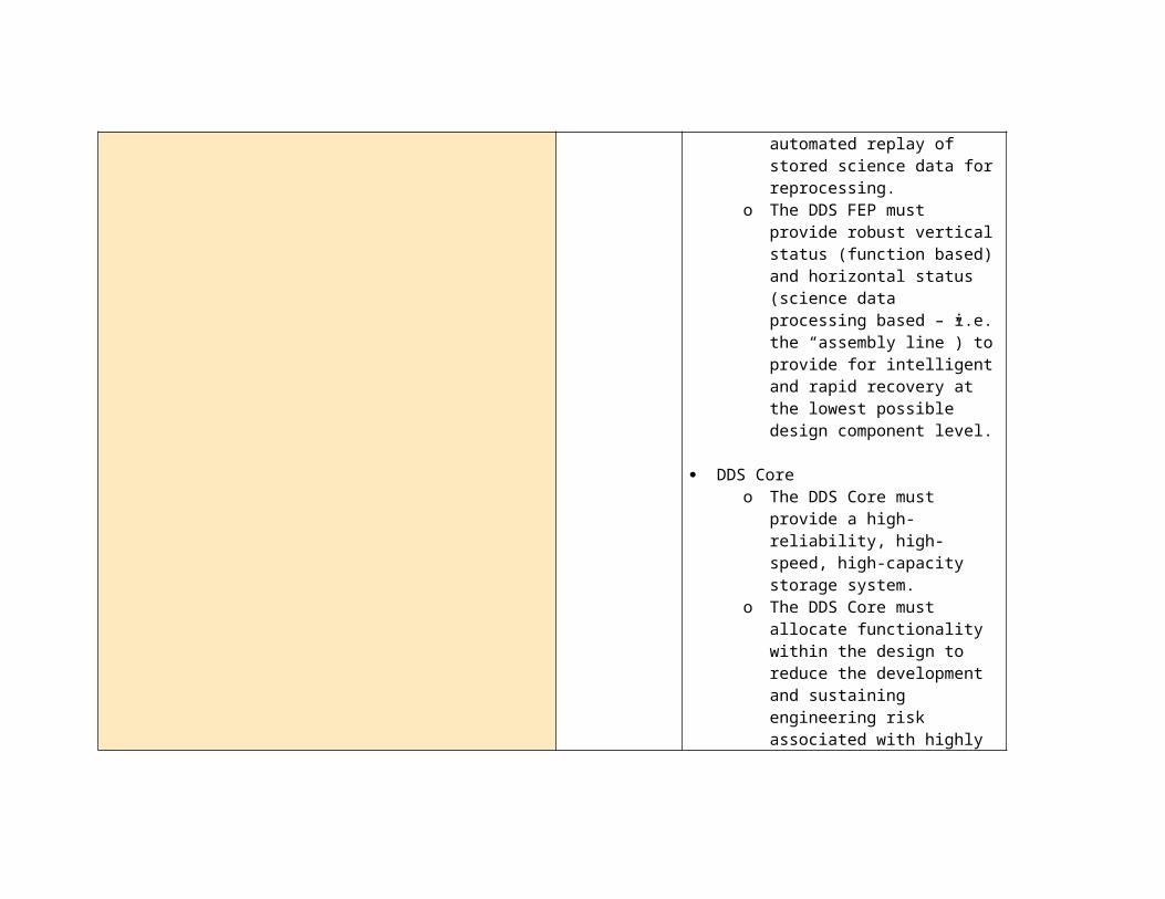
o The FEP must provide automated replay of stored science data for reprocessing.
o The DDS FEP must provide robust vertical status (function based) and horizontal status (science data processing based – i.e. the “assembly line”) to provide for intelligent and rapid recovery at the lowest possible design component level.
DDS Coreo The DDS Core must provide a
high-reliability, high-speed, high-

capacity storage system.o The DDS Core must allocate
functionality within the design to reduce the development and sustaining engineering risk associated with highly integrated software functionality.
o The DDS Core must provide automated and automatic 4retransmission capability via application-to-application interaction.
o The DDS core must provide robust vertical status (function based) and horizontal status (science data processing based – i.e. the “assembly line”) to provide for intelligent and rapid recovery at the lowest possible design component.
o The DDS core will implement a SAN in addition to a RAID
4 Automated – Users pushes the button to start process and process continues to completion. Automatic – DDS system/function initiates process without user interaction or intervention using operations response analysis results

SDO Mission Requirements Document 5.2.6.7 – “The ground station shall provide 30 days of temporary data storage to allow science data retransmission if required”
RMAAuto-recovery
Throughput
DDS Core o The DDS core must provide robust
vertical status (function based) and horizontal status (science data processing based – i.e. the “assembly line”) to provide for intelligent and rapid recovery at the lowest possible design component.
o The DDS Core must provide automated and automatic retransmission capability via application-to-application interaction.
o The DDS Core TOAD must provide sufficient throughput to simultaneously support real time science data processing and/or delivery, science data reprocessing and redelivery of up to 3 simultaneous replays and execution of retransmission requests.

DMR Requirement 2001
Ka-bandDownlink26.5 GHz (Dedicated SDO ground network only)
Real-Time Science Telemetry
SQPSK; Reed-Solomon Interleave depth=8;Viterbi R=1/2,K=7
150 Mbps&300 Msymbols/ sec
Nominal (geo-sync)
EVE=7Mbps, VC=3,6,19,22,35,38
HMI=55Mbps, VC=2,5,18,21,34,37
AIA=67Mbps, VC=1,4,17,20,33,36
RMAStorage
ThroughputAuto-Recovery
DDS End-to-Endo The DDS must provide high-
performance and high-throughput end-to-end through the use of multiprocessor systems, high bandwidth bus architectures, high-speed communications interfaces (internal and provided by IPNOC) and high availability through robust contingency/anomaly handling
o The DDS must provide sufficient redundancy to ensure minimal disruption to operations and the science data processing.
o Vertical redundancy will be accomplished by providing a combination of warm and hot spares within each DDS function (FEP, QCP, FO, TOAD/POAD). Horizontal redundancy is accomplished via retransmissions (for processed science data products) or replays (for semi-raw data). In either case, the end-to-end response – from detection to resolution – cannot exceed an average of 1.25 minutes for those anomalies, contingencies or failures that can be handled via automated recovery.
o The DDS must provide a blend of automatic and automated recovery
to maintain high availability. DDS Core
o The DDS core must provide robust vertical status (function based) and horizontal status (science data processing based – i.e. the “assembly line”) to provide for intelligent and rapid recovery at the lowest possible design component.
o The DDS Core must provide automated and automatic retransmission capability via application-to-application interaction.
o The DDS Core TOAD must provide sufficient throughput to simultaneously support real time science data processing and/or delivery, science data reprocessing and redelivery of up to 3 simultaneous replays and execution of retransmission requests.

DMR Requirement 2002 – “Ground networks supporting the SDO mission shall capture the health and safety and science data volumes provided below. SDO will downlink science and health and safety telemetry 24 hours a day, 7 days a week for five years. The SDO spacecraft will not include a data recorder for science. The maximum data volumes received at one ground site during normal operations is approximately:
Observatory health and safety data (S-band) = 350 Megabytes (MB) per day
Science data (Ka-band) = 1.4 Terabytes (TB) per day”
Storage DDS Coreo The DDS Core must provide a
high-reliability, high-speed, high-capacity storage system.
o The DDS core will implement a SAN in addition to a RAID
o The DDS Core TOAD must provide sufficient throughput to simultaneously support real time science data processing and/or delivery, science data reprocessing and redelivery of up to 3 simultaneous replays and execution of retransmission requests.
DMR Requirement 3300.3.2
DDS AIA SOC Science Data 101 Mbps Premium L-18 to EOMDDS EVE SOC Science Data 11 Mbps Premium L-18 to EOMDDS HMI SOC Science Data 83 Mbps Premium L-18 to EOM
ThroughputComm.
DDS End-to-Endo The DDS communications
network must work near peak rates while avoiding saturation above 80% for more than burst (350 seconds) per operational day
o The DDS must monitor the IPNOC provided services for degradation and report these to the MOC ASAP.
DDS Coreo The DDS must maintain file
processing throughput end-to-end at or under 3 minutes. The design provides multi-processor system with 1000BaseT and Fibre Channel interfaces to meet this

requirement.DMR Requirement 6100
Science Processing Item SDO Science TeamsDDS-to-SOC Data Latency Less than 3 minutesData Completeness 99.99% of data received by the DDSData Formats VCDUsMetadata Formats Text file following the associated data
file that contains data file size and timeData Delivery Mechanism File transfer; Fixed-size files spanning
approximately one minute’s worth of dataError Handling Discard VCDUs failing R-S decodingArchive Size 30 days
ThroughputData IntegrityComm. AlgorithmsStorage
DDS Coreo The DDS must have sufficient
processing and interface performance to maintain file processing throughput end-to-end at or under 3 minutes. The design provides multi-processor system with 1000BaseT and Fibre Channel interfaces to meet this requirement.
o The DDS core must provide robust vertical status (function based) and horizontal status (science data processing based – i.e. the “assembly line”) to provide for intelligent and rapid recovery at the lowest possible design component.
o The DDS quality and accounting algorithm must provide adequate indications that data completeness requirements have been met relative to the data received and processed.
o The DDS Core TOAD must provide sufficient throughput to simultaneously support real time science data processing and/or delivery, science data reprocessing and redelivery of up to 3 simultaneous replays and execution of retransmission

requests.o The DDS Core TOAD must
provide sufficient capacity to simultaneously store real time science data processing and/or delivery, science data reprocessing and redelivery of up to 3 simultaneous replays and execution of retransmission requests.
DMR Requirement 6100.1 – “The DDS data ingest function shall have a system availability of 99.99%”
RMAAuto-recovery
FEP o The FEP must provide a high-
reliability high-speed storage providing sufficient coverage to span the maximum MOC unstaffed period plus a 10% time margin.
o The FEP design places the FEP outside of the DDS.
o The FEP must provide automated replay of stored science data for reprocessing.
o The DDS FEP must provide robust vertical status (function based) and horizontal status (science data processing based – i.e. the “assembly line”) to provide for intelligent and rapid recovery at the lowest possible design component level.
DDS Core o The DDS core must provide robust
vertical status (function based) and

horizontal status (science data processing based – i.e. the “assembly line”) to provide for intelligent and rapid recovery at the lowest possible design component.
o The DDS Core must provide automated and automatic retransmission capability via application-to-application interaction.
o The DDS Core TOAD must provide sufficient throughput to simultaneously support real time science data processing and/or delivery, science data reprocessing and redelivery of up to 3 simultaneous replays and execution of retransmission requests.
Table 2–1 Design Implications of Key DDS Requirements
2.2.1.2 Trade Studies and Design Choice Analyses
The DDS design performed three forms of design choice validation:
o Prototyping – The critical path functions within the DDS were prototyped using the Rapid Application Prototyping (RAP) methodology.
Front End Processing – The High Data Rate Receiver and the associated FEP VCDU server and FEP storage including FEP RAID storage quota management
Quality Compare Processing – The servers receiving the discrete, decoded instrument science data streams and:
Selecting the best quality VCDU Generating the associated Quality and Accounting (QAC) file Storing the best quality VCDU to the TOAD and the QAC to
the POAD File Output Processor – The servers retrieving the best quality files
from the TOAD and shipping the files to the SOCs and managing the TOAD storage at the functional level based on the age of the files
Retrieve the Best Quality VCDU and QAC file(s) Ship the VCDU and QAC files Delete files over 30 days old
DDS-SDOGS Integrated Manager – Although not part of the original approved prototype plan, the DSIM server has been prototyped. The DSIM provides status collection and submission to the MOC as well as accepting directives from the MOC that control the DDS and SDOGS systems, subsystems and equipment.
Receive periodic status from the SDOGS and DDS Summarize and reformat status and ship the composite status to
the MOC Receive directives from the MOC Translate the directive into the native form required by the
target system and forward to that systemo Trade Studies – To determine best choices for specific systems or equipment,
DDS conducted trade studies for: High Data Rate Receivers – TSI versus IN-SNEC DDS Server Farm – Dell versus Apple Storage Area Networks (SAN) versus Network Attached Storage
(NAS) CFDP versus MDP versus FTP versus sFTP/SCP versus FASTCopy
o Design Choice Analyses – While trade studies were not conducted for some choices, design analyses were done to clarify the choices or to confirm experience or assumptions made by the DDS engineering team.
RAID Backplane Vendor Choice RAID Levels – RAID0 versus RAID1 versus RAID5 versus RAID10 Windows versus Unix (and variants)

2.2.1.2.1 Prototype Findings
The decision to prototype key DDS function had its roots in the project-level systems engineering approach to “retire risks” as early in the project as possible. Towards that end, five key DDS “questions” were posed and answered by prototyping:
1. Can the DDS candidate architecture nominally support the processing throughput necessary at the 150Mbps data rate? A recurring concern focused on the impact of the SDO transmission data rate on the ground system. With no Ka-band 150Mbps on-orbit NASA mission to benchmark, prototyping would allow the project systems engineers to verify the feasibility of the architecture and to determine design choices necessary to achieve requirements satisfaction.
2. Can the DDS handle errors in the science telemetry and how extensive must those errors be to impact the DDS functions? Once nominal processing capabilities were confirmed, the next question would logically concern handling errors effectively and without impact to the DDS throughput.
3. Can the 42TB storage system, as architected, handle the data rates necessary without negatively impacting end-to-end DDS throughput? Per agreements from SRR and PDR, the DDS would deploy 2 high-throughput, high-availability data storage functions – one at the FEP for decoded science data and one within the DDS Core for temporary and permanent storage of processed science data, quality and service assurance files, monitored status and miscellaneous configuration and state files needed by the DDS functions. Prototyping on a smaller scale would provide indications of transaction throughput (completed reads and writes as IOPS), failure response “self-healing” (pulling drives, controllers and power supplies from operating units) and loading on interfaced resources (i.e. QCP and FO).
4. Can the DDS architecture meet requirements if built predominantly with COTS products? Given the data rate and the potential complexity of the data combining, prototyping was deemed the best method for determining how COTS-intensive DDS could be and still meet requirements.
5. Can the DDS manage the communications resources so that delivery requirements are met? Key to this question were the twin abilities to (a) use a protocol which would not introduce crippling amounts of overhead yet would still provide high-reliability delivery and (b) manage the delivery output rate from specific DDS functions so that the communications resources would not become saturated and slow down.

DDS Prototyping Activity
The following table summarizes the DDS prototyping environment.
LOCATION Building 11 Code 564 Lab in Room E240DEVELOPMENT SYSTEM
FEP 1 - 2 GHz dual processor G5 Mac xServers, 1 - 2.7 TByte Apple RAID (RAID 5) 1 - IN-SNEC HDR
DDS Core 7 - 2 GHz dual processor G5 Mac xServers, 1 - 2.7 TByte Apple RAIDs (RAID 5), 2 - Fiber channel switches, 3 - Gig Ethernet switches
DEVELOPMENT ENVIRONMENT
Process NASA Software CM Process
CM Support Subversion Source Management softwareDesign and Source Generation
TogetherSoft Development Environment Imagix 4D Software Flowcharting software
Source and Developed Documentation
Doxygen Source Documentation software
Table 2–2 DDS Prototype EnvironmentError! No topic specified.
Figure 2-3 DDS Prototype Architecture and Design
2.2.1.2.1.1 Prototype Activity 1 - Nominal Processing
FEP/High Data Rate Recorder (HDR) Testing - As part of the prototyping effort, HDR vendors were identified and HDRs ordered for testing (Section 2.2.1.2.2.1 details the HDR testing and results). Four vendors were identified, three with available products. A Request for Proposal (RFP) was developed and published. Two vendors responded with products (the third vendor’s current product did not meet the RFP specifications). The DDS engineering team tested two products – the PWR-1000 receiver and TGS Telemetry Gateway System and the INSNEC CORTEX Series HDR-XL.
FEP/HDR throughput testing was performed using nominal (error-free) data.
The FEP/HDR testing results for the nominal data are:
TEST MEASURED RESULT5
MAXIMUM WRITE/READ SPEED TO DISK 80MBpsFEP-TO-QCP MAXIMUM TRANSFER RATE (1 CONNECTION)
~600 Mbps6
5 The following tools were used to measure performance: Unix iostat, OSX 10.3server logs, Xserv server and RAID performance measurement reports and log files, XSAN real-time and trending performance reports, INSNEC core application statistics,

FEP-TO-QCP MAXIMUM TRANSFER RATE (3 CONNECTIONS)
~200 Mbps
FEP-TO-QCP TRANSFER SPEED AT MISSION-REQUIRED RATES (3 CONNECTIONS)
20% FEP server utilization
DDS Core 7 – For the DDS Core nominal testing the setup was:
2x nominal transmission rateo Nominal transaction rate: 20 transaction/minute (5 VCIDs * 4
files/VCID/minute)o Tested transaction rate: 160 transactions/minute (5 VCIDs * 32
files/VCID/minute) Nominal data ¼ nominal file size 345,600 files on the RAID (1/2 the expected 648,000 full-up files) including telemetry,
QACs and index files 3 day test
The following utilization results were measured:
TEST MEASURED RESULTMAXIMUM WRITE/READ TO DISK 320 MbpsQCP SYSTEM UTILIZATION (AIA NOMINAL, 2 CONNECTIONS AT MISSION RATES)
20%
FO SYSTEM UTILIZATION (AIA NOMINAL, 2 CONNECTIONS AT MISSION RATES)
30%
2.2.1.2.1.2 Prototype Activity 2 – Error Processing
FEP/High Data Rate Recorder (HDR) Testing - The DDS engineering team tested two products – the PWR-1000 receiver and TGS Telemetry Gateway System and the INSNEC CORTEX Series HDR-XL.
FEP/HDR throughput testing was performed using error (50% error) data.
The FEP/HDR testing results for the error data are:
6 Within values of ten, traditional rounding has been done for clarity. All performance numbers are rounded down to reflect a conservative result.7 All products listed are COTS. The SCP protocol is included in the server OSX 10.3 operating system.

TEST MEASURED RESULTMAXIMUM WRITE/READ SPEED TO DISK 74 MBpsFEP-TO-QCP MAXIMUM TRANSFER RATE (1 CONNECTION)
~500 Mbps8
FEP-TO-QCP MAXIMUM TRANSFER RATE (3 CONNECTIONS)
~180 Mpps
FEP-TO-QCP TRANSFER SPEED AT MISSION-REQUIRED RATES (3 CONNECTIONS)
30% FEP server utilization
DDS Core – For the DDS Core error data testing the setup was:
2x nominal transmission rate 99% error VCDU data (1% nominal VCDU data) ¼ nominal file size 345,600 files on the RAID (1/2 the expected 648,000 full-up files) including telemetry,
QACs and index files 3 day test – includes File Deletion process after 48 hours
The following utilization results were measured with error data:
TEST MEASURED RESULTMAXIMUM WRITE/READ TO DISK 320 MBpsQCP SYSTEM UTILIZATION (AIA NOMINAL, 2 CONNECTIONS AT MISSION RATES)
User Process = 6%System Process = 29%Idle Process = 65%
FO SYSTEM UTILIZATION (AIA NOMINAL, 2 CONNECTIONS AT MISSION RATES)
User Process = 30%System Process = 34%Idle Process = 36%
2.2.1.2.1.3 Prototype Activity 3 – Storage System Throughput
Results from prototype testing activity 1 and 2 provide storage performance results for nominal data at 8x the expected nominal mission data rate. Error VCDU tests were performed at expected mission rates.
Storage results, excerpted from the above results, are:
8 Within values of ten, traditional rounding has been done for clarity. All performance numbers are rounded down to reflect a conservative result.

TEST MEASURED RESULTMAXIMUM WRITE/READ SPEED TO DISK – FEP (99% ERROR VCDUS)
74 MBps
MAXIMUM WRITE/READ TO DISK - DDS CORE (99% ERROR VCDUS)
40 MBps
MAXIMUM WRITE/READ SPEED TO DISK – FEP (NOMINAL DATA)
80 MBps
MAXIMUM WRITE/READ SPEED TO DISK – FEP (NOMINAL DATA – 8X MISSION DATA RATE)
40 MBps
2.2.1.2.1.4 Prototype Activity 4 – DDS COTS Composition
As built, the DDS prototype contained a single custom product – software source code to:
Implement the key DDS functions o FEP VCDU Servero Quality Compare Process (QCP)o File Output Process (FO)
Provide DSIM capabilities for visibility into the DDS activities during testing. Note that as originally specified by the project systems engineering group, DSIM capabilities were not a requirement for the prototype development effort.
Generate local data inputs and collect data outputs to test software modules as they were developed
The DDS lead engineer procured, implemented and completed the prototype testing using the COTS products listed in Table 2-2. To reiterate:
DEVELOPMENT SYSTEM
FEP 1 - 2 GHz dual processor G5 Mac xServers, 1 - 2.7 TByte Apple RAID (RAID 5) 1 - IN-SNEC HDR
DDS Core 7 - 2 GHz dual processor G5 Mac xServers, 4 - 2.7 TByte Apple RAID (RAID 5), 2 - Fiber channel switches, 3 - Gig Ethernet switches
DEVELOPMENT ENVIRONMENT
System Software Apple OSX 10.3Apple XSANApple XServe
Design and Source Generation
TogetherSoft Development Environment Imagix 4D Software Flowcharting software
Source and Developed Documentation
Doxygen Source Documentation software
The following table provides code sizing for the prototype and sizing estimates for the fully developed DDS. The prototype, as tested, contains ~2700 SLOC.

Error! No topic specified.
Total SLOC 2606 15000
Table 2–3 Prototype Source Lines of Code (As-Built)
The DDS engineering team has concluded that the DDS can be implemented to requirements using predominantly COTS components for software and using all COTS hardware.
Figure 2-4 As-Built DDS Prototype [Building 11 Lab Room E240]
2.2.1.2.1.5 Prototype Activity 5 – Communications
File Transfer Protocol – Section 2.2.1.2.2.4 details the evaluation and selection of the file transfer protocol. In summary the DDS engineers:
Received source code component for the CCSDS File Delivery Protocol (CFDP). These component modules formed the building blocks for the custom application developed to implement CFDP in the DDS prototype.

Confirmed the presence of FTP, sFTP, and SCP in the COTS operating system. All were provided as operating system command line capabilities; each could be called from any DDS application.
Once each protocol was usable, file transfer of nominally sized files were performed with the EVE SOC and with an OC-3 network simulator provided and configured by the IPNOC. Delivery times were captured, calculated, averaged and compared across the protocols.
Key features were compared and scored (final scores are the averaged scores from the evaluators and expert sources).
SCP provides the best combination of benefits and few issues.
SCP, as COTS, reduces development complexity and helps towards reducing sustaining engineering costs during the DDS operations phase.
SCP provided the best price/performance. SCP provides a stripped-down version of sFTP – portions of sFTP not required for file copying have been removed by the maintainers. The result is a quick, reliable protocol that reuses legacy software from the source protocol.
SCP performed suitably during the testing. On average, OC3 throughput exceeded 130Mbps. Delivery speed from the LAN to the Point-of-Presence for the OC3 averaged 192Mbps.
Communications Throttling – In the selection of SCP, the DDS engineers simplified the testing and results for communications “throttling” – the ability to prioritize a communications connection so that requirements for real-time delivery performance can be met.
The SCP protocol contains command line parameters which control band-width utilization by a given socket connection. In this manner, each socket connection can be throttled – retransmissions can be restrained to reduce interference with real time file delivery and replays can be prioritized to avoid interference will real time and retransmission connections.
This command line capability is currently used by the FO function in the DDS prototype.
2.2.1.2.2 Trade Study Findings
2.2.1.2.2.1 High Data Rate Receiver
High Data Rate Receiver – The High Data Rate Receiver (HDR) takes the science data stream from the antennas, parses this stream into VCDUs, performs a first level quality check (based on standard telemetry encoding techniques) and stores this data on the FEP RAID Storage. The dissected stream continues via the high speed LAN to the QCP servers, with each server receiving only one instrument’s VCDUs.

Overview
A trade study was performed to select the best COTS high data rate receiver capable of these basic requirements:
Processing a 150Mbit/sec data stream Providing Bit Synch, Viterbi, Reed Solomon and other standard
processing coding and decoding Capable of operations in a standard office environment TCP/IP-based communications and configuration capabilities True COTS – production models Available within the evaluation period (Feb 2004-Feb 2005)9
NASA generated and published an RFI and received industry comments from commercial manufacturers. Four candidates were selected for the trade study from these responses – TSI, INSNEC, Avtec and Kongsberg. These candidates provided the most credible responses.
NASA generated purchase requisitions via SEWP and other federal procurement vehicles to procure a receiver from the vendors. TSI and INSNEC submitted reposes and receivers within the schedule. Avtec attempted to provide a system; however, the system available during the evaluation period met less than half the requirements and had not been operated at or above SDO data rates. Kongsberg stated that while they could not supply a receiver to meet the specification and the testing scheduling, they would have a receiver capable of meeting the requirements by Fall 200410.
Analysis11
The DDS team developed a test plan to exercise each HDR received. In addition, a series of tests, exercises and interface activities were executed to provide SDO spacecraft-specific feedback on the receivers’ suitability to the SDO mission. During this time vendors were observed for their accessibility and for the speed and quality of their technical responses when questions or problems arose.
TSI provided its PWR-1000 receiver and TGS Telemetry Gateway System
INSNEC provided its Cortex Series HDR-XL
Results
9 This requirement was driven by the schedule for the high-speed bus demo, Spacecraft CDR and the need to acquire a FEP to allow design testing for spacecraft components within a late July or early August 2004 timeframe. Vendors were not held responsible for delays outside of their control, such as procurement delays.10 Konisberg notified NASA of the availability of their offering in spring 2005.11 Many thanks to the C&DH and SDO spacecraft personnel for their cooperation in the analysis.

TSI
TSI delivered the first equipment received. While the receiver performed some of the required functions, from its arrival, the TSI receiver manifested repeated problems that necessitated frequent intervention by the engineers at TSI. The TSI receiver was returned to the TSI factory for repairs and firmware uploads to alleviate specific problems. Figure 2-5 illustrates the TSI Test Modulator intermediate frequency CW signal output. The signal was very clean and used for a majority of the testing.
TSI Test Modulator Power Output
Using an HP 436A Power Meter, the test modulator 1200 mHz output power was -14.99 dBm for the CW mode and, -14.64 dBm with the modulation enabled. Analog scale display readings vary +/- 1 dB.
TSI Test Modulator Frequency
The test modulator 1200 mHz signal maximum minus minimum frequency was 4 Hz. The maximum frequency measured was -288 Hz.
While the TSI receiver was eventually made minimally functional and did interface required systems in support of C&DH, specific issues were found which reduced the benefit of choosing the TSI receiver.
Figure 2-5 TSI Test Modulator, with external clock (5 db/div, Span 10 kHz, RBW 100 Hz)

As provided, the TSI receiver supplied was not, in fact, a production model. TSI no longer made the receiver in question. New TSI receivers would be completely digital, bearing little to no resemblance to the receiver provided and tested. The TSI receiver was an end-of-life product as delivered.
Interface testing between the TSI receiver and the FEP VCDU server noted irregular dropouts in the test data stream during long duration operations. The TSI communications protocol was implemented using UDP/IP. UDP/IP is specifically designed for speed only, no reliability was considered in its design. TCP/IP is designed for reliability. The design choice by TSI to use UDP/IP caused the dropouts.
For these reasons the DDS analysts rejected TSI receiver as a viable candidate for the operational SDO ground system.
IN-SNEC
The second receiver was provided by INSNEC, a French aerospace equipment manufacturer. The INSNEC receiver performed better than the TSI. Specifically, the data dropouts observed during the TSI-FEP server interface activities disappeared for the same version of the FEP VCDU server software. Like TSI, INSNEC technical support responded well and quickly to team calls. Moreover, after providing firmware updates, the INSNEC receiver has been working well and was used in the high-speed bus demonstration.
IN-SNEC Test Modulator Spectrum Analysis
In the CW mode, i.e. no data modulation, excessive noise existed on the carrier (see Figures 2-4 through 2-8). Figure 2-4, the CW with the modulation disabled and clock input connected, shows noise present (Figure 2-5 illustrates the same noise but the photograph was taken with a more narrow span). Figure 2-5 shows a cleaner CW when the input clock was disconnected. Figure 2-7 shows a CW signal from an HP8780A signal generator.

Figure 2-6 IN-SNEC CW Mode, 100 kHz Span (Modulation Disabled, CLK Cables Connected)
Figure 2-7 IN-SNEC CW Mode, 100 kHz Span(Modulation Disabled, CLK & Data Cables Disconnected)

Figure 2-8 IN-SNEC CW Mode, 20 kHz Span(Modulation Disabled, CLK Cables Connected)

Figure 2-9 Signal Generator, HP8780A, CW Mode, 20 kHz Span
Photographs 2-10 and 2-11 show the CW signal after a Test Modulator board was replaced. The span is only 10 kHz and the amplitude is 5 dB/div (versus 10 dB/div in photographs 2-1through 2-9). Figure 2-10 illustrates the CW signal with external clock connected (data input did not make a difference). Figure 2.11 shows the signal without an external clock connected. As a test source the Test Modulator was adequate and BER curves do show a little degradation due to the noise.
Figure 2-10 IN-SNEC after a Test Modulator Board replacement, w/external clock(5 db/div, Span 10 kHz, RBW 100 Hz)

Figure 2-11 IN-SNEC after Test Modulator Board replacement, w/out external clock (5 db/div, Span 10 kHz, RBW 100 Hz)
IN-SNEC Test Modulator Power Output
Using an HP 436A Power Meter, the test modulator 720 mHz output power was -11.94 dBm for the CW mode and, -12.39 dBm with the modulation enabled. On the unit, the digital display readings vary 0.5 dB.
IN-SNEC Test Modulator Frequency
The test modulator 720 mHz signal output was measured as 720.004280 mHz maximum frequency during a 1 hour and 18 minute test period from a warm start. The maximum minus minimum frequency was 675 Hz.
Head-to-Head
Demodulator
Following the test modulator measurements, demodulator and PCM threshold plus BER tests were conducted on the vendor demodulators
Demodulator PCM Threshold and Demodulator Threshold
Table 4-1 below provides the results of the first series of tests with the TSI and IN-SNEC Demodulator units. The IN-SNEC demodulator initially had a problem (September 13th results); of losing PCM and Demodulator lock at 8.9 dB Eb/No. While troubleshooting without ½ rate encoding, the TSI unit lost

PCM and Demodulator lock at 6.3 dB Eb/No, which was 5.5 dB worse than the IN-SNEC unit without ½ rate encoding on September 15th.
Table 2–4 Demodulator Testing Results
DEMOD UNIT DATE EB/NO (DB) COMMENT
IN-SNEC 9/13/04 8.9 PCM & DEMOD LOS, ½ rate encoded
IN-SNEC 9/15/04 5.8 BERTS LOS, not ½ rate encoded0.8 B/S & DEMOD LOS1.8 B/S & DEMOD AOS6.8 BERTS AOS
TSI 9/13/04 4.6 PCM & DEMOD LOS, ½ rate encoded
TSI 9/15/04 6.3 BERTS LOS, not ½ rate encoded, Intermittent B/S & DEMOD LOS
7.3 B/S, DEMOD & BERTS AOS
Bit-Error-Rate Measurements
During the first set of BER measurements the IN-SNEC demodulator did not perform well with ½ rate convolutional encoding, see Figure 4-8. While troubleshooting, the non-encoded BER performance was significantly better for the IN-SNEC demodulator versus the TSI demodulator. Later on October 12th, the IN-SNEC (with a software fix) performed significantly better both with and without convolutional encoding (refer to Figure 2.13). Measurements shown in Figures 2.12 & 2.13 were performed with the TSI Test Modulator. The IN-SNEC Test Modulator was not working properly, generating significant phase noise and spurious signals present. After an IN-SNEC card replacement, the IN-SNEC Test Modulator performance improved as shown in Figure 2.14.

INSNEC vs TSI _9/15/04
1.0E-10
1.0E-09
1.0E-08
1.0E-07
1.0E-06
1.0E-05
1.0E-04
1.0E-03
1.0E-02
2 3 4 5 6 7 8 9 10 11 12 13 14 15 16
Eb/No
Bit
Erro
r Rat
e
Ideal NRZ-L Ideal R1/2 TSI_R1/2INSNEC_R1/2 TSI INSNEC
Figure 2-12 Initial BER comparisons of vendor units, both with and without ½ rate convolutional encoding

Figure 2-13 BER testing using the TSI Test Mod Source, both vendor units with and without convolutional half rate encoding

Figure 2-14 Comparison of BER performance before and after IN-SNEC card replacement
Conclusion
INSNEC was selected for the SDO ground system high data rate receiver. The most significant benefits to accrue are:
The INSNEC receiver represents a true COTS product. SDO did not receive serial number 1. 500+ of these receivers exist in the aerospace marketplace. This receiver is the only COTS product received for the evaluation.
The INSNEC receiver software is based on Windows 2000. This approach makes the hardware easily configurable as well as SNMP manageable.
2.2.1.2.2.2 DDS Server Farm
FEP VCDU Server – The FEP VCDU server receives the decoded data stream from the high-speed FEP receiver. The VCDU server separates the aggregate science data stream into instrument-specific science data streams. After storing the semi-raw data stream in one minute files on the high-speed RAID the separated streams continue on for processing by the instrument-specific QCP servers. Within the FEP VCDU server, the RAID storage is managed to maintain a 5-day rolling data store to support replay if required by the SOCs. Replays require MOC initiation and are processed by the FEP VCDU server.
QCP Server – The QCP server receives one instrument’s semi-raw data stream from the FEP for determination of best quality. If the VCDU received exceeds the quality of stored VCDU, the QCP stores the new VCDU on the TOAD. If the VCDU does not exceed, it is discarded. The QCP also generates the QAC file – a quality record detailing statistics on every VCDU processed follows the associated science data file.
FO Server – The FO server retrieves the best-quality file stored by the QCP and transmits the file to the respective SOCs using the secure file copy protocol (SCP) via the dedicated communications lines. Additionally the FO server:
Generates and transmits the DSF file documenting which files have been transmitted
Receives and processes the ASF file transmitted by the SOCs identifying files to be acknowledged and files to be queued for retransmission from the TOAD 30-day storage (FO Retransmission Manager)
Receives and processes the ARC file transmitted by the SOCs identifying which files have been archived in the SOCs
Removes files exceeding the 30-day storage limit (FO Volume Manager) Executes the SAN management software (XSAN)
DSIM – The DSIM provides status collection and distribution from the DDS and SDOGS components to the SDO MOC. The DSIM also provides directive translation from the ASIST format to the native format required by each system, subsystem or component.
Overview
A trade study was performed to select the best COTS personal computer for the DDS server farm. Consideration was given to high-speed workstations (such as

Sun or IBM). At the time of the study, several facts came to light that influenced the computer architectures considered:
The Air Force, experimenting with massively parallel networks of personal computers, had created the fastest networked super computer configuration
LucasFilms subsidiary Industrial Light and Magic, a special effects company, achieved an extraordinary reduction in 3d effects rendering time, including visualization outputs, using new servers and high-speed storage
In both cases, the servers used were Apple G5 servers.
Because of this information, the DDS element lead decided to perform an analysis on the Apple G5 versus the Dell PowerEdge 1750. Key requirements for the FEP and DDS Core processing functions include:
Processing up to a 150Mbit/sec data stream Capable of operations in a standard office environment TCP/IP-based communications and configuration capabilities True COTS – production models SNMP manageable High-speed network interface Capability for dual-homing High-speed storage interface Rack mountable
While HP/Compaq was considered, SEWP price performance points gave the DDS analysts confidence that HP/Compaq would perform comparably with Dell and would not provide any price advantage. For that reason only 2 models were analyzed – Apple and Dell.
In addition, during ground system engineering meetings, engineers and security analysts presented concerns about Windows use for high-speed, real time science data processing. IT Security personnel were particularly concerned with end-of-life risks. For these reasons, the DDS analysts also compared Windows real time processing capabilities to those of Unix or its variants (e.g. OSX, Linux, etc.).
Analyses
The DDS team interviewed civilian personnel currently using networked and clustered configurations for real time processing (Virginia Tech; Lucasfilm’s Industrial Light and Magic, University of Maryland Biology Department)12. The DDS team reviewed performance test results from Ziff-Davis Publications, total
12 Honeywell engineers familiar with the Air Force high-performance computing facility were also contacted. While their information was helpful, the need to restrict classified information (e.g. measured performance statistics, actual components, etc.) reduced the value of the information to this analysis.

cost of ownership (TCO) analyses from Gartner Group13 and sustaining and security information from the respective operating system’s online knowledge bases. By collecting and reviewing existing objective analyses, the DDS team maximized the available information while minimizing the time and cost of regenerating similar data.
Results
Apple G5
Based on existing user results, the Apple G5 server design provides performance fine-tuned for real-time and computationally intensive applications. Floating point, cache, bus transfer and instruction throughput have been optimized for applications like automated laboratory operations and real-time 3D graphics rendering. The Air Force and Virginia Tech clusters execute real-time and computationally intensive applications at performance rates comparable to supercomputers14. These rates were achieved without significant use of specialized high-throughput languages or compilers.
When configured with the Apple OSX operating system15, the Apple G5 environment provided an easily managed environment allowing for minimal IT service staff and remote operations via TCP-IP over the Internet or the web. The University of Maryland Biology department replaced its existing WinTel16 infrastructure to gain the benefits of reduced TCO combined with better real-time laboratory automation and laboratory management.
The Apple G5 maintained a 3x-4x performance advantage over WinTel systems after the DDS team averaged performance test results from Apple and Gartner Group, real-time throughput versus WinTel computers comparably equipped. Based on 3rd quarter 2004 SEWP pricing (excluding SEWP fees and overhead), WinTel servers comparably equipped maintained a .25x price advantage over the Apple G5 systems.
Selecting the Apple G5 would commit the DDS infrastructure to a product with a single manufacturer. PC servers, on the other hand, could be acquired from HP/Compaq as well as Dell.
For these reasons the DDS analysts selected the Apple G5 servers as the best candidate for the operational SDO ground system.
Dell PowerEdge 1750
13 Access to Gartner Group analyses were provided by Honeywell Technology Solutions, Inc. Honeywell’s contractual agreement prohibits copying or redistribution of these copyrighted materials.14 Results were measured using the Linpak Benchmark. A description of this benchmark and its evolution resides at http://www.netlib.org/utk/people/JackDongarra/PAPERS/hpl.pdf. 15 The DDS team did not locate any environments using other Unix variant OS’s on these servers.16 WinTel is an abbreviation for Windows/Intel computing
The second server analyzed was the Dell PowerEdge 1750. This Dell series provides highly reliable servers used in many and varied applications throughout commercial and business infrastructures. While Dell PowerEdge servers appear in real-time high-performance computing applications, these servers are used most often in business computing infrastructures. Tuning of CPU, cache and bus transfer rates balance computational throughput speed and price/performance. Where Dell servers support real time processing, they are often configured with some Unix variant. As architected and built, Dell PowerEdge 1750 servers provide a good balance between raw throughput performance and tuned WinTel application performance. In the time available, the DDS team could locate no real-time graphics rendering infrastructures. Dell did confirm that their servers are not specifically tuned for such applications; however Dell does have servers executing in a real-time infrastructure.
Management of Dell server infrastructures occurs via Dell’s custom server management application or using a third-party server management tool such as Tivoli or Open Manage. While server management operates under Windows or Unix, less integration exists between the operating system and the server management. The addition of an additional SW CI to provide sustaining engineering for could be significant in an environment dominated by automated operations. Also, while Apple server management tools integrate across all Apple components, Dell Server Management application provides only server management support; no integration to any additional “systems” software such as SAN management, communications management or RAID management may exist.
As stated earlier, the Apple G5 maintained a 3x-4x performance advantage over WinTel systems based on results from Apple and Gartner Group. Based on 3rd quarter 2004 SEWP pricing (excluding SEWP fees and overhead), Dell PowerEdge servers maintained a .15x-.25x price advantage over the Apple G5 systems. Consideration was given to the availability of systems from other Intel-based vendors as a risk mitigation should Dell cease business operations. Selection of a PC-based server should ensure sufficient flexibility if Dell were to cease operations, for example. IBM does provide a line of Unix-based PowerPC processor-based servers. However, they are not completely plug compatible with the Apple G5 series. The use of a Unix variant operating system mitigates the vendor extinction risk significantly.
The following performance resulted from execution of the Linpak benchmark:
Table 2–5 Apple versus Intel HPC Results

LINPAK MEASURE APPLE17 DELL18
System System X/Mac OSX Tungsten/Red Hat 9.0Processors 2200 256019
Rpeak (GFlops) 20240 15300Rmax (GFlops) 12250 9819Owner/Facility Virginia Tech University National Center for
Supercomputing ApplicationsTop500.org Worldwide
Supercomputer Ranking (Nov. 2004)
7 10
(Note: The NCSA configuration uses 2500 dual Xeon 3.2GHz processor PowerEdge 1750’s. The Virginia Tech configuration 1100 dual PowerPC 2.3GHz processor Apple G5’s).
Additionally, the decision by Intel to implement a 32-bit processor versus a 64-bit has performance implications providing an advantage to the PowerPC chip driving the Apple G5 servers.
Table 2–6 64-bit Integer Processing Comparison – 32-bit versus 64-bit Processors20
OPERATION RESOURCES ON 32-BIT PROCESSOR
RESOURCES ON 64-BIT PROCESSOR
EFFECTIVE IMPROVEMENT WITH 64-BIT
Load two 64-bit integers
Requires four (4) 32-bit registers to hold data
Requires 4 load instructions
Requires two (2) 64-bit registers to hold data
Requires 2 load instructions
Reduced number of instructions to load data by one half and fewer registers consumed by one half
Add two 64-bit integers
Requires 2 addition instructions; an add with carry and an extended to include the carry
Requires one addition instruction
Reduced number of instructions by one half and reduced interlocking among instructions and carry status
17 The Apple cluster executes under Mac OSX 10.3.718 The NCSA Dell cluster executes under Red Hat 9.019 1280 computational system nodes http://www.ncsa.uiuc.edu/UserInfo/Resources/Hardware/XeonCluster/TechSummary/20 Excerpted with permission from “Understanding 64-bit PowerPC architecture - Critical considerations in 64-bit microprocessor design” by Catheline Shamieh
OPERATION RESOURCES ON 32-BIT PROCESSOR
RESOURCES ON 64-BIT PROCESSOR
EFFECTIVE IMPROVEMENT WITH 64-BIT
Store two 64-bit integers
Requires four (4) 32-bit registers to hold data
Requires 4 store instructions to save data
Requires two (2) 64-bit registers to hold data
Requires 2 store instructions to save data
Reduced number of instructions to store data by one half and registers consumed by one half
Total resources
10 instructions issued and 4 registers plus carry field
5 instructions issued and 2 registers used
One half the instructions, less than one half the resources consumed
While the Dell PowerEdge server line provides reliable, efficient server capabilities for general purpose computing environments, in combination with the available operating systems, the Dell PowerEdge servers retained two major disadvantages:
When paired with Microsoft Windows 2003 (2k3) server, real time throughput drops significantly. Windows2k3 server provides limited support for true real-time processing, a fact acknowledged repeatedly within the industry. Typically, real time applications using Windows implement only a subset of Windows to reduce operating system generated loading and performance issues (note this is true in the IN-SNEC HDR). “Deconstructing” Windows to support real time DDS processing would introduce design and development risks as well as increasing sustaining engineering requirements.
When paired with Unix or its variants, additional 3rd party system management software would be required to match the functionality in the COTS Apple OSX operating system. With high levels of automation, autonomous operations and automated recovery, the additional required software introduces additional integration complexity, increases TCO and sustaining engineering support needs and is unproven for the throughput required by the SDO ground system.
Conclusion
The Apple G5 servers were selected for the DDS server pool. The most significant benefits are:
The Apple G5 servers provide a performance advantage. More over, their cost versus comparably priced WinTel systems creates a beneficial price/performance curve.
The Apple G5 servers provide more integrated and automated remote operation tools out of the box and at no additional cost.
Favorable costs combined with integrated COTS management tools will reduce DDS operations engineering costs during the prime mission life.
2.2.1.2.2.3 SAN versus NAS
TOAD and POAD - The TOAD and POAD provide the DDS Core storage for all of its requirements. These requirements include VCDU, QAC and meta-file storage, status and monitoring data collection, function configuration file backup storage and logging.
Overview
The DDS requirement for 30-day temporary storage influenced the design significantly. First, in spite of the capture requirement, the end-to-end throughput must remain at or under ~3 minutes. Second, at maximum data rates, the required best-quality VCDU files require ~42TB of high-commit21 storage. Finally, because the DDS is unmanned for nominal operations, the storage solution must provide redundancy, single fault tolerance, a degree of load leveling and adequate content integrity management.
Driving requirements on the storage function include:
30 day (~42Tbyte usable) Temporary Online Archive Device (TOAD) 5 year (~1 Tbyte) Permanent Online Archive Device (POAD) for meta
data files DDS Core Mean Time Between Critical Failures (MTBCF) shall be equal
to or greater than 20,000 hours. Mean Time To Restore Function (MTTRF) shall be less than or equal to 2
hours. The TOAD shall be single fault tolerant. The TOAD shall have a throughput capacity (simultaneous read/writes)
of 300Mbps minimum The TOAD shall be capable of being partitioned into logical volumes and
support a file system The TOAD shall provide automatic and continuous fault checking,
isolation and correction without loss of data/performance The TOAD shall provide an IP block such that the DDS QC Processors,
FEPS and Antenna system are isolated from the Output networks The POAD shall be capable of storing data for a minimum 5 years.
21 Commitment, rather than read or write, was used as a throughput measure to provide a better indication of transaction completion (read or write)

The DDS File Output Processor shall be capable of mounting the TOAD file system as a logical volume via a non IP interface
A trade study was performed to determine the best storage approach for the DDS. Initially the DDS engineering team considered high-capacity local storage. But as data volumes grew between MRD development and PDR localized storage presented too many throughput and data protection risks and too few expansion options. Thus the team came to consider the dominant alternative to storage networks – Storage Area Networks (SAN) and Network Attached Storage (NAS).
Analyses
The DDS team collected data from independent sources as well as storage vendors (Storage Tek, EMC, Nexsan, Dell, HP, NetApp). Vendor independent descriptions and characteristics were generated for each storage approach ad analyzed against the key DDS L4 requirements. Finally, the DDS engineering team reviewed vendor literature within each approach and selected a storage approach.
Results
Both SAN and NAS technologies involve externalizing storage from the server and adding flexibility to network storage. With SAN technology, the storage devices all reside on their own networks, along with all of the flexibility and performance benefits associated with networking. NAS technology, however, involves the use of a networking interface for the storage devices, which make them each an active node on the existing network. Both technologies have their appropriate benefits, drawbacks, and applications.
One of the big differences between a SAN and a NAS is that NAS devices typically see storage as files; SANs usually see blocks of data.
Network Attached Storage (NAS)
NAS networks are known for bandwidths suited to efficiently move data in moderate-size segments. Whereas SAN delivers data reliably and in a predicted amount of time, NAS (and LANs) can retransmit data when the network is congested or fails.

Figure 2-15 Simplified NAS
Since NAS is file-oriented, it works well for document management applications, but it is not as ideal for database applications. By holding files for the network, a NAS is very flexible, although this same feature can cause the NAS to be inefficient at peak times if the network is slow. For these reasons, NAS devices are best suited for workgroups with high storage demands and in cluster server environments. The main advantages of NAS relate to the way it allows use of existing networking infrastructures.
NAS is network-centric. Typically used for client storage consolidation on a LAN, NAS is a preferred storage capacity solution for enabling clients to access files quickly and directly. This eliminates the bottlenecks users often encounter when accessing files from a general-purpose server. NAS provides security and performs all file and storage services through standard network protocols, using TCP/IP for data transfer, Ethernet and Gigabit Ethernet for media access, and CIFS, http, and NFS for remote file service. In addition, NAS can serve both UNIX and Microsoft Windows users seamlessly, sharing the same data between the different architectures. For client users, NAS is the technology of choice for providing storage with unencumbered access to files. Although NAS trades some performance for manageability and simplicity, it is by no means a slow technology. Gigabit Ethernet allows NAS to scale to high performance and low latency, making it possible to support a myriad of clients through a single interface. Many NAS devices support multiple interfaces and can support multiple networks at the same time.
Storage Area Network (SAN)
A Storage Area Network may be defined as a dedicated network of servers and storage with:
Any to any connection Multiple paths to all resources Open structure using industry standard protocols No nodal dependencies (it can function even if a node or two is down) High bandwidth and High availability Scales up with no performance loss

Figure 2-16 Simplified SAN
There are several benefits to implementing a SAN:
Fault Tolerance
Each server in a traditional network can be considered an island of data. If the server is unavailable, then access to the data on that server is not possible. In traditional networks, most storage devices are physically connected to servers using a SCSI connection. SCSI, an acronym for Small Computer Standard Interface, is a hardware interface that enables a single expansion board in a computer to connect multiple peripheral devices (disk drives, CD ROMs, Tape Drives, etc.). Since access to data attached in this method is only available if the server is operating, a potential for a single point of failure exists. In a SAN environment, if a server were to fail, access to the data can still be accomplished, because other servers will have access to that data through the SAN.
In LAN/WAN environments, completely fault-tolerant access to data requires mirrored servers. This can be a costly proposition and was of concern to the DDS analysts. Also, a mirror server approach places a large amount of traffic on the network, or requires a proprietary approach for data replication.
Recovery
SANs allow greater flexibility in Disaster Recovery. They provide a higher data transfer rate over greater distances than conventional LAN/WAN technology. Therefore, backups or recovery to/from remote locations can be done during a relatively short window of time. Since storage devices are accessible by any server attached to the SAN, a secondary data center could immediately recover from a failure should a primary data center go offline.
Network Performance Enhancement
Gaining access to data in a network without SAN attached storage requires data transfer over a traditional network. Many applications today are created in multi-tier configurations. Take the example of a corporate intranet in which a user can request access to data. The server takes this request and accesses the data via a

network attached CD-ROM tower where the data is actually stored. When the data request is complete, the data would have traveled over the network twice. This puts double the traffic load on the network. First, when it is transferred from the CD-ROM to the server, and again when the server sends the data to the user who requested it. This increased traffic may lead to poor network performance. If the CD-ROM tower were connected to a SAN, the data would travel over the network only once.
Data Transfer Performance
Current SCSI specifications only allow for data throughput rates of up to 160 MB/s. SANs allow for data transfer rates of up to 100 MB/s full duplex. This means that the effective transfer rate between devices can reach 200 MB/s (100 MB/s in each direction). Parallel connections can be used in SANs to increase performance.
Cost Effectiveness
Each server requires its own equipment for storage devices. The storage cost for environments with multiple servers running either the same or different operation systems can be enormous. SAN technology allows an organization to reduce this cost through economies of scale. Multiple servers with different operating systems can access storage in RAID clusters. SAN technology allows the total capacity of storage to be allocated where it is needed. If requirements change, storage can be reallocated from devices with an excess of storage to those with too little storage. Storage devices are no longer connected individually to a server; they are connected to the SAN, from which all devices gain access to the data.
Storage Pool
Instead of putting an extra terabyte on each server for growth, a storage pool can be accessed via SAN, which reduces the total extra storage needed for projected growth.
Conclusion
While both approaches provide high-capacity and high-throughput storage, there are specific NAS concerns applicable to the DDS needs:
NAS attaches to the existing LAN/WAN. This represents a throughput impact for the internal LAN and complicates LAN sizing and design. Network slowdown means a NAS slowdown.
NAS does not provide an alternate path if a given network-based connection dies. By the nature of its implementation, an impact to the network equates to an impact to the NAS.
Because NAS implementations are network-centric, they lack the ability for accessibility to clients without the use of TCP/IP. This introduces a security concern because a portion of the DDS Core that

access the storage resources resides only on the internal LAN, but another portion (FO et al) accesses the external network to the SOCs and thus must ensure no indirect routing exists.
Reconfiguration within NAS resources would not necessarily provide expansion capabilities. Unlike a SAN, reallocation of NAS storage does not necessarily yield better utilization leading to more resources.
Given the prime and extended SDO mission life, the relationship between disk speed and network speed becomes critical. With network speeds increasing more slowly than disk operations speeds, the possibility exists that a NAS configuration could become network-bound. The following chart shows a recent trend in the disk-to-network speed relationship.
Table 2–7 Trends in Disk and Network Speed
ROM pricing for equivalently sized NAS and SAN yielded similar per-terabyte curves. Therefore the DDS engineers could not justify the choice of NAS given the associated challenges – technical and security – to its implementation. The lead DDS engineer selected SAN for the storage architecture.
It should be noted that in the very near term (2007-2008 timeframe) the ability to implement SAN using NAS storage as the foundation storage should be common. Therefore the DDS engineer recommends consideration of this as an upgrade during the SDO mission sustaining engineering phase.
2.2.1.2.2.4 Science Data File Transfer Protocol
Overview
The purpose of this trade study is to determine the best communications protocol to use to transfer mission critical science data from the SDO DDS subsystem to the SDO SOCs. Each protocol must, at a minimum, meet relevant requirements;

any additional features positive or negative will be considered and weighted accordingly. The protocols of interest are sFTP/SCP, FTP and CFDP.
Key requirements drivers include:
Platform – Protocol shall be supported on the subsystems platform. MacOSX and RedHat Linux Enterprise are the SDO DDS and SOC subsystem platforms.
Rate – Protocol shall support each of the instrument rate requirements. 67 Mbits/s for AIA, 55 Mbits/s for HMI and 7 Mbits/s for EVE.
Data Integrity – Protocol shall maintain data integrity during single transmission. There must not be any missing or extraneous data during this transmission.
Scriptable – Protocol shall run from a scripting environment. Commanding – Protocol shall support the delete command for removing
files and the rate command which controls the data rate. Source Code Availability – Protocol source code shall be available. Security – Protocol security is a consideration. Maximizing security is
preferable. Configuration – Protocol configuration is a consideration. Minimizing
configuration time is preferable. Cost – Protocol cost is a consideration. Minimizing acquisition and licensing cost is
preferable. Minimizing customization cost is critical to reducing total cost of ownership (TCO).
Analyses
The DDS team performed 2 types of analysis:
The candidate protocols were researched using commonly available references. Knowledge bases for Unix and Windows were reviewed to identify any platform-specific benefits or issues.
The CFDP, sFTP and SCP protocols were tested with an OC-3 network simulator and the EVE SOC to get ROM indications of the expected performance and to gauge the amount and complexity of any performance tuning that might be required.
CCSDS File Delivery Protocol
CCSDS File Delivery Protocol (CFDP) is a CCSDS-compliant protocol for file transfer. Testing for CFDP began with delivery of the source code “toolkit”, a set of GOTS developed software module and routines to facilitate software development of a CFDP capability. The DDS engineers developed a prototype protocol software product for testing.
While the protocol components were GOTS, the DDS engineers spent an unexpectedly lengthy period of time creating a true protocol from the “building

blocks” provided. By its description, the expectation had been that a completed, drop-in module(s) would be delivered. On further investigation, the DDS engineers determined that this specific version of the CFDP toolkit was not presently installed or operating on any flying missions.
Once the prototype protocol was completed, testing began with the EVE SOC. Significant difficulties arose during testing including slowness, software errors in the source GOTS modules, and handshaking inconsistencies relative to the expected results. The EVE SOC documented these test results to the project.As a fallback, a network simulator was brought in and testing was restarted with the simulated environment to assist the CFDP developers in improving the toolkit and to provide feedback in evolving towards a more turnkey product.
SFTP/SCP
Secure FTP (sFTP) and its simplified variant Secure Copy Protocol (SCP), are industry-standard file transfer protocols used commonly worldwide. As their secure moniker implies, both run within Secure Shell (SSH) and provide secure transfer of files between computers.
In recent years, "snooping" (running a program which examines the traffic on the local network and saves certain key portions to a file) has become rampant. People have used this method to illegally acquire user-id and password combinations of other users on the same system or local network. As this is a passive intrusion, it is very hard to detect, essentially invisible to the general user. With the advent of the secure shell (SSH) programs, which include slogin (for remote login) and SCP (for copying files to/from remote systems), the network connection between the two hosts is now an encrypted connection (assuming both hosts support compatible versions of SSH) that renders "snooping" useless, as all that can be seen is encrypted strings, which don't mean anything to the snooper.
sFTP leverages SSH for authenticated, encrypted file transfer without requiring an Internet FTP server. FTP servers (ftpd daemons) continue to be a common target for exploits that can compromise the entire system. sFTP provides the functionality of regular FTP without the risks associated with running unprotected FTP daemons. Replacing FTP with SFTP can significantly reduce a file server’s vulnerability. Furthermore, SFTP is not hampered by FTP’s multi-connection architecture. The sFTP protocol allows for many operations on remote files -- it is more like a remote file system protocol. It attempts to be more platform-independent; for instance, in SCP, the expansion of wildcards specified by the client can be up to the server, whereas sFTP's design avoids this problem.

The sFTP program accordingly provides an interactive interface similar to that of traditional ftp clients. The SFTP protocol is however not simply ftp run over SSH; it is a new protocol designed from the ground up by the IETF SECSH working group.
Some implementations of the SCP program actually use the sFTP protocol to perform file transfers. sFTP is most often associated with SSH protocol version 2 implementations, having been designed by the same working group. However, it is possible to run it over SSH-1, and some implementations support this.SCP, a variant of sFTP, is a means of securely transferring files between a local and a remote host or between two remote hosts, using the Secure Shell (SSH) protocol.
The term SCP can refer to a protocol basically identical to the BSD rcp protocol, but run over secure shell (SSH) rather than rsh or to a command line program to perform secure copying. Whether the SCP tool uses the SCP protocol or the SFTP protocol depends on the version and variant of the tool. SCP is the secure analog of the rcp command. Unlike rcp, data is encrypted during transfer, to avoid potential packet sniffers extracting usable information from the data packets.
For file delivery purposes, sFTP and SCP are functionally interchangeable. With this in mind the DDS engineers chose SCP for it streamlined features and availability in the Mac OSX operating system.
Following the CFDP testing, sFTP and SCP were tested with an OC-3 network simulator. Both protocols worked double the required AIA instrument rates with minimal tuning.
Error! No topic specified.
Figure 2-17 Communication Protocol Test Bed
Results
The research materials formed the basis for comparison of the protocols within the industry. Because CFDP tends to be most prevalent with civilian government space organizations, measurements relative to common use in industry were eliminated during the generation of key criteria as this might have provided an unfair advantage to ftp and sFTP/SCP. However, with a project stated goal of maintaining or reducing sustaining engineering cost for the mission, availability as GOTS or COTS and need for customization were assessed in the Cost criteria.

WEIGHT: 0 – 5; 0 = not important, 5 = most importantSCALE: 0 – 10; 0 = worst, 10 = best
CRITERIA WEIGHT SFTP/SCP
WEIGHTED SCORE
FTP WEIGHTED SCORE
CFDP WEIGHTED SCORE
PLATFORM 5 10 50 10 50 10 50
RATE 5 10 50 10 50 10 50
DATA INTEGRITY 5 10 50 10 50 10 50
SCRIPTABLE 5 10 50 10 50 10 50
COMMANDING 4 10 40 10 40 5 20
SOURCE CODE AVAILABILITY 5 10 50 10 50 10 50
SECURITY 5 10 50 1 5 0 0
CONFIGURATION 2 10 20 10 20 1 2
COST 2 10 20 10 20 6 12
TOTAL 38 90 380 81 335 62 284
Table 2–8 DDS-SOC Communications Protocol Ratings
Platform – All protocols run on each platform. Rate – All protocols meet rate requirements. Data Integrity – All protocols are lossless. Scriptable – All protocols are scriptable. Commanding – sFTP and FTP support a full array of commands including
rate and delete. CFDP does not support any commanding, this functionality will have to be developed as source application code.
Source Code Availability – All protocols source code is available. Security – sFTP has fully encrypted logins and meets NASA security
requirements. FTP has ASCII text logins only. CFDP has no security features.
Configuration – sFTP and FTP meet rate requirements with minimal configuration. CFDP is configuration intensive including, tweaking kernel parameters and modifying source code.
Cost – All protocols are freely available. Most are maintained by public technical working groups in conjunction with well-known standards organizations (e.g. IEEE, ISO, etc.).

Conclusion
Based on the results generated through actual testing with network simulators and with the EVE SOC, SCP is the baseline selection. SCP meets all the required criteria; SCP maximizes benefits and minimizes risks. Additionally, SCP is included with the Mac OSX operating system used by DDS and the Unix operating system used by the SOCs; therefore SCP provides a no-cost secure file transfer capability. As experienced by the DDS engineers and the EVE SOC, CFDP requires too much customization to be a viable option.
2.2.1.2.3 Design Choice Analysis Findings
2.2.1.2.3.1 RAID Backplane Selection
RAIDs - The DDS incorporates RAID as a foundation storage technology for three key functions – the Front End Processing (FEP), Temporary Online Archive Data (TOAD) and the Permanent Online Archive Data (POAD). Together, the data requirements for these functions exceed 65TB in raw storage requirements.
Overview
The DDS requirement for 30 day temporary storage influenced the design significantly, First, in spite of the capture requirement, the end-to-end throughput must remain at or under ~3 minutes. Second, at maximum data rates, the required best-quality VCDU files require ~42TB of high-commit22 storage. Finally, because the DDS is unmanned for nominal operations, the storage solution must provide redundancy, single fault tolerance, a degree of load leveling and adequate automatic recovery (‘self-healing”).
Driving requirements on the storage function include:
30 day (~42Tbyte usable) Temporary Online Archive Device (TOAD) 5 year (~1 Tbyte) Permanent Online Archive Device (POAD) for meta
data files 5 day (~7 Tbytes) Front End Processor line outage protection storage DDS Core Mean Time Between Critical Failures (MTBCF) shall be equal
to or greater than 20,000 hours. Mean Time To Restore Function (MTTRF) shall be less than or equal to 2
hours. The DDS FEPs shall be capable of storing up to 120 hours (~7 Tbytes) of
decoded VCDU data. All Data will be stored in a circular buffer fashion
22 Commitment, rather than read or write, was used as a throughput measure to provide a better indication of transaction completion (read or write)

The DDS FEPs shall be capable of replaying stored data at real-time rate based on receipt time. Replays shall not interfere with real time data capture.
The TOAD shall be single fault tolerant. The TOAD shall have a throughput capacity (simultaneous read/writes)
of 300Mbp/s minimum The TOAD shall be capable of being partitioned into logical volumes and
support a file system The TOAD shall provide automatic and continuous fault checking,
isolation and correction without loss of data/performance
A design analysis was performed to identify the best candidate storage system for the DDS. Minimizing data protection risk and retaining expansion options became a priority. Thus the team came to consider the market leaders in high reliability, good price/performance storage systems.
Analyses
The DDS team collected data from independent sources as well as storage vendors (Dell /EMC, Cordata/Nexsan, StorageTek). A vendor independent description and characteristics were generated for each storage approach and analyzed against the key DDS L4 requirements and the results of the SAN versus NAS trade study. Finally, the DDS engineering team reviewed vendor literature and selected a candidate storage provider.
Results
The DDS prototype successfully established the viability of SAN-managed RAID for the full DDS implementation. However, during the testing, a key consideration surfaced: the prototype configuration presented limitations that could be improved in the full DDS system.
Cross-hatched controllers – The operational DDS reliability could be significantly improved with cross-hatched redundant controllers. In this way redundant controllers (capable of supporting each other if a failure occurs) can control either backplane bus thus reducing downtime
Remote web operations for contingency operations Faster backplane performance Dual primary and backup buses
The Apple RAID/ Apple Xserv combination met all of the reliability requirements. The configuration, however, does not provide cross-hatched RAID controllers. A controller failure could make an entire RAID array (string of drives as defined by the systems administrator) unavailable – even though all of the drives were functional.

During the prototypes development and testing, the average Cost per MegaByte ($/MB) dropped considerably for all candidate systems.
CAPABILITIES COMPARISONS
CORDATA ATA 4200 (NEXSAN)
DELL CX500 (EMC) STORAGETEKFLX240
OPERATING SYSTEM SUPPORT
Operating System Independent
MS Windows, Novell Netware, Red Hat Linux, OSX 10.3 “Panther”, Sun
Solaris8.X and 9.X, IBM AIX, HP-UX
Windows Server 2003, Windows2000, Solaris, HP-UX, IRIX, AIX,Linux, NetWare
SERVER PLATFORM
Server Independent Dell, HP, IBM and Sun SPARC servers
Any Windows or Unix (and variants) server
MAXIMUM DIRECT ATTACHED SERVERS
16 4 Not Available
MAXIMUM SERVERS ATTACHED IN A SINGLE ARRAY
128 128 7
MAXIMUM STORAGE CAPACITY PER CHASSIS
21TB 7.5TB 25TB
DRIVES PER ENCLOSURE
42 15 50
PERFORMANCE 50K IOPS at 1Gbps (25K IOPS per bus, dual primary buses)
15K IOPS at 1Gbps 50K IOPS at 2Gbps (25K IOPS per bus, dual primary buses)
MAXIMUM CACHE
4GB 4GB 2GB
RAID LEVELS SUPPORTED
0, 0+1, 1, 3, 5, 1+0(10), 5+0(50)
0, 1, 1+0, 3, 5 0, 1, 3, 5 and 1+0
HOT-SWAP COMPONENTS
Drives, controllers and power supplies
Drives, controllers and power supplies
Drives, controllers,power supplies, cooling fans and battery backup
FORM FACTOR 4U 7U 6UCOST PER TERABYTE
$3.1K $4.2K $6.8K
Figure 2-18 RAID Backplane Capabilities Comparison
Conclusion
While all systems under evaluation met the requirements, the Cordata (an ATABeast from Nexsan) provided 3 desirable features:
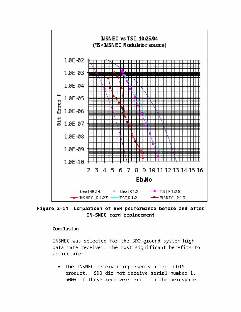
1. The availability of prime and backup buses for each controller provides high performance – this as-delivered configuration doubles the effective rate of the chassis.
2. The Cordata provides additional RAID levels. While the DDS RAIDs have been specified as RAID5, the ability to reconfigure for RAID50 provides a performance improvement option if the repository increases in size (e.g. 60-days versus 30-day file retention).
3. The Cordata cost per TB was the lowest, slightly lower than the Dell/EMC solution.
The DDS team therefore recommended the Cordata RAID at the Ground System CDR Peer Review.
2.2.1.2.3.2 RAID Level Selection
RAID Level - The DDS incorporates RAID as a foundation storage technology for three key functions – the Front End Processing (FEP), Temporary Online Archive Data (TOAD) and the Permanent Online Archive Data (POAD). Together, the data requirements for these functions exceed 65TB in raw storage requirements.
Overview
Because the DDS is unmanned for nominal operations, the storage solution must provide redundancy, single fault tolerance, a degree of load leveling and adequate automatic recovery (‘self-healing” and “failsoft”).
Driving requirements on the storage function include:
DDS Core Mean Time Between Critical Failures (MTBCF) shall be equal to or greater than 20,000 hours23.
Mean Time To Restore Function (MTTRF) shall be less than or equal to 2 hours.
The DDS FEPs shall be capable of replaying stored data at real-time rate based on receipt time. Replays shall not interfere with real time data capture.
The TOAD shall be single fault tolerant. The TOAD shall have a throughput capacity (simultaneous
read/writes) of 300Mbp/s minimum The TOAD shall provide automatic and continuous fault
checking, isolation and correction without loss of data/performance
23 The MTBCF represents the current industry average for storage RAID systems of this size.

A design analysis was performed to identify the best candidate storage system for the DDS. Minimizing data protection risk and retaining expansion options became a priority. The team analyzed all currently available RAID levels.
Analyses
The DDS team collected data from independent sources. A vendor independent description and advantages/disadvantages analysis was performed. The RAID level options were evaluated against the key DDS L4 requirements.
Results
RAID LEVEL
DESCRIPTION BENEFITS DEFICIENCIES
RAID0 Striping - RAID0 adds no redundancy.
Provides the best performance and storage efficiency in I/O intensive environments because there is no parity related overhead. When data is striped, it is spread across several disks with each block of data only being written in one place. The advantage here is not in protection but in performance.
No Data Redundancy; if any of the disks in the stripe fail, then access to all the disks is lost.
RAID1 Mirroring - All of the data on one disk is copied exactly onto a second disk. Neither disk is the master or primary - the disks are peers. For writes to be deemed complete, they must make it to both disks.
Easy to manage and it does not require significant levels of CPU for normal operations or for recovery.
Expense; for every gigabyte of disk to protect, a second, matching gigabyte is needed. RAID1 requires twice as much disk space as unprotected disks.
RAID2 Hamming Code - The same hamming encoding method for checking the correctness of disk data that error correcting code memory (ECC) uses.
RAID level 2 is intended for use with drives that don't have built-in error detection. Since all SCSI drives today have built-in error detection, RAID level 2 is of little use. No commercial implementations of RAID2 were located.

RAID LEVEL
DESCRIPTION BENEFITS DEFICIENCIES
RAID3 Virtual disk blocks – Every write is split (striped) across all of the disks (usually four or more) in the RAID array. Since every write touches every disk, the array can only be writing one block of data at a time
High performance in data intensive applications because data is accessed in parallel. High transfer rates. Larger sequential writes result in better performance
Poor performance in I/O intensive applications because write operations cannot be overlapped due to dedicated parity drive. Small writes scattered all over the disks result in very poor performance
RAID4 Dedicated parity disk - A set of data disks, usually 4 or 5, plus one extra disk that is dedicated to managing the parity for the data on the other disks.
Inexpensive to acquire. High performance in transaction intensive applications that require high read requests because data is accessed independently. High transaction rate.
Write bottleneck. Write operations cannot be overlapped because there is one parity drive. Since all writes must go through the parity disk, that disk becomes a performance bottleneck slowing down all write activity to the entire array
RAID5 Striped Parity - The parity is divided up, with a share being given to each disk in the array
High reliability, high read throughput High performance in small record, multiprocessing environments because there is no contention for the parity disk and read and write operations can be overlapped. No write bottlenecks as with RAID4.
Distributed parity causes overhead on write operations. There is also overhead created when data is changed, because parity information must be located and then recalculated. Slower write-than-read performance, degradation as ratio of writes-to-reads increases
RAID5+0 (RAID50)
Dual Parity Striped - A series of RAID-5 groups striped in RAID-0 fashion
Improves RAID-5 performance without reducing data protection
Additional costs
RAID5+3 Striped Virtual disk Some additional Improvement can be
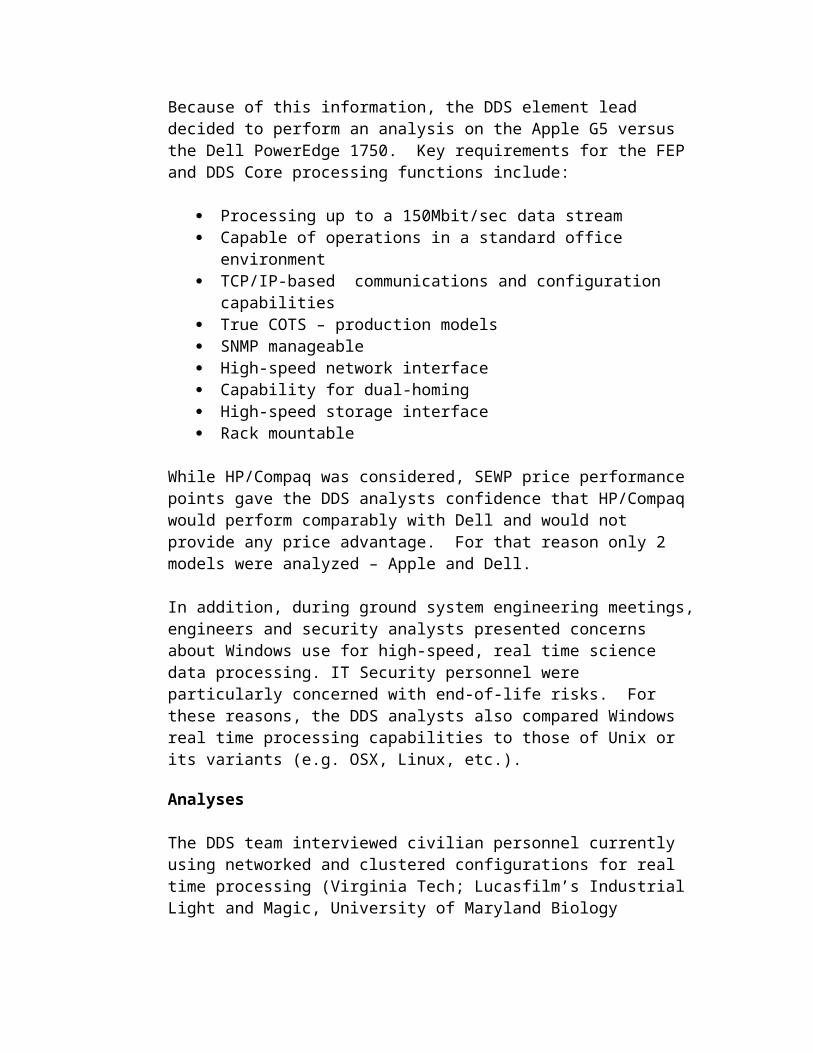
blocks – Misnomer (actually RAID 0+3 in implementation) where RAID3 virtual blocks are then striped
protection insignificant
RAID LEVEL
DESCRIPTION BENEFITS DEFICIENCIES
RAID6 Dual parity - RAID6 takes the striped parity region from RAID5 and duplicates it. Each disk in a RAID6 stripe has two parity regions, each calculated separately.
Even if two disks fail, the RAID stripe would still have a complete set of data and be able to recover the failed disks.
The performance impact of RAID5 is roughly doubled in RAID6 as each set of parities is calculated separately. Where RAID5 requires one extra disk for parity RAID-6 requires two, increasing the cost of the implementation.
RAID7 Trademarked term - by Storage Computer Corporation (SCC). SCC commercial implementation involving SCC proprietary disk array hardware with an internal CPU and a combination of striping and a RAID-5-like model.
RAID1+0(RAID10)
Striping with Mirroring (RAID0+1) -or- Mirroring with Striping (RAID1+0)
High write performance
”Wastes” half the installed drives for data backup
Conclusion
Current Level 4 DDS requirements specify RAID5. Prototype testing, including the Apple RAID in a RAID5 configuration, established the sufficiency of RAID5 performance to meet throughput requirements for the DDS. Therefore the current DDS RAID5 requirement will be met.
The DDS engineering team noted the improved performance for RAID5+0, also known as RAID50. The DDS engineering team added the ability to support RAID50 to the capabilities evaluation. Additionally, preference was given to vendors with dynamic RAID level reconfiguration capabilities.
2.2.1.2.3.3 Windows versus Unix

Operating System – During the early design phase, the question of which operating system to select arose. At this point in the SDO project, the platform selection remained to be made.
Overview
The operating system decision became important as an indicator of which hardware platform would be candidates for the DDS prototype and ultimately the full DDS. The decision to use Unix or a variant provided the most subsequent choices for platforms. The decision to use any version of Windows would limit the platform choices, particularly when high performance capabilities were considered.
Analyses
The DDS engineers (in conjunction with the SDO Ground System Deputy Ground System Manager and the SDO Ground System IT Security lead) selected Windows and 3 Unix variants to evaluate – Solaris, Linux and OSX.
After researching each operating system the evaluation team scored each operating system. Scores were averaged or resolved using a modified Delphi technique.
Results
Table 2–9 DDS OS TRADE STUDY
CRITERIA WEIGHT LINUX(PC) OS/X SOLARIS WINDOWS
PERFORMANCE 5 7 8 8 4PRICE 2 7 9 4 9
STABILITY (COMPANY) 2 8 9 5 10HERITAGE 3 6 6 7 6INTEGRATABILITY 4 5 7 7 5SAN SUPPORT 5 8 10 10 8PORTABILITY 4 7 7 7 3BYTE ORDERING 2 5 10 10 0CUSTOMER SUPPORT 1 5 7 7 5SECURITY 3 7 8 9 3
Raw Total 65 81 74 53Weighted Total 207 251 239 162
Weight: 1 - 5Scores: 1 - 10
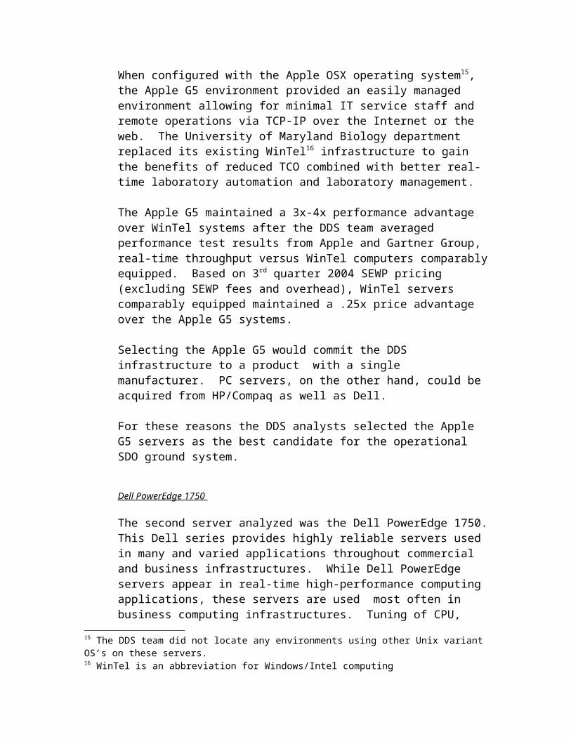
DESCRIPTION REQUIREMENTSPERFORMANCEHow well the OS performs.1. Possible Bandwidth Capacity2. Throughput3. RAM Capacity
DDS DCORE ALL, DDS DQCP ALLDDS DFOP ALL, DDS DVM ALLDDS DRM ALL, DDS DASC ALLDDS DNET ALL, DDS MIS ALL
PRICING.1. Initial Purchase Price2. Customer Support Price3. Upgrade Price
Program Requirements 2.8
STABILITY OF COMPANY.1. How long the company has been in business2. How likely will the company been in business at expected mission end.
Mission Requirements Document 2.2Mission Requirements Document 2.2.1Mission Requirements Document 2.2.2
HERITAGEHow feasible it is to use the OS in the DDS system.1. Past successes using OS in high data applications
Program Requirements 2.8
INTGRATABILITYHow easily the OS can be integrated.1. How well are the hardware drivers supported.2. OS specific interfacing issues
DDS ALL
SAN SUPPORTHow well the OS is supported by various SAN implementations1. Number of SAN Implementations that support the OS
DDS DTOAD ALL
PORTABILITYEase of replacing OS if it becomes unsupported or if it fails to meet requirements.1. Cost to switch to another architecture/OS2. Software portability issues
Program Requirements 2.8
BYTE ORDERBig Endian or Little Endian byte ordering. Big Endian (Network Order) is preferred.
DDS ALL
CUSTOMER SUPPORTHow robust is the company's customer support.1. Hours of customer support2. Did company develop product (product expertise)3. Number of news groups
Program Requirements 2.8
SECURITY FEATURES.1. Inherent firewall capabilities - IP/port blocking, SSH support2. How quickly patches come out when security vulnerabilities are identified3. How frequently system is being hacked
DDS MIS 2.1DDS MIS 2.2
The evaluation team selected Unix. The DDS engineering lead was instructed to select platforms for the prototype and to test the ability of that platform and its associated Unix variant to support the DDS requirements within the SDO mission.

2.2.1.3 Contingency Response
Common and best practices within the data center industry clearly demonstrate that the success or failure of a lights-out or lights dim operations depends to a significant extent on the quality and thoroughness of the automated and automatic contingency responses the system executes.
Because of its unstaffed operations environment, the DDS prioritizes return to science data processing. Thus, at the lowest level, DDS components are not only redundant but most have the ability in hardware, firmware or software to determine a failure has occurred and to immediately either:
Switch to the installed backup component –or- Adjust activities for continued degraded mode operations until a
replacement is provided
Thus science data processing continues without manual intervention required. This self-healing capability provides the fastest response to DDS anomalies; moreover much of this capability is COTS based using industry standard techniques built into the components by the vendors and manufacturers. Most of the Lowest Replaceable Units (LRU) or Lowest Maintainable Units (LMU) within the DDS are self-healing.
The next level brings full system-level redundancy and the ability, based on the operations model, to automatically designate a backup as prime (while demoting the impacted prime) or to expedite the MOC’s authorization of this by providing parallel processing until the swap is complete. In this way operations are ongoing while the fail-soft activity dynamically replaces a failed component with its spare.
Within each function (e.g. QCP, FO, etc.) significant intelligence exists to diagnose and respond to more sophisticated problems. At this level applications (COTS, GOTS and Developed) keep tabs on those functions that supply products to be handled or to whom the function must deliver products. Thus, for example, QCP actively monitors the receipt and quality of science data and has the ability to reconnect or request source data stream connection changes without human interaction or intervention. While the fail-soft level provides for promotion and demotion of systems, in the application activity within the functional level promotion and demotion of entire processing strings could occur. The application activity provides the highest level of automated and automatic response within the DDS. At the top of the function level, contingencies require some human interaction for safety, security or complexity reasons.
Thus DDS concept for contingency response provides a framework for designing a highly reliable unmanned infrastructure.
The DDS handles recovery based on a leveled view of the environment. – The framework creates a hierarchy from the Lowest Replaceable Unit (LRU) or Lowest Maintainable Unit (LMU) through the functional level (e.g. QCP, FO,
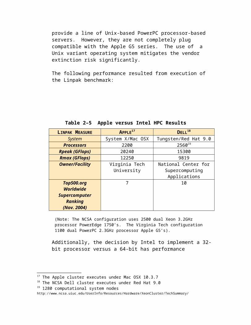
etc.). This allows a variety of automated and auto-recovery responses based on the impact to the science data processing and storage that a given level can inject.
Figure 2-19 DDS Contingency Framework
Within each of these levels, responses are calibrated for potential impact and processes (including escalation approaches) are codified. The framework helps to provide a consistent approach while driving design choices relating to internal system redundancy, choice of hot or warm backup, etc.
Within this framework, responses are tiered. Tiered responses facilitate determination of the man-machine handover point – that point where automated smarts or automatic responses could introduce more problems than they solve and so a human will be contacted. The DDS framework provides for 3 tiers:
Self-Healing – In this tier responses are automated and automatic. System self-detection provides automated failure detection and initiates recovery automatically. Notification of failures occurs as they happen and status changes. Automatic recovery prepares the necessary failure or contingency response but stops short of implementing said response. If the failure/contingency response is approved for automatic initiation, the procedures will be executed by the systems without human intervention. If, however, failure/contingency response initiation has not been approved for automated initiation, the MOC will be informed that all necessary preparatory steps have been completed; the MOC will then initiate the remaining procedures necessary to mitigate the failure/contingency. Result reporting occurs, as expected, post-facto. Permission requests to self-repair do not occur within this tier.

LRU/LMU Level – Self-healing occurs most frequently in the redundancy of components within the discrete equipment and under the control, for the most part, of the operating systems (servers) or management software (SAN, RAID). As an example, with redundant fans, the Apple G5 servers will immediately report and transition if fan performance degradation occurs. Note that this activity could occur before a complete failure by the LRU/LMU.
Systems Level – Self-healing occurs primarily through restart/reboot behaviors by the system in question. These occur without human diagnosis or intervention and seek to maintain the prime system as prime if it can be quickly restored to nominal operations.
Application – Self-healing functionality outside of that built into the COTS is limited to module reloads if an application component fails to respond.
Function – Most self-healing at this level provides for the use of “local smarts”- counters, statistics and other function-generated information used to determine if the function (e.g. QCP) is performing as required. Responses could include –
o Switching to another internal port/data source within the function
o Switching to another port/data source on the prime external system
o Switching to another port/data source on the backup external system
Fail-soft – Self-healing attempts to quickly determine the probable cause of a failure and to respond accordingly. Fail-soft, on the other hand, does not perform diagnosis; rather, as implemented, the fail-soft tier monitors status and, if it detects any detrimental change, immediately demotes the suspected resource and initiates a promotion activity to make the backup the prime (and vice versa). Fail-soft provides the next escalation activity should self-healing be unable to quickly restore nominal DDS operations –
LRU/LMU – For specific LRU/LMU situations the self-healing tier may be skipped for a fail-soft response. The FEP HDR provides such a case. FEP anomalies will result in failover to the backup FEP. This ensures the least impact to science data capture, data throughput and end-to-end DDS throughput.
System – Consistent with its description, fail-soft provides for the immediate reversal of the prime and backup system designation. Simply put: the backup becomes prime and the prime is demoted. Upon return to nominal operations the (former) prime will reinitialize as the new backup.

Application – Both COTS and developed applications will use the function tier for responses.
Function – Similar to the system response, this tier provides for the complete switchover of a function. For example, a QCP could failover to a completely new chain – new FEP, new network connection, new socket, etc. to respond to a failure.
MOC Controlled – Anomalies and failures exist beyond the designed ability of the DDS to invoke either its self-healing or fail-soft approaches. For these events status and alarms will be provided via DSIM to the MOC and the DDS will await MOC action or intervention.
The DDS provides significant amounts of redundancy throughout the design. Redundant components capable of self-correction increase the probability that no data will be lost due to avoidable ground system contingencies, anomalies or failures. Figures 2.20 through 2.24 illustrates how this redundancy supports operations integrity and the 99.99% data capture requirement24.
Error! No topic specified.
Figure 2-20 Baseline DDS – Pre-Failures
In Figure 2.21, a failover to the backup FEP occurs.
Error! No topic specified.
Figure 2-21 FEP Failure and Failover
Note the dynamic reconnection from the QCPs to the backup FEP. This reconfiguration can be automatic from the QCPs, automatic from the DSIM or directed by the MOC via the DSIM.
Error! No topic specified.
Figure 2-22 QCP Failure and Failover
Error! No topic specified.
Figure 2-23 SAN Failure and Failover
Error! No topic specified.
Figure 2-24 FOP Failure and Failover
24 Note that, by requirement, DDS requires only single fault tolerance.

As part of the ground system systems engineering activities, each element performed a Failure Modes and Effects Analysis (FMEA) on its respective element. Table 2-9 provides these results.

Table 2–10 DDS Failure Modes – Real-Time Ka-Band TelemetryGENERAL NOTES :
1. All network components/hardware like: routers, switches, firewalls etc. that are in the DDS are monitored by IPNOC .2. Routers will fail over to backup routers automatically but switches require manual intervention to restore dataflow.3. If any circuit fails, the affect would be same as if the components at either end had failed.4. Definitions:
a. Data Conditionsi. No Data – Data completely missing from channel, media, source etc.
ii. Corrupt Data – Altered data iii. Poor Quality Data – Unreadable or incorrect data within the science data packetiv. Lost Data – Missing blocks anywhere in transmission stream not “recovered” by transmission protocols
b. Data Completenessi. No data received
ii. Some data received1. All good2. Good and bad data3. All bad
iii. All data received1. All good2. Good and bad data3. All bad
c. FMEA – Failure Mode Effect Analysis: a diagnostics process to determine root cause of failures and/or performance degradation(s)5. DDS uses negative event reporting except for status messages specifically required in its specification
SYSTEM FAILURE AFFECT DDS SYSTEM RESPONSE DDS OPERATIONS RESPONSE
FEPsSTGT/WSGT FEP
Single FEP Failure
No DataCorrupt DataPoor Quality DataLost Data
Event message sent to MOC
Ka-band data continues to flow to SOCs from other antenna/FEP site
Analyze QCP & FEP status/information Use MOC-controlled criteria to make FEP replay decision Failover to backup FEP
Automatic command in QCP to read from backup FEP in chain
Manual replacement of failed FEP from active equipment chain
If MOC directed, initiation of FEP replaySTGT/WSGT FEP
Multiple FEP Failure: 1 FEP failure per antenna (2 failed FEPs)
No DataCorrupt DataPoor Quality DataLost Data
Event message sent to MOC
Severity Alert to MOC – 2 of 4 FEPs
Ka-band data continues to flow to SOCs from other antenna/FEP site
Analyze QCP & FEP status/information Use MOC-controlled criteria to make FEP replay decision Failover to backup FEP
Automatic command in QCP to read from backup FEP in chain
Manual replacement of failed FEP from active equipment chain
If MOC directed, initiation of FEP replay
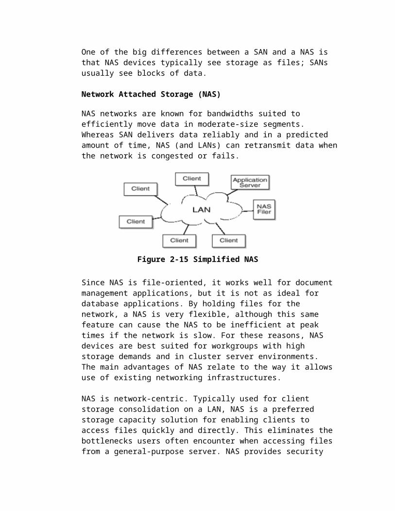
SYSTEM FAILURE AFFECT DDS SYSTEM RESPONSE DDS OPERATIONS RESPONSESTGT/WSGT FEP
Multiple FEP Failure: 2 FEPs failure on a single antenna
No DataCorrupt DataPoor Quality DataLost Data
Event message sent to MOC
Severity Alert to MOC –entire FEP chain
Ka-band data continues to flow to SOCs from other antenna/FEP site
Initiate restoration/replacement of 1 FEP Assist-based command received by QCP to read from 1st
restored FEP If MOC directed, initiation of FEP replay
Initiate restoration/replacement of 2nd FEP on receipt of MOC command
Manual replacement of failed 2nd FEP from active equipment chain
Activate new FEP to active backup mode
Communication – Computer NetworksTCP/IP Gig Ethernet
No DataCorrupt DataLost Data
If DSIM can communicate to MOC, event message sent to MOC with empty status information from DDS functional components
If DSIM CANNOT communicate with the MOC, event change in MOC indicating loss of communications with DSIM/DDS
NO RESPONSE; IPNOC must initiate fault isolation, identification and restoration/recovery of communications service(s).
Continue to store decoded science data stream at FEP Replay from FEP RAID when network restoration is complete
IP Output Network No DataCorrupt DataLost Data
If DSIM can communicate to MOC, event message sent to MOC with empty status information from
NO RESPONSE; IPNOC must initiate fault isolation, identification and restoration/recovery of communications service(s).
Continue to store best-quality science data stream at TOAD If required, replay from FEP RAID when network restoration is
complete

SYSTEM FAILURE AFFECT DDS SYSTEM RESPONSE DDS OPERATIONS RESPONSEDDS functional components
If DSIM CANNOT communicate with the MOC, event change in MOC indicating loss of communications with DSIM/DDS
DDS Core SystemQCP – Prime
1 per instrument
No filesPoor Quality File(s)Missing Data in file(s)
Event message to MOC Aggregated data
quality statistics to MOC
Initiate ONE automatic reconfiguration to alternate FEP stream If problem remains
Automatic promotion command in backup QCPs Failover to backup QCP Demote prime to backup Reinitiate FEP connection
If problem remainso Disable 1 QCP streamo Observe QCP behavior
If problem clears Problem is QCP software Notify MOC of test results Implement MOC-directed response
If problem remains, continue operations responseo Assuming problem is not software based, if no file
received/sent Cross-check FEP status Check with SOC via MOC If FEP is nominal
Assist-based command to QCP to reboot/restore If problem remains
o Activate backup QCP manually o Manually repair/replacement of QCP
o Assuming problem is not software based, if poor quality file(s) is repeatedly written Check if file quality consistent with data quality

SYSTEM FAILURE AFFECT DDS SYSTEM RESPONSE DDS OPERATIONS RESPONSE If quality is consistent, end FMEA process and
report results to MOC If quality is NOT consistent
o Cross-check FEP status If FEPs are nominal
Assist-based command to QCP to reboot/restore
If problem remainso Activate
backup QCP manually
o Manually repair/replacement of QCP
o Assuming problem is not software based, if no file(s) is repeatedly written Cross-check FEP status Cross-check data quality statistics Cross-check Volume Manager Check FEP/VM and data quality for consistency
If quality is consistent, end FMEA process and report results to MOC
If FEP and/or VM are NOT nominal and/or inconsistent with data quality statistics
o Begin MOC-initiated end-to-end analysis

SYSTEM FAILURE AFFECT DDS SYSTEM RESPONSE DDS OPERATIONS RESPONSEQCP - Backup Off
No Processing Event message to MOC Aggregated data
quality statistics to MOC
Determine if QCP-backup has power If powered, determine If QCP is turned on
If turned on but not operationalo Notify MOC of test resulto Manual repair/replacement of QCP-
backup If not turned on, power up and notify MOC of
status If not powered
Notify MOC of power problem If QCP-backup is on but not processing
Notify MOC Implement MOC-directed response Manual repair/replacement of QCP-backup if directed by
MOC
DSIM No status sentPartial status sentCommands abortedCommands incorrectCommands ignored
NONE – no response is symptom
Assist-based command to restore/reboot If DSIM remains impaired
Notify MOC of result [WSC Operator] Promote backup DSIM [WSC Operator] Initiation of DSIM repair/restoration process [WSC
Operator]Permanent Online Archive Device - POAD
Hardware Failure [NOTE: NO SEPARATE SOFTWARE COMPONENTS]
SAN/RAID status POAD failure notice to
DSIM Event message to MOC
Check disk status If disk failure
Hot swap failed disk from uninstalled spares Confirm rebuild from MOC
If problem continues, Check communications networks (LAN) from IPNOC Check VM If LAN and VM are nominal
Check SAN/RAID status If SAN/RAID is nominal
o Use MOC-controlled criteria to make FEP replay decision

SYSTEM FAILURE AFFECT DDS SYSTEM RESPONSE DDS OPERATIONS RESPONSEo Assist-based command from MOC
received by VM to rebooto If problem remains
Manual replacement of failed VM from active equipment chain
If MOC directed, initiation of FEP replay
If SAN/RAID failureo Use MOC-controlled criteria to make
FEP replay decisiono Assist-based command from MOC
received by VM to rebuildo If problem remains
Manual replacement of failed SAN/RAID from active equipment chain
If MOC directed, initiation of FEP replay
If LAN failureo Notify MOC to notify IPNOC
If VM failureo See VM Contingency Section
Temporary Online Archive Device -TOAD
Hardware Failure [NOTE: NO SEPARATE SOFTWARE COMPONENTS]
SAN/RAID status TOAD failure notice to
DSIM Event message to MOC
Check disk status If disk failure
Hot swap failed disk from uninstalled spares Confirm rebuild from MOC
If problem continues, Check communications networks (LAN) from IPNOC Check VM If LAN and VM are nominal
Check SAN/RAID status If SAN/RAID is nominal
o Use MOC-controlled criteria to make

SYSTEM FAILURE AFFECT DDS SYSTEM RESPONSE DDS OPERATIONS RESPONSEFEP replay decision
o Assist-based command from MOC received by VM to reboot
o If problem remains Manual replacement of failed
VM from active equipment chain
If MOC directed, initiation of FEP replay
If SAN/RAID failureo Use MOC-controlled criteria to make
FEP replay decisiono Assist-based command from MOC
received by VM to rebuildo If problem remains
Manual replacement of failed SAN/RAID from active equipment chain
If MOC directed, initiation of FEP replay
If LAN failureo Notify MOC to notify IPNOC
If VM failureo See VM Contingency Section
Volume Manager TOAD data >30 days Missing metadataCorrupt metadataMissing status Archive perf. issues
SAN/RAID status Event message to MOC Best-quality science
data files and meta-data are being written to the TOAD and POAD
Check communications networks (LAN) If LAN is nominal
Check SAN/RAID status If SAN/RAID is nominal
o See FO Contingency Section If SAN/RAID failure
Use MOC-controlled criteria to make FEP replay decision
Assist-based command from MOC received by VM to rebuild
SYSTEM FAILURE AFFECT DDS SYSTEM RESPONSE DDS OPERATIONS RESPONSE If problem remains
o Manual replacement of failed SAN/RAID subsystem from active equipment chain
o If MOC directed, initiation of FEP replay
If data integrity/software failure Use MOC-controlled criteria to make FEP replay
decision Reprocess any outstanding ASFs and/or ARCs
[RM] Restart TOAD=>POAD move routine Restart TOAD cleanup routine
If LAN failure Notify MOC to notify IPNOC
File Output - Prime No files to transmitMissing file(s)Corrupt file(s)
Event message to MOC Aggregated data
quality statistics to MOC
Check communications networks status from IPNOC If communications are impaired
IPNOC command to reboot/restore network devices
If no file is sent repeatedly and communications network is nominal Check for file existence on DDS storage Check file retransmission status If queued for retransmission, end FMEA process, continue
nominal operations Cross-check QCP status Cross-check SAN/RAID Check manually with SOC via MOC If QCP and SAN/RAID are nominal and SOC is
functional Assist-based command to FO to reboot/restore If problem remains
o Activate backup FO manually o Manual repair/replacement of FO
If poor quality file(s) is repeatedly sent Check if file quality consistent with data quality

SYSTEM FAILURE AFFECT DDS SYSTEM RESPONSE DDS OPERATIONS RESPONSE If quality is consistent, end FMEA process and
report results to MOC If quality is NOT consistent
o Cross-check SAN/RAID statuso Cross-check QCP status
If QCP and SAN/RAID are nominal
Assist-based command to FO to reboot/restore
If problem remainso Activate
backup FO manually
o Manually repair/replacement of FO
File Output - Backup
OffNo Processing
Status message to MOC
Aggregated data quality statistics to MOC
Determine if FO-backup has power If powered, determine If FO is turned on
If turned on but not operationalo Notify MOC of test resulto Manual repair/replacement of FO-
backup If not turned on, power up and notify MOC of
status If not powered
Notify MOC of power problem If FO-backup is on but not processing
Notify MOC Implement MOC-directed response Manual repair/replacement of FO-backup if directed by
MOCRetransmission Manager
No DSFNo DSF Processing
Check communications networks status from IPNOC If communications are impaired

SYSTEM FAILURE AFFECT DDS SYSTEM RESPONSE DDS OPERATIONS RESPONSENo ASF RetrievalNo ASF ProcessingNo ARC RetrievalNo ARC ProcessingNo RetransmissionsIncomplete retrans.Incomplete DSF proc.Incomplete ASF proc.Incomplete ARC proc.Missing retrans.
IPNOC command to reboot/restore network devices
If no file is sent repeatedly and communications network is nominal Check for file existence on DDS storage Check file retransmission status If queued for retransmission, end FMEA process, continue
nominal operations Cross-check SAN/RAID Check manually with SOC via MOC If SAN/RAID are nominal and SOC is functional
Automatic promotion command in backup FOo Failover to backup FOo Demote prime to backupo Reinitiate FEP connection
If problem remainso Assist-based command to RM to
reboot/restoreo Manual repair/replacement of RM
If poor quality file(s) is repeatedly sent Check if file quality consistent with data quality
If quality is consistent, end FMEA process and report results to MOC
If quality is NOT consistento Cross-check SAN/RAID status
If SAN/RAID are nominal Assist-based
command to RM to reboot/restore
If problem remainso Activate
backup RM manually
o Manually repair/replacement of RM

SYSTEM FAILURE AFFECT DDS SYSTEM RESPONSE DDS OPERATIONS RESPONSE

2.2.2 External Interfaces
The DDS interfaces the SDO Ground System (SDOGS) antenna system, the Mission Operations Center (MOC) and each Science Operations Center (SOC).
Source Destination DataFlow
DescriptionContents
Transfer Medium/Protocol
Delivery Schedule
Latency Accuracy Data Volume
Document
DDS HMI SOC TLM Science Data
OC-3SCP
Continuous <3min 10-9 55Mbps DDS-SOC ICD
DDS HMI SOC ERR,QAC
Metadata OC-3SCP
Continuous <3min 10-9 1 KB/File
DDS-SOC ICD
DDS HMI SOC DSF Metadata OC-3SCP
1 per hr DDS-SOC ICD
DDS HMI SOC TLM Replay OC-3SCP
At Request 10-9 Varies DDS-SOC ICD
HMI SOC
DDS ARC Metadata OC-3SCP
Daily DDS-SOC ICD
HMI SOC
DDS ASF Metadata OC-3SCP
1 per hr DDS-SOC ICD
DDS AIA SOC TLM Science Data
OC-3SCP
Continuous <3min 10-9 67Mbps DDS-SOC ICD
DDS AIA SOC ERR,QAC
Metadata OC-3SCP
Continuous <3min 10-9 1 KB/File
DDS-SOC ICD
DDS AIA SOC DSF Metadata OC-3SCP
1 per hr DDS-SOC ICD
DDS AIA SOC TLM Replay OC-3SCP
At Request 10-9 Varies DDS-SOC ICD
AIA SOC
DDS ARC Metadata OC-3SCP
Daily DDS-SOC ICD
AIA SOC
DDS ASF Metadata OC-3SCP
1 per hr DDS-SOC ICD

Source Destination DataFlow
DescriptionContents
Transfer Medium/Protocol
Delivery Schedule
Latency Accuracy Data Volume
Document
DDS EVE SOC TLM Science Data
T-3SCP
Continuous <3min 10-9 7Mbps DDS-SOC ICD
DSIM SDOGS SDOGS Directiv
es
SDOGS Control
LANTCP/IP
Real time Real Time
TBD TBD DSIM to GS ICD
SDOGS DSIM Status Antenna Health and
welfare
LANTCP/IP
By Request TBD DSIM to GS ICD
SDOGS DDS RF Science Data Stream
FibreI/F
Continuous Real Time
300 Mbps
MOC DSIM Directives
Directives to DDS/
SDOGS Components
Data Stream Over
SocketTCP/IP
As needed d Real-time As needed N/A DSIM to GS ICD
DSIM MOC Status Status data for health
and monitoring of the DDS and SDOGS
Data Stream Over
SocketTCP/IP
Real-time Continuous
TBD TBD DSIM to GS ICD
Table 2–11 DDS External Interfaces
2.2.2.1 Interface to the SDO MOC
The DDS and SDOGS Integrated Manager (DSIM) interfaces with the Telemetry and Command System in the MOC. The T&C System sends DDS control directives and SDOGS control directives to the DSIM. The DSIM sends DDS status information and SDOGS status information to the T&C System.
For a detailed description and data formats, see Reference 464-GS-ICD-0066, SDO DDS Integrated Manager (DSIM) to Ground System Interface Control Document (ICD).
2.2.2.2 Interface to the SDO SOCs
The DDS transmits best-quality science data files to each SOC (each SOC receives only its own science data) on a continuous basis (24/7). As part of its service assurance, associated QAC files accompany the science data as separate but related files. Finally, on a periodic basis, the DDS sends a recap file (DSF) listing all files sent to a specific

SOC. The DDS also notifies SOCs of files expunged under the 30-day storage requirement using the DSF.
SOCs review the files received and the DSF file. Files received and accepted are listed in the SOC-generated ASF with the status code set to acknowledge. If files have not been received, are not usable (due to transmission issues, not content issues) or have been lost or destroyed, SOCs can request retransmission25 of the processed files using the ASF with the status code set to retransmit.
The ARC captures the status for files moved to hard media (non-TOAD and non-POAD). In a similar manner to the DSF, the ARC is retrieved by DDS on a routine, periodic basis from the SOCs.
Controlled document SDO Interface Control Document (ICD) between the Data Distribution System (DDS) and the Science Operations Centers (SOCs) (464-GS-ICD-0010) provides details on this protocol and its specific functions.
2.2.3 Hardware26
This list aggregates hardware required by the DDS design. Detailed specification information for this equipment can be found in Section 3.
FUNCTION SYSTEM HARDWARE QUANTITY
FRONT END PROCESSOR (FEP)
High Data Rate Receiver
INSNEC Cortex HDR XL 4
FEP VCDU Server Apple G5 Server 4FEP RAID Cordata ATA 4200 RAID
Backplane4
Disk Drives (500GB) 80 (20 per backplane)
QUALITY COMPARE PROCESSING (QCP)
QCP Server Apple G5 Server 6
TOAD/POAD RAID Backplane Cordata ATA 4200 RAID Backplane
5
Disk Drives 500GB SATA one-inch 10K RPM Disk Drives
175
1000BaseT (Gigabit Ethernet) Switch
Vixel 375 Fiber Channel Switch
3
FILE OUTPUT PROCESSING (FO)
FO Server Apple G5 Server 5
25 Note that replay requests (reinsertion and reprocessing of the semi-raw science data captured and stored on the FEP RAID) cannot be directly submitted to the DDS by the SOCs. Replay requests require SOCs to send a request to the MOC. The MOC directs DDS via DSIM to replay a portion of the stored data for reprocessing.26 All equipment EXCEPT accessories (Monitors, mice, etc.) are rack mountable and will be ordered with rack mount kits except as noted.

FUNCTION SYSTEM HARDWARE QUANTITY
DDS-SDOGS INTEGRATED MANAGER (DSIM)
DSIM Server Apple G5 Server 2
SHARED Video Monitor Samsung 17” Dual Analog/LCD Video Monitor
2
Mice Apple Mouse 4Keyboard Apple Keyboard 4Keyboard-Video-Mouse Switch
AutoView 2000R Rack-Mount KVM
3
Rack APC NetShelter 25U 2Rack APC NetShelter 47U 2Rack Power APC Power Distribution Units
AP78505
Network Cabling Belkin – assorted TBD after WSC
InstallationTable 2–12 DDS Hardware – Consolidated List
2.2.4 Network Design
All networks within the DDS are designed, installed, managed and maintained by the NASA GSFC IPNOC. Figure 2.26 illustrates the end-to-end DDS network design.
The DDS uses Gigabit Ethernet throughout for internal communications. Three discrete LANs provide interconnectivity while maintaining security between logical functions and providing ample throughput within the DDS.
The IPNOC provided network access points provide outbound links to the SOCs over dedicated high-speed transmission lines. All communications between the DDS and the SOCs occurs through IPNOC supplied firewalls. Operations and maintenance of these firewalls (status monitoring, rule development and uploads, auditing, testing, etc.) is the responsibility of the IPNOC and is provided as a service to the DDS.
2.2.5 Data Management
The DDS relies on three major repository functions to successfully accomplish its mission.
FEP RAID – The FEP RAID provides real time capture of decoded science data stream as files. Controlled and managed by the FEP VCDU Server, this function makes MOC requested replays possible by storing up to 5-days of FIFO science data. When requested, replays will read from one of these repositories (2 prime and 2 backup) to provide reprocessing and transmission of the reprocessed data. For each FEP, the FEP RAID provides 7TB (usable) of storage connected via

high-speed fiber channel to the FEP VCDU Servers (1 FEP RAID per FEP VCDU Server).
TOAD/POAD – Two functions sharing a single storage CI, the TOAD and POAD provide storage of the processed best-quality science data in files of ~1 minute. Retransmission request sent by the SOCs via the DSF-ASF application-level protocol are satisfied from the TOAD repository. Additionally, the requirement to store quality data and meta data files for the life of the mission will be accomplished by storing these files on the POAD. The TOAD and POAD reside physically on a single 42TB (usable) of storage. By requirement and design, best-quality science data files are expunged automatically after 30 days, thus maintaining a constant sizing for the TOAD.
Operating Storage – Small files used to configure or reconfigure the DDS systems and subsystems reside on the same storage as the TOAD/POAD. As a failsoft, each server has sufficient local storage to retain backup copies of its own configuration files. DSIM status files (incoming and generated) will also use the 42TB storage for their files. Note that DSIM status files are perishable and will be overwritten every TBD UNITS.
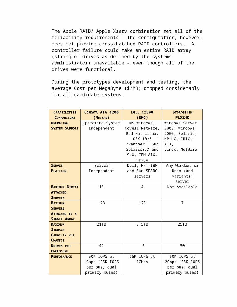
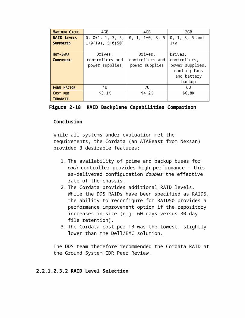
Figure 2-25 DDS Hardware and LAN – Simplified View
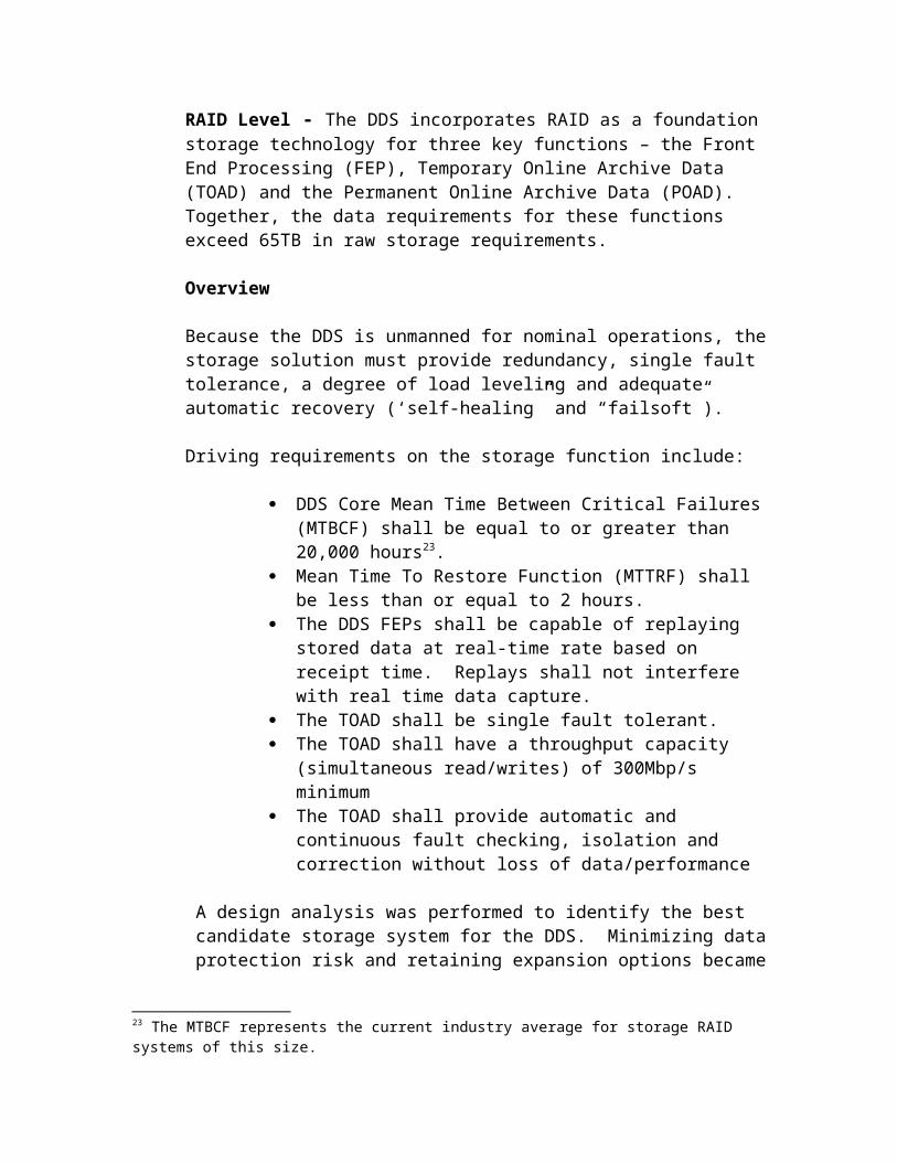

Figure 2-26DDS Network Design – Simplified View
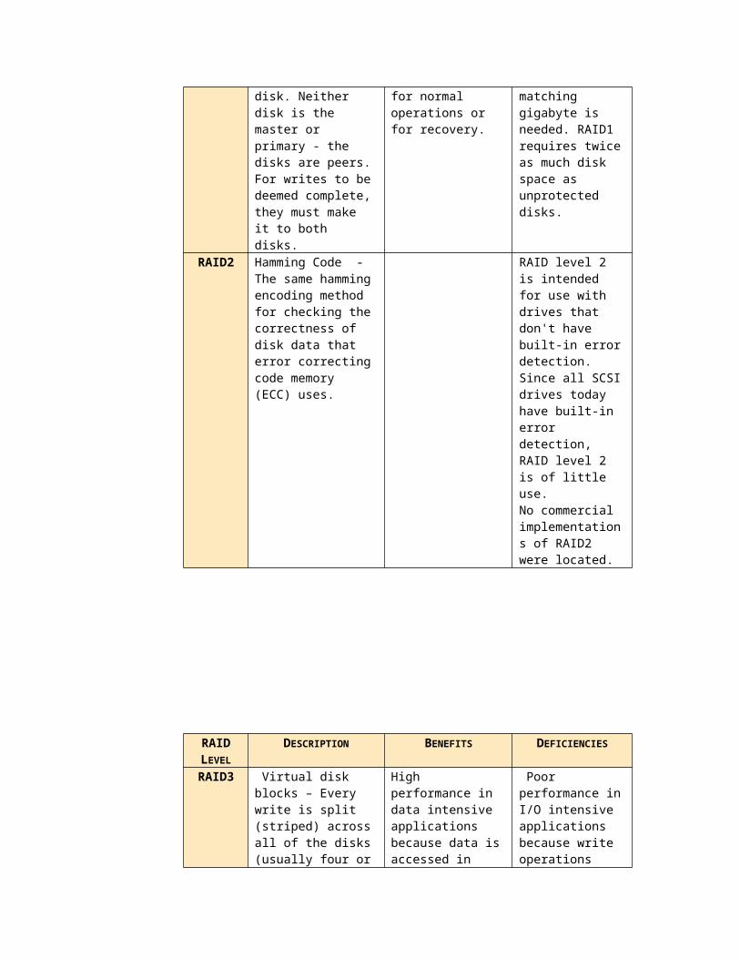
3.0 DDS DESIGN DESCRIPTION
Figure 3-1 illustrates the top-level computer software components (TLCSCs) and the sub-level computer software components (CSCs) that make up the DDS. For each CSC, the illustration indicates if the CSC is a new component, a modified component, or an off-the-shelf component. This section describes the design overview of each top-level software component.
Error! No topic specified.
Figure 3-27 DDS Complete Software CSCIs
3.1 FRONT END PROCESSOR DESIGN
3.1.1 Design Abstract
The FEP hardware consists of two major components, the Front End Hardware and the VCDU Server. The Front End Hardware consists of the Modulator, (for test), Demodulator, Bit Synchronizer, Viterbi Decoder, NRZ-M Decoder, Re-combiner, Frame Synchronizer, PN Decoder and Reed Solomon (RS) Decoder. The VCDU Server consists of an OSX based computer and a 7 TByte RAID capable of storing 120hrs of 150Mbps data.
3.1.1.1 FEP Software
The Front End Processor (FEP) software consists of 2 major components COTS software used to setup the hardware modulator (for test), Demodulator, Bit
Synchronizer, Viterbi Decoder, NRZ-M decoder, Recombiner, Frame Synchronizer, PN Decoder, R-S Decoder. COTS software for the FEP HDR is described in Section 2.2.3.1.1.
Application Software running on VCDU servero fepFW – The File Writer (fepFW) SWCI provides the transfer function
from the socket buffer connected to the FEP receiver to the VCDU high-performance RAID storage. File Writer, while simple in design, plays a critical role in the real-time data processing string; performance of this SWCI affects the ability of the downstream DDS components to meet the DDS processing and delivery requirements to the SOCs.
o fepVS – These SWCIs (fepVS) provide the blocking and preparation of VCDU-tagged files for processing by the QCP. Files are read and blocked into one-minute containers and forwarded to QCP for best-quality determination. As illustrated, this SWCI spawns one instance per instrument.
o fepVM – Like its larger progenitor, this SWCI (fepVM) manages storage quotas for stored data. FEP-VM will delete data over 5 days old from the FEP storage system and report the results to the Status and Control SWCI.
o fepCC – As its name implies the FEP Status and Control (fepCC) SWCI has responsibility for providing status (alerts, counts, confirmations,
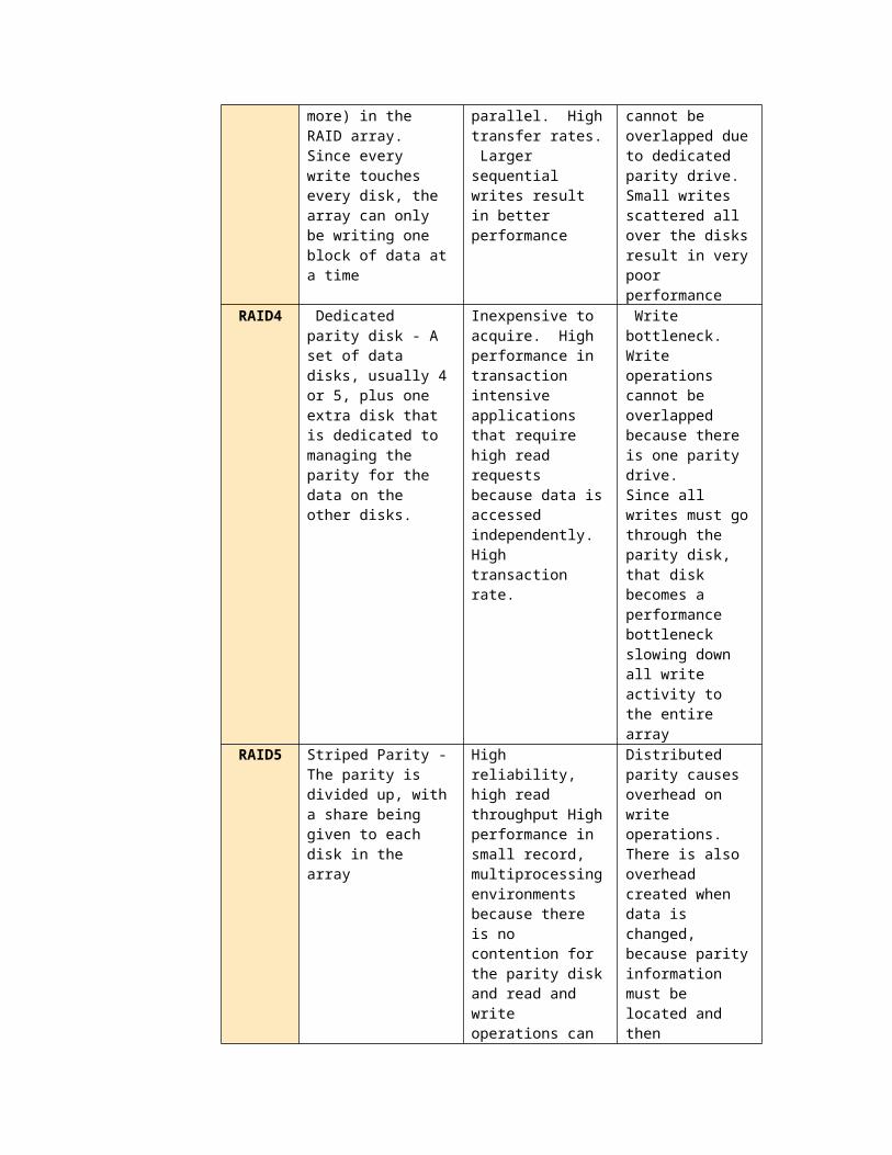
events, statistics, dispensation, responses) to the DSIM for formatting and forwarding to the MOC, as well as responsibility for processing control instructions (directives, commands) from the MOC via DSIM for execution by the FEP as a functional system. Hardware and software CIs report their information to this SWCI for inclusion in a FEP-specific product for the DSIM. For COTS/GOTS hardware and software standard and/or pre-built monitoring points and status data will be exploited where available (e.g. SNMP, etc.).
o fepHdrCC – In a similar manner to fepCC, fepHdrCC provides startup and configuration information for the FEP HDR. FepHdrCC, which executes on the FEP servers, initializes the FEP system using its default configuration file –or- using initialization information from a DSIM directive. This CSCI sets up the High Data-Rate Receiver (HDR), establishes a connection between the FEP server and the HDR and initiates status collection and reporting from the HDR. fepHdrCC also provides self-healing auto-reconnect capability between the FEP server and the HDR.
Figure 3-28 DDS Front End Processor (FEP) CSCIs (excludes HDR)
3.1.1.2 FEP Hardware
fepVMfepFW
(Child)fepVS
(Child)fepVS
(Child)fepVS
Server
Server
Server
fepVS(Parent)
fepCC(Child)
DSIM(Client)
QCP(Client)
QCP(Client)
QCP(Client)
Shared memory
HDR(Server)
client
Server
HDR(Server)
1 MinuteTelemetry Files
client fepHdrCC(Parent)
fepCC(Parent)
Configfiles

Figure 3-29 Front End Processor (FEP) Architecture Overview
3.1.1.2.1 FEP High Data Rate Receiver
INSNEC Cortex HDR XL – The FEP receiver decodes downlinked science data, and outputs the semi-raw science data stream to the FEP VCDU servers. The FEP receiver demodulates a 720MHz IF from the antenna subsystem and outputs 150Mbps data to the FEP VCDU servers.
Prime and hot backup FEP receivers are installed at the STGT facility in the SDO DDS equipment rack. An identical prime and hot backup installation is installed at the WSGT.
Figure 3-30 FEP High Data Rate Recorder Overview
FEP HDR Specification
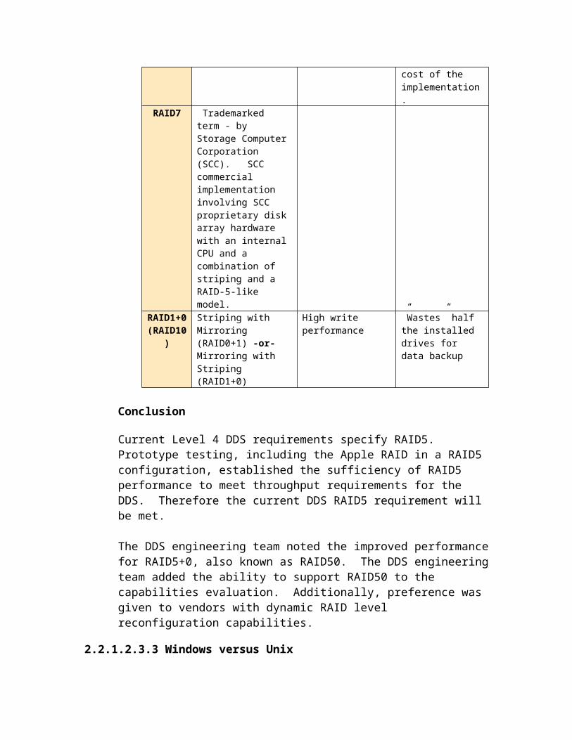
Base Model INSNEC Cortex Series Model HDR-XL
Table 3–13 FEP HDR IF Reception SpecificationIF ReceptionINPUT FREQUENCY 720MHz +/- 200 MHzINPUT PORTS 2INPUT IMPEDANCE 50AGC TIME CONSTANT 1 msIF LEVEL VARIATION = or < 15 dB/secCARRIER ACQUISITION RANGE
+/- 10kHz to =/- 1MHz
IF BANDWIDTH Automatically adjusted from the symbol rate
Table 3–14 FEP HDR Demodulation SpecificationDemodulationDEMODULATION BPSK, QPSK, OQPSK (SQPSK), UQPSK,
8PSK27
CONTINUOUSLY TUNABLE RANGE WITH ONE HDR BOARD
1Mbps to 470Mbps
MAXIMUM SYMBOL RATE BR/2SYNCHRONIZATION THRESHOLD
= or < 1dB (Eb/No)
ACQUISITION TIME = or < 0.25 secondsMAXIMUM DOPPLER RATE <10kHz/secondADDITIONAL FEATURES IF level measurement Doppler measurement
Table 3–15 FEP HDR Bit Error Rate SpecificationBit Rate (Mbps)
BER ~10-2 BER ~10-6
50 <0.1 <0.3105 <0.1 0.3150 0.5 1.0250 0.7 1.3320 0.8 1.7470 <2.0 <3.0
27 Readers should note that the prototype FEP receivers have UQPSK and 8PSK installed. These capabilities are optional and may be dropped from the full procurement.

Table 3–16 FEP HDR Bit Synchronization SpecificationBit Synchronization
ACQUISITION RATE =/- 0.3% of the symbol rateBER DEGRADATION 0.1 to <3 dB28
PCM CODE NRZ-L/M/S, BP-L,DNRZ (for QPSK)MATCHED FILTER I & DOUTPUT PORTS Separate or merged I & Q channels (data and
clock)OUTPUT (ELECTRICAL) ECL or TTLADDITIONAL FEATURES Eb/No measurement
Symbol clock displayTCP/IP data interface (1Gb Ethernet)Frame synchronizationData decoding capability (Viterbi, R-S)
Table 3–17 FEP HDR Mechanical/Electrical Specification
Mechanical/ElectricalPC CHASSIS 7”(H) x 19”(W) x 550mmPOWER SUPPLY Auto-range, 90-265 VAC, 47-63 HzMAXIMUM CONSUMPTION
1.5 A peak, 220 V
OPERATING TEMPERATURE
+10°C to 40°C
STORAGE TEMPERATURE
-20°C to 60°C
RELATIVE HUMIDITY 40% to 90% non-condensing
Cortex Modulator Board (installed option)
Table 3–18 FEP HDR Modulator Board Options Specification – IF Carrier
IF CarrierCARRIER FREQUENCY 720MHz +/- 4 MHzOUTPUT LEVEL 0 to –40 dBm (1-dB steps)
Table 3–19 FEP HDR Modulator Board Options Specification – Noise
28 Degradation depends on the bit rate and noise conditions. See Bit Rate table in this section

Noise SourceNOISE DENSITY -105 to –135 dBm/Hz (1-dB steps)NOISE BANDWIDTH 720MHz +/- 200 MHz
Table 3–20 FEP HDR Modulator Board Options Specification – Modulation
Modulation & Bit RateMODULATION BPSK, QPSK, OQPSK
(SQPSK), UQPSK, AQPSP, 8PSK29
SYMBOL AND BIT RATE See Demodulation table (above)
Table 3–21 FEP HDR Modulator Board Options Specification – PCM Sim
PCM SimulationOPERATING MODE ASCII-coded file or
Pseudo-random patternPSEUDO-RANDOM PATTERN LENGTH
210 , 211, 215, 223
ADDITIONAL FEATURES BER test
3.1.1.2.2 FEP VCDU Server
Apple G5 Dual Processor Server – The FEP VCDU server provides decoded science data receipt, storage, science data stream splitting and output. The FEP VCDU server handles a nominal ~150Mbit/sec data rate end-to-end.
Prime and warm backup FEP VCDU servers are installed at the STGT facility in the SDO DDS equipment rack. An identical prime and warm backup installation is installed at the WSGT for a total of four FEP VCDU serves deployed. In addition, 1 will be supplied for sparing.
Figure 3-31 FEP VCDU Server
FEP VCDU Server Specification
PROCESSOR Dual 2.3GHz PowerPC G5FRONTSIDE BUS 1.15GHz per processorECC MEMORY 1GB PC2300 DDR (400 MHz)MAXIMUM MEMORY 8 GBINSTALLED MEMORY 4 GB
29 Readers should note that the prototype FEP receivers have UQPSK, AQPSP and 8PSK installed. These capabilities are optional and may be dropped from the full procurement

HOT-PLUG STORAGE (SERIAL ATA)
1 drive bays with one 250GB drive
OPTICAL DRIVE Combo Drive (DVD-ROM/CD-RW)NETWORKING 2 on-board 10/100/1000BaseT interfaces,
2 Fiber Channel interfacesPORTS Rear: Two Firewire 800, Two USB 2.0
Front: One Firewire 800MANAGEMENT Built-in hardware-level SNMP-based management and
remote administration support to MacOS (OS 10.3) or other management software
Additional server accessories and peripheral equipment –
MOUSE As supplied by server vendorMONITOR Samsung 17” dual input analog/LCD or comparableVIDEO/MOUSE SWITCH Black Box ServSelect Ultra 16 port KVM switch30
3.1.1.2.3 FEP 7TB RAID
The FEP RAID provides storage of decoded VCDUs in near real time. The FEP RAID consists of:
RAID Backplane – Housing for disk drives and the associated electronics and firmware to configure and operate the RAID. The RAID Backplane also provides the housing for the high-speed fiber channel controllers that connect the RAID to the DDS LAN and the FEP VCDU Servers.
Disk Drives – The RAID Backplane houses the physical drives used for VCDU and file storage.
The DDS design will deploy 2 FEP RAID backplanes – one per FEP VCDU Server at each FEP site. Using the FEP VCDU Server, all backplanes will be live and storing the semi-raw VCDUs from the decoded raw science data stream. In this way data currency can be protected if any swapping of FEP VCDU Servers is required. In addition, any co-located FEP RAID can be connected to any co-located FEP VCDU Server.
The redundant FEP RAID will contain 20 500GB disk drives allocated within each RAID backplane in two “9+1” configurations, with 8GB allocated for main storage and associated parity information and 1GB allocated as hot-swappable in-chassis disk backup. Each FEP RAID consists of 2 redundant controllers each with a prime and a redundant backplane bus. In this configuration, each RAID backplane provides 2 prime data paths of 25000 IOPS each for an aggregate throughput of 50000 IOPS (benchmarked using the iometer public domain benchmarking software).
30 An updated version including the ability to remote control the KVM switch will be available after CDR. The DDS engineer reserves the right to substitute a newer version subject to approval from the ground system management and subject to budget approval as required.

Embedded web-based firmware stores the complete suite of RAID management software. This software provides configuration and operations access to the RAID system.
Figure 3-32 FEP RAID Storage
The FEP RAID connects to the FEP VCDU Server via a redundant fiber channel connection. A switch 1000BaseT connection provides LAN connectivity to the FEP RAID.
Figure 3-33 FEP RAID Storage Communications Configuration

FEP RAID Specification
Cordata RAID BackplaneMAXIMUM SLOTS 42AS CONFIGURED SLOTS 20SYSTEM INTERFACE OS independentCOMMUNICATIONS INTERFACE Fiber Channel,
Gigabit EthernetADDITIONAL FEATURES BER test
Disk Drives (20 drives total)CAPACITY 500GB rawFORM FACTOR SATA-IIINTERFACE DATA RATE 3GbpsDATA INTEGRITY ECC, CRCSUSTAINED DATA RATE 31MBpsERROR RATE (NON-RECOVERABLE) 1 in 1014(31)
3.1.2 External Interfaces
The FEP HDR has a single functional external interface – the SDOGS. The FEP HDR receives 720MHz IF, down-converted from 26.5 GHz Ka-band, demodulates it into science telemetry at ~150Mbps and decodes it. This decoded data is stored on the FEP RAID and transmitted to the DDS QCP function by instrument ID.
The FEP server interfaces DDS internal functions and systems exclusively.
3.1.3 Execution Control and Data Flow
3.1.3.1 FepFW – FEP File Writer
31 Equivalent to 1 in 1 trillion – excludes protection afforded from RAID

Open new file
InitializeShared
Mem
Read fails?
Socket open?
ReadSocket

3.1.3.2 fepVS – FEP VCDU Server
Determine VCids
Open new file
Read annotation
Acceptable quality?
DiscardWrite VCDU &
Annotation
Stop time reached?
Close socket
Write fails?
Socket open?
Determine file time

3.1.3.3 fepVM – FEP Volume Manager

3.1.3.4 fepHdrCC – FEP HDR Command & Control
Initialize
InitializeSHM
Initialize HDR Conn.
InitializeHDR
Request Success?
RequestStatus
Socket Open?
Write to Stats SHM
Directive Received?
Poll DIR SHM
ProcessDirective

3.1.3.5 fepCC – FEP Command & Control
Connect to SHM
Directive Received?
Socket Open?
Write to DIR SHM
Read Socket
Close Socket
EXIT
SendStats
Poll Stats SHM
Poll Resp SHM
StatsAvailable ?
SendResponse
RespAvailable ?
SendStats

3.1.4 Reliability, Fault Tolerance and Failure Response
3.1.4.1 Functional
The FEP function provides high-reliability service through the use of redundant warm in-line configurations at each antenna. A combination of mirrored processing and shared storage allows DSIM directed failover with no data loss and little throughput impact.
Each SDO antenna connects to a prime and a warm-backup FEP. Warm FEPs accept all telemetry as the prime and process and store decoded science data. Warm backups do not provide the separated science data streams to the QCP for best-quality processing. In this manner, any switchover from prime to backup loses no data. The switchover occurs at near 1000BaseT speeds (socket connection) with almost no latency32.
3.1.4.2 Hardware-driven
Within the FEP hardware, significant levels of reliability exist as built-in capabilities of the COTS products:
COMPONENT FAILURE RESPONSEFEP HDR RECEIVER See HDR Operations Manual for specific
failure responsesFEP VCDU SERVER Redundant thermal,
SNMP alerts and auto-degraded mode operations (self-healing)
FEP RAID Backplane: Redundant power, Redundant thermal, Redundant bus, Redundant comm interfaces Redundant firmware Redundant boot loader Hot-swappable drives, SNMP alerts and controlsDrives: ECC-type correction
Within the FEP VCDU servers and FEP RAID, parallel, hot spares are promoted automatically when a component fails33. Within the RAID, all backplane components are redundant and all drives are hot-swappable.
The FEP RAIDs contain 2 hot-swappable spare drives installed in each chassis. Thus the FEP RAID would require 2 drive failures before manual intervention or operator equipment replacement would be required.
32 Each FEP RAID backplane contains 2 redundant controllers. Each controller attaches to 2 redundant backplane bus. Drives inserted into the chassis attach to both backplanes with arbitration by the RAID on-board firmware. Each bus provides 25000 IOPS performance, with 2 buses active nominally for an aggregate 50000 IOPS.33 For the components listed.

3.1.4.3 Software-Driven
The DDS design requires reliability that is not dependent on the DSIM. For this reason the DDS design includes:
Application-generated peer-level “I’m Alive” messages between backups and primes. In the event of a failure, backups can request promotion of themselves and demotion of the former prime from DSIM. If DSIM doesn’t respond with 0.4 minutes, the backup initiates its fail-soft response and performs the promotion/demotion activity, reporting to DSIM post-facto.
Operating/Firmware-based auto-failover within specific components (RAIDs, servers, SAN fabric) – The FEP VDCU servers and the FEP RAIDs contain redundant components within their enclosures. These components failover automatically and autonomously under the control of the operating system and/or firmware. All associated changes and results are reported via SNMP status messages to the system logs and, via the FEP application, to the DSIM.
Custom application-generated statistics with reboot and reload logic within the custom software provides for reboot and reload if a module within the FEP application failures to respond to an interfaced module within 18 seconds.
Cross-functional reconnect capability within the DDS Core. Within the FEP function, the decision to failover from a prime to a backup FEP is made not within the FEP function, but by the QCP function. The rationale behind this placement focuses on ensuring that there is only one data stream per antenna from the FEP function. To accomplish this, each QCP monitors the FEP connections for data. If no data arrives the QCP:
o Notifies the other QCPs to stand down. This ensures that only one QCP controls the FEP switchover.
o Attempts one reconnection to the (current) prime FEPo If that connection fails:
Initiates a connection command for ALL QCPs to the backup FEP. Notifies DSIM of the change.
3.1.4.4 Operations-Driven
The FEP function provides line outage and data loss protection via the replay capability. Simply put, the MOC can initiate replay of up to 5 days of decoded science data telemetry from the FEP RAID storage.
Based on performance testing on the DDS FEP prototype, replay processing will occur at near real time rates with no performance degradation in the FEP VCDU servers, the FEP RAID storage or the associated QCP processors. See Chapter 2 Section 2.2.1.2.1 for the prototype throughput performance results.
3.1.5 Automation

Around-the-Clock autonomous and automated operations by requirement dictated an unmanned design. The FEP HDR, VCDU server and RAID are file driven and configurable via files from the attached consoles or remotely. Directives for function control can be submitted via DSIM. Authorized operators can also rlogin through a secure communications pathway to the system as required. rlogin sessions will be procedure limited to extreme contingencies or during sustaining engineering remote updates/upgrades.
3.2 QUALITY COMPARE PROCESSOR DESIGN
3.2.1 Design Abstract
The Quality Compare Processor will initiate connections to the FEPs, provide setup information to the FEPs at connection initialization and receive VCDUs from up to 3 FEPs simultaneously. In addition, it will create VCDU output files that contain a single VCID per file, ordered by insert zone sequence number. There will be a fixed number of VCDUs per file, each file containing approximately one minute’s worth of data. Duplicate VCDUs will be removed. The Quality Compare Processor will update existing files as reprocessing requires, close files after a predetermined timeout and move closed files to an output directory.
3.2.1.1 Software
The QCP consists of the following software components:
qcpCC – The qcp Command and Control custom application loads at QCP boot and configures the QCP server based on the configuration file contents or based on the content of a DSIM directive. This SW CSCI polls the DSIM system QCP directives, transfers the directives and executes them. This module also polls the shared memory for events, status packets and directive responses by creating the required event, status or DSIM directive response files needed.
qcpClient – qcpClient initiates the required connection per QCP server to the FEP VCDU servers. Additionally this custom application provides the setup information necessary to the FEP VCDU servers for configuration of the end-to-end FEP function. This SW CSCI contains the self-healing reconnection FEP capability and the fail-soft processes for failing to backup FEP resources as required.
qcp – The core application within the QCP function process up to 4 instrument telemetry virtual channels simultaneously and up to 4 error virtual channels per instrument virtual channels. As an output, this application creates the VCDU output files as well as the error VCDU output files (based on pre-defined spacecraft error VC-Ids). As known VCDUs are received, this application compares the newly received VCDUs to those stored by the TOAD, replacing the stored file whenever a received VCDU exceeds the quality of one already stored in the TOAD. This simplifies the qcp process, eliminating the need to hold the first VCDU in memory while awaiting the subsequent arrival of the second. This process also eliminates the error code necessary to handle the contingencies
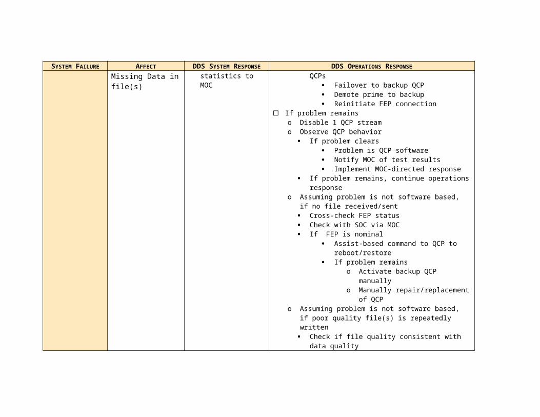
associated with the delayed or non-arrival of the expected VCDU. To maintain throughput, the qcp process closes files with ~1 minute of data or after 10 seconds of elapsed time (whichever comes first). The qcp process generates the QAC files used to provide data quality indication and for DDS service assurance determination. This process also updates the database FileDB that contains a list of every file generated and stored by the QCP function.
qcpClose – This cleanup custom application determines which files have not been accessed for 10 seconds and marks them for closure by the qcp application. Additionally, this process generates status packets at one minute intervals providing such information as:
o Number of VCDUso Number of Error VCDUso Number of missing VCDUso Number and span of gapso Number of files created per day per instrumento Percent completenesso Percent of VCDUs per FEP connection
Figure 3-34 DDS QCP CSCIs
3.2.1.2 Hardware

Apple G5 Dual Processor Server – The QCP server provides decoded science data receipt, storage, science data stream splitting and output. The QCP server handles nominal split telemetry streams of 55Mbit/sec (HMI), 67Mbit/sec (AIA) and 7Mbit/sec (EVE) data rate end-to-end.
3 prime and 3 hot backup QCP servers are installed at the WSGT facility in the SDO DDS equipment rack. Within this configuration any backup can replace any QCP in the DDS Core. In addition, 2 will be supplied for sparing.
Figure 3-35 QCP Server
QCP Server Specification
PROCESSOR Dual 2.3GHz PowerPC G5FRONTSIDE BUS 1.15GHz per processorECC MEMORY 1GB PC2300 DDR (400 MHz)MAXIMUM MEMORY 8 GBINSTALLED MEMORY 4 GBHOT-PLUG STORAGE (SERIAL ATA)
1 drive bays with one 250GB drive
OPTICAL DRIVE Combo Drive (DVD-ROM/CD-RW)NETWORKING 2 on-board 10/100/1000BaseT interfaces,
2 Fiber Channel interfacesPORTS Rear: Two Firewire 800, Two USB 2.0
Front: One Firewire 800MANAGEMENT Built-in hardware-level SNMP-based management and
remote administration support to MacOS (OS 10.3) or other management software
Additional server accessories and peripheral equipment –
MOUSE As supplied by server vendorMONITOR Samsung 17” dual input analog/LCD or comparableVIDEO/MOUSE SWITCH Black Box ServSelect Ultra 16 port KVM switch34
3.2.2 External Interfaces
The QCP has no functional external interfaces – all QCP interfaces terminate at DDS-controlled systems.
34 An updated version including the ability to remote control the KVM switch will be available after CDR. The DDS engineer reserves the right to substitute a newer version subject to approval from the ground system management and subject to budget approval as required.

3.2.3 Execution Control and Data Flow
3.2.3.1 qcpCC – qcp Command and Control
Directive received?
Terminate
Poll DIRdirectory
SendStats
Poll statsSHM
Statsavailable ?
Createstats Pkt
Write to stats dir
SendStats
Poll eventsSHM
Eventsavailable ?
Createevents Pkt
Write to events dir
Poll respSHM
Responseavailable ?
Write to resp dir
Initialize
Get default config
Init config
ReConfig?
Write to DIR SHM
Get New Config

3.2.3.2 qcpClient – qcp Client
Connection successful?
Timeout exceeded?
Switch to alternate
FEP
Write config
to socket
VCDU received ?
Socket open?
Create event
Create event
No data in <1?
Increment incount
outcount =incount?
Switch to alternate
FEP
Close Connection

3.2.3.3 qcp – Quality Compare Process
Same/worseBetter
Initialize
Increment Outcount
Determine VC
Determine index
Error VC?
Write
VCDU exists?
Open idx,tlm,qac
Createidx,tlm,qac
File exists?
Initialize filestructure
Initialize filestructure
File open?
Quality?
Overwite Discard Write
Update idx
Files to close?
Close files
Create qac
Create stats pkt
Update FileDB
Outcount< incount?

3.2.3.4 qcpClose – qcp Close
Initialize
Poll File Structure
Last Update
>10S
Delay 10S
Mark filefor closure
End of open list?
1minutedelay?
BuildStats Pkt
Write to SHM
3.2.4 Reliability and Fault Tolerance Considerations
3.2.4.1 Functional
The QCP function provides high-reliability service through the use of triple redundant hot spares.

Each prime QCP connects to an SDO FEP. Whenever a QCP failure is detected, the hot backups takes over processing in near real-time. The switchover occurs with almost no latency35.
3.2.4.2 Hardware-driven
Within the QCP hardware, significant levels of reliability exist as built-in capabilities of the COTS products:
COMPONENT FAILURE RESPONSEQCP SERVER Redundant thermal,
SNMP alerts and auto-degraded mode operations (self-healing)
Within the QCP servers, parallel, hot spares are promoted automatically when a component fails36.
3.2.4.3 Software-Driven
The DDS design requires reliability that is not dependent on the DSIM. For this reason the DDS design includes:
Application-generated peer-level “I’m Alive” messages between backups and primes. In the event of a failure, primes can request promotion of themselves and demotion of the former prime from DSIM. If DSIM doesn’t respond with 0.4 minutes, the backup initiates its fail-soft response and performs the promotion/demotion activity, reporting to DSIM post-facto.
Connection health determination between the FEP and the QCP falls to the QCP for monitoring. If the QCP identifies a connection loss to the FEP, the specific QCP will attempt re-establishment of the FEP connection (qcpClient responsibility).
Operating/Firmware-based auto-failover within specific components (RAIDs, servers, San fabric) – The QCP servers contain redundant components within their enclosures. These components failover automatically and autonomously under the control of the operating system and/or firmware. All associated changes and results are reported via SNMP status messages to the system logs and, via the QCP application, to the DSIM.
Custom application-generated statistics with reboot and reload logic within the custom software provides for reboot and reload if a module within the QCP application failures to respond to an interfaced module within 12 seconds.
Automated and automatic failover from a prime to a backup QCP. If a prime fails to provide the heartbeat response the backup disconnects the failed QCP from the
35 Each FEP RAID backplane contains 2 redundant controllers. Each controller attaches to 2 redundant backplane bus. Drives inserted into the chassis attach to both backplanes with arbitration by the RAID on-board firmware. Each bus provides 25000 IOPS performance, with 2 buses active nominally for an aggregate 50000 IOPS.36 For the components listed.

connection, establishes its own connection, demotes the failed QCP, updates all necessary status files and reports the results to DSIM.
Cross-functional reconnect capability within the DDS Core. Within the FEP function, the decision to failover from a prime to a backup FEP is made not within the FEP function, but by the QCP function. The rationale behind this placement focuses on ensuring that there is only one data stream per antenna from the FEP function. To accomplish this, the each QCP monitors the FEP connections for data. If no data arrives the QCP:
o Notifies the other QCPs to stand down. This ensures that only one QCP controls the FEP switchover.
o Attempts one reconnection to the (current) prime FEPo If that connection fails:
Initiates a connection transfer command for ALL QCPs to the backup FEP.
Notifies DSIM of the change.
3.2.4.4 Operations Driven
The QCP function supports line outage and data loss protection via the FEP replay capability. Up to 5 days of decoded science data telemetry from the FEP RAID storage can be replayed and reprocessed for best-quality determination by the QCP.
Based on performance testing on the DDS FEP prototype, replay processing will occur at near real time rates with no performance degradation in the QCP servers. See Chapter 2 Section XXXX for the prototype throughput performance results.
3.2.5 Automation
Around-the-Clock autonomous and automated operations by requirement dictated an unmanned design. Like the FEP server s the QCP servers are file-driven and configurable from the attached consoles or remotely or by file execution. Directives for function control can be submitted via DSIM. Authorized operators can also rlogin through a secure communications pathway to the system as required. rlogin sessions will be procedure limited to extreme contingencies or during sustaining engineering remote updates/upgrades.
3.3 TEMPORARY ONLINE ARCHIVE DEVICE DESIGN (TOAD)
3.3.1 Design Abstract
The TOAD provides logical storage for the best-quality VCDU files. The TOAD consists entirely of COTS RAID storage and Storage Area Network (SAN) storage management software. The TOAD physically shares these resources with the Permanent Online Archive Device (POAD) in a single RAID under the management of a single SAN.

As the repository for real-time science data files, the TOAD receives files generated by the QCP and stores them as received. Based on requirements and analyses provided in Chapter 2, the TOAD will nominally store for each instrument:
INSTRUMENT VCIDS PER INSTRUMENT
DATA VOLUME PER MINUTE37, ESTIMATED STORAGE REQUIRED PER 30 DAYS38
AIA 2 140520 VCDUs/File/Minute ~21.7TBHMI 2 115352 VCDUs/File/Minute ~17.8TBEVE 1 29362 VCDUs/File/Minute ~2.26TB
In addition associated index data per best quality VCDU file.
31 days after the first full science data stream begins, the TOAD storage reaches equilibrium – the FIFO-based Volume Manager File Deletion algorithm in the File Output (FO) function deletes files stored more than 30 day earlier. The RAID firmware, SAN software and DSIM receive status on the storage including space available, storage increases/decreases, read/write times per default block size and other industry standard storage performance measures.
Most systems management of the TOAD occurs automatically via scheduled maintenance actions within the RAID and/or SAN management software. Fragmentation management, trending and alerts operate automatically and are reported via the FO to the DSIM for submission to the MOC.
3.3.1.1 Software
As mentioned in the prior section, the TOAD software consists of COTS RAID firmware and SAN storage management software.
The COTS RAID firmware provides drive, backplane and chassis monitoring and status via a web-accessible GUI and includes hardware conditions such as voltages, temperature, battery mode, cache settings, network settings, and blower RPM. Reporting frequency can be configured via the GUI. The firmware generates an event log for all significant events that is then stored on disk. At initialization or first start-up, the array is verified before being put into production. Thereafter, an automatic "parity scrub" (array verify) is performed as a background task every 24 hours. Drive monitoring and reporting includes, for each drive, the complete model name, capacity, serial number, and firmware revision; errors and retries, if any, are also reported.
In addition, the firmware supports the following capabilities at varying response levels (fully automatic to manual intervention required):
N-way mirroring - allows additional mirrors of a data set to be created Array splitting - allows one (or more) of those mirrors to be removed from the
active array
37 Assumes a VCDU size of 1788 bytes38 Note this is approximate – file size could increase or decrease based on data received from the spacecraft.

Array hiding - makes an array invisible to users and the operating system, and accessible only to a privileged administrator
Drive roaming - eliminates the need to keep track of which drives were connected to which RAID controllers
Controller spanning - allows an array to span disks attached to multiple RAID controllers and, in doing so, allows the creation of very large arrays and provides high throughput rates
The SAN software provides intelligent managed shared storage to the DDS clients (entire DDS Core). The SAN software provides the ability to logically combine large-scale physical storage for optimized file-level access. DDS clients use an SAN volume the same as a local disk. Behind the logical view are numerous physical disks combined on several levels using RAID techniques.
The smallest storage element you work within a SAN is a logical storage device called a LUN (a SCSI logical unit number). A LUN represents a group of drives such as a RAID array or a JBOD (just a bunch of disks) device. A LUN is created when an administrator uses the RAID firmware to create a RAID array. The controller hardware and firmware in the RAID system combine individual drive modules into an array based on the RAID scheme chosen. Each array appears on the network as a separate LUN. If the array is divided or “sliced”, each slice appears as a LUN. LUNs are combined to form storage pools. A storage pool in a small volume might consist of a single RAID array, but storage pools in many volumes consist of multiple arrays. Storage pools are then combined to create the volumes that DDS clients see.
The SAN collects and stores metadata about the files on the storage. File system metadata includes information such as which specific parts of which disks are used to store a particular file and whether the file is being accessed. The journal data includes a record of file system transactions that can help ensure the integrity of files in the event of a failure.
Within each storage pool in a volume, the SAN stripes file data across the individual LUNs that make up the storage pool. Performance is improved because data is written in parallel. The SAN Administrator can tune SAN performance by adjusting the amount of data written to each LUN in a storage pool (the “stripe breadth”) to suit a critical application.
SAN administrators can control access to shared volumes in several ways.
Clients cannot browse or mount SAN volumes. Only a SAN administrator can specify which volumes are mounted on which client computers.
Zones in the underlying Fibre Channel network can be used to segregate users and volumes.
Volumes can be mounted with read-only access
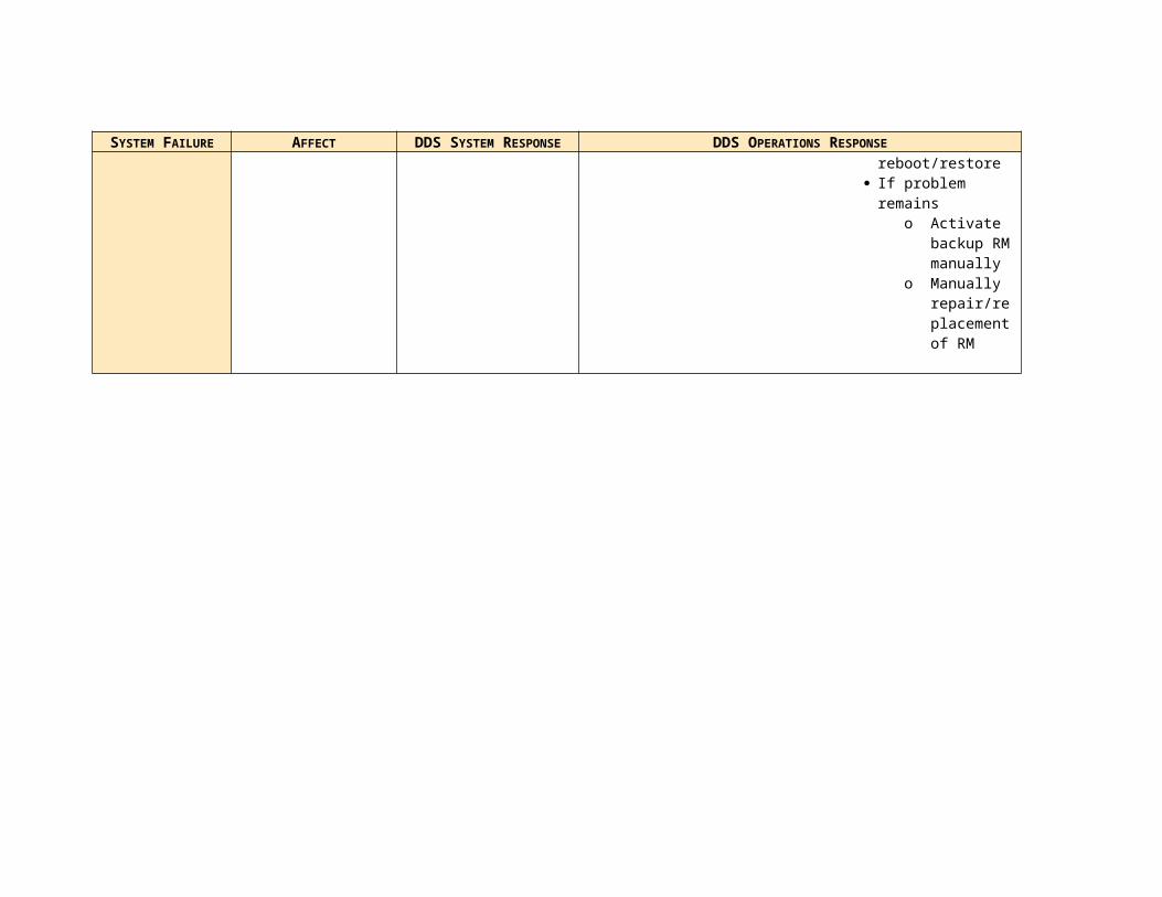
As a large data repository, the TOAD requires sufficient capacities to ensure competent performance and minimal problems from growth-induced errors. The following table lists the key capacities for the DDS Core SAN.
PARAMETER SAN MAXIMUM
NUMBER OF STORAGE POOLS IN A VOLUME 512NUMBER OF LUNS IN A STORAGE POOL 32NUMBER OF LUNS IN A VOLUME 512NUMBER OF FILES IN A VOLUME 4,294,967,296FILE SIZE 16 TBVOLUME NAME LENGTH 70 charactersFILE OR FOLDER NAME LENGTH 251 charactersSAN NAME LENGTH 255 charactersSTORAGE POOL NAME LENGTH 255 characters
Table 3–22 DDS SAN Capacities
3.3.1.2 Hardware
The DDS Core RAID provides storage of best-quality VCDUs in near real time. The DDS Core RAID consists of:
RAID Backplane – Housing for disk drives and the associated electronics and firmware to configure and operate the RAID. The RAID Backplane also provides the housing for the high-speed fiber channel controllers that connect the RAID to the DDS LAN and the FEP VCDU Servers.
Disk Drives – The RAID Backplane houses the physical drives used for VCDU and file storage.
The DDS design will deploy 4 DDS Core RAID backplanes. All backplanes will be live and storing the best-quality VCDUs from the decoded raw science data stream. Data currency occurs independent of the QCP servers. Through the SAN, the DDS Core RAID is connected to all QCP servers (prime and backup).
The DDS Core RAID will contain 42 500GB disk drives per chassis allocated within each RAID backplane in four “40+2” configurations, with 40GB (raw) allocated for main storage and associated parity information and 1GB allocated as hot-swappable in-chassis disk backup. The DDS Core RAID chassis consists of 2 redundant controllers each with a prime and a redundant backplane bus. In this configuration, each RAID backplane provides 2 prime data paths of 25000 IOPS each for an aggregate throughput of 50000 IOPS (benchmarked using the iometer public domain benchmarking software).
Embedded web-based firmware stores the complete suite of RAID management software. This software provides configuration and operations access to the RAID system.
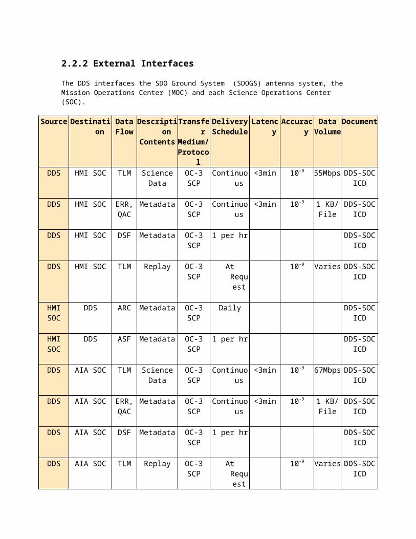
Figure 3-36 DDS Core RAID Storage
The DDS Core RAID connects to the QCP and FO servers via a redundant fiber channel connection. A switch 1000BaseT connection provides LAN connectivity to the FEP RAID.

Figure 3-37 FEP RAID Storage Communications Configuration
DDS Core RAID Specification
Cordata RAID BackplaneMAXIMUM SLOTS PER CHASSIS 42AS CONFIGURED SLOTS PER CHASSIS
42
SYSTEM INTERFACE OS independentCOMMUNICATIONS INTERFACE Fiber Channel,
G-bit EthernetADDITIONAL FEATURES BER test
Disk Drives ( drives total)CAPACITY 500GB rawFORM FACTOR SATA-IIINTERFACE DATA RATE 3Gb/sec DATA INTEGRITY ECC, CRCSUSTAINED DATA RATE 31MBytes/secondERROR RATE (NON-RECOVERABLE) 1 in 1014(39)
39 Equivalent to 1 in 1 trillion – excludes protection afforded from RAID

3.3.2 External Interfaces
For security reasons, the TOAD has no direct external interfaces. Additionally, storage hardware access is controlled and limited by the SAN software.
3.3.3 Execution Control and Data Flow
Not Applicable; COTS hardware and control software only
3.3.4 Reliability and Fault Tolerance Considerations
3.3.4.1 Functional
Functional reliability within the TOAD results from the SAN management. Metadata controller failover protects storage availability from server hardware failure. File system journaling tracks modifications to metadata, enabling quick recovery of the file system in case of unexpected interruptions in service. Fibre Channel multipathing allows file system clients to automatically use an alternate data path in the event of a failure.
3.3.4.2 Hardware-driven
RAID
RAID above the RAID0 level provides protection for the data written to a RAID storage system. The DDS Core will be configured for RAID5, the second highest protection level. The DDS Core RAID can be dynamically reformed into RAID5+040, providing additional performance improvements41. RAID5 striping with parity provides the ability for RAID initiated self-healing should a drive fail. When a drive fails, the RAID controller automatically begins reconstruction of the data using the in-chassis spare.
Within the RAID, all components are redundant – drives (2 hot-swappable spares per chassis), backplane buses into which the drives attach, and RAID controllers.
COMPONENT FAILURE RESPONSEDDS CORE RAID Backplane: Redundant power,
Redundant thermal, Redundant bus, Redundant comm interfaces Redundant firmware Redundant boot loader Hot-swappable drives, SNMP alerts and controlsDrives: ECC-type correction
40 Also known as RAID5041 As noted in the RAID level study in Chapter 2, RAID5+0 price/performance lagged just behind RAID5 in the overhead associated with spindles required and the draw down of raw to usable (~20% for RAID5 versus ~28-30% for RAID5+0)

Hardware drive caching reduces data loss due to failures of a QCP. With drive caching, files transfer is expedited to the cache. The WSC UPS systems provide a “battery backup” to protect the cache from power loss.
3.3.4.3 Software-driven
The SAN provides a journaled file system that will be recovered in seconds in the event of a server failure. Journal data includes a record of file system transactions, eliminating the need for time-consuming integrity checks after an unplanned shutdown of the entire network or of the metadata controller. SAN-managed storage can be back online immediately.
If the metadata controller fails for any reason, the backup FO server takes over. Metadata controller failover is built into SAN software. The SAN software includes both the metadata controller and file system client components. Using the SAN administration tools, the “laws of succession” can be specified - the order in which the SAN metadata controllers take over for a failed controller. These automated and configurable parameters ensure that succession occurs properly, avoiding “split brain,” or multiple conflicting metadata controllers. Once the file system clients “elect” a new metadata controller, the failed system is deactivated until the problem is resolved. The backup FO will serve as a backup standby controller. Using a standby controller enables updates to the SAN software without interrupting DDS service.
The FO server host bus adapters (HBAs) are dual-port cards, providing the server with two connections to the SAN. Fibre Channel multipathing takes advantage of this dual connection: If one Fibre Channel path fails, the SAN continues to use the other for storage access—eliminating a potential single point of failure at the cabling layer. All data paths from the client to the various storage volumes are discovered automatically based on load and availability. This provides two major benefits: Any failure is handled without affecting the user’s work, and all paths are load-balanced to ensure maximum performance and reliability. Multipathing ensures data availability—even if one Fibre Channel path goes down.
3.3.4.4 Operations
A concern from the design reviews has been how the problem of “runaway storage” will be handled. In runaway storage conditions, large amounts of unexpected data get written at rates so quick that the condition could go undetected and/or unresolved, causing the storage to fill completely and the TOAD to fail. The DDS Core SAN has several methods to protect against this possibility.
The first line of prevention, RAID and SAN status reporting provide continuous and early indication of the health and welfare of the storage system. The RAID and SAN report SNMP-based status at intervals as frequently as every 0.5 seconds for specific parameters42. The SAN minimally provides the following health and welfare information:
42 Exact reporting frequency will be determined with the MOC FOT personnel during full end-to-end system testing.

Free space in a volume or storage pool User quota utilization Graphs of processor and network utilization Status of file system processes Log file Connected clients Fibre Channel failures Status of the RAID systems
DSIM receives the above status information via SNMP for summarizing and retransmission to the MOC.
Quotas will be assigned to clients, groups, applications, or any combination of the three. The SAN enforces two types of quotas for each client, group, or application:
Soft Quotas - The soft quota is the maximum space a client or group is expected to occupy on a regular basis. Clients can exceed their soft quota, for a specified grace period only, up to their hard quota.
Hard Quota - The hard quota is an absolute limit on the space a client or group can occupy. Clients are prevented from using more space than specified by their hard quota. Clients or groups can exceed their soft quota provided that they drop below it at some point during the grace period specified. If clients or groups exceed the soft quota for longer than the grace period, the soft quota changes to a hard quota; clients will not be able to save additional data on the volume until old files are deleted and drop below the soft quota.
Quotas are an optional operational feature; they will be implemented after 3 months of full operational periods so that storage and throughput trends can be analyzed to develop appropriate hard and soft quota limits.
Integrity verification (“parity verification”) provides significant preventive measures to protect stored data from unexpected loss. Consistency checks against the disk drive surfaces prevent rebuilds to drives with numerous bad blocks on the media surface. Both integrity verification and consistency checks will be scheduled by the MOC based on performance tuning results during end-to-end system and acceptance testing.
3.3.5 Automation
As discussed in the prior sections, the SAN and RAID administration and operations components provide automated and automatic monitoring, SNMP status reporting (repackaged into CCSDS packets) and first-level failure response (self-healing) from the lowest component level (drives) to the functional level (SAN-based multipathing). Thus much of the TOAD operations require only intelligent review of the supplied monitoring data.

3.4 PERMANENT ONLINE ARCHIVE DEVICE DESIGN (POAD)
3.4.1 Design Abstract
The POAD differs from the TOAD only in the quantity and type of files stored. The POAD retains the QACs, ARCs and file database (FileDB) from the QCP for the life of the SDO mission (prime = 5 years; extended = prime + 5 years). The POAD also houses the source boot and configuration files for each of the DDS Core functions. The POAD estimated size is 12GB; however, to provide for future expansion the POAD has been sized at 1TB. The POAD, like to TOAD, uses the DDS Core storage described in Section 3.3.
3.4.2 External Interfaces
For security reasons, the POAD has no direct external interfaces. Additionally, the raw storage hardware access is controlled and limited by the SAN software.
3.4.3 Execution Control and Data Flow
Not Applicable; COTS hardware and control software only
3.4.4 Reliability and Fault Tolerance Considerations
See Section 3.3.4 in this chapter
3.4.5 Automation
See Section 3.3.5 in this chapter
3.5 FILE OUTPUT PROCESSOR DESIGN (FO)
3.5.1 Design Abstract
The File Output Process (FO) delivers the best-quality files, processed by the QCP and stored in the TOAD, to the SOCs, completing the near real-time science data stream processing obligation for the DDS. Additionally, the FO provides contingency line outage and data recording support by providing the capability to have specific files retransmitted from the TOAD. Finally, the FO manages the DDS Core storage, deleting files older than 30 days and executing the SAN application as the chief node for SAN-based storage management.
foCC
DSIM
DSIM
DSIM
DSIM
foRt
foRe
foRM
Shared MemoryControl Block
tlm
idx
qac
FileDB
err
foVMDirective
Directive Acks
ConfigPackets
Events
StatisticsPackets
ConfigFiles
DSIM
QCP
QCP
QCP
QCP
QCP
ArchivedFileDBs
POAD
TOAD
TOAD
ArchivedARCs
Archived qacs
tlm qac
SOC
tlm qac err
asf arcdsf
Figure 3-38 File Output SW CSCIs
3.5.1.1 Software
The FO consists of 5 SW CIs:
foCC – File Output Command & Control (foCC) is started at system boot by the server operating system. Like the command and control CIs in the other DDS Core functions, this application configures the FO server based on its internal configuration files or a DSIM directive. This application polls for and forwards DSIM directives to the server or the storage system. Additionally this application polls shared memory for events, directive responses and status packets to be forwarded to DSIM.
foRT – File Output Real Time (foRT) has responsibility for the transmission of the best quality science data file and the associated QAC file. Each file pair’s transmission is attempted once based on its status in the FileDB file. This application updates the file pair’s status in FileDB to “SENT”. This application uses the Secure Copy Protocol (SCP) an sFTP variant discussed in the Trade Study section of Chapter 2.
foRM – File Output Retransmit Manager (foRM) provides the automated and automatic ability for SOCs to request retransmission of any best-quality science data file less than 30 days old. The automated/automatic process occurs using a joint-developed application protocol. foRM uses the contents of these files to build the list of files for retransmission in FileDB.
o Every hour on the hour the foRM application generates the DSF – a file containing the delivery status of file transmitted by the foRE application. Once created the files are shipped to the SOCs (1 per SOC).
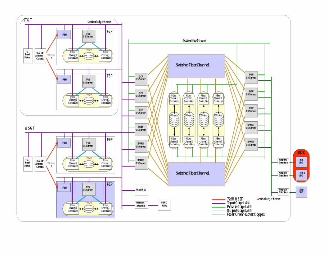
o Upon receipt, the SOC systems reconcile the files in the DSF to their internal storage. This reconciliation results in the ASF – a file listing the SOC’s view of the files from the DSF. SOCs either acknowledge the files from the DSF or request a retransmission of files not received or inaccessible. The foRM application retrieves the ASF every hour on the half hour – exactly 30 minutes after DSF transmission.
o At 15 minutes after midnight GMT the foRM application retrieves the ARC file listing all files archived to hard media within the SOCs. ARC files identify all files safely archived by the each SOC and therefore available for deletion on the TOAD. ARC files are themselves archived for the mission’s life to the POAD.
Retransmission preparation can also be accomplished manually via the MOC. In general, retransmission will be the first service assurance method attempted; SOCs can request a replay if they are dissatisfied with the file quality from the retransmission.
foRE – File Output Retransmission (foRE) uses the file status found in FileDB to retransmit requested files to the SOCs. Like the foRT, this application makes a single attempt to retransmit the requested file pair (telemetry and QAC). If requested, this application has the ability to send an error file with the associated QAC. For consistency of service status, this application also updates the status in the FileDB to “Sent”.
foVM – File Output Volume Manager (foVM) manages the DDS Core storage resources. First and foremost, this application maintains the sizing of the TOAD by deleting best-quality science data telemetry files over 30 days old (FIFO). A collateral capability within this application provides notification at 10 and 25 days to the MOC paging system if a file has not been acknowledged43. Files greater than 45 days old (due to manual intervention by the MOC) are archived and their entries removed from FileDB. All COTS storage management is initiated by this application where possible44.
3.5.1.2 Hardware
Apple G5 Dual Processor Server – The FO server provides delivery of best-quality science data, storage management, and automated/automatic or manual retransmission of stored science data files to the SOCs. The FO completes the near real time throughput service delivery to the SOCs. Additionally, this function manages the DDS Core storage resources (SAN and RAID).
3 prime and 3 hot backup FO servers are installed at the WSGT facility in the SDO DDS equipment rack. Within this configuration any FO backup can replace any FO in the DDS Core. In addition, 2 systems will be supplied for sparing.
43 The MOC generates an email to the appropriate SOC.44 Some COTS applications must be started at boot time by the operating system.
Figure 3-39 FO Server
FO Server Specification
PROCESSOR Dual 2.3GHz PowerPC G5FRONTSIDE BUS 1.15GHz per processorECC MEMORY 1GB PC2300 DDR (400 MHz)MAXIMUM MEMORY 8 GBINSTALLED MEMORY 4 GBHOT-PLUG STORAGE (SERIAL ATA)
1 drive bays with one 250GB drive
OPTICAL DRIVE Combo Drive (DVD-ROM/CD-RW)NETWORKING 2 on-board 10/100/1000BaseT interfaces,
2 Fiber Channel interfacesPORTS Rear: Two Firewire 800, Two USB 2.0
Front: One Firewire 800MANAGEMENT Built-in hardware-level SNMP-based
management and remote administration support to MacOS (OS 10.3) or other management software
Additional server accessories and peripheral equipment –
MOUSE As supplied by server vendorMONITOR Samsung 17” dual input analog/LCD or
comparableVIDEO/MOUSE SWITCH Black Box ServSelect Ultra 16 port KVM switch45
3.5.2 External Interfaces
The FO function interfaces to the external network via the IPNOC-supplied firewalls. Using the SCP protocol, the FO delivers its output to the IPNOC-supplied OC-3 or T-3 ling-haul communications lines.
45 An updated version including the ability to remote control the KVM switch will be available after CDR. The DDS engineer reserves the right to substitute a newer version subject to approval from the ground system management and subject to budget approval as required.

3.5.3 Execution Control and Data Flow
3.5.3.1 foCC – File Output Command & Control
Directive received?
Terminate
Poll DIRdirectory
SendStats
Poll statsSHM
Statsavailable ?
Createstats Pkt
Write to stats dir
SendStats
Poll eventsSHM
Eventsavailable ?
Createevents Pkt
Write to events dir
Poll respSHM
Responseavailable ?
Write to resp dir
Initialize
Get default config
Init config
ReConfig?
Write to DIR SHM
Get New Config
3.5.3.2 foRT – File Output Real Time
NoYes New File?
Initialize
PollFileDB
QAC
Transfer
Delay
Update FileDB
NoYes Transfers successful?
Create Event
TLM Transfer

3.5.3.3 foRM – File Output Retransmit Manager
NoYes
Initialize
CloseFileDB
ReadFileDB
Write toDSF
Status = Sent or Active?
SendDSF
NoYes Transfers successful?
Create Event
Open DSF
Open FileDB
Delay
NoYes FileDB = EOF?
CloseDSF
NoYes
Initialize
CloseFileDB
ReadASF
Close ASF
ASF EOF?
GetASF
UpdateStats
Delay
NoYes Transfers successful?
Create Event
Delete ASF from source
Open ASF
Open FileDB
Delay
Locate in FileDB
Update FileDB
Add to RT list
NoYes Retransmission request?
3.5.3.4 foRE – File Output Retransmission
NoYes List empty?
Initialize
Delay
ReadRT list
tlm transfer
qac transfer
err transfer
Update FileDB
NoYes Transfers successful?
Create Event

3.5.3.5 foVM – File Output Volume Manager
NoYes
Initialize
ReadFileDB
Close FileDB
Remove.tlm err idx
NoYes File >30daysold?
FileDB EOF?
Open Arch FileDB
Delay
qac toPOAD
UpdateStats
OpenFileDB
NoYes File >45daysold?
Copy to Arch FileDB
NoYes File =10 0r 25 days old?
NoYes Status = Sent or Active
Delete from FileDB
CreateEvent
Close Arch FileDB
UpdateFileDB
3.5.4 Reliability and Fault Tolerance Considerations
3.5.4.1 Functional
The FO function provides high-reliability service through the use of triple redundant hot spares. Whenever an FO failure is detected, the hot backups take over processing in near real-time. The switchover occurs with almost no latency46.
3.5.4.2 Hardware-Driven
Within the FO hardware, significant levels of reliability exist as built-in capabilities of the COTS products:
46 Each FEP RAID backplane contains 2 redundant controllers. Each controller attaches to 2 redundant backplane bus. Drives inserted into the chassis attach to both backplanes with arbitration by the RAID on-board firmware. Each bus provides 25000 IOPS performance, with 2 buses active nominally for an aggregate 50000 IOPS.

COMPONENT FAILURE RESPONSEFO SERVER Redundant thermal,
SNMP alerts and auto-degraded mode operations (self-healing)
Within the FO servers, parallel, hot spares are promoted automatically when a component fails47.
3.5.4.3 Software-Driven
The DDS design requires reliability that is not dependent on the DSIM. For this reason the DDS design includes:
Application-generated peer-level “I’m Alive” messages between backups and primes. In the event of a failure, backups can request promotion of themselves and demotion of the former prime from DSIM. If DSIM doesn’t respond with 0.4 minutes, the backup initiates its fail-soft response and performs the promotion/demotion activity, reporting to DSIM post-facto.
Operating/Firmware-based auto-failover within specific components (RAIDs, servers, San fabric) – The FO servers contain redundant components within their enclosures. These components failover automatically and autonomously under the control of the operating system and/or firmware. All associated changes and results are reported via SNMP status messages to the system logs and, via the FO application, to the DSIM.
Custom application-generated statistics with reboot and reload logic within the custom software provides for reboot and reload if a module within the FO application fails to respond to an interfaced module within 12 seconds.
Automated and automatic failover from a prime to a backup FO. If a prime fails to provide the heartbeat response the backup disconnects the failed QCP from the connection, establishes its own connection, demotes the failed FO, updates all necessary status files and reports the results to DSIM.
COTS storage management software provides self-healing and failover capabilities within the FO server.
3.5.4.4 Operations-Driven
The FO function supports line outage and data loss protection via the FO retransmission capability. Up to 30 days of best-quality science data telemetry files with their associated QACs from the DDS Core SAN/RAID storage can be retransmitted to the SOCs.
Based on performance testing on the DDS FO prototype, retransmission processing will occur at near real time rates with no performance degradation in the FO servers. See Chapter 2 Section XXXX for the prototype throughput performance results.
3.5.5 Automation
47 For the components listed.

Around-the-Clock autonomous and automated operations by requirement dictated an unmanned design. Like the FEP and QCP servers the FO servers are file-driven and configurable from the attached consoles or remotely or by file execution. Directives for function control can be submitted via DSIM. Authorized operators can also rlogin through a secure communications pathway to the system as required. rlogin sessions will be procedure limited to extreme contingencies or during sustaining engineering remote updates/upgrades.
3.6 DDS SDOGS INTEGRATED MANAGER (DSIM) DESIGN
3.6.1 Design Abstract
The DDS SDOGS Integrated Manager (DSIM) provides translation between native control and status formats for systems within DDS and SDOGS and the ASIST control environment in the SDO MOC. The DSIM receives status and monitoring information from the native systems, provides translation into ASIST-readable format and forwards the resulting ASIST commands to the MOC for display. A similar translation occurs for status and events – notifications of activity within the SDOGS or DDS48.
Figure 3-40 DSIM SW CSCIs
48 Status provide information concerning routine activities or responses to DSIM directives. Events provide information on anomaly or deteriorating conditions.

3.6.1.1 Software
The DSIM is comprised of the following SW CSCIs:
dsimDIR – DSIM Directive polls shared memory for the arrival of directives. Once a directive is discovered, this application translates the directive as needed by the target SDOGS or DDS system. The SFDU and directive address are used to determine the target system. This application polls the query filter table to provide requested statistics and the response directories as well as shared memory to provide end-to-end responses.
dsimClient – DSIM Client provides TCP/IP-based connection to the SDOGS components (RRCP, ACUs and RF Distribution Assembly) for status and directive transmission. This application attempts automatic reconnection if it senses a connection loss.
dsimSNMP – DSIM SNMP provides similar capability to dsimClient for SNMP manageable systems. This application queries at least once per minute for each SNMP-manageable system and for the DDS Core San and RAID.
dsimMonDat – DSIM Monitor Data polls the shared memory for status and events requiring translation for forwarding to the MOC. Event packet will be sent immediately as SFDUs. Statistics and status will be sent in a multi-packet SFDU at intervals of at least one minute or when the packet size equals 64k bytes.
dsimMonDatSrv – DSIM Monitor Data Server monitors the connection to ASIST in the MOC. If a connection is made, this application then authenticates the connection. If authentication is successful, an acknowledgement is sent and shared memory is polled for any SFDUs that need forwarding.
dsimDirSrv – DSIM Directive Server monitors the connection to ASIST in the MOC. If a connection is made, this application then authenticates the connection. If authentication is successful, an acknowledgement is sent, directives sent are validated and if they are valid, a response is sent.
3.6.1.2 Hardware
Apple G5 Dual Processor Server – The DSIM server translation of MOC-generated ASIST directives to industry-standard control formats and reverse translation from those formats into ASIST-readable packets. This translation function also translates events, status and statistics from SDOGS and DDS system components into an ASIST-usable form.
1 prime and 1 warm backup DSIM server are installed at the WSGT facility in the SDO DDS equipment rack.
Figure 3-41 DSIM Server
DSIM Server Specification
PROCESSOR Dual 2.3GHz PowerPC G5FRONTSIDE BUS 1.15GHz per processorECC MEMORY 1GB PC2300 DDR (400 MHz)MAXIMUM MEMORY 8 GBINSTALLED MEMORY 4 GBHOT-PLUG STORAGE (SERIAL ATA)
1 drive bays with one 250GB drive
OPTICAL DRIVE Combo Drive (DVD-ROM/CD-RW)NETWORKING 2 on-board 10/100/1000BaseT interfaces,
2 Fiber Channel interfacesPORTS Rear: Two Firewire 800, Two USB 2.0
Front: One Firewire 800MANAGEMENT Built-in hardware-level SNMP-based management
and remote administration support to MacOS (OS 10.3) or other management software
Additional server accessories and peripheral equipment –
MOUSE As supplied by server vendorMONITOR Samsung 17” dual input analog/LCD or comparableVIDEO/MOUSE SWITCH Black Box ServSelect Ultra 16 port KVM switch49
3.6.1.3 External Interfaces
The DSIM has no ground system external interfaces; the DSIM interfaces the MOC, DDS and SDOGS.
49 An updated version including the ability to remote control the KVM switch will be available after CDR. The DDS engineer reserves the right to substitute a newer version subject to approval from the ground system management and subject to budget approval as required.
3.6.2 Execution Control and Data Flow
3.6.2.1 dsimClient – DSIM Client
NoYes Monitor DataReceived?
InitializeConnection
Move to SHM
NoYes
Connect to SHM
DirectiveReceived?
Write To Socket
3.6.2.2 dsimDir – DSIM Directive
NoYes Directive Received?
DetermineDestination
NoYes ResponseReceived?
DetermineFormat
Output
FileSHM SHM or File?
DetermineFormat
Output
Poll RespDirs
Delay
NoYes RepsonseReceived?
Poll RespSHM
Output to SHM
Get default config
Init config
NoYes DSIM Directive?
Initialize
Process
NoYes reconfig?
NoYes Query DirectiveTimeout?

3.6.2.3 dsimSNMP – DSIM SNMP
NoYes Anomolous Response?
Initialize
Issue Event
Connect to SHM
Create Packet
Query all Machines
Move PKT to SHM
Delay
3.6.2.4 dsimMonDat – DSIM Monitor Data
NoYes
Poll EventsDir/SHM
NoYes Events Received?
Poll Stats/Statistics SHM
NoYes
Poll Stats/Statistics Dir
Tiime out or buffer full?
Write To SFDU buffer
Build Z Header
Write toSHM
Write To SFDU buffer
Initialize
Connect to SHM
Stats/Statistics Received
Stats/Statistics Received

3.6.2.5 dsimMonDatSrv – DSIM Monitor Data Server
3.6.2.6 dsimDirSrv – DSIM Directive Server

3.6.3 Reliability and Fault Tolerance Considerations
3.6.3.1 Functional
DSIM, by requirement, cannot impact the continued operations of any DDS function. Consequently, while DSIM provides the primary access point for command translation and status interchange between the MOC and the DDS and SDOGS, by design the loss of DSIM will not impact the continued operations of the DDS functions.
3.6.3.2 Hardware-driven
The DSIM shares the same server hardware as all of the DDS functions. Thus it too benefits from the redundancy and the automatic and automated failover built in to the servers.
3.6.3.3 Software-driven
The requirement to isolate DDS function from the loss of DSIM led the designers to provide direct login capabilities within each DDS function. Thus the MOC can remotely access, monitor and command any DDS function. Understandably, MOC data receipt will be impacted as will any trending ongoing when the DSIM fails.
3.6.3.4 Operational
DSIM maintains a warm backup rather than a hot backup. This design choice reflects the concern that duplicated or conflicting command translation be avoided assiduously. The prime and backup DSIM use the previously described heartbeat application-level protocol to determine each others health and welfare. Should the backup DSIM detect the failure of the prime, failover will occur as will initiation of the DSIM application on the backup. Once the functional application has been initiated, all subsequent connections, status collection and reporting are automated.
The MOC has three primary operational options if DSIM fails:
The MOC can request replacement of the failed unit from the onsite, contracted WSGT personnel and, when the DSIM returns to operations, continue MOC control.
The MOC can request replacement of the failed unit from the onsite, contracted WSGT personnel and operations of the DDS until relieved by MOC operations personnel
The MOC can request replacement of the failed unit and operate the SDOGS and DDS via remote access to the functions
MOC procedures will determine under which circumstances each of these options is implemented.

3.6.4 Automation
By specification and design, DSIM operates autonomously, translating instructions into the native command language of the target system while collecting, formatting and sending status information in a MOC-readable format to the MOC operators. As a convenience during failure/contingency operations, the DSIM will provide local screens to allow review of DDS activities during DSIM interactions.

APPENDIX A ABBREVIATIONS AND ACRONYMS
ACRONYM DEFINITION
AIA Atmospheric Imaging AssemblyAIM Advanced Integration ModuleANS Alert Notification SystemAOS Advanced Orbiting SystemsAPI Application Programming InterfaceAPID application idASF Acknowledgment Status FileARC Archive ListASIST Advanced System For Integration & Spacecraft TestingATS absolute time sequenceCAID Control Authority IdentifierCCB Configuration Control BoardCFDP CCSDS File Delivery ProtocolCLCW command link control wordCLTU Command Link Transmission UnitCMO Configuration Management OfficeCOTS commercial off-the-shelfCSC computer software componentCVT current value tableDDS Data Distribution SystemDJT Dirk’s J ToolkitDMR Detailed Mission RequirementsDMZ DeMilitarized ZoneDOS Daily Operations SheetDPS DMZ Product ServerDSF Delivery Status FileDSIM DDS and SDOGS Integrated ManagerDTD Document Type DefinitionEGSE electrical ground support equipmentEPV Extended Precision VectorEVE Extreme Ultraviolet Variability ExperimentFDF Flight Dynamics FacilityFDS Flight Dynamics SystemFEDS Front-End Data SubsystemFEP Front-end ProcessorFF FreeFlyerFMEA Failure Modes and Effects AnalysisFO File Output ProcessorFOT Flight Operations TeamFOV field of viewFSML Flight Software Maintenance LabFSW flight softwareFTP file transfer protocolGOTS government off-the-shelfGPL Gnu Public LicenseGS Ground System
GSFC Goddard Space Flight CenterGUI graphical user interfaceHGA High Gain AntennaHMI Helioseismic and Vector Magnetic ImagerHTTP Hyper Text Transfer ProtocolIAD Interface Agreement DocumentICD Interface Control DocumentIDQ Ingest Data QualityIETF Internet Engineering Task ForceIFS Internal File ServerIIRV improved inter-range vectorIPNOC Internet Protocol Network Operations CenterITPS Integrated Trending and Plotting SystemJBOD Just a Bunch of DisksJDBC Java Database ConnectivityL&EO Launch and Early OrbitLASP Laboratory for Atmospheric and Space PhysicsLMSAL Lockheed-Martin Solar and Astrophysics LaboratoryLTT lifetime trendMAR Mission Analysis RoomMOC Mission Operations CenterMPS Mission Planning SystemMOU Memorandum of UnderstandingMRD Mission Requirements DocumentNAS Network Attached StorageNASA National Aeronautics and Space AdministrationOS operating systemPDB project databasePDU power distribution unitPSLA Project Service Level AgreementQAC Quality Accounting CapsuleQCP Quality Control Processor or ProcessRAID Redundant Array of Independent / Inexpensive DisksRAM random access memoryRDL Record Definition LanguageRMA Reliability, Maintainability and AvailabilityRTS Relative Time SequenceSAN Storage Area NetworkSBC single board computerSCLG stored command load generatorSCM Service Control ManagerSCP Secure Copy ProtocolSDO Solar Dynamics ObservatorySDOGS Solar Dynamics Observatory Ground StationSECSH Secure Shell (IETF nomenclature)SFDU standard formatted data unitSFID self IDsFTP Secure FTPSN Space NetworkSNUG Space Network Users GuideSOC Science Operations Center
SSL Secure Socket LayerSTK Satellite Tool KitSTOL spacecraft test and operations languageSW softwareT&C Telemetry and CommandTBD to be definedTBS to be specifiedTCP Transmission Control ProtocolTDQ Telemetry Data QueryTLCSC top-level computer software componentTSM telemetry statistics monitorUSN Universal Space NetworkUTDF Universal Tracking Data FormatUUEE Universal Execution EngineVCDU virtual channel data unitWIntel Windows/Intel platformWSC White Sands ComplexWSGT White Sands Ground TerminalXML Extensible Markup Language