dd ec-1 - hilti usa · 2 dd ec-1 3 300 0 150 4 5 300 0 150 dd ec-1 6 9 7 8 printed: 02.12.2013 |...
TRANSCRIPT

Operating instructions enMode d’emploi frManual de instrucciones es
DD EC-1
Printed: 02.12.2013 | Doc-Nr: PUB / 5163253 / 000 / 01
DD EC-1
1� � �
�� �
�
� � ��
� �
� �
�
�
�
�
�
�
Printed: 02.12.2013 | Doc-Nr: PUB / 5163253 / 000 / 01

This Product is CertifiedCe produit est certifié
Este producto esta certificadoEste produto está certificado
C US
Printed: 02.12.2013 | Doc-Nr: PUB / 5163253 / 000 / 01

2
DD EC-1
3
300
0150
4 5
300
0150
DD EC-1
6
9
7
8
Printed: 02.12.2013 | Doc-Nr: PUB / 5163253 / 000 / 01

DD EC-1
10
1 2
DD EC-1
11
35
DD EC-14
12
DD EC-1
14
16
DD EC-1
15
0,5mm
13
> 0.5 mm> 1/16″
Printed: 02.12.2013 | Doc-Nr: PUB / 5163253 / 000 / 01

DD EC-1DD EC-1
54
DD EC-1
DD EC-123
117
18
19 20
22 2321
Pos. 1 Pos. 2
Printed: 02.12.2013 | Doc-Nr: PUB / 5163253 / 000 / 01

1
In these operating instructions, this symbol indi-cates points of particular importance to safety. The
instructions at these points must always be observedin order to reduce risk of serious injury.
Caution: electrical� The numbers refer to the illustrations on the fold-outcover pages (front and rear cover).
� / � The numbers refer to the operating controls /component parts of the tool.
In these operating instructions, the electric tool to whichthese operating instructions apply is referred to as “thetool”.
It is essential that the operatinginstructions are read before thetool is operated for the first time.
Always keep these operatinginstructions together with the tool.
Ensure that the operating instructions are with the tool whenit is given to other persons.
Contents PageOperating controls and component parts 1General safety rules 2Specific safety rules and symbols 3Description 4Technical data 4Main features of the tool 5Intended uses 5Before use 5Assembly 6Operation 6Care and maintenance 8Insert tools and accessories 8Manufacturer's warranty – tools 8Disposal 9Troubleshooting 10
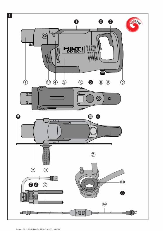
Operating controls �� Chuck operating lever� Control switch� Water flow control knob� Switch lock� Electric supply cord plug connection
(supply cord socket)� Water collector holder release button Slider for water collector holder rod length
adjustment Water collector ring� Depth gauge� Water level indicator release button
Component parts �� Chuck Pressure plate� Side handle� Gearing section with TOPSPIN kinematics� Motor� Grip� Water flow indicator� Circular bubble level� Cylindrical bubble level� Type / rating plate� Belt drive cover� Water collector holder rods� Water collector seal ring� Supply cord
ORIGINAL OPERATING INSTRUCTIONS
DD EC-1 diamond core drilling machine
1_BA_DDEC_1_P3_en.qxp:1_BA_DDEC_1_P3_en 16.10.2013 10:17 Uhr Seite 1
Printed: 02.12.2013 | Doc-Nr: PUB / 5163253 / 000 / 01
2
General safety rules
SAVE THESE INSTRUCTIONS
2. Work Area2.1 Keep your work area clean and well lit. Clutteredbenches and dark areas invite accidents.2.2 Do not operate power tools in explosive atmos-pheres, such as in the presence of flammable liquids,gases, or dust. Power tools create sparks which mayignite the dust or fumes.2.3 Keep bystanders, children and visitors away whileoperating a power tool. Distractions can cause you tolose control.
3. Electrical Safety3.1 Grounded tools must be plugged into an outlet properly installed and grounded in accordance withall codes and ordinances. Never remove the ground-ing prong or modify the plug in any way. Do not useany adaptor plugs. Check with a qualified electricianif you are in doubt as to whether the outlet is proper-ly grounded. If the tools should electrically malfunc-tion or break down, grounding provides a low resis-tance path to carry electricity away from the user.3.2 Avoid body contact with grounded surfaces suchas pipes, radiators, ranges and refrigerators. Thereis an increased risk of electric shock if your body isgrounded.3.3 Don’t expose power tools to rain or wet con di -tions. Water entering a power tool will increase the riskof electric shock.3.4 Do not abuse the cord. Never use the cord to car-ry the tools or pull the plug from an outlet. Keep cordaway from heat, oil, sharp edges or moving parts. Replace damaged cords immediately. Damaged cordsincrease the risk of electric shock.3.5 When operating a power tool outside, use an out-door extension cord marked «W-A» or «W». Thesecords are rated for outdoor use and reduce the risk ofelectric shock.
4. Personal Safety4.1 Stay alert, watch what you are doing and use common sense when operating a power tool. Do notuse a tool while tired or under the influence of drugs,alcohol, or medication. A moment of inattention whileoperating power tools may result in serious personalinjury.
4.2 Dress properly. Do not wear loose clothing or jewelry. Contain long hair. Keep your hair, clothing,and gloves away from moving parts. Loose clothes,jewelry, or long hair can be caught in moving parts.4.3 Avoid accidental starting. Be sure switch is off before plugging in. Carrying tools with your finger onthe switch or plugging in tools that have the switch oninvites accidents.4.4 Remove adjusting keys or wrenches before turning the tool on. A wrench or a key that is left attached to a rotating part of the tool may result in per-sonal injury.4.5 Do not overreach. Keep proper footing and bal-ance at all times. Proper footing and balance enablesbetter control of the tool in unexpected situations.4.6 Use safety equipment. Always weareye protection. Dust mask, non-skid safe-ty shoes, hard hat or hearing protectionmust be used for appropriate conditions.4.7 Exercise your fingers during pauses between workto improve the blood circulation in your fingers.
5. Tool Use and Care
5.1 Use clamps or other practical way to secure andsupport the workpiece to a stable platform. Holdingthe work by hand or against your body is unstable andmay lead to loss of control.5.2 Do not force tool. Use the correct tool for yourapplication. The correct tool will do the job better andsafer at the rate for which it is designed.5.3 Do not use tool if the switch does not turn it on oroff. Any tool that cannot be controlled with the switchis dangerous and must be repaired.5.4 Disconnect the plug from the power source be -fore making any adjustments, changing accessories,or storing the tool. Such preventive safety measuresreduce the risk of starting the tool accidentally.5.5 Store idle tools out of reach of children and otheruntrained persons. Tools are dangerous in the handsof untrained users.5.6 Maintain tools with care. Keep cutting tools sharpand clean. Properly maintained tools with sharp cut-ting edges are less likely to bind and are easier to con-trol. 5.7 Check for misalignment or binding of moving parts,breakage of parts and any other condition that mayaffect the tools operation. If damaged, have the toolserviced before using. Many accidents are caused bypoorly maintained tools.5.8 Use only accessories that are recommended bythe manufacturer for your model. Accessories thatmay be suitable for one tool may become hazardouswhen used on another tool.
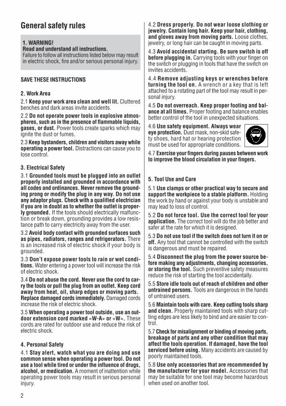
1. WARNING!Read and understand all instructions. Failure to follow all instructions listed below may resultin electric shock, fire and/or serious personal injury.
1_BA_DDEC_1_P3_en.qxp:1_BA_DDEC_1_P3_en 16.10.2013 10:17 Uhr Seite 2
Printed: 02.12.2013 | Doc-Nr: PUB / 5163253 / 000 / 01

3
Read the operatinginstructions.
Always wear eye protection. Always wear protectiveclothing.
Always wear protectivegloves.
Use protectiveequipment.
6. Service6.1 Tool service must be performed only by qualifiedrepair personnel. Service or maintenance performedby unqualified personnel could result in a risk of injury.
6.2 When servicing a tool, use only identical replace-ment parts. Follow instructions in the Maintenancesection of this manual. Use of unauthorized parts orfailure to follow Maintenance Instructions may create arisk of electric shock or injury.
Check the tool each time before use.Check the condition of the tool, the supply cord,
power plug and hoses. Don't use it if it is damaged,incomplete or if the controls cannot be operated cor-rectly. If parts are damaged or missing, have the toolrepaired at an authorized Hilti service center.
Use the correct insert tool.Ensure that the core bits are equipped with the appro-priate connection end for the chuck system in use andthat they are locked in position correctly in the chuck.Use only the recommended original Hilti accessoriesand auxiliary equipment.Use the tool only for the purposes for which it is intended.
Apply a safe working method.Avoid unfavourable body positions. Always ensure
that you have a safe and stable stance. Always holdthe tool in both hands when it is in use. Always usethe side handle. Ensure that the side handle is fittedcorrectly and tightened securely �.Hold the tool securely when drilling and pay attentionat all times. Switch the tool off if you are distractedfrom your work.
When the tool is in use, always guide the supplycord away from the tool to the rear.
Never carry the tool by the supply cord. Don't unplugthe tool by pulling on the supply cord. Don't exposethe supply cord to heat, oil or sharp edges. If the sup-ply cord becomes damaged while working, don't touchit – unplug the power plug immediately.Check that the blades of the plug and supply cord areclean and dry before it is connected. Unplug the sup-ply cord form the power socket before cleaning.
Drilling through reinforcing barsObtain permission from thearchitect or site engineerbefore drilling through rein-forcing bars. Drilling through
steel is indicated by slow progress and clear water atthe core bit.
Take care to avoid concealed cables and pipes.Concealed electric cables or gas and water pipespresent a serious hazard if damaged while youare working. Accordingly, check the area inwhich you are working beforehand (e.g. using
a metal detector). Avoid contact between your bodyand grounded objects such as pipes or radiators. Exter-nal metal parts of the tool may become live, for exam-ple, when an electric cable is drilled into inadvertently.The power to cables (or water, gas etc. in pipes) locat-ed where drilling work is to take place must be switchedoff.
Avoid unintentional starting.Do not carry the tool with your finger on the controlswitch while it is connected to the power supply. Checkthat the tool is switched off and that the trigger switchlockbutton is released before connecting it to the pow-er supply or before connecting the supply cord to thetool. Disconnect the plug from the power socket whenthe tool is not in use, e.g. during pauses between work,before maintenance and when changing insert tools.
Keep the electric tool and insert tools in goodcondition.
Follow the care and maintenance instructions andreplace insert tools in good time. Never operate thetool when it is dirty or wet. Dust or dampness on thesurface of the tool make it slippery and difficult to holdand may, under unfavourable conditions, present a riskof electric shock.Repairs to the tool may be carried out only by an autho-rized electrical specialist using original Hilti spareparts. Failure to observe this point may result in dam-age to the tool or present a risk of accident. According-ly, if necessary, have the tool repaired at a Hilti servicecenter or authorized Hilti repair workshop.
When setting anchors, follow all anchor instal-lation instructions and applicable testing / inspec-tion regulations.
Store the tool in dry area if it is not in use.Symbols used on the tool:
Specific safety rules and symbols
1_BA_DDEC_1_P3_en.qxp:1_BA_DDEC_1_P3_en 16.10.2013 10:18 Uhr Seite 3
Printed: 02.12.2013 | Doc-Nr: PUB / 5163253 / 000 / 01
4
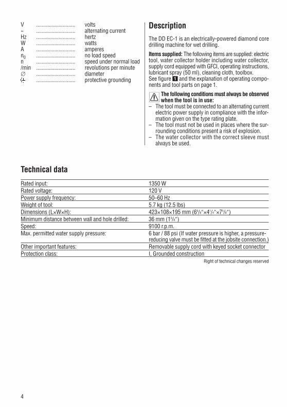
Technical data
Rated input: 1350 WRated voltage: 120 VPower supply frequency: 50–60 HzWeight of tool: 5.7 kg (12.5 lbs)Dimensions (L×W×H): 423×108×195 mm (65/8″×41/4″×75/8″)Minimum distance between wall and hole drilled: 36 mm (13/8″)Speed: 9100 r.p.m.Max. permitted water supply pressure: 6 bar / 88 psi (If water pressure is higher, a pressure-
reducing valve must be fitted at the jobsite connection.)Other important features: Removable supply cord with keyed socket connectorProtection class: I, Grounded construction
Right of technical changes reserved
V ............................ volts~ ............................ alternating currentHz ............................ hertzW ............................ wattsA ............................ amperesn0 ............................ no load speedn ............................ speed under normal load/min ............................ revolutions per minute∅ ............................ diameter
............................ protective grounding
DescriptionThe DD EC-1 is an electrically-powered diamond coredrilling machine for wet drilling.
Items supplied: The following items are supplied: electrictool, water collector holder including water collector,supply cord equipped with GFCI, operating instructions,lubricant spray (50 ml), cleaning cloth, toolbox.See figure � and the explanation of operating compo-nents and tool parts on page 1.
The following conditions must always be observedwhen the tool is in use:
– The tool must be connected to an alternating currentelectric power supply in compliance with the infor-mation given on the type rating plate.
– The tool must not be used in places where the sur-rounding conditions present a risk of explosion.
– The water collector with the correct sleeve mustalways be used.
1_BA_DDEC_1_P3_en.qxp:1_BA_DDEC_1_P3_en 16.10.2013 10:18 Uhr Seite 4
Printed: 02.12.2013 | Doc-Nr: PUB / 5163253 / 000 / 01

5
The position and dimensions of the holes drilled mustbe approved by the design engineer, architect or personin charge of the building project (building statics).
Before useIt is essential that the safety precautions print-ed in these operating instructions are read
and observed.
The power voltage must correspond to the infor-mation on the type rating plate.
If extension cables are used: Only extension cablesof a type approved for the intended use and of ade-
quate cross section may be used. Failure to observe thispoint may result in reduced performance and could causethe cable to overheat. Damaged extension cables mustbe replaced. The recommended extension cord AWG size maximumand maximum lengths are:Extension Cord Table
Conductor cross-sectionVoltage 1.5 mm2 2.5 mm2 14 AWG 12 AWG110–120 V 20 m 40 m 100 ft 150 ft
Before beginning drilling, ensure that the nec-essary safety rules are observed to preventinjury or damage caused by falling cores or
water escaping from the hole into rooms or areas belowwhere the holes are being drilled.
Before using the tool, ensure that the chuck is cleanand the core bit to be used is not damaged (e.g.
the core bit must not wobble or run out of true when thechuck lever is closed). Worn or broken parts on the elec-tric tool or core bit must be replaced immediately.
When drilling overhead, for safety reasons,the following items of equipment must be
used:1. Water collector assembly with suitable water collec-
tor seal ring2. DD-REC1 water recycling system, or3. A suitable wet-type vacuum cleaner with the correct
adaptor for the water collector hose4. Ground fault circuit interruptor (GFCI) (integrated in
the supply cord)
Use only DD-C core bits.
Do not apply excessive pressure when drilling. This willnot increase drilling performance.
Only pure water, without additives, may be used for cool-ing and flushing when drilling. Use of the liquids listedin the DD-REC1 operating instructions is permissible
Main features of the tool– Drilling machine with TOPSPIN kinematics, i.e. delib-
erate orbital movement of the core bit and chuck– Class I electrical protection– Belt drive (uses no oil)– Mechanical slip clutch– Electronic motor protection– Rubber-covered grip and side handle– Chuck system for DD-C core bits (150 and 300 mm /
6″ and 12″ effective core depth)– Quick-change core bit connection end system– Infinitely variable speed control– Automatic water on / off function– Manual water volume regulation– Built-in water flow rate indicator– Lockable trigger switch– Removable water collector holder– Removable supply cord with keyed socket connector
and GFCI ground fault circuit interruptor– Depth gauge– Bubble levels
Intended usesThe tool is intended for the following uses:– Drilling holes (diamond core drilling) of 10–35 mm
(3/8″–15/16″) diameter in reinforced concrete, mason-ry and natural stone.
– To be used exclusively for wet drilling and in con-junction with the water collector and correspondingwater collector seal rings.
– The tool must be connected to a power supply pro-viding a voltage and frequency in compliance with theinformation given on the type rating plate.
– The tool may be used only when connected to a pow-er supply equipped with a ground conductor and ofadequate power rating.
– The tool may be used only with the power supply cordsupplied with the tool, which is equipped with a keyedsocket connector and built-in GFCI.
– In accordance with national safety regulations, thesafety function of the ground conductor must be test-ed at regular intervals.
– Before use, the GFCI must be tested for correct func-tionality.
– Only the core bits and accessories designed for usewith this tool may be used.
The tool may be handled only as described in these oper-ating instructions (care, maintenance, assembly, use,etc.). Manipulation of the tool in ways other than asdescribed in these operating instructions may negativelyaffect its functionality.
The general and specific safety rules listed in the oper-ating instructions must be observed.
1_BA_DDEC_1_P3_en.qxp:1_BA_DDEC_1_P3_en 16.10.2013 10:18 Uhr Seite 5
Printed: 02.12.2013 | Doc-Nr: PUB / 5163253 / 000 / 01

6
when the DD-REC1 water recycling unit is used. The cor-responding information must be observed.
AssemblingAssembling the tool– Take the tool out of the toolbox.– Slide the water collector rods into the openings pro-
vided on the front side of the tool as far as they willgo �.
– As you do so, keep button � depressed and engagethe water collector in position on the gear housing byreleasing the button when the rods have been fullyinserted �.
– Slide the button to the right to adjust the water col-lector to the length corresponding to the core bit used(position 1: 6″ working length; position 2: 6″–12″working length) � �.
– Always use the supplied water collector system.– Always ensure that the diameter of the water collec-
tor ring used corresponds to the nominal diameter ofthe core bit used.
– Always screw the side handle and depth gauge intoone of the threaded bushings provided on the gearhousing �.
Inserting the core bit-DANGER-Do not use damaged core bits. Check the core bits forchipping, cracks, or heavy wear each time before use.Do not use damaged tools. Fragments of the workpie-ce or a broken core bit may be ejected and cause injurybeyond the immediate area of operation.
-NOTE-Diamond core bits must be replaced when the cuttingperformance and/or rate of drilling progress drops sig-nificantly. This generally is the case when the segmentsreach a height of less than 2 mm.
– Open the chuck by lifting the operating lever � 30°upwards �.
– Check that the core bit connection end and the chuckare clean and undamaged.
– Check that the slots in the cutting edge of thecore bit to be used still have a depth of at least
0.5 mm (1/16″). If not, the core bit should be replacedas there is otherwise a risk of it becoming stuck in thehole �.
– Pivot the water collector about its mounting axis asfar as it will go.
– From above, insert the cutting edge of the core bitinto the water collector ring ��.
– Guide the connection end of the core bit into the open-ing in the chuck.
– Rotate the core bit in a clockwise direction while press-ing it into the chuck as far as it will go ��.
– Return the chuck operating lever � to its originalposition.
– Ensure that the core bit is securely engagedin the chuck.
Connecting the supply cord and the water supply hoseCheck that the detachable electric plug con-nector is clean and dry before it is connected
to thetool. The power plug must be disconnected fromthe power supply before cleaning the keyed socket onthe supply cord.
– Take the supply cord out of the toolbox �.– Align the mark on the socket with the mark on the
plug on the underside of the tool � .– While in this position, insert the plug into the socket
as far as it will go.– Rotate the keyed socket in a clockwise direction, while
applying slight pressure, until it is heard to engage.– Use a suitable coupling to connect the water supply
hose ��.– Connect the supply cord to the power supply.– Switch on the GFCI by pressing the black button ��.– Before operating the tool, check the GFCI safety func-
tion by pressing the test button. The test is OK whenthe test LED extinguishes.
-DANGER-If the indicator continues to light, further operation ofthe machine ist not permissible. Have the machine repair -ed by a qualified specialist using genuine Hilti spare parts.
– After the test, switch on the GFCI again by pressingthe ON button.
Switching off after use1. Disconnect the mains plug.2. Release the hose connectors to the diamond coredrilling tool. When using the DD-REC1 hoses, connectthe extraction hose and water supply hose couplingstogether. By use of external water supply, close the watervalve and always use a connector with a water-stop toprevent water runs on the tool.3. Release the keyed plug from the diamond core drillingmachine. To do this, pull on the ring and turn the plugin a counterclockwise direction, as far as it will go, andthen pull it out.
Operation
DrillingThe water flow can be controlled in one of two ways:
1. Automatic control (preferred) ��When the flow control knob is in position 1, the watersupply is controlled (started and stopped) automatical-ly by the control switch on the tool. The water flow ratecan be adjusted manually by turning the water flow con-trol knob (minimum water flow rate: approx. 1 pint/min.).
1_BA_DDEC_1_P3_en.qxp:1_BA_DDEC_1_P3_en 16.10.2013 10:18 Uhr Seite 6
Printed: 02.12.2013 | Doc-Nr: PUB / 5163253 / 000 / 01

7
2. Bypass mode ��When the water regulation wheel is pulled into position2, the water flow rate can be adjusted manually between0 GAL/min. and approx. 3/4 GAL/min. by turning the knob.This operating mode is used for special applications.
– Before beginning drilling, adjust the flow control knobto the middle position of its range.
– Carefully bring the water collector into contact withthe surface where the hole is to be drilled.
– The core bit can be exactly positioned by bringingthe centering marks on the water collector into align-ment with a cross marked at the position where thehole is to be drilled �.
– To begin drilling, press the control switch � beforethe core bit has been brought into contact with thebase material.
– Begin drilling the hole only when the water flow indi-cator shows that water is flowing through the corebit �.
– Press the core bit gently against the base material.– Take care to ensure that the core bit is straight in the
hole (i.e., do not allow the core bit to bind against theside of the hole).
The pressure applied to the core bit should be regu-lated so that the tool continues to run at full RPM. Appli-cation of higher pressure does not increase the rate ofdrilling progress. Keep the tool straight on the hole.– Immediately after beginning drilling, check the water
flow rate indicator to ensure that water is flowing(water flow rate is within the optimum range whenthe red and white segments of the rotating wheelare still individually discernible).
Always keep an eye on the water flow rate indica-tor while drilling. Insufficient water may cause the
core bit to stick in the hole. It may be necessary to adjustthe water flow rate manually by turning the flow controlknob �.– Switch off the tool after reaching the desired drilling
depth or when the hole has been drilled right throughand, at the same time, pull the core bit out of thehole.
– When drilling in the bypass mode, bring the flowcontrol knob � back to the zero position.
– The water collector should be lifted away from thebase material only when the core bit has stoppedrotating.
If the water collector is lifted away from the basematerial while the core bit is still rotating, there is
a risk of injury as the core may be thrown out of thebit.
Additional instructions for drilling using the DD-REC1water recycling unit– Read and observe the information printed in the
DD-REC1 operating instructions.– When the water recycling unit is used, it must be
ensured that the DD-REC1 is in stand-by mode (turn
the main switch). This mode is indicated by a greenLED (see DD-REC1 operating instructions).
– When in stand-by mode, the DD-REC1 begins tooperate when the control switch � on the DD EC-1 is pressed.
– The water recycling unit continues to run for a fewseconds after switching off the DD EC-1. Keep thewater collector pressed against the base materialduring this time so that any remaining water can beremoved from the hole or core bit.
Removing the core bitCare must be taken when removing the core bit asit may be hot, particularly at the cutting edge. Care
must also be taken to ensure that the core does not fallout of the core bit unexpectedly. – To open the chuck, lift the lever � to the 30°, position.– Hold the tool with the tip of the core bit pointing slight-
ly downwards ��.– Rotate the core bit counter-clockwise approx. 60°.– Pull the core bit out of the chuck away from the tool
��.– Lift the connection end upwards slightly and pull the
core bit out of the water collector towards the rear ��.
Removing the core from the core bit
Note
– After drilling a hole vertically upwards, the waterremaining in the core bit must be emptied by tippingthe front end of the core bit down.
– Remove the core bit from the chuck.– Hold the core bit securely and shake it until the core
falls out through the connection end to the rear. Shouldparts of the core remain stuck in the core bit, tap theconnection end gently against a soft surface (wood,plastic) while holding it in a vertical position. Alter-natively, use a thin rod to push out the core.
Before re-inserting the core bit in the tool, ensurethat all pieces of the core have been removed from
the core bit and from the chuck. Pieces of the core fallingout of the core bit while drilling could cause injury.
Removing the core from the hole– On occasion, a core may stick in the hole. Using a
suitable prybar, break the core loose and remove itfrom the hole.
Removing the water flow sight glass– Slide the water flow sight glass release button towards
the chuck.– Lift the water flow sight glass away in an upwards
direction.– Remove the water flow indicator wheel and axle.– Remove any dirt or fragments.
Check the sight glass seal for damage and replace itif necessary.
1_BA_DDEC_1_P3_en.qxp:1_BA_DDEC_1_P3_en 16.10.2013 10:18 Uhr Seite 7
Printed: 02.12.2013 | Doc-Nr: PUB / 5163253 / 000 / 01
8
Removing the water flow filter ��– Use a suitable tool to unscrew the water supply con-
nector from the housing of the tool.– Use pliers to carefully remove the filter.– Check the seal for damage and replace it if necessary.– When reassembling, check that the seal and the fil-
ter are seated correctly.
Procedure in the event of the core bit stickingThe slip clutch will be activated if the core bit sticks. Thepower tool must then be switched off by the operator.To release the core bit, proceed as follows:
Using an open-end wrench to release the core bit1. Disconnect the supply cord plug from the power out-
let.2. Grip the core bit close to the connection end with a
suitable open-end wrench and rotate the core bit torelease it.
3. Plug the supply cord back into the power outlet.4. Continue the drilling operation.
Using the spider wheel to release the core bit (for usewith the drill stand)1. Disconnect the supply cord plug from the power out-
let.2. Release the core bit by rotating it with the spider wheel.3. Plug the supply cord back into the power outlet.4. Continue the drilling operation.
Transport and storageNote– Store and transport the power tool in is toolbox when
possible.– Open the water flow regulator before storing the pow-
er tool. Especially at temperatures below freezing, takecare to ensure that no water remains in the power tool.
Care and maintenanceCareThe motor housing, the grip moulding and the belt dri-ve cover are made of impact-resistant plastic. The gearhousing is made of magnesium alloy. The grip cover,the side handle cover and supply cord sleeve are madeof an elastomer material.
CAUTIONKeep the power tool, especially its grip surfaces, cleanand free from oil and grease. Do not use cleaning agentswhich contain silicone.The outer casing of the tool is made from impactre-sistant plastic. Sections of the grip are made from asynthetic rubber material. Never operate the tool whenthe ventilation slots are blocked. Clean the ventilationslots carefully using a dry brush. Do not permit for-eign objects to enter the interior of the tool. Clean the
outside of the tool at regular intervals with a slightlydamp cloth. Do not use a spray, steam pressure clean-ing equipment or running water for cleaning. This maynegatively affect the electrical safety of the tool.
Clean the chuck frequently with a cloth and lubricate itat regular intervals with Hilti grease. Remove any dirtand fragments from the chuck.
Your core bits must also be cared for. Remove any dirtadhering to their surfaces and protect the surfaces fromcorrosion by rubbing the core bits at regular intervalswith an oily cloth. Always keep the connection end cleanand slightly greased.
Remove the filter from the water supply connection onthe tool and flush the filter gauze with water against thenormal flow direction.
If the water flow indicator has become dirty, remove theparts and clean them with a damp cloth. Do not use abra-sive agents or sharp objects to clean the sight glass.This may negatively affect functionality of the water flowindicator.
MaintenanceCheck all external parts of the tool for damage atregular intervals and check that all operating con-
trols function faultlessly. Do not operate the tool whenparts are damaged or when operating controls do notfunction faultlessly. The tool should be repaired at a Hiltiservice center.
Insert tools and accessoriesFor safety reasons and for optimum transmission of theTOPSPIN action, only DD-C core bits may be used withthe DD EC-1. When drilling using special core bits withan effective core depth of 24″, the hole must be pre-drilled using a shorter core bit and water collector.
The following accessories are available for use with theDD EC-1:– DD-REC 1 water recycling unit– DD-CB core removal tool– Drill stand DD-CR1
Manufacturer's warranty – toolsHilti warrants that the tool supplied is free of defectsin material and workmanship. This warranty is valid solong as the tool is operated and handled correctly,cleaned and serviced properly and in accordance withthe Hilti Operating Instructions, and the technical sys-tem is maintained. This means that only original Hilticonsumables, components and spare parts may beused in the tool.
1_BA_DDEC_1_P3_en.qxp:1_BA_DDEC_1_P3_en 16.10.2013 10:18 Uhr Seite 8
Printed: 02.12.2013 | Doc-Nr: PUB / 5163253 / 000 / 01

9
This warranty provides the free-of-charge repair orreplacement of defective parts only over the entire lifes-pan of the tool. Parts requiring repair or replacementas a result of normal wear and tear are not covered bythis warranty.
Additional claims are excluded, unless stringentnational rules prohibit such exclusion. In particular,Hilti is not obligated for direct, indirect, incidentalor consequential damages, losses or expenses inconnection with, or by reason of, the use of, or inabil-ity to use the tool for any purpose. Implied warrantiesof merchantability or fitness for a particular purposeare specifically excluded.
For repair or replacement, send tool or related partsimmediately upon discovery of the defect to the addressof the local Hilti marketing organization provided.
This constitutes Hilti's entire obligation with regard towarranty and supersedes all prior or contemporane-ous comments and oral or written agreements con-cerning warranties.
DisposalHandling drilling and sawing slurryWorking with diamond tools on mineral materials (e.g.concrete) in a wet process produces drilling or sawingslurry. As with fresh cement mortar, it may cause irrita-tion if allowed to come into contact with the skin or eyes.Wear protective clothing, protective gloves and goggles.With regard to environmental aspects, allowing theseslurries to flow directly into rivers, lakes or the seweragesystem without suitable pre-treatment is problematical.
Disposal procedureIn addition to the following recommended pre-treatmentprocedures, the applicable national regulations must beobserved when disposing of drilling or sawing slurry.Ask the local authorities concerned for further information.
Recommended pre-treatment■ Collect the drilling or sawing slurry (e.g. using a suit-
able industrial vacuum cleaner). ■ The fine content of the drilling or sawing slurry should
be separated from the water by allowing it to settle(e.g. leave standing for some time or add a coagu-lation agent).
■ Solid material from the drilling or sawing slurry shouldbe deposited at a construction waste disposal site.
■ Water from the drilling or sawing slurry should beneutralised (e.g. by adding a large quantity of wateror other neutralisation agents) before it is allowed toflow into the sewerage system.
1_BA_DDEC_1_P3_en.qxp:1_BA_DDEC_1_P3_en 16.10.2013 10:18 Uhr Seite 9
Printed: 02.12.2013 | Doc-Nr: PUB / 5163253 / 000 / 01
10
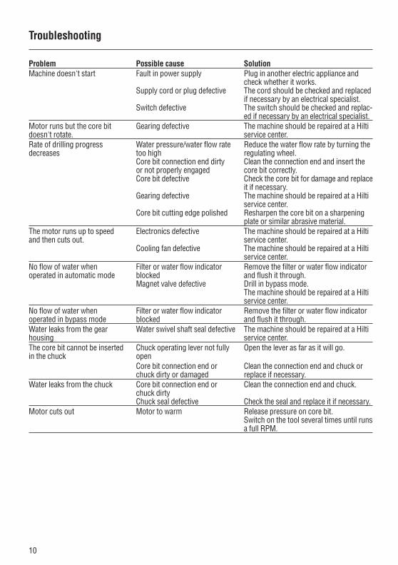
Troubleshooting
Problem Possible cause SolutionMachine doesn't start Fault in power supply Plug in another electric appliance and
check whether it works.Supply cord or plug defective The cord should be checked and replaced
if necessary by an electrical specialist.Switch defective The switch should be checked and replac-
ed if necessary by an electrical specialist.Motor runs but the core bit Gearing defective The machine should be repaired at a Hilti doesn't rotate. service center.Rate of drilling progress Water pressure/water flow rate Reduce the water flow rate by turning thedecreases too high regulating wheel.
Core bit connection end dirty Clean the connection end and insert the or not properly engaged core bit correctly.Core bit defective Check the core bit for damage and replace
it if necessary.Gearing defective The machine should be repaired at a Hilti
service center. Core bit cutting edge polished Resharpen the core bit on a sharpening
plate or similar abrasive material.The motor runs up to speed Electronics defective The machine should be repaired at a Hilti and then cuts out. service center.
Cooling fan defective The machine should be repaired at a Hilti service center.
No flow of water when Filter or water flow indicator Remove the filter or water flow indicator operated in automatic mode blocked and flush it through.
Magnet valve defective Drill in bypass mode. The machine should be repaired at a Hilti service center.
No flow of water when Filter or water flow indicator Remove the filter or water flow indicator operated in bypass mode blocked and flush it through. Water leaks from the gear Water swivel shaft seal defective The machine should be repaired at a Hilti housing service center.The core bit cannot be inserted Chuck operating lever not fully Open the lever as far as it will go.in the chuck open
Core bit connection end or Clean the connection end and chuck or chuck dirty or damaged replace if necessary.
Water leaks from the chuck Core bit connection end or Clean the connection end and chuck.chuck dirtyChuck seal defective Check the seal and replace it if necessary.
Motor cuts out Motor to warm Release pressure on core bit.Switch on the tool several times until runsa full RPM.
1_BA_DDEC_1_P3_en.qxp:1_BA_DDEC_1_P3_en 16.10.2013 10:18 Uhr Seite 10
Printed: 02.12.2013 | Doc-Nr: PUB / 5163253 / 000 / 01

*337335*
3373
35
Hilti CorporationLI-9494 SchaanTel.: +423 / 234 21 11Fax:+423 / 234 29 65www.hilti.com
Hilti = registered trademark of Hilti Corp., Schaan W 2518 | 1013 | 0,6-Pos. 3 | 1 Printed in Liechtenstein © 2013Right of technical and programme changes reserved S. E. & O. 337335 / A3
Printed: 02.12.2013 | Doc-Nr: PUB / 5163253 / 000 / 01