dcmi spec v1 0 with logos 6-27 - intel | data center ... center manageability interface...
TRANSCRIPT

– DCMI –
Data Center Manageability Interface Specification
v1.0
Revision 1.0
Intel Corporation

Data Center Manageability Interface Specification
Version 1.0 2 of 45
THIS SPECIFICATION IS PROVIDED "AS IS" WITH NO WARRANTIES WHATSOEVER, INCLUDING ANY WARRANTY OF MERCHANTABILITY, NONINFRINGEMENT, FITNESS FOR ANY PARTICULAR PURPOSE, OR ANY WARRANTY OTHERWISE ARISING OUT OF ANY PROPOSAL, SPECIFICATION OR SAMPLE. Intel disclaims all liability, including liability for infringement of any proprietary rights, relating to use of information in this specification. No license, express or implied, by estoppels or otherwise, to any intellectual property rights is granted herein, except that a license is hereby granted to copy and reproduce this specification for internal use only. Intel retains the right to make changes to this document at any time, without notice. Intel make no warranty for the use of this document and assume no responsibility for any error which may appear in the document, nor does it make a commitment to update the information contained herein. Designers must not rely on the absence or characteristics of any features or instructions marked "reserved" or "undefined." Intel reserves these for future definition and shall have no responsibility whatsoever for conflicts or incompatibilities arising from future changes to them. Intel is a trademark or registered trademark of Intel Corporation or its subsidiaries in the United States and other countries. † Other names and brands may be claimed as the property of others. Copyright 2007-2008 Intel Corporation. All Rights Reserved.

Data Center Manageability Interface Specification
3 of 45 Version 1.0
Revision History
Date Version Rev Modifications
05/01/2008 1.0 1.0 DCMI v1.0 initial release

Data Center Manageability Interface Specification
Version 1.0 4 of 45
Table of Contents
1. INTRODUCTION ...............................................................................................................................................7
1.1. SCOPE.............................................................................................................................................................7 1.2. AUDIENCE ......................................................................................................................................................8 1.3. DOCUMENT ORGANIZATION ...........................................................................................................................8 1.4. REFERENCE DOCUMENTS ...............................................................................................................................8 1.5. CONVENTIONS AND TERMINOLOGY ................................................................................................................9
2. DCMI OVERVIEW...........................................................................................................................................10
2.1. DATA CENTER SERVER MANAGEMENT ........................................................................................................10 2.2. DCMI RELATIONSHIP TO OTHER MANAGEMENT STANDARDS ......................................................................10 2.3. DATA CENTER MANAGEABILITY REQUIREMENTS.........................................................................................10 2.4. DCMI SPECIFIC COMMANDS AND GROUP CODE ..........................................................................................11 2.5. DCMI 1.0 COVERAGE ..................................................................................................................................11
3. PLATFORM REQUIREMENTS.....................................................................................................................12
3.1. MANDATORY REQUIREMENTS ......................................................................................................................12 3.1.1. Identification........................................................................................................................................12 3.1.2. Chassis Power......................................................................................................................................13 3.1.3. Event Logging......................................................................................................................................13 3.1.4. Temperature Monitor...........................................................................................................................13
3.2. OPTIONAL REQUIREMENTS ...........................................................................................................................14 3.2.1. Power Management .............................................................................................................................14
4. SECURITY REQUIREMENTS .......................................................................................................................15
4.1. PRIVILEGE LEVELS........................................................................................................................................16
5. MANAGEABILITY ACCESS REQUIREMENTS ........................................................................................17
5.1. TYPES OF MANAGEABILITY ACCESS..............................................................................................................17 5.2. GENERAL MANAGEABILITY ACCESS REQUIREMENTS ...................................................................................17 5.3. PHYSICAL INTERFACE REQUIREMENTS .........................................................................................................18
5.3.1. Mandatory Requirements.....................................................................................................................18 5.3.2. Optional Requirements ........................................................................................................................19
5.4. PROTOCOL REQUIREMENTS ..........................................................................................................................20 5.4.1. Mandatory Requirements.....................................................................................................................20 5.4.2. Optional Requirements ........................................................................................................................20
5.5. SERVER MANAGEABILITY DISCOVERY REQUIREMENTS................................................................................21 5.5.1. Recommended Requirements ...............................................................................................................21
5.6. REMOTE CONFIGURATION AND PROVISIONING REQUIREMENTS....................................................................22 5.6.1. Optional Requirements ........................................................................................................................22
6. PLATFORM COMMANDS REQUIREMENTS ...........................................................................................23
6.1. GET DCMI CAPABILITIES INFO COMMAND ..................................................................................................24 6.2. CHASSIS COMMANDS....................................................................................................................................27
6.2.1. Get Chassis Status Command ..............................................................................................................27 6.2.2. Chassis Control Command ..................................................................................................................27 6.2.3. Chassis Identify Command ..................................................................................................................27 6.2.4. Get ACPI Power State Command ........................................................................................................27
6.3. DCMI LOGGING ...........................................................................................................................................28 6.3.1. Get SEL Info Command .......................................................................................................................28 6.3.2. Reserve SEL Command........................................................................................................................28 6.3.3. Get SEL Entry Command.....................................................................................................................29 6.3.4. Clear SEL Command ...........................................................................................................................29
6.4. IDENTIFICATION SUPPORT.............................................................................................................................30 6.4.1. Asset Tag..............................................................................................................................................30 6.4.2. Get Device ID Command.....................................................................................................................31

Data Center Manageability Interface Specification
5 of 45 Version 1.0
6.4.3. Get System GUID Command ...............................................................................................................31 6.5. SENSOR & STORAGE COMMANDS .................................................................................................................32
6.5.1. Data Center Sensors ............................................................................................................................32 6.5.2. Get DCMI Sensor Info Command........................................................................................................32 6.5.3. DCMI specific SDR Information..........................................................................................................32 6.5.4. Get Sensor Reading Command ............................................................................................................33 6.5.5. Usage Model........................................................................................................................................33
6.6. POWER MANAGEMENT .................................................................................................................................34 6.6.1. Get Power Reading..............................................................................................................................34 6.6.2. Get Power Limit...................................................................................................................................35 6.6.3. Set Power Limit....................................................................................................................................35 6.6.4. Activate/Deactivate Power Limit .........................................................................................................36 6.6.5. Sample power management usage scenario ........................................................................................36
7. MANAGEABILITY ACCESS AND SECURITY COMMANDS .................................................................37
7.1. CHANNEL PROVISIONING COMMANDS ..........................................................................................................38 7.1.1. IPMI LAN Interface Configuration......................................................................................................38 7.1.2. IPMI Channel Access Mode ................................................................................................................41
8. GUIDELINES FOR DCMI MANAGEABILITY CONTROLLER..............................................................43
A.1 DCMI COMPLETION CODES...................................................................................................................45

Data Center Manageability Interface Specification
Version 1.0 6 of 45
List of Figures
Figure 3-1 Illustration of Platform Temperature Monitoring.......................................................................................14
List of Tables
Table 1-1, Glossary........................................................................................................................................................9 Table 3-1, Platform Requirements...............................................................................................................................12 Table 4-1, Privilege Levels..........................................................................................................................................16 Table 5-1, Manageability Access.................................................................................................................................17 Table 6-1, Platform Command Definition ...................................................................................................................23 Table 6-2, DCMI Capabilities Command Format........................................................................................................24 Table 6-3, DCMI Capabilities Parameters...................................................................................................................25 Table 6-4, FRU Product Area......................................................................................................................................30 Table 6-5, Get Asset Tag Command............................................................................................................................31 Table 6-6, DCMI Entity ID Extension.........................................................................................................................32 Table 6-7, Get DCMI Sensor Info Command..............................................................................................................32 Table 6-8, Get Power Reading Command ...................................................................................................................34 Table 6-9, Get Power Limit Command........................................................................................................................35 Table 6-10, Set Power Limit Command ......................................................................................................................35 Table 6-11, Activate/Deactivate Power Limit Command ............................................................................................36 Table 7-1, Manageability Access and Security Command List ...................................................................................37 Table 7-2, Set LAN Configuration Parameters Command ..........................................................................................38 Table 7-3, Get LAN Configuration Parameters Command..........................................................................................38 Table 7-4, LAN Configuration Parameters
1.................................................................................................................39
Table 7-5, Set Channel Access Command ...................................................................................................................41 Table 7-6, Get Channel Access Command ..................................................................................................................42 Table A-1, Completion Codes .....................................................................................................................................45

Data Center Manageability Interface Specification
7 of 45 Version 1.0
1. Introduction
This document presents the Data Centers Manageability Interface (DCMI) specifications for
Internet Portal servers. The DCMI specifications define standardized, abstracted interfaces to the
server management subsystem specific to Data Centers Servers. These specifications are built
upon the Intelligent Platform Management Interface (IPMI) 2.0 specification.
The term Data Centers refers to facilities involved in providing internet based services such as
search, mail etc. The unique characteristics of the Internet Portal Data Centers are their huge
infrastructures and very large number of servers that must be managed and maintained. This
opens up new challenges and issues for server manageability.
Traditionally, server system OEMs provide a manageability subsystem that contains a vendor-
specific software stack for platform management that delivers a rich set of IPMI 2.0 features. In
the Internet Portal Data Centers however, only a subset of those features are typically required,
thus fully equipped IPMI 2.0 stack implementations causes unnecessary complexity.
The term “Data Center Server Management” is used to refer to the monitoring and control of
specific functions that are built into the platform hardware and primarily used for monitoring the
health of the system hardware with reliability and uniform behavior across different vendors.
Platform management typically includes monitoring elements such as system temperatures,
power supplies, bus errors etc. Platform management includes automatic and manually driven
recovery capabilities such as local or remote system resets, power on/off operations, logging of
abnormal or ‘out-of-range’ conditions for later examination. Finally, Platform Management
includes inventory information that can help identify a failed hardware unit.
1.1. Scope
This document defines a baseline set of manageability requirements and interfaces for Data
Center Server Management. The specification is targeted to manageability for Internet Portal
servers.
This document uses IPMI 2.0 as its foundation. The specification inherits the IPMI architecture,
common commands, event formats, data records, and capabilities that are appropriate for use in
Data Center Server Management. This includes accessing the Data Center Server Management
functions using IPMI via LAN, Serial, and local interfaces. An implementation may include
IPMI-based features that are not called out or referenced by this specification. The existence and
operation of such capabilities is outside the scope of this document as long as the system
implementation is configurable in a non-volatile manner to operate in conformance with this
specification.
All commands defined in this document comply with the IPMI specification unless otherwise
specified. This specification is not intended to duplicate command sets from the IPMI
Specification. Therefore, in most cases, this document references the IPMI specification for

Data Center Manageability Interface Specification
Version 1.0 8 of 45
command definitions. In some cases, portions of command formats and definitions are duplicated
as necessary to show the usage of the command in the context of the DCMI specification.
1.2. Audience
This document is written for engineers, system integrators and software developers involved in
the designing or interfacing to Data Center Server management hardware. Familiarity with
microcontrollers, software programming, and PC and server architecture is assumed. For basic
and/or supplemental information, refer to the appropriate reference documents.
1.3. Document Organization
Chapters 1 to 2 Provides overview and intent of the specification
Chapters 3 Provides the version map for the specification.
Chapters 4 to 6 Describes the DCMI requirements
Chapters 7 and above Describe the command set implementation for DCMI requirements, this
section requires understanding of IPMI specification.
1.4. Reference Documents
The following documents are companion and supporting specifications for DCMI and associated
interfaces:
[FRU] Platform Management FRU Information Storage Definition v1.0, ©1999 Intel Corporation, Hewlett-
Packard Company†, NEC Corporation†, and Dell Computer Corporation†. Provides the field
definitions and format of Field Replaceable Unit (FRU) information.
http://developer.intel.com/design/servers/ipmi
[I2C] The I
2C Bus And How To Use It, ©1995, Philips Semiconductors†. This document provides the
timing and electrical specifications for I2C busses.
[IPMB] Intelligent Platform Management Bus Communications Protocol Specification v1.0, ©1998 Intel
Corporation, Hewlett-Packard Company, NEC Corporation, and Dell Computer Corporation.
[IPMI] Intelligent Platform Management Interface Specification Revision 2.0.
[DCMI-RR] DCMI Server Management Reliability and Resilience Specification, Revision 0.3.
[RFC 2119] Key words for use in RFCs to Indicate Requirement Levels.

Data Center Manageability Interface Specification
9 of 45 Version 1.0
1.5. Conventions and Terminology
If not explicitly indicated, bits in figures are numbered with the most significant bit on the left
and the least significant bit on the right. Also, unless otherwise indicated byte order, command
notations, and syntax follow the conventions used in [IPMI 2.0].
Refer to [RFC 2119] for terminology definition of shall, must, should and may.
This document uses the following terms and abbreviations:
Table 1-1, Glossary
Term Definition
BMC Baseboard Management Controller.
DHCP Dynamic Host Control Protocol, RFC 2131
DCMI Data Center Management Interface.
IPMI Intelligent Platform Manageability Interface
IPDC Internet Portal Data Centers such as MS-Live†, Amazon†, Yahoo† etc.
Mandatory requirements
Requirements which are considered common across all the IPDC’s. These requirements are designated as Mandatory and must be met for compliance with this specification.
MD5 RSA Data Security, Inc. MD5 Message-Digest Algorithm. An algorithm for forming a 128-bit digital signature for a set of input data. Improved over earlier algorithms such as MD2.
Optional requirements
Requirements, which may be desired by some IPDC’s are designated as Optional in this specification. These requirements are not required to be met for compliance with this specification.
PSU Power Supply Unit. The power supply unit that provides the power rails to the baseboard and peripheral equipments.
Recommended requirements
Requirements which a considered important by some IPDCs, but are not a common requirement across all IPDCs are designated as Recommended in the specification. These requirements are not required to be met for compliance with this specification. However, they may be requirements of some individual IPDCs.
SDR Sensor Data Record. A data record, defined in IPMI, that describes the platform management sensor type, locations, event generation capabilities, and access information to software that accesses the platform management subsystem.
SEL System Event Log. A non-volatile storage area and associated interfaces for storing system platform event information for later retrieval.
SMS System Management Software. Local software that accesses the platform management subsystem. SMS is typically software that is designed to run as an agent or application under the OS.

Data Center Manageability Interface Specification
Version 1.0 10 of 45
2. DCMI Overview
This section presents an overview of DCMI and its main elements and characteristics.
2.1. Data Center Server Management
The term Data Center Server Management refers to autonomous monitoring and recovery
features implemented directly in server management hardware and firmware. The key
characteristic of Intelligent Platform Management is that inventory, monitoring, logging, and
recovery control functions are available independent of the main processors, BIOS, and operating
system. Platform management functions can also be made available when the system is in a
powered down state.
The DCMI specifications seek to define a common subset of the key components of IPMI that is
suited for the Data Center and delivers interoperability across DCMI implementations on
different systems and from different vendors.
2.2. DCMI Relationship to other Management Standards
DCMI is an interface specification that is ‘management software neutral’ providing monitoring
and control functions that could be exposed through standard management software interfaces.
DCMI Specification has a derived relationship to [IPMI], with the goal of only adding or
modifying specific IPMI features or commands when necessary for Data Center applications and
without compromising the integrity of the IPMI specification.
2.3. Data Center Manageability Requirements
In order to capture the requirements driving Data Center manageability from the broader IPMI
Specification, there are specific requirements that are defined. This definition provides the
ability for Data Center server system OEM(s) and users to understand the scope and usage
models of IPMI from Data Center point of view.
The requirements are broadly covered under
1. Platform Functions
2. Security Expectations
3. Manageability Access

Data Center Manageability Interface Specification
11 of 45 Version 1.0
2.4. DCMI Specific Commands and Group Code
All commands that are defined by this specification as extensions to IPMI, are defined under the
IPMI Group Extension Network Function code 2Ch/2Dh REQ 0x2Ch, RSP 0x2Dh.
Per the specification of the IPMI Group Extension Network Function code in [IPMI], the value
DCh is used as the defining body code in the first byte of request and response message (REQ
and RSP) to identify DCMI specific messages. The rest of the document will use DCGRP as the
symbolic reference to the use of the Group Extension Network Function code together with DCh
as the defining the body code.
DCMI Group Code (DCGRP) = DCh
2.5. DCMI 1.0 Coverage
The minimum compliance includes all mandatory requirements to be compliant with DCMI
specification.
1. Mandatory features
a. Reliable Local and Remote Power on/off/reset.
b. IPMI 2.0, Serial Over LAN Console redirection from a remote server.
c. Identification of the server, by device ID and GUID.
d. Provide accurate System Event Logging.
e. Reliable in-band KCS and out-of-band LAN.
f. Monitor temperature characteristics of the server from local and remote console.
2. Recommended features
a. Identification of the server by Asset tags
b. Server manageability discovery. Refer to Section 5.6
3. Optional features
a. Monitor and control platform power consumption.
b. IPMI Terminal Mode (TMODE) support for Serial.
c. Remote management controller provisioning.

Data Center Manageability Interface Specification
Version 1.0 12 of 45
3. Platform Requirements
The platform requirements represent the set of manageability functions, that are required to be
implemented to support DCMI. These functions shall have an ability to respond to all applicable
manageability transports.
Table 3-1, Platform Requirements
Function Function Details
In-band(I)/
Out-of-band(O)
Capability*
Mandatory(M)/
Optional(O)
Identification BMC ID/Version Info System GUID Asset Tag
I, O I, O I, O
M M M
Chassis Power Power On Power Off Power Reset
O I, O I, O
M M M
Event Logging
Get Log in IPMI SEL format Clear Log
I, O I, O
M M
Temperature Monitoring
Inlet Temperature (s) CPU Temperature (s) Baseboard Temperature (s)
I, O I, O I, O
M M
M
Power Management Set Power Limit Get Power Limit Get Power Reading
I, O I, O I, O
O O
O
* Where In-band (I) refers to functions that are accessed locally by software via an IPMI System
(host) interface to BMC, and out-of-band (O) refers to functions that are accessed via a remote
interface to the BMC, such as LAN.
3.1. Mandatory Requirements
3.1.1. Identification
The following lists the basic Identification support requirements for DCMI. See Section 6.4
Identification Support for additional information and requirements.
1. If the server supports identification using IPMI Asset tags, the server shall conform to
FRU 1.1 Specification to define a Asset Tag information to be programmable by OEM
and retrievable by a IPMI command.
2. The platform shall support a system GUID and the Get System GUID command

Data Center Manageability Interface Specification
13 of 45 Version 1.0
3.1.2. Chassis Power
The platform shall provide power on/off/reset control and status using the Chassis Control
command and the Get Chassis Status command per Section 6.2 of [IPMI 2.0]. In addition, the
platform shall support Get ACPI Power State command for System Power State as described in
Section 20.7 of [IPMI 2.0]
Refer to [DCMI-RR] for reliability expectations.
3.1.3. Event Logging
The following lists the basic event logging and log access support requirements for DCMI. See
Section 6.3 for additional information and requirements.
1. The platform shall provide System Event Log (SEL), as specified by [IPMI 2.0 ].
2. Per [IPMI], local or remote software is required to periodically monitor the SEL and clear
it using the Clear SEL command. The platform may also offer automatic SEL rollover,
clearing, or overwriting capabilities. If provided, the platform shall provide a
configuration mechanism to allow capabilities to be disabled.
3.1.4. Temperature Monitor
The DCMI platform Temperature Monitor provides the basic primitives for accessing the server
thermal sensors. This provides a common mechanism for acquiring the platform specific
temperature data and for validating the available thermal data in DCMI conformant platforms.
The following temperatures shall be provided as IPMI Analog Sensors using the 'temperature'
sensor/event type.
Inlet Temperature: Defined as the temperature of the inlet edge of the chassis. This measures
the airflow temperature entering the chassis. There shall be one or more
inlet temperature sensors supplied by the platform.
CPU Temperature: Defined as the temperature of the processor(s). There shall be one or
more temperature sensors provided for each individual processor package.
Ambient Temperature: Defined as the temperatures measured in strategic locations on the server
motherboard to provide temperature mapping across the platform. There
shall be one or more baseboard temperature sensors provided for the
platform.

Data Center Manageability Interface Specification
Version 1.0 14 of 45
Figure 3-1 Illustration of Platform Temperature Monitoring
3.2. Optional Requirements
3.2.1. Power Management
The platform shall provide means to monitor and control server power usage. Refer to Section
6.6, Power Management for additional information and requirements.
The following list of requirements shall be met to conform to DCMI power management:
1. PSU shall provide power monitoring sensors for input power or input current and voltage.
2. Power Monitoring sensors shall be updated at an average rate of at least once per second.
3. Power limiting shall perform corrective action if the power limiting control fails to lower
the power consumption as requested in the form of power cycling options.
4. Power limiting shall provide configuration option for setting the maximum time expected
for power limiting , in multiples of power monitor sampling time.
5. Platform shall provide the power management controller discovery information, if the
power management controller is a satellite controller.
Server
INLET HOT
CPU 1
CPU 2
Ambient
Temp Ambient
INLET INLET
HOT HOT

Data Center Manageability Interface Specification
15 of 45 Version 1.0
4. Security Requirements
This section defines the common support requirements for data integrity, user authentication, and
confidentiality algorithms and configuration options for remote management access with DCMI.
Individual Data Center installations make their choice of which options to use based on their own
security requirements for the site.
The requirement has three primitives
1. Authentication
2. Encryption (confidentiality)
3. Privilege Levels
In general, the combination of authentication and encryption are classified into three modes of
operation
1. Simple Security - no need for securing the environment, like lab or fully secured facility
2. Authentication Only - Used on Secure environments which looks for user audits
3. Authentication and Encryption - Used in general unsecured situations.
Table 4, Mandatory Cipher Suite Support
ID Characteristics Cipher Suite
Authentication
Algorithm
Integrity
Algorithm(s)
Confidentiality
Algorithm(s)
0 “straight password"
00h, 00h, 00h RAKP-none None None
1 S 01h, 00h, 00h None None
2 S, A 01h, 01h, 00h None
3 S, A, E 01h, 01h, 01h
RAKP-HMAC-SHA1 HMAC-SHA1-96
AES-CBC-128
6 S 02h, 00h, 00h None None
7 S, A 02h, 02h, 00h None
8 S, A, E 02h, 02h, 01h
HMAC-MD5-128
AES-CBC-128
11 S, A 02h, 03h, 00h None
12 S, A, E 02h, 03h, 01h
RAKP-HMAC-MD5
MD5-128
AES-CBC-128 Key: S = authenticated session setup (correct role, username and password/key required to establish session) A = authenticated payload data supported. E = authentication and encrypted payload data supported
PLEASE NOTE: Addition of SHA2 algorithms are under consideration by IPMI consortium to
be added to IPMI Specification. Future errata and revisions of DCMI specification will inherit
the SHA2 mechanism when it is available in the IPMI Specification.
Data Center Manageability Interface Specification
Version 1.0 16 of 45
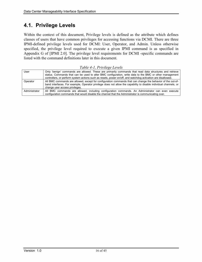
4.1. Privilege Levels
Within the context of this document, Privilege levels is defined as the attribute which defines
classes of users that have common privileges for accessing functions via DCMI. There are three
IPMI-defined privilege levels used for DCMI: User, Operator, and Admin. Unless otherwise
specified, the privilege level required to execute a given IPMI command is as specified in
Appendix G of [IPMI 2.0]. The privilege level requirements for DCMI -specific commands are
listed with the command definitions later in this document.
Table 4-1, Privilege Levels User Only ‘benign’ commands are allowed. These are primarily commands that read data structures and retrieve
status. Commands that can be used to alter BMC configuration, write data to the BMC or other management controllers, or perform system actions such as resets, power on/off, and watchdog activation are disallowed.
Operator All BMC commands are allowed, except for configuration commands that can change the behavior of the out-of-band interfaces. For example, Operator privilege does not allow the capability to disable individual channels, or change user access privileges.
Administrator All BMC commands are allowed, including configuration commands. An Administrator can even execute configuration commands that would disable the channel that the Administrator is communicating over.
Data Center Manageability Interface Specification
17 of 45 Version 1.0
5. Manageability Access Requirements
DCMI requirements for manageability access
1. The manageability access chosen shall be reliable refer to [DCMI-RR].
2. The manageability access chosen works in compliance with IPMI Specifications.
5.1. Types of Manageability access
The manageability access broadly classified based on proximity to management controller
a. In-band, Local OS based app/agent assisted data gathering using management controller
b. Out-of-band, Remote agent assisted data gathering using management controller.
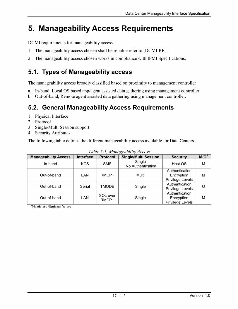
5.2. General Manageability Access Requirements
1. Physical Interface
2. Protocol
3. Single/Multi Session support
4. Security Attributes
The following table defines the different manageability access available for Data Centers.
Table 5-1, Manageability Access Manageability Access Interface Protocol Single/Multi Session Security M/O
1
In-band KCS SMS Single
No Authentication Host OS M
Out-of-band LAN RMCP+ Multi Authentication Encryption
Privilege Levels M
Out-of-band Serial TMODE Single Authentication Privilege Levels
O
Out-of-band LAN SOL over RMCP+
Single Authentication Encryption
Privilege Levels M
1Mandatory /Optional feature

Data Center Manageability Interface Specification
Version 1.0 18 of 45
5.3. Physical Interface Requirements
5.3.1. Mandatory Requirements
5.3.1.1. KCS (Keyboard Control Style) Interface Requirements
The KCS interface is one of the supported BMC to SMS interfaces. The KCS interface is
specified solely for SMS messages. All IPMI commands used for DCMI must be supported over
the KCS interface.
5.3.1.2. LAN Interface Requirements
LAN should be capable of transporting RMCP+ protocol, as defined by IPMI Specification
Section 13 and the following Data Center specific requirements.
1. Gratuitous ARP shall be disabled by default when the platform is shipped or whenever
platform management subsystem firmware is upgraded, unless an alternative configuration is
requested by the Data Center customer.
2. BMC generated ARP control shall be enabled by default when the platform is shipped or
whenever platform management subsystem firmware is upgraded, unless an alternative
configuration is requested by the Data Center customer.
3. IP Address source may be static or use DHCP. It is recommended to configure DHCP with
infinite lease time. (It is assumed that the Data Centers to provide a reliable IP address source
for LAN interface).
4. IPMI Over LAN shall be present in standby power rail.
5. IPMI Channel Access mode shall be set to “Always Available”.
6. BMC shall be resilient to ARP Storm or anticipated network surges
7. BMC shall not be the cause of any ARP poisoning or floating unauthorized IP address in the
form of broadcast or unicast IP packets.
8. Platform shall provide at least one LAN channel as the primary LAN channel, with the
primary LAN channel used for Serial Over LAN (SOL) communication.
9. Platform may provide additional LAN channel and designate as secondary LAN channel.
10. Platform shall support VLAN capability on primary LAN channel and may support VLAN
capability on secondary LAN Channel.
Refer to [DCMI-RR] for reliability expectations.

Data Center Manageability Interface Specification
19 of 45 Version 1.0
5.3.2. Optional Requirements
5.3.2.1. Serial Interface Requirements
Serial interface is optional. If implemented, the interface shall be capable of supporting Direct
connected Terminal Mode as described in [IPMI] and the following Data Center specific
requirements:
1. Shall support Port Sharing between System and BMC, to switch between TMODE and
BIOS/OS.
2. Shall be capable of supporting baud rates from 9.6Kbps to 115.2 Kbps

Data Center Manageability Interface Specification
Version 1.0 20 of 45
5.4. Protocol Requirements
5.4.1. Mandatory Requirements
5.4.1.1. SMS Protocol for In-band Access
As described in [IPMI] Specification Section 10.
5.4.1.2. RMCP+ Protocol for IPMI over LAN Access
As described in [IPMI] Specification Section 13.
5.4.1.3. Serial Over LAN Protocol for LAN Access
As described in [IPMI]. The SOL uses RMCP+ as the transport to communicate with
Manageability controller.
Specific Data Center requirements
1. Shall support a baud rate of 9.6115.2 Kbps.
2. Should support baud rate of 9.6Kbps to 115.2 Kbps
3. Should be reliable with minimal distortion of data.
4. Shall support hardware flow of the serial controller per [IPMI].
5.4.1.4. Session and User Requirements
Sessions and User management should comply with [IPMI] in addition to the following
requirements:
1. Session/User Primitives shall be provided by OEM/Platform.
a. Total number of configurable IPMI users.
b. Total number of supported and active IPMI sessions.
5.4.2. Optional Requirements
5.4.2.1. Terminal MODE (TMODE) Protocol
If implemented, the TMODE protocol shall be implemented as described in [IPMI] with the
following additional requirements.
1. Shall support POWER ON, POWER OFF
2. Shall support BOOT OPTIONS
3. Should support HEX command interface.

Data Center Manageability Interface Specification
21 of 45 Version 1.0
5.5. Server Manageability Discovery Requirements
5.5.1. Recommended Requirements
The DCMI servers may be made as required by IPDC’s to provide discovery mechanisms for
both in-band and out-of-band transports.
5.5.1.1. In-band Discovery Requirements
Systems using in-band discovery mechanisms, such as KCS, should be able to query the
management controller for DCMI discovery data
a. DCMI Version Compliance
b. Asset Tag
c. Mac Address associated with Primary and Secondary LAN Channels.
5.5.1.2. Out-of-band Discovery Requirements
Apart from supporting the in-band discovery messages through out-of-band transports.
DHCP enabled management controllers
The management controllers shall publish itself as a DCMI controller when using DHCP
DISCOVER mechanisms by setting option 12 Host Name of DHCP Discover packet to have the
host name indicate “DCMI”. The management controller shall provide discovery mechanism
using DCMI Get Capabilities Info command to identify the availability of this requirement in the
platform.
Non-DHCP enabled management controllers using Static IP address assignment
Gratuitous ARP can be used for discovery process by matching MAC address.

Data Center Manageability Interface Specification
Version 1.0 22 of 45
5.6. Remote Configuration and Provisioning Requirements
5.6.1. Optional Requirements
Due to the number of servers to configure for manageability access in the Data Center, the
manageability controller may provide an ability for remote provisioning of the baseboard
management controller, which includes manageability controller firmware updates and user
configuration.
The requirement is a capability OEM can provide to IPDC’s and the DCMI specification does
not in any way standardizes the implementation model.
A suggested model using the IPMI 2.0.
1. The manageability controller may provide an ability for a secure RMCP+ connection for out-
of-band configuration.
2. The manageability controller may provide an ability to enable/disable out-of-band
manageability controller configuration.
3. The manageability controller may provide a pre-configuration user name/password/key.
4. The manageability controller may provide a pre-configuration Cipher Suite using MAC
address to derive the key.
5. The manageability controller may provide an ability to disable the pre-configuration use
name/password.

Data Center Manageability Interface Specification
23 of 45 Version 1.0
6. Platform Commands Requirements
The platform functional commands shall be provide by all Data Center platforms conforming to
Data Center IPMI specification.
Table 6-1, Platform Command Definition NetFn CMD M/O
1 Min Privilege Level
Discovery Command
Get DCMI Capability Info DCGRP (2Ch) 01h M User
Chassis Commands
Get Chassis Status Chassis (00h) 01h M User
Chassis Control Chassis (00h) 02h M Admin
Chassis Identify Chassis (00h) 04h M Operator
Get ACPI Power State App (06h) 07h M User
Logging Commands
Get SEL Info Storage (0Ah) 40h M Operator
Reserve SEL Storage (0Ah) 42h M Operator
Get SEL Entry Storage (0Ah) 43h M Operator
Clear SEL Storage (0Ah) 47h M Operator
IPM Device “Global” Commands
Get Asset Tag DCGRP (2Ch) 06h M User
Get Device ID App (06h) 01h M User
Get System GUID App (06h) 37h M User
Sensor & Storage Commands
Get DCMI Sensor Info DCGRP (2Ch) 07h M Operator
Get SDR Storage (0Ah) 23h M Operator
Get Sensor Reading S/E (04h) 2Dh M Operator
Power Management
Get Power Reading DCGRP (2Ch) 02h O Admin
Get Power Limit DCGRP (2Ch) 03h O Admin
Set Power Limit DCGRP (2Ch) 04h O Admin
Activate/Deactivate Power Limit DCGRP (2Ch) 05h O Admin
App = Application Network Function Code S/E = Sensor/Event Network Function Code DCGRP = DCMI Group Extension Network Function Code 1 Mandatory or Optional Features

Data Center Manageability Interface Specification
Version 1.0 24 of 45
6.1. Get DCMI Capabilities Info Command
The function is responsible for providing the available capabilities of the platform specific to
Data Center. The command is session-less and can be called similar to the Get Authentication
Capability command. This command is a bare-metal provisioning command, and the availability
of features does not imply the features are configured.
Table 6-2, DCMI Capabilities Command Format Byte data field
Request Data 1 Group Extension Identification = DCh
2 Parameter Selector
Response Data 1 Completion Code. Refer to Section A.1 - DCMI Completion Codes.
2 Group Extension Identification = DCh
3:4 DCMI Specification Conformance
Byte 1 - Major Version
Byte 2 - Minor Version
5 Parameter Revision = 01h
6: N Parameter data, per Table 6-3, DCMI Capabilities Parameters

Data Center Manageability Interface Specification
25 of 45 Version 1.0
Table 6-3, DCMI Capabilities Parameters Parameter # Parameter Data (non-volatile unless otherwise noted)
Supported DCMI Capabilities 1
This field returns the supported capabilities available in the server in
conformance to DCMI specification for both Platform and Manageability
access.
All reserved bits shall be set to 0b
byte 1 Mandatory Platform capabilities
All bits: 0b = Not Compliant with DCMI Specification
1b = Compliant with DCMI Specification
[7-3] Reserved
[3] Temperature Monitor
[2] Chassis Power
[1] SEL logging
[0] Identification Support
byte 2 Optional Platform capabilities
All bits: 0b = Not Compliant with DCMI Specification
1b = Compliant with DCMI Specification
[7-1] Reserved
[0] Power Management
byte 3 Manageability Access Capabilities
All bits: 0b = Not present
1b = Available
[7-6] Reserved
[5] VLAN Capable
[4] SOL Supported
[3] Out-Of-Band Primary LAN Channel Available
[2] Out-Of-Band Secondary LAN Channel Available. (Optional)
[1] Out-Of-B Serial TMODE Available (Optional)
[0] In-band KCS Channel Available
Mandatory Platform Attributes 2 This field returns the platform attributes required for the platform capabilities.
All reserved bits shall be set to 0b
byte 1:2 SEL Attributes (Mandatory)
[15] SEL automatic rollover enabled (SEL Overwrite)
0b = Not present
1b = Available
[14-12] Reserved (0b)
[11-0] Number of SEL entries (Maximum 4096)
byte 3 Identification Attributes (Mandatory)
All bits: 0b = Not present
1b = Available
[7-3] Reserved
[2] Asset Tag Support (Recommended)
[1] DHCP Host Name Support (Recommended)
[0] GUID Support (Mandatory)
byte 4 Temperature Monitoring
All bits: 0b = Not present
1b = At least 1 present
[7-4] Reserved
[2] Baseboard temperature
[1] Processors temperature
[0] Inlet temperature
[Note: The DCMI Get Sensor Command should be used for discovering the number of the individual temperature sensors]

Data Center Manageability Interface Specification
Version 1.0 26 of 45
Optional Platform Attributes 3 This field returns the attributes required for the recommended platform capabilities
byte 1 Power Management Device Slave Address
[7:1] - 7-bit I2C† Slave Address
of device on IPMB.
[0] - reserved. Write as 0b
[20h = BMC , XXh = Satellite/External controller ]
byte 2 Power Management Controller Channel Number
[7:4] - Channel Number for channel that management controller is located on. Use 0h for the primary BMC.
[3:0] - Device Revision
Manageability Access Attributes
4
This field returns the attributes of the manageability access.
byte 1 Mandatory Primary LAN OOB Support (RMCP+ Support Only)
[7-0] Channel Number (0xFFh == Not supported)
byte 2 Optional Secondary LAN OOB Support (RMCP+ Support Only)
[7-0] Channel Number (0xFFh == Not supported)
byte 3 Optional Serial Out-Of-Band TMODE Capability
[7-0] Channel Number (0xFFh == Not Supported)

Data Center Manageability Interface Specification
27 of 45 Version 1.0
6.2. Chassis Commands
Chassis commands perform the following functions
1. Power Status
2. Power On/off/hard reset
3. Identify
6.2.1. Get Chassis Status Command
The following command returns information regarding the high-level status of the system chassis
and main power subsystem.
Refer to [IPMI 2.0] Section 29.2 for command format.
6.2.2. Chassis Control Command
The following command provides a mechanism for providing power up, power down, and reset
control.
Refer to [IPMI 2.0] Section 29.3 for command format.
6.2.3. Chassis Identify Command
This command causes the chassis to physically identify itself by a mechanism chosen by the
system implementation; such as turning on blinking user-visible lights or emitting beeps via a
speaker, LCD panel, etc. Unless the optional “Force Identify On” capability is supported and
used, the Chassis Identify command automatically times out and de-asserts the indication after a
configurable time-out. Software shall periodically resend the command to keep the identify
condition asserted. This will restart the timeout.
Refer to [IPMI 2.0] Section 28.5 for command format.
6.2.4. Get ACPI Power State Command
The command can also be used to retrieve the present power state information that has been set
into the controller. This is an independent setting from the system power state that may not
necessarily match the actual power state of the system. Unspecified bits and codes are reserved
and shall be returned as 0.
Refer to [IPMI 2.0] Section 20.7 for command format.

Data Center Manageability Interface Specification
Version 1.0 28 of 45
6.3. DCMI Logging
The System Event Log is a non-volatile repository for system events and certain system
configuration information. The device that fields the commands to access the SEL is referred to
as the System Event Log Device or SEL Device.
System Event Logging (SEL) provides the necessary logging for DCMI. SEL can be uploaded,
cleared by the in-band and out-of-band agents using the defined IPMI commands.
OEM’s can offer automatic rollover or overwrite capability to enhance the robustness of the SEL
logging. The capabilities shall be advertised as part of the Capabilities command. It is
recommended that overwrite mechanism should purge out entire SEL before adding new entries.
To decode the SEL entry
1. Sensor Type Codes (Refer to IPMI 2.0 Specification Section 42.2)
2. Sensor Number derived from reading SDRs.
6.3.1. Get SEL Info Command
This command returns the number of entries in the SEL, SEL command version, and the
timestamp for the most recent entry and delete/clear. The timestamp format is provided in IPMI
Specification. The Most Recent Addition timestamp field returns the timestamp for the last add or
log operation, while the Most Recent Erase field returns the timestamp for the last delete or clear
operation. This command can also be used to determine if the SEL log is full by checking the
operation support MSB. This will definitively determine if the application should save, then
clear the SEL log.
The Discovery & Capabilities command provides the maximum supported SEL entries.
Refer to [IPMI 2.0] Section 31.2 for command format.
6.3.2. Reserve SEL Command
This command is used to set the present ‘owner’ of the SEL, as identified by the Software ID or
by the Requester’s Slave Address from the command. The reservation process provides a limited
amount of protection on repository access from the IPMB when records are being deleted or
incrementally read.
Refer to [IPMI 2.0] Section 31.4 for command format.

Data Center Manageability Interface Specification
29 of 45 Version 1.0
6.3.3. Get SEL Entry Command
This command is used to retrieve entries from the SEL. The record data field in the response
returns the 16 bytes of data from the SEL Event Record.
Refer to [IPMI 2.0] Section 31.5 for command format.
6.3.4. Clear SEL Command
The command ‘erases’ all contents of the System Event Log. Since this process may take several
seconds, based on the type of storage device, the command also provides a means for obtaining
the status of the erasure.
Refer to [IPMI 2.0] Section 31.9 for command format.

Data Center Manageability Interface Specification
Version 1.0 30 of 45
6.4. Identification Support
6.4.1. Asset Tag
The platform shall provide an ability for the DCMI customers to add an asset tag unique to each
server by OEM and query it later. The asset tag can be populated by the OEM to the FRU as part
of Product Info. The manageability controller records the asset tag and can be retrieved by using
Get Asset Tag command.
Table 6-4, FRU Product Area Field length
Field
1 Product Area Format Version 7:4 - reserved, write as 0000b 3:0 - format version number = 1h for IPMI FRU specification
1 Product Area Length (in multiples of 8 bytes)
1 Language Code (See section 15)
1 Manufacturer Name type/length byte
N Manufacturer Name bytes
1 Product Name type/length byte
M Product Name bytes
1 Product Part/Model Number type/length byte
O Product Part/Model Number bytes
1 Product Version type/length byte
R Product Version bytes
1 Product Serial Number type/length byte*
P Product Serial Number bytes*
1 Asset Tag type/length byte (Maximum 64 bytes)
Q Asset Tag
1 FRU File ID type/length byte
R FRU File ID bytes. The FRU File version field is a pre-defined field provided as a manufacturing aid for verifying the file that was used during manufacture or field update to load the FRU information. The content is manufacturer-specific. This field is also provided in the Board Info area. Either or both fields may be ‘null’
xx Custom product info area fields, if any (must be preceded with type/length byte)
1 C1h (type/length byte encoded to indicate no more info fields)
Y 00h - any remaining unused space
1 Product Info Area Checksum (zero checksum)
* These fields are always encoded as if the Language Code were English. I.e. if the type/length code bits
7:6=11b the serial number will always be interpreted as ASCII+Latin 1, not UNICODE.

Data Center Manageability Interface Specification
31 of 45 Version 1.0
6.4.1.1. Get Asset Tag Command
This command is supported only if Discovery & Capabilities command indicate Asset tag
support.
Table 6-5, Get Asset Tag Command byte data field
Request Data 1 Group Extension Identification = DCh
2 Offset to read
3 Number of bytes to read (16 bytes maximum)
Response Data 1 Completion Code. Refer to Section A.1 - DCMI Completion Codes.
2 Group Extension Identification = DCh
3 Total Asset Tag Length specified in FRU Data, as specified in Table 6-4, FRU Product Area
4 - N Data
6.4.2. Get Device ID Command
This command is used to retrieve the Intelligent Device’s Firmware/Software Revision, and
Sensor and Event Interface Command specification revision information. The command also
returns information regarding the additional ‘logical device’ functionality (beyond ‘Application’
and ‘IPM’ device functionality) that is provided within the intelligent device, if any.
Refer to [IPMI 2.0] Section 20.1 for command format.
6.4.3. Get System GUID Command
This command provides a Globally Unique ID for the managed system to support the remote
discovery process and other operations. The GUID is typically permanently assigned to a system.
Refer to [IPMI 2.0] Section 22.14 for command format.

Data Center Manageability Interface Specification
Version 1.0 32 of 45
6.5. Sensor & Storage Commands
The sensor management covers the specific sensors for Data Centers and sensor command sets.
6.5.1. Data Center Sensors
1. Inlet Temperature (0 or more Sensors)
2. CPU Temperature ( based on # of processors or cores)
3. Baseboard temperature ( 0 or more Sensors )
The discovery commands for the DCMI Sensors is provided in Get DCMI Sensor section.
6.5.2. Get DCMI Sensor Info Command
Table 6-6, DCMI Entity ID Extension
Entity ID description Entity ID Entity Instance Sensor Type
Inlet Temperature 0x40 0x01…n Temp (01h)
CPU Temperature ( based on # of processors or cores )
0x41 0x01…n Temp (01h)
Baseboard temperature 0x42 0x01…n Temp (01h)
Table 6-7, Get DCMI Sensor Info Command Byte data field
Request Data 1 Group Extension Identification = DCh
2 Sensor Type Refer to Table 6-6, DCMI Entity ID Extension
3 Entity ID Refer to Table 6-6, DCMI Entity ID Extension
4 Entity Instance
00h Retrieve information about all instances associated with Entity ID
01h - FFh – Retrieve only the information about particular instance.
5 Entity Instance Start, Used with Entity Instance 00h for # of instance
exceeding one IPMI Response.
Response Data 1 Completion Code. Refer to Section A.1 - DCMI Completion Codes.
2 Group Extension Identification = DCh
3 Total number of available instances for the Entity ID
4 Number of Record IDs in this response (Max 8 per response)
01h for Entity Instance not equal to 00h
5:6 + N SDR Record ID corresponding to the Entity IDs
1st byte: Record ID LS Byte, used for retrieving SDR records
2nd byte: Record ID MS Byte, used for retrieving SDR records
6.5.3. DCMI specific SDR Information
Most of the DCMI sensors fall under IPMI Sensor Type 01h/02h, [IPMI 2.0] provides the Sensor
Data Record Format for each of the Sensor Types retrievable by Get SDR IPMI Command (Refer

Data Center Manageability Interface Specification
33 of 45 Version 1.0
to [IPMI 2.0] Section 33.12 for command format). The Sensor Data Record information is
essential to convert the raw Sensor reading into units that the platform vendor or system
integrator selected as being appropriate for the device. The table highlights only the fields
specific to conversions factors, please refer to IPMI 2.0 Specification for more specific sensor
details.
6.5.4. Get Sensor Reading Command
This command returns the present reading for sensor. The sensor device may return a stored
version of a periodically updated reading, or the sensor device may scan to obtain the reading
after receiving the request.
Refer to [IPMI 2.0] Section 35.14 for command format.
6.5.5. Usage Model
An reference usage model for querying the Inlet temperature is provided below using the above
commands.
1. Send Get DCMI Sensor Info Command for Inlet Temp, Entity ID = 0x40, Entity Instance
= 0x01
2. Receives the Record ID for the Inlet Temp.
3. Request SDR Info based on Record ID for obtaining the Sensor # and for data calculation.
4. Request Get Sensor Reading IPMI Command with acquired Sensor #.

Data Center Manageability Interface Specification
Version 1.0 34 of 45
6.6. Power Management
Total input platform power monitoring and control is an integral part of DCMI expectations, the
specification standardizes the command sets for discovery, monitoring and control of the server
power. This section is expected to evolve with expanded power management capabilities
Power management feature can be provided by BMC or by an external or satellite controller to
BMC.
Management applications should discover the residency of power management feature as
described in the following commands
Following commands are not supported if Get DCMI Capabilities Info command indicate no
Power management support.
6.6.1. Get Power Reading
Table 6-8, Get Power Reading Command byte data field
Request Data 1 Group Extension Identification = DCh
2 Mode
01h – Power Statistics
3:4 Reserved for future, use 0000h
Response Data 1 Completion Code. Refer to Section A.1 - DCMI Completion Codes.
2 Group Extension Identification = DCh
3:4 Current Power in watts
5:6 Minimum Power over sampling duration in watts
7:8 Maximum Power over sampling duration in watts
9:10 Average Power over sampling duration in watts
11:14 IPMI Specification based Time Stamp
15:18 Statistics reporting time period
Timeframe in milliseconds, over which the controller collects statistics
19 Power Reading State
[0:5] Reserved
[6] 1b – Power Measurement active
0b – No Power Measurement is available.
[7] Reserved

Data Center Manageability Interface Specification
35 of 45 Version 1.0
6.6.2. Get Power Limit
Table 6-9, Get Power Limit Command byte data field
Request Data 1 Group Extension Identification = DCh
2:3 Reserved for future use, use 0000h
Response Data 1 Completion Code. Refer to Section A.1 - DCMI Completion Codes. 00h = Power Limit Active 80h = No Set Power Limit
2 Group Extension Identification = DCh
3:4 Reserved for future use
5 Exception Actions, taken if the Power Limit exceeded and cannot be controlled within the Correction time limit
01h Hard Power Off system
02h – 10h OEM defined actions
6:7 Power Limit Requested in Watts
8:11 Correction time limit in milliseconds
Maximum time taken to limit the power, otherwise exception action will be taken as configured
12:13 Reserved for future use
14:15 Management application Statistics Sampling period in seconds
6.6.3. Set Power Limit
The power limit command sets the power limit parameters on the system. It is recommended to
do a Get Power Limit or check the Get Power Reading command before attempting to set power
limit.
It should be noted that in the current context, this command shall be used to set upper limit of
system power usage and not used as a command interface for dynamic or frequently changing
power limit. The power limit set should be persistent across AC and DC cycles.
Table 6-10, Set Power Limit Command byte data field
Request Data 1 Group Extension Identification = DCh
2:4 Reserved for future use
5 Exception Actions, taken if the Power Limit exceeded and cannot be controlled within the Correction time limit
01h Hard Power Off system
02h – 10h OEM defined actions
6:7 Power Limit Requested in Watts
8:11 Correction time limit in milliseconds
Maximum time taken to limit the power, otherwise exception action will be taken as configured
12:13 Reserved for future use
14:15 Management application Statistics Sampling period in seconds
Response Data 1 Completion Code. Refer to Section A.1 - DCMI Completion Codes.
=00h – Success =84h – Power Limit out of range =85h – Correction Time out of range =89h – Statistics Reporting Period out of range
2 Group Extension Identification = DCh

Data Center Manageability Interface Specification
Version 1.0 36 of 45
6.6.4. Activate/Deactivate Power Limit
The command is used to activate or deactivate the power limit set. This command should
succeed a successful Set Power limit command.
Table 6-11, Activate/Deactivate Power Limit Command byte data field
Request Data 1 Group Extension Identification = DCh
2 Power Limit Activation
00h – Deactivate Power Limit
01h – Activate Power Limit
3:4 Reserved
Response Data 1 Completion Code. Refer to Section A.1 - DCMI Completion Codes.
2 Group Extension Identification = DCh
6.6.5. Sample power management usage scenario
Power monitoring & Control
1. Get Power Reading
2. Get Power Limit
3. If Power Limit is Active
a. Deactivate Power Limit
4. Set Power Limit
5. Activate Power Limit

Data Center Manageability Interface Specification
37 of 45 Version 1.0
7. Manageability Access and Security Commands
This chapter includes all relevant IPMI manageability access and security command sets. These
commands provide the means to use the command sets to establish the requested session and
appropriate security. Unless otherwise specified, all commands are inherited from [IPMI 2.0].
IPMI commands, which requires specific DCMI settings are described in this section, for all
other listed IPMI commands, please refer to [IPMI 2.0].
Table 7-1, Manageability Access and Security Command List
1 Provisioning (P), Runtime (R), Both (A) 2 Mandatory Features (M), Optional Features (O) 3 Used to find the Number of Users
NetFn CMD P/R/Both1 M/O
2
Provision Commands
Set LAN Configuration Parameters Transport 01h P M
Get LAN Configuration Parameters Transport 02h A M
Set Channel Access App 40h P M
Get Channel Access App 41h A M
Set User Access App 43h P M
Get User Access3 App 44h A M
Set User Name App 45h P M
Get User Name App 46h A M
Set User Password App 47h P M
Set User Payload Access App 4Ch P M
Get User Payload Access App 4Dh P M
Set SOL Configuration Parameters Transport 21h P M
Get SOL Configuration Parameters Transport 22h P M
Set Session Privilege Level App 3Bh P M
Runtime Commands
Activate Payload App 48h R M
Deactivate Payload App 49h R M
SOL Activating Transport 20h R M
Get Channel Authentication Capabilities App 38h R M
Get Channel Info App 42h A M
Get Channel Cipher Suites App 54h A M
Get Session Challenge App 39h R M
Activate Session App 3Ah R M
Close Session App 3Ch R M
Get Session Info App 3Dh R M
Serial Support Extension
Set Serial Configuration Transport 10h P O
Get Serial Configuration Transport 11h A O
Set Serial Mux Transport 12h A O
Set Serial Routing Mux Transport 1Ch A O

Data Center Manageability Interface Specification
Version 1.0 38 of 45
7.1. Channel Provisioning Commands
The following commands will be useful to provision the manageability controller with
manageability access and security requirements. The following sections describe some of these
commands in detail with recommended DCMI values for each of the parameters.
7.1.1. IPMI LAN Interface Configuration
Table 7-2, Set LAN Configuration Parameters Command byte data field
Request Data 1 [7:4] - reserved
[3:0] - Channel number.
2 Parameter selector
3:N Configuration parameter data, per Configuration Parameters
Response Data 1 Completion Code. Refer to Section A.1 - DCMI Completion Codes.
80h = parameter not supported.
81h = attempt to set the ‘set in progress’ value (in parameter #0) when not in the ‘set complete’ state. (This completion code provides a way to recognize that another party has already ‘claimed’ the parameters)
82h = attempt to write read-only parameter
Table 7-3, Get LAN Configuration Parameters Command byte data field
Request Data 1 [7] - 0b = get parameter
1b = get parameter revision only.
[6:4] - reserved
[3:0] - Channel number.
2 Parameter selector
3 Set Selector. Selects a given set of parameters under a given Parameter selector value. 00h if parameter doesn’t use a Set Selector.
4 Block Selector (00h if parameter does not require a block number)
Response Data 1 Completion Code. Refer to Section A.1 - DCMI Completion Codes.
Generic codes, plus following command-specific completion code(s):
80h = parameter not supported.
2 [7:0] - Parameter revision.
Format: MSN = present revision. LSN = oldest revision parameter is
backward compatible with. 11h for parameters in this specification.
The following data bytes are not returned when the ‘get parameter revision only’ bit is 1b.
3:N Configuration parameter data, per Table 7-4, LAN Configuration Parameters
If the rollback feature is implemented, the BMC makes a copy of the existing parameters when the ‘set in progress’ state becomes asserted (See the Set In Progress parameter #0). While the ‘set in progress’ state is active, the BMC will return data from this copy of the parameters, plus any uncommitted changes that were made to the data. Otherwise, the BMC returns parameter data from non-volatile storage.

Data Center Manageability Interface Specification
39 of 45 Version 1.0
Table 7-4, LAN Configuration Parameters1
Parameter # DCMI
Value
Parameter Data (non-volatile unless otherwise noted)
Authentication Type Support (Read Only)
1 04h This ‘read only’ field returns which possible Authentication Types (algorithms) can be enabled for the given channel. The following Authentication Type Enables parameter selects which Authentication Types are available when activating a session for a particular maximum privilege level.
[7:6] - reserved
[5:0] - Authentication type(s) enabled for this channel (bitfield):
All bits: 1b = supported
0b = authentication type not available for use.
[5] - OEM proprietary (per OEM identified by the IANA OEM ID in the RMCP Ping Response)
[4] - straight password / key
[3] - reserved
[2] - MD5
[1] - MD2
[0] - none
Authentication Type Enables
2 B1=04h
B2=04h
B3=04h
B4=04h
B5=04h
This field is used to configure which Authentication Types are available for use when a remote console activates an IPMI messaging connection to the BMC for a given requested maximum privilege level. Once the session has been activated, the accepted authentication type will be the only one used for authenticated packets, regardless of the present operating privilege level, or the privilege level associated with the command.
Depending on configuration of per-message and user-level authentication disables, unauthenticated packets (authentication type = none) may also be accepted. The BMC makes no attempt to check or ensure that stricter authentication types are associated with higher requested maximum privilege levels. E.g. it is possible to configure the BMC so activating a session with a maximum privilege level of ‘User’ requires MD5 while ‘Admin’ requires ‘none’.
Note: An implementation that has fixed privilege and authentication type assignments, in which case this parameter can be implemented as Read Only. It is recommended that an implementation that implements a subset of the possible authentication types returns a CCh error completion code if an attempt is made to select an unsupported authentication type.
byte 1: Authentication Types returned for maximum requested privilege = Callback level.
[7:6] - reserved
[5:0] - Authentication type(s) enabled for this channel (bitfield):
All bits: 1b = authentication type enabled for use at given privilege level
0b = authentication type not available for use at given privilege level.
[5] - OEM proprietary (per OEM identified by the IANA OEM ID in the RMCP Ping Response)
[4] - straight password / key
[3] - reserved
[2] - MD5
[1] - MD2
[0] - none
byte 2: Authentication Type(s) for maximum privilege = User level
(format follows byte 1)
byte 3: Authentication Type (s) for maximum privilege = Operator level
(format follows byte 1)
byte 4: Authentication Type (s) for maximum privilege = Administrator level
(format follows byte 1)
byte 5: Authentication Type (s) for maximum privilege = OEM level
(format follows byte 1)
IP Address 3 Should not set
data 1:4 - IP Address
MS-byte first.

Data Center Manageability Interface Specification
Version 1.0 40 of 45
Parameter # DCMI
Value
Parameter Data (non-volatile unless otherwise noted)
IP Address Source 4 02h data 1
[7:4] - reserved
[3:0] - address source
0h = unspecified
1h = static address (manually configured)
2h = address obtained by BMC running DHCP
3h = address loaded by BIOS or system software
4h = address obtained by BMC running other address assignment protocol
MAC Address 5 Should not set
data 1:6 - MAC Address for messages transmitted from BMC.
MS-byte first.
Subnet Mask 6 User Specified
data 1:4 - Subnet Mask. MS-byte first.
BMC-generated ARP control (optional
[2])
10 02h data 1 - BMC-generated ARP control. Note: the individual capabilities for BMC-generated ARP responses and BMC-generated Gratuitous ARPs are individually optional. The BMC should return an error completion code if an attempt is made to enable an unsupported capability.
[7:2] - reserved
[1] - 1b = enable BMC-generated ARP responses
0b = disable BMC-generated ARP responses
[0] - 1b = enable BMC-generated Gratuitous ARPs
0b = disable BMC-generated Gratuitous ARPs
802.1q VLAN ID (12-bit)
20 User Specified
data 1
[7:0] - Least significant 8-bits of the VLAN ID. 00h if VLAN ID not used.
data 2
[7] - VLAN ID enable.
0b = disabled, 1b = enabled. If enabled, the BMC will only accept packets for this channel if they have 802.1q fields and their VLAN ID matches the VLAN ID value given in this parameter.
[6:4] - reserved
[3:0] - most significant four bits of the VLAN ID
802.1q VLAN Priority 21 User Specified
data 1
[7:5] - reserved
[2:0] - Value for Priority field of 802.1q fields. Ignored when VLAN ID enable is 0b (disabled) - See 802.1q VLAN ID parameter, above. Setting is network dependent. By default, this should be set to 000b.
1 Only relevant DCMI fields are provided.

Data Center Manageability Interface Specification
41 of 45 Version 1.0
7.1.2. IPMI Channel Access Mode
This command should be called for volatile and non-volatile settings separately.
Table 7-5, Set Channel Access Command byte DCMI
Values
data field
Request Data
1 01-03h [7:4] - reserved
[3:0] - Channel number (Based on Channel Assignment)
2 42h/82h [7:6] - 00b = don’t set or change Channel Access
01b = set non-volatile Channel Access according to bits [5:0]
10b = set volatile (active) setting of Channel Access according to bits [5:0]
11b = reserved
[5] - PEF Alerting Enable/Disable 0b = enable PEF Alerting 1b = disable PEF Alerting on this channel (the Alert Immediate
command can still be used to generate alerts)
[4] - 0b = enable Per-message Authentication
1b = disable Per-message Authentication. [Authentication required to activate any session on this channel, but authentication not used on subsequent packets for the session.]
[3] - User Level Authentication Enable/Disable.
0b = enable User Level Authentication. All User Level commands are to be authenticated per the Authentication Type that was negotiated when the session was activated.
1b = disable User Level Authentication. Allow User Level commands to be executed without being authenticated.
[2:0] - Access Mode for IPMI messaging
000b = disabled
channel disabled for IPMI messaging
001b = pre-boot only channel only available when system is in a powered down state or in BIOS prior to start of boot.
010b = always available
channel always available for communication regardless of system mode. BIOS typically dedicates the serial connection to the BMC.
011b = shared
same as always available, but BIOS typically leaves the serial port available for software use.
3 4Xh/8Xh
[X= Desired
Privilege Level]
Channel Privilege Level Limit. This value sets the maximum privilege level that can be accepted on the specified channel.
[7:6] - 00b = don’t set or change channel Privilege Level Limit
01b = set non-volatile Privilege Level Limit according to bits [3:0]
10b = set volatile setting of Privilege Level Limit according to bits [3:0] 11b = reserved
[5:4] - reserved
[3:0] - Channel Privilege Level Limit
0h = reserved
2h = USER level
3h = OPERATOR level
4h = ADMINISTRATOR level
5h = OEM Proprietary level
Response Data
1 Completion Code. Refer to Section A.1 - DCMI Completion Codes,
generic, plus following command-specific completion codes:
82h = set not supported on selected channel (e.g. channel is session-less.)
83h = access mode not supported

Data Center Manageability Interface Specification
Version 1.0 42 of 45
Table 7-6, Get Channel Access Command byte data field
Request Data 1 [7:4] - reserved
[3:0] - Channel number.
2 [7:6] - 00b = reserved
01b = get non-volatile Channel Access
10b = get present volatile (active) setting of Channel Access
11b = reserved
[5:0] - reserved
Response Data 1 Completion Code. Refer to Section A.1 - DCMI Completion Codes.
generic, plus following command-specific completion codes:
82h = Command not supported for selected channel (e.g. channel is session-less.)
2 [7:6] - reserved
[5] - 0b = Alerting enabled
1b = Alerting disabled
[4] - 0b = per message authentication enabled
1b = per message authentication disabled
[3] - User Level Authentication Enable
0b = User Level Authentication enabled.
1b = User Level Authentication disabled.
[2:0] - Access Mode
0h = disabled
channel disabled for communication
1h = pre-boot only channel only available when system is in a powered down state or in BIOS prior to start of boot.
2h = always available
channel always available for communication regardless of system mode. BIOS typically dedicates the serial connection to the BMC.
3h = shared
same as always available, but BIOS typically leaves the serial port available for software use.
3 Channel Privilege Level Limit. This value returns the maximum privilege level that can be accepted on the specified channel.
[7:4] - reserved
[3:0] - Channel Privilege Level Limit
0h = reserved
1h = CALLBACK level
2h = USER level
3h = OPERATOR level
4h = ADMINISTRATOR level
5h = OEM Proprietary level

Data Center Manageability Interface Specification
43 of 45 Version 1.0
8. Guidelines for DCMI Manageability Controller
1. Manageability controller shall be resilient and tolerant to abnormal traffic behavior of the
LAN interface, such as Denial of Service (DOS) attacks or other anomalies leading to
controller hang.
2. Manageability controller can provide watch dog timer model, to restart the BMC when it
gets to hang situation.

Data Center Manageability Interface Specification
Version 1.0 44 of 45

Data Center Manageability Interface Specification
45 of 45 Version 1.0
A.1 DCMI Completion Codes
Table A-1, Completion Codes Code Definition
GENERIC COMPLETION CODES 00h, C0h-FFh
00h Command Completed Normally.
C0h Node Busy. Command could not be processed because command processing resources are temporarily unavailable.
C1h Invalid Command. Used to indicate an unrecognized or unsupported command.
C2h Command invalid for given LUN.
C3h Timeout while processing command. Response unavailable.
C4h Out of space. Command could not be completed because of a lack of storage space required to execute the given command operation.
C5h Reservation Canceled or Invalid Reservation ID.
C6h Request data truncated.
C7h Request data length invalid.
C8h Request data field length limit exceeded.
C9h Parameter out of range. One or more parameters in the data field of the Request are out of range. This is different from ‘Invalid data field’ (CCh) code in that it indicates that the erroneous field(s) has a contiguous range of possible values.
CAh Cannot return number of requested data bytes.
CBh Requested Sensor, data, or record not present.
CCh Invalid data field in Request
CDh Command illegal for specified sensor or record type.
CEh Command response could not be provided.
CFh Cannot execute duplicated request. This completion code is for devices which cannot return the response that was returned for the original instance of the request. Such devices should provide separate commands that allow the completion status of the original request to be determined. An Event Receiver does not use this completion code, but returns the 00h completion code in the response to (valid) duplicated requests.
D0h Command response could not be provided. SDR Repository in update mode.
D1h Command response could not be provided. Device in firmware update mode.
D2h Command response could not be provided. BMC initialization or initialization agent in progress.
D3h Destination unavailable. Cannot deliver request to selected destination. E.g. this code can be returned if a request message is targeted to SMS, but receive message queue reception is disabled for the particular channel.
D4h Cannot execute command due to insufficient privilege level or other security-based restriction (e.g. disabled for ‘firmware firewall’).
D5h Cannot execute command. Command, or request parameter(s), not supported in present state.
D6h Cannot execute command. Parameter is illegal because command sub-function has been disabled or is unavailable (e.g. disabled for ‘firmware firewall’).
FFh Unspecified error.