dce33 - technical training
TRANSCRIPT

Technical TrainingTechnical TrainingDCE33 Ice Machine
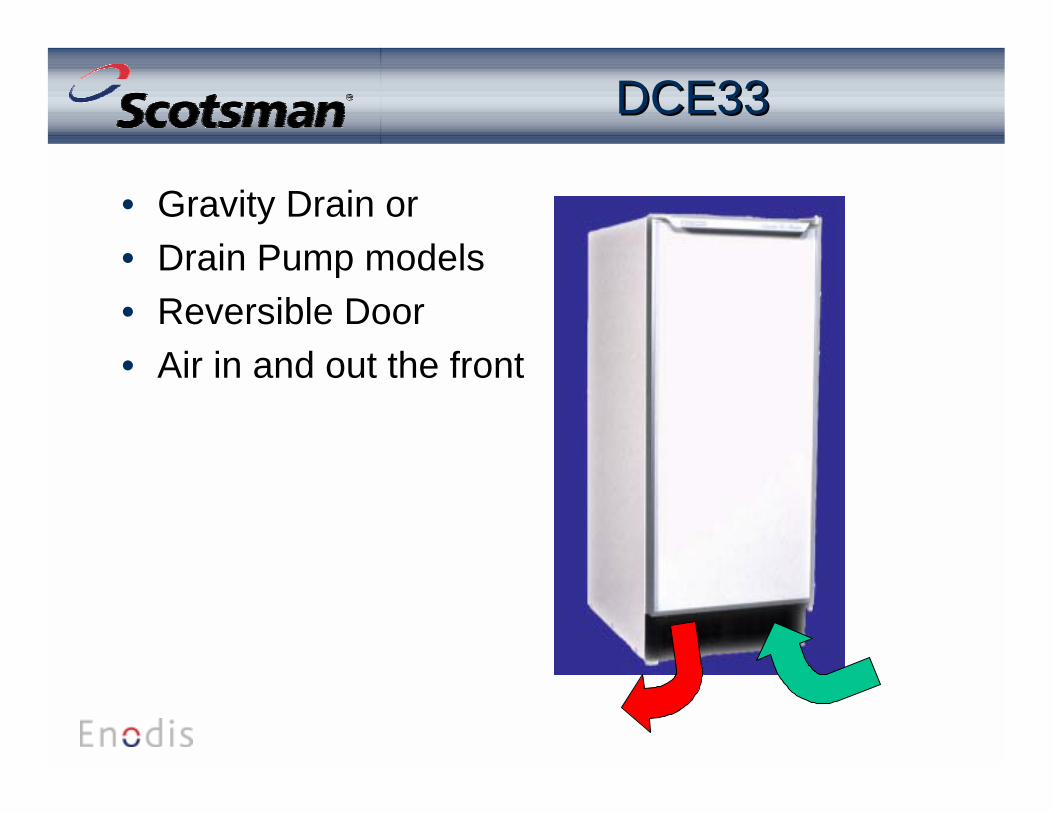
DCE33DCE33
• Gravity Drain or• Drain Pump models• Reversible Door• Air in and out the front
DCE33 InstallationDCE33 Installation
• Water– 1/4” OD copper tubing
• Power– 115/60/1 cord connected
• Drain– Gravity or pump
• Space– 15 & 1/4” wide

WaterConnection
DCE33 InstallationDCE33 Installation
• Air Cooled– Route drain tubing– Route water supply
DCE33 Gravity DrainDCE33 Gravity Drain
• Gravity Drain installation is critical– Connect internally to bin drain– Route flexible tubing out the back– Route with downward pitch to drain receptacle - no
dips, no upward slopes, no traps.• Use rigid tubing if possible• Vent the drain tubing• Must have air-gap at end
DCE33 Drain PumpDCE33 Drain Pump
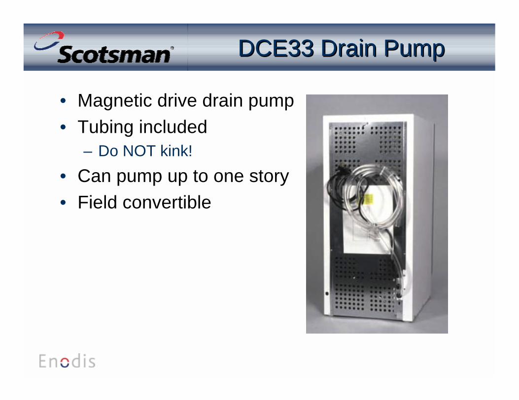
• Magnetic drive drain pump• Tubing included
– Do NOT kink!• Can pump up to one story• Field convertible
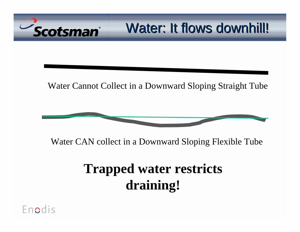
Water: It flows downhill!Water: It flows downhill!
Water Cannot Collect in a Downward Sloping Straight Tube
Water CAN collect in a Downward Sloping Flexible Tube
Trapped water restrictsdraining!
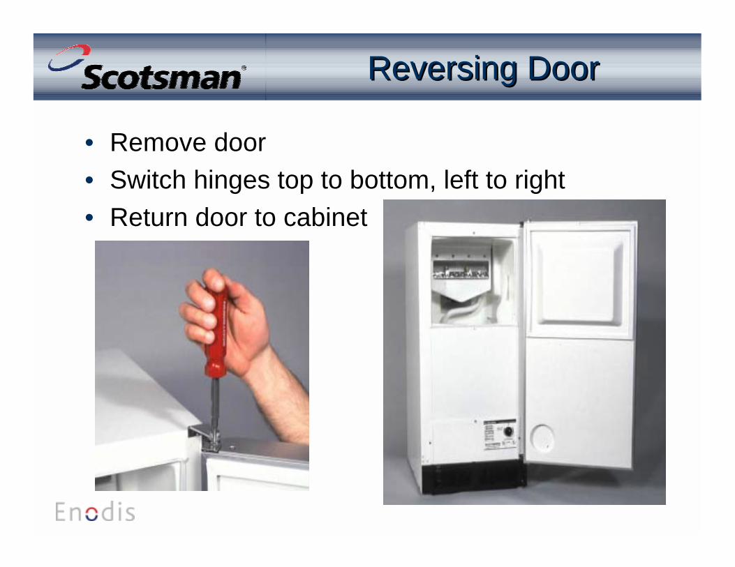
Reversing DoorReversing Door
• Remove door• Switch hinges top to bottom, left to right• Return door to cabinet

DCE33 Initial Start UpDCE33 Initial Start Up
• Check installation• Remove control box cover• Rotate timer CW to Harvest• Rotate bin control to “Operating
Range”• After second batch, check cube
size– Adjust cube size if needed
Timer inHarvestPosition

DCE33DCE33
Cubes too large or too small:
Adjust cube size control.
CW makes cubes larger
CCW makes cubes smaller
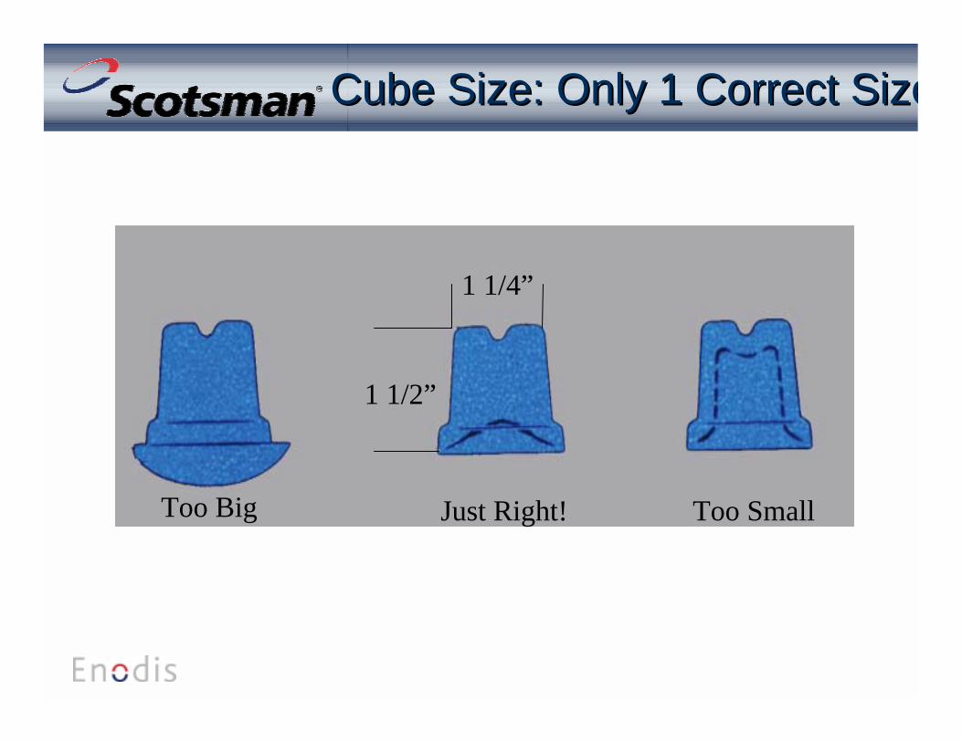
Cube Size: Only 1 Correct SizeCube Size: Only 1 Correct Size
1 1/2”
1 1/4”
Just Right! Too SmallToo Big

InletWaterValve
Cube Size Control Condenser
Bin Stat
Bin
OverflowDrainHose
Reservoir
Curtain
Spray Jets
Front View, without cabinet.
Component LocationComponent Location
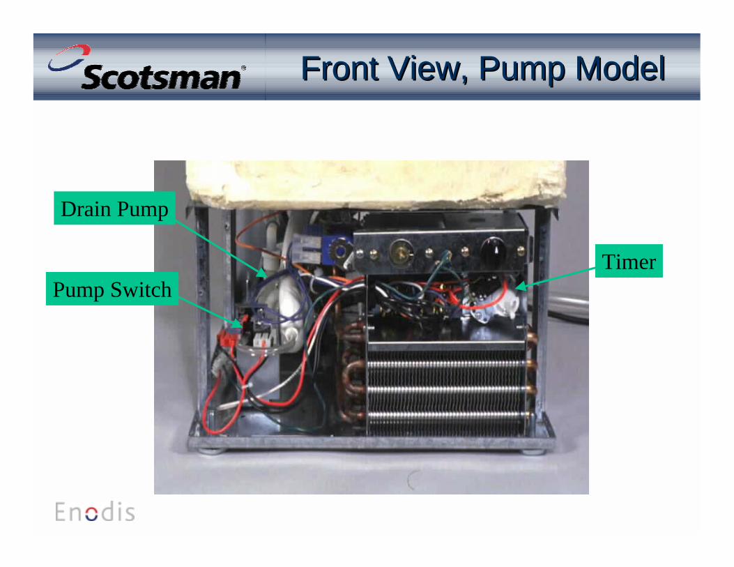
Front View, Pump ModelFront View, Pump Model
Drain Pump
Pump SwitchTimer

Right Side ViewRight Side View
Condenser Fan Shroud Fan Motor

Left Side ViewLeft Side View
DrainPumpMotor
Drain PumpDischarge
Hot Gas Valve
Drain to Pump
Hose toPumpSwitch

Hot Gas Tube
Water Pump
Water Fill Tube
Suction Line/Accumulator
Compressor
Bin Thermostat Capillary Tube
Back ViewBack View
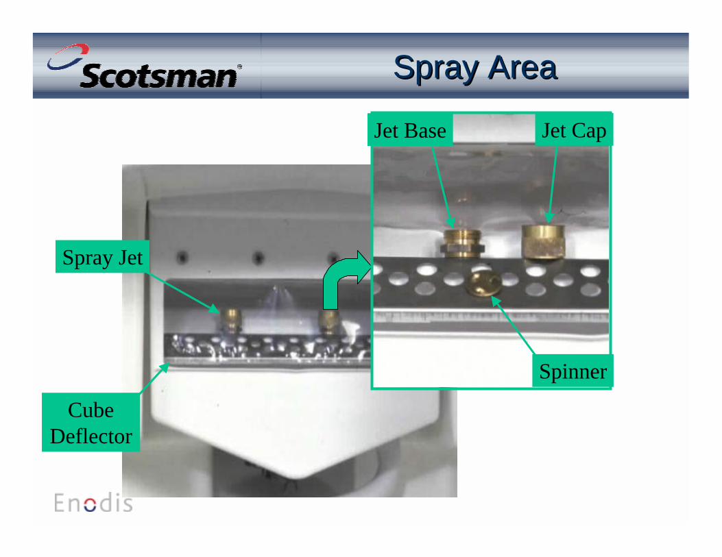
Spray AreaSpray Area
Spinner
Jet Base Jet Cap
Spray Jet
CubeDeflector

CurtainCurtain
• Clear, thin plastic sheet– Flip up to access jets
• Hangs from plastic frame• Frame is attached with 4 screws• Must not be curled or torn

Water Pump & Reservoir Water Pump & Reservoir
Pump Intake
Pump Discharge
Reservoir Overflow
Pump Relief
Pump Fan

How It WorksHow It Works
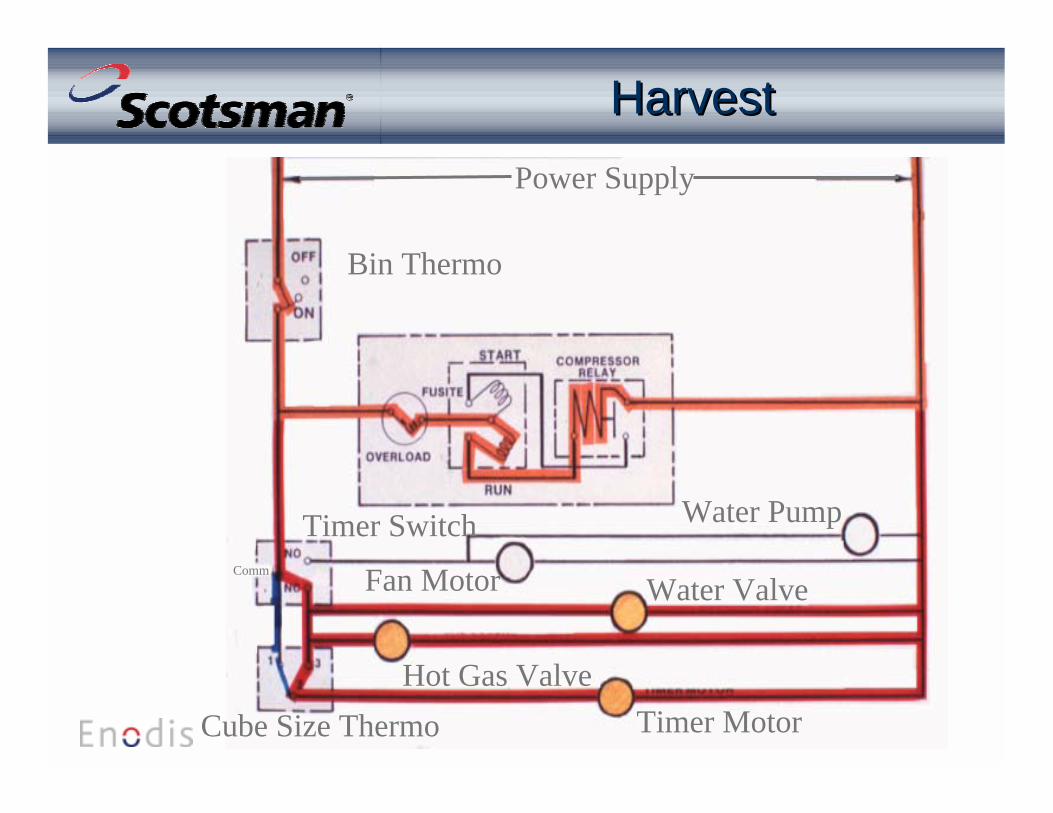
• Water flows in during harvest• Harvest cycle is timed
– Pump is off– Fan is off– Compressor is ON– Hot gas and Water valves are ON
• When the timer cam pushes in the switchbutton, the freeze cycle starts.
Freeze CycleFreeze Cycle
• At the beginning of freeze– Fan is ON– Pump is ON– Compressor is ON– Timer is OFF– Hot gas and water valves are OFF

Cube Size Bulb
Top View of Evaporator
Cube Molds
Cube Size ControlCube Size Control
• Reverse actingthermostat– Senses evaporator
temperature– Closes upon
temperature fall– Connects power to timer
motor– Timer cam rotates to
finish the cycle

Cube Size ThermostatCube Size Thermostat
Beginning Freeze Timed Freeze
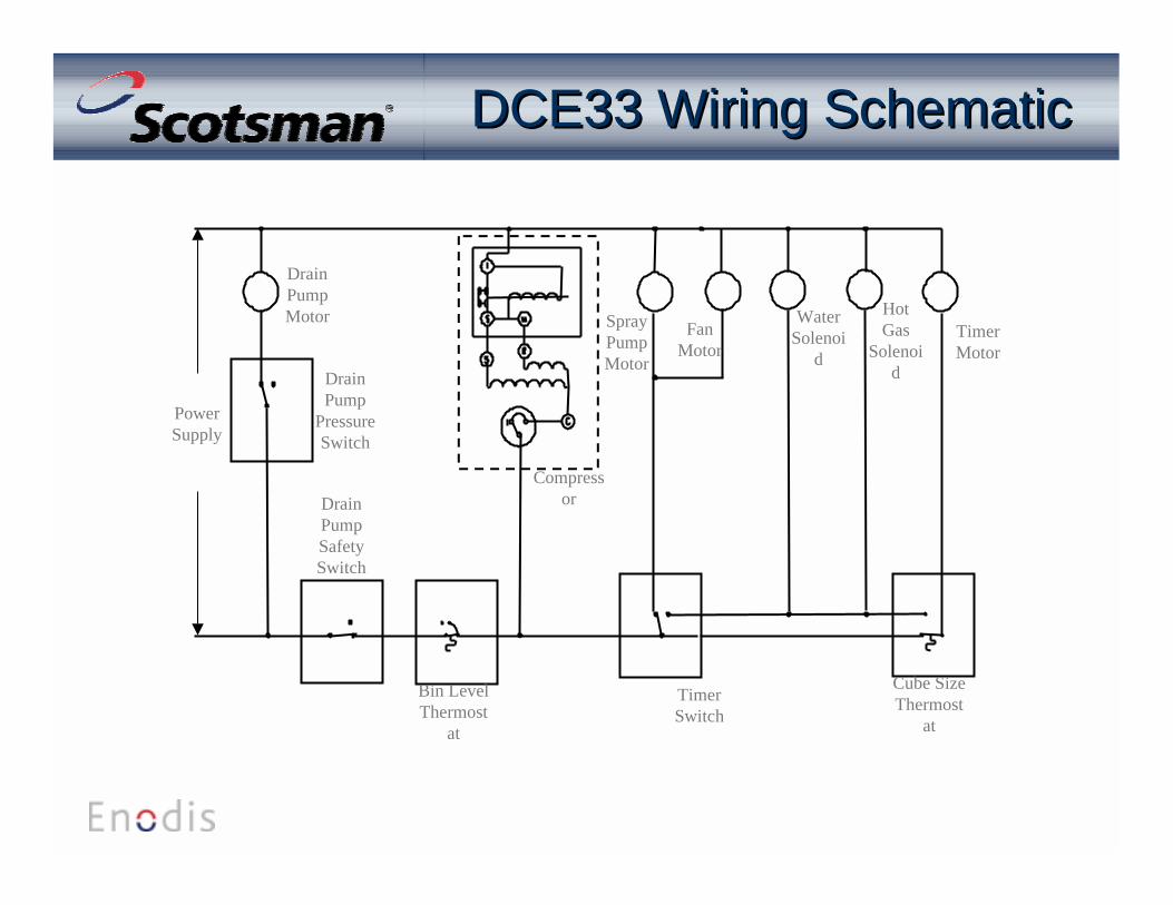
DrainPump
PressureSwitch
DrainPumpSafetySwitch
Bin LevelThermost
at
TimerSwitch
Cube SizeThermost
at
Compressor
DrainPumpMotor Spray
PumpMotor
FanMotor
WaterSolenoi
d
HotGas
Solenoid
TimerMotor
PowerSupply
DCE33 Wiring SchematicDCE33 Wiring Schematic
Power Supply
Timer Motor
Fan Motor
Water Pump
Water Valve
Hot Gas Valve
Bin Thermo
Timer SwitchComm
Cube Size Thermo
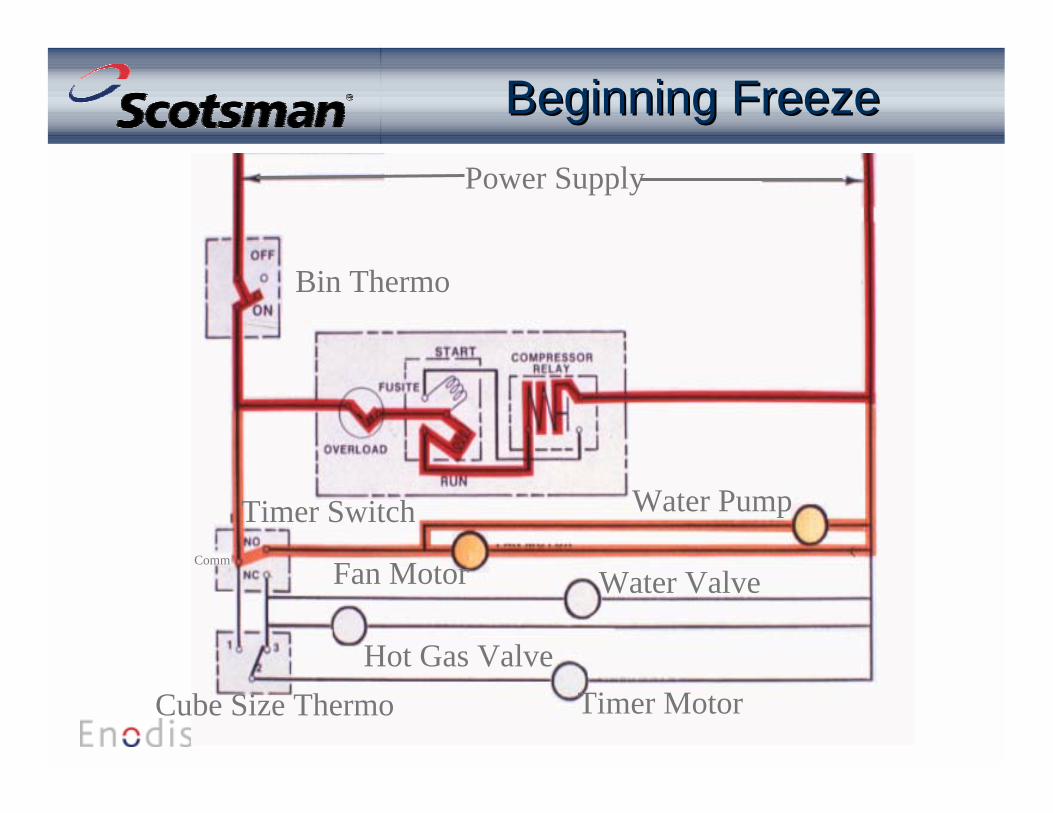
Beginning FreezeBeginning Freeze

Power Supply
Timer Motor
Fan Motor
Water Pump
Water Valve
Hot Gas Valve
Cube Size Thermo
Bin Thermo
Timer SwitchComm
Timed FreezeTimed Freeze
Power Supply
Timer Motor
Fan Motor
Water Pump
Water Valve
Hot Gas ValveCube Size Thermo
Timer SwitchComm
Bin Thermo
HarvestHarvest
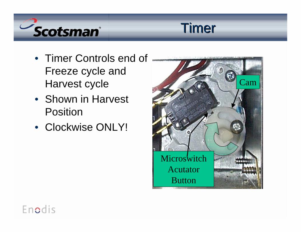
MicroswitchAcutatorButton
Cam
TimerTimer
• Timer Controls end ofFreeze cycle andHarvest cycle
• Shown in HarvestPosition
• Clockwise ONLY!
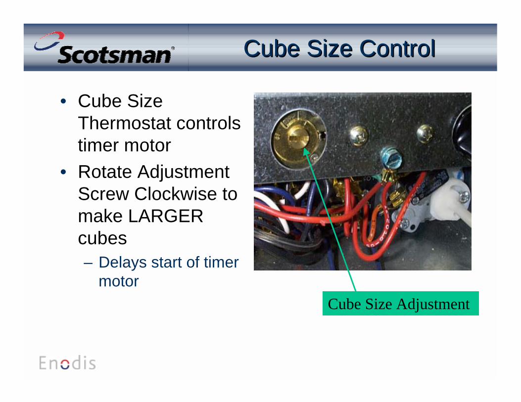
Cube Size Adjustment
Cube Size Control Cube Size Control
• Cube SizeThermostat controlstimer motor
• Rotate AdjustmentScrew Clockwise tomake LARGERcubes– Delays start of timer
motor
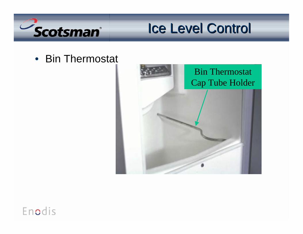
Ice Level ControlIce Level Control
• Bin ThermostatBin Thermostat
Cap Tube Holder
MaintenanceMaintenance
• Frequency depends upon conditions• Water System Cleaning
– Spray Jets– Curtain Inspection
• Water System & Bin Sanitizing• Air Cooled Condenser Cleaning

Water System CleaningWater System Cleaning
• Switch Unit OFF• Discard old ice• Pour 4 ounces of
Scotsman Ice MachineCleaner into Reservoir
• Switch Unit ON• Operate for 2 hours• Rinse bin with hot water
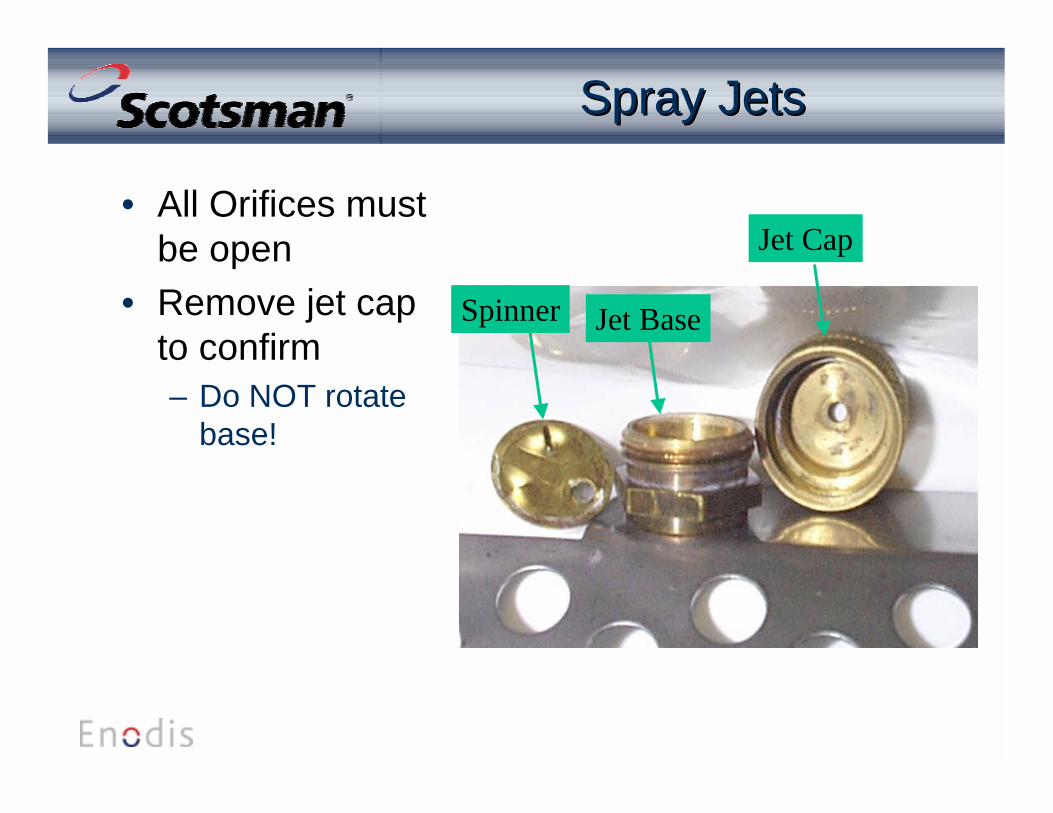
Spray JetsSpray Jets
• All Orifices mustbe open
• Remove jet capto confirm– Do NOT rotate
base!
Spinner Jet Base
Jet Cap

SanitizingSanitizing
• Mix Sanitizer– One ounce of household bleach to Two gallons of
potable water will produce a sanitizing solution– Spray or wash all interior surfaces of the bin and
door with the sanitizing solution– Pour excess down the bin drain– Allow to air dry

Service DiagnosisService Diagnosis
• Cubes are mal-formed– Check spray jets– Check curtain– Check water fill
• Water supply• Inlet Water Valve• Water Filters (if used)
Service DiagnosisService Diagnosis
• Cubes are mal-formed– Water may be leaking out of reservoir
• Check pump hoses• Check curtain
Service DiagnosisService Diagnosis
• Low Capacity– Normal capacity takes about 24 to 36 hours to fill up
& shut off after start up• If slow, check cube count
– Should be 8 full cubes• Check cycle time
– Should be about 1/2 hour» If long, check condenser or» Inlet water valve might be leaking through
• Check bin for proper draining– Accumulating water will melt ice
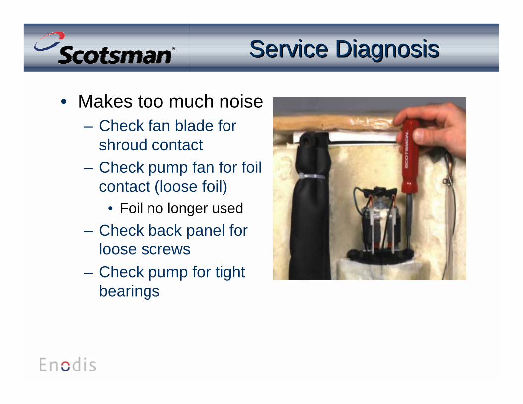
Service DiagnosisService Diagnosis
• Makes too much noise– Check fan blade for
shroud contact– Check pump fan for foil
contact (loose foil)• Foil no longer used
– Check back panel forloose screws
– Check pump for tightbearings
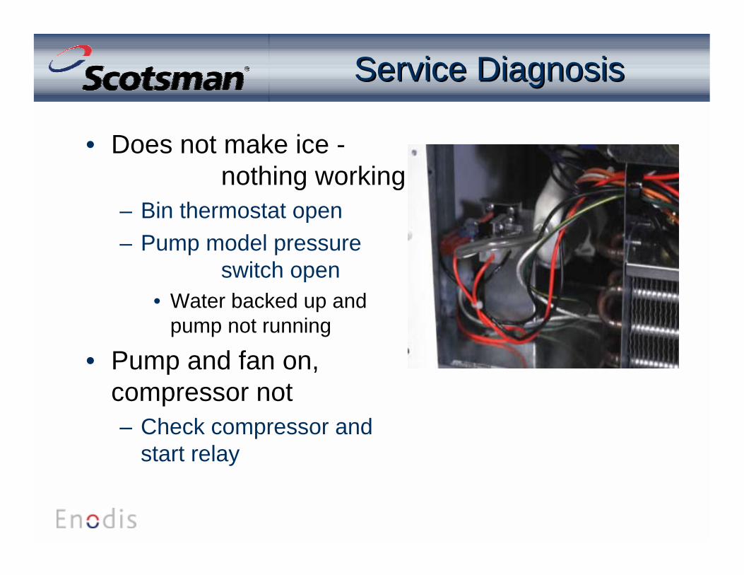
Service DiagnosisService Diagnosis
• Does not make ice - nothing working
– Bin thermostat open– Pump model pressure
switch open• Water backed up and
pump not running
• Pump and fan on,compressor not– Check compressor and
start relay
Service DiagnosisService Diagnosis
• Compressor, fan and pump on, water spraying,no ice– Cube size thermostat not closing
• Too much heat load from water leaking through inletwater valve
• Can’t reject heat due to dirty condenser• Thermostat failed

Service DiagnosisService Diagnosis
• Makes partial cubes– Spray jet dirty– Water level low– Water trapped on top of evaporator
• Weep hole restricted– Low charge because of a refrigerant leak
RefrigerationRefrigeration
• R-134a system– Uses Tecumseh compressor (1/8 HP)– Hot gas bypass to defrost evaporator during harvest– 5 ounce charge– Do not connect high side gauge - too much charge
will go into the hose!– Suction at the end of freeze is about 5 PSIG
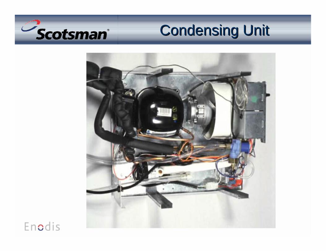
Condensing UnitCondensing Unit
DCE33 SummaryDCE33 Summary
• Compact ice machine• Can be built in• Pump or Gravity Drain model
– Drain pump is magnetic drive - no leaks!• Reversible Door• 8 cubes per cycle• Makes commercial quality ice