dca-2 & dca-2t digital control attenuator rc … rc-16 manual.pdf · dca-2 digital control...
TRANSCRIPT
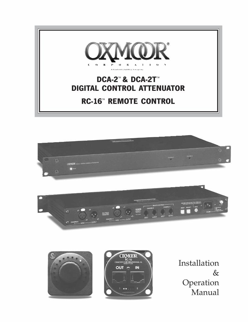
DCA-2™ & DCA-2T™
DIGITAL CONTROL ATTENUATOR
RC-16™ REMOTE CONTROL
Installation&
OperationManual

TABLE OF CONTENTSDCA-2 & RC-16 INTRODUCTION ............................................................................................... 1
DCA-2 CALLOUTS ..................................................................................................................... 2
RC-16 CALLOUTS ..................................................................................................................... 2
DCA-2 BLOCK DIAGRAM ........................................................................................................... 3
DCA-2T BLOCK DIAGRAM ......................................................................................................... 3
DCA-2 SET-UP .......................................................................................................................... 4
RC-16 MOUNTING DATA ........................................................................................................... 4
DCA-2 & RC-16 CONNECTIONS ................................................................................................ 5
DCA-2 & RC-16 CONFIGURATION EXAMPLES ........................................................................... 6
DCA-2 & RC-16 CONFIGURATION EXAMPLES (CONTINUED) ..................................................... 7
DCA-2 & RC-16 CONFIGURATION EXAMPLES (CONTINUED) ..................................................... 8
DCA-2 & RC-16 CONFIGURATION EXAMPLES (CONTINUED) ..................................................... 9
DCA-2 & RC-16 TROUBLESHOOTING........................................................................................ 10
USER NOTES ........................................................................................................................... 11
DCA-2/DCA-2T & RC-16 SPECIFICATIONS ............................................................................... 12
OXMOOR FACTORY SERVICE ................................................................................................... 13
OXMOOR TWO YEAR LIMITED WARRANTY............................................................................... 13
CONTACT OXMOOR ................................................................................................................. 13

Page 1
DCA-2 & RC-16 INTRODUCTION
The Oxmoor DCA-2 Digital Control Attenuator and oneor more RC-16 Remote Control units together constitutea unique, high-quality system for the remote control ofaudio level. The DCA-2 is a compact (1-3/4” high) rackmountable package that can control two discrete audiochannels (90 dB of isolation is provided for two unre-lated programs) or the two channels can be linked to con-trol a single stereo program. Multiple DCA-2s can belinked, and up to 64 discrete channels can thus be con-trolled in a single chain with 1/4 dB tracking tolerancebetween channels. Designed for professional applica-tions, the DCA-2 is equipped with XLR-type input andoutput connections. The DCA-2T outputs are transformerbalanced. Either system is capable of driving 600 ohm orhigher impedance loads; maximum output is +18 dBmterminated, +20 dBu unterminated.
Precise volume control can be provided at as many loca-tions as required. The remote units are easily wired, in“daisy-chain” configuration, using simple modular tele-phone style cables. Up to four RC-16 remotes can be con-nected to a given control input (and that remote, or stringof remotes, can be “daisy- chained” to control up to 64audio channels). The system provides 29 steps of precise1.5 dB attenuation from 0 to -43.5 dB, with a 30th step for90 dB “full kill” attenuation. Virtual display of the setattenuation is simultaneously given at all locations via acircular LED array around the knob on each RC-16Remote Control. The RC-16 can be mounted in a stan-dard two-gang electrical wall box, or a pre-punched 2-gang plate is available from Oxmoor. The maximum cablelength from the DCA-2 to the farthest remote is approxi-mately 2,000 feet (see SPECIFICATIONS, page 13).
The RC-16 is actually a highly sophisticated shaft encoderwhich translates knob movements into a string of digitalpulses; the pulses then alter the level of the digitalattenuator(s) within the DCA-2 chassis. Unlike up/downbuttons, the RCA-16 is sensitive to rate-of-change, andthus the faster the knob is turned, the faster the setting ischanged. As any interconnected RC-16 knob is turned,the LEDs on all remotes in the chain follow until theupper or lower limit is reached. At that point, the knob
will continue to turn, but the level and Virtual Pointerssimply stop changing until any one of the knobs is turnedin the opposite direction. Since there are no mechanicalstops, a knob cannot be “twisted off” if it is turnedbeyond what would be the “stop” positions on a con-ventional level control.
The Oxmoor system includes a number of unique fea-tures. A “Preset” control on the DCA-2 rear panel setsthe degree of attenuation exhibited when the system isfirst powered up, avoiding an unpredictable or unknownturn-on state. One or both channels can be switch-resetback to this “Preset” level at any time. Another rear panelcontrol, labeled “Priority,” sets a level to which thesystem can be temporarily forced by an external switchclosure. Each RC-16 remote has terminals for preset andpriority functions. The switch itself is not included.
Additionally, Channel A & B maximum gains can beadjusted ±15 dB from the nominal unity gain of thesystem via recessed, front-panel controls. For applicationswhere access to one or more remote controls must berestricted, a key switch can be installed in place of ajumper on the back of the RC-16; the key switch mustthen close to activate the RC-16.
Installation of the DCA-2 Digital Control Attenuator andRC-16 Remote Controls is straightforward. However,there are a number of optional configurations. We there-fore recommend that you read this entire manual once,quickly. Note those items which apply to the set-up yourequire, and then read the pertinent sections carefullybefore installing your system. Basic hookup is shown inthe CONNECTIONS section (see page 5). More complexhookups are illustrated and discussed in the CONFIGU-RATION EXAMPLES section (see pages 6 through 9).
• UL and CE listed• Front panel, screwdriver-adjustable gain trims• Electronically balanced, XLR-type inputs• Electronically balanced, XLR-type outputs (DCA-2T only)• +18 dBu input signal levels• +20 dBu output signal levels• Built-in RF suppression• Compact, 1U rack space chassis
DCA-2 DIGITAL CONTROL ATTENUATOR
POWER
CHANNEL A CHANNEL B
1
Page 2
CHASSIS
SERIAL #
POWERFUSEOUTPUT IN OUT IN OUT
REMOTE CONTROLSCHANNEL B CHANNEL A
PRESET PRIORITYCHAN A
INPUT OUTPUT
CHAN B
OXMOORMADE IN USA BY
OXMOOR CORPORATIONBIRMINGHAM, ALABAMA
INPUT
5
DCA-2 CALLOUTS
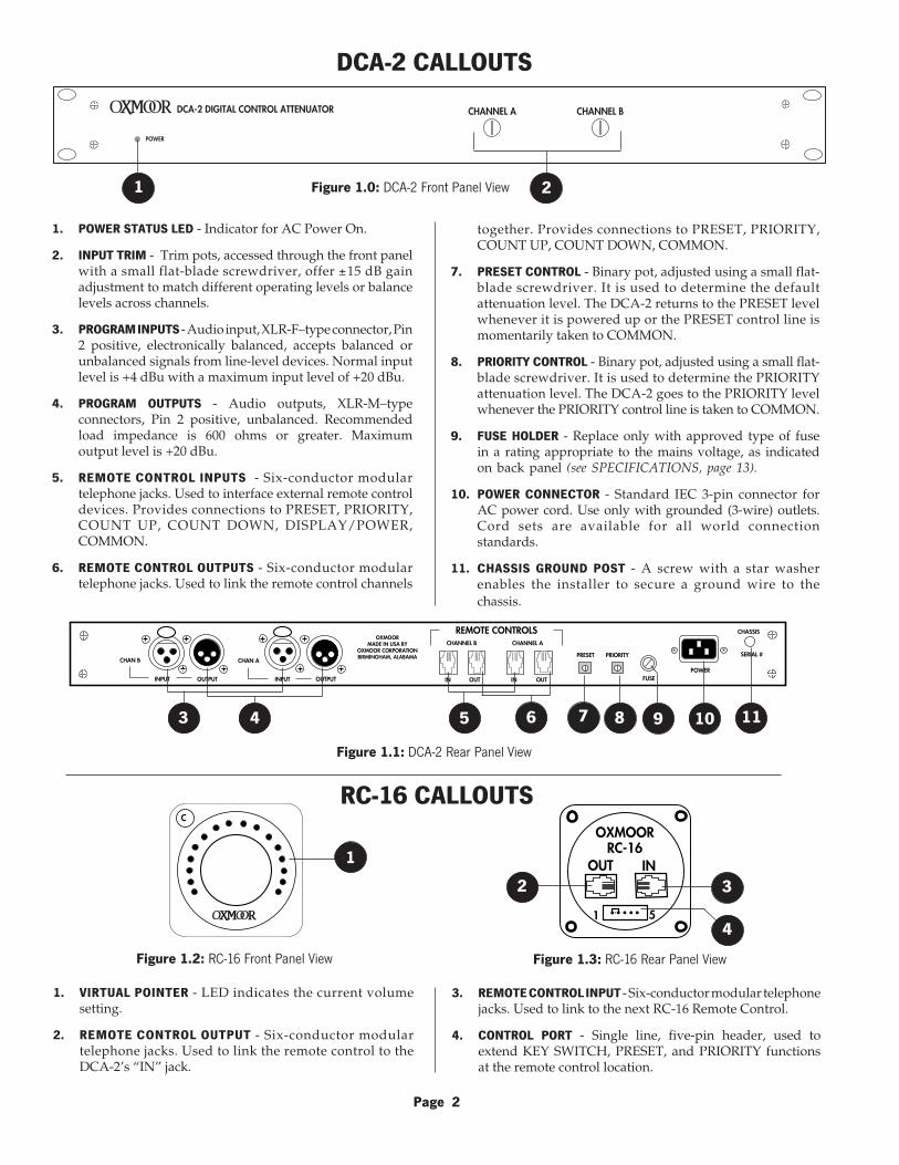
together. Provides connections to PRESET, PRIORITY,COUNT UP, COUNT DOWN, COMMON.
7. PRESET CONTROL - Binary pot, adjusted using a small flat-blade screwdriver. It is used to determine the defaultattenuation level. The DCA-2 returns to the PRESET levelwhenever it is powered up or the PRESET control line ismomentarily taken to COMMON.
8. PRIORITY CONTROL - Binary pot, adjusted using a small flat-blade screwdriver. It is used to determine the PRIORITYattenuation level. The DCA-2 goes to the PRIORITY levelwhenever the PRIORITY control line is taken to COMMON.
9. FUSE HOLDER - Replace only with approved type of fusein a rating appropriate to the mains voltage, as indicatedon back panel (see SPECIFICATIONS, page 13).
10. POWER CONNECTOR - Standard IEC 3-pin connector forAC power cord. Use only with grounded (3-wire) outlets.Cord sets are available for all world connectionstandards.
11. CHASSIS GROUND POST - A screw with a star washerenables the installer to secure a ground wire to thechassis.
Figure 1.0: DCA-2 Front Panel View
1. POWER STATUS LED - Indicator for AC Power On.
2. INPUT TRIM - Trim pots, accessed through the front panelwith a small flat-blade screwdriver, offer ±15 dB gainadjustment to match different operating levels or balancelevels across channels.
3. PROGRAM INPUTS - Audio input, XLR-F–type connector, Pin2 positive, electronically balanced, accepts balanced orunbalanced signals from line-level devices. Normal inputlevel is +4 dBu with a maximum input level of +20 dBu.
4. PROGRAM OUTPUTS - Audio outputs, XLR-M–typeconnectors, Pin 2 positive, unbalanced. Recommendedload impedance is 600 ohms or greater. Maximumoutput level is +20 dBu.
5. REMOTE CONTROL INPUTS - Six-conductor modulartelephone jacks. Used to interface external remote controldevices. Provides connections to PRESET, PRIORITY,COUNT UP, COUNT DOWN, DISPLAY/POWER,COMMON.
6. REMOTE CONTROL OUTPUTS - Six-conductor modulartelephone jacks. Used to link the remote control channels
Figure 1.1: DCA-2 Rear Panel View
63 4 117 9 108
3. REMOTE CONTROL INPUT - Six-conductor modular telephonejacks. Used to link to the next RC-16 Remote Control.
4. CONTROL PORT - Single line, five-pin header, used toextend KEY SWITCH, PRESET, and PRIORITY functionsat the remote control location.
1. VIRTUAL POINTER - LED indicates the current volumesetting.
2. REMOTE CONTROL OUTPUT - Six-conductor modulartelephone jacks. Used to link the remote control to theDCA-2’s “IN” jack.
RC-16 CALLOUTS
2
C
1 INOUT
OXMOORRC-16
1 5
2 3
4
Figure 1.3: RC-16 Rear Panel ViewFigure 1.2: RC-16 Front Panel View

Page 3
DCA-2 BLOCK DIAGRAM
PRESET PRIORITY
CH. A
CH. B
CH. A
CH. B
CH. B
CH. A
3
21
3
21
DAC
DAC
GG
G
INO
UT
INO
UT
ON-BOARD LOGIC
2 1
3
G2 1
3
AUDIO
LOGIC
PRESET PRIORITY
CH. A
CH. B
CH. A
CH. B
CH. B
CH. A
3
21
3
21
DAC
DAC
G
G
G
INO
UT
INO
UT
ON-BOARD LOGIC
2 1
3
G2 1
3
AUDIO
LOGIC
DCA-2T BLOCK DIAGRAM
Figure 2.0: DCA-2 Block Diagram
Figure 2.1: DCA-2T Block Diagram
NOTE: Output transformer
NOTE: Output transformer
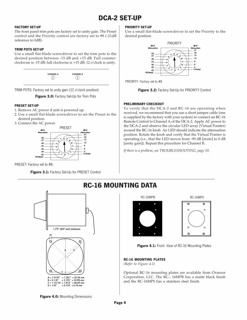
DCA-2 SET-UPFACTORY SET-UPThe front panel trim pots are factory set to unity gain. The Presetcontrol and the Priority control are factory set to #8 (-21dBreference to 0dB).
PRESET SET-UP1. Remove AC power if unit is powered up.2. Use a small flat-blade screwdriver to set the Preset to the
desired position.3. Connect the AC power.
PRIORITY SET-UPUse a small flat-blade screwdriver to set the Priority to thedesired position.
PRELIMINARY CHECKOUTTo verify that the DCA-2 and RC-16 are operating whenreceived, we recommend that you use a short jumper cable (oneis supplied by the factory with your system) to connect an RC-16Remote Control to Channel A of the DCA-2. Apply AC power tothe DCA-2 and observe the circular LED array (Virtual Pointer)around the RC-16 knob. An LED should indicate the attenuationposition. Rotate the knob and verify that the Virtual Pointer isoperating (i.e., that the LED moves from -90 dB [mute] to 0 dB[unity gain]). Repeat this procedure for Channel B.
If there is a problem, see TROUBLESHOOTING, page 10.
TRIM POTS SET-UPUse a small flat-blade screwdriver to set the trim pots to thedesired position between -15 dB and +15 dB. Full counter-clockwise is -15 dB; full clockwise is +15 dB; 12 o’clock is unity.
CHANNEL A CHANNEL B
Figure 3.0: Factory Set-Up for Trim Pots
TRIM POTS: Factory set to unity gain (12 o’clock position)
PRESET: Factory set to #8.
Figure 3.1: Factory Set-Up for PRESET Control
012
34
56
7 8 9A
BC
DE
F
-90 (Mute)
0 (Unity)-3-6-9
-12
-15-18-21
-24-27
-30-33-36-39-42
dB of Attenuation
dB of Attenuation
PRESET
PRIORITY: Factory set to #8.
012
34
56
7 8 9A
BC
DE
F
-90 (Mute)
0 (Unity)-3-6-9
-12
-15-18-21
-24-27
-30-33-36-39-42
dB of Attenuation
dB of Attenuation
Figure 3.2: Factory Set-Up for PRIORITY Control
PRIORITY
RC-16 MOUNTING DATA
RC-16MPB RC-16MPS
Figure 4.0: Mounting Dimensions
RC-16 MOUNTING PLATES(Refer to Figure 4.1)
Optional RC-16 mounting plates are available from OxmoorCorporation, LLC. The RC-, 16MPB has a matte black finishand the RC-16MPS has a stainless steel finish.
Figure 4.1: Front View of RC-16 Mounting Plates
Page 4
1.72" (437 mm) minimum
AB
D
C
A = 1-9/32" = 1.281" = 32.54 mmB = 2-1/8" = 2.125" = 53.98 mmC = 1-13/16" = 1.813" = 46.04 mmD = 1/8" = 0.125" =3.18 mm
12
34
56
PRIORITYDISPLAYCOUNT UPCOUNT DOWNCOMMONPRESET
12
34
56
PRIORITYDISPLAYCOUNT UPCOUNT DOWNCOMMONPRESET
1 2 3 4 5
PRIORITY
COMMONPRESET
Provision for Security Key:A jumper is factory installed.
+–S SHIELD
HIGHLOW
231
XLR PIN-OUT
+–S LOW
HIGH
NC
231
XLR PIN-OUT
BALANCED (DCA-2T VERSION)BALANCED (DCA-2T VERSION)BALANCED (DCA-2T VERSION)BALANCED (DCA-2T VERSION)BALANCED (DCA-2T VERSION)
Page 5
DCA-2 & RC-16 CONNECTIONS
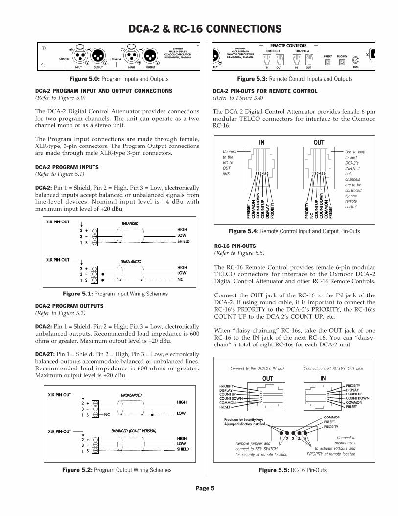
DCA-2 PROGRAM INPUT AND OUTPUT CONNECTIONS(Refer to Figure 5.0)
The DCA-2 Digital Control Attenuator provides connectionsfor two program channels. The unit can operate as a twochannel mono or as a stereo unit.
The Program Input connections are made through female,XLR-type, 3-pin connectors. The Program Output connectionsare made through male XLR-type 3-pin connectors.
DCA-2 PROGRAM INPUTS(Refer to Figure 5.1)
DCA-2: Pin 1 = Shield, Pin 2 = High, Pin 3 = Low, electronicallybalanced inputs accept balanced or unbalanced signals fromline-level devices. Nominal input level is +4 dBu withmaximum input level of +20 dBu.
DCA-2 PIN-OUTS FOR REMOTE CONTROL(Refer to Figure 5.4)
The DCA-2 Digital Control Attenuator provides female 6-pinmodular TELCO connectors for interface to the OxmoorRC-16.
Figure 5.3: Remote Control Inputs and OutputsFigure 5.0: Program Inputs and Outputs
OUTPUT
CHAN A
INPUT OUTPUT
CHAN B
OXMOORMADE IN USA BY
OXMOOR CORPORATIONBIRMINGHAM, ALABAMA
INPUT
DCA-2 PROGRAM OUTPUTS(Refer to Figure 5.2)
DCA-2: Pin 1 = Shield, Pin 2 = High, Pin 3 = Low, electronicallyunbalanced outputs. Recommended load impedance is 600ohms or greater. Maximum output level is +20 dBu.
DCA-2T: Pin 1 = Shield, Pin 2 = High, Pin 3 = Low, electronicallybalanced outputs accommodate balanced or unbalanced lines.Recommended load impedance is 600 ohms or greater.Maximum output level is +20 dBu.
PFUSETPUT IN OUT IN OUT
REMOTE CONTROLSCHANNEL B CHANNEL A
PRESET PRIORITY
OXMOORMADE IN USA BY
OXMOOR CORPORATIONBIRMINGHAM, ALABAMA
123456 123456
PPRE
SET
COM
MO
NCO
UN
T DO
WN
COU
NT U
PD
ISPL
AY
PRIO
RITY
PRIO
RITY
NC
COU
NT U
PCO
UN
T DO
WN
COM
MO
NPR
ESET
OUTOUTOUTOUTOUTINININININ
Figure 5.4: Remote Control Input and Output Pin-Outs
RC-16 PIN-OUTS(Refer to Figure 5.5)
The RC-16 Remote Control provides female 6-pin modularTELCO connectors for interface to the Oxmoor DCA-2Digital Control Attenuator and other RC-16 Remote Controls.
Connect the OUT jack of the RC-16 to the IN jack of theDCA-2. If using round cable, it is important to connect theRC-16’s PRIORITY to the DCA-2’s PRIORITY, the RC-16’sCOUNT UP to the DCA-2’s COUNT UP, etc.
When “daisy-chaining” RC-16s, take the OUT jack of oneRC-16 to the IN jack of the next RC-16. You can “daisy-chain” a total of eight RC-16s for each DCA-2 unit.
Figure 5.5: RC-16 Pin-Outs
Connectto theRC-16OUTjack
Use to loopto nextDCA-2’sINPUT ifbothchannelsare to becontrolledby oneremotecontrol
Connect to the DCA-2’s IN jack Connect to next RC-16’s OUT jack
Remove jumper andconnect to KEY SWITCHfor security at remote location
Connect topushbuttons
to activate PRESET andPRIORITY at remote location
OUTOUTOUTOUTOUT INININININ
Figure 5.2: Program Output Wiring Schemes
Figure 5.1: Program Input Wiring Schemes
UNBALANCEDUNBALANCEDUNBALANCEDUNBALANCEDUNBALANCED
+–S
HIGHLOWSHIELD
+–S
HIGHLOWNC
231
XLR PIN-OUT
231
XLR PIN-OUT UNBALANCEDUNBALANCEDUNBALANCEDUNBALANCEDUNBALANCED
BALANCEDBALANCEDBALANCEDBALANCEDBALANCED
CHASSIS
SERIAL #
POWERFUSEOUTPUT IN OUT IN OUT
REMOTE CONTROLSCHANNEL B CHANNEL A
PRESET PRIORITYCHAN A
INPUT OUTPUT
CHAN B
OXMOORMADE IN USA BY
OXMOOR CORPORATIONBIRMINGHAM, ALABAMA
INPUT
INOUT
OXMOORRC-16
1 5
INOUT
OXMOORRC-16
1 5
INOUT
OXMOORRC-16
1 5
INOUT
OXMOORRC-16
1 5
Page 6
CHASSIS
SERIAL #
POWERFUSEOUTPUT IN OUT IN OUT
REMOTE CONTROLSCHANNEL B CHANNEL A
PRESET PRIORITYCHAN A
INPUT OUTPUT
CHAN B
OXMOORMADE IN USA BY
OXMOOR CORPORATIONBIRMINGHAM, ALABAMA
INPUT
INOUT
OXMOORRC-16
1 5
INOUT
OXMOORRC-16
1 5
INOUT
OXMOORRC-16
1 5
INOUT
OXMOORRC-16
1 5
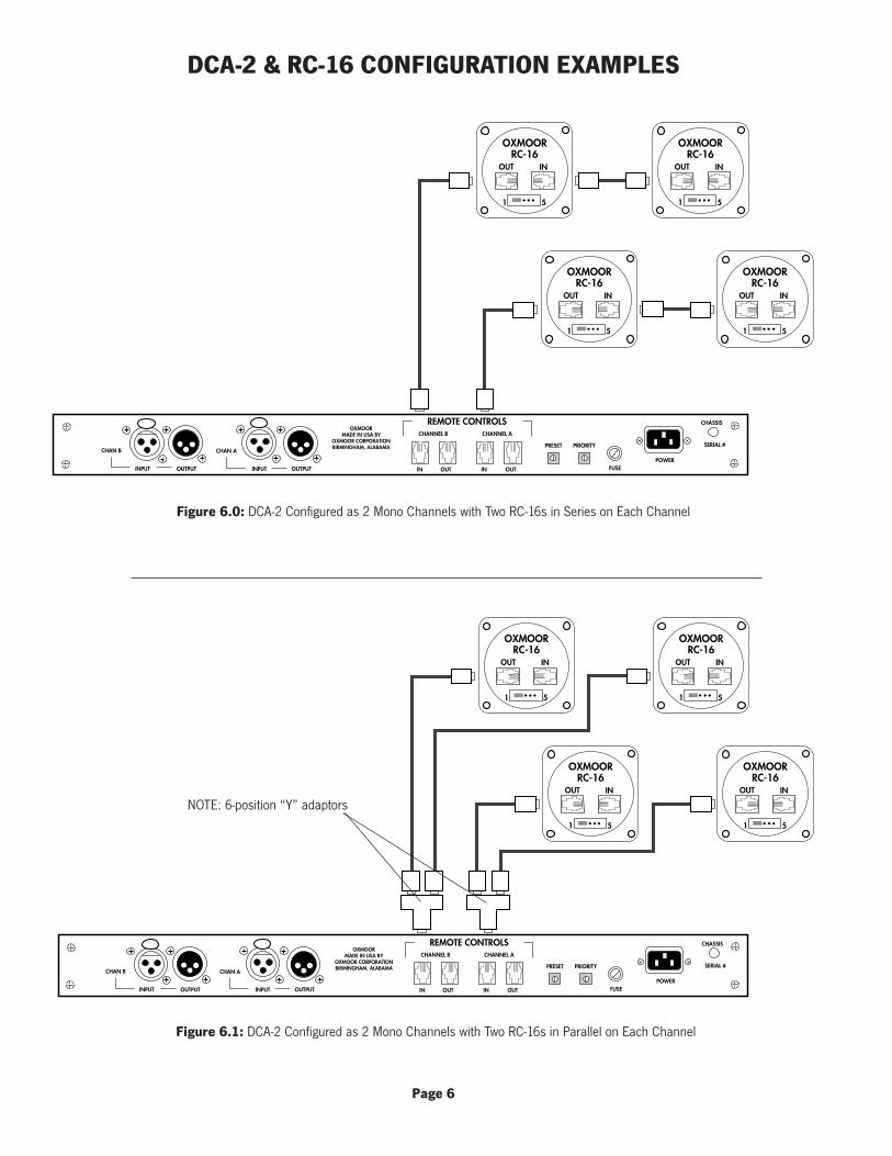
Figure 6.0: DCA-2 Configured as 2 Mono Channels with Two RC-16s in Series on Each Channel
Figure 6.1: DCA-2 Configured as 2 Mono Channels with Two RC-16s in Parallel on Each Channel
DCA-2 & RC-16 CONFIGURATION EXAMPLES
NOTE: 6-position “Y” adaptors

Page 7
Figure 6.2: DCA-2 Configured as Stereo Unit with RC-16s in Series
Figure 6.3: DCA-2 Configured as Stereo Unit with RC-16s in Parallel
CHASSIS
SERIAL #
POWERFUSEOUTPUT IN OUT IN OUT
REMOTE CONTROLSCHANNEL B CHANNEL A
PRESET PRIORITYCHAN A
INPUT OUTPUT
CHAN B
OXMOORMADE IN USA BY
OXMOOR CORPORATIONBIRMINGHAM, ALABAMA
INPUT
INOUT
OXMOORRC-16
1 5
INOUT
OXMOORRC-16
1 5
INOUT
OXMOORRC-16
1 5
INOUT
OXMOORRC-16
1 5
CHASSIS
SERIAL #
POWERFUSEOUTPUT IN OUT IN OUT
REMOTE CONTROLSCHANNEL B CHANNEL A
PRESET PRIORITYCHAN A
INPUT OUTPUT
CHAN B
OXMOORMADE IN USA BY
OXMOOR CORPORATIONBIRMINGHAM, ALABAMA
INPUT
INOUT
OXMOORRC-16
1 5
INOUT
OXMOORRC-16
1 5
DCA-2 & RC-16 CONFIGURATION EXAMPLES (CONTINUED)
NOTE: 6-position “Y” adaptors

Page 8
Figure 6.4: RC-16s in Series Controlling Multiple DCA-2s
Figure 6.5: RC-16s in Parallel Controlling Multiple DCA-2s
DCA-2 & RC-16 CONFIGURATION EXAMPLES (CONTINUED)
CHASSIS
SERIAL #
POWERFUSEOUTPUT IN OUT IN OUT
REMOTE CONTROLSCHANNEL B CHANNEL A
PRESET PRIORITYCHAN A
INPUT OUTPUT
CHAN B
OXMOORMADE IN USA BY
OXMOOR CORPORATIONBIRMINGHAM, ALABAMA
INPUT
CHASSIS
SERIAL #
POWERFUSEOUTPUT IN OUT IN OUT
REMOTE CONTROLSCHANNEL B CHANNEL A
PRESET PRIORITYCHAN A
INPUT OUTPUT
CHAN B
OXMOORMADE IN USA BY
OXMOOR CORPORATIONBIRMINGHAM, ALABAMA
INPUT
INOUT
OXMOORRC-16
1 5
INOUT
OXMOORRC-16
1 5
NOTE: To additional DCA-2s
CHASSIS
SERIAL #
POWERFUSEOUTPUT IN OUT IN OUT
REMOTE CONTROLSCHANNEL B CHANNEL A
PRESET PRIORITYCHAN A
INPUT OUTPUT
CHAN B
OXMOORMADE IN USA BY
OXMOOR CORPORATIONBIRMINGHAM, ALABAMA
INPUT
CHASSIS
SERIAL #
POWERFUSEOUTPUT IN OUT IN OUT
REMOTE CONTROLSCHANNEL B CHANNEL A
PRESET PRIORITYCHAN A
INPUT OUTPUT
CHAN B
OXMOORMADE IN USA BY
OXMOOR CORPORATIONBIRMINGHAM, ALABAMA
INPUT
INOUT
OXMOORRC-16
1 5
INOUT
OXMOORRC-16
1 5
NOTE: To additional DCA-2s
NOTE: 6-position “Y” adaptors

Page 9
DCA-2 & RC-16 CONFIGURATION EXAMPLES (CONTINUED)
CHA
SSIS
SERI
AL
#
POW
ERFU
SEO
UTP
UT
INO
UT
INO
UT
REM
OTE
CO
NTR
OLS
CHA
NN
EL B
CHA
NN
EL A
PRES
ETPR
IORI
TYCH
AN
A
INPU
TO
UTP
UT
CHA
N B
OXM
OO
RM
AD
E IN
USA
BY
OXM
OO
R CO
RPO
RATI
ON
BIRM
ING
HA
M, A
LABA
MA
INPU
T
CHA
SSIS
SERI
AL
#
POW
ERFU
SEO
UTP
UT
INO
UT
INO
UT
REM
OTE
CO
NTR
OLS
CHA
NN
EL B
CHA
NN
EL A
PRES
ETPR
IORI
TYCH
AN
A
INPU
TO
UTP
UT
CHA
N B
OXM
OO
RM
AD
E IN
USA
BY
OXM
OO
R CO
RPO
RATI
ON
BIRM
ING
HA
M, A
LABA
MA
INPU
T
CHA
SSIS
SERI
AL
#
POW
ERFU
SEO
UTP
UT
INO
UT
INO
UT
REM
OTE
CO
NTR
OLS
CHA
NN
EL B
CHA
NN
EL A
PRES
ETPR
IORI
TYCH
AN
A
INPU
TO
UTP
UT
CHA
N B
OXM
OO
RM
AD
E IN
USA
BY
OXM
OO
R CO
RPO
RATI
ON
BIRM
ING
HA
M, A
LABA
MA
INPU
T
CHA
SSIS
SERI
AL
#
POW
ERFU
SEO
UTP
UT
INO
UT
INO
UT
REM
OTE
CO
NTR
OLS
CHA
NN
EL B
CHA
NN
EL A
PRES
ETPR
IORI
TYCH
AN
A
INPU
TO
UTP
UT
CHA
N B
OXM
OO
RM
AD
E IN
USA
BY
OXM
OO
R CO
RPO
RATI
ON
BIRM
ING
HA
M, A
LABA
MA
INPU
T
INO
UT
OXM
OO
RRC
-16
15
Figu
re 6
.6: R
C-1
6 Se
lect
ing
One
of M
ultip
le D
CA-
2s to
Con
trol
6-C
ondu
ctor
Cab
le6P 6
T Sw
itch

DCA-2 & RC-16 TROUBLESHOOTING
Page 10
SYMPTOM POSSIBLE CAUSE & CURE
No signal comes out ofthe DCA-2 with signalapplied to the input(s).
Power is not present. Check POWER indicator on front panel, rear-panel fuse,and AC outlet.
PRESET is turned down all the way to “kill” the sound. Try adjusting anRC-16.
PRIORITY is turned down all the way to “kill,” and a PRIORITY switch is closedsomewhere in the system. Try unplugging the REMOTE CONTROL INPUTcables from the DCA-2. Power down the unit, set PRIORITY level to #8, andreapply power.
Signal level is too low,even with the RC-16set at MAXIMUM.
The recessed gain trim control(s) on the DCA-2 front panel are turned down.Readjust them.
PRIORITY is turned down and a PRIORITY switch somewhere in the system isclosed. Try unplugging the REMOTE CONTROL INPUT cables from the DCA-2.Power down the unit, set PRIORITY level to #8, and reapply power.
The input level to the DCA-2 is too low. Check output of the device feeding it.
Signal level is so highthat the RC-16 mustbe set nearly toMINIMUM gain.
Recessed gain trim control(s) on the DCA-2 front panel are turned up. Readjust.
The input level to the DCA-2 is too high. Check output of the device feeding it.
Audio is distorted,regardless of the levelsetting.
The level applied to the DCA-2 is too high. Be sure it is not over +20 dBu. Turningdown the front panel gain trim may yield the correct DCA-2 output level, but itdoes not prevent overdrive of the input stage.
The DCA-2 output is terminated with an impedance below 600 ohms.
The signal applied to the DCA-2 is already distorted. Check it with the DCA-2 outof the circuit.
None of the RC-16salter the level, and theVirtual Pointersremain fixed.
The PRESET or PRIORITY and GROUND contacts on an RC-16 or theinterconnecting cable are shorted together. Try connecting one RC-16 directly tothe DCA-2 REMOTE CONTROL INPUT with a known good cable and see if thisworks. If so, look for the problem in the rest of the system.
One or more of theRC-16s is inoperative.
Two linked channelsdon’t track with thesame levels.
Levels move in oppo-site directions on twoDCA-2 channels.
A security key (or the jumper in its place) is not installed.
A control cable is miswired.
The input trim pots (DCA-2 front panel) are set differently.
The control signals for the two channels were linked after the DCA-2 was turnedon. Power down the unit, then reapply power.
A link cable is miswired between the two channels. The polarity should bereversed.

Page 11
USER NOTES
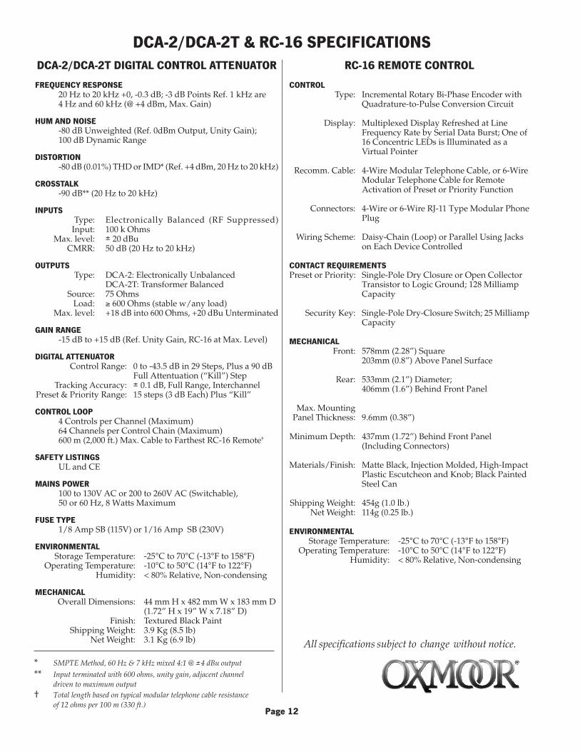
DCA-2/DCA-2T & RC-16 SPECIFICATIONS
All specifications subject to change without notice.
DCA-2/DCA-2T DIGITAL CONTROL ATTENUATOR
FREQUENCY RESPONSE20 Hz to 20 kHz +0, -0.3 dB; -3 dB Points Ref. 1 kHz are4 Hz and 60 kHz (@ +4 dBm, Max. Gain)
HUM AND NOISE-80 dB Unweighted (Ref. 0dBm Output, Unity Gain);100 dB Dynamic Range
DISTORTION-80 dB (0.01%) THD or IMD* (Ref. +4 dBm, 20 Hz to 20 kHz)
CROSSTALK-90 dB** (20 Hz to 20 kHz)
INPUTSType: Electronically Balanced (RF Suppressed)
Input: 100 k OhmsMax. level: ± 20 dBu
CMRR: 50 dB (20 Hz to 20 kHz)
OUTPUTSType: DCA-2: Electronically Unbalanced
DCA-2T: Transformer BalancedSource: 75 Ohms
Load: ≥ 600 Ohms (stable w/any load)Max. level: +18 dB into 600 Ohms, +20 dBu Unterminated
GAIN RANGE-15 dB to +15 dB (Ref. Unity Gain, RC-16 at Max. Level)
DIGITAL ATTENUATORControl Range: 0 to -43.5 dB in 29 Steps, Plus a 90 dB
Full Attentuation (“Kill”) StepTracking Accuracy: ± 0.1 dB, Full Range, Interchannel
Preset & Priority Range: 15 steps (3 dB Each) Plus “Kill”
CONTROL LOOP4 Controls per Channel (Maximum)64 Channels per Control Chain (Maximum)600 m (2,000 ft.) Max. Cable to Farthest RC-16 Remote†
SAFETY LISTINGSUL and CE
MAINS POWER100 to 130V AC or 200 to 260V AC (Switchable),50 or 60 Hz, 8 Watts Maximum
FUSE TYPE1/8 Amp SB (115V) or 1/16 Amp SB (230V)
ENVIRONMENTALStorage Temperature: -25°C to 70°C (-13°F to 158°F)
Operating Temperature: -10°C to 50°C (14°F to 122°F)Humidity: < 80% Relative, Non-condensing
MECHANICALOverall Dimensions: 44 mm H x 482 mm W x 183 mm D
(1.72” H x 19” W x 7.18” D)Finish: Textured Black Paint
Shipping Weight: 3.9 Kg (8.5 lb)Net Weight: 3.1 Kg (6.9 lb)
Page 12
* SMPTE Method, 60 Hz & 7 kHz mixed 4:1 @ ±4 dBu output
** Input terminated with 600 ohms, unity gain, adjacent channeldriven to maximum output
† Total length based on typical modular telephone cable resistanceof 12 ohms per 100 m (330 ft.)
RC-16 REMOTE CONTROL
CONTROLType: Incremental Rotary Bi-Phase Encoder with
Quadrature-to-Pulse Conversion Circuit
Display: Multiplexed Display Refreshed at LineFrequency Rate by Serial Data Burst; One of16 Concentric LEDs is Illuminated as aVirtual Pointer
Recomm. Cable: 4-Wire Modular Telephone Cable, or 6-WireModular Telephone Cable for RemoteActivation of Preset or Priority Function
Connectors: 4-Wire or 6-Wire RJ-11 Type Modular PhonePlug
Wiring Scheme: Daisy-Chain (Loop) or Parallel Using Jackson Each Device Controlled
CONTACT REQUIREMENTSPreset or Priority: Single-Pole Dry Closure or Open Collector
Transistor to Logic Ground; 128 MilliampCapacity
Security Key: Single-Pole Dry-Closure Switch; 25 MilliampCapacity
MECHANICALFront: 578mm (2.28”) Square
203mm (0.8”) Above Panel Surface
Rear: 533mm (2.1”) Diameter;406mm (1.6”) Behind Front Panel
Max. MountingPanel Thickness: 9.6mm (0.38”)
Minimum Depth: 437mm (1.72”) Behind Front Panel(Including Connectors)
Materials/Finish: Matte Black, Injection Molded, High-ImpactPlastic Escutcheon and Knob; Black PaintedSteel Can
Shipping Weight: 454g (1.0 lb.)Net Weight: 114g (0.25 lb.)
ENVIRONMENTALStorage Temperature: -25°C to 70°C (-13°F to 158°F)
Operating Temperature: -10°C to 50°C (14°F to 122°F)Humidity: < 80% Relative, Non-condensing

Oxmoor DCA-2 & DCA-2T Digital Control Attenuator
For service information contact:
OXMOOR FACTORY SERVICE
Additional Installation & Operation Manuals are available from Oxmoor. Contact theOxmoor Sales Department for pricing and other ordering information. Consultwarranty statement for cautions concerning unauthorized service.
Oxmoor Product Service Department309 Cahaba Valley Parkway
Birmingham, Alabama 35124E-mail: [email protected]
Telephone: (205) 982-8200Toll Free: 1 (800) 262-6898Fax: (205) 982-8250Internet: www.oxmoor.com
Oxmoor Corporation, LLC, 309 Cahaba Valley Parkway, Birmingham, AL 35124 USA
Toll Free 1 (800) 262-6898 Telephone (205) 982-8200 Fax (205) 982-8250 E-mail [email protected]
CONTACTCONTACTCONTACTCONTACTCONTACTOXMOOROXMOOROXMOOROXMOOROXMOOR
For 24-hour access to product specs and information visit Oxmoor's complete product line on the internet at www.oxmoor.com.
Oxmoor is a registered trademark of Oxmoor Corporation, LLC.
Specifications and design are subject to change without notice.
OXMOOR TWO YEAR LIMITED WARRANTY
Oxmoor warrants that each Oxmoor electronic product shall be free from defects in workmanshipand materials and will, at its option, repair or replace any part of the product without chargeprovided the product is delivered to Oxmoor within two years of date of original purchase fromor delivery by an authorized Oxmoor dealer. Excluded from this warranty are finish andappearance items and malfunction resulting from abuse, from use that is not in accordance withinstructions, or operation under other than specified conditions. Also excluded are incidental orconsequential damages except where precluded by applicable law. This warranty provides thecustomer with specific legal rights; there may also be other rights which vary from state to state.
Repair by other than Oxmoor Factory Service Department or its authorized service agency,unauthorized modification, or the removal or defacing of the serial number will void thiswarranty.
Products returned for factory warranty service must be prepaid and packaged in such a way as toinsure safe transit and must be accompanied by a sales slip or other valid proof of purchase date.
PRIOR AUTHORIZATION FROM OXMOOR IS REQUIRED FOR RETURN. Contact Oxmoor fora Return Authorization (R.A.) Number and shipping information before returning product forservice.
Rev. 3.2/072501 Part Number:1700001