dc3 ground facilities dc3 science team meeting …...2012/02/21 · –imet-1-ab 403 mhz gps...
TRANSCRIPT

DC3 Ground Facilities Alabama
Larry Carey University of Alabama in Huntsville
(UAHuntsville) With contributions from Rich Blakeslee (NASA MSFC),
Walt Petersen (NASA GSFC), Elise Schultz (UAHuntsville) and Kevin Knupp (UAHuntsville)
21-22 February 2012 DC3 Science Team Meeting

DC3 Alabama Ground Facilities • UAHuntsville
– Advanced Radar for Meteorological and Operational Research (ARMOR) C-band dual-polarimetric radar
– Mobile Alabama X-band (MAX) dual-polarimetric radar – Mobile Integrated Profiling System (MIPS) – iMET-3150 GPS sounding system
• NASA MSFC – Northern Alabama - Lightning Mapping Array (NA-LMA) – Other lightning data (Regional/Global LF/VLF networks such as
Vaisala NLDN, Vaisala GLD360, Earth Networks ENTLN)
• Other – Army Redstone Arsenal 12z sounding – KHTX Hytop (also KBMX, KOHX, KFFC) WSR-88D S-band
upgraded dual-polarimetric radars – KGWX WSR-888D (not upgraded)
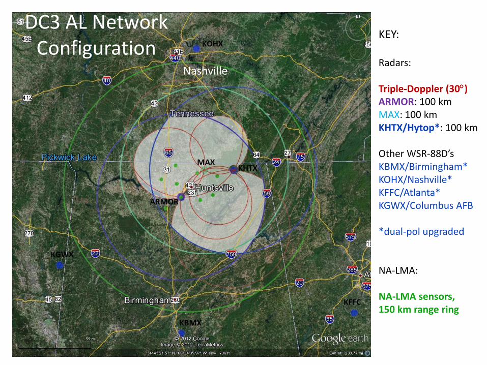
DC3 AL Network Configuration
KEY: Radars: Triple-Doppler (30) ARMOR: 100 km MAX: 100 km KHTX/Hytop*: 100 km Other WSR-88D’s KBMX/Birmingham* KOHX/Nashville* KFFC/Atlanta* KGWX/Columbus AFB *dual-pol upgraded NA-LMA: NA-LMA sensors, 150 km range ring
Nashville

UAHuntsville ARMOR: Advanced Radar for Meteorological and Operational Research.
• Location : Huntsville Intl. Airport •Altitude (antenna MSL): 206 m
•Transmit frequency: 5625 MHz (C-band) •Peak Power: 350 kW (Magnetron) •Pulse width: 0.4 – 2.0 ms •Maximum PRF: 250-2000 s-1
•Antenna Diameter 3.7 m (12 ft CF Parabolic) •Antenna Beam width: 1.0o • First side-lobe: -30 dB •Cross-pol isolation: < -41 dB •Maximum rotation rate: 36o s-1 •Transmit polarization: Simultaneous H and V, [or H] •Receive polarization: Vaisala Sigmet dual-channel; H + V, or H • Signal Process: Vaisala Sigmet RVP/8
•Variables: Z, Vr, W, Zdr, rHV, fdp, Kdp,, [LDR]
• 2002: NWS Doppler WSR-74C donated to UAHuntsville • 2004: Upgraded to dual-polarimetric using the SIGMET Antenna Mounted Receiver • 2005: Upgrade to solid state transmitter by Baron Services • 2006: Upgrade to high performance Seavey antenna and Orbit pedestal with integration by Baron Services • More information regarding the ARMOR can be found at http://nsstc.uah.edu/armor/
ARMOR at HSV
C-band Dual-Polarimetric
http://www.nsstc.uah.edu/ARMOR/

http://www.nsstc.uah.edu/ARMOR/
ARMOR
• Continuous research operations/scanning
• RVP-8 IRIS control from UAHuntsville NSSTC network computer
• 2 person team: 1 Radar Operator, 1 Nowcaster & Comms
• Real-time quality control, propagation correction, preliminary product generation (HID, QPE)

6
MAX: Mobile Alabama X-band dual polarimetric Doppler Radar
Oct. 2006: Initial procurement of hardware
Nov. 2006 - Fall 2007: Construction
Fall 2007 - Winter 2008: Shakedown/field ready
• Transmit frequency: 9450 MHz (H+V, H)
• Peak Power: 250 kW
• Pulse width: 0.4 – 2.0 ms
• Min/Max PRF: 250 / 2000 s-1
• Antenna Diameter 2.4 m (8 ft, CF Parabolic)
• Antenna Gain 44.5 dB
• Antenna Beam width: 1o
• First side-lobe: -31 dB
• Cross-pol isolation: <-36 dB
• Receiver polarization: RVP/8
• Variables: Z, V, W, ZDR, fDP, KDP, rhv, LDR
Radar Development
• Tx/Rx/Ant. Design/Integration: Baron
Services, Huntsville
• MP-61 Pedestal (Radio Research): UAH
with prep. work and checkout by Mr. Bob
Bowie, CSU-CHILL
• Truck/generator/data system: UAH
http://vortex.nsstc.uah.edu/mips/max/
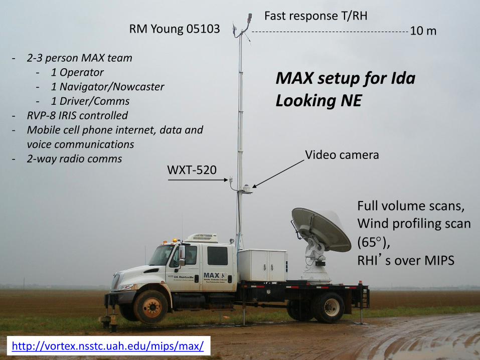
MAX setup for Ida Looking NE
WXT-520 Video camera
RM Young 05103 Fast response T/RH
Full volume scans, Wind profiling scan
(65), RHI’s over MIPS
10 m
http://vortex.nsstc.uah.edu/mips/max/
- 2-3 person MAX team - 1 Operator - 1 Navigator/Nowcaster - 1 Driver/Comms
- RVP-8 IRIS controlled - Mobile cell phone internet, data and
voice communications - 2-way radio comms

DC3 AL Research (ARMOR-MAX) dual-polarimetric, Dual-Doppler Network
Radar Characteristic ARMOR (C-band) MAX (X-band) Location Huntsville Intl. Airport Mobile (truck-based) Transmit frequency 5625 MHz (magnetron) 9450 MHz (magnetron) Peak Power 350 kW 250 kW
Pulse width 0.4, 0.8, 1.0, 2.0 µs 0.4, 0.8, 1.0, 2.0 ms
PRF Range 250-2000 Hz 250-2000 Hz
Antenna diameter/beamwidth 3.7 m (CF parabolic)/ 1.0 2.44 m (CF parabolic)/0.95 First side-lobe -30 dB -31 dB
Transmit polarization mode 1. STAR (H+V) or 2. H 1. STAR (H+V) or 2. H
Receive polarization H and V H and V
Signal Processor, Controller VAISALA-SIGMET RVP/8, RCP/8 VAISALA-SIGMET RVP/8, RCP/8
Variables (depends on transmit mode 1 or 2)
1. Zh, Vr, W, Zdr, dp/Kdp, rHV or 2. Zh, Vr, W, LDR
1. Zh, Vr, W, Zdr, dp/Kdp, rHV or 2. Zh, Vr, W, LDR
Table 4. NSSTC (UAHuntsville and NASA MSFC) radar specifications.
MAX
ARMOR at HSV
Max located near New Market, AL.
Dynamics and Microphysics

ARMOR Pulse Storm: Dual-pol, HID and IC and CG Lightning Initiation
•ZDR and ZH (> 25 dBZ)
•LMA Sources (“+”) •NCAR Fuzzy HID 18 Minutes to 1rst IC
7 more minutes to 1rst CG Sequence
• 1643 UTC: elevated rain core ZDR > 2 dB to T = -10oC
• 1648-1652 UTC: Freezing (reduced ZDR) mixed phase
• 1652 UTC: Rapid top growth
• 1655 UTC: First IC
• 1657 UTC: Top still growing
• 1657-1701 UTC Core descent
• 1702 UTC: First CG; comes to
ground in mixed phase core
• 1703 UTC: Last CG • 1705 UTC: Last IC

10 kW generator
915 MHz Doppler wind profiler
Microwave Profiling
Radiometer
X-band Profiling
Radar
Lidar Ceilometer
Mobile Integrated Profiling System (MIPS)
http://vortex.nsstc.uah.edu/mips/

Mobile Integrated Profiling System (MIPS)
2-3 person crew

iMET-3150 (403 MHz GPS) Upper Air Sounding System
• iMetOS (Windows PC based) provides – Flight status display – Radiosonde data display – Real-time processing, quality control and reporting of met data – Graphical output (e.g., Skew-T Log-P) of T, Td, RH, wind speed & direction – Playback of previously recorded flights – Data editing and archiving – WMO, STANAG and custom reports
• iMet-1 radiosonde
– Factory calibrated, 1 year accuracy
– meets the current NWS radiosonde specification (NWS-J070-RS-SP005C.)

• 60 radiosondes for DC3 (40/20 reserved for flight/non-flight operations)
– iMet-1-AB 403 MHz GPS Radiosonde C/A code GPS receiver with solid state pressure sensor
– De-reeler, pre-wound with 30 m string
– 300 gm Latex meteorological balloon (24.7 km burst altitude), parachute
2-3 person crew


transitioning unique NASA data and research technologies to the NWS transitioning unique NASA data and research technologies to the NWS
15
NASA’s North Alabama Lightning
Mapping Array (NALMA)
• Network of 11 detectors centered about Huntsville, AL (NMT heritage)
• Operational since ~ November 2001
• Detects VHF (76-82 MHz, “Ch. 5”) radiation along the lightning channel - up to 1000s of sources per flash
• Computes 4-D location of all electrical discharges (“flashes”)
within LMA (CG…and IC, CC, CA)
Example of lightning
flash detected by
NALMA

transitioning unique NASA data and research technologies to the NWS transitioning unique NASA data and research technologies to the NWS
16
LMA Hardware
New Mexico Tech System
LMA Sensor Sites
VHF ground plane antenna
Sensor electronics / site computer (first generation)
Communications (mostly 2.4 GHz wireless Ethernet network link)
Relay Sites and Central Station
PC router (up to 4 network links)
Communications (multiple antennas require great care in channel selection)
Cell phone modems used at some sites

transitioning unique NASA data and research technologies to the NWS transitioning unique NASA data and research technologies to the NWS
17
LMA Site Installations
Sites selected on basis of noise level, ability to establish wireless com link, and low / no cost access
Installations include: water towers, public/private radio towers, user supplied towers/masts, utility poles, even a firetower and a building
User supplied tower (Owen)
Utility pole (AAMU)
Commercial radio tower (Drake)
Water tower (Keel)

transitioning unique NASA data and research technologies to the NWS
18 18
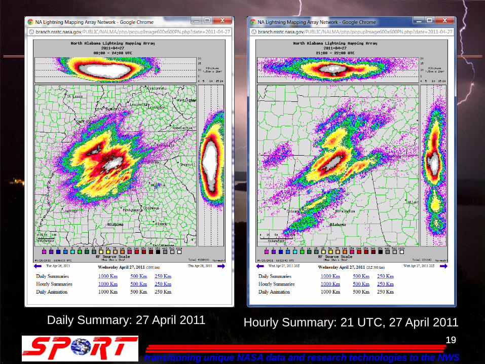
North Alabama
LMA
http://branch.nsstc.nasa.gov/PUBLIC/NALMA/
transitioning unique NASA data and research technologies to the NWS
19 19
Daily Summary: 27 April 2011 Hourly Summary: 21 UTC, 27 April 2011

20
Example of LMA Flash
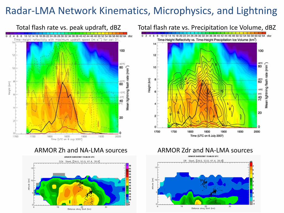
Total flash rate vs. Precipitation Ice Volume, dBZ Total flash rate vs. peak updraft, dBZ
ARMOR Zh and NA-LMA sources ARMOR Zdr and NA-LMA sources
Radar-LMA Network Kinematics, Microphysics, and Lightning

ARMOR T-Storm Sequence: 25 July 2007 Rain/hail mix, large drops
Z rhv ZDR
Vert. Develop/Mixed Phase Ext.Mixed phase Glaciating Glaciated
Mixed phase and glaciation evolution in T-storm
Toggle through images (time)
Mixed phase extension
Glaciating
Glaciated

DC3 AL Research (ARMOR-MAX) dual-polarimetric, Dual-Doppler Network
• Secondary configuration
• MAX at Courtland, AL site west of HSV
• Site visibility and access not as good as New Market (primary MAX site)
• Coverage of LMA network not as good as New Market