dc to 1 mhz analog fiber optic transmission...
TRANSCRIPT

1
OPERATOR'S MANUAL
MODEL 5612/5613DC TO 1 MHz ANALOG
FIBER OPTIC TRANSMISSIONSYSTEM

2
Corporate Headquarters700 Chestnut Ridge RoadChestnut Ridge, NY 10977-6499Tel: (914) 578-6013 Fax: (914) 578-5984
European Headquarters2, rue du Pre-de-la-FontaineP.O. Box 341CH-1217 Meyrin 1 GenevaSwitzerlandTel: (022) 719 2228 Fax: (022) 719 2230
Copyright© August 1989, April 1995. LeCroy™ is a registeredtrademark of LeCroy Corporation. All rights reserved. Information inthis publication supersedes all earlier versions.
Innovators in Instrumentation

3
The performance of the 5612/5613 system can be achieved only if theproper plastic sleeves on the optical connectors are used.
The 5612 contains a sealed lead-acid battery. Normal care to avoidovercharging, deep discharging and short-circuiting this battery shouldbe taken.
Always tilt the detachable rear cover upwards before removing it to avoidthe battery sliding out.
Do not power the 5612 from the charger supplied unless the battery isfitted and connected.
Crate power should be turned off during the insertion and the removal ofa unit to avoid possible damage caused by momentary misalignment ofcontacts.
See pocket in the back of this manual for additional addenda with anychanges to this manual.
CAUTION

4

5
TABLE OF CONTENTS
1. General InformationPurpose 7Unpacking and Inspection 7Warranty 7Product Assistance 7Maintenance Agreements 7Documentation Discrepancies 8Software Licensing Agreement 8Service Procedure 8
2. Operating Instructions5612 Transmitter 9
Power 9Control Mode 9Optical Link 10Input 10
5613 Receiver/Link Controller 10Power 10Control Modes 10Optical Link 11Signal Output 11
5612 Test Procedure 12Equipment Needed 12Connect for Remote Operation 12Connect DC Voltage Standard to Input of 3512 13Connect a Sinewave to the Input 13
5613 Test Procedure 15Equipment Needed 15Initial Check 15Digital Board 15Manual Control 15CAMAC Control 16Optical Output 17
Analog Board 18DC Calibration 18AC Compensation 19Output Level Check 19System Noise Check 19
5613 MOD 100 19
5613 MOD 201 20
5613 MOD 300 20
Mating of Fiber Optic Cables 20
3. Index 23
4. Schematics and Parts List in Back Pocket

6

7
PURPOSE This manual is intended to provide instruction regarding the setup andoperation of the covered instruments. In addition, it describes the theoryof operation and presents other information regarding its functioning andapplication.
UNPACKING ANDINSPECTION It is recommended that the shipment be thoroughly inspected immedi-
ately upon delivery. All material in the container should be checkedagainst the enclosed Packing List and shortages reported promptly.If the shipment is damaged in any way, please notify the CustomerService Department or the local field service office. If the damage isdue to mishandling during shipment, you may be requested to assist incontacting the carrier in filing a damage claim.
WARRANTY LeCroy warrants its instrument products to operate within specificationsunder normal use and service for a period of one year from the date ofshipment. Component products, replacement parts, and repairs arewarranted for 90 days. This warranty extends only to the originalpur-chaser. Software is thoroughly tested, but is supplied "as is" with nowarranty of any kind covering detailed performance. Accessory productsnot manufactured by LeCroy are covered by the original equipmentmanufacturers' warranty only.
In exercising this warranty, LeCroy will repair or, at its option, replace anyproduct returned to the Customer Service Department or anauthorized service facility within the warranty period, provided that thewarrantor's examination discloses that the product is defective due toworkmanship or materials and has not been caused by misuse, neglect,accident or abnormal conditions or operations.
The purchaser is responsible for the transportation and insurancecharges arising from the return of products to the servicing facility.LeCroy will return all in-warranty products with transportation prepaid.
This warranty is in lieu of all other warranties, express or implied, includ-ing but not limited to any implied warranty of merchantability, fitness, oradequacy for any particular purpose or use. LeCroy shall not be liablefor any special, incidental, or consequential damages, whether incon-tract, or otherwise.
PRODUCT ASSISTANCE Answers to questions concerning installation, calibration, and use ofLeCroy equipment are available from the Customer Service Department,700 Chestnut Ridge Road, Chestnut Ridge, New York, 10977-6499,(914) 578-6030.
MAINTENANCEAGREEMENTS LeCroy offers a selection of customer support services. For example,
Maintenance Agreements provide extended warranty that allows thecustomer to budget maintenance costs after the initial warranty hasexpired. Other services such as installation, training, on-site repair, andaddition of engineering improvements are available through specificSupplemental Support Agreements. Please contact the CustomerService Department for more information.
GENERAL INFORMATION

8
DOCUMENTATIONDISCREPANCIES LeCroy is committed to providing state-of-the-art instrumentation and is
continually refining and improving the performance of its products. Whilephysical modifications can be implemented quite rapidly, the correcteddocumentation frequently requires more time to produce. Consequently,this manual may not agree in every detail with the accompanying productand the schematics in the Service Documentation. There may be smalldiscrepancies in the values of components for the purposes of pulseshape, timing, offset, etc., and, occasionally, minor logic changes.Where any such inconsistencies exist, please be assured that the unit iscorrect and incorporates the most up-to-date circuitry.
SOFTWARE LICENSINGAGREEMENT Software products are licensed for a single machine. Under this license
you may:
Copy the software for backup or modification purposes in support ofyour use of the software on a single machine.
Modify the software and/or merge it into another program for youruse on a single machine.
Transfer the software and the license to another party if the otherparty accepts the terms of this agreement and you relinquish allcopies, whether in printed or machine readable form, including allmodified or merged versions.
SERVICE PROCEDURE Products requiring maintenance should be returned to the CustomerService Department or authorized service facility. If under warranty,LeCroy will repair or replace the product at no charge. The purchaser isonly responsible for the transportation charges arising from return of thegoods to the service facility. For all LeCroy products in need of repairafter the warranty period, the customer must provide a Purchase OrderNumber before any inoperative equipment can be repaired or replaced.The customer will be billed for the parts and labor for the repair as wellas for shipping. All products returned for repair should be identified bythe model and serial numbers and include a description of the defect orfailure, name and phone number of the user. In the case of productsreturned, a Return Authorization Number is required and may beobtained by contacting the Customer Service Department at (914) 578-6030.

9
5612 TRANSMITTER
Power The 5612 is supplied with an internal battery that, when fully charged,can operate it for a total period up to 24 hours. If the 5612 is switched tostandby mode when not in use, the 24 hours of operation can be spreadover several months without recharging the battery. Power can also besupplied to the 5612 via its external +12 V input connector (PIN B = 0 V,PIN C = +12 V) from an external 12 V battery or from a power supply.The 5612 can tolerate a supply between 10 V and 16 V and draws acurrent of about 250 mA.
A three-position slide switch under the rear cover determines whetherthe power source is the internal battery or the external supply. (Tilt thecover upwards while opening it.) The center position of this switch turnsthe 5612 off.
The battery charger supplied with the 5612 will charge the internalbattery in about 16 hours if the 5612 is not in use. There is an optionalbattery charger available with quick-charge capabilities, as opposed tothe standard charger supplied with the 5612. The quick-charge batterycharger will charge a completely discharged battery in approximately 7hours if the 5612 is not in use. The charger will then automatically shutoff to avoid over charging the battery. The LeCroy part numbers forordering the charger are: 312-911-110 or 312-912-220, whereas the lastthree digits indicate the input voltage to the charger. Either charger canalso be used to power the 5612, but in this case, the battery will notcharge to its full capacity. Either charger must NOT be used to power a5612 whose battery is not connected.
Note that connecting an external power source can considerablydegrade the system signal-to-noise ratio.
Control Mode The input range and the calibration modes of the 5612 can be controlledeither from the 5613 via the optical link or from the 5612 itself. A two-position slide switch, under the rear cover, sets the 5612 into its Local orits Remote mode.
In Local mode the 5612 can be turned on and off only by the powerselector switch under the rear cover. Its input range can be set only byusing a screwdriver and adjusting the 16-position switch located underthe rear cover. The ranges as set by this switch are shown in Figure 1.
OPERATING INSTRUCTIONS
Figure 1
RANGE SWITCH

10
In Remote mode the 5612 can be switched on and off remotely by a5613, provided its power selector switch has been set to the powersource in use. The input range and calibration mode can be set onlyfrom a 5613.
Optical Link One optical fiber is used to transmit data from the 5612 to the 5613and a second fiber to transmit control signals from the 5613 to the 5612.
These fibers can be up to 500 m long. They can have a core diameterof either 100 or 200 micrometers, and can be terminated with either anAmphenol 905 or 906 series connector at each end. See ApplicationNotes AN-27 and AN-29, attached to this manual, for more details.
In certain fixed input applications, the 5612 can be used in its Localmode and the control fiber omitted.
If the 5612/5613 link is to be used with high voltage between the units,care should be taken to ensure that the connecting fiber does not containa steel strengthening member.
Input The 5612 is provided with input ranges from +200 mV to +100 V. Aninput signal greater than the currently selected range will not damage the5612 but can cause a misleading output to be generated at the 5613.Over voltage protection is provided to limit the input voltage to a peak of350 V. This relies on the source resistance to limit the input currentunder fault conditions.
The input connector is triaxial. The input signal is measured between theinner lead and the inner braid while the outer braid is linked to the caseof the 5612. There is an internal connection between the two screensand either can be used as the ground connection if a coaxial cable isused.
The input impedance is 10 MΩ.
5613 RECEIVER/LINKCONTROLLER
Power The 5613 is constructed as a standard double-width CAMAC module andis normally used in a CAMAC crate.
Control Modes Each 5613 can control two 5612 transmitters. Instructions for thetransmitters can originate from the CAMAC controller or from the userdirectly via four front-panel switches. These switches can be used toturn the 5612s on and off and to change their input voltage range orcalibration mode.
LED displays indicate which ranges have been selected. They do notindicate that the 5612 has actually switched to the range required.
The CAMAC commands recognized by the 5613 are shown in the datasheet.
11
If the LAM (Look-at-Me) Enable is set, for the 5613, any manual switchoperation will generate a LAM flag. This enables the computer controlsystem to recognize that a manual change has been made and to takethe appropriate action.
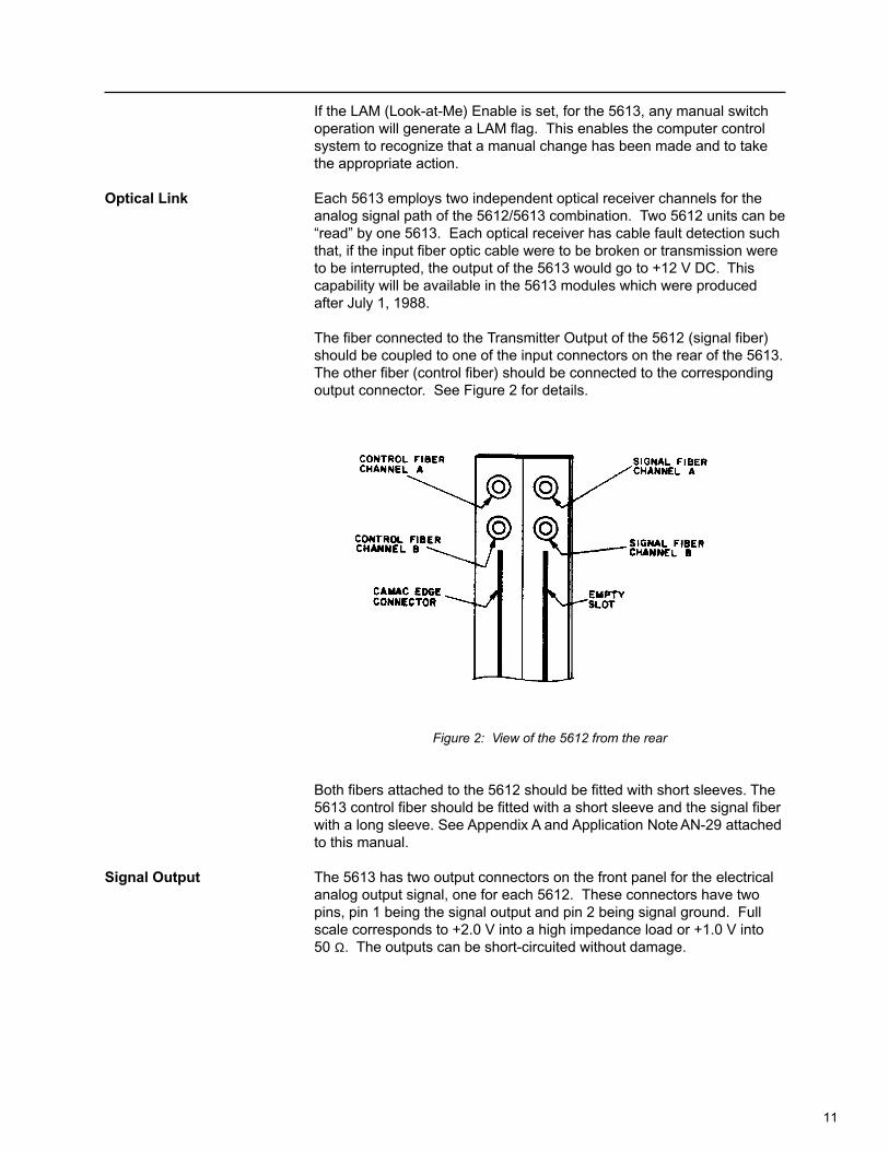
Optical Link Each 5613 employs two independent optical receiver channels for theanalog signal path of the 5612/5613 combination. Two 5612 units can be“read” by one 5613. Each optical receiver has cable fault detection suchthat, if the input fiber optic cable were to be broken or transmission wereto be interrupted, the output of the 5613 would go to +12 V DC. Thiscapability will be available in the 5613 modules which were producedafter July 1, 1988.
The fiber connected to the Transmitter Output of the 5612 (signal fiber)should be coupled to one of the input connectors on the rear of the 5613.The other fiber (control fiber) should be connected to the correspondingoutput connector. See Figure 2 for details.
Figure 2: View of the 5612 from the rear
Both fibers attached to the 5612 should be fitted with short sleeves. The5613 control fiber should be fitted with a short sleeve and the signal fiberwith a long sleeve. See Appendix A and Application Note AN-29 attachedto this manual.
Signal Output The 5613 has two output connectors on the front panel for the electricalanalog output signal, one for each 5612. These connectors have twopins, pin 1 being the signal output and pin 2 being signal ground. Fullscale corresponds to +2.0 V into a high impedance load or +1.0 V into50 Ω. The outputs can be short-circuited without damage.

12
5612 TEST PROCEDURE
Equipment needed 1 - 56121 - 56132 - 100 micron fiber optic cables1 - FG504 Tektronic signal generator1 - DC voltage standard1 - LeCroy 9450 oscilloscope1 - frequency counter1 - volt meter
A) Connect forRemote Operationwith 5613 Std. (1) Adjust 1 V range: Input ±1 V at 100 kHz. Use C17 & C18 to get
desired overshoot to less than 5%.* If ringing or oscillation occurs when changing ranges, adjust C21.
(2) Adjust 100 V range: Input ±100 V at 1 kHz. Use CV1, C9, C10 &C13 to get a flat square wave.
(3) Adjust 10 V range: Input ±10 V at 1 kHz. Use C9 & CV1 to get flatsquare wave.
(4) Recheck 100 V range for proper square wave. *Go back and forthbetween 10 V & 100 V ranges until they are both relatively flat.
(5) Check 100 V range: Input ±100 V at 100 kHz. Check for overshootless than 5%. Use CV1, C9, C10 & C13.
(6) Adjust 50 V range: Input ±50 V at 1 kHz. Check for flat squarewave. Input ±50 V at 100 kHz. Use C19 to adjust overshoot to lessthan 5%.
(7) Adjust 20 V range: Input ±20 V at 1 kHz. Check for flat squarewave. Input ±50 V at 100 kHz. Use C14 to adjust overshoot to lessthan 5%.
(8) Adjust 10 V range: Input ±10 V at 100 kHz. Use C17 & C18 toadjust overshoot to less than 5%. If adjustment is needed, recheckall prior ranges.
(9) Adjust 5 V range: Input ±5 V at 100 kHz. Use C19 to adjustovershoot to less than 5%. If adjustment is needed, recheck 50 Vrange before continuing.
(10) Adjust 2 V range: Input ±2 V at 100 kHz. Use C14 to adjustovershoot less than 5%. If adjustment is needed, recheck 20 Vbefore continuing.
(11) Adjust 1 V range: Input ±1 V at 100 kHz. Check for overshoot lessthan 5%. This should still be correct from step number 1.
(12) Adjust 0.5 V range: Input ±0.5 at 100 kHz. Use C19 to adjustovershoot less than 5%. If adjustment needed, recheck 50 V & 5 Vranges.

13
(13) Adjust 0.2 V range: Input ±0.2 V at 100 kHz. Use C14 to adjustovershoot to less than 5%. If adjustment is needed, recheck 20 V& 2 V ranges.
B) Connect DC VoltageStandard to Input of3512. Switch to LocalMode at Setting #8 (1) With input at 0.0 V, use voltmeter to adjust R33 center pin (wiper)
to 0.0 V ±100 mV.
(2) With input at 0.0 V, use frequency counter connected to TP4,adjust R31 to get 9.000 MHz.
(3) Input 1 V, use R32 to get 8.00 MHz.
(4) Input -1V, check for 10 MHz.
C) Connect a Sinewaveto the Input(Stay in Local Mode) (1) Input ±0.2 V at 100 kHz. Go to local mode setting ‘A’ and check for
3 db drop as you sweep up to 700 kHz minimum (1 MHz maximum).
(2) Input corresponding voltages and check all other ranges as in step#1 with corresponding switch settings.
(3) For increased bandwidth adjust C17 & C18. This will increaseovershoot.
5612 Orientation Drawing (for ECO level 2010 and below)

14
5612 Orientation Drawing (for ECO level 2011 and above)
15
5613 TEST PROCEDURE
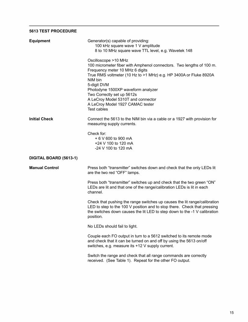
Equipment Generator(s) capable of providing:100 kHz square wave 1 V amplitude8 to 10 MHz square wave TTL level, e.g. Wavetek 148
Oscilloscope >10 MHz100 micrometer fiber with Amphenol connectors. Two lengths of 100 m.Frequency meter 10 MHz 6 digitsTrue RMS voltmeter (10 Hz to >1 MHz) e.g. HP 3400A or Fluke 8920ANIM bin5-digit DVMPhotodyne 1500XP waveform analyzerTwo Correctly set up 5612sA LeCroy Model 5310T and connectorA LeCroy Model 1927 CAMAC testerTest cables
Initial Check Connect the 5613 to the NIM bin via a cable or a 1927 with provision formeasuring supply currents.
Check for:+ 6 V 600 to 900 mA+24 V 100 to 120 mA-24 V 100 to 120 mA
DIGITAL BOARD (5613-1)
Manual Control Press both “transmitter” switches down and check that the only LEDs litare the two red “OFF” lamps.
Press both “transmitter” switches up and check that the two green “ON”LEDs are lit and that one of the range/calibration LEDs is lit in eachchannel.
Check that pushing the range switches up causes the lit range/calibrationLED to step to the 100 V position and to stop there. Check that pressingthe switches down causes the lit LED to step down to the -1 V calibrationposition.
No LEDs should fail to light.
Couple each FO output in turn to a 5612 switched to its remote modeand check that it can be turned on and off by using the 5613 on/offswitches, e.g. measure its +12 V supply current.
Switch the range and check that all range commands are correctlyreceived. (See Table 1). Repeat for the other FO output.

16
decimal value on write lines
0 1 2 3 4 5 6 7 8 9 10 11 12 13 14 15
transmitter setting/mode
100 50 20 n/a 10 5 2 n/a 1 .5 .2 n/a 0.0 BAT +CAL -CAL
hex display value
0 1 2 3 4 5 6 7 8 9 A B C D E F
octal display value
0 1 2 3 4 5 6 7 10 11 12 13 14 15 16 17
Table 1
CAMAC Control Using the LeCroy Model 1927 or a CAMAC test system check thefollowing commands.
CAMAC Commands Result expected at 5613
Z or C Both transmitter OFF LEDs lit. Switchboth channels on manually, 100 Vrange should have been set.
F(16)+A(0)+W Should set range LED of Channel A torange W (see Table 1).
F(0)+A(0)+R R should equal range set on Channel A.
F(16)+A(1)+W Should set range LED of Channel B.
F(0)+A(1)+R R should equal range set on Channel B.
F(24)+A(0) Should set Channel A transmitter OFF.
F(24)+A(1) Should set Channel B transmitter OFF.
F(26)+A(0) Should set Channel A transmitter ON.
F(26)+A(1) Should set Channel B transmitter ON.
F(0)+A(2)+R Bit R1 should indicate status oftransmitter A (1 = ON).Bit R2 should indicate status oftransmitter B (1 = ON).
F(6)+A(0)+R R should read 12755 (octal). (Set theDIL switches on 5613-1 board ifnecessary, see Figure 3.)

17
Figure 3
LAM Tests:
Send Z then F(26)+A(2)Send F(8)+A(0) and verify that no Q returns.
Operate all four panel switches in turn and verify thatthe green ‘L’ LED turns on for each switch. SendF(10)+A(0) after each operation to turn the LED off again.
Verify that F(8)+A(0) returns Q when the ‘L’ LED is lit.
Send F(24)+A(2) and verify that switch operations nolonger light ‘L’.
Send F(8)+A(0) and verify that no Q returns.Send F(10)+A(0).Send F(0)+A(2) and check that Bit R3 and R4 of theresponse are zero. Operate either switch on Channel A.Send F(0)+A(2) and check that Bit R3 is set.Operate either switch on Channel B.Send F(0)+A(2) again and check that Bit R4 is now set.
Send F(0)+A(0) and check that X returns.Send F(1)+A(0) and check for no X.Send F(0)+A(3) and check for no X.
Optical Output Connect 100 m of 100 micrometer fiber to each FO output in turn.Connect its other end to the Photodyne 1500XP and look at the outputwaveform.
Switch each transmitter on and check the output waveform. A mixture ofsine waves should appear.
The peak height should be ~ 20 mW and the minimum should not beclipped.

18
ANALOG BOARD (5613-2)
DC Calibration Connect the input of the 5310T to a pulse generator set to give a TTLlevel square output. Couple the output of the 5310T to one of the opticalinputs on the 5613.
Connect the DVM to Test Point 1 (see Figure 4).Set the generator to give 9.000 MHz +0.001 MHz.Adjust the zero trimmer of the optical receiver to give 0.00 V +0.01 V onthe DVM.Set the generator to 8.000 MHz and adjust the Gain trimmer to give+1.00 V +0.01 V on the DVM.
Figure 4

19
Connect the DVM to the appropriate output socket.Set the generator to 9.000 MHz.Adjust the zero trimmer to give 0.000 +0.001 V on the DVM.Set the generator to 8.000 MHz and adjust the output gain trimmer(VR1) to give 2.000 V. Repeat 9.000 MHz and 8.000 MHz adjustmentsuntil the output reads 0.000 V and 2.000 V.
Repeat the procedure for the other channel.
NOTE: The Test Procedure for the 5613 MOD 100, 200, 201 and 300are the same as a standard 5613, with the exception of the modificationsgain. Therefore, the 8.000 MHz adjustment would be 2.000 V times thegain of the modification.
AC Compensation Apply a 1 V p-p 100 kHz square wave to the input of the 5612.Set the 5612 to range 8, local mode. Couple its output to one of theoptical receiver inputs on the 5613-2 board. Connect the oscilloscope tothe appropriate output connector.Adjust VC1 and VC2 to give a level response with 500 nsec rise time orless, and 3% overshoot. (A slight dip after the peak of the leading edgeseems to be a feature of the optical receiver.)
Check with sinewave (1 V p-p) that -3 dB bandwidth is 700 kHz or more.
Repeat for the second channel.
Output Level Check Apply a +1 V 10 kHz triangular signal to the input of the 5612.Switch the 5612 to range 8.Connect a 50 Ω load to the output of the 5613.Check that the output shows +1.00 V.Increase the input until clipping occurs.The output should be at least +1.25 V before this happens.
System Noise Check Couple 5612 outputs to the FO inputs of the 5613 and turn the 5612 on.Connect the output of channel A to the true rms voltmeter with a50 Ω input impedance.
Switch the rms voltmeter to 5 mV and read the noise voltage. If lessthan 2.5 mV, the unit is acceptable (2.5 mV rms noise corresponds to arms signal to rms noise ratio of 283 (=49 dB).
Proceed with channel B.
5613 MOD 100 The 5613 MOD 100 differs from the standard 5613 in the following:
1. System gain is 1.25 times higher; and
2. Maximum output voltage swing is 1.25 times higher than for thestandard 5613.
For example, if the user applies a 1 V signal to the 5612 and selects the1 V range, the standard 5613 will output a 1 V signal whereas the5613 MOD 100 will output 1.25 V.
20
To convert a standard 5613 into a 5613 MOD the setting of the gainadjustment trim resistor R8 (located near the output amplifier) must bechanged to give 25% more gain (one trim resistor for each channel).
To convert a 5613 MOD 100 into a standard 5613 the setting of the gainadjustment trim resistor R8 must be lowered to give 25% lower gain.
Whenever the gain setting is changed the link should be checked forcorrect pulse and frequency response. If necessary, a correction of anymisadjustment can be made by adjusting the frequency response trimcapacitors C4 and C11 (1 pair for each channel).
5613 MOD 201 The 5613 MOD 201 employs a modified receiver module to allow amaximum signal swing of + V (20 mA) into high impedance (>250 Ω).This option allows the 5613 to be used with the 8210 transient recordermodules.
Note that with this modification the 5612/5613 MOD 201 combinationnow has a gain of 5. An example of this would be if the user applied a+1 V signal to the input of the 5612 and set the 5613 to the +1 V range,the output of the 5613 would be +5 V.
The 5613 MOD 201 has cable fault detection whereas, if the input fiberoptic cable were to be broken or transmission were to be interrupted, theoutput of the 5613 MOD 201 would go to +12 V DC. This capability willbe available in 5613 modules which were produced after July 1, 1988.
5613 MOD 300 The 5613 MOD 300 employs a modified receiver module to allow amaximum signal swing of +10 V (10 mA) into high impedance (>1K Ω).The 5613 MOD 300 has cable fault detection capabilities. Whereas, ifthe input fiber optic cable were to be broken or transmission were to beinterrupted, the output of the 5613 MOD 300 would go to +12 V DC. Thiscapability will be available in 5613 modules which were produced afterJuly 1, 1988.
Note that with this modification the 5612/5613 MOD 300 combinationnow has a gain of 10. An example of this would be if the user applied a+1 V signal to the input of the 5612 and set the 5613 to the +1 V range,the output of the 5613 would be +10 V.
MATING OF FIBEROPTIC CABLES The mating end of an Amphenol 906 connector has a smaller diameter
than the body of the connector. This is intended to locate the plasticsleeve which is used to align the connector with the mating part.
When two fibers are connected using two 906 connectors and a match-ing barrel connector, a single long sleeve must be used. When theconnection is unmated, the sleeve may remain attached to either of themated connectors. When reconnecting the fiber, care must be taken toensure that the two connectors share one and only one sleeve. Since itis difficult to tell if the connector inside the barrel has retained a sleevethe safest procedure is to fit a sleeve to the free connector and attemptto mate it. If it fits, all is well. If it fails to mate there is a sleeve already in

21
the barrel, and the one on the free connector should be removed bygripping it firmly with the fingers and twisting it off. Nearly all LeCroyfiber optic transmitters use LED’s fitted with pigtails and hence the outputconnector is of this double-ended barrel type and uses the long sleeve.
When the end of a fiber is coupled directly into a detector diode or to asurface emitting LED the incoming fiber is aligned by a short plasticsleeve which covers the tip of the 906 connector but does not extendbeyond it. This sleeve may remain within the panel connector when thefree connector is unmated. If a second sleeve is then fitted to theconnector and the connector screwed in considerable damage can bedone to the detector diode. Care should always be taken to ensure thatonly one sleeve is being used; 906 connectors can be used without thissleeve but poorer optical coupling will result.
The Amphenol 905 series connectors do not use plastic sleeves foralignment but are only intended for use with 200 micrometer fiber.

22

23
INDEX
5612 Test Procedure 65612 Transmitter 35613 Reciever/Link Controller 45613 Test Procedure 9
B
Battery Charger 3
C
CAMAC Commands 4Control Fiber 5Control Mode 3Control Modes 4Customer Service 1
I
Input 4Input Connector 4Input Impedance 4Input Ranges 4Internal Battery 3
L
LAM Flag 5LED Displays 4Local Mode 3
M
Maintenance Agreements 1
O
Optical Fiber 4Optical Link 4
P
Power 3, 4Product Assistance 1
R
Remote Mode 3
S
Service Procedure 2Signal Fiber 5Signal Output 5Software Licensing Agreement 2
T
Three-Position Slide Switch 3
W
Warranty 1

24