dc motor speed control using fuzzy logic...
TRANSCRIPT
DC MOTOR SPEED CONTROL USING FUZZY LOGIC CONTROLLER
SHAHRIZAL BIN SAAT
A thesis submitted in
fulfillment of the requirement for the award of the
Master of Electrical Engineering
Faculty of Electrical and Electronic Engineering
Universiti Tun Hussein Onn Malaysia
JANUARY 2014
v
ABSTRACT
Fuzzy Logic Controller has gained wide popularity in the application of speed
control for the DC motors. Their performance, with the auto tuning is desirable. In
this project, the performance of a selected DC motor controlled by a Proportional
Integral Derivative (PID) controller and Fuzzy Logic Controller are investigated. An
overshoot speed is observed with an accompanied settling time thereby confirming
the behavior of a PID controller and Fuzzy Logic Controller. It is therefore a matter
of necessity to tune the Fuzzy Logic Controller in order to obtain the desired
performance. On the other hand, a Fuzzy Logic Controller applied to the DC motor is
investigated. With the application of appropriate expert rules, there is minimum
overshoot and the settling time is within the desired value. With the Fuzzy Logic
Controller, manual tuning is eliminated and intelligent tuning takes the centre stage
with satisfactory performance. The speed control of the DC motor is performed using
PID and FLC in MATLAB environment. The results show that the FLC approach
has minimum overshoot, minimum transient and steady state error, which show more
effectiveness and efficiency of FLC than conventional PID controller.
vi
ABSTRAK
Pengawal Logik Kabur (FLC) telah digunakan secara meluas di dalam applikasi
untuk mengawal kelajuan motor arus terus. Prestasinya dengan kebolehan untuk
mengawal secara automatik adalah diperlukan. Di dalam projek ini, prestasi motor
arus terus yang dipilih telah dikawal dengan menggunakan pengawal Proportional
Integral Derivative (PID) dan Pengawal Logik Kabur (FLC) telah dikaji. Untuk
tujuan itu, nilai lajakan kelajuan maksimum untuk mencapai nilai kelajuan yang telah
ditetapkan dan juga masa yang diambil untuk mencapai nilai sasaran kelajuan yang
stabil telah dikenal pasti dan dianalisis untuk mengesahkan kelakuan pengawal
Proportional Integral Derivative (PID) dan juga Pengawal Logik Kabur (FLC).
Dengan itu, pelarasan hendaklah di lakukan keatas Pengawal Logik Kabur (FLC)
untuk memastikan prestasi yang dihasilkan adalah seperti yang dikehendaki. Dengan
kata lain, perkara berkaitan dengan kelakuan Pengawal Logik Kabur (FLC) telah
dikaji. Dengan menggunakan nilai yang sesuai, nilai lajakan kelajuan maksimum dan
juga masa yang diperlukan untuk mencapai keadaan kelajuan stabil telah dapat
dikurangkan. Dengan menggunakan Pengawal Logik Kabur (FLC), pelarasan secara
manual telah di hapuskan dan pelarasan secara automatik telah mengambil tempat
untuk memberikan prestasi seperti yang dikehendaki. Kawalan kelajuan motor arus
terus yang dilakukan dengan menggunakan pengawal PID dan pengawal FLC adalah
dengan menggunakan perisian MATLAB. Keputusannya menunjukkan bahawa
dengan menggunakan Pengawal Logik Kabur, nilai lajakan kelajuan maksimum
adalah minimum, gelombang peralihan yang minimum dan juga nilai ralat dalam
keadaan kelajuan stabil yang minimum telah dapat dicapai berbanding daripada
dengan menggunakan pengawal konvensional Proportional Integral Derivative
(PID).
vii
CONTENTS
TITLE i
DECLARATION ii
DEDICATION iii
ACKNOWLEDGEMENT iv
ABSTRACT v
CONTENTS vii
LIST OF TABLES x
LIST OF FIGURES xii
LIST OF SYMBOLS AND ABBREVIATIONS xv
CHAPTER 1 INTRODUCTION 1
1.1 Project Background 1
1.2 Problem Statements 2
1.3 Project Objectives 3
1.4 Project Scopes 3
CHAPTER 2 LITERATURE REVIEW 4
2.1 Introduction 4
2.2 Fuzzy Logic Controller 4
2.2.1 Fuzzy Input 5
2.2.2 Fuzzification 6
2.2.3 Knowledge Based / Rule Based 6
2.2.4 Fuzzy Logical 6
2.2.5 Defuzzification 6
2.2.6 Fuzzy Output 7
2.3 PID Controller 7
2.3.1 Proportional Gain (KP) 8
viii
2.3.2 Integral Gain (KI) 9
2.3.3 Derivative Gain (KD) 9
2.4 Introduction to Electrical Motor 9
2.5 Type of DC Motor 9
2.5.1 Brushed DC Motor 9
2.5.2 Synchronous DC Motor 10
2.5.2.1 Brushless DC Motor 10
2.5.2.2 Stepper Motor 11
2.6 Speed Control Method of DC Motor 12
2.6.1 Field Resistance Control Method 12
2.6.2 Armature Voltage Control Method 12
2.6.3 Armature Resistance Control Method 12
2.7 Pulse Width Modulation (PWM) 13
CHAPTER 3 METHODOLOGY 14
3.1 Chapter Overview 14
3.2 Research Methodology 15
3.3 DC Motor Modelling 16
3.3.1 DC Motor System Equation 16
3.4 Open Loop Modelling System 18
3.5 PID Controller Modelling System 20
3.5.1 PID Controller Design 21
3.6 Fuzzy Logic Controller Modelling System 22
3.7 Fuzzy Logic Controller Design 22
3.7.1 Fuzzy Logic Controller (7x3) 23
3.7.2 Fuzzy Logic Controller (5x5) 30
3.7.3 Fuzzy Logic Controller (7x7) 36
3.8 Comparison PID and FLC Modelling System 41
ix
CHAPTER 4 RESULT AND ANALYSIS 43
4.1 Introduction 43
4.2 Closed Loop System with PID Controller 45
4.3 Closed Loop System with FLC Controller (7x3) 49
4.4 Closed Loop System with FLC Controller (5x5) 53
4.5 Closed Loop System with Flc Controller (7x7) 57
4.6 Closed Loop System Comparison Between PID and FLC 62
4.7 Defuzzification Output Verification 65
4.7.1 FLC (7x7) Defuzzification Output Verification 1 67
4.7.2 FLC (7x7) Defuzzification Output Verification 2 69
4.7.3 FLC (7x7) Defuzzification Output Verification 3 71
4.7.4 FLC (7x7) Defuzzification Output Verification 4 73
4.7.5 FLC (7x7) Defuzzification Output Verification 5 75
4.7.6 FLC (7x7) Defuzzification Output Verification 6 77
CHAPTER 5 CONCLUSIONS AND FUTURE WORKS 79
5.1 Conclusion 79
5.2 Future Works 79
REFERENCES 81
x
LIST OF TABLE
Table 3-1 : Open loop test for DC motor block diagram 19
Table 3-2 : FLC controller (7x3) error input membership function 24
Table 3-3 : FLC controller (7x3) change of error input membership function 25
Table 3-4 : FLC controller (7x3) control output membership function 26
Table 3-5 : FLC controller (5x5) error input membership function 32
Table 3-6 : FLC controller (5x5) change of error input membership function 32
Table 3-7 : FLC controller (5x5) control output membership function 33
Table 3-8 : FLC controller (7x7) error input membership function 37
Table 3-9 : FLC controller (7x7) change of error input membership function 38
Table 3-10 : FLC controller (7x7) control output membership function 39
Table 4-1 : Parameter obtain at speed rated 60 rpm with PID controller 46
Table 4-2 : Parameter obtain at speed rated 70 rpm with PID controller 47
Table 4-3 : Parameter obtain at speed rated 80 rpm with PID controller 48
Table 4-4 : Comparison data for PID controller 49
Table 4-5 : Design rules of FLC controller (7x3) 50
Table 4-6 : Parameter obtain at speed rated 60 rpm with FLC (7x3) 51
Table 4-7 : Parameter obtain at speed rated 60 rpm with FLC (7x3) 52
Table 4-8 : Parameter obtain at speed rated 60 rpm with FLC (7x3) 53
Table 4-9 : Comparison data for FLC (7x3) 53
Table 4-10 : Design rules of FLC (5x5) 54
Table 4-11 : Parameter obtain at speed rated 60 rpm with FLC (5x5) 54
Table 4-12 : Parameter obtain at speed rated 60 rpm with FLC (5x5) 55
Table 4-13 : Parameter obtain at speed rated 60 rpm with FLC (5x5) 56
Table 4-14 : Comparison data for FLC (5x5) 57
Table 4-15 : Design rules of FLC (7x7) 57
Table 4-16 : Parameter obtain at speed rated 60 rpm with FLC (7x7) 58
Table 4-17 : Parameter obtain at speed rated 60 rpm with FLC (7x7) 59
Table 4-18 : Parameter obtain at speed rated 60 rpm with FLC (7x7) 60
xi
Table 4-19 : Comparison data for FLC (7x7) 61
Table 4-20 : Performance of FLC (7x3), FLC (5x5) and FLC (7x7) 61
Table 4-21 : Speed rated at 60 rpm with PID and FLC (7x7) 63
Table 4-22 : Speed rated at 70 rpm with PID and FLC (7x7) 64
Table 4-23 : Speed rated at 80 rpm with PID and FLC (7x7) 65
Table 4-24 : FLC (7x7) defuzzification output data for verification 1 67
Table 4-25 : FLC (7x7) defuzzification output data for verification 2 69
Table 4-26 : FLC (7x7) defuzzification output data for verification 3 71
Table 4-27 : FLC (7x7) defuzzification output data for verification 4 73
Table 4-28 : FLC (7x7) defuzzification output data for verification 5 75
Table 4-29 : FLC (7x7) defuzzification output data for verification 6 77
xii
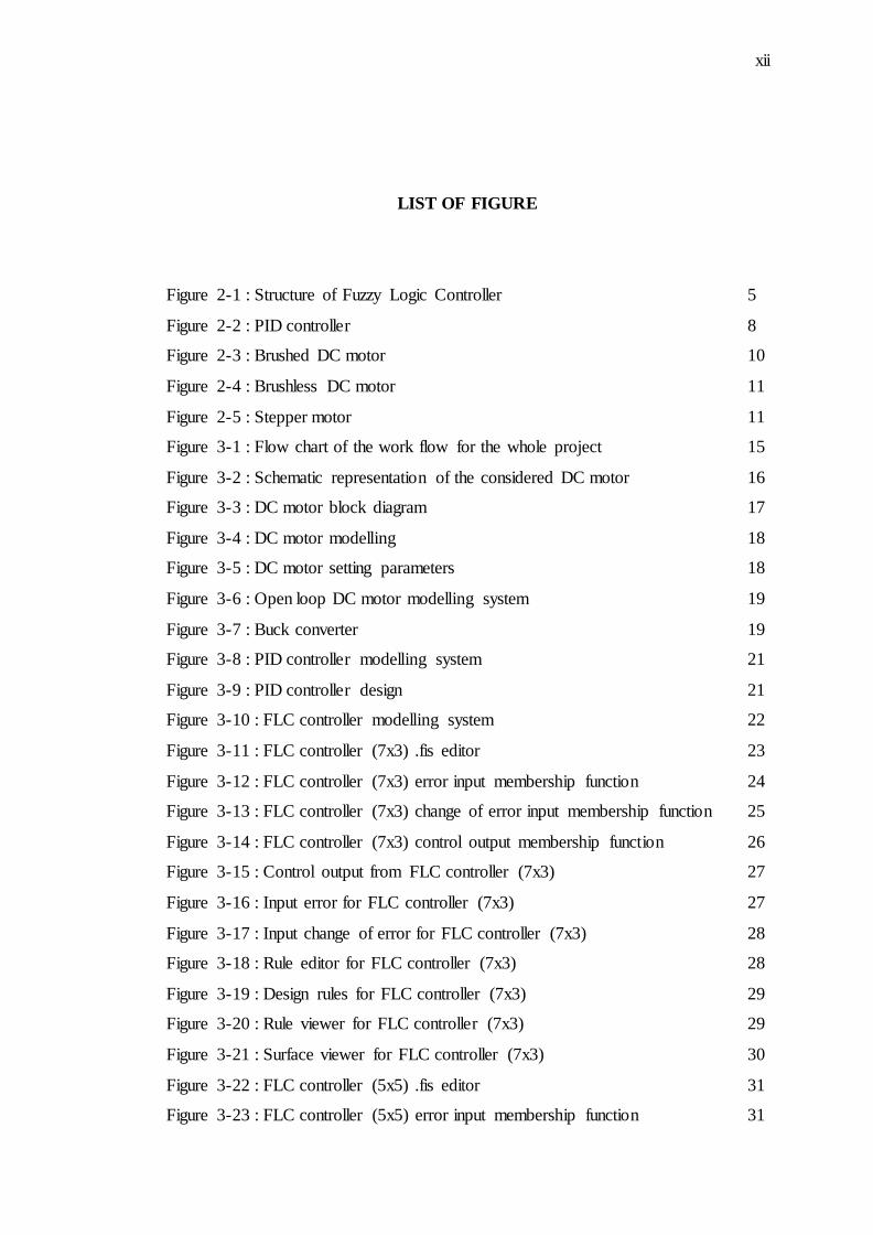
LIST OF FIGURE
Figure 2-1 : Structure of Fuzzy Logic Controller 5
Figure 2-2 : PID controller 8
Figure 2-3 : Brushed DC motor 10
Figure 2-4 : Brushless DC motor 11
Figure 2-5 : Stepper motor 11
Figure 3-1 : Flow chart of the work flow for the whole project 15
Figure 3-2 : Schematic representation of the considered DC motor 16
Figure 3-3 : DC motor block diagram 17
Figure 3-4 : DC motor modelling 18
Figure 3-5 : DC motor setting parameters 18
Figure 3-6 : Open loop DC motor modelling system 19
Figure 3-7 : Buck converter 19
Figure 3-8 : PID controller modelling system 21
Figure 3-9 : PID controller design 21
Figure 3-10 : FLC controller modelling system 22
Figure 3-11 : FLC controller (7x3) .fis editor 23
Figure 3-12 : FLC controller (7x3) error input membership function 24
Figure 3-13 : FLC controller (7x3) change of error input membership function 25
Figure 3-14 : FLC controller (7x3) control output membership function 26
Figure 3-15 : Control output from FLC controller (7x3) 27
Figure 3-16 : Input error for FLC controller (7x3) 27
Figure 3-17 : Input change of error for FLC controller (7x3) 28
Figure 3-18 : Rule editor for FLC controller (7x3) 28
Figure 3-19 : Design rules for FLC controller (7x3) 29
Figure 3-20 : Rule viewer for FLC controller (7x3) 29
Figure 3-21 : Surface viewer for FLC controller (7x3) 30
Figure 3-22 : FLC controller (5x5) .fis editor 31
Figure 3-23 : FLC controller (5x5) error input membership function 31
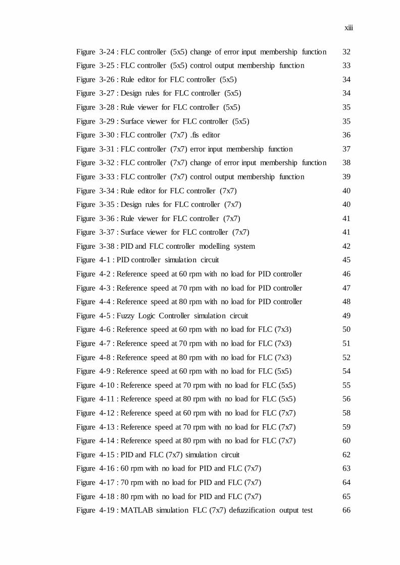
xiii
Figure 3-24 : FLC controller (5x5) change of error input membership function 32
Figure 3-25 : FLC controller (5x5) control output membership function 33
Figure 3-26 : Rule editor for FLC controller (5x5) 34
Figure 3-27 : Design rules for FLC controller (5x5) 34
Figure 3-28 : Rule viewer for FLC controller (5x5) 35
Figure 3-29 : Surface viewer for FLC controller (5x5) 35
Figure 3-30 : FLC controller (7x7) .fis editor 36
Figure 3-31 : FLC controller (7x7) error input membership function 37
Figure 3-32 : FLC controller (7x7) change of error input membership function 38
Figure 3-33 : FLC controller (7x7) control output membership function 39
Figure 3-34 : Rule editor for FLC controller (7x7) 40
Figure 3-35 : Design rules for FLC controller (7x7) 40
Figure 3-36 : Rule viewer for FLC controller (7x7) 41
Figure 3-37 : Surface viewer for FLC controller (7x7) 41
Figure 3-38 : PID and FLC controller modelling system 42
Figure 4-1 : PID controller simulation circuit 45
Figure 4-2 : Reference speed at 60 rpm with no load for PID controller 46
Figure 4-3 : Reference speed at 70 rpm with no load for PID controller 47
Figure 4-4 : Reference speed at 80 rpm with no load for PID controller 48
Figure 4-5 : Fuzzy Logic Controller simulation circuit 49
Figure 4-6 : Reference speed at 60 rpm with no load for FLC (7x3) 50
Figure 4-7 : Reference speed at 70 rpm with no load for FLC (7x3) 51
Figure 4-8 : Reference speed at 80 rpm with no load for FLC (7x3) 52
Figure 4-9 : Reference speed at 60 rpm with no load for FLC (5x5) 54
Figure 4-10 : Reference speed at 70 rpm with no load for FLC (5x5) 55
Figure 4-11 : Reference speed at 80 rpm with no load for FLC (5x5) 56
Figure 4-12 : Reference speed at 60 rpm with no load for FLC (7x7) 58
Figure 4-13 : Reference speed at 70 rpm with no load for FLC (7x7) 59
Figure 4-14 : Reference speed at 80 rpm with no load for FLC (7x7) 60
Figure 4-15 : PID and FLC (7x7) simulation circuit 62
Figure 4-16 : 60 rpm with no load for PID and FLC (7x7) 63
Figure 4-17 : 70 rpm with no load for PID and FLC (7x7) 64
Figure 4-18 : 80 rpm with no load for PID and FLC (7x7) 65
Figure 4-19 : MATLAB simulation FLC (7x7) defuzzification output test 66
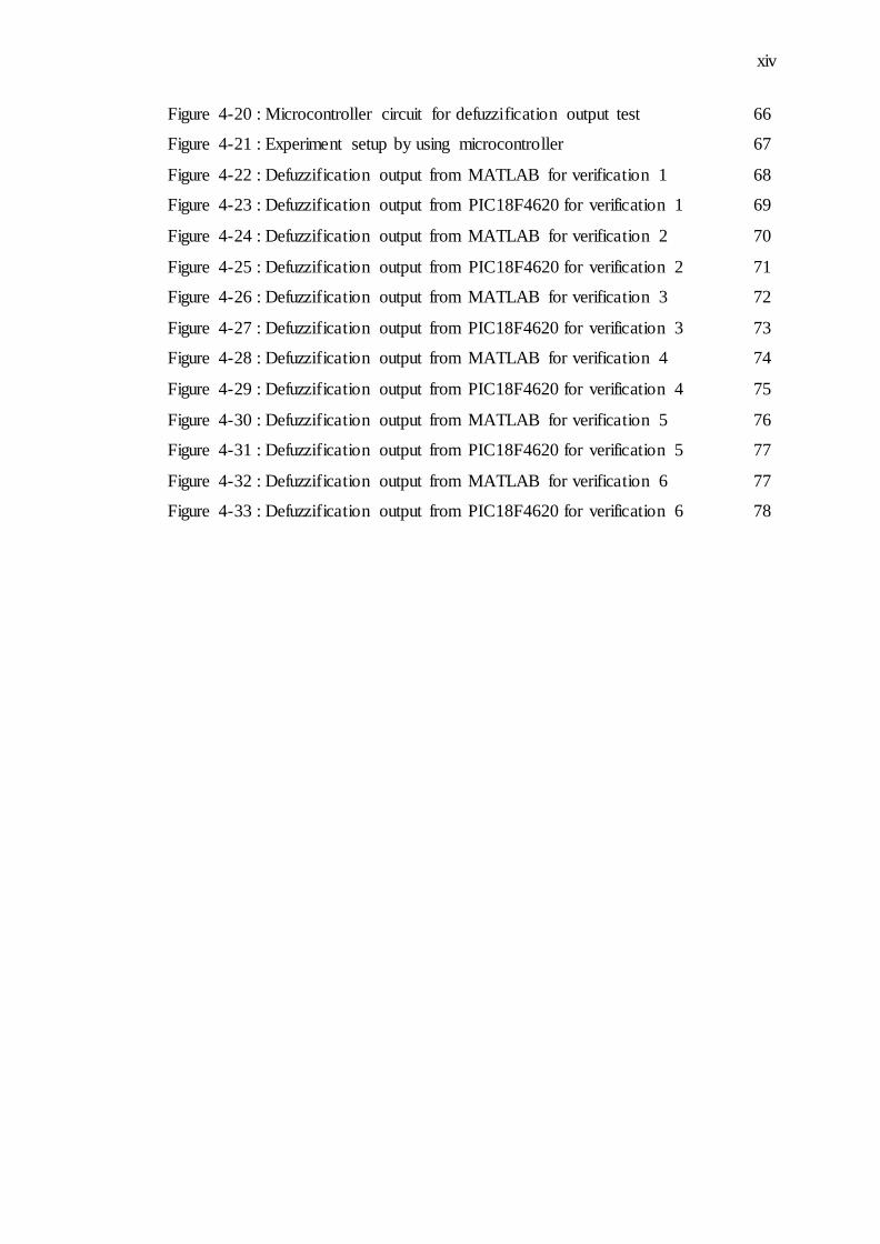
xiv
Figure 4-20 : Microcontroller circuit for defuzzification output test 66
Figure 4-21 : Experiment setup by using microcontroller 67
Figure 4-22 : Defuzzification output from MATLAB for verification 1 68
Figure 4-23 : Defuzzification output from PIC18F4620 for verification 1 69
Figure 4-24 : Defuzzification output from MATLAB for verification 2 70
Figure 4-25 : Defuzzification output from PIC18F4620 for verification 2 71
Figure 4-26 : Defuzzification output from MATLAB for verification 3 72
Figure 4-27 : Defuzzification output from PIC18F4620 for verification 3 73
Figure 4-28 : Defuzzification output from MATLAB for verification 4 74
Figure 4-29 : Defuzzification output from PIC18F4620 for verification 4 75
Figure 4-30 : Defuzzification output from MATLAB for verification 5 76
Figure 4-31 : Defuzzification output from PIC18F4620 for verification 5 77
Figure 4-32 : Defuzzification output from MATLAB for verification 6 77
Figure 4-33 : Defuzzification output from PIC18F4620 for verification 6 78
xv
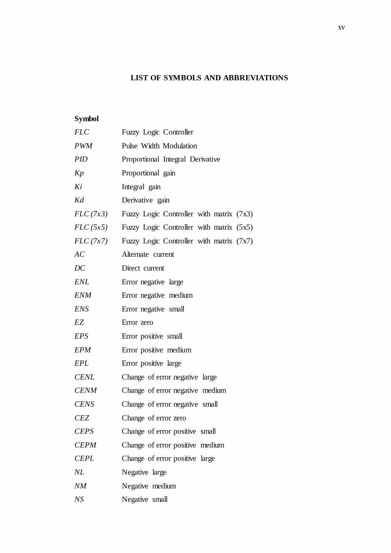
LIST OF SYMBOLS AND ABBREVIATIONS
Symbol
FLC Fuzzy Logic Controller
PWM Pulse Width Modulation
PID Proportional Integral Derivative
Kp Proportional gain
Ki Integral gain
Kd Derivative gain
FLC (7x3) Fuzzy Logic Controller with matrix (7x3)
FLC (5x5) Fuzzy Logic Controller with matrix (5x5)
FLC (7x7) Fuzzy Logic Controller with matrix (7x7)
AC Alternate current
DC Direct current
ENL Error negative large
ENM Error negative medium
ENS Error negative small
EZ Error zero
EPS Error positive small
EPM Error positive medium
EPL Error positive large
CENL Change of error negative large
CENM Change of error negative medium
CENS Change of error negative small
CEZ Change of error zero
CEPS Change of error positive small
CEPM Change of error positive medium
CEPL Change of error positive large
NL Negative large
NM Negative medium
NS Negative small
xvi
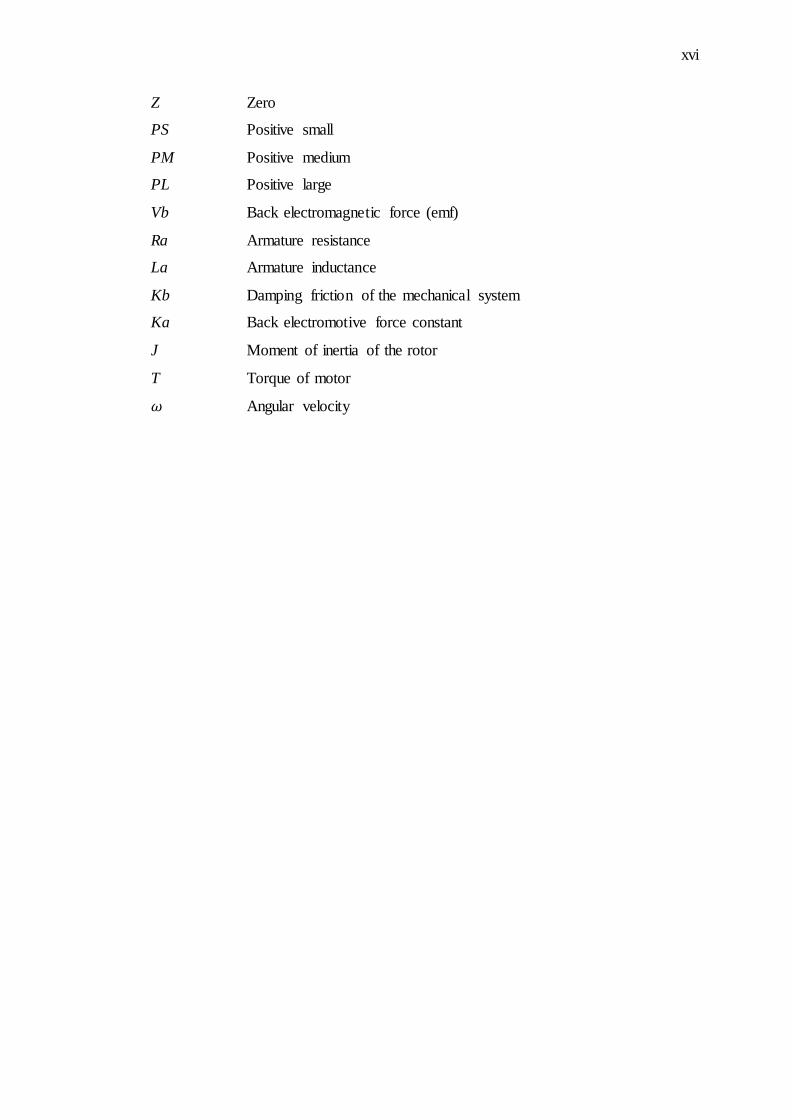
Z Zero
PS Positive small
PM Positive medium
PL Positive large
Vb Back electromagnetic force (emf)
Ra Armature resistance
La Armature inductance
Kb Damping friction of the mechanical system
Ka Back electromotive force constant
J Moment of inertia of the rotor
T Torque of motor
Angular velocity
CHAPTER 1
INTRODUCTION
1.1 Project Background
The speed of DC motors can be adjusted within wide boundaries so that this provides
easy controllability and high performance. DC motors used in many applications
such as still rolling mills, electric trains, electric vehicles, electric cranes and robotic
manipulators require speed controller to perform their tasks. Speed controller of DC
motors is carried out by means of voltage control in 1981 firstly by Ward Leonard
[1]. The regulated voltage sources used for DC motor speed control have gained
more importance after the introduction of thyristor as switching devices in power
elctronics. Then semiconductor components such as MOSFET, IGBT, and GTO have
been used as electric switching devices [2].
DC motor systems are indispensable in modern industries. DC motors are
used in a variety of applications in industrial electronics and robotics that includes
precision positioning as well as speed control. DC motors use feedback controller to
control the speed or the position, or both. Today most famous and most frequently
used type of controller in industry is PID controller [3], but PID controllers don’t
offer satisfactory results when adaptive algorithm are required [4,5].
Fuzzy Logic Controller offers some solutions. Basic advantages of Fuzzy
Logic Controller is that it does not require knowing complete mathematical model of
system [6,7,8,9]. Popularity of FLC is explained with fact that it puts clear and
simple implementation of human thinking into controlling algorithm [10]. Fuzzy
2
controllers are robust regarding dynamic changes and have wide stability range [11].
FLC only based on approximate and linguistic information [6,7,12].
The basic continuous feedback controller is PID controller which possesses
good performance. However is adaptive enough only with flexible tuning. Although
many advanced control techniques such as self-tuning control, model reference
adaptive control, sliding mode control and fuzzy logic control have been proposed to
improve system performances. In this project, Fuzzy Logic Controller has been
proposed for improvement and analysis of the system performance.
1.2 Problem Statements
The nonlinear characteristics of a DC motor such as saturation and friction could
degrade the performance of conventional controllers. Many advanced model based
control methods such as variable structure control and model reference adaptive
control have been developed to reduce these effects. However, the performance of
these methods depends on the accuracy of the system models and parameters.
Generally, an accurate non-linear model of an actual DC motor is difficult to find,
and parameter values obtained from system identification may be only approximated
values [6,7].
Control system that could be able to give a fast response in order to maintain
the speed of the DC motor at the desired value with a minimum overshoot, minimum
steady state error, minimum settling time and fast rising time are very important and
crucial in industrial application.
Conventional control has proven for a long time to be good enough to handle
control tasks on system control, however this implementation relies on an exact
mathematical model of the plan to be control and not a simple mathematical
operations. The fuzzy logic control, unlike conventional control system, is able to
model inaccurate or imprecise models. The fuzzy logic approach offers a simpler,
quicker and more reliable solution that is clear advantages over conventional
techniques [10,12].
3
1.3 Project Objectives
The objectives of this project are as follows:
i) To design a fuzzy logic controller as another type of controller that can be
used on to control speed of the DC motor.
ii) To analyze the performance comparison between PID and Fuzzy Logic
Controller in order to control speed of the DC motor by simulation.
iii) To evaluate and validate performance of the design FLC defuzzification
output by using microcontroller.
1.4 Project Scopes
The scope of the project including of the following:
i) Validate performance of the PID and Fuzzy Logic Controller by simulation.
ii) The fine tuning for the each type of controller to optimize the result.
iii) FLC hardware implementation using microcontroller for an open loop test for
defuzzification output evaluation and validation.
CHAPTER 2
LITERATURE REVIEW
2.1 Introduction
The concept of fuzzy logic was introduced by Lotfi Zadeh [13], as a formal
methodology to represent heuristic knowledge [14]. Based on fuzzy logic, easily
comprehensive rules can be used to implement controller for complex systems [14].
Fuzzy logic controller systems are a practical alternative for the development of a
wide variety of control application, being able to control nonlinear systems using
heuristic information supplied intuitively by the programmer. Beyond their more
intuitive design, fuzzy controllers have robustness and low cost inherent
characteristics [13]. FLC system can be implemented in hardware in several ways
such as microprocessors or microcontrollers, but there are digital signal processor
based implementations as well [15].
2.2 Fuzzy Logic Controller
Fuzzy Logic is a form of logical reasoning that can be incorporated into automation
systems typically human reasoning schemes. Fuzzy theory was first proposed and
investigated by Prof Zadeh in 1965 [16]. One of the main features of fuzzy logic is
its ability to operate with vague or ambiguous concepts typical of qualitative
reasoning, based on a mathematical support quantitative conclusion can be drawn
from a set of observations and qualitative rules. Fuzzy logic control is the application
of fuzzy inference process automation. A typical fuzzy controller infers the
5
consequent of more or less large simple rules, this process of reasoning can be
performed in parallel, yielding the result with a simple logical sum. This parallel
processing capability allows even relatively complex controllers to perform the fuzzy
inference in a minimum computation time.
In a fuzzy logic system, the inference mechanism decides what rules to apply
for the corresponding inputs by matching the fuzzified inputs to the premises of the
rules in the rule base. The inference mechanism provides a fuzzy set that indicates
the certainty that the plant input should take the various values. The defuzzification
is used to convert the fuzzy set produced by the inference mechanism into a crisp
output to be used by the plant [20].
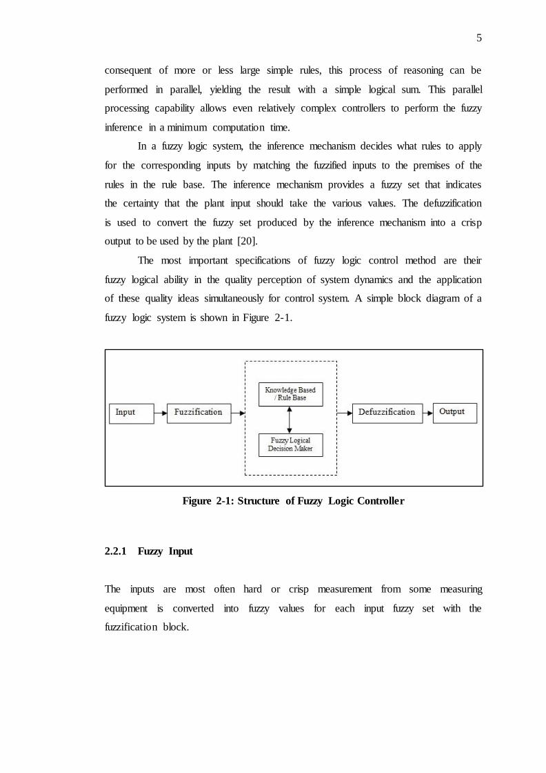
The most important specifications of fuzzy logic control method are their
fuzzy logical ability in the quality perception of system dynamics and the application
of these quality ideas simultaneously for control system. A simple block diagram of a
fuzzy logic system is shown in Figure 2-1.
Figure 2-1: Structure of Fuzzy Logic Controller
2.2.1 Fuzzy Input
The inputs are most often hard or crisp measurement from some measuring
equipment is converted into fuzzy values for each input fuzzy set with the
fuzzification block.
6
2.2.2 Fuzzification
The fuzzification block performs the following tasks:
i) Measures the value of input variables.
ii) Performs a scale mapping that transfers the range of values of input variables
into the corresponding universes of discourse.
iii) Performs the function of fuzzification, which converts input data into suitable
linguistic values that may be viewed as labels of fuzzy sets.
2.2.3 Knowledge Based / Rule Based
The collection of rules is called a rule base. The rules are in “If Then” format and
formally the If side is called the conditions and the Then side is called the
conclusion. The computer is able to execute the rules and compute a control signal
depending on the measured inputs error (e) and change in error (ce). In a rule based
controller the control strategy is stored in a more or less natural language. A rule
base controller is easy to understand and easy to maintain for a non-specialist end
user and an equivalent controller could be implemented using conventional
techniques.
2.2.4 Fuzzy Logical
The fuzzy engine is the kernel of a fuzzy logic controller, which has capability of
simulating human decision making based on fuzzy concepts and of inferring fuzzy
control actions using fuzzy implication (fuzzy relation) and the rules of inference in
fuzzy logic. This means that the fuzzy inference engine handles rule inference where
human experience can easily be injected through linguistic rules.
2.2.5 Defuzzification
Defuzzification is when all the actions that have been activated are combined and
converted into a single non-fuzzy output signal which is the control signal of the
system. The output levels are depending on the rules that the systems have and the
positions depending on the non-linearities existing to the systems. To achieve the
result, develop the control curve of the system representing the I/O relation of the
7
systems and based on the information, define the output degree of the membership
function with the aim to minimize the effect of the non-linearity.
2.2.6 Fuzzy Output
The output is output gain that can be tuned and also become as an integrator. The
output crisp value can be calculated by the centre of gravity or the weighted average.
2.3 PID Controller
Although the modern control technique have taken considerable attention during the
last several years, PID controllers are still one of the best known controllers used in
many industrial processes. Their important and impressive properties such as fast and
efficient control action, simple but functional structure, ease of application and
robust performance are among the reasons for their preferences [17,18].
During the design phase of a PID controllers, there is a crucial and
challenging task, in that, three controller parameter Kp, Ki and Kd which have a
significant controller success, should be determined properly. Practically, this
determination or say ‘tuning process’ is performed by an experienced operator based
on trial and error method through the some practical rules. It is apparent that this
method is time consuming and accordingly needs for relatively more time. Besides,
once tuned, the controller performance may later deteriorate because of nonlinear or
time varying characteristics of the process under control [19]. In others word, a PID
controller with fixed parameter set cannot provide a moderate performance over wide
a range of operating condition.
A proportional- integral- derivative controller (PID Controller) widely used in
industrial control system. A PID controller attempts to correct the error between a
measured process variable and a desired set point. The response of PID controller
and Fuzzy Logic controller will be compared on the chapter four.
8
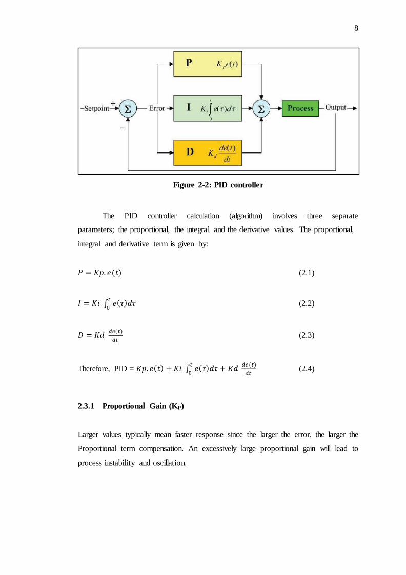
Figure 2-2: PID controller
The PID controller calculation (algorithm) involves three separate
parameters; the proportional, the integral and the derivative values. The proportional,
integral and derivative term is given by:
(2.1)
∫
(2.2)
(2.3)
Therefore, PID = ∫
(2.4)
2.3.1 Proportional Gain (KP)
Larger values typically mean faster response since the larger the error, the larger the
Proportional term compensation. An excessively large proportional gain will lead to
process instability and oscillation.
9
2.3.2 Integral Gain (KI)
Larger values imply steady state errors are eliminated more quickly. The trade-off is
larger overshoot: any negative error integrated during transient response must be
integrated away by positive error before we reach steady state.
2.3.3 Derivative Gain (KD)
Larger values decrease overshoot, but slows down transient response and may lead to
instability due to signal noise amplification in the differentiation of the error.
2.4 Introduction to Electrical Motor
There are two main types of electrical motors. There are direct current or DC and
alternating current or AC motors. The reference of DC or AC refers to how the
electrical current is transferred through and from the motor. Both types of motors
have different functions and uses. DC motors come in two general types. They can
have brushes or be brushless (synchronous motor). Then, AC motors come in two
different types which are they can be single phase and three phases. This project will
cover and design the controller for a DC motor only, the next subtopic will be
discussed details on types on DC motor.
2.5 Type of DC Motor
There are several types of DC motor that commonly used in the industry such as
brushed DC motor and the synchronous DC motor. This subtopic will elaborate
detailed for each type of DC motors.
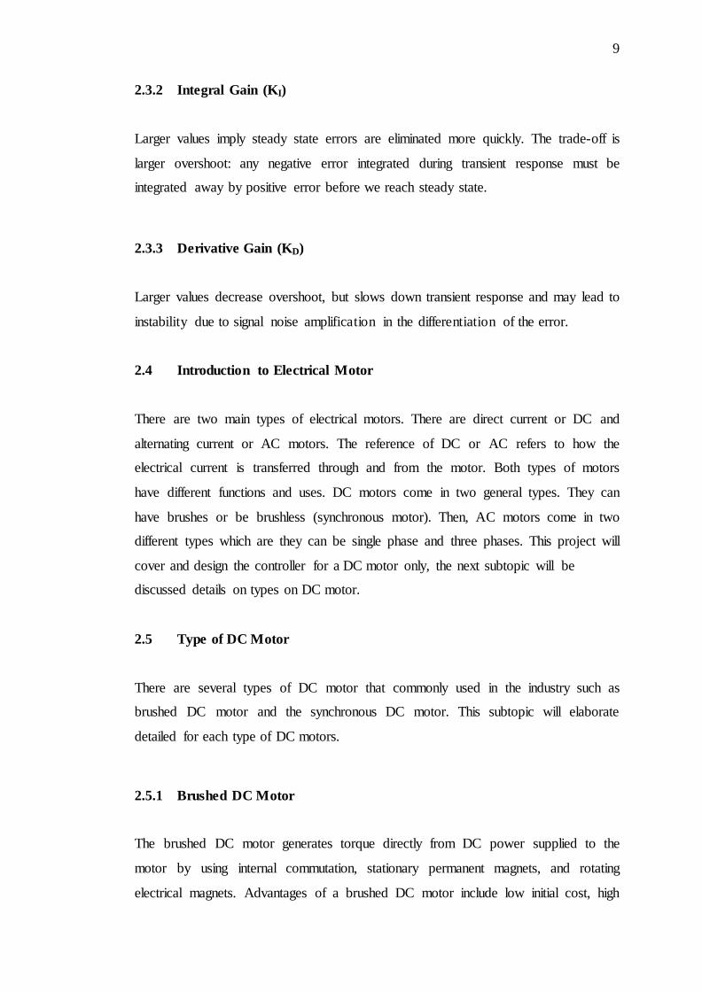
2.5.1 Brushed DC Motor
The brushed DC motor generates torque directly from DC power supplied to the
motor by using internal commutation, stationary permanent magnets, and rotating
electrical magnets. Advantages of a brushed DC motor include low initial cost, high
10
reliability, and simple control of motor speed. Although that, the brushed DC motor
need maintenance regularly by replacing the brushes and springs which carry the
electric current, as well as cleaning or replacing the commutated. These components
are necessary for transferring electrical power from outside the motor to the spinning
wire windings of the rotor inside the motor. The Figure 2-3 below shows the brushed
DC motor.
Figure 2-3: Brushed DC motor
2.5.2 Synchronous DC Motor
There are two types of synchronous DC motor which are the brushless DC motor and
the stepper motor. Both require external commutation to generate torque. The motor
is lock up if driven by DC power.
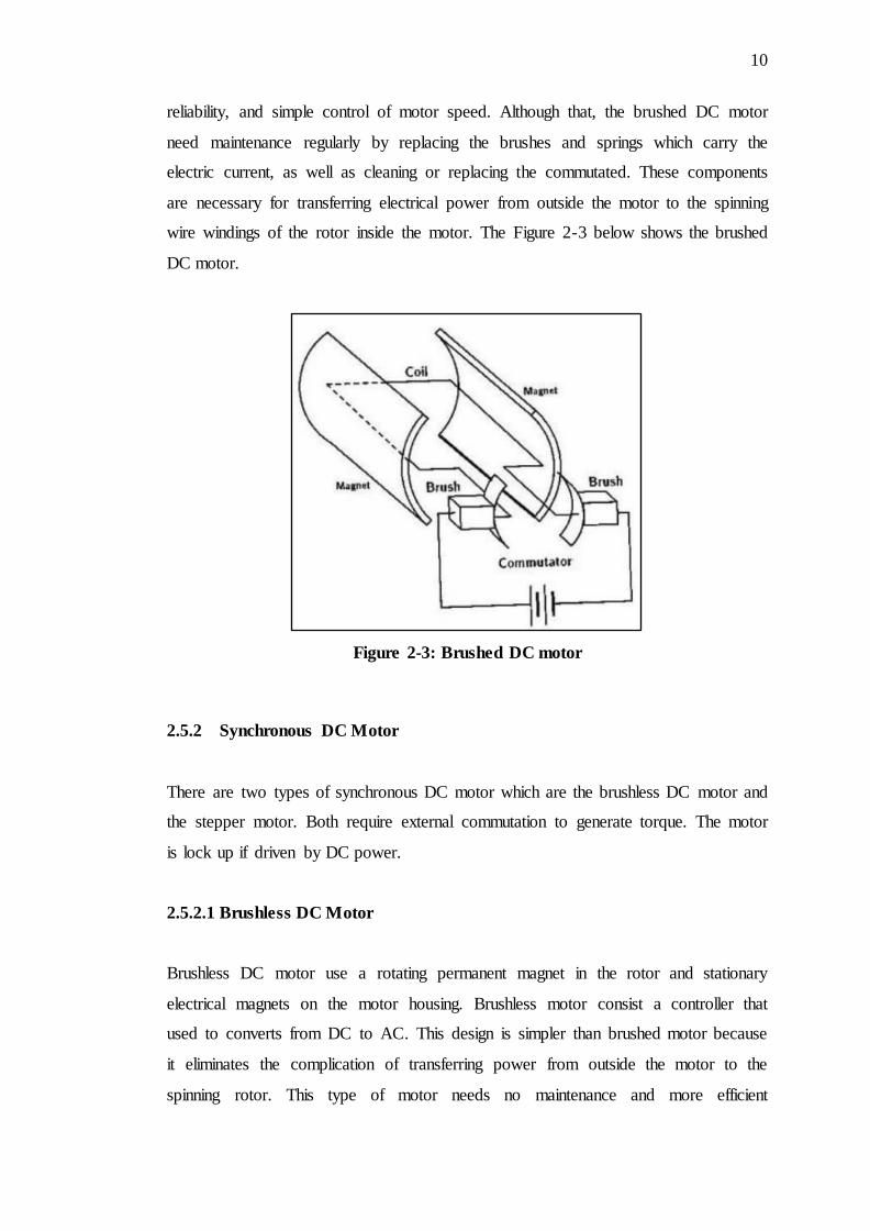
2.5.2.1 Brushless DC Motor
Brushless DC motor use a rotating permanent magnet in the rotor and stationary
electrical magnets on the motor housing. Brushless motor consist a controller that
used to converts from DC to AC. This design is simpler than brushed motor because
it eliminates the complication of transferring power from outside the motor to the
spinning rotor. This type of motor needs no maintenance and more efficient
11
compared to the brushed motor that discussed. Figure 2-4 shows that the brushless
DC motor using three poles to operates.
Figure 2-4: Brushless DC motor
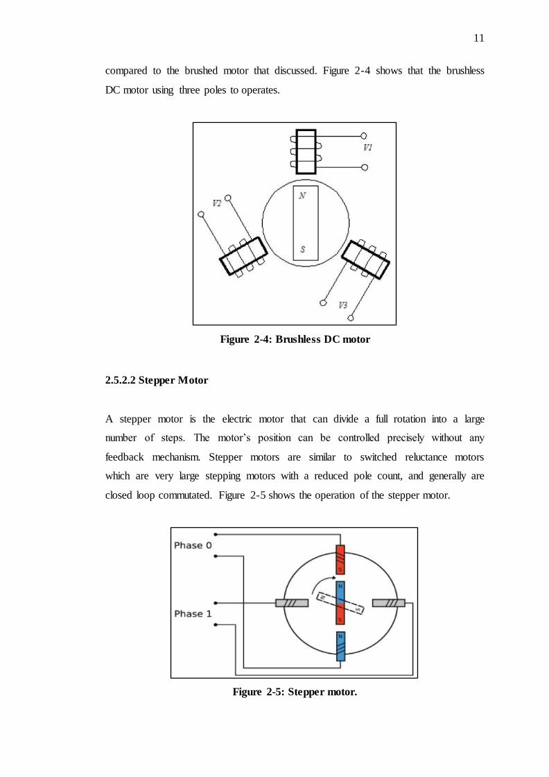
2.5.2.2 Stepper Motor
A stepper motor is the electric motor that can divide a full rotation into a large
number of steps. The motor’s position can be controlled precisely without any
feedback mechanism. Stepper motors are similar to switched reluctance motors
which are very large stepping motors with a reduced pole count, and generally are
closed loop commutated. Figure 2-5 shows the operation of the stepper motor.
Figure 2-5: Stepper motor.
12
2.6 Speed Control Method of DC Motor
The speed of DC motor can be varied by controlling the field flux, the armature
resistance or the terminal voltage that applied to the armature circuit (armature
voltage). The three most common speed control methods are field resistance control,
armature voltage control, and armature resistance control.
2.6.1 Field Resistance Control Method
In the field resistance control method, a series resistance is inserted in the shunt-field
circuit of the motor in order to change the flux by controlling the field current. It is
theoretically expected that an increase in the field resistance will result in an increase
in the load speed of the motor and in the slope of torque speed curve.
2.6.2 Armature Voltage Control Method
In the armature voltage control method, the voltage applied to the armature circuit, is
varied without changing the voltage applied to the field circuit of the motor.
Therefore, the motor must be separately excited to use armature voltage control.
When the armature voltage is increased, the no-load speed of the motor increases
while the slope of torque speed curve remains unchanged since the flux is kept
constant.
2.6.3 Armature Resistance Control Method
The armature resistance control is the less commonly used method for speed control
in which an external resistance is inserted in series with the armature circuit. An
increase in the armature resistance results in a significant increase in the slope of the
torque speed characteristic of the motor while the no-load speed remains constant.
13
2.7 Pulse Width Modulation (PWM)
Pulse-width modulation (PWM), is a modulation technique that conforms the width
of the pulse, formally the pulse duration, based on modulator signal information.
Although this modulation technique can be used to encode information for
transmission, its main use is to allow the control of the power supplied to electrical
devices, especially to inertial loads such as motors.
The average value of voltage (and current) fed to the load is controlled by
turning the switch between supply and load on and off at a fast pace. The longer the
switch is on compared to the off periods, the higher the power supplied to the load is.
The PWM switching frequency has to be much faster than what would affect the
load, which is to say the device that uses the power. Typically switching have to be
done several times a minute in an electric stove, 120 Hz in a lamp dimmer, from few
kilohertz (kHz) to tens of kHz for a motor drive and well into the tens or hundreds of
kHz in audio amplifiers and computer power supplies.
The term duty cycle describes the proportion of 'on' time to the regular
interval or 'period' of time. A low duty cycle corresponds to low power, because the
power is off for most of the time. Duty cycle is expressed in percent, 100% being
fully on.
CHAPTER 3
METHODOLOGY
3.1 Chapter Overview
This chapter will start with the method and alternatives that have been used from the
beginning until the end of this project. Beginning from mathematical modelling of
DC motor until the controller has been designed. In the last part, hardware
implementation using microcontroller to validate and evaluate defuzzification output
from the design FLC controller by performing an open loop test for the system.
15
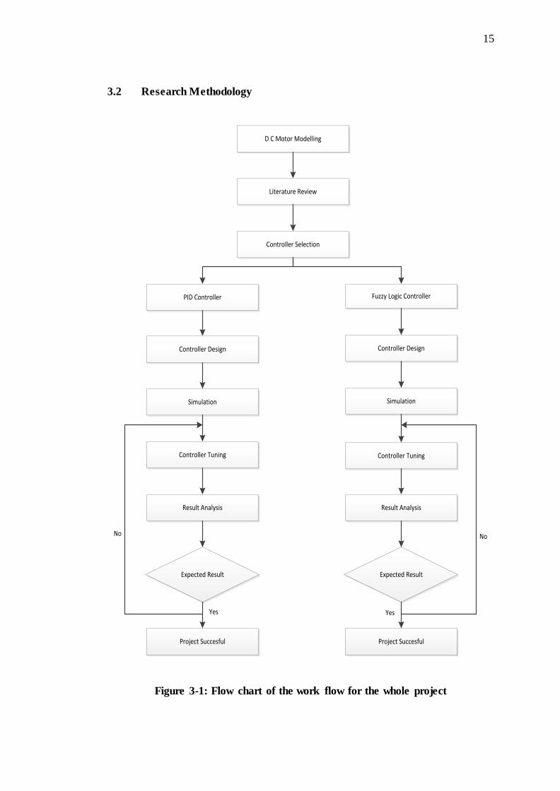
3.2 Research Methodology
D C Motor Modelling
Literature Review
Controller Selection
PID Controller Fuzzy Logic Controller
Controller Design
Simulation
Controller Tuning
Result Analysis
Expected Result
Project Succesful
No
Yes
Controller Design
Simulation
Controller Tuning
Result Analysis
Expected Result
Project Succesful
No
Yes
Figure 3-1: Flow chart of the work flow for the whole project
16
3.3 DC Motor Modelling
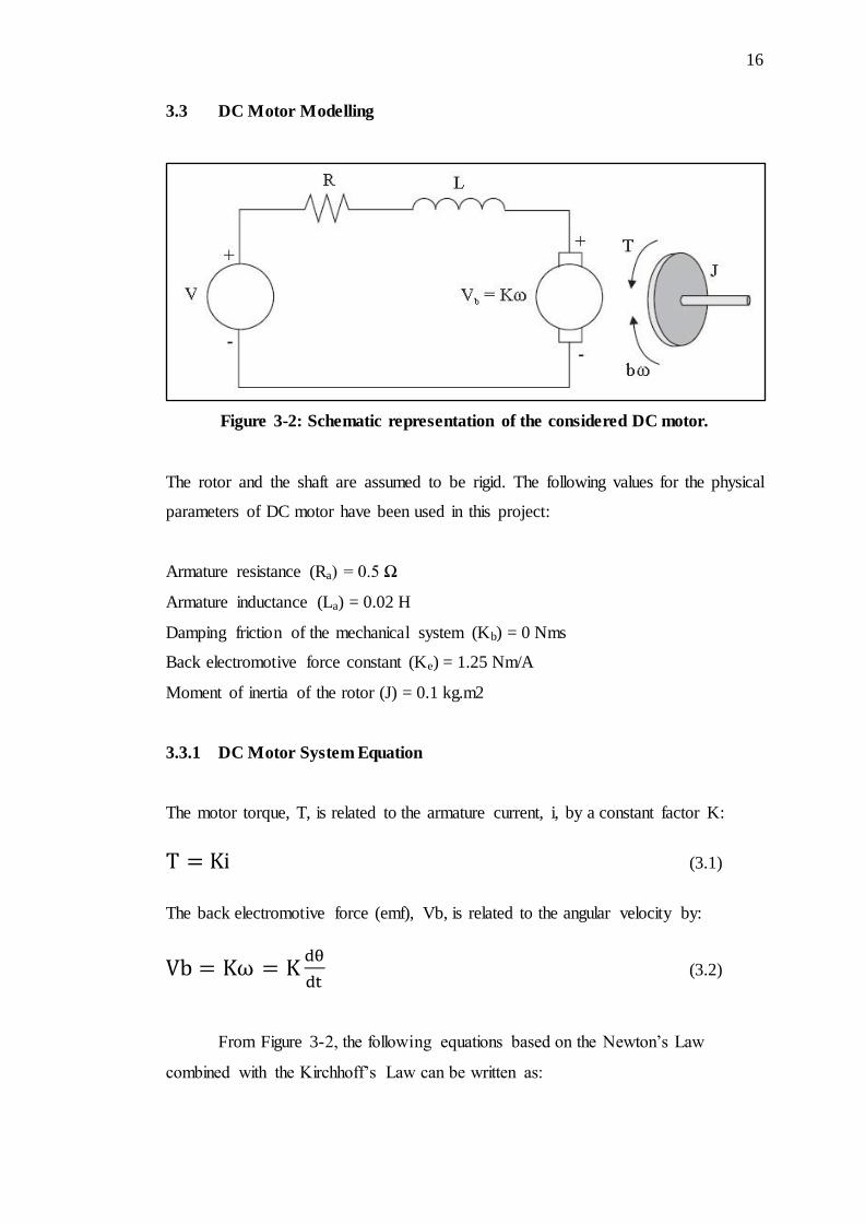
Figure 3-2: Schematic representation of the considered DC motor.
The rotor and the shaft are assumed to be rigid. The following values for the physical
parameters of DC motor have been used in this project:
Armature resistance (Ra) = 0.5 Ω
Armature inductance (La) = 0.02 H
Damping friction of the mechanical system (Kb) = 0 Nms
Back electromotive force constant (Ke) = 1.25 Nm/A
Moment of inertia of the rotor (J) = 0.1 kg.m2
3.3.1 DC Motor System Equation
The motor torque, T, is related to the armature current, i, by a constant factor K:
(3.1)
The back electromotive force (emf), Vb, is related to the angular velocity by:
(3.2)
From Figure 3-2, the following equations based on the Newton’s Law
combined with the Kirchhoff’s Law can be written as:
17
(3.3)
(3.4)
Using the Laplace transform, equations (3.3) and (3.4) can be written as:
(3.5)
(3.6)
where (s) denotes the Laplace operator. From (3.6) we can express I(s):
(3.7)
and substitute it in (3.5) to obtain:
(3.8)
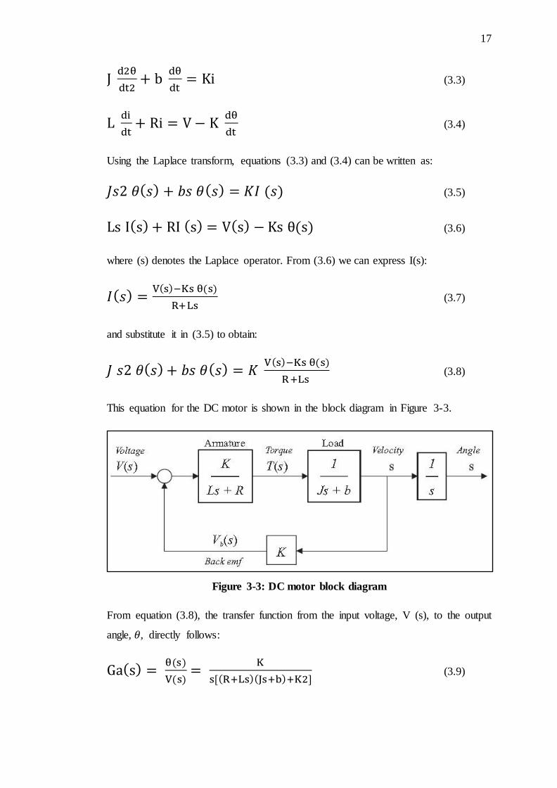
This equation for the DC motor is shown in the block diagram in Figure 3-3.
Figure 3-3: DC motor block diagram
From equation (3.8), the transfer function from the input voltage, V (s), to the output
angle, , directly follows:
(3.9)
18
From the block diagram in Figure 3-3, it is easy to see that the transfer function from
the input voltage, V (s), to the angular velocity, , is:
(3.10)
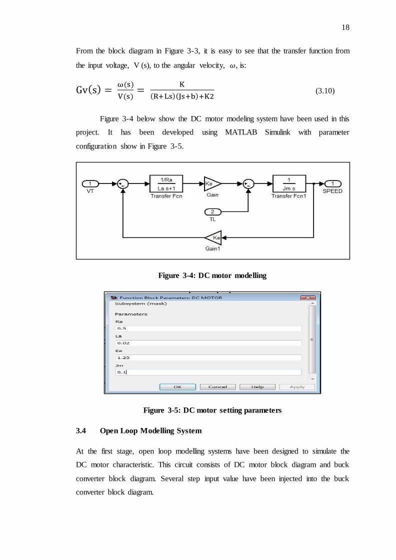
Figure 3-4 below show the DC motor modeling system have been used in this
project. It has been developed using MATLAB Simulink with parameter
configuration show in Figure 3-5.
Figure 3-4: DC motor modelling
Figure 3-5: DC motor setting parameters
3.4 Open Loop Modelling System
At the first stage, open loop modelling systems have been designed to simulate the
DC motor characteristic. This circuit consists of DC motor block diagram and buck
converter block diagram. Several step input value have been injected into the buck
converter block diagram.
19
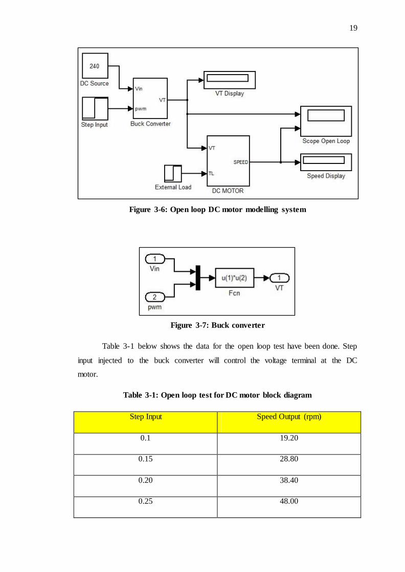
Figure 3-6: Open loop DC motor modelling system
Figure 3-7: Buck converter
Table 3-1 below shows the data for the open loop test have been done. Step
input injected to the buck converter will control the voltage terminal at the DC
motor.
Table 3-1: Open loop test for DC motor block diagram
Step Input Speed Output (rpm)
0.1 19.20
0.15 28.80
0.20 38.40
0.25 48.00
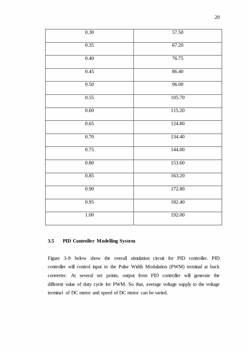
20
0.30 57.50
0.35 67.20
0.40 76.75
0.45 86.40
0.50 96.00
0.55 105.70
0.60 115.20
0.65 124.80
0.70 134.40
0.75 144.00
0.80 153.60
0.85 163.20
0.90 172.80
0.95 182.40
1.00 192.00
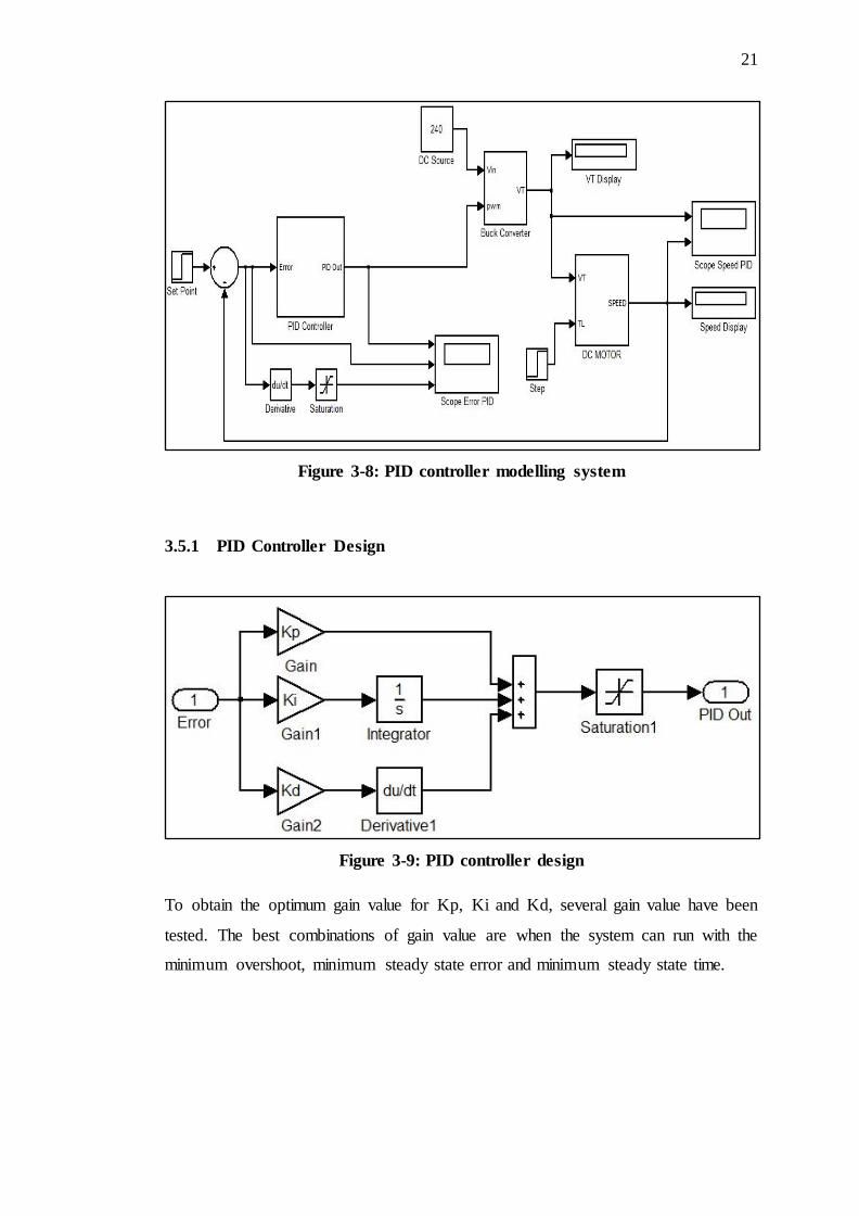
3.5 PID Controller Modelling System
Figure 3-8 below show the overall simulation circuit for PID controller. PID
controller will control input to the Pulse Width Modulation (PWM) terminal at buck
converter. At several set points, output from PID controller will generate the
different value of duty cycle for PWM. So that, average voltage supply to the voltage
terminal of DC motor and speed of DC motor can be varied.
21
Figure 3-8: PID controller modelling system
3.5.1 PID Controller Design
Figure 3-9: PID controller design
To obtain the optimum gain value for Kp, Ki and Kd, several gain value have been
tested. The best combinations of gain value are when the system can run with the
minimum overshoot, minimum steady state error and minimum steady state time.
22
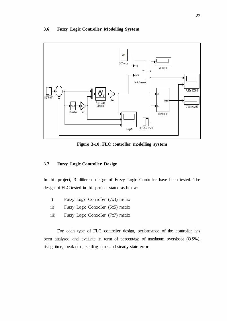
3.6 Fuzzy Logic Controller Modelling System
Figure 3-10: FLC controller modelling system
3.7 Fuzzy Logic Controller Design
In this project, 3 different design of Fuzzy Logic Controller have been tested. The
design of FLC tested in this project stated as below:
i) Fuzzy Logic Controller (7x3) matrix
ii) Fuzzy Logic Controller (5x5) matrix
iii) Fuzzy Logic Controller (7x7) matrix
For each type of FLC controller design, performance of the controller has
been analyzed and evaluate in term of percentage of maximum overshoot (OS%),
rising time, peak time, settling time and steady state error.
23
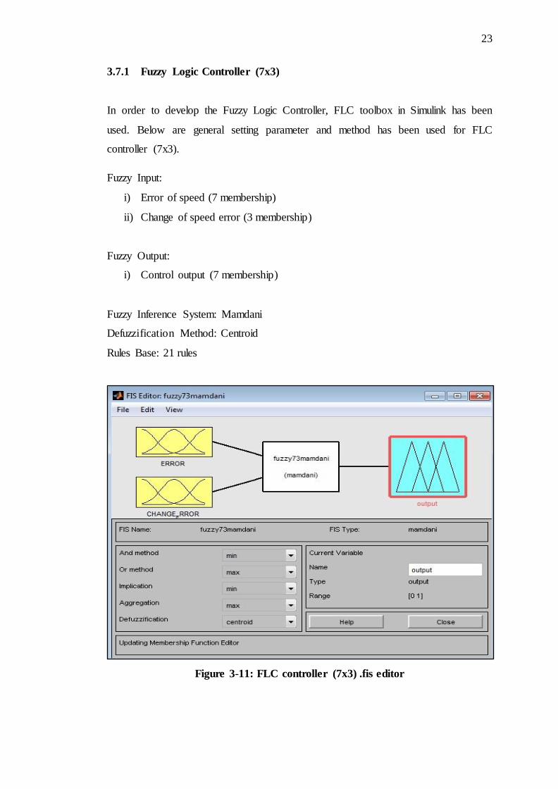
3.7.1 Fuzzy Logic Controller (7x3)
In order to develop the Fuzzy Logic Controller, FLC toolbox in Simulink has been
used. Below are general setting parameter and method has been used for FLC
controller (7x3).
Fuzzy Input:
i) Error of speed (7 membership)
ii) Change of speed error (3 membership)
Fuzzy Output:
i) Control output (7 membership)
Fuzzy Inference System: Mamdani
Defuzzification Method: Centroid
Rules Base: 21 rules
Figure 3-11: FLC controller (7x3) .fis editor
24
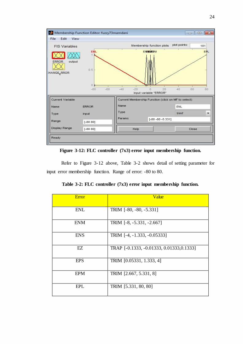
Figure 3-12: FLC controller (7x3) error input membership function.
Refer to Figure 3-12 above, Table 3-2 shows detail of setting parameter for
input error membership function. Range of error: -80 to 80.
Table 3-2: FLC controller (7x3) error input membership function.
Error Value
ENL TRIM [-80, -80, -5.331]
ENM TRIM [-8, -5.331, -2.667]
ENS TRIM [-4, -1.333, -0.05333]
EZ TRAP [-0.1333, -0.01333, 0.01333,0.1333]
EPS TRIM [0.05331, 1.333, 4]
EPM TRIM [2.667, 5.331, 8]
EPL TRIM [5.331, 80, 80]
81
REFERENCES
[1] Chan, C. C, Low Cost Electronic-Controlled Variable Speed Reluctance Motors,
IEEE Transaction on Industrial Electronics, Vol. IE-34, No. 1,95-100, February
1987.
[2] Khoei, A. Hadidi, Kh, Microprocessor Based Closed-Loop Speed Control
System For DC Motor Using Power MOSFET, Elctronics Circuits and Systems,
IEEE International Conference ICECS 96, Vol. 2, 1247-1250, 1996.
[3] K. J. Astrom, T. Hagglund, Automatic Tuning of PID Controllers, Instrument
Society of America, USA, 1998.
[4] K. J. Astrom, B. Wittenmark, Adaptive Control, Addison-Wesley, USA, 1995.
[5] Y.D.Landau, Adaptive Control, Marcel Dekker, New York, 1979.
[6] L. Reznik, Fuzzy Controllers, BH, Victoria University of Technology,
Melbourne, Australia, 1997.
[7] J.S.R. Jang, C.T.Sun, E. Mizutani, Neuro-Fuzzy and Soft Computing, Prentice-
Hall, New Jersey, 1997.
[8] R.J. Wai, C.M. Lin, C.F. Hsu, "Adaptive Fuzzy Sliding Mode Control for
Electrical Servo Drive", Fuzzy Sets and Systems, 143, 2004, pp.295-310.
[9] R.J. Wai, "Robust Fuzzy Neural Network Control for Nonlinear Motor-toggle
Servomechanism",Fuzzy Sets and Systems, 139, 2003, pp. 185-208.
[10] C.H. Chen, Fuzzy Logic and Neural Network Handbook, McGraw-Hill, United
States, 1996.
[11] R. Palm, D. Driankov, H. Hellendoorn, Model Based Fuzzy Control, Springer,
Berlin, 1997.
[12] P. Vas, Artificial-Intelligence-Based Electrical Machines and Drives, Oxford
University Press, New York, 1999.
82
[13] K. M. Passino and S. Yurkovich. Fuzzy Control, EUA, Addison-Wesley, 1998
[14] J. Yen, R. Langari and L.A. Zadeh, Industrial Applications of Fuzzy Logic and
Intelligent Systems. IEEE Press, New York, 1995.
[15]
[16]
E. Monmasson and M.N. Cirstea, FPGA design methodology for industrial
control systems - a review. IEEE Transactions on Industrial Electronics, V. 54,
N. 4, pp. 1824-1842, 2007.
L. Zadeh, " Fuzzy sets" Info & Ctl., Vol. 8,pp. 338-353, 1965.
[17] K. Ogata, Modern Control Engineering, Prentice Hall, 1997.
[18] R.C. Dorf and R.H. Bishop, in: Modern Control Systems, 8th ed., Addison-
Wesley Longman, Inc, 1998
[19]
[20]
M. Salami and G.Gain,"An adaptive PID controller based on genetic algorithm
processor", First International Conference on Genetic Algorithms in
Engineering Systems: Innovation and Applications, pp. 88-93,1995.
E.E. Ibrahiem, M.M., E. Walid and A. Musbah J.,"The adaptive fuzzy designed
PID controller using wavelet network",Computer Science and Information
Systems / ComSIS, Vol. 6, no. 2, pp. 141-163,2009.