d&c manager - quantities manager plan ... is not included in the report phase quantities can be...
TRANSCRIPT

____________________________________ CHAPTER 19
D&C Manager - Quantities 19.1 Introduction Objectives Understand the operational modes of the D&C Manager including
calculating automated quantities.
Project Manager Plan View Design
Tools
Menu Bar Application GEOPAK Road > Design and Computation Manager
GEOPAK 2001MR
The Design and Computation Manager (D&C Manager) is a tool that enables the user to standardize graphics elements for drafting and pay item quantities. To review how to access the Design and Computation manager, see session 7.
One of the major goals of any design project is the cost-effective development of plans production sheets. This includes construction plans, profile sheets, estimated quantities, and various other sheets needed to actually construct the design. Although generic MicroStation commands can be utilized to produce the required sheets, several GEOPAK tools can be used in conjunction with the Design and Computation Manager and these MicroStation commands to help automate the process.
Other GEOPAK tools are within the Design and Computation Manager and various plan view functions:
• Controlling Various MicroStation Copy Functions utilizing the Place Influence option and the Design mode
• Controlling the MicroStation Display Filters (Display mode) • Changing the MicroStation symbology via GEOPAK Items (Set mode) • Identification of plan view areas to incorporate into the automated quantities (Shape mode) • Plan view quantities (Compute mode) • Pavement Markings • Pavement Symbols
19.2 Operational Modes Several operational modes are supported within the Design and Computation Manager. The Design mode was discussed in session 7. In this session, the following modes are reviewed: display, set, shape, compute and pavement markings.
19.2.1 Display Display mode is used to enhance on screen visualization by enabling the user to manipulate the display of GEOPAK intelligent elements.
D&C Manager - Quantities 19-1

GEOPAK® __________________________________________________________
The feature(s) to be visualized are added to the Collection box – the bottom window of the D&C Manager dialog box when set to Display or Compute modes. Individual items or entire categories can be placed in the collection by utilizing the Add to Collection icon as shown below.
Three display options are supported for the display of the items in the Collection box.
• Highlight - changes those items stored in the collection area to the MicroStation highlight color.
• Not - simply turns off the display of the collection items leaving everything else on. • Only - will turn off everything but the collection items.
Before utilizing the display filters, visualization is enhanced if all the elements on the screen are gray, or another singular color, rather than the vast conglomeration of color seen on the screen for a typical project. Therefore, to set the color, select Settings > Display from the menu bar. The Display Preferences dialog box appears.
19.2.2 Set The Set mode allows the user to assign attributes from the ddb database to existing graphical elements in the file. Three methods are available for specifying the graphic elements to be changed: individual element selection, Complex Chain or MicroStation Selection Set.
When changing individual elements, highlight the desired item in the D&C Manager dialog box. Click Set, then datapoint the element to modify, then datapoint off the element to accept.
Complex Chain automatically creates a chain from graphic elements and applies the attributes of the highlighted item in the content box.
19-2 VDOT Road I Training GEOPAK 2001MR

___________________________________________________________GEOPAK®
To modify the symbology of many elements to a single item, create a MicroStation Selection Set of the elements. Next, click Set to transfer the attributes of the item selected in the D&C Manager to the items identified in the MicroStation design file.
19.2.3 Compute An important, yet time-consuming part of any project is the computation of quantities. Through the Compute mode of the Design and Computation Manager, GEOPAK offers tools that make the completion of this task much quicker and easier. In addition, since the software utilizes the plan view construction drawings to compile quantities, discrepancies between the drawings and the tabulated quantities are non-existent. Chosen items within either the View or a Fence are calculated
GEOPAK 2001MR D&C Manager - Quantities 19-3
GEOPAK® __________________________________________________________
19-4 VDOT Road I Training GEOPAK 2001MR
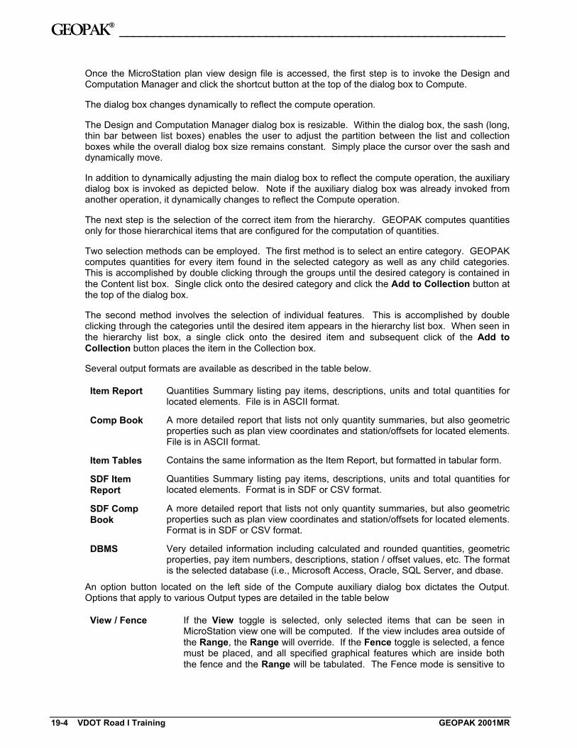
Once the MicroStation plan view design file is accessed, the first step is to invoke the Design and Computation Manager and click the shortcut button at the top of the dialog box to Compute.
The dialog box changes dynamically to reflect the compute operation.
The Design and Computation Manager dialog box is resizable. Within the dialog box, the sash (long, thin bar between list boxes) enables the user to adjust the partition between the list and collection boxes while the overall dialog box size remains constant. Simply place the cursor over the sash and dynamically move.
In addition to dynamically adjusting the main dialog box to reflect the compute operation, the auxiliary dialog box is invoked as depicted below. Note if the auxiliary dialog box was already invoked from another operation, it dynamically changes to reflect the Compute operation.
The next step is the selection of the correct item from the hierarchy. GEOPAK computes quantities only for those hierarchical items that are configured for the computation of quantities.
Two selection methods can be employed. The first method is to select an entire category. GEOPAK computes quantities for every item found in the selected category as well as any child categories. This is accomplished by double clicking through the groups until the desired category is contained in the Content list box. Single click onto the desired category and click the Add to Collection button at the top of the dialog box.
The second method involves the selection of individual features. This is accomplished by double clicking through the categories until the desired item appears in the hierarchy list box. When seen in the hierarchy list box, a single click onto the desired item and subsequent click of the Add to Collection button places the item in the Collection box.
Several output formats are available as described in the table below.
Item Report Quantities Summary listing pay items, descriptions, units and total quantities for located elements. File is in ASCII format.
Comp Book A more detailed report that lists not only quantity summaries, but also geometric properties such as plan view coordinates and station/offsets for located elements. File is in ASCII format.
Item Tables Contains the same information as the Item Report, but formatted in tabular form.
SDF Item Report
Quantities Summary listing pay items, descriptions, units and total quantities for located elements. Format is in SDF or CSV format.
SDF Comp Book
A more detailed report that lists not only quantity summaries, but also geometric properties such as plan view coordinates and station/offsets for located elements. Format is in SDF or CSV format.
DBMS Very detailed information including calculated and rounded quantities, geometric properties, pay item numbers, descriptions, station / offset values, etc. The format is the selected database (i.e., Microsoft Access, Oracle, SQL Server, and dbase.
An option button located on the left side of the Compute auxiliary dialog box dictates the Output. Options that apply to various Output types are detailed in the table below
View / Fence If the View toggle is selected, only selected items that can be seen in MicroStation view one will be computed. If the view includes area outside of the Range, the Range will override. If the Fence toggle is selected, a fence must be placed, and all specified graphical features which are inside both the fence and the Range will be tabulated. The Fence mode is sensitive to

___________________________________________________________GEOPAK®
GEOPAK 2001MR D&C Manager - Quantities 19-5
the MicroStation Inside, Overlap and Clip modes.
File / Preview If set to File, GEOPAK creates the file whose file format is based on the Output type and whose name is defined in the key-in field to the right of the File option. The name can be manually entered or selected via the Files (folder) icon. The file can be created or appended to an existing file. If desired, a full path may be specified, otherwise, the report will be found in the current directory.
If the option is set to Preview, the file is not created and the output is displayed in a GEOPAK window.
Description Any description keyed within this field will be printed at the top of the report. There is a maximum of 48 characters supported for this field.
Display These short cut icons are functionally identical to the Display mode in the main dialog box and are discussed in the next section.\
Highlight in Computation
When activated, all MicroStation elements utilized in computations are highlighted.
Compute Commences the computation process.
Job Number GEOPAK Coordinate geometry database (GPK) file wherein the specified chain is stored.
Chain Requires a minimum of one chain which must be stored in the specified job number.
Select When selected, the Chain Selector dialog box appears, wherein the user can select the desired chain.
Range Left and right offset limits (in master units) from the chain where the quantities will be computed. Any specified item located outside of the limits is not included in the report
Phase Quantities can be separated into various phases, as a means to group various pay items. Default phases include: Design, Preliminary, and Final. Note the user can add new phases, but must be aware of naming limitations of downstream applications (i.e., Transport links in Quantities Manager.)
Run The user may also runs as a method of grouping various quantities and / or pay items.
19.2.4 Shape The placement of shapes for area quantities is simple and fast when utilizing the shape mode. In order to place a shape, GEOPAK must identify a closed area. This area can be defined by intersecting elements, which do not have to be clipped or shortened to define the closed area. There are three options for placing shapes depending on the complexity of the plan view and the type of area where quantities are desired:
• Automatic - best utilized when the elements forming the shape do not conflict with other elements in the view.
• Semi-auto - utilized when the plan view has more conflicting elements or where the selection of an area produces very small shapes. In this method, the user is prompted when each element is selected to determine the path of the software in producing shapes.

GEOPAK® __________________________________________________________
• Exclusive - This option utilizes the automatic option, but in addition, prompts the user for the identification of an area inside the original shape that is excluded from the area quantity. The Exclude mode is useful for curb and gutter around a traffic island.
Any of the three options may be chosen during the course of shape placement. To change from one option to another, simply adjust the option button on the right side of dialog box.
19.2.5 Pavement Marking
The Pavement Marking mode allows the user to place pavement marking including striping, and symbols.
19-6 VDOT Road I Training GEOPAK 2001MR
___________________________________________________________GEOPAK®
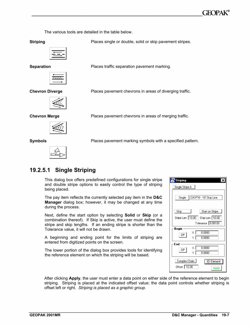
The various tools are detailed in the table below.
Striping
Places single or double, solid or skip pavement stripes.
Separation
Places traffic separation pavement marking.
Chevron Diverge
Places pavement chevrons in areas of diverging traffic.
Chevron Merge
Places pavement chevrons in areas of merging traffic.
Symbols
Places pavement marking symbols with a specified pattern.
19.2.5.1 Single Striping This dialog box offers predefined configurations for single stripe and double stripe options to easily control the type of striping being placed.
The pay item reflects the currently selected pay item in the D&C Manager dialog box; however, it may be changed at any time during the process.
Next, define the start option by selecting Solid or Skip (or a combination thereof). If Skip is active, the user must define the stripe and skip lengths. If an ending stripe is shorter than the Tolerance value, it will not be drawn.
A beginning and ending point for the limits of striping are entered from digitized points on the screen.
The lower portion of the dialog box provides tools for identifying the reference element on which the striping will be based.
After clicking Apply, the user must enter a data point on either side of the reference element to begin striping. Striping is placed at the indicated offset value; the data point controls whether striping is offset left or right. Striping is placed as a graphic group.
GEOPAK 2001MR D&C Manager - Quantities 19-7

GEOPAK® __________________________________________________________
19.2.5.2 Double Striping The process for Double Striping is the same as Single, except for having two pay item placement options, Inside and Outside and a user definable Distance Between Stripes. The user must select either the Inside or Outside button for the highlighted (D&C Manager) pay item to be displayed in the dialog box. Separate quantities are calculated for each stripe.
The remaining process is the same as described above.
19.2.5.3 Separation This option draws pavement markings between two sets of selected elements. Elements may be either GEOPAK or MicroStation generated.
Once a pay item has been selected, the user may set the Distance Between Stripes and the Slash Stripe Angle. Tolerance functions the same as for striping.
A Begin DP and End DP should be issued before the Reference DP is identified. The Reference DP must fall between the beginning and ending DP. It marks the location of the first pavement marking and determines the direction of the slashed stripe. All other markings will be based on the first stripe.
Tools for defining the limits of the pavement markings are located at the bottom of the Separation dialog box. ID Intersection identifies the elements where the striping will terminate. ID Location is the set of elements from which the striping begins.
After the Apply button is selected, the user must issue a data point in the graphics file for the pavement markings to be displayed.
19-8 VDOT Road I Training GEOPAK 2001MR
___________________________________________________________GEOPAK®
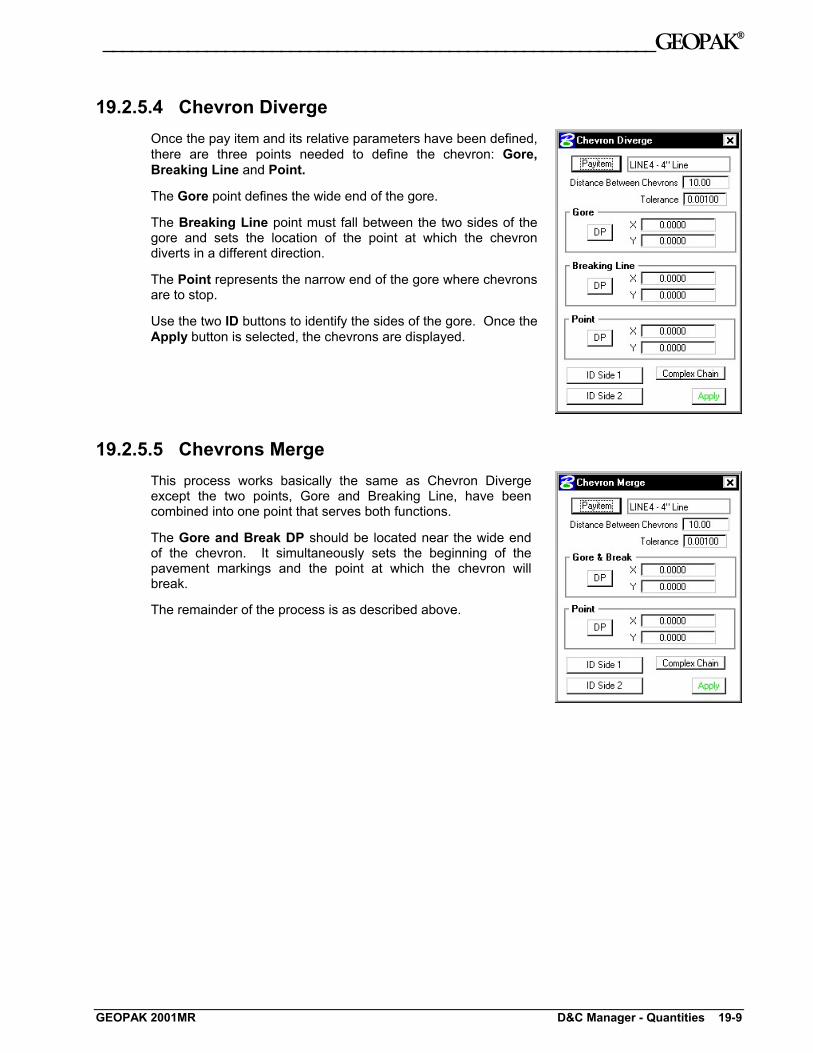
19.2.5.4 Chevron Diverge Once the pay item and its relative parameters have been defined, there are three points needed to define the chevron: Gore, Breaking Line and Point.
The Gore point defines the wide end of the gore.
The Breaking Line point must fall between the two sides of the gore and sets the location of the point at which the chevron diverts in a different direction.
The Point represents the narrow end of the gore where chevrons are to stop.
Use the two ID buttons to identify the sides of the gore. Once the Apply button is selected, the chevrons are displayed.
19.2.5.5 Chevrons Merge This process works basically the same as Chevron Diverge except the two points, Gore and Breaking Line, have been combined into one point that serves both functions.
The Gore and Break DP should be located near the wide end of the chevron. It simultaneously sets the beginning of the pavement markings and the point at which the chevron will break.
The remainder of the process is as described above.
GEOPAK 2001MR D&C Manager - Quantities 19-9

GEOPAK® __________________________________________________________
19.2.5.6 Symbols The Cell Group Info defines the cells to be placed.
Layout enables the user to repeat the cells, and to set the locations of where the cells are placed. The cells can be placed offset to element(s) in a MicroStation Selection Set, Complex chain or any COGO Chain.
The Limits can be defined via XY coordinate pairs projected to the elements in the Selection Set or Complex Chain. If a COGO chain is utilized, beginning and ending stations fields are utilized.
Once all values are set as desired, click Apply to begin placing the cells. One additional DP is required to define the offset direction relative to the selected element.
** Note: This dialog box works in conjunction with the pulldown User > Hierarchical Paths on the main dialog box. The symbols dialog box searches all items listed under the category specified by Hierarchical Paths and then lists all cells referred to by those items.
19-10 VDOT Road I Training GEOPAK 2001MR

___________________________________________________________GEOPAK®
LAB 19: Quantities with D&C Manager 19.1 Accessing Plans Production Tools
Step 1. Execute C:\data\geo\VDOT\road1\LAB19.EXE.
Step 2. Open the MicroStation file c:\data\geo\vdot\road1\d17682des.dgn.
Step 3. Access the Road Workflow dialog box in Project Manager.
Click the Plan View Design button. This opens the Plan View Design tools tool frame. Open Design and Computation Manager by clicking the left most icon.
Step 4. D&C Manager should open up to the standard VDOTenglish.ddb.
Navigate to the category Road Design > Curbing as shown.
GEOPAK 2001MR LAB 19: Quantities with D&C Manager 19-11

GEOPAK® __________________________________________________________
19.2 Compute Quantities Step 1. Set the current D&C mode to Compute.
Highlight the item 012020 Standard Curb CG-2. This will make it the active item for computing quantities.
Step 2. Set the output option to Item Report in the supplemental dialog box.
Step 3. Since we are doing the quantities based on what is displayed in View 1, be certain to fit all graphics in View 1.
Step 4. Before clicking the Compute button, use the Display options to make sure there are graphics to compute for this item.
By clicking on the icon as shown below, all graphics except the appropriate curb graphics should be turned off.
Step 5. Click Compute. Review the output.
19-12 VDOT Road I Training GEOPAK 2001MR

___________________________________________________________GEOPAK®
Dismiss the Output dialog box.
Step 6. Now let’s see how to compute multiple items at one time.
Returning to the main D&C dialog box, add the curb item to the collection box as shown:
GEOPAK 2001MR LAB 19: Quantities with D&C Manager 19-13

GEOPAK® __________________________________________________________
Step 7. Navigate down and add another curb item to the collection box as shown:
Step 8. Click Compute. Review the output.
Dismiss the Output dialog box.
Step 9. Exit Design and Computation Manager.
Step 10. Exit MicroStation.
19-14 VDOT Road I Training GEOPAK 2001MR