dc m2 oled meter instructions · 2016-05-10 · dc functions (1830, 1832, 1833, 1834) 1830 dc soc...
TRANSCRIPT
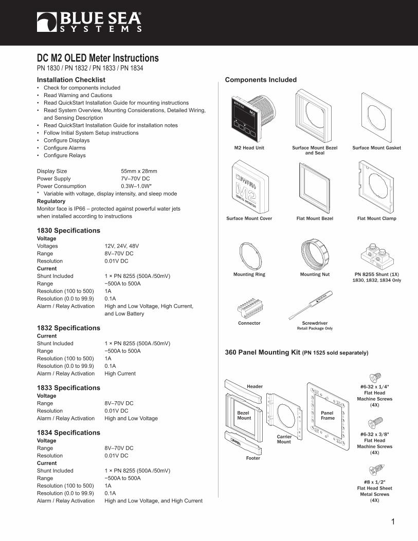
DC M2 OLED Meter InstructionsPN 1830 / PN 1832 / PN 1833 / PN 1834 Installation Checklist • Check for components included • Read Warning and Cautions • Read QuickStart Installation Guide for mounting instructions • Read System Overview, Mounting Considerations, Detailed Wiring, and Sensing Description • Read QuickStart Installation Guide for installation notes • Follow Initial System Setup instructions • Configure Displays • Configure Alarms • Configure Relays
Display Size 55mm x 28mmPower Supply 7V–70V DCPower Consumption 0.3W–1.0W** Variable with voltage, display intensity, and sleep modeRegulatoryMonitor face is IP66 – protected against powerful water jetswhen installed according to instructions
1830 SpecificationsVoltage Voltages 12V, 24V, 48VRange 8V–70V DCResolution 0.01V DCCurrent Shunt Included 1 × PN 8255 (500A /50mV) Range −500A to 500A Resolution (100 to 500) 1AResolution (0.0 to 99.9) 0.1AAlarm / Relay Activation High and Low Voltage, High Current, and Low Battery
1832 SpecificationsCurrent Shunt Included 1 × PN 8255 (500A /50mV) Range −500A to 500A Resolution (100 to 500) 1AResolution (0.0 to 99.9) 0.1AAlarm / Relay Activation High Current
1833 SpecificationsVoltage Range 8V–70V DCResolution 0.01V DCAlarm / Relay Activation High and Low Voltage
1834 SpecificationsVoltage Range 8V–70V DCResolution 0.01V DCCurrent Shunt Included 1 × PN 8255 (500A /50mV) Range −500A to 500A Resolution (100 to 500) 1AResolution (0.0 to 99.9) 0.1AAlarm / Relay Activation High and Low Voltage, and High Current
Components Included
M2 Head Unit Surface Mount Gasket
Mounting Ring
Surface Mount Bezel and Seal
Mounting Nut
Flat Mount Bezel
ScrewdriverRetail Package Only
Connector
BezelMount
Footer
Header
CarrierMount
#6-32 x 1/4"Flat Head
Machine Screws(4X)
#6-32 x 3/8"Flat Head
Machine Screws(4X)
Surface Mount Cover Flat Mount Clamp
Panel Frame
#8 x 1/2"Flat Head Sheet
Metal Screws(4X)
PN 8255 Shunt (1X)1830, 1832, 1834 Only
360 Panel Mounting Kit (PN 1525 sold separately)
1

Resource Information State of Charge (SOC) http://bluesea.com/viewresource/1324 AC Current Measurement http://bluesea.com/viewresource/86
Warning and Caution Symbols WARNING: The symbol refers to possible injury to the user or significant damage to the meter if the user does not follow the procedures.
CAUTION: The symbol refers to restrictions and rules with regard to preventing damage to the meter.
WARNING • Verify that all AC sources are disconnected before connecting or disconnecting the current transformer. Failure to do so will generate lethal voltages on the current transformer. • If you are not knowledgeable about electrical systems, have an electrical professional install this unit. The diagrams in these instructions pertain to the installation of M2 Digital Meters and not to the overall wiring of the vessel. • If an inverter is installed on the vessel, its power leads must be disconnected at the battery before the meter is installed. • If an AC generator is installed on the vessel, it must be stopped and rendered inoperable before the meter is installed. • Verify that no other DC or AC sources are connected to the vessel’s wiring before installing the meter.
CAUTION • The back of the unit is not waterproof. Do not install where the back of the meter is exposed to water.
Installation 1. The M2 State of Charge (SoC) Monitor must be connected to a non-switched circuit to ensure accurate and consistent State of Charge monitoring. 2. Make all connections to the meter’s terminal block before connecting the terminal block to the unit. Keep hands away from the terminal block when applying power to the meter. 3. As the final DC connection, insert a fuse into the in-line fuse holder on the wire to the positive (+) battery terminal.
Mounting Templates
Flat Mount
3.34
" (8
4.8m
m) 3.00" (76.2m
m)
3.00" (76.2mm)
3.34" (84.8mm)
Surface Mount
3.40" (86.5mm)
3.46
" (8
7.9m
m)
Ø2.125"(54mm)
2
STEP 1
PanelFrame
360 Panel Mount Carrier
Use 1/4"MountingScrews
STEP 2
Footer
PanelFrame
Bezel
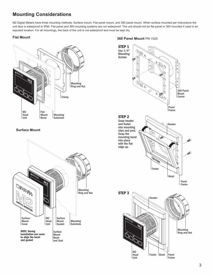
HeaderSnap headerand footerinto mountingclips and post.Snap the mounting bezelinto placewith the flatedge up.
STEP 3
PanelFrame
BezelFooter
Header
M2HeadUnit
MountingRing and Nut
Mounting Substrate
Clamp
Flat Mount Bezel
M2HeadUnit
MountingRing and Nut
Mounting Substrate
M2HeadUnit
SurfaceMount Bezeland Seal
MountingRing and Nut
SurfaceMount Gasket
SurfaceMountCover
NOTE: During installation use cover to align the bezel and gasket
Flat Mount
Surface Mount
360 Panel Mount PN 1525
Mounting Considerations M2 Digital Meters have three mounting methods: Surface mount, Flat panel mount, and 360 panel mount. When surface mounted per instructions the unit face is waterproof to IP66. Flat panel and 360 mounting systems are not waterproof. The unit should not be flat panel or 360 mounted if used in an exposed location. For all mountings, the back of the unit is not waterproof and must be kept dry.
3

DC Functions (1830, 1832, 1833, 1834) 1830 DC SoC Monitor measures the voltages of up to three battery banks and current draw on one battery bank. Provides battery State of Charge (SoC), capacity, amp hours (Ah) remaining, and charge cycles. 1832 DC Ammeter measures current draw of up to 2 battery banks. 1833 DC Voltmeter measures the voltages of up to four battery banks. 1834 DC Multimeter measures the voltages of up to three battery banks and current draw on one battery bank.
Connections IMPORTANT! The Sensing Description section of this manual gives important details to the location of sensors in the AC and DC electrical systems of the boat. Improper location and configuration of sensors can result in erroneous readings and possible damage to components.
Pin-out Tables
Meter Power Supply Connections All meters must have pins 1 (DC Neg.) and 2 (DC Pos.) connected. These pins are used to provide power to the meter. Connect pin 1 to ground and pin 2 to a 12V to 48V power source. Note on some DC meters pin 2 is also used to monitor additional voltages.
DC Connections DC Current
Some DC Meters (SoC, Ammeter, and Multimeter) require use of a “shunt.” Shunts must be connected between the negative terminal on Battery 1 and the main negative bus. All loads and charge sources should have their negative terminals on the main negative bus, with the exception of the M2 negative source which must be connected directly to the battery side of the shunt. Shunt sense wires must be a twisted pair from shunt to the M2 Meter for proper calculation of State of Charge (SoC). Twisted pair wire can be purchased from electrical supply companies, or made by twisting by hand or with an electric drill motor. The current (Amperage) reading for Battery 1 should be negative when it is not being charged and DC power is being used (loads are active). If not, reverse the twisted pair DC shunt sense leads.
It is possible to connect the DC shunt on the positive side of the circuit without a Shunt Shifter (for example on the output side of an alternator) however the measurements will only be accurate to +/- 4%, as opposed to +/-1% on the negative side.
DC Voltage
DC positive(+) voltage supply wires for M2 Meters should be directly connected to the positive battery terminal with a dedicated wire before any other connections. This will ensure correct voltage and SoC monitoring. Use an appropriate in-line fuse (5A suggested) on the positive wire. A twisted pair should be used for V1 (PNs 1830, 1833, 1834) and for V2 (PN 1833).
1830 Connector Pin Assignment Table8 Pin Connector* Function
1 Required Connection
2 Required Connection
*The 8 pin low voltage connector supports wire sizes from 16-26 AWG
3
4
5
6
7
8
DC Negative
DC Supply/Battery 2 +
Relay DC Out to Load
Relay DC +/Battery 3 +
Shunt 1 –
Shunt 1 +
Battery 1 –
Battery 1 +
USB Micro USB Port
1832 Connector Pin Assignment Table8 Pin Connector* Function
1 Required Connection
2 Required Connection
3
4
5
6
7
8
DC Negative
DC Supply
Relay DC Out to Load
Relay DC +
Shunt 1 –
Shunt 1 +
Shunt 2 –
Shunt 2 +
USB Micro USB Port
*The 8 pin low voltage connector supports wire sizes from 16-26 AWG
1833 Connector Pin Assignment Table8 Pin Connector* Function
1 Required Connection
2 Required Connection
3
4
5
6
7
8
DC Negative
DC Supply/Battery 3 +
Relay DC Out to Load
Relay DC +/Battery 4 +
Battery 2 –
Battery 2 +
Battery 1 –
Battery 1 +
USB Micro USB Port
*The 8 pin low voltage connector supports wire sizes from 16-26 AWG
1834 Connector Pin Assignment Table8 Pin Connector* Function
1 Required Connection
2 Required Connection
3
4
5
6
7
8
DC Negative
DC Supply/Battery 2 +
Relay DC Out to Load
Relay DC +/Battery 3 +
Shunt 1 –
Shunt 1 +
Battery 1 –
Battery 1 +
USB Micro USB Port
*The 8 pin low voltage connector supports wire sizes from 16-26 AWG
4
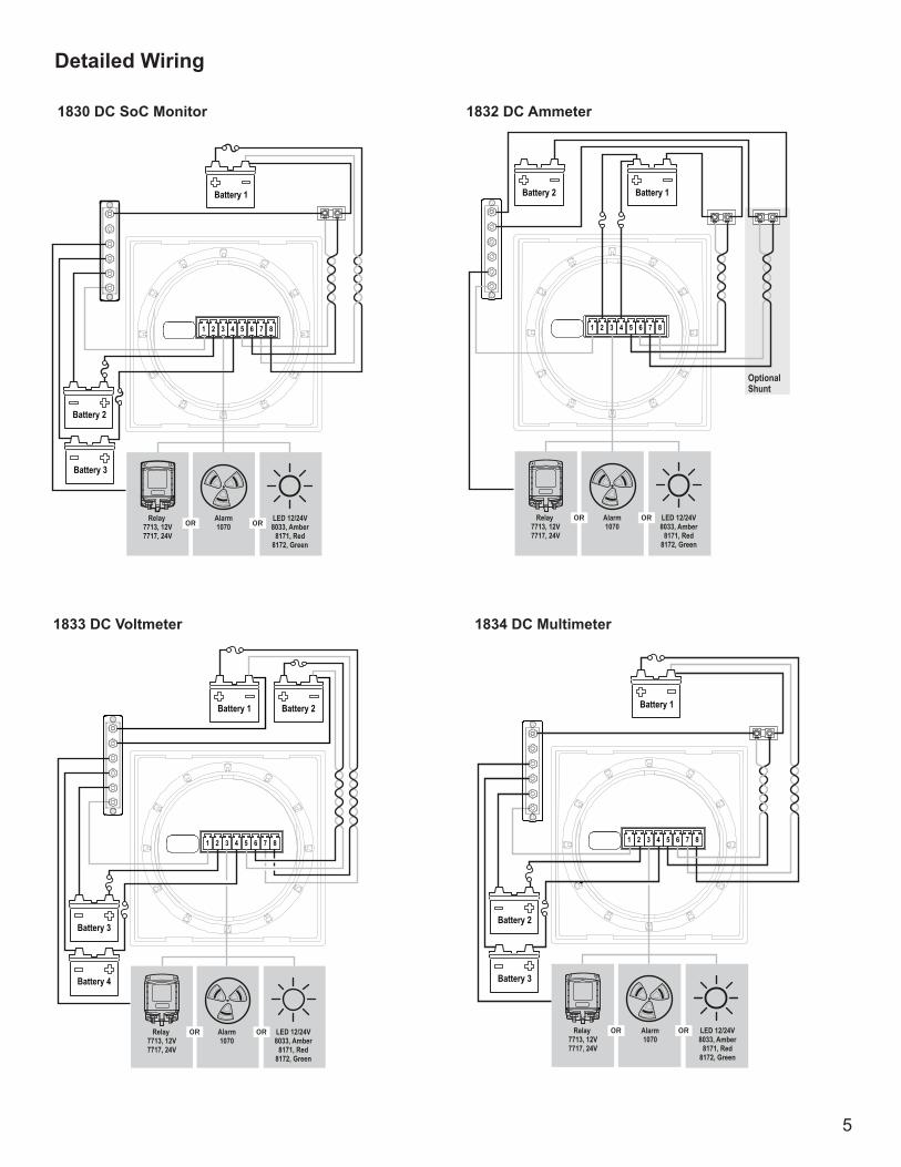
1830 DC SoC Monitor
OROR
1 2 3 4 5 6 7 8
Battery 2
Battery 3
Battery 1
Alarm1070
Relay 7713, 12V7717, 24V
LED 12/24V8033, Amber
8171, Red8172, Green
1832 DC Ammeter
OROR
1 2 3 4 5 6 7 8
Battery 2 Battery 1
OptionalShunt
Alarm1070
Relay 7713, 12V7717, 24V
LED 12/24V8033, Amber
8171, Red8172, Green
1833 DC Voltmeter
OROR
1 2 3 4 5 6 7 8
Battery 1 Battery 2
Battery 3
Battery 4
Alarm1070
Relay 7713, 12V7717, 24V
LED 12/24V8033, Amber
8171, Red8172, Green
1834 DC Multimeter
OROR
1 2 3 4 5 6 7 8
Battery 2
Battery 3
Battery 1
Alarm1070
Relay 7713, 12V7717, 24V
LED 12/24V8033, Amber
8171, Red8172, Green
Detailed Wiring
5
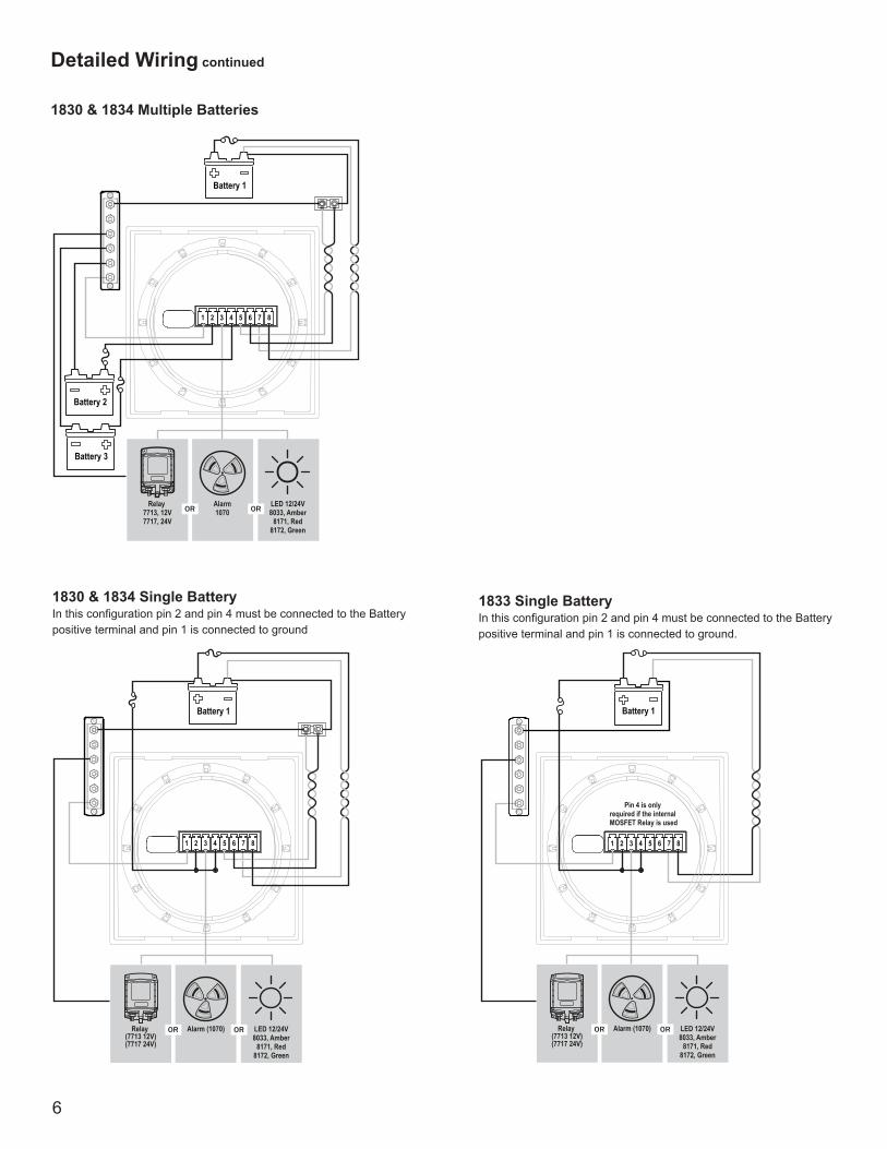
1830 & 1834 Multiple Batteries
OROR
1 2 3 4 5 6 7 8
Battery 2
Battery 3
Battery 1
Alarm1070
Relay 7713, 12V7717, 24V
LED 12/24V8033, Amber
8171, Red8172, Green
1 2 3 4 5 6 7 8
Battery 1
Relay (7713 12V)(7717 24V)
Alarm (1070) OROR LED 12/24V8033, Amber
8171, Red8172, Green
1830 & 1834 Single Battery In this configuration pin 2 and pin 4 must be connected to the Battery positive terminal and pin 1 is connected to ground
Relay (7713 12V)(7717 24V)
Alarm (1070) OROR
1 2 3 4 5 6 7 8
Battery 1
LED 12/24V8033, Amber
8171, Red8172, Green
Pin 4 is only required if the internal MOSFET Relay is used
1833 Single BatteryIn this configuration pin 2 and pin 4 must be connected to the Battery positive terminal and pin 1 is connected to ground.
Detailed Wiring continued
6

4
3
Relay SupplyPin 4 voltage connections are only required if the relay is used or if the battery monitor function is used.
Optically isolated relay control
500mA DC Maximum current
M2 Relay Connections M2 Meters contains an internal MOSFET relay that can drive external DC loads up to 0.5A. The input is protected with a thermally activated auto-reset-ting fuse that will protect against shorts. In addition, an inline fuse rated at 5A should be used to protect against shorts. In typical applications, a power source is connected to the Relay+ pin and a load is connected to the Relay Out to Load connection. In the P/Ns 1830, 1833, and 1834 meters, the Relay+ connection can also be used to monitor a voltage.
External LED
An external LED such PN 8171 can be connected to the Relay Output terminal. If the system is going to operate at more than 24V nominal, an additional 4K Ohms of resistance should be placed in-line with the LED.
1 2 3 4 5 6 7 8
LED,12V/24V8033, Amber8171, Red8172, Green
LED Supply8 to 70V
Yellow Wire
Red Wire
7

1 2 3 4 5 6 7 8
A B
NOTE: For optional SPST switch connectionsWire connections are the same as the SPDT, ON-ON except the Ground is omitted.
No Connectionorangegreenbrown
CONTROL (red)
GROUND (black)
LED OUTPUT (yellow)
12V or 24V DC
Refridgerator
External Relay
If you need to switch more than 0.5 A, you can use an external relay such as PN 7713, 12V or PN 7717, 24V Remote Battery Switch. Connect the Relay+ terminal to the red control wire. Activating the internal relay will also activate PN 7713.
NOTE: 9012, 7700, 7701, 7702, & 7703 Remote Battery Switches are not compatible with the internal relay.
1 2 3 4 5 6 7 8
External Alarm Supply5 to 30V DC
+ Red
- Silver1070
External Alarm (1070 Floyd Bell Turbo)
The Relay+ terminal can support an external audible alarm. Such as the Floyd Bell Turbo Alarm (PN 1070).
8

Getting Started Example Screens From PN 1830 SoC Monitor
When an M2 Meter is initially powered up, it will display the Blue Sea Systems Logo,its serial number and its Software revision. After a couple of seconds, the unit will display a high-level System Summary screen.
Pressing any button will display a temporary pop-up menu. Select an option by pressing the button beneath it. The pop-up menu will disappear after the first button is pressed.
The menu system is a two dimensional matrix. Pressing the UP ↑ or DOWN ↓ arrow buttons will transition the display between the System Summary screen which displays summary information for each of the “voltage” or “current” channels.
Press the Next button to display more detailed information about an input channel or to show a single parameter, such as “voltage” in the display (see example below).
Press the Menu button to bring up a shortcut menu to for additional summary screens as well as to access the Setup menus. Press the UP ↑ and DOWN ↓ arrow buttons to move the cursor over the options and press the Select button to see a selected display. To return to the previous display, press the Back button.
9

Configuring the Meter Meter settings can be configured from the Setup menu. This menu can be accessed by pressing the Menu button and then scrolling to and selecting Setup. Press the UP ↑ and DOWN ↓ arrow buttons to move the cursor. The different setup options are described below.
Alarm Setup & Control The meter’s alarm can be set to trigger under certain conditions of battery voltage, current, or state-of-charge. Alarms can be set from the Alarm Setup menu. To get there, first navigate to the Setup menu. Then scroll to Alarm Setup and press the Select button.
Setting Alarms
The M2 Meter family provides monitoring capability of input channels. The meter can monitor Voltage, Current, and Frequency. Alarms are triggered if a channel is above or below a certain user selected threshold value. (Note: not every meter supports every alarm) The following example indicates how to setup an over voltage Alarm.
1.Go to the Alarm Setup menu. 2.Scroll to the desired input channel (i.e, DC1 Volts Hi). 3.Press the Select button and the cursor should start blinking. 4.Set the voltage threshold using the ← and → buttons. (Holding down the buttons allows faster selection) 5.Press the Enter button to save the change or the Cancel button to cancel any change.
NOTE: A low voltage threshold cannot be set above a high voltage threshold. Likewise, a high voltage threshold cannot be set below the low voltage threshold. The meter will automatically increase or decrease the voltage thresholds to enforce this.
In the above example, an alarm will set anytime DC1 voltage is greater than or equal to 17V.
10

Voltage Alarm
Voltage alarms can be set for high (Hi) or low (Lo) voltage conditions.
Current Alarm
The current alarm can only be set for over current conditions.
State-of-Charge (SoC) Alarm (PN 1830 Only)
The state-of-charge alarm can only be set if the state of charge is below a certain threshold.
Clearing Alarms
When an alarm occurs, the buzzer will sound, the red ALARM LED will light, and the screen will display which alarm was triggered, the Alarm set point and the current value. Pressing any button silences the buzzer and another button press returns to the previous display.
Until the cause of the alarm is resolved, the ALARM LED will remain on and the channel that triggered the alarm (Voltage, Current, State-of-Charge, or Frequency) will blink.
Viewing Alarms Status
For any active alarm, the parameter will flash if it is displayed. To view a complete list of active alarms, press Menu>Setup>Alarm Setup. Any active alarm will flash. You may have to scroll through the menu to see all of the alarms.
Relay Setup & Control M2 Meters provide an option to control an external relay. The M2 can trigger the relay based on Voltage, Current, or State-of-Charge or Frequency.
These relay options can be set from the Relay Setup menu. To get there, first navigate to the Setup menu. Then scroll to Relay Setup and press the Select button.
Relay Normally On/Off
This setting sets the normal operating state of the connected relay. The options are ON or OFF where ON means the relay is on (contacts closed) in normal operation and OFF means it is normally off (open contacts). Scroll to Relay Normally, press Select (selection will flash), then press the LEFT ← or RIGHT → arrow buttons to change the setting. Press Enter to save your selection. Press Cancel to cancel a change.
11

Notification
The Notification setting controls whether or not a notification is displayed when a relay is activated. Notifications will show which relay threshold was surpassed and for which channel. Scroll to Notification and press Select to change the setting. Press the LEFT ← or RIGHT → arrow buttons to choose either ON or OFF. ON will display notifications and OFF will not. Use this option if you don’t want to be notified that the relay is activating. Press Enter to save the setting or Cancel to cancel a change.
Silence Relay Turn this option on if you want the relay to de-activate after the user presses a key on the display. The key press will only de-activate the relay and will not engage any functions on the meter. For example, this option could be used to silence an external buzzer. Scroll to Silence and press Select to change the setting. Press the LEFT ← or RIGHT → arrow buttons to choose either ON or OFF. Press Enter to save the setting or Cancel to cancel any change.
Viewing Relay Status
To view a complete list of active relays, press Menu>Setup>Relay Setup. Any active relay will flash.
Setting Input Thresholds
Settings for each channel’s high and low voltage thresholds are provided. The connected relay’s normal operating state will toggle (change state) if these thresholds are met. For both high and low thresholds, the activation and deactivation voltages are different to prevent the relay from rapidly toggling (cycling on and off). Each channel has Hi ON and Hi OFF settings and Lo ON and Lo OFF settings.
Relay Setup Screen with Relay Normally = Off (Open) Relay Setup Screen with Relay Normally = On (Closed)
12
Example. If the relay is Normally On (closed) and is connected to DC1, then it will open at the User input threshold value for DC1 V Hi Off (17.0 V). To close again, the voltage must drop below the User’s input value for DC1 V Hi On (16.5 V). Similarly, the relay will open at the User input for DC1 V Lo Off. The voltage must meet the User input for DC1 V Lo On to close the relay.
To change one of the settings, scroll to desired setting and press Select. Press the LEFT ← or RIGHT → arrow buttons to change the Voltage value and then press Enter to save the setting. Press Cancel to cancel the change.
NOTE: Lower threshold settings cannot be set above higher voltage threshold settings. Similarly, higher voltage thresholds cannot be set below lower voltage thresholds. The meter will automatically increase or decrease the voltage thresholds to enforce this.
Clearing Relay Notification
If the Notification option is set to ON then any time the relay is opened (Normally Off) or closed (Normally On). A message will be displayed on the main screen. Pressing a key will clear this notification. If Silence is set to ON then the relay will be opened (Normally Off) or closed (Normally On).
Viewing Relay Status
For any active alarm, the parameter will flash if it is displayed. To view a complete list of active alarms, press Menu>Setup>Relay Setup. Any active relay will flash.
Display SetupThe meter display settings can be accessed from the Display Setup menu. From the setup screen, scroll to Display Setup and press the Select button.
The different display settings are described below. To change a setting, press Enter and press the LEFT ← or RIGHT → arrow buttons to view the available setting options. Press Enter to save the setting. Press Cancel to cancel a change.
Brightness This setting is for adjusting the brightness of the display. The value is a percentage where 0 % is dimmest and 100 % is brightest.
Sleep Timer Following a certain period of inactivity, the meter will enter a sleep mode and will turn off the display. Any button may be pressed to exit the sleep mode and restore the display. The Sleep Timer sets the number of minutes from 0 to 600 before entering sleep mode. This feature will be disabled by changing the setting to OFF.
Dim Timer
In addition to sleep mode, the meter can also dim its display after a period of inactivity. The duration of delay in minutes from 0 to 600 can be adjusted with this setting. This feature will be disabled by changing the setting to OFF. By continuously pressing the LEFT ← button the meter can be placed in AUTO dim mode. In this mode the meter will automatically dim after two minutes when the ambient light is low (night mode). When the light comes back on, the meter will revert to its normal brightness.
Demo Mode With Demo Mode ON, the meter displays factory programmed values for the Battery Voltages, Current, and State-of-Charge, depending on meter P/N. Changing the setting to OFF returns the meter to display actual measured values. This mode is typically used for commercial or promotional purposes. Note: Alarms and Relay settings will still respond to the actual settings and not the Demo settings. To enter Demo Mode, press Menu>Setup>Display Setup>Demo Mode. Press the LEFT ← or RIGHT → arrow buttons to toggle Demo Mode ON or OFF.
13

Changing System Labels
The M2 allows the user to change the labels that are displayed above each channel. Each channel can have a maximum of 16 characters however in the summary screens only the first 11 or 12 characters of the channel label are displayed.
Changing Label Names
To change the name of a battery, follow the instructions below: 1. Navigate to the setup menu for the desired battery (such as DC1 Setup). Menu->Setup->DC1 Setup 2. In the battery setup menu, move the cursor to battery name to be changed (indicated by the >> symbol) 3. Press Select to enter the name editing mode. 4. Use the LEFT ← and RIGHT → arrow buttons to move the cursor over the characters. 5. When the cursor is over a character, press Enter to edit that character. The cursor will start blinking. 6. Use the UP ↑ and DOWN ↓ arrow buttons to select a new character and press Ok to set that character. 7. Once all desired characters have been changed, press the Cancel button to exit the name editing mode.
DC1 Setup The meter provides setup settings for each battery. To access these settings, first go to the Setup menu. Scroll to the desired battery label followed by Setup (such as DC1 Setup) and then press Select. NOTE: some settings may not be available for all batteries.
The battery setup settings are described below. To make a change, scroll to setting and press Enter. Press the LEFT ← or RIGHT → arrow buttons to view the available setting options. Press Enter to save the setting. Press Cancel to cancel a change.
Enable
To display the battery and its measurements, change this setting to ON. If enable is OFF, the battery along with its measured values will not be displayed.However, any associated alarm or relay settings are still activate. To de-active the alarm or relay, disable them in the Alarm Setup and Relay Setup menus.
Set State-of-Charge (SoC) to FULL (1830 Only)
When this option is selected, the meter will consider the battery’s present State-of-Charge to be FULL. To do this, scroll to Ok and press Select. The screen will then return to the meter summary display.
Battery Voltage (1830 Only)
This setting indicates the nominal voltage of the battery. The options are 12V, 24V, 36V, & 48V.
Bat. Type (1830 Only)
This setting indicates the battery type. The available options are listed below: • FLStd - Standard Flooded Lead Acid Batteries • AGM - Standard Absorbed Glass Mat (AGM) Batteries • TPPL - Thin Plate Pure Lead AGM Batteries • GEL - Gel Batteries • FLRsv - Flooded Acid Reserve. Premium Flooded Lead Acid Batteries such as Rolls. • FLLoM - Flooded Low Maintenance. Sealed Flooded Lead Acid Batteries
Bat. Capacity (1830 Only)
This setting indicates the capacity of the battery in Amp-hours. The available range is 0A to 5000A.
14
Full Chrg Volts (PN 1830 Only)
This setting indicates the voltage at which the battery is considered to be fully charged. The available range is 0.1 V to 70.0V. This should be set to the absorption voltage of your charger. If you don’t know the absorption voltage, you can figure the absorption voltage out by observing the output voltage of the charger once it enters the absorption phase. If you have multiple charging sources, set it to the higher absorption voltage. In extremely hot or cold temperatures the absorption voltage will need to be set slightly higher (for cold) or slightly lower (for hot).
Example 1. In Blue Seas Systems’ P12 Charger this parameter is called the Absorb Voltage. For lead acid values, the default value is 14.5 V DC. So in the M2 the Full Chrg Volts setting would be set slightly smaller than the 14.5 V (14.4 V).
Example 2. An unknown 10 A charger is connected to a partially discharged battery. Initially the meter should read approximately 10 A of charging current with the voltage increasing over time. At some point (around 14.5-14.8 V DC) the voltage should stabilize and the charging current will start decreasing. This voltage is the Full Charge Voltage. Set the Full Chrg Volts to 0.1 V below the observed voltage.
Full Chrg Amps (1830 Only)
In addition to Voltage, the user can set the Charging Current at which the battery is considered fully charged. The value is a percentage between 0.0 % and 10.0 % of the battery’s set Amp-hour capacity. This value should be set to 0.2% higher than the End of Absorption Amps. That is the current where the battery charger switches from Absorb to Float stage. Values are typically 2% for AGM and 3% for Lead Acid. As a battery ages, this percentage may need to be increased.
Charge Eff. (1830 Only)
This setting is for indicating the battery’s percent charge efficiency. The value may be set between 0% and 100%. The user can adjust the charge efficiency up or down depending on the age and/or type of battery that they are using. AGM Batteries tend to be much more efficient that Lead Acid Batteries. If the M2 meter indicates 100% before the charger is done with its bulk charge then the efficiency is likely to high. Try decreasing it a couple of percent. If the M2 meter never indicates full charge then efficiency is likely to low. Try increasing it a couple of percent.
Shunt Value (1830, 1834 Only)
The M2 is shipped with a single 500A/50mV shunt (the ratio is 10000:1). The shunt value assumes that the full scale shunt output voltage is 50 mV. To use a shunt with a smaller output voltage use the following formula: Shunt Value = (New Shunt Ratio) / 20. For example to use a 400A/20mV shunt (Note: 20mV = 0.02V), you would set Shunt Value to (400A/0.02) /20 = 1000A.
Zero Shunt (1830, 1834 Only)
Menu->Setup->DC1 Setup->Zero Shunt. To zero out the shunt, connect both of the current sense wires to the negative bus bar side of the shunt. Then press the Reset button on the M2 Meter to confirm the action.
State of Charge(SoC) Cycles (1830 Only)
Menu->Setup->DC1 Setup->SoC Cycles. The SoC Cycles option allows the user to reset the battery’s recorded SoC cycles to 0. To do this, scroll to and press Select on SoC Cycles. Text will appear asking to confirm or cancel the reset request. Press Yes to confirm or No to cancel the action. NOTE: This function does not work in Version 1 of the Firmware.
State of Charge(SoC) Default Settings
To reset the battery’s State-of-Charge settings to the default values, press Select on SoC Defaults. Text will then appear asking to confirm or cancel the reset request. Press Yes to confirm or No to cancel. The following changes will occur after a reset: 1. SoC Cycles will be reset to 0 2. State of Charge is Reset to 98%
15
DC2, DC3, DC4 Setup Enable
Turn the channel on or off. If Enable is set to OFF then the channel will not be displayed in the main menus. The alarms and relay functions for that channel will not be disabled. To disable the alarm and relay for a channel, set the alarm and relay for each channel to OFF.
Version Info
The Version Info option in the Setup menu displays the product name, serial number, and software version. This information will be displayed on a screen after scrolling to Version Info and pressing Select. Pressing any button will return to the Setup menu.
Factory Reset
The Factory Reset option in the Setup menu allows the user to restore the meter’s factory default settings. First scroll to Factory Reset and press Select. Text will appear asking to confirm or cancel the reset request. Press Yes to confirm or No to cancel the reset.
16
Software Upgrade
The meter firmware can be updated in one of two ways. The first option is to use the Software Upgrade option in the Setup menu. The second option is to force the meter into upgrade mode on startup.
Each method involves using a USB memory stick connected to the USB port on the back of the meter. The USB port is a type A/B micro USB port. This port is also known as a Micro USB Host OTG. Available at Best Buy or Amazon: http://amzn.com/B00J631SU8
CAUTION Removing power or the USB memory stick during the upgrade process will render the meter inoperable.
Both methods are described below:
Upgrade via Software Upgrade Option
1. Download a new version from http://www.bluesea.com/m2firmware.2. Copy firmware to a USB Memory Stick. The file name should be image.xxxx.bin., where xxxx is the PN of the meter. i.e., image.1830.bin, image.1832.bin, etc. 3. Remove USB dust cover plug. 4. Insert memory stick into the USB socket on back of the meter. Note: You made need an adapter dongle to interface between the memory stick and the meter (http://amzn.com/B00J631SU8). 5. Select Software Upgrade option. 6. Answer Yes to “Are you sure you want to update the Flash?” 7. The red LED on the M2 will rapidly flash for about 10 seconds. 8. If the upgrade was successful, a message with the new software version will be displayed. 9. If there is an error then a message will be displayed (see error messages below). 10. Remove USB memory stick.11. Replace USB dust cover with “USB” text right side up.
Upgrade via Forcing Meter into Upgrade Mode
1. Download a new version from http://www.bluesea.com/m2. 2. Copy firmware to a USB Memory Stick. The file name should be image.xxxx.bin., where xxxx is the model number of the meter. i.e., image.1830.bin, image.1832.bin, etc. 3. Turn off the power to the unit. 4. Remove USB dust cover plug. 5. Insert the memory stick into the USB socket on back of the unit. Note: You made need an adapter dongle to interface between the memory stick and the meter: (http://amzn.com/B00J631SU8). 6. While pressing and holding the leftmost and rightmost keys, turn the power to the meter ON. 7. The red LED on the M2 will rapidly flash for about 10 seconds. 8. If the upgrade was successful, a message with the new software version will be displayed. 9. If there is an error then a message will be displayed (see error message below). 10. Remove USB memory stick. 11. Replace USB dust cover with USB label facing up.
Upgrade Messages
• Flash Successful / SW Version: xxx - Upgrade successful. • File Not Found - A valid flash image was not found on the meter. The downloaded upgrade filename should be image.xxxx.bin, where xxxx is the model number of the meter. i.e., image.1830.bin, image.1832.bin, etc. • Corrupted File - The image is not valid or corrupted. Re-download the updated image from www.bluesea.com. • No USB Device - The USB memory card is not plugged in or the cable is defective.• Wrong Model Number - The image file is for a different meter. Download a new file from www.bluesea.com.• Wrong HW Version - The new image file does not support this revision of hardware.
17

425 Sequoia DriveBellingham, WA 98226 USA
p 360.738.8230p 800.222.7617 USA and Canada Customer Servicef [email protected]
980022180 Rev. 003