dc d rives abb industrial drives dcs880 quick guide · eu safety instruction 4 abb industrial...
TRANSCRIPT
— DC Drives
ABB industrial drivesDCS880 Quick guide

—Contents
english Contents
EU Safety instruction 4DCS880 Drive manuals 6Ratings, types and voltages 8Unpacking and mechanical installation 9Type code and plus codes 10Brief instructions for virtual CD and documents overview 11Notes on EMC 12Start, Stop and E-Stop control 14Planning the electrical installation, size H1 ... H5 15Terminal locations of the converter 16Control circuit terminal layout 17Notes For North American Installations 18DCS880 control panel 20Drive composer PC tool 21Parameter groups 22Control loops most wanted signals 22Safety instructions, drives commisioning 23Autotuning warning AF90 24Environmental conditions 25User macros 26Drive logic and main control word 33Fieldbus control 34Overview control (Drive composer printout) 35Declarations 36DCS Family 38
2 A B B i n d u s tr i A l d r i v e s D C S 8 8 0 Q u i Ck g u i D e - 3 A DW 0 0 0 4 8 0 R 0 2 01

—DC Drives worldwide service network
ABB Drive Service ENIn order to offer the same after sales service to our customer around the world, ABB has created the DRIVE SERVICE CONCEPT.
ABB's after sales service is globally consistent due to common targets, rules, and the way of operation. This means for our customers:
Please visit the ABB drive service homepage www.abb.com/drivesservices
ABB Drive Service FRPour offrir la même qualité de service à tous nos clients, ABB a créé DRIVE SERVICE CONCEPT.
Dans le monde entier, les équipes de service proposent les mêmes prestations aux mêmes conditions avec les mêmes objectifs.
Pour en savoir plus, connectez-vous sur ABB drive service homepage www.abb.com/drivesservices
ABB Drive Service DEUm jedem Kunden rund um die Welt die gleiche Service Dienstleistung anbieten zu können, hat ABB das DRIVE SERVICE CONCEPT entwickelt.
Durch die Definition von einheitlichen Zielen, Regeln, und Arbeitsvorschriften kann ABB die Dienstleitungs Produkte weltweit auf gleichwertighohem Qualitätsniveau anbieten. Für unsere Kunden bedeuted dies:
Bitte besuchen Sie die ABB-Homepage Service für Antriebewww.abb.com/drivesservices
ABB Drive Service ITABB ha creato il DRIVE SERVICE CENCEPT, con lo scopo di offrire ai nostri clienti lo stesso servizio post vendita in tutto il mondo.
Attraverso la definizione di obbiettivi comuni, ruoli e modo di operare, le attività post vendita di ABB offrono sevizi coerenti nella loro globalità. Per i nostri clienti questo significa:
Vi invitiamo a visitare la homepage ABB drive service www.abb.com/drivesservices
ABB Drive Service ESPara poder ofrecer el mismo servicio posventa a nuestros clientes en todo el mundo, ABB ha creado el CONCEPTO DE SERVICIO DE CONVERTIDORES.El servicio posventa de ABB está mundialmente consolidado gracias a unos objetivos y normas comunes, así como a su funcionamiento. Esto significa para nuestros clientes:Visiten el portal de convertidores de ABBwww.abb.com/drivesservices
Country Local ABB Service Town Service Phone No.
Argentina Asea Brown Boveri S.A. BUENOS AIRES +54 (0) 12 29 55 00
Australia ABB NOTTING HILL +61 (0) 3 85 44 00 00
Austria ABB AG WIEN +43 1 60 10 90
Belgium ABB N.V. ZAVENTEM +32 27 18 64 86+32 27 18 65 00 - 24h service
Brazil ABB Ltda. OSASCO +55 (0) 11 70 84 91 11
Canada ABB Inc. SAINT-LAURENT +1800 865 7628
China ABB China Ltd BEIJING +86 40 08 10 88 85 - 24h service
Czech Republic ABB S.R.O. PRAHA +42 02 34 32 23 60
Finland ABB Oy Service KUUSANKOSKI +35 8 10 22 51 00
Finland ABB Oy Product Service HELSINKI +35 8 10 22 20 00
Finland ABB Oy Service NOKIA +35 8 10 22 51 40
France ABB Automation ABB Process Industry
MONTLUEL from abroad France
+33 1 34 40 25 81+0810 02 00 00
Germany ABB Process Industries MANNHEIM +49 18 05 22 25 80
Greece ABB SA METAMORPHOSSIS +30 69 36 58 45 74
Ireland ABB Ireland Ltd. TALLAGHT +35 3 14 05 73 00
Italy ABB MILAN +39 02 90 34 73 91
Korea, Republic ABB Ltd., Korea CHONAN +82 (0) 4 15 29 22
Malaysia ABB Malaysia Sdn. Bhd. KUALA LUMPUR +60 3 56 28 42 65
Mexico ABB Sistemas S.A. DE C.V. TLALNEPANTLA +52 53 28 14 00
Netherlands ABB B.V. ROTTERDAM +31 1 04 07 88 66
New Zealand ABB Service ltd AUCKLAND +64 92 76 60 16
Poland ABB Centrum IT Sp.zo.o WROCLAW LODZ
+48 42 61 34 96 2 +48 42 29 93 91 39 5
Russia ABB Automation LLC MOSCOW +74 95 96 0
Switzerland ABB AG DÄTTWIL +41 5 85 86 87 86
Singapore ABB Industry Pte Ltd SINGAPORE +65 67 76 57 11
Slovakia ABB Elektro s.r.o. BANSKA BYSTRICA +42 19 05 58 12 78
South Africa ABB South Africa (Pty) Lt JOHANNESBURG +27 1 16 17 20 00
Spain ABB Automation Products BARCELONA +34 9 37 28 73 00
Taiwan ABB Ltd. TAIPEI 105 +88 62 25 77 60 90
Thailand ABB Limited SAMUTPRAKARN +66 27 09 33 46
Turkey ABB Elektirk Sanayi A.S ISTANBUL +90 2 16 36 52 90
USA ABB Industrial Products NEW BERLIN +1 26 27 85 32 00 +1 262 435 7365
Venezuela ABB S.A. C R C S +58 (0) 22 38 24 11 / 12
3D C D r i v e s
—EU Safety instruction
4 A B B i n d u s tr i A l d r i v e s D C S 8 8 0 Q u i Ck g u i D e - 3 A DW 0 0 0 4 8 0 R 0 2 01
English / Safety instructionsThis document contains safety instructions. Obey the instructions. If you ignore them, injury or death, or damage to the equipment can occur. See the product manuals for more instructions and information.WARNING! Safety in installation and maintenance: - Check the data on the type designation labe l. Do not install the DC drive/converter (DC drive) if the electrical power network, motor/generator, or environmental conditions do not agree with the DC drive data.
- Obey the cable selection rules (shield, temperature, voltage, current, etc.). See the hardware manual.
- Protect the DC drive with the fuses specified in the hardware manual. - If you are not a qualified electrician, do not do electrical installation or maintenance work.
- Use the required personal protective equipment. - Keep the DC drive in its package until you install it. After unpacking, protect the DC drive from dust, debris and moisture.
- Make sure that the floor below and the wall behind the DC drive are non-flammable.
- Lift the DC drive with a lifting device. Use the lifting eyes/bars. - Do not tilt the DC drive. It overturns easily. - Ground the DC drive. Connect the DC drive PE terminal to the protective earth.
- Tighten the cable connections to the torque specified in the hardware manual.
- Before you connect voltage, make sure that the covers/doors are closed. Keep them closed during operation.
- Do not work on the equipment or cabling when it is powered:• Disconnect all voltage sources including external control voltages, and
motor or generator.• Make sure that reconnection is not possible (lock and tag).• Wait for 5 minutes for capacitors to discharge.• Measure that the installation is de-energized.• Install temporary grounding as required by the local regulations.• Beware of hot surfaces. Some parts remain hot for a while after the
disconnection of input power.WARNING! Safety in start-up and operation: - Keep the covers/doors closed during the operation and when voltage is connected.
- Before you activate any automatic fault reset functions, make sure that no dangerous situations can occur.
- Before you change any operation limit, make sure that no dangerous situations can occur.
- DC drives with the control panel: If you change the control location to Remote, you cannot stop the DC drive with the stop key on the control panel.
Български / Инструкции за безопасностТози документ съдържа инструкции за безопасност. Спазвайте инструкциите. Ако ги пренебрегнете, може да се случи нараняване или смърт, или повреда на оборудването. Вижте наръчниците на изделията за повече инструкции и информация.ВНИМАНИЕ! Безопасност при монтаж и поддръжка: - Проверете данните върху типовия обозначителен етикет. Не монтирайте задвижване/конвертор/инвертор (по-късно конвертор), ако електрозахранващата мрежа, двигателят/генераторът или условията на околната среда не съответстват на данните за конвертора.
- Спазвайте правилата за избор на кабел (екран, температура, напрежение, ток и др.). Вижте наръчника на хардуера.
- Защитете конвертора с предпазителите, определени в наръчника на хардуера.
- Ако не сте квалифициран електротехник, не извършвайте работа по електрически монтаж или поддръжка.
- Използвайте необходимите лични предпазни средства. - Съхранявайте конвертора в неговата опаковка, докато не го монтирате. След разопаковане, защитете конвертора от прах, отпадъци и влага.
- Уверете се, че подът под и стената зад конвертора са незапалими. - Повдигнете конвертора с подемно устройство. Използвайте халките/прътите за повдигане.
- Не накланяйте конвертора. Лесно се преобръща. - Заземете конвертора. Свържете клемата за защитно заземяване на конвертора към защитното заземяване.
- Затегнете кабелните връзки до усукващия момент, определен в наръчника на хардуера.
- Преди да свържете напрежение, уверете се, че капаците/вратите са затворени. Дръжте ги затворени по време на работа.
- Не работете по оборудването или окабеляването, когато е под напрежение:• Изключете всички източници на напрежение, включително външни
управляващи напрежения и двигател или генератор.• Уверете се, че не е възможно повторно свързване (блокирайте и
поставете етикет).• Изчакайте 5 минути кондензаторите да се разредят.• Измерете, че инсталацията не е под напрежение.• Монтирайте временно заземяване, както се изисква от местните
правила.• Пазете се от горещи повърхности. Някои части остават горещи за
известно време, след изключване на входната мощност.ВНИМАНИЕ! Безопасност при пускане и експлоатация: - Дръжте капаците/вратите затворени по време на експлоатация и когато е включено напрежение.
- Преди да активирате някакви автоматични функции за връщане в изходно положение на неизправност, уверете се, че не могат да възникнат опасни ситуации.
- Преди да промените някаква работна граница, уверете се, че не могат да възникнат опасни ситуации.
- Конвертори с панелите за управление: Ако промените мястото за управление на дистанционно, не може да спрете конвертора със стоп ключа на панела за управление.
Čeština / Bezpečnostní pokynyTento dokument obsahuje bezpečnostní pokyny. Řiďte se těmito pokyny. Pokud je budete ignorovat, může dojít k poranění, úmrtí či škodách na vybavení. Další pokyny a informace naleznete v příručkách k produktu.POZOR! Bezpečnost při instalaci a údržbě: - Zkontrolujte data na štítku s označením typu. Neinstalujte pohon/měnič frekvence/invertor , pokud elektrická síť, motor/generátor nebo podmínky prostředí nesouhlasí s údaji na štítku frekvenčního měniče.
- Řiďte se pravidly pro výběr kabelu (stínění, teplota, napětí, proud atd.). Viz hardwarový manual.
- Chraňte měnič frekvence pomocí pojistek určených v příručce k hardwaru.
- Pokud nejste kvalifikovaný elektrotechnik, neprovádějte elektroinstalaci ani údržbu.
- Používejte povinné osobní ochranné vybavení. - Až do instalace uchovávejte měnič frekvence v balení. Po vybalení chraňte měnič frekvence před prachem, nečistotami a vlhkostí.
- Ujistěte se, že podlaha pod měničem frekvence a stěna za ním jsou nehořlavé.
- Ke zvedání měniče frekvence používejte zvedací zařízení. Používejte závěsné tyče/oka.
- Měnič frekvence nenaklánějte. Snadno by se mohl převrhnout. - Uzemněte měnič frekvence. Připojte koncovku PE měniče frekvence k ochrannému uzemnění.
- Utáhněte kabelová spojení na krouticí moment určený v příručce k hardwaru.
- Před připojením napětí se ujistěte, že jsou zavřeny kryty/dveře. Během provozu je nechejte zavřené.
- Nepracujte na vybavení nebo kabeláži, když jsou zapojeny:• Odpojte všechny zdroje napětí včetně externího řídicího napětí a
motoru nebo generátoru.• Ujistěte se, že není možné opětovné připojení (zajistit a upevnit).• Počkejte 5 minut na vybití kondenzátorů.• Změřte, zda je instalace odpojena od zdroje energie.• Nainstalujte dočasné uzemnění dle místních předpisů. • Dávejte pozor na horké povrchy. Některé části zůstávají horké ještě
nějakou dobu po odpojení energie.POZOR! Bezpečnost při spuštění a během provozu: - Udržujte kryty/dveře zavřené během provozu a v době, kdy je připojeno napětí.
- Před aktivací jakýchkoli funkcí automatického resetování při závadě se ujistěte, že nemohou nastat žádné nebezpečné situace.
- Před změnou jakýchkoli limitů provozu se ujistěte, že nemohou nastat žádné nebezpečné situace.
- Měniče frekvence s ovládacím panelem: Pokud změníte umístění ovládání na Dálkové, nebude možné měnič frekvence zastavit pomocí tlačítka zastavení na ovládacím panelu.
Dansk / SikkerhedsinstruktionerDette dokument indeholder sikkerhedsinstruktioner. Følg instruktionerne. Hvis de ignoreres, kan det resultere i personskader, dødsfald eller skade på udstyret. Læs produktmanualen for at få yderligere instruktioner og oplysninger.ADVARSEL! Sikkerhed ved installation og vedligeholdelse: - Kontrollér data på typebetegnelsesmærkatet. Undlad at installere frekvensomformeren/ omformeren/inverteren (DC drevet), hvis det elektriske netværk, motoren/generatoren eller miljøforholdene ikke opfylder data for omformeren.
- Følg anvisningerne til kabelvalg (skærm, temperatur, spænding, strøm o.s.v.). Se hardwaremanualen.
- Beskyt omformeren med de sikringer, der er angivet i hardwaremanualen.
- Elektrisk installations- eller vedligeholdelsesarbejde må kun udføres af uddannede elektrikere.
- Anvend det krævede personlige beskyttelsesudstyr. - Behold omformeren indpakket, indtil du installerer den. Når den er udpakket, skal du beskytte omformeren mod støv, snavs og fugtighed.
- Sørg for, at gulvet under og væggen bagved omformeren ikke er brændbare.
- Løft omformeren op med en løfteanordning. Brug løfteøjer/-beslag - Omformeren må ikke vippes. Den vælter let. - Jord omformeren. Tilslut omformerens PE-terminal til jordbeskyttelsen. - Stram kabeltilslutningerne til det moment, som er angivet i hardwaremanualen.
- Kontroller, at dæksler/døre er lukkede, inden der tilsluttes spænding. Hold dem lukket under driften.
- Undlad at arbejde på udstyret eller kabling, når der er tilsluttet spænding:• Frakobl alle spændingskilder, herunder også de eksterne
styrespændinger samt motor og generator.• Sørg for, at gentilkobling ikke er mulig (lås og luk).• Vent i 5 minutter mens kondensatorerne aflades.• Kontrollér, at installationen ikke er strømførende.• Installer midlertidig jordforbindelse som påkrævet i henhold til lokale
bestemmelser.• Vær opmærksom på varme overflader. Visse dele vil være varme et
stykke tid efter, at de er frakoblet netspændingen.ADVARSEL! Sikkerhed ved opstart og drift: - Hold dæksler/døre lukkede under driften og mens spænding er tilsluttet. - Før du aktiverer en af de automatiske funktioner til nulstilling af fejl, skal du sikre dig, at der ikke kan opstå farlige situationer.
- Før du ændrer en af funktionerne, skal du sikre dig, at der ikke kan opstå farlige situationer.
- Omformere med betjeningspanel: Hvis du ændrer styrestedet til Fjern, kan du ikke stoppe omformeren med stoptasten i betjeningspanelet.
Deutsch / SicherheitsvorschriftenDieses Dokument enthält Sicherheitsvorschriften. Befolgen Sie diese Vorschriften. Wenn diese nicht befolgt werden, können Verletzungen, tödliche Unfälle oder Schäden an den Geräten auftreten. Weitere Anweisungen und Informationen enthalten die Produkthandbücher.WARNUNG! Sicherheit bei Installation und Wartung: - Prüfen Sie die Daten auf dem Typenschild. Der Stromricher/Antrieb/Gleichstromantrieb (nachfolgend als Gleichstromantrieb bezeichnet) darf nicht installiert werden, wenn die Daten des elektrischen Netzes, des Motors/Generators oder der Umgebungsbedingungen nicht die Anforderungen, die sich aus den Gleichstromantriebdaten ergeben, erfüllen.
- Beachten Sie die Regeln für die Kabelauswahl (Kabelschirm, Temperatur, Spannung, Strom usw.). Weitere Informationen enthält das entsprechende Hardware- Handbuch.
- Schützen Sie den Gleichstromantrieb mit den Sicherungen, die im Hardware-Handbuch spezifiziert sind.
- Elektrische Installations- und Wartungsarbeiten dürfen nur von qualifiziertem Fachpersonal durchgeführt werden.
- Benutzen Sie die erforderliche persönliche Schutzausrüstung. - Lassen Sie den Gleichstromantrieb in seiner Verpackung bis Sie ihn installieren. Schützen Sie den Gleichstromantrieb nach dem Auspacken vor Staub, anderen Verschmutzungen und Feuchtigkeit.
- Stellen Sie sicher, dass der Boden unterhalb des Gleichstromantriebs und die Wand, an der der Gleichstromantrieb montiert wird, aus nicht brennbarem Material bestehen.
- Heben Sie den Gleichstromantrieb nur mit einer geeigneten Hebevorrichtung an. Benutzen Sie dabei die Hebeösen/-schienen.
- Der Gleichstromantrieb darf nicht gekippt werden. Er kann leicht umfallen.
- Schließen Sie den Gleichstromantrieb an Schutzerde an. Verbinden Sie den PE-Anschluss des Gleichstromantriebs mit dem Schutzerde-Anschluss der Installation/Anlage.
- Ziehen Sie die Kabelanschlüsse mit den im Hardware-Handbuch angegebenen Anzugsmomenten fest.
- Stellen Sie sicher, dass alle Abdeckungen montiert und die Schaltschranktüren geschlossen sind, bevor Sie die Spannungsversorgung einschalten. Sie müssen während des Betriebs geschlossen bleiben.
- Führen Sie keine Arbeiten an der Einrichtung oder den Kabeln durch, wenn der Gleichstromantrieb an die Spannungsversorgung angeschlossen ist: • Trennen Sie alle Spannungsquellen einschließlich der externen
Steuerspannungen und der Motor- oder Generatoranschlüsse.• Stellen Sie sicher, dass ein erneutes Herstellen der
Spannungsversorgung und - rückspeisung nicht möglich ist (Verriegeln und Kennzeichnen).
• Warten Sie mindestens 5 Minuten, bis die internen Kondensatoren entladen sind.
• Stellen Sie durch Messungen sicher, dass die gesamte Installation spannungsfrei ist.
• Installieren Sie für die Dauer der Arbeiten eine Erdung, die nach den örtlichen Vorschriften erforderlich ist.
• Berühren Sie keine heißen Oberflächen. Einige Komponenten bleiben nach der Trennung von der Spannungsversorgung noch längere Zeit heiß.
WARNUNG! Sicherheit bei Inbetriebnahme und Betrieb. - Während des Betriebs und wenn die Spannungsversorgung angeschlossen ist müssen alle Abdeckungen montiert und die Schaltschranktüren geschlossen bleiben.
- Stellen Sie vor dem Aktivieren der Funktion ‚Automatische Störungsquittierung‘ sicher, dass keine gefährlichen Situationen eintreten können.
- Stellen Sie vor der Änderung von Grenzwert-Einstellungen für den Betrieb sicher, dass keine gefährlichen Situationen eintreten können.
- Gleichstromantrieb mit Bedienpanel: Wenn Sie von der Lokalsteuerung (Local) auf Fernsteuerung (Remote) wechseln, können Sie den Gleichstromantrieb nicht mit der Stopptaste des Bedienpanels stoppen.
Ελληνικά / Οδηγίες για την ασφάλειαΑυτό το έγγραφο περιέχει οδηγίες για την ασφάλεια. Τηρείτε αυτές τις οδηγίες. Αν τις παραβλέψετε, μπορεί να προκύψει τραυματισμός ή θάνατος, ή βλάβη στον εξοπλισμό. Για περισσότερες οδηγίες και πληροφορίες, ανατρέξτε στα εγχειρίδια του προϊόντος.ΠΡΟΕΙΔΟΠΟΙΗΣΗ! Ασφάλεια κατά την εγκατάσταση και τη συντήρηση: - Ελέγξτε τα δεδομένα στην ετικέτα καθορισμού του τύπου. Μην εγκαθιστάτε τον οδηγό/μετατροπέα/αντιστροφέα (στο εξής μετατροπέας) αν το δίκτυο ηλεκτρικού ρεύματος, ο κινητήρας/γεννήτρια ή οι περιβαλλοντικές συνθήκες δεν συμφωνούν με τα δεδομένα του μετατροπέα.
- Τηρείτε τους κανόνες επιλογής καλωδίων (περίβλημα, θερμοκρασία, τάση, ρεύμα κ.λπ.) Ανατρέξτε στο εγχειρίδιο του μετατροπέα.
- Προστατεύεστε τον μετατροπέα με τις ασφάλειες που καθορίζονται στο εγχειρίδιο του μετατροπέα.
- Αν δεν είστε πιστοποιημένος ηλεκτρολόγος, μην εκτελείτε εργασίες ηλεκτρικής εγκατάστασης ή συντήρησης.
- Χρησιμοποιείτε τα απαιτούμενα μέσα ατομικής προστασίας. - Διατηρείτε τον μετατροπέα στη συσκευασία του έως ότου τον εγκαταστήσετε. Μετά την αφαίρεση από τη συσκευασία, προστατεύστε τον μετατροπέα από σκόνη, υπολείμματα και υγρασία.
- Βεβαιωθείτε ότι το δάπεδο κάτω από τον μετατροπέα και ο τοίχος από πίσω του είναι από μη εύφλεκτο υλικό.
- Φροντίστε να ανασηκώνετε τον μετατροπέα με διάταξη ανύψωσης. Χρησιμοποιείτε κρίκους/ράβδους ανύψωσης.
- Μην γέρνετε τον μετατροπέα. Αναποδογυρίζει εύκολα. - Γειώστε τον μετατροπέα. Συνδέστε τον ακροδέκτη γείωσης του μετατροπέα σε γείωση προστασίας PE.
- Σφίξτε τις συνδέσεις των καλωδίων στη ροπή που καθορίζεται στο εγχειρίδιο του υλικού.
- Προτού συνδέσετε την τάση, βεβαιωθείτε ότι τα καλύμματα/οι θύρες είναι κλειστά. Διατηρήστε τα κλειστά κατά τη διάρκεια της λειτουργίας.
- Μην εκτελείτε εργασίες στον εξοπλισμό ή την καλωδίωση όταν ο εξοπλισμός είναι συνδεδεμένος στο ρεύμα:• Αποσυνδέστε όλες τις πηγές τάσης, μεταξύ των οποίων οι εξωτερικές
τάσεις ελέγχου και ο κινητήρας ή η γεννήτρια.• Βεβαιωθείτε ότι δεν είναι εφικτό να γίνει επανασύνδεση (διαδικασία
ασφάλισης και σήμανσης εξοπλισμού σε ανενεργή κατάσταση)• Περιμένετε 5 λεπτά για να αποφορτιστούν οι πυκνωτές.• Μετρήστε ότι η εγκατάσταση έχει απενεργοποιηθεί.• Εγκαταστήστε προσωρινές γειώσεις όπως απαιτείται από τους
τοπικούς κανονισμούς.• Προσέξτε τις θερμές επιφάνειες. Ορισμένα μέρη παραμένουν ζεστά
για μεγάλο χρονικό διάστημα μετά την αποσύνδεση της τροφοδοσίας ρεύματος.
ΠΡΟΕΙΔΟΠΟΙΗΣΗ! Ασφάλεια κατά την εκκίνηση και τη λειτουργία: - Διατηρείτε τα καλύμματα/τις θύρες κλειστές κατά τη διάρκεια της λειτουργίας και όταν η τάση είναι συνδεδεμένη.
- Προτού ενεργοποιήσετε οποιαδήποτε λειτουργία αυτόματης επαναφοράς σφάλματος, βεβαιωθείτε ότι δεν μπορούν να προκύψουν επικίνδυνες καταστάσεις.
- Προτού αλλάξετε οποιοδήποτε όριο λειτουργίας, βεβαιωθείτε ότι δεν μπορούν να προκύψουν επικίνδυνες καταστάσεις.
- Μετατροπείς με πίνακα ελέγχου: Αν αλλάξετε τη θέση του ελέγχου σε Remote (Απομακρυσμένη), δεν μπορείτε να διακόψετε τη λειτουργία του μετατροπέα με το πλήκτρο διακοπής στον πίνακα ελέγχου.
Español / Instrucciones de seguridadEste documento contiene instrucciones de seguridad. Siga estas instrucciones. Si no se tienen en cuenta las instrucciones, pueden producirse lesiones físicas, muertes o daños en el equipo. Consulte los manuales de producto para obtener más instrucciones e información.ADVERTENCIA: Seguridad durante la instalación y el mantenimiento: - Compruebe los datos de la etiqueta de designación de tipo. No instale el convertidor/ inversor (en adelante, convertidor) si la red de alimentación, el motor/generador o las condiciones ambientales no son conformes con los datos del convertidor.
- Siga las normas de selección de cables (apantallamiento, temperatura, tensión, intensidad, etc.) Véase el manual de hardware.
- Proteja el convertidor con los fusibles especificados en el manual de hardware.
- Si usted no es electricista cualificado, no realice trabajos de instalación o mantenimiento.
- Utilice el equipo de protección individual requerido. - Mantenga el convertidor en su embalaje hasta el momento de la instalación. Tras su desembalaje, proteja el convertidor frente a polvo, residuos y humedad.
- Asegúrese de que el suelo donde se apoya el convertidor y la pared situada detrás son ignífugos.
- Levante el convertidor con un dispositivo de izado. Utilice los cáncamos/las barras de elevación.
- No incline la unidad. Vuelca con facilidad. - Conecte a tierra el convertidor. Conecte a tierra el terminal de protección a tierra (PE) del convertidor.
- Apriete las conexiones de los cables según los pares de apriete especificados en el manual de hardware.
- Antes de alimentar el convertidor, asegúrese de que las cubiertas/puertas están cerradas. Manténgalas cerradas durante el funcionamiento.
- No realice trabajos en el equipo o el cableado si el convertidor recibe alimentación: • Desconecte todas las fuentes de tensión, incluyendo tensiones de
control externas, el motor o el generador.• Asegúrese de que la reconexión no es posible (bloqueo y etiquetado).• Espere 5 minutos hasta que se descarguen los condensadores.• Compruebe que la instalación está desenergizada.• Instale una conexión a tierra temporal de conformidad con la
normativa local.• Cuidado con las superficies calientes. Algunas piezas permanecen
calientes un tiempo tras desconectar la potencia de entrada.ADVERTENCIA: Seguridad en la puesta en marcha y el funcionamiento: - Mantenga las cubiertas/puertas cerradas durante el funcionamiento y cuando el convertidor reciba tensión.
- Antes de activar cualquier función de restauración automática de fallos, asegúrese de que no se pueden producir situaciones peligrosas.
- Antes de modificar cualquier límite de funcionamiento, asegúrese de que no se pueden producir situaciones peligrosas.
- Convertidores con panel de control: Si cambia el lugar de control a Remoto, no es posible detener el convertidor con el botón de paro del panel de control.
Eesti / TööohutusjuhendSee dokument sisaldab tööohutusalaseid juhiseid. Järgige juhiseid. Juhiste eiramine võib kaasa tuua surmavaid vigastusi või kahjustusi varustusele. Täiendavate juhiste ja informatsiooni saamiseks tutvuge toote kasutusjuhenditega.HOIATUS! Ohutus paigaldamisel ja hooldamisel: - Kontrollige andmeid toote nimesildil. Ärge paigaldage ajamit/konverterit/ inverterit (edaspidi konverter) kui elektrivõrk, mootor/generaator või keskkonnatingimused ei ole kooskõlas konverteri andmetega.
- Järgige kaabli valimisel selleks ette antud juhiseid (varjestus, temperatuur, pinge, vool jne). Tutvuge riistvara kasutusjuhendiga.
- Kasutage konverteri kaitsmiseks riistvara kasutusjuhendis ette nähtud sulavkaitsmeid.
- Kui te ei ole kvalifitseeritud elektrik, siis ärge paigaldage või hooldage elektriseadmeid.
- Kasutage nõuetekohaseid isikukaitsevahendeid. - Hoidke konverterit kuni selle paigaldamiseni pakendis. Pärast pakendi eemaldamist konverterit tolmu, mustuse ja niiskuse eest.
- Veenduge, et konverteri all asetsev põrandapind ja konverteri taga olev sein on mittesüttivast materjalist.
- Kasutage konverteri tõstmiseks tõstevahendit. Kasutage tõsteaasasid/latte.
- Ärge kallutage konverterit. See läheb kergesti ümber. - Maandage konverter. Ühendage konverteri PE terminal kaitsejuhiga. - Pingutage kaabliühendused riistvara kasutusjuhendis ette nähtud pöördemomendini.
- Enne pinge sisselülitamist veenduge, et katted/uksed on suletud. Töötamise ajal hoidke need suletuna.
- Ärge töötage seadmetega või kaablitega, kui need on pingestatud:• Ühendage lahti kõik pingeallikad, sealhulgas välised pingeallikad ja
mootor või generaator.• Veenduge, et taasühenduse tekkimine ei ole võimalik (lukustage ja
tähistage)• Oodake 5 minutit, kuni kondensaatorid on tühjenenud.• Mõõdistage veendumaks, et seadeldis on pingetu.• Paigaldage kohalikele nõuetele vastavalt ajutine maandus.• Olge ettevaatlik, pinnad on kuumad. Mõned osad püsivad pärast
väljalülitamist mõnda aega kuumana.HOIATUS! Ohutus käivitamisel ja töötamisel: - Hoidke katted/uksed seadmega töötamise ajal suletuna. Samuti hoidke katted/uksed suletuna, kui seade on ühendatud vooluvõrku.
- Enne automaatse vealähtestamise funktsioonide aktiveerimist veenduge tegevuse turvalisuses.
- Enne töösätete piirväärtuste muutmist veenduge tegevuse turvalisuses. - Juhtpaneeliga konverterid: Kui lülitate juhtimise ümber kaugjuhtimisele, ei saa te konverterit juhtpaneelil asuva stop-nupu abil peatada.
Suomi / TurvaohjeetTämä asiakirja sisältää turvallisuuteen liittyviä ohjeita. Noudata ohjeita. Ohjeiden laiminlyönti voi johtaa fyysiseen vammaan tai hengenvaaraan tai vaurioittaa laitteistoa. Lisäohjeita ja -tietoja on tuotteen oppaissa.VAROITUS! Asennus- ja huoltotöiden turvallisuus: - Tarkista tyyppikilven tiedot. Älä asenna käyttöä/taajuusmuuttajaa/vaihtosuuntaajaa (jäljempänä: taajuusmuuttaja), jos sähköverkko, moottori/generaattori tai käyttöympäristö ei ole yhteensopiva taajuusmuuttajan kanssa.
- Noudata kaapelien valintaohjeita (suojaus, lämpötila, jännite, virta jne.). Lisätietoja on laiteoppaassa.
- Suojaa taajuusmuuttaja laiteoppaan ohjeiden mukaisilla varokkeilla. - Sähköasennus- ja huoltotöitä saa tehdä vain pätevä sähköalan ammattilainen.
- Käytä tarvittavia henkilönsuojaimia. - Pidä taajuusmuuttaja pakkauksessaan asennukseen asti. Kun pakkaus on avattu, taajuusmuuttaja on suojattava pölyltä, roskilta ja kosteudelta.
- Varmista, että lattia taajuusmuuttajan alla ja seinä sen takana ovat syttymättömiä.
- Nosta taajuusmuuttajaa nostolaitteella. Käytä nostokorvakkeita tai -tankoja.
- Älä kallista taajuusmuuttajaa. Se kaatuu helposti. - Maadoita taajuusmuuttaja. Kytke taajuusmuuttajan PE-liitäntä suojamaaliitäntään.
- Kiristä kaapeliliitännät laiteoppaassa annettuihin momentteihin. - Varmista ennen jännitteen kytkemistä, että kaikki kannet tai ovet ovat kiinni. Pidä ne suljettuina käytön aikana.
- Älä käsittele laitetta tai kaapeleita virran ollessa kytkettynä.• Irrota kaikki jännitelähteet, myös ulkoiset ohjausjännitteet, sekä
moottori tai generaattori.• Varmista, että uudelleenkytkeytyminen ei ole mahdollinen (kytkennän
lukitus ja turvamerkintä).• Odota viisi minuuttia, jotta kondensaattorien jännite purkautuu.• Varmista mittauksilla, että järjestelmä on jännitteetön.• Asenna paikallisten määräysten mukainen työmaadoitus.• Varo kuumia pintoja. Jotkin laitteiston pinnat voivat olla kuumia vielä
jonkin aikaa syöttötehon katkaisemisen jälkeen.VAROITUS! Käyttöönottotöiden ja käytön turvallisuus: - Pidä kannet/ovet suljettuina käytön aikana ja aina, kun jännite on kytkettynä.
- Varmista ennen automaattisten viankuittaustoimintojen aktivointia, että ne eivät voi johtaa vaaratilanteisiin.
- Varmista ennen käyttöön liittyvien raja-arvojen muuttamista, että uudet arvot eivät voi johtaa vaaratilanteisiin.
- Taajuusmuuttajat, joissa on ohjauspaneeli: Jos ohjauspaikaksi valitaan kauko-ohjaus, taajuusmuuttajaa ei voi pysäyttää ohjauspaneelin pysäytyspainikkeella.
Français / Consignes de sécuritéCe document contient les consignes de sécurité que vous devez absolument respecter. Leur non-respect est susceptible de provoquer des blessures graves, voire mortelles, ou des dégâts matériels. Cf. manuels du produit pour des détails et des consignes supplémentaires.ATTENTION ! Sécurité lors des opérations d‘Installation et de maintenance : - Vérifiez les données de la plaque signalétique. Il est interdit d‘installer le variateur/ convertisseur/onduleur (ci-après, «le variateur») si le réseau électrique, le moteur/générateur ou les conditions ambiantes ne sont pas appropriées.
- Respectez les règles de sélection des câbles (blindage, température, tension, courant, etc.). Cf. manuel d’installation.
- Utilisez les fusibles spécifiés dans le Manuel d‘installation pour protéger le variateur.
- Seul un électricien qualifié est autorisé à effectuer le montage ou la maintenance du variateur.
- Utilisez un équipement de protection individuelle adéquat. - Stockez le variateur dans son emballage jusqu‘à son installation. Une fois déballé, protégez-le de la poussière, des débris et de l‘humidité.
- Assurez-vous que le sol sous le variateur ainsi que la paroi derrière sont en matériaux non inflammables (ignifuges).
- Pour soulever le variateur, utilisez un appareil de levage ainsi que les barres/anneaux de levage.
- N‘inclinez pas le variateur car il bascule facilement. - Mettez le variateur à la terre. Raccordez la borne PE du variateur à la terre de protection.
- Serrez les fixations des câbles aux couples spécifiés dans le Manuel d‘installation.
- Avant de mettre le variateur sous tension, assurez-vous que les portes et capots sont bien fermés. Gardez-les fermés lorsque l’appareil est en marche.
- N‘intervenez jamais sur l‘appareil ou des câbles sous tension :• Sectionnez toutes les sources de tension, y compris les tensions de
commande externes et le moteur ou le générateur.• Vérifiez qu’aucune reconnexion n’est possible (bloquez et marquez).• Attendez 5 minutes que les condensateurs internes soient déchargés.• Vérifiez par une mesure l‘absence de tension dans l‘installation.• Procédez à la mise à la terre temporaire conformément à la
réglementation locale.• Attention aux surfaces chaudes. La température de certaines zones
reste élevée pendant un certain temps après sectionnement de l‘alimentation.
ATTENTION ! Exploitation et mise en route : - Les portes et capots doivent être fermés en permanence lorsque l‘appareil est sous tension ou en fonctionnement.
- Assurez-vous que tout danger est écarté avant d’activer une fonction de réarmement automatique des défauts.
- Assurez-vous que tout danger est écarté avant de changer une limite d‘exploitation.
- Variateur avec microconsole : si l‘appareil est en mode commande à distance (externe), un appui sur la touche Stop de la microconsole ne l‘arrêtera pas.
Gaeilge / Treoracha sábháilteachtaNDTá sa cháipéis seo treoracha sábháilteachta. Cloígh leis na treoracha. Má thugann tú neamhaird orthu, d’fhéadfadh sé go dtarlódh gortú nó bás, nó go ndéanfaí dochar don trealamh. Féach na lámhleabhair atá ag gabháil leis na táirgí le haghaidh tuilleadh treoracha agus faisnéise.RABHADH! Sábháilteacht feistithe agus cothabhála: - Seiceáil na sonraí ar an lipéad cineáil. Ná shuiteáil an feachtas DC / tiontaire (DC tiomáint) más rud é nach bhfuil an líonra leictreachais cumhachta, mótair / gineadóir, nó coinníollacha comhshaoil aontú leis na sonraí tiomáint DC.
- Cloígh leis na rialacha um roghnú cáblaí (sciath, teocht, voltas, sruth, srl.). Féach an lámhleabhar crua-earraí.
- Cosain an feachtas DC leis na fiúsanna a shonraítear sa lámhleabhar crua-earraí.
- Mura leictreoir cáilithe thú, ná déan obair feistithe ná cothabhála leictrí. - Úsáid an trealamh cosanta pearsanta is gá. - Coinnigh an feachtas DC ina bpacáiste go dtí shuiteáil tú é. Tar éis díphacáil, a chosaint ar an feachtas DC ó deannaigh, smionagar agus taise.
- Bí cinnte go bhfuil an t-urlár thíos agus an balla taobh thiar an feachtas DC neamh-inlasta.
- Ardaigh an feachtas DC le gléas ardaithe. Bain úsáid as na súile ardaithe / barraí.
- Ná tilt an tiomáint DC. overturns sé go héasca. - Ground an tiomáint DC. Ceangail an DC tiomáint Corpoideachais críochfort chun an domhain cosanta.
- Fáisc na nascóirí cábla chun an toirc atá sonraithe sa lámhleabhar crua-earraí.
- Roimh duit voltas a nascadh, déan cinnte de go bhfuil na clúdaigh/doirse dúnta. Coinnigh dúnta iad le linn feidhmiú.
- Ná hoibrigh leis an trealamh ná leis an gcáblú agus iad faoi chumhacht:• Dínasc gach foinse voltais lena n-áirítear voltais rialaithe
sheachtraigh, agus an mótar nó an gineadóir.• Déan cinnte de nach féidir é a athnascadh (cuir faoi ghlas agus
clibeáil é).• Fan go ceann 5 nóiméad go dtí go ndíluchtóidh na toilleoirí.• Seiceáil go bhfuil an fearas gan fhuinneamh.• Feistigh talmhú sealadach de réir na rialacha áitiúla.• Seachain dromchlaí teo. Fanfaidh comhpháirteanna áirithe te go
ceann tamaill tar éis dhínascadh na cumhachta ionchuir.RABHADH! Sábháilteacht tosaithe agus feidhmithe: - Coinnigh na clúdaigh/doirse dúnta le linn feidhmiú agus nuair atá voltas nasctha leis.
- Roimh duit aon fheidhmeanna uathoibríocha athshocraithe ar fhabht a chur i ngníomh, déan cinnte de nach dtarlóidh aon ní dainséarach.
- Roimh duit aon teorainn oibríochta a athrú, déan cinnte de nach dtarlóidh aon ní dainséarach.
- DC thiomáineann leis an bpainéal rialú: Má athraíonn tú an suíomh rialú cianda, ní féidir leat a stop a chur leis feachtas DC leis an príomh-stad ar an bpainéal rialú.
Hrvatski / Sigurnosne uputeOvaj dokument sadrži sigurnosne upute. Trebate se pridržavati uputa. Ako ih zanemarite, može doći do ozljeda, smrti ili pak oštećenja opreme. Dodatne upute i informacije potražite u priručnicima proizvoda.UPOZORENJE! Sigurnost pri postavljanju i održavanju: - Provjerite podatke na natpisnoj pločici. Nemojte ugrađivati DC pretvarač/konverter (kasnije DC konverter) ako mreža za električno napajanje, motor/generator ili uvjeti okoline ne odgovaraju podacima DC konvertera.
- Pridržavajte se pravila za odabir kabela (oplet, temperatura, napon, struja itd.) Pogledajte priručnik hardvera.
- Zaštitite DC konverter osiguračima koji su navedeni u priručniku hardvera.
- Ako niste ovlašteni električar, nemojte vršiti radove električnog postavljanja ili održavanja.
- Koristite se propisanom osobnom zaštitnom opremom. - Čuvajte DC konverter u pakiranju sve do postavljanja. Nakon što konverter izvadite iz pakiranja, zaštitite ga od prašine, čvrstog taloga i vlage.
- Osigurajte da pod ispod i zid iza DC konvertera nisu zapaljivi. - Podignite DC konverter uz pomoć uređaja za podizanje. Koristite se očicama/šipkama za podizanje.
- Nemojte naginjati DC konverter. Može se lako prevrnuti. - Uzemljite DC konverter. Spojite PE terminal DC konvertera na zaštitno uzemljenje.
- Stegnite kabelske spojeve u skladu s okretnim momentom koji je naveden u priručniku hardvera.
- Prije spajanja napona osigurajte da su zatvoreni svi poklopci odnosno sva vrata. Držite ih zatvorenima tijekom rada.
- Nemojte rukovati opremom ili kabelima kad su pod naponom:• Odvojite sve izvore napona uključujući vanjske upravljačke napone te
motor ili generator.• Osigurajte da nije moguće ponovno spajanje (zaključajte i stavite
upozorenje).• Pričekajte 5 minuta da se isprazne električni kondenzatori.• Izmjerite da na postrojenju nema napona.• Postavite privremeno uzemljenje sukladno zahtjevima lokalnih propisa.• Pripazite na vruće površine. Neki dijelovi ostaju vrući neko vrijeme
nakon odvajanja ulaznog napajanja.UPOZORENJE! Sigurnost pri pokretanju i radu: - Poklopce odnosno vrata držite zatvorenima za vrijeme rada i pri spojenom naponu.
- Prije aktiviranja bilo koje automatske funkcije vraćanja smetnje osigurajte da ne mogu nastupiti nikakve opasne situacije.
- Prije mijenjanja bilo kojeg ograničenja rada osigurajte da ne mogu nastupiti nikakve opasne situacije.
- DC konverteri s upravljačkom pločom: Ako promijenite mjesto upravljanja na Daljinsko, više ne možete zaustaviti konverter upotrebom tipke za zaustavljanje na upravljačkoj ploči.
Magyar / Biztonsági előírásokEz a dokumentum biztonsági előírásokat tartalmaz. Ezeket be kell tartani. A figyelmen kívül hagyásuk sérülést vagy halált, illetve a berendezés károsodását okozhatja. További utasításokért és információkért lásd a termékek kézikönyvét.FIGYELEM! Telepítési és karbantartási biztonság: - Ellenőrizze a típusmegjelölési címke adatait. Ne telepítse a hajtást/átalakítót/invertert (a továbbiakban: átalakító), ha az elektromos hálózat, a motor/generátor vagy a környezeti körülmények nem felelnek meg az átalakító adatainak.
- Tartsa szem előtt a kábelek kiválasztására vonatkozó szabályokat (árnyékolás, hőmérséklet, feszültség, áram stb.). Lapozza fel a hardver kézikönyvét.
- Védje az átalakítót a hardver kézikönyvében megjelölt biztosítókkal. - Ha Ön nem képzett villanyszerelő, akkor ne végezzen elektromos telepítési és karbantartási munkát.
- Használja a szükséges egyéni védőeszközöket. - Az átalakítót mindaddig a csomagolásában tartsa, amíg nem telepíti. A kicsomagolt átalakítót védje a portól, a szennyeződéstől és a nedvességtől.
- Gondoskodjon arról, hogy a padló az átalakító alatt és a fal az átalakító mellett ne legyen éghető.
- Az átalakítót emelőszerkezettel emelje. Használja az emelőfüleket, illetve -rudakat.
- Ne billentse meg az átalakítót, mert könnyen felborul. - Földelje az átalakítót. Csatlakoztassa az átalakító PE- (védőföldelő) kapcsát a védőföldeléshez.
- A kábelcsatlakozásokat a hardver kézikönyvében megadott nyomatékkal húzza meg.
- A feszültség csatlakoztatása előtt győződjön meg arról, hogy a burkolatok és ajtók be vannak zárva. Üzemelés közben tartsa zárva őket.
- Ne végezzen munkát a berendezésen és a kábelezésen, amikor azok feszültség alatt állnak:• Válasszon le minden feszültségforrást, a külső vezérlőfeszültséget is
beleértve, valamint a motort vagy generátort.• Gondoskodjon az újracsatlakoztatás lehetőségének kizárásáról
(lezárással és megjelöléssel).• Várjon 5 percig, hogy a kondenzátorok kisüljenek.• Méréssel győződjön meg a berendezés feszültségmentességéről.• Amennyiben a helyi szabályozás megköveteli, telepítsen ideiglenes
földelést.• Ügyeljen a forró felületekre. Egyes részek a táp lekapcsolása után is
forrók maradnak egy ideig.FIGYELEM! Üzembehelyezési és üzemeltetési biztonság: - Üzemeltetéskor, illetve amikor a berendezés feszültség alatt áll, tartsa zárva a burkolatokat és az ajtókat.
- Az automatikus hibatörlés funkció aktiválása előtt gondoskodjon arról, hogy ne alakulhasson ki veszélyes helyzet.
- Mielőtt megváltoztatna egy üzemi határértéket, gondoskodjon arról, hogy ne alakulhasson ki veszélyes helyzet.
- Vezérlőpulttal rendelkező átalakítók: Ha a Távoli lehetőséget választja ki vezérlés helyként, akkor az átalakító nem állítható le a vezérlőpult leállítógombjával.
Italiano / Norme di sicurezzaIl presente documento contiene norme di sicurezza. È importante rispettare tali norme. Ignorarle può mettere a repentaglio l‘incolumità delle persone, con pericolo di morte, o danneggiare le apparecchiature. Per maggiori istruzioni e informazioni, consultare i manuali del prodotto.AVVERTENZA! Norme di sicurezza da seguire durante l‘installazione e la manutenzione: - Verificare i dati indicati sull‘etichetta identificativa. Non installare il convertitore CC (convertitore) se la rete elettrica, il motore/generatore o le condizioni ambientali non sono conformi ai dati del convertitore.
- Rispettare le istruzioni relative alla scelta dei cavi (schermatura, temperatura, tensione, corrente, ecc.). Vedere il manuale hardware.
- Proteggere il convertitore con i fusibili specificati nel manuale hardware. - Gli interventi di installazione e manutenzione devono essere eseguiti solo da personale elettrico qualificato.
- Utilizzare i dispositivi di protezione individuale richiesti. - Fino al momento dell‘installazione, tenere il convertitore nella confezione originaria. Una volta rimosso l‘imballaggio, proteggere il convertitore da polvere, detriti e umidità.
- Assicurarsi che la parete dietro il convertitore e il pavimento sottostante non siano infiammabili.
- Sollevare il convertitore con un dispositivo di sollevamento. Utilizzare i
*481R0101A6460000**481R0101A6460000*
© 2016 ABB. All rights reserved.3ADW000481R0101 Rev. A 11-2016

5D C D r i v e s
golfari/le barre di sollevamento. - Non inclinare il convertitore. Può ribaltarsi facilmente. - Mettere a terra il convertitore. Collegare il morsetto PE del convertitore alla protezione di terra.
- Serrare i collegamenti dei cavi alle coppie indicate nel manuale hardware.
- Prima di applicare la tensione, accertarsi che sportelli e coperchi siano chiusi. Tenerli chiusi durante il funzionamento.
- Non effettuare alcun intervento sul dispositivo o sui cavi quando l‘alimentazione è collegata:• Scollegare tutte le sorgenti di tensione, incluse le tensioni di controllo
esterne e il motore o il generatore.• Assicurarsi che non sia possibile il ricollegamento (procedura LOTO,
Lock Out/Tag Out).• Attendere 5 minuti per consentire ai condensatori di scaricarsi.• Verificare che l‘installazione sia diseccitata.• Eseguire una messa a terra temporanea in conformità alle normative
locali.• Prestare attenzione alle superfici calde. Dopo aver scollegato
l‘alimentazione, alcune parti rimangono calde per un breve intervallo di tempo.
AVVERTENZA! Norme di sicurezza da seguire durante l‘avviamento e il funzionamento: - Tenere chiusi sportelli e coperchi durante il funzionamento e quando l‘alimentazione è collegata.
- Prima di attivare eventuali funzioni di reset automatico dei guasti, accertarsi che non possano verificarsi situazioni di pericolo.
- Prima di modificare qualsivoglia limite operativo, accertarsi che non possano verificarsi situazioni di pericolo.
- Convertitori con pannello di controllo: quando si posiziona il controllo su Remoto, non è possibile arrestare il convertitore tramite il tasto di arresto sul pannello di controllo.
Lietuviškai / Saugos instrukcijosŠiame dokumente yra pateiktos saugos instrukcijos. Laikykitės šių instrukcijų. Jų ignoravimas gali sužeisti, tapti mirties priežastimi arba pažeisti įrangą. Išsamesnės instrukcijos ir informacija yra pateikta produkto vartojimo instrukcijose.ĮSPĖJIMAS! Saugus diegimas ir priežiūra - Patikrinkite duomenis, nurodytus tipo žymėjimo etiketėje. Nemontuokite DC pavaros/keitiklio (DC pavaros), jei elektros tinklo, variklio (generatoriaus) arba aplinkos sąlygos neatitinka DC pavaros reikalavimų.
- Laikykitės kabelių pasirinkimo taisyklių (ekranavimo, temperatūros, įtampos, srovės ir pan.). Perskaitykite produkto vartojimo instrukciją.
- Apsaugokite DC pavarą įdiegę saugiklius, nurodytus produkto vartojimo instrukcijoje.
- Jei nesate kvalifikuotas elektrikas, neatlikinėkite elektros instaliacijos arba priežiūros darbų.
- Naudokite reikalaujamas asmens apsaugos priemones. - Iki diegimo laikykite DC pavarą pakuotėje. Išpakavę saugokite DC pavarą nuo dulkių, nuolaužų ir drėgmės.
- Užtikrinkite, kad grindys po DC pavara ir už jo esanti siena yra atsparios ugniai.
- DC pavarą kelkite su kėlimo įranga. Naudokite kėlimo kilpas (rankenas). - Nekraipykite DC pavaros. Ją lengva apversti. - Įžeminkite DC pavarą. DC pavaros PE gnybtą prijunkite prie įžeminimo. - Laido jungtis priveržkite iki techninės įrangos vadove nurodyto sukimo momento.
- Prieš jungdami įtampą įsitikinkite, kad visi dangčiai ir durelės yra uždaryti. Laikykite juos uždarytus naudojimo metu.
- Netvarkykite įrangos ar laidų, jei įrenginys yra įjungtas• Atjunkite visus įtampos šaltinius, įskaitant išorinio valdymo įtampas ir
variklį arba generatorių.• Užtikrinkite, kad pakartotinis įjungimas nebūtų galimas (užrakinkite ir
paženklinkite).• Palaukite 5 minutes, kol kondensatoriai išsikraus.• Patikrinkite, ar instaliacija yra atjungta.• Laikinai įžeminkite, kaip to reikalauja vietos reglamentas.• Saugokitės karštų paviršių. Kai kurios dalys lieka karštos net ir
atjungus maitinimą.ĮSPĖJIMAS! Paleidimo ir naudojimo sauga - Dangčius ir dureles laikykite uždarytas naudojimo metu ir kai yra prijungta įtampa.
- Prieš suaktyvindami automatines gedimų atstatymo funkcijas įsitikinkite, kad jos nesukels pavojaus.
- Prieš keisdami veikimo ribas įsitikinkite, kad tai nesukels pavojaus. - DC pavara su valdymo pulteliu: Pakeitę valdymo vietą į „nuotolinė“ nepavyks sustabdyti DC pavaros paspaudus stop mygtuką, esantį valdymo pultelyje.
Latviešu valoda / Drošības norādījumiŠajā dokumentā ir iekļauti drošības norādījumi. Lūdzam tos ievērot. To ignorēšana var izraisīt traumas vai nāvi, vai iekārtas bojājumus. Citi norādījumi un informācija atrodama produkta lietošanas instrukcijā.BRĪDINĀJUMS! Drošība uzstādīšanas un apkopes laikā: - pārbaudiet informāciju uz tipa marķējuma. Neuzstādiet pārvadu / invertoru / pārveidotāju, ja elektrotīkls, motors / ģenerators vai apkārtējās vides apstākļi neatbilst pārveidotāja datiem.
- Ievērojiet kabeļa izvēles prasības (aizsardzība, temperatūra, spriegums, strāva u. c.) Sk. ierīces lietošanas instrukciju.
- Pārveidotāja aizsardzībai izmantojiet sveces, kas norādītas ierīces lietošanas instrukcijā.
- Ja jūs neesat kvalificēts elektriķis, neveiciet elektroinstalācijas vai apkopes darbu.
- Izmantojiet nepieciešamos individuālās aizsardzības līdzekļus. - Kamēr pārveidotājs nav uzstādīts, glabājiet to iepakojumā. Pēc izsaiņošanas sargājiet pārveidotāju no putekļiem, būvgružiem un mitruma.
- Pārliecinieties, ka grīda zem pārveidotāja un siena aiz tā ir ugunsdroša. - Paceliet pārveidotāju ar celšanas ierīci. Izmantojiet celšanas cilpas / stieņus.
- Nesasveriet pārveidotāju. To var ļoti viegli apgāzt. - Zemējiet pārveidotāju. Savienojiet pārveidotāja aizsargzemējuma spaili ar aizsargzemējumu.
- Savelciet kabeļa savienojumus ar griezes momentu, kas norādīts ierīces lietošanas instrukcijā.
- Pirms pieslēdzat strāvu, pārliecinieties, ka pārsegi / atveres ir aizvērtas. Ekspluatācijas laikā turiet tās ciet.
- Nestrādājiet ar aprīkojumu vai vadiem, kad ierīce ir pieslēgta pie strāvas:• atvienojiet visus strāvas avotus, tostarp ārējo vadības strāvu un
motoru vai ģeneratoru.• Pārliecinieties, ka elektrisko savienojumu nav iespējams atjaunot
(nobloķējiet un nomarķējiet).• Pagaidiet 5 minūtes, līdz kondensatori izlādējas.• Pārbaudiet, vai ierīce ir atslēgta no strāvas avota.• Izveidojiet pagaidu zemējumu saskaņā ar vietējiem noteikumiem.• Uzmanieties no karstām virsmām. Dažas detaļas ir karstas arī kādu
laiku pēc ierīces atvienošanas no strāvas.BRĪDINĀJUMS! Drošība darba sākumā un ekspluatācijas laikā: - darbināšanas laikā un, kad ierīce ir pievienota strāvas avotam, turiet pārsegus / atveres ciet.
- Pirms aktivizējat automātisko kļūdu atiestatīšanas funkciju, pārliecinieties, ka nevar rasties bīstamas situācijas.
- Pirms maināt darbības ierobežojumus, pārliecinieties, ka nevar rasties bīstamas situācijas.
- Pārveidotāji ar vadības paneli Ja maināt vadības veidu uz tālvadību, pārveidotāju nevar apturēt ar „Stop” pogu uz vadības paneļa.
Malti / Struzzjonijiet ta' sikurezzaDan id-dokument fih struzzjonijiet ta' sikurezza. Obdi l-istruzzjonijiet. Jekk tinjorahom, tista' twassal għal korriment jew mewt, jew tagħmel ħsara lit-tagħmir. Ara l-manwali tal-prodott għal aktar struzzjonijiet u informazzjoni.TWISSIJA! Sikurezza fl-installazzjoni u l-manutenzjoni: - Jivverifika d-data fuq it-tikketta deżinjazzjoni tat-tip. Ma tinstalla l-DC sewqan / converter (DC sewqan) jekk in-netwerk elettriku enerġija, mutur / ġeneratur, jew il-kondizzjonijiet ambjentali ma jaqblux mad-data drive DC.
- Obdi r-regoli ta' selezzjoni tal-kejbil (skrin, temperatura, vultaġġ, kurrent, eċċ.). Ara l-manwal tal-ħardwer.
- Ipproteġi l-sewqan DC mal-fjusis speċifikati fil-manwal-hardware. - Jekk m'intix elektrixin ikkwalifikat, twettaqx installazzjoni elettrika jew xogħol ta' manutenzjoni.
- Uża t-tagħmir protettiv personali meħtieġ. - Żomm il-sewqan DC fil-pakkett tagħha sakemm inti jinstallaw dan. Wara ispakkjar, jipproteġu l-sewqan DC mit-trab, debris u umdità.
- Kun żgur li l-art hawn taħt u l-ħajt wara l-sewqan DC huma mhux fjammabbli.
- Tneħħi l-sewqan DC b'apparat ta 'rfigħ. Uża l-għajnejn irfigħ / vireg. - Ma mejjel il-sewqan DC. Hija jinqaleb faċilment. - Ground-sewqan DC. Qabbad il-DC sewqan PE terminali lejn l-art protettiv.
- Issikka l-konnessjonijiet tal-kejbil sat-torque speċifikat fil-manwal tal-ħardwer.
- Qabel tqabbad il-vultaġġ, kun żgur li l-kavers/il-bibien ikunu magħluqa. Żommhom magħluqa matul l-operazzjoni.
- Twettaqx xogħol fuq it-tagħmir jew il-kejbils meta dan ikun mixgħul:• Aqla' s-sorsi kollha ta' vultaġġ inkluż vultaġġi ta' kontroll estern, u
l-mutur jew il-ġeneratur.• Kun żgur li l-konnessjoni mill-ġdid ma tkunx possibbli (illokkja u
qiegħed tikketta).• Stenna għal ħames minuti għall-iskariku tal-kapasiters.• Qis li l-installazzjoni tkun skonnettjata minn mal-elettriku.• Installa ert temporanju kif mitlub mir-regolamenti lokali.• Oqgħod attent minn superfiċji jaħarqu. Xi partijiet jibqgħu jaħarqu għal
xi ħin wara l-iskonnessjoni tal-potenza ta' input.TWISSIJA! Sikurezza fl-istartjar u t-tħaddim: - Żomm il-kavers/il-bibien magħluqa waqt it-tħaddim u meta l-vultaġġ ikun imqabbad.
- Qabel tattiva kwalunkwe funzjoni ta' risettjar ta' ħsara awtomatika, kun żgur li ma tista' sseħħ l-ebda sitwazzjoni perikoluża.
- Qabel tibdel kwalunkwe limitu ta' operazzjoni, kun żgur li ma tista' sseħħ l-ebda sitwazzjoni perikoluża.
- DC drives bil-pannell tal-kontroll: Jekk tibdel il-post ta 'kontroll li Remote, inti ma tistax twaqqaf l-sewqan DC bil-ċavetta waqfien fuq il-pannell tal-kontroll.
Nederlands / VeiligheidsvoorschriftenDit document bevat veiligheidsinstructies. Volg de instructies. Als u ze negeert, kan dit leiden tot ernstig of dodelijk letsel of schade aan de apparatuur. Zie de product-handleidingen voor verdere instructies en informatie.WAARSCHUWING! Veiligheid bij installatie en onderhoud: - Controleer de gegevens op het typeplaatje. Installeer de omvormer/dc regelaar convertor/ inverter (later omvormer) niet indien het elektrisch vermogensnetwerk, motor/generator, of omgevingscondities niet overeenkomen met de omvormergegevens.
- Volg de regels voor kabelselectie (afscherming, temperatuur, spanning, stroom, etc.). Zie de hardwarehandleiding.
- Beveilig de omvormer met de zekeringen die gespecificeerd zijn in de hardwarehandleiding.
- Als u geen gekwalificeerd elektricien bent, mag u geen elektrisch installatie- of onderhoudswerk verrichten.
- Gebruik de vereiste persoonlijke beschermingsmiddelen. - Houd de omvormer in de verpakking totdat u deze installeert. Bescherm de omvormer na het uitpakken tegen stof, afvalresten en vocht.
- Zorg er voor dat de vloer onder de omvormer en de wand achter de omvormer onbrandbaar is.
- Til de omvormer op met een hijstoestel. Gebruik de hijsogen/-stangen. - Kantel de omvormer niet. Deze kantelt makkelijk om. - Aard de omvormer. Sluit de PE-klem van de omvormer aan op de veiligheidsaarde.
- Zet de kabelaansluitingen vast tot het aanhaalmoment dat gespecificeerd is in de hardwarehandleiding.
- Let op dat de kastdeuren/kappen gesloten zijn voordat u de spanning aansluit. Houd deze gesloten tijdens bedrijf.
- Werk niet aan de apparatuur of bekabeling wanneer deze onder spanning staat:• Ontkoppel alle spanningsbronnen inclusief externe
besturingsspanningen, en motor of generator.• Zorg er voor dat heraansluiten niet mogelijk is (vergrendel en
markeer).• Wacht 5 minuten zodat condensatoren zich kunnen ontladen.• Meet dat er geen spanning op de installatie staat.• Installeer tijdelijke aarding zoals vereist volgens plaatselijke
regelgeving.• Pas op voor hete oppervlakken. Sommige onderdelen blijven nadat de
voeding ontkoppelt is nog een tijdje heet.WAARSCHUWING! Veiligheid bij opstarten en bedrijf: - Houd de kappen/deuren gesloten tijdens bedrijf en wanneer de spanning aangesloten is.
- Zorg er voor, voordat u enige automatische foutreset-functie activeert, dat er geen gevaarlijke situaties kunnen ontstaan.
- Zorg er voor, voordat u enige bedrijfslimiet wijzigt, dat er geen gevaarlijke situaties kunnen ontstaan.
- Omvormers met het bedieningspaneel: Indien u de bedieningsplaats wijzigt naar Afstand, kunt u de omvormer niet stoppen met de stoptoets op het bedieningspaneel.
Język polski / Instrukcje bezpieczeństwaTen dokument zawiera instrukcje bezpieczeństwa. Należy przestrzegać tych instrukcji. Nieprzestrzeganie instrukcji może skutkować obrażeniami, śmiercią lub uszkodzeniem urządzenia. Więcej instrukcji i informacji zawierają podręczniki produktu.OSTRZEŻENIE! Bezpieczeństwo podczas instalacji i konserwacji: - Sprawdzić dane na tabliczce znamionowej. Nie instalować przemiennika częstotliwości/ przemiennika/inwertera (dalej nazywanego przemiennikiem), jeśli sieć elektroenergetyczna, silnik/generator lub warunki środowiskowe nie są zgodne z danymi przemiennika.
- Przestrzegać reguł dotyczących doboru kabli (ekranowanie, temperatura, napięcie, prąd itp.). Więcej informacji znajduje się w podręczniku użytkownika.
- Chronić przemiennik, używając bezpieczników wskazanych w podręczniku użytkownika.
- Wszelkie elektryczne prace instalacyjne i konserwacyjne powinny być wykonywane tylko przez wykwalifikowanych elektryków.
- Używać wymaganego osobistego wyposażenia ochronnego. - Do czasu montażu przechowywać przemiennik w opakowaniu. Po rozpakowaniu chronić przemiennik przed kurzem, pyłem i wilgocią.
- Upewnić się, że podłoga pod i ściana za przemiennikiem są niepalne. - Przemiennik podnosić tylko za pomocą podnośnika. Używać uchwytów/prętów do podnoszenia.
- Nie przechylać przemiennika. Łatwo się wywraca. - Uziemić przemiennik. Podłączyć zacisk PE przemiennika do przewodu uziomowego.
- Dokręcić połączenia kablowe z momentem podanym w podręczniku użytkownika.
- Przed podłączeniem zasilania upewnić się, że pokrywy/drzwi są zamknięte. Nie otwierać ich podczas pracy urządzenia.
- Nie pracować przy wyposażeniu ani okablowaniu, gdy jest pod napięciem:• Odłączyć wszystkie źródła zasilania, w tym zewnętrznego zasilania
sterowania, oraz silnik lub generator.• Upewnić się, że ponowne podłączenie nie jest możliwe (zablokować i
wywiesić ostrzeżenie).• Zaczekać 5 minut na rozładowanie kondensatorów.• Zmierzyć, czy instalacja nie jest zasilana.• Zainstalować tymczasowe uziemienie zgodnie z wymogami przepisów
lokalnych.• Uważać na gorące powierzchnie. Niektóre części pozostają gorące
przez dłuższy czas od odłączenia zasilania.OSTRZEŻENIE! Bezpieczeństwo podczas rozruchu i eksploatacji: - Pilnować, by pokrywy/drzwi były zamknięte podczas pracy i gdy podłączone jest zasilanie.
- Przed aktywacją jakichkolwiek funkcji automatycznego resetowania błędów upewnić się, że nie spowoduje to wystąpienia niebezpiecznych sytuacji.
- Przed zmianą jakichkolwiek limitów pracy upewnić się, że nie spowoduje to wystąpienia niebezpiecznych sytuacji.
- Przemienniki z panelem sterowania: Jeśli lokalizacja sterowania zostanie zmieniona na zdalną, nie można zatrzymać przemiennika przyciskiem zatrzymywania na panelu sterowania.
Português / Instruções de segurançaEste documento contém instruções de segurança. Cumpra estas instruções. Se ignorar as mesmas, podem ocorrer ferimentos ou morte, ou danos no equipamento. Consulte os manuais de produto para mais instruções e informações.AVISO! Segurança na instalação e manutenção - Verifique os dados na etiqueta de designação de tipo. Não instale o acionamento/ conversor/inversor se a rede de alimentação elétrica, motor/gerador, ou as condições ambientais não correspondem aos dados do conversor.
- Cumpra as regras de seleção de cabos (blindagem, temperatura, tensão, corrente, etc.). Consulte o manual de hardware.
- Proteja o conversor com os fusíveis especificados no manual de hardware.
- Se não é um eletricista qualificado, não execute qualquer trabalho de instalação elétrica ou de manutenção.
- Use o equipamento de proteção individual requerido. - Mantenha o conversor na embalagem até ser instalado. Depois de o desembalar, proteja o conversor da poeira, resíduos e humidade.
- Certifique-se de que o piso, bem como a parede atrás do conversor, não são inflamáveis.
- Levante o conversor com um dispositivo de elevação. Use os olhais/barras de elevação.
- Não incline o conversor. O mesmo pode tombar com facilidade. - Ligue à terra o conversor. Ligue o terminal PE do conversor à terra de proteção.
- Aperte as ligações dos cabos no binário especificado no manual de hardware.
- Antes de ligar a tensão, certifique-se de que as tampas/portas estão fechadas. Mantenha as mesmas fechadas durante a operação.
- Não trabalhe no equipamento ou cablagem quanto está alimentado:• Desligue todas as fontes de tensão, incluindo as tensões de controlo
externas, e o motor ou gerador.• Certifique-se de que não é possível ocorrer uma ligação (bloquear e
marcar).• Espere durante 5 minutos para que os condensadores descarreguem.• Verifique que a aplicação está desligada.• Instale uma ligação à terra temporária como requerido pelas normas
locais.• Cuidado com as superfícies quentes. Algumas partes permanecem
quentes durante algum tempo depois de ter sido desligada a alimentação de entrada.
AVISO! Segurança no arranque e operação: - Mantenha as tampas/portas fechadas durante a operação e quando a tensão é desligada.
- Antes de ativar qualquer função automática de rearme de falhas, confirme se não podem ocorrer situações perigosas.
- Antes de alterar qualquer limite operacional, confirme se não podem ocorrer situações perigosas.
- Conversores com a consola de programação. Se alterar o local de controlo para Remoto, não pode parar o conversor com a tecla stop na consola de programação.
Română / Instrucţiuni de siguranţăAcest document conţine instrucţiuni de siguranţă. Respectaţi instrucţiunile. În caz contrar, se pot produce răniri, decese sau avarierea echipamentului. Consultaţi manualele produsului pentru alte instrucţiuni şi informaţii.AVERTIZARE! Siguranţa la instalare şi întreţinere: - Consultaţi datele de pe eticheta de indicare a tipului. Nu instalaţi unitatea de acţionare/convertorul/invertorul (denumit în continuare „convertor”) dacă reţeaua de alimentare electrică, motorul/generatorul sau condiţiile ambiante nu corespund datelor convertorului.
- Respectaţi regulile de selectare a cablurilor (ecranare, temperatură, tensiune, putere etc.). Consultaţi manualul hardware.
- Protejaţi convertorul cu ajutorul siguranţelor specificate în manualul hardware.
- Dacă nu sunteţi electrician calificat, nu efectuaţi lucrări electrice sau de întreţinere.
- Utilizaţi echipamentul individual de protecţie necesar. - Păstraţi convertorul în ambalaj până la instalare. După scoaterea din ambalaj, protejaţi convertorul de praf, resturi şi umezeală.
- Asiguraţi-vă că podeaua de dedesubtul convertorului şi peretele din spatele său nu sunt inflamabile.
- Ridicaţi convertorul cu ajutorul unui dispozitiv de ridicare. Folosiţi ocheţii/barele de ridicare.
- Nu înclinaţi convertorul. Acesta se răstoarnă foarte uşor. - Împământaţi convertorul. Conectaţi borna PE a convertorului la împământarea de protecţie.
- Strângeţi conexiunile cablurilor la cuplul specificat în manualul hardware.
- Înainte de a conecta tensiunea, asiguraţi-vă că sunt închise capacele/uşile. Menţineţi-le închise în timpul funcţionării.
- Nu interveniţi asupra echipamentului sau cablurilor când se află sub tensiune:• Deconectaţi toate sursele de tensiune, inclusiv tensiunile de comandă
externe, precum şi cele de la motor sau generator.• Asiguraţi-vă că nu este posibilă reconectarea (blocare şi etichetare de
siguranţă).• Aşteptaţi 5 minute să se descarce condensatorii.• Asiguraţi-vă prin măsurare că instalaţia este scoasă de sub tensiune.• Instalaţi împământare temporară, conform reglementărilor locale.• Aveţi grijă la suprafeţele încinse. Unele componente rămân încinse
câtva timp după deconectarea alimentării.AVERTIZARE! Siguranţa la pornire şi în funcţionare:Menţineţi capacele/uşileănchise în timpul funcţionării şi când tensiunea este conectată.Înainte de a activa funcţiile de resetare automată a erorilor, asiguraţi-vă că nu pot apărea situaţii periculoase.Înainte de a modifica o limită de funcţionare, asiguraţi-vă că nu pot apărea situaţii periculoase.Convertoare cu panou de comandă: Dacă modificaţi punctul de comandă pe Extern, nu puteţi opri convertorul folosind cheia de oprire de pe panoul de comandă.
Русский / Указания по технике безопасностиЭтот документ содержит инструкции по технике безопасности. Неукоснительно следуйте данным указаниям. Несоблюдение данных указаний может повлечь за собой получение травм людьми вплоть до летального исхода, а также повреждение оборудования. Дополнительные инструкции и информация приведены в руководствах по изделиям.ПРЕДУПРЕЖДЕНИЕ! Техника безопасности при монтаже и техническом обслуживании: - Проверьте данные на табличке с обозначением типа. Не устанавливайте привод/преобразователь/инвертор (далее: преобразователь), если сеть электропитания, двигатель/генератор или условия окружающей среды не соответствуют данным, приведенным для преобразователя.
- Соблюдайте правила выбора кабелей (экранирование, температура, напряжение, ток и т. д.). См. руководство по монтажу и эксплуатации.
- Защитите преобразователь предохранителями, указанными в руководстве по монтажу и эксплуатации.
- Работы по монтажу или техническому обслуживанию электротехнического оборудования должны выполняться только квалифицированным электриком.
- Используйте надлежащие средства индивидуальной защиты. - Храните преобразователь в упаковке до момента монтажа. После распаковки защитите преобразователь от пыли, мусора и влаги.
- Убедитесь, что пол под преобразователем и стена позади него выполнены из негорючего материала.
- Поднимайте преобразователь с помощью подъемного устройства. Используйте подъемные проушины/траверсы.
- Не наклоняйте преобразователь. Он легко переворачивается. - Заземлите преобразователь. Подсоедините клемму защитного заземления (PE) преобразователя к соответствующей шине.
- Затяните кабельные соединения с крутящим моментом, указанным в руководстве по по монтажу и эксплуатации.
- Перед подачей напряжения убедитесь, что крышки/двери закрыты. Не открывайте их во время работы.
- Не работайте на оборудовании или кабелях, находящихся под напряжением:• Отсоедините все источники напряжения, включая внешние
управляющие напряжения, а также двигатель или генератор.• Убедитесь, что повторное подключение невозможно (заблокируйте
и установите предупреждающие таблички).• Подождите пять минут, чтобы разрядились конденсаторы.• Убедитесь, что оборудование полностью обесточено.• Организуйте временное заземление в соответствии с местными
нормами и правилами.• Берегитесь горячих поверхностей. Определенные компоненты
остаются горячими в течение некоторого времени после отсоединения входного питания.
ПРЕДУПРЕЖДЕНИЕ! Техника безопасности при запуске и эксплуатации: - Крышки/двери должны быть закрыты во время работы и когда подано напряжение.
- Перед включением функций автоматического сброса отказов убедитесь, что это не приведет к возникновению опасной ситуации.
- Перед изменением любого рабочего значения убедитесь, что это не приведет к возникновению опасной ситуации.
- Преобразователи с панелью управления: при выборе дистанционного управления привод будет невозможно остановить с помощью кнопки останова на панели управления.
Slovenčina / Bezpečnostné pokynyV tomto dokumente sú uvedené bezpečnostné pokyny. Dodržiavajte tieto pokyny. Ak ich budete ignorovať, hrozí zranenie, usmrtenie alebo poškodenie zariadenia. Ďalšie pokyny a informácie nájdete v návodoch pre konkrétne produkty.UPOZORNENIE! Bezpečnosť pri inštalácii a údržbe: - Skontrolujte údaje na štítku s typovým označením. Neinštalujte pohon/menič (ďalej len menič), ak sa elektrická napájacia sieť, motor/generátor alebo podmienky prostredia nezhodujú s údajmi meniča.
- Dodržiavajte pravidlá na výber káblov (tienenie, teplota, napätie, prúd atď.). Pozrite si návod k hardvéru.
- Zabezpečte menič pomocou poistiek uvedených v návode k hardvéru. - Ak nie ste kvalifikovaný elektrikár, nevykonávajte elektrickú inštaláciu ani údržbové práce.
- Používajte potrebné osobné ochranné prostriedky. - Menič nechajte až do momentu inštalácie v originálnom balení. Po vybalení chráňte menič pred prachom, nečistotami a vlhkosťou.
- Uistite sa, že podklad pod meničom a stena za ním sú nehorľavé. - Zdvíhajte menič pomocou zdvíhacieho zariadenia. Použite zdvíhacie oká/tyče.
- Menič nenakláňajte. Môže sa ľahko prevrátiť. - Menič uzemnite. Pripojte uzemňovaciu svorku meniča na ochranné uzemnenie.
- Upevnite pripojenia káblov doťahovacím momentom uvedeným v návode k hardvéru.
- Pred pripojením napätia sa uistite, že kryty/dvierka sú zatvorené. Počas prevádzky ich nechajte zatvorené.
- Na zariadení alebo kabeláži nepracujte, keď sú pod napätím:• Odpojte všetky zdroje napätia vrátane externého riadiaceho napätia,
motora a generátora.• Uistite sa, že nie je možné ich opätovné zapojenie (zámok a štítok).• Počkajte 5 minút, kým sa kondenzátory vybijú.• Odmerajte, či je inštalácia bez napájania.• Nainštalujte dočasné uzemnenie v súlade s miestnymi predpismi.• Zabráňte kontaktu s horúcimi povrchmi. Niektoré diely sú po odpojení
vstupného napájania nejaký čas horúce.UPOZORNENIE! Bezpečnosť pri spúšťaní a prevádzkovaní: - Počas prevádzky a pri pripojenom napätí nechajte kryty/dvierka zatvorené.
- Pred aktiváciou akýchkoľvek automatických funkcií na vynulovanie porúch sa uistite, že nemôže nastať žiadna nebezpečná situácia.
- Pred zmenou akejkoľvek prevádzkovej medze sa uistite, že nemôže nastať žiadna nebezpečná situácia.
- Meniče s ovládacím panelom: Ak zmeníte miesto ovládania na diaľkové, nebude možné vypnúť menič pomocou tlačidla stop na ovládacom paneli.
Slovensko / Varnostna navodilaTa dokument vsebuje varnostna navodila. Upoštevajte navodila. Če jih ne boste upoštevali, lahko pride do škode na opremi, poškodb ali celo smrti. Za dodatna navodila in informacije glejte priročnike za izdelke.OPOZORILO! Varnost pri montaži in vzdrževanju: - Preverite podatke na tipski oznaki. Ne montirajte pogona/pretvornika/inverterja (v nadaljevanju pretvornik), če se električno omrežje, motor/generator ali okoljski pogoji ne ujemajo s podatki pretvornika.
- Upoštevajte pravila za izbiro kablov (zaščita, temperatura, napetost, tok itn.). Glejte priročnik za uporabo opreme.
- Zaščitite pretvornik z varovalkami, navedenimi v priročniku za uporabo opreme.
- Če niste usposobljen električar, ne izvajajte elektroinštalacijskih ali vzdrževalnih del.
- Nosite zahtevano osebno zaščitno opremo. - Embalaže pretvornika ne odpirajte, dokler ga ne nameravate montirati. Po odstranitvi embalaže zaščitite pretvornik pred prahom, umazanijo in vlago.
- Poskrbite, da so tla in stena za pretvornikom nevnetljivi. - Pretvornik dvignite z dvigalno napravo. Pri tem uporabite dvižna ušesca/drogove.
- Ne nagibajte pretvornika. Hitro se lahko prevrne. - Ozemljite pretvornik. Priključite terminal pretvornika (PE) na zaščitno ozemljitev.
- Privijte kabelske povezave z navorom, ki je naveden v priročniku za uporabo opreme.
- Preden priključite napetost, poskrbite, da so pokrovi/vrata zaprta. Ti naj bodo med delovanjem zaprti.
- Če je oprema pod napetostjo, na njej ne izvajajte del.• Izklopite vse vire napetosti, vključno z zunanjo krmilno napetostjo in
motorjem ali generatorjem.• Poskrbite, da ponovni vklop ni mogoč (izklopite in zaplombirajte).• Počakajte 5 minut, da se kondenzatorji razelektrijo.• Preverite, da med montažo ni pod napetostjo.• V skladu z lokalnimi predpisi namestite začasno ozemljitev.• Bodite pozorni na vroče površine. Nekateri delo ostanejo vroči še
nekaj časa po izklopu vhodne moči.OPOZORILO! Varnost pri zagonu in delovanju:
- Med delovanjem in po vklopu napetosti morajo biti pokrovi/vrata zaprti. - Pred aktiviranjem kakršne koli funkcije za samodejno ponastavitev po napaki se morate prepričati, da ne more priti do nevarnih situacij.
- Pred spremembo vklopnih omejitev se morate prepričati, da ne more priti do nevarnih situacij.
- Pretvorniki z nadzorno ploščo: Če vrsto nadzora spremenite v Na daljavo (Remote), pretvornika ni mogoče zaustaviti s tipko za zaustavitev na nadzorni plošči.
Svenska / SäkerhetsinstruktionerDetta dokument innehåller säkerhetsinstruktioner. Följ dessa instruktioner. Underlåtenhet att följa instruktionerna kan medföra personskador och dödsfall samt skador på utrustning. Se produkthandledningarna för fler instruktioner och mer information.VARNING! Säkerhet vid installation och underhåll: - Kontrollera data på märkskylten. Installera inte frekvensomriktaren/växelriktaren (senare omriktare) om det elektriska matningsnätet, motorn/generatorn eller miljövillkoren inte överensstämmer med omriktarens data.
- Följ riktlinjerna för kabelval (skärm, temperatur, spänning, ström osv.). Se hårdvaruhandledningen.
- Skydda omriktaren med de säkringar som anges i hårdvaruhandledningen.
- Elektriskt installationsarbete och underhållsarbete får endast utföras av kvalificerad elektriker.
- Använd nödvändig skyddsutrustning. - Förvara omriktaren i förpackningen tills den ska installeras. När omriktaren har packats upp, skydda den mot damm, småpartiklar och fukt.
- Var noga med att golvet under omriktaren och väggen där den ska installeras är av icke brännbart material.
- Lyft omriktaren med ett lyftdon. Använd lyftöglorna/-balkarna. - Luta inte omriktaren. Den välter lätt. - Jorda omriktaren. Anslut omriktarens jordanslutning till skyddsjordledaren.
- Dra åt kabelanslutningarna till de åtdragningsmoment som anges i hårdvaruhandledningen.
- Se till att kåpor är monterade och dörrar stängda innan spänning ansluts till omriktaren. Håll dem stängda under drift.
- Arbeta inte på utrustning eller kablar när omriktaren är spänningssatt:• Frånskilj alla spänningskällor inklusive extern styrspänning samt motor
eller generator.• Se till att återanslutning inte är möjlig (bryt och lås).• Vänta i fem minuter tills kondensatorerna laddats ur.• Kontrollera att installationen är spänningslös.• Anbringa vid behov arbetsplatsjordning (enligt lokala föreskrifter)• Var försiktig med heta ytor. Vissa delar förblir heta en stund efter det
att matningsspänningen har kopplats bort.VARNING! För säker idrifttagning och drift: - Behåll kåpor monterade och dörrar stängda under drift och när spänning är ansluten.
- Innan funktioner för automatisk felåterställning aktiveras, se till att inga farliga situationer kan uppstå.
- Innan driftgränser ändras, se till att inga farliga situationer kan uppstå. - Omriktare med manöverpanel: Om styrplatsen ändras till Remote (Fjärr) kan omriktaren inte stoppas med stoppknappen på manöverpanelen.
Türkçe / Güvenlik talimatlarıBu belgede güvenlik talimatları yer almaktadır. Talimatlara uyun. Bunlara uymamanız halinde ölüm ya da yaralanma söz konusu olabilir veya ekipman zarar görebilir. Diğer talimatlar ve bilgiler için ürün kılavuzlarına bakın.UYARI! Kurulum ve bakım güvenliği: - Tip tanımı etiketindeki verileri kontrol edin. Elektrik şebekesi, motor/jeneratör ya da çevre koşulları, konvertör verileriyle uyumlu değilse sürücüyü/konvertörü (DC Sürücü) kurmayın.
- Kablo seçim kurallarına uyun (blendaj, sıcaklık, gerilim, akım vb.). Donanım el kitabına bakın.
- Konvertörü, donanım el kitabında belirtilen sigortalarla koruyun. - Kalifiye bir elektrikçi değilseniz elektrik kurulumu ve bakım işlerini yapmayın.
- Gerekli kişisel koruyucu ekipmanın kullanın. - Kurulumu yapana kadar konvertörü paketinden çıkarmayın. Paketten çıkardıktan sonra konvertörü toz, kalıntı ve nemden koruyun.
- Konvertörün altındaki zeminin ve arkasındaki duvarın yanıcı olmadığından emin olun.
- Konvertörü bir kaldırma cihazıyla kaldırın. Kaldırma gözlerini/çubuklarını kullanın.
- Konvertörü yana yatırmayın. Kolayca devrilir. - Konvertörü topraklayın. Konvertör PE terminalini koruyucu topraklamaya bağlayın.
- Kablo bağlantılarını donanım el kitabında belirtilen tork değerinde sıkın. - Gerilim bağlantısını kurmadan önce, kapakların/kapıların kapalı olduğundan emin olun. Çalışma sırasında bunları kapalı tutun.
- Enerji altında ekipman ya da kablolar üzerinde çalışmayın:• Harici kontrol gerilimleri dahil tüm gerilim kaynaklarının ve motor veya
jeneratörün bağlantısını kesin.• Yeniden bağlanmalarının mümkün olmadığından emin olun (kilitleme
ve etiketleme).• Kondansatörlerin yükü boşaltmaları için 5 dakika bekleyin.• Tesisatta enerjinin bulunmadığını görmek için ölçüm yapın.• Yerel düzenlemelerce gerekli kılınan şekilde geçici topraklama kurun.• Sıcak yüzeylere dikkat edin. Giriş gücü bağlantısı kesildikten sonra
bazı parçalar sıcak kalabilir.UYARI! Devreye alma ve çalıştırma güvenliği: - Çalışırken ve gerilim bağlıyken kapakları/kapıları kapalı tutun. - Bir otomatik arıza sıfırlama fonksiyonunu etkinleştirmeden önce tehlikeli durumların oluşmayacağından emin olun.
- Bir çalışma limitini değiştirmeden önce, tehlikeli durumların oluşmayacağından emin olun.
- Kontrol panelli konvertörler: Kontrol konumunu, Remote (Uzaktan) olarak değiştirdiğinizde konvertörü kontrol paneli üzerinde yer alan stop (durdurma) butonuyla durduramazsınız.
中文 / 安全须知本文件包含安全须知。请遵循这些指导。如果您忽略指导,可能会导致受伤、死亡或设备损坏。请参阅产品手册了解更多说明与信息。警告! 安装和维护中的安全: - 检查产品型号标签上的技术数据。如果电网、电机/ 发电机或环境条件不符合直流调速器的技术数据,切勿安装传动/ 直流调速器/ 逆变器(下称直流调速器)。 - 遵循电缆选择规则(屏蔽、温度、电压、电流等)。请参阅硬件手册。 - 使用硬件手册中指定的熔断器保护直流调速器。 - 如果您不是具有资质的电工,请勿进行电气安装或维护工作。 - 使用相应的个人防护用品。 - 直到需要安装时方可从包装中取出直流调速器。拆封后,避免灰尘、碎屑和湿气侵入直流调速器 - 确保直流调速器下方的地面和后方的墙面是阻燃的。 - 用起重设备吊起直流调速器。使用吊耳/ 吊杆。 - 不要将直流调速器倾斜。否则很容易翻倒。 - 将直流调速器接地。将将直流调速器的保护接地 (PE) 端子连接到保护接地。 - 按照硬件手册中指定的力矩紧固电缆连接。 - 将电源接入前,请确保盖板/ 柜门关闭。运行时请保持其关闭。 - 切勿带电操作设备或电路:• 断开所有电源,包括外部控制电源、电机或发电机。• 确保不会重新连接电源(上锁和加标签)。• 等待 5 分钟,让电容放电。• 测量确定设备不带电。• 按当地规范要求安装临时接地。• 注意高温表面。部分部件在断开输入电源后仍会保持一段时间的高温。
警告! 起动和运行中的安全: - 当连接了电源时,在运行期间保持盖板/ 柜门关闭。 - 开启任何故障自动复位功能前,请确保不会危险。 - 修改任何运行限制前,请确保不会发生危险。 - 带有控制面板的直流调速器: 如果您将控制位置修改为 Remote (远程),则将无法使用控制面板上的停止按键来停止直流调速器。
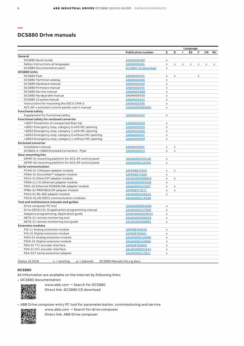
—DCS880 Drive manuals
LanguagePublication number E D I ES F CN RU
GeneralDCS880 Quick Guide 3ADW000480 xSafety instructions all languages 3ADW000481 x x x x x x xDCS880 Documentation pack DCS880 CD download x
DCS880 UnitsDCS880 Flyer 3ADW000475 x x xDCS880 Technical catalog 3ADW000465 xDCS880 Hardware manual 3ADW000462 xDCS880 Firmware manual 3ADW000474 xDCS880 Service manual 3ADW000488 xDCS880 Hardparallel manual 3ADW000530 xDCS880 12-pulse manual 3ADW000533 xInstructions for mounting the SDCS-CMA-2 3ADW000396 xACS-AP-x assistant control panels user’s manual 3AUA0000085685 x
Functional safetySupplement for functional safety 3ADW000452 x
Functional safety for enclosed converter+Q957 Prevention of unexpected Start Up 3ADW000504 x+Q951 Emergency stop, category 0 with MC opening 3ADW000505 x+Q952 Emergency stop, category 1 with MC opening 3ADW000506 x+Q963 Emergency stop, category 0 without MC opening 3ADW000507 x+Q964 Emergency stop, category 1 without MC opening 3ADW000508 x
Enclosed converterInstallation manual 3ADW000091 x xDCS800-A +S880 Enclosed Converters - Flyer 3ADW000523 x x
Door mounting kitsDPMP-01 mounting platform for ACS-AP control panel 3AUA0000100140 xDPMP-02 mounting platform for ACS-AP control panel 3AUA0000136205 x
Serial communicationFCAN-01 CANopen adapter module 3AFE68615500 x xFDNA-01 DeviceNet™ adapter module 3AFE68573360 xFECA-01 EtherCAT adapter module 3AUA0000068940 x xFENA-11/-21 Ethernet adapter module 3AUA0000093568 xFEPL-02 Ethernet POWERLINK adapter module 3AUA0000123527 x xFPBA-01 PROFIBUS DP adapter module 3AFE68573271 x xFSCA-01 RS-485 adapter module 3AUA0000109533 xFDCO-01/02 DDCS communication modules 3AUA0000114058
Tool and maintenance manuals and guidesDrive composer PC tool 3AUA0000094606 xDrive (IEC61131-3) application programming manual 3AUA0000127808 xAdaptive programming, Application guide 3AXD50000028574 xNETA-21 remote monitoring tool 3AUA0000096939 xNETA-21 remote monitoring tool guide 3AUA0000096881 x
Extension modulesFIO-11 Analog extension module 3AFE68784930 xFIO-01 Digital extension module 3AFE68784921 xFAIO-01 Analog extension module 3AUA0000124968 xFDIO-01 Digital extension module 3AUA0000124966 xFEN-01 TTL encoder interface 3AFE68784603 xFEN-31 HTL encoder interface 3AUA0000031044 xFEA-03 F series extension adapter 3AUA0000115811 x
Status 10.2018 x " existing p " planned DCS880 Manuals list e g.docx
DCS880All information are available on the Internet by following links:• DCS880 documentation
www.abb.com " Search for DCS880 Direct link: DCS880 CD download
• ABB Drive composer entry PC tool for parameterization, commissioning and service www.abb.com " Search for drive composer Direct link: ABB Drive composer
6 A B B i n d u s tr i A l d r i v e s D C S 8 8 0 Q u i Ck g u i D e - 3 A DW 0 0 0 4 8 0 R 0 2 016 A B B i n d u s tr i A l d r i v e s D C S 8 8 0 Q u i Ck g u iD e

7D C D r i v e s 7D C D r i v e s
eng
lish
Thyristor Power controller DCT880With the new DCT880 ABB offers its customers a thyristor power controllers for precise control of resistive or inductive heaters and infrared heaters in applications for annealing, drying, melting or heating in glass, plastic or metal industry.
DCS880 DC driveOur DCS880 industrial drives are customized to meet the precise needs of industries such as oil and gas, mining, metals, cement, non motoric, material handling, pulp and paper, rubber and plastics, marine, water and wastewater, food and beverage and automotive. They control a wide range of applications such as cranes, extruders, winches, winders, conveyors, mixers, millstands, centrifuges, test benches, elevators, electrolysis, kiln.

8 A B B i n d u s tr i A l d r i v e s D C S 8 8 0 Q u i Ck g u i D e - 3 A DW 0 0 0 4 8 0 R 0 2 018 A B B i n d u s tr i A l d r i v e s D C S 8 8 0 Q u i Ck g u iD e
Unit 2-Q 4-Q Supply voltage [VAC ] Internal Weight Dimensions
size rated Current rated Current field
DCS880-S01 DCS880-S02 current
IDC [A] IDC [A] 400 500/525 600 690 800 990 1190 [A] [kg] h x w x d [mm] h x w x d [inch]
H1 20 25 6 11 370 x 270 x 215 14.56 x 10.63 x 8.46
45 50 12
65 75 12
90 100 12
H2 135 150 18 16 370 x 270 x 271 14.56 x 10.63 x 10.67
180 200 18
225 250 18
270 300 18
H3 290 320 - 25 460 x 270 x 317 18.11 x 10.63 x 12.48
315 350 25
405 450 25
470 520 25
H4 590 650 - 38 645 x 270 x 352 25.39 x 10.63 x 13.86
610 680 30
740 820 30
900 1000 30
H5 1190 1190 25 ➀ 55 750 x 270 x 372 29.53 x 10.63 x 14.65
H6 900 900 25 ➀ 110 944 x 510 x 410 37.17 x 20.08 x 16.14
1200 1200 25 ➀
1500 1500 25 ➀
2000 25 ➀ 2000 25 ➀
H7 1900 1900 - 180 1750 x 460 x 410 68.90 x 18.11 x 16.14
2050 2050 -
2500 2500 -
3000 3000 -
H8 2050 2050 - 315 1750 x 760 x 570 68.90 x 29.92 x 22.44
2600 2600 -
3300 3300 -
4000 4000 -
4800 4800 -
5200 5200 -
Current ratings, dimensions and weights
—Ratings, types and voltages
H1, H2 H3 H4 H5 H6 H7 H8
➀ FEX-425 Int option

9D C D r i v e s 9D C D r i v e s
eng
lish
Unpacking and examining the delivery
Size H1 … H3 Size H4 Size H5Do not lift the drive by the cover!
BG_DCS_001_verpackung_a.ai
A
A
Mechanical installation
Before installationInstall the drive in an upright position with the cooling section facing a wall. Check the installation site according to the requirements below. Refer to chapter Dimensions and weights in the Hardware manual for frame details.
Cabinet installationThe required distance between parallel units is five millimetres (0.2 in.) in installations without the front cover. The cooling air entering the unit must not exceed +40 °C (+104 °F).
Preventing cooling air recirculation Unit above anotherPrevent air recirculation inside and outside the cabinet.
BG_800_004_luft_b.ai
Hot area
Cool area
Main air flow in
Air baffle plates
Main air flow out
max.+40°C
BG_800_003_luft_a.ai
Air baffle plate
Airflow
Lead the exhaust cooling air away from the unit above.Distances see chapter Dimensions and weights.
—Unpacking and mechanical installation

10 A B B i n d u s tr i A l d r i v e s D C S 8 8 0 Q u i Ck g u i D e - 3 A DW 0 0 0 4 8 0 R 0 2 0110 A B B i n d u s tr i A l d r i v e s D C S 8 8 0 Q u i Ck g u iD e
—Type code and plus codes
The type code contains information on the specification and configuration of the drive. The first digits from left show the basic configuration (e.g. DCS880-S01-2000). The optional selections are given thereafter on the name plate by plus code. The main selections are described below. Not all selections are available for all types.
Type code The drive's basic type code: DCS880-aab-cccc-ddef + plus codeProduct family DCS880Product family aa = S0
= R0= E0= A0
Standard converter moduleRebuild kitPanel solutionEnclosed converter
Bridge type: b = 1= 2
Single bridge (2-Q)2 anti-parallel bridges (4-Q)
Module type: cccc = Rated DC current (IP00)Rated AC voltage: dd = 04
= 05= 06= 07= 08= 10= 12
100 VAC ... 415 VAC
100 VAC ... 525 VAC
270 VAC ... 600 VAC
315 VAC ... 690 VAC
360 VAC ... 800 VAC
450 VAC ... 990 VAC
540 VAC ... 1200 VAC
Power connection: e = X= L= R
Standard H1 ... H7Left side H8Right side H8
Revision code: f = 0 1st generationField exciter configuration: +0S163
+S164H1 ... H4 without OnBoard field exciterH5 and H6 with internal field exciter, supply external (H5 and H6: 25 A, Rebuild kit: 16 A / 25 A)
DCSLink communication +S521 SDCS-DSL-H10 board added (12-pulse, 3-phase fieldexciter)Application programming
+S551 Memory unit including drive application programming license
Plus codesOption Option code Descriptionno ACS-AP-I 0J404 No control panelDPI-H01 +J428 Panel bus daisy-chain optionACS-AP-W +J429 Bluetooth control panelFDNA-01 +K451 Fieldbus DeviceNet FPBA-01 +K454 Fieldbus PROFIBUS FCAN-01 +K457 Fieldbus CANOpen FSCA-01 +K458 Fieldbus Modbus FCNA-01 +K462 Fieldbus ControlNet FECA-01 +K469 Fieldbus EtherCat FEPL-02 +K470 Fieldbus Ethernet POWERLINK FENA-11 +K473 Ethernet/IP, Modbus/TCP, ProfinetFENA-21 +K475 Ethernet/IP, Modbus/TCP, ProfinetFIO-11 +L500 Analog I/O Extension (3 AI, 1 AO, 2 DIO)FIO-01 +L501 Digital I/O Extension (4 DIO, 2 RO)FAIO-01 +L525 Analog I/O Extension (2 AI, 2 AO)FDIO-01 +L526 Digital I/O Extension (3 DI, 2 RO)FEN-01 +L517 TTL Encoder interfaceFEN-21 +L516 Resolver Interface FEN-31 +L502 HTL Encoder Interface FDCO-01 +L503 DDCS communication 10/10 MBd

11D C D r i v e s 11D C D r i v e s
eng
lish
—Brief instructions for virtual CD and documents overview
We appreciate that you purchased an ABB DC drive power converter and thank you for the trust you put in our products.
This brochure was put together to make sure that you continue to be satisfied with our product. It is intended to provide you with a brief overview of the product's key data, EMC notes, typical applications, start-up and trouble-shooting.If you need more information about the product you are provided with a virtual DCS880 CD in addition to this brief documentation. The virtual DCS880 CD is part of this document and features the following contents:
Documentation
Our documentation is basically structured according to the following system:
Technical catalogue (3ADW000465)as comprehensive information to engineer complete DC drive systems.
Hardware manual (3ADW000462)as detailed information, with all important particulars about the individual components, like module dimensions, electronic boards, fans and auxiliary components.Information for mechanical and electrical installation are also included.
Firmware manual (3ADW000474)detailed information with all important issues about firmware and setting of parameters. The manual includes information for start-up and maintenance of the entire drive, in detailed form.This manual also includes Fault and Alarm codes and information for trouble shooting.
Supplement functional safety manual (3ADW000452)detailed technical information about DCS880 STO function and how to handle.
Service manual (3ADW000488)for maintenance and repair of the converters.
ApplicationsDCS880 DC Drive can include application software e.g. magnet control, winders. In such case following procedures and assistants can be blocked or not completed. Please check for further documentation and manuals (check group 7).
Additional information about applications (e.g. 12-pulse) and technical accessories (e.g. Hardware extension or Field bus interfaces) are handled by separate manuals. See table DCS880 Drive manuals.
System requirements to use the virtual DCS880 CD
All manuals of DCS880 and hardware extensions as well as PC tools are collected on a virtual DCS880 CD. The virtual CD can be downloaded from internet by using link DCS880 CD download
• Goto internet search for DCS880 Quick guide (3ADW000480)
• Goto page 6 or use this link• Download CD to PC
Further support
In addition we offer further support, since we can only be satisfied when you, as our customer, are satisfied with us and our products.
InternetOn the ABB homepage under
www.abb.com/dc-drives
you'll find abundant information for • DC products• service support• the latest updates• tools • downloads, etc.Please don't hesitate to visit us.
Register your drive: https://drivereg.drivesapplications.fi/
ContactsIf you require any further information, please contact your nearest ABB Drives office or send an email to:
Please give us your name, your company address and phone number. We immediately put you in contact with our specialist.
Technical data and specifications are valid as of going to press. ABB reserves the right to make subsequent alterations.
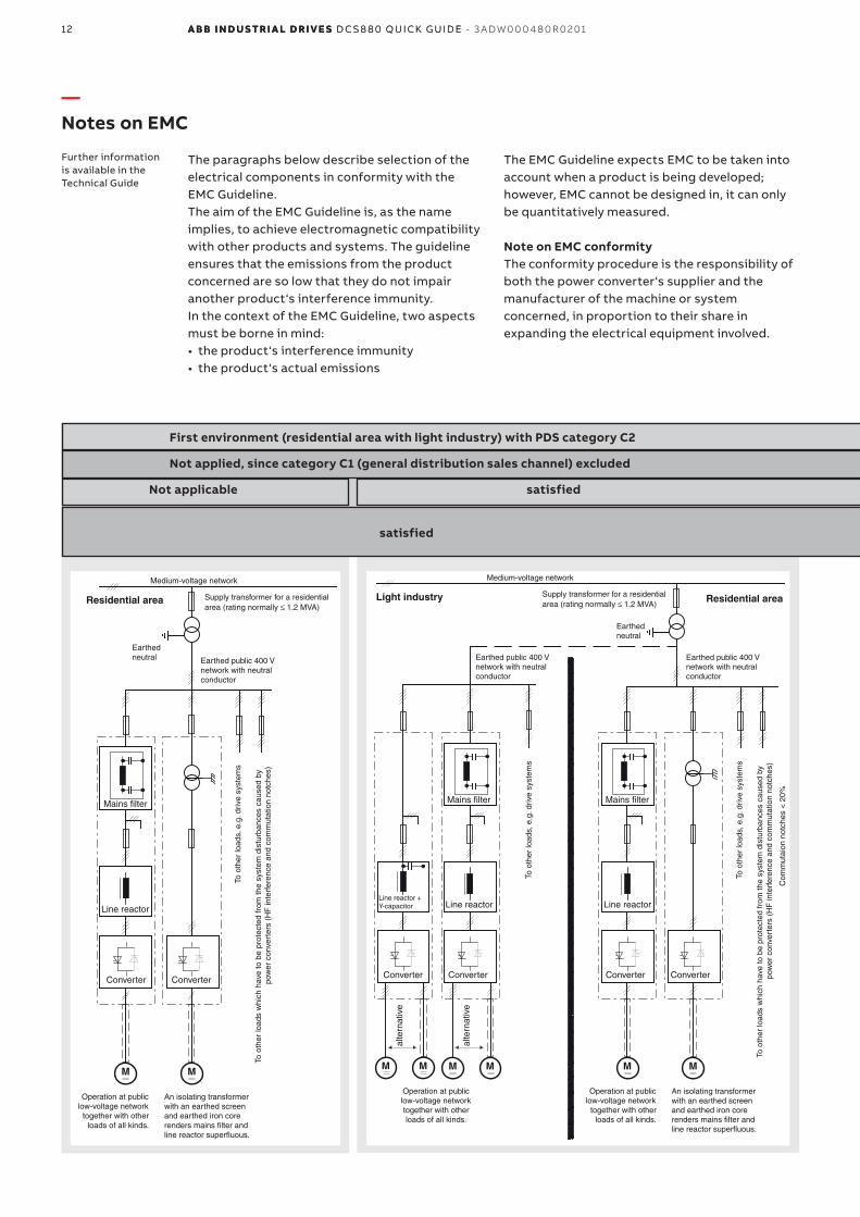
—Notes on EMC
Further information is available in the Technical Guide
The paragraphs below describe selection of the electrical components in conformity with the EMC Guideline. The aim of the EMC Guideline is, as the name implies, to achieve electromagnetic compatibility with other products and systems. The guideline ensures that the emissions from the product concerned are so low that they do not impair another product‘s interference immunity. In the context of the EMC Guideline, two aspects must be borne in mind:• the product‘s interference immunity• the product‘s actual emissions
The EMC Guideline expects EMC to be taken into account when a product is being developed; however, EMC cannot be designed in, it can only be quantitatively measured.
Note on EMC conformityThe conformity procedure is the responsibility of both the power converter‘s supplier and the manufacturer of the machine or system concerned, in proportion to their share in expanding the electrical equipment involved.
Not applicable
satisfied satisfied
satisfied satisfied
Not applied, since category C1 (general distribution sales channel) excluded Not applicable
First environment (residential area with light industry) with PDS category C2 Second environment (industry) with PDS categories C3, C4
MM MMMM MM
Mains filter
Converter
Line reactor
Supply transformer for a residential area (rating normally ≤ 1.2 MVA)
Earthed public 400 V network with neutral conductor
Medium-voltage network
Earthed neutral
Legend
Unscreened cable with restriction
Screened cable
To o
ther
load
s, e
.g. d
rive
syst
ems
An isolating transformer with an earthed screen and earthed iron core renders mains filter and line reactor superfluous.
Operation at public low-voltage network
together with other loads of all kinds.
alte
rnat
ive
alte
rnat
ive
Line reactor + Y-capacitor
Residential area
To o
ther
load
s w
hich
hav
e to
be
prot
ecte
d fr
om th
e sy
stem
dis
turb
ance
s ca
used
by
pow
er c
onve
rter
s (H
F in
terf
eren
ce a
nd c
omm
utat
ion
notc
hes)
Converter
Medium-voltage network
Supply transformer for a residential
Earthed neutral
Earthed public 400 V network with neutral conductor
To o
ther
load
s, e
.g. d
rive
syst
ems
Mains filter
Line reactor
Converter Converter
Mains filter
Line reactor
Converter Converter
An isolating transformer with an earthed screen and earthed iron core renders mains filter and line reactor superfluous.
Operation at public low-voltage network
together with other loads of all kinds.
To o
ther
load
s, e
.g. d
rive
syst
ems
To o
ther
load
s w
hich
hav
e to
be
prot
ecte
d fr
om th
e sy
stem
dis
turb
ance
s ca
used
by
pow
er c
onve
rter
s (H
F in
terf
eren
ce a
nd c
omm
utat
ion
notc
hes)
Earthed public 400 V network with neutral conductor
Operation at public low-voltage network together with other loads of all kinds.
Light industry Residential area
Com
mut
aion
not
ches
< 2
0%
area (rating normally 1.2 MVA)
MM MMMM MM
Mains filter
Converter
Line reactor
Supply transformer for a residential area (rating normally ≤ 1.2 MVA)
Earthed public 400 V network with neutral conductor
Medium-voltage network
Earthed neutral
Legend
Unscreened cable with restriction
Screened cable
To o
ther
load
s, e
.g. d
rive
syst
ems
An isolating transformer with an earthed screen and earthed iron core renders mains filter and line reactor superfluous.
Operation at public low-voltage network
together with other loads of all kinds.
alte
rnat
ive
alte
rnat
ive
Line reactor + Y-capacitor
Residential area
To o
ther
load
s w
hich
hav
e to
be
prot
ecte
d fr
om th
e sy
stem
dis
turb
ance
s ca
used
by
pow
er c
onve
rter
s (H
F in
terf
eren
ce a
nd c
omm
utat
ion
notc
hes)
Converter
Medium-voltage network
Supply transformer for a residential
Earthed neutral
Earthed public 400 V network with neutral conductor
To o
ther
load
s, e
.g. d
rive
syst
ems
Mains filter
Line reactor
Converter Converter
Mains filter
Line reactor
Converter Converter
An isolating transformer with an earthed screen and earthed iron core renders mains filter and line reactor superfluous.
Operation at public low-voltage network
together with other loads of all kinds.
To o
ther
load
s, e
.g. d
rive
syst
ems
To o
ther
load
s w
hich
hav
e to
be
prot
ecte
d fr
om th
e sy
stem
dis
turb
ance
s ca
used
by
pow
er c
onve
rter
s (H
F in
terf
eren
ce a
nd c
omm
utat
ion
notc
hes)
Earthed public 400 V network with neutral conductor
Operation at public low-voltage network together with other loads of all kinds.
Light industry Residential area
Com
mut
aion
not
ches
< 2
0%
area (rating normally ≤ 1.2 MVA)
12 A B B i n d u s tr i A l d r i v e s D C S 8 8 0 Q u i Ck g u i D e - 3 A DW 0 0 0 4 8 0 R 0 2 0112 A B B i n d u s tr i A l d r i v e s D C S 8 8 0 Q u i Ck g u iD e
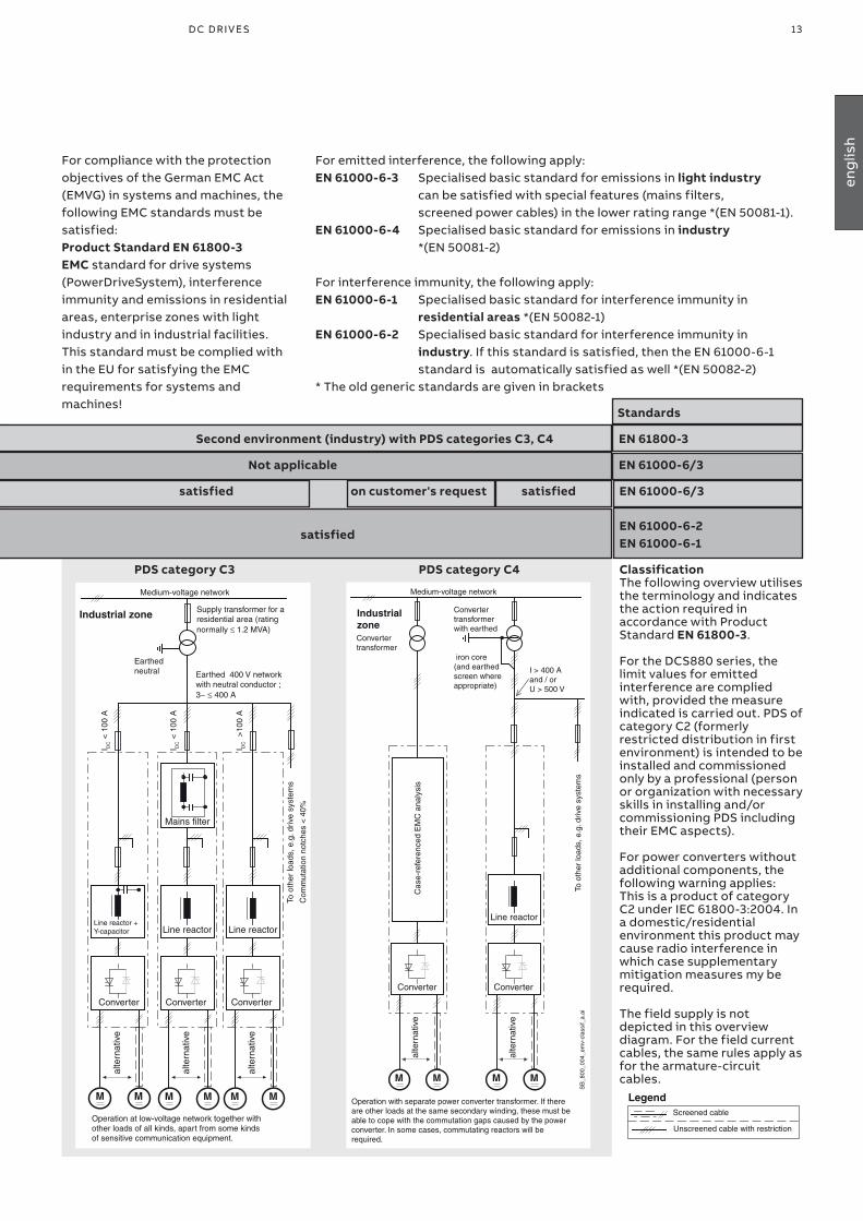
For compliance with the protection objectives of the German EMC Act (EMVG) in systems and machines, the following EMC standards must be satisfied:Product Standard EN 61800-3EMC standard for drive systems (PowerDriveSystem), interference immunity and emissions in residential areas, enterprise zones with light industry and in industrial facilities. This standard must be complied with in the EU for satisfying the EMC requirements for systems and machines!
For emitted interference, the following apply: EN 61000-6-3 Specialised basic standard for emissions in light industry can be satisfied with special features (mains filters, screened power cables) in the lower rating range *(EN 50081-1). EN 61000-6-4 Specialised basic standard for emissions in industry *(EN 50081-2)
For interference immunity, the following apply: EN 61000-6-1 Specialised basic standard for interference immunity in residential areas *(EN 50082-1) EN 61000-6-2 Specialised basic standard for interference immunity in industry. If this standard is satisfied, then the EN 61000-6-1 standard is automatically satisfied as well *(EN 50082-2) * The old generic standards are given in brackets
satisfied satisfied
on customer's request satisfied
PDS category C3 PDS category C4
EN 61800-3
Standards
EN 61000-6/3
EN 61000-6/3
EN 61000-6-2EN 61000-6-1
satisfied satisfied
Not applied, since category C1 (general distribution sales channel) excluded Not applicable
First environment (residential area with light industry) with PDS category C2 Second environment (industry) with PDS categories C3, C4
MMMM MMMMMM
SB
_800
_004
_em
v-cl
assi
f_a.
ai
I DC <
100
A
I DC <
100
A
I DC >
100
A
Supply transformer for a residential area (rating normally ≤ 1.2 MVA)
Earthed 400 V network with neutral conductor ; 3~ ≤ 400 A
Convertertransformer
Cas
e-re
fere
nced
EM
C a
naly
sis
alte
rnat
ive
Converter transformer with earthed
iron core (and earthed screen where appropriate)
alte
rnat
ive
I > 400 A and / or U > 500 V
Operation at low-voltage network together with other loads of all kinds, apart from some kinds of sensitive communication equipment.
Operation with separate power converter transformer. If there are other loads at the same secondary winding, these must be able to cope with the commutation gaps caused by the power converter. In some cases, commutating reactors will be required.
To o
ther
load
s, e
.g. d
rive
syst
ems
Line reactor + Y-capacitor Line reactor
Converter Converter
Mains filter
Earthed neutral
Medium-voltage networkTo
oth
er lo
ads,
e.g
. driv
e sy
stem
s
Converter Converter
Line reactor
Medium-voltage network
Industrial zone Industrial zone
alte
rnat
ive
alte
rnat
ive
Line reactor
Converter
alte
rnat
ive
Com
mut
atio
n no
tche
s <
40%
MMMM MMMMMM
SB
_800
_004
_em
v-cl
assi
f_a.
ai
I DC <
100
A
I DC <
100
A
I DC >
100
A
Supply transformer for a residential area (rating normally ≤ 1.2 MVA)
Earthed 400 V network with neutral conductor ; 3~ ≤ 400 A
Convertertransformer
Cas
e-re
fere
nced
EM
C a
naly
sis
alte
rnat
ive
Converter transformer with earthed
iron core (and earthed screen where appropriate)
alte
rnat
ive
I > 400 A and / or U > 500 V
Operation at low-voltage network together with other loads of all kinds, apart from some kinds of sensitive communication equipment.
Operation with separate power converter transformer. If there are other loads at the same secondary winding, these must be able to cope with the commutation gaps caused by the power converter. In some cases, commutating reactors will be required.
To o
ther
load
s, e
.g. d
rive
syst
ems
Line reactor + Y-capacitor Line reactor
Converter Converter
Mains filter
Earthed neutral
Medium-voltage network
To o
ther
load
s, e
.g. d
rive
syst
ems
Converter Converter
Line reactor
Medium-voltage network
Industrial zone Industrial zone
alte
rnat
ive
alte
rnat
ive
Line reactor
Converter
alte
rnat
ive
Com
mut
atio
n no
tche
s <
40%
ClassificationThe following overview utilises the terminology and indicates the action required in accordance with Product Standard EN 61800-3. For the DCS880 series, the limit values for emitted interference are complied with, provided the measure indicated is carried out. PDS of category C2 (formerly restricted distribution in first environment) is intended to be installed and commissioned only by a professional (person or organization with necessary skills in installing and/or commissioning PDS including their EMC aspects).
For power converters without additional components, the following warning applies: This is a product of category C2 under IEC 61800-3:2004. In a domestic/residential environment this product may cause radio interference in which case supplementary mitigation measures my be required. The field supply is not depicted in this overview diagram. For the field current cables, the same rules apply as for the armature-circuit cables.
MM MMMM MM
Mains filter
Converter
Line reactor
Supply transformer for a residential area (rating normally ≤ 1.2 MVA)
Earthed public 400 V network with neutral conductor
Medium-voltage network
Earthed neutral
Legend
Unscreened cable with restriction
Screened cable
To o
ther
load
s, e
.g. d
rive
syst
ems
An isolating transformer with an earthed screen and earthed iron core renders mains filter and line reactor superfluous.
Operation at public low-voltage network
together with other loads of all kinds.
alte
rnat
ive
alte
rnat
ive
Line reactor + Y-capacitor
Residential area
To o
ther
load
s w
hich
hav
e to
be
prot
ecte
d fr
om th
e sy
stem
dis
turb
ance
s ca
used
by
pow
er c
onve
rter
s (H
F in
terf
eren
ce a
nd c
omm
utat
ion
notc
hes)
Converter
Medium-voltage network
Supply transformer for a residential
Earthed neutral
Earthed public 400 V network with neutral conductor
To o
ther
load
s, e
.g. d
rive
syst
ems
Mains filter
Line reactor
Converter Converter
Mains filter
Line reactor
Converter Converter
An isolating transformer with an earthed screen and earthed iron core renders mains filter and line reactor superfluous.
Operation at public low-voltage network
together with other loads of all kinds.
To o
ther
load
s, e
.g. d
rive
syst
ems
To o
ther
load
s w
hich
hav
e to
be
prot
ecte
d fr
om th
e sy
stem
dis
turb
ance
s ca
used
by
pow
er c
onve
rter
s (H
F in
terf
eren
ce a
nd c
omm
utat
ion
notc
hes)
Earthed public 400 V network with neutral conductor
Operation at public low-voltage network together with other loads of all kinds.
Light industry Residential area
Com
mut
aion
not
ches
< 2
0%
area (rating normally 1.2 MVA)
13D C D r i v e s 13D C D r i v e s
eng
lish
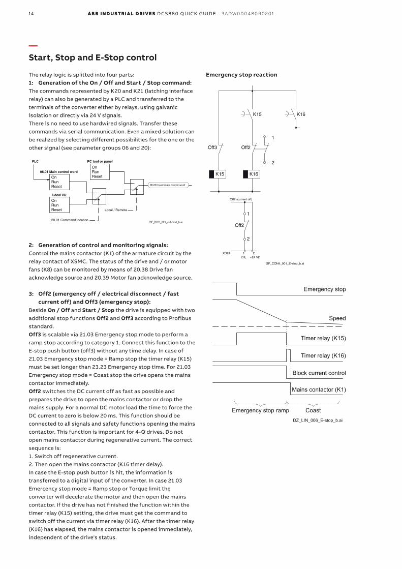
—Start, Stop and E-Stop control
The relay logic is splitted into four parts:1: Generation of the On / Off and Start / Stop command:The commands represented by K20 and K21 (latching interface relay) can also be generated by a PLC and transferred to the terminals of the converter either by relays, using galvanic isolation or directly via 24 V signals. There is no need to use hardwired signals. Transfer these commands via serial communication. Even a mixed solution can be realized by selecting different possibilities for the one or the other signal (see parameter groups 06 and 20):
06.01 Main control word
SF_DCS_001_ctrl-cmd_b.ai
06.09 Used main control word
Local I/O
20.01 Command location
PC tool or panel
Local / Remote
OnRunReset
On
OnRun
Reset
ResetRun
PLC
2: Generation of control and monitoring signals: Control the mains contactor (K1) of the armature circuit by the relay contact of XSMC. The status of the drive and / or motor fans (K8) can be monitored by means of 20.38 Drive fan acknowledge source and 20.39 Motor fan acknowledge source. 3: Off2 (emergency off / electrical disconnect / fast current off) and Off3 (emergency stop):Beside On / Off and Start / Stop the drive is equipped with two additional stop functions Off2 and Off3 according to Profibus standard. Off3 is scalable via 21.03 Emergency stop mode to perform a ramp stop according to category 1. Connect this function to the E-stop push button (off3) without any time delay. In case of 21.03 Emergency stop mode = Ramp stop the timer relay (K15) must be set longer than 23.23 Emergency stop time. For 21.03 Emergency stop mode = Coast stop the drive opens the mains contactor immediately.Off2 switches the DC current off as fast as possible and prepares the drive to open the mains contactor or drop the mains supply. For a normal DC motor load the time to force the DC current to zero is below 20 ms. This function should be connected to all signals and safety functions opening the mains contactor. This function is important for 4-Q drives. Do not open mains contactor during regenerative current. The correct sequence is:1. Switch off regenerative current.2. Then open the mains contactor (K16 timer delay).In case the E-stop push button is hit, the information is transferred to a digital input of the converter. In case 21.03 Emercency stop mode = Ramp stop or Torque limit the converter will decelerate the motor and then open the mains contactor. If the drive has not finished the function within the timer relay (K15) setting, the drive must get the command to switch off the current via timer relay (K16). After the timer relay (K16) has elapsed, the mains contactor is opened immediately, independent of the drive's status.
Emergency stop reaction
K16K15
K15
1
2
SF_CON4_001_E-stop_b.ai
1
2
K16
Off2
Off2
Off2 (current off)
1DIL
XD24 2+24 VD
Off3
DZ_LIN_006_E-stop_b.ai
Emergency stop
Speed
Block current control
Mains contactor (K1)
Emergency stop ramp Coast
Timer relay (K15)
Timer relay (K16)
14 A B B i n d u s tr i A l d r i v e s D C S 8 8 0 Q u i Ck g u i D e - 3 A DW 0 0 0 4 8 0 R 0 2 0114 A B B i n d u s tr i A l d r i v e s D C S 8 8 0 Q u i Ck g u iD e

15D C D r i v e s 15D C D r i v e s
eng
lish
—Planning the electrical installation, size H1 ... H5
Converters size H1 ... H5 configuration using an OnBoard field exciter Wiring the drive according to this diagram offers the highest degree of monitoring functions done by the drive.
XTA
C
+
-
L1
M
T
+ _
E
F2
K1
Klix
on
K21
K20
K1
T269
0 V
660
V60
0 V
575
V52
5 V
500
V45
0 V
415
V40
0 V
380
V
115
V
230
V
K16
K16
K8
XS
MC
:1
XS
MC
:2X
SM
C:3
XS
MC
:4
XR
O3
= Fa
n on
K21
32 33
K20
F7F2
1 2
Sto
p
Sta
rt
SD
CS
-CO
N-H
01J6
AI1
- J1
AI2
- J2
AO
1 - J
5
SF_
880_
020_
DC
S_a
nsch
luss
_e.a
i
D2D
- J3
curr
ent 2
0 m
A
volta
ge 1
0 V
de
faul
t
defa
ult
defa
ult
defa
ult
open
term
inat
edop
encl
osed
defa
ult
Slot3
Slot2
Slot1
Control panel
DCSLink
Mainscontactor
Latching on
Latching run
On
Run
Reset
Off2 (current off)
OUT1
SGND
IN1
IN2
NC
COM
NO
NC
COM
NO
NC
COM
NO
COM
NO
COM
NO
B
A
BGND
DI1
DI2
DIO1
DIO2
DI3
DI4
DI5
DI6
+10V-10V
AGND
AI1-
AI2+
AI2-
AI1+
DICOM
+24VD
DIOGND
+24VD
DIL
AO2
AGND
AGND
AO1
AI3-
AI3+
1
2
3
4X
RO
1
XS
MC
1211
2221
2313
34
21
XR
O2
X13
X20
0
3231
33X
RO
3X
STO
XD
IO1
XD
2D1
32
XA
I1
23
45
67
XD
I1
23
45
62
XA
O1
23
4
IACT 5
XD
241
23
45
89
OnB
oard
ta
cho
feed
back
OnB
oard
Enc
oder
Fee
dbac
k
U1
V1
W1
D1
C1
1
2X
AU
X (X
99)
3 4K
1
L1L2
L3
F1
15
26
Pow
er
supp
ly
F51 2
1
max
.±2
70 V
7E
GN
D
24 V
5 V
8
J4D
1
2
3
4
5
62
XE
NC
+ A
-+
B -
+ Z
-
1 2
OFF
2
OFF
2
1 2K
21K
20K
8
On
Off
E1EM
V-Fi
lter
Aux
sup
ply
Mai
ns
L1L2
3 4
1 2
F
or p
rope
r fee
dbac
k se
t 10.
24 R
01 s
ourc
e =
31.9
1.b7
or 3
1.98
.b11
3 4K
3
F3
15
26
L3
E
xcita
tion
supp
ly s
ize
H5
F
EX
-425
-Int o
ptio
n, o
nBoa
rd e
xcita
tion
H1
... H
4
1 2K
8F8
1 2
1 2
H4,
H5
F100
... F
102
Fiel
d ex
cite
rX
10: F
+F-
Fans on
H
4 an
d H
5 on
ly
Fan acknowledge S
DC
S-P
IN-H
01
PE
J4 A
B
CJ4 D
E
ncod
ersu
pply
10 kΩ
24 V
5 V
120 Ω
pull
up
diffe
rent
ial
Res
et
Saf
ety
Rel
ais
Sam
ple
circ
uit E
-STO
P C
at 0
with
DC
S88
0 S
TO
S1A
4
Attention: Do not forget to mount the cable shield grounding plate from the accessary pack:
Example for DC main terminal cover for H4 converter modules.
⑥ H4 fan connection
M
PIN-H0124 V internal
PIN-H0124 V internal
MM55 M56
M MM55 M56
M MM57 M58
M55M~
1 2 3 4 5X52:
L N
L N
J
SA_880_011_DCS_FAN_c.ai
M_ _ _ _ _
_ _
X41: 1 2 X41: 1 2 X42: 1 2 X41: 1 2 X43: 1 2 X42: 1 2 X44: 1 2
PIN-H0124 V internal
M55
+ - + - + - + - + - + - + -
⑥ H5 fan connection
U1 V1 W1 U2 V2 W2 TK TKPE
at
U1-W2V1-U2W1-V2
M~J
U1 V1 W1U2 V2W2PE TB TB
at
M~
U1 V1 W1U2 V2W2PE TB TB
at
U2 - V2 - W2
M~
U1-W2V1-U2W1-V2
M~
2 31X2: 4 5
L N
SA_880_011_DCS_FAN_b.ai
Connection
Connection
Connection
⑥

16 A B B i n d u s tr i A l d r i v e s D C S 8 8 0 Q u i Ck g u i D e - 3 A DW 0 0 0 4 8 0 R 0 2 0116 A B B i n d u s tr i A l d r i v e s D C S 8 8 0 Q u i Ck g u iD e
—Terminal locations of the converter
Ch.
A+
Ch.
A-
Ch.
B+
Ch.
B-
Ch.
Z+
Ch.
Z-
GN
D+5
V o
r +2
4V DI1
DI2
DI3
DI4
DI5
DI6
CO
M NO
CO
M NO
OU
T1SG
ND
IN1
IN2
DIL
+24V
DD
ICO
M+2
4VD
DIO
GN
D
DO
1
DO
2
1 2 3 4 5 6 7 8 9 1 2 3 4 5
+10
V-1
0V
AG
ND
AI1
-A
I1+
AI2
-A
I2+
AI3
-A
I3+
AO
1+1
0V
-10
VG
ND
24V
0V
GN
DB
CA
NL
CA
NH
GN
DB
CA
NL
CA
NH
AO
1
11 12 13
NC
CO
MN
O
21 22 23
NC
CO
MN
O
31 32 33
NC
CO
MN
O
2 3B A
BG
ND
1 2 3 4 5 6 7 8 1 2 3 4 5 61 2 3 4 1 2 3 4 1 2 1 2 3 4 5 1
XDI XAIXSMC XSTO XRO1 XRO2 XRO3XD2DXAO
SDCS-DSL-Hxx
XENC (Encoder) XD24XDO
F100 F101 F102
C1 U1 V1 W1 D1
F+ F-
X10:
max 230 V
(H5) X2:(H4) X52:
5 1
BL_CONH01_002_allocation_b.ai
X51
1 2 1 2 3 1 2 3
X52 X53
X200
J1ON
XSMC XTAC
X13
PANEL
X205MEMORY
UNIT
V301
X208
X38
X12
X14
XC
12X
C13
XS1
3
OPTION
X200
1
3
4
6
DCSLinkOPTION XRO1
XRO2
XRO3XENC
cable shield grounding plate
J4XSTO XDI XDIO
J3J6
J5J1
XD24
XD2DXAOXAI J2J7
CONTROLSLOT1 Battery
SLOT2
FAN
SAFETY
SLOT3
DCS880 module: Terminal allocation
Aux.supply
Fan
SDCS-CON-H: Connector allocation
SDCS-CON-H: Terminal allocation
DCS880 Accessories
Cross section areas - Thightening torquesRecommended cross-sectional area to DINVDE 0276-1000 and DINVDE 0100-540 (PE) trefoil arrangement, up to 50°C ambient temperature. Armature:
Converter type C1, D1 U1, V1, W1 PEIDC
[A-]1
[mm²](2.)
[mm²] Iv
[A~] [mm²] [mm²] [Nm]
DCS880-S0x-0025-xx 25 1 x 6 - 21 1 x 4 1 x 10 1 x M6 6DCS880-S0x-0050-xx 50 1 x 10 - 41 1 x 6 1 x 10 1 x M6 6DCS880-S0x-0075-xx 75 1 x 25 - 61 1 x 25 1 x 16 1 x M6 6DCS880-S0x-0100-xx 100 1 x 25 - 82 1 x 25 1 x 16 1 x M6 6DCS880-S0x-0150-xx 150 1 x 35 - 114 1 x 35 1 x 16 1 x M10 25DCS880-S0x-0200-xx 200 2 x 35 1 x 95 163 2 x 25 1 x 25 1 x M10 25DCS880-S0x-0250-xx 250 2 x 35 1 x 95 204 2 x 25 1 x 25 1 x M10 25DCS880-S0x-0300-xx 300 2 x 70 1 x 95 220 2 x 50 1 x 50 1 x M10 25DCS880-S0x-0320-xx 320 2 x 70 1 x 95 220 2 x 50 1 x 50 1 x M10 25DCS880-S0x-0350-xx 350 2 x 70 - 286 2 x 50 1 x 50 1 x M10 25DCS880-S0x-0450-xx 450 2 x 95 - 367 2 x 95 1 x 95 1 x M10 25DCS880-S0x-0520-xx 520 2 x 95 - 424 2 x 95 1 x 95 1 x M10 25DCS880-S0x-0650-xx 650 2 x 120 - 555 2 x 120 1 x 120 1 x M12 50DCS880-S0x-0680-xx 680 2 x 120 - 555 2 x 120 1 x 120 1 x M12 50DCS880-S0x-0820-xx 820 2 x 150 - 669 2 x 120 1 x 120 1 x M12 50DCS880-S0x-0900-6/7 900 4 x 95 3 x 150 734 4 x 70 1 x 150 2 x M12 50DCS880-S0x-1000-xx 1000 2 x 185 - 816 2 x 150 1 x 150 1 x M12 50DCS880-S0x-1190-xx 1190 4 x 120 - 971 4 x 95 2 x 95 2 x M12 50
You will find instructions on how to calculate the PE conductor’s cross-sectional area in VDE 0100 or in equivalent national standards. We would remind you that power converters may have a current-limiting effect.
Excitation:
Size H1 H1 H2 H3, H5, H6 H4 H5DC output current 6 A 12 A 18 A 25 A 30 Amax. cross sectional area 6 mm²/ AWG 10 6 mm²/ AWG 10 6 mm²/ AWG 10 6 mm²/ AWG 10 6 mm²/ AWG 10min. cross sectional area 1 mm²/ AWG 16 2.5 mm²/ AWG 13 4 mm²/ AWG 11 6 mm²/ AWG 10 6 mm²/ AWG 10Tightening torque 1.5 ... 1.7 Nm
cable shield grounding plate
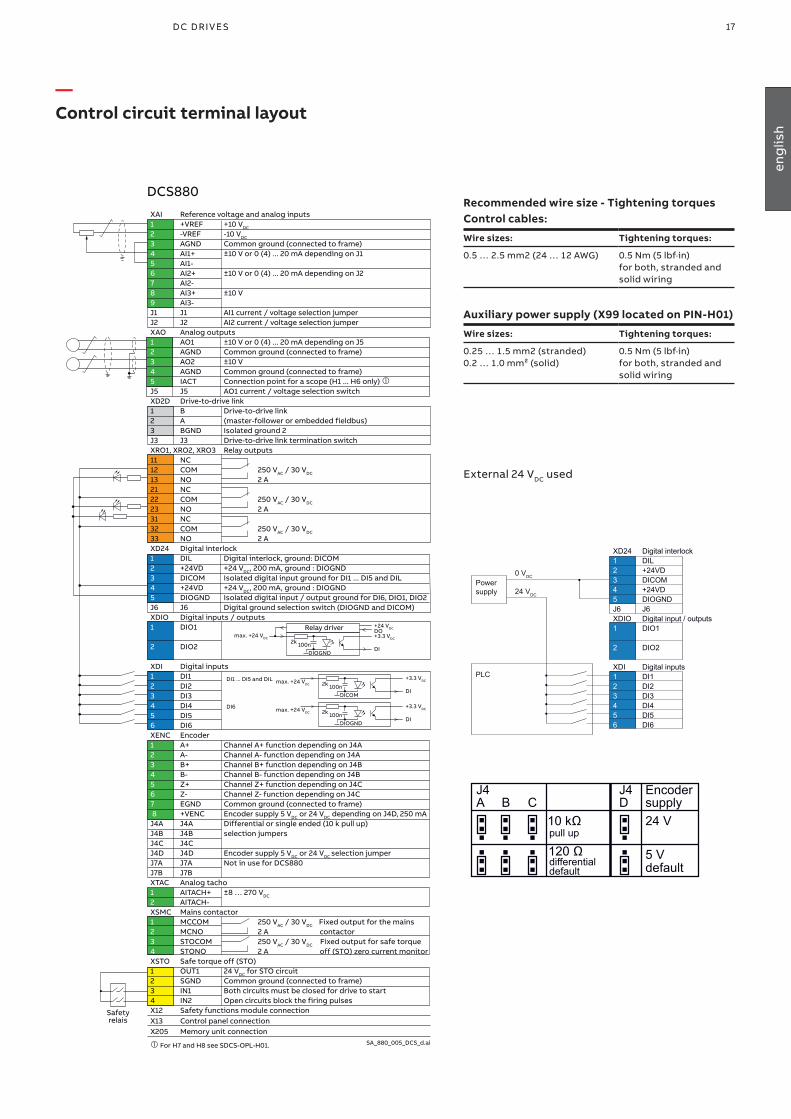
17D C D r i v e s 17D C D r i v e s
eng
lish
—Control circuit terminal layout
Relay driver
2k
+24 VDC
+3.3 VDCmax. +24 VDC
DO
DI100n
DIOGND
2k+3.3 VDCmax. +24 VDC
DI1 ... DI5 and DIL
DI100n
DICOM
2k+3.3 VDCmax. +24 VDC
DI6
DI100n
DIOGND
XAI Reference voltage and analog inputs1 +VREF +10 VDC
2 -VREF -10 VDC
3 AGND Common ground (connected to frame)4 AI1+ ±10 V or 0 (4) ... 20 mA depending on J15 AI1- 6 AI2+ ±10 V or 0 (4) ... 20 mA depending on J27 AI2-8 AI3+ ±10 V 9 AI3- J1 J1 AI1 current / voltage selection jumperJ2 J2 AI2 current / voltage selection jumperXAO Analog outputs 1 AO1 ±10 V or 0 (4) ... 20 mA depending on J52 AGND Common ground (connected to frame)3 AO2 ±10 V4 AGND Common ground (connected to frame)5 IACT Connection point for a scope (H1 ... H6 only) J5 J5 AO1 current / voltage selection switch XD2D Drive-to-drive link 1 B Drive-to-drive link 2 A (master-follower or embedded fieldbus) 3 BGND Isolated ground 2J3 J3 Drive-to-drive link termination switchXRO1, XRO2, XRO3 Relay outputs 11 NC 12 COM 250 VAC / 30 VDC
13 NO 2 A21 NC 22 COM 250 VAC / 30 VDC
23 NO 2 A31 NC 32 COM 250 VAC / 30 VDC
33 NO 2 AXD24 Digital interlock 1 DIL Digital interlock, ground: DICOM2 +24VD +24 VDC, 200 mA, ground : DIOGND 3 DICOM Isolated digital input ground for DI1 ... DI5 and DIL4 +24VD +24 VDC, 200 mA, ground : DIOGND 5 DIOGND Isolated digital input / output ground for DI6, DIO1, DIO2J6 J6 Digital ground selection switch (DIOGND and DICOM)XDIO Digital inputs / outputs 1 DIO1 2 DIO2 XDI Digital inputs 1 DI1 2 DI2 3 DI3 4 DI4 5 DI5 6 DI6 XENC Encoder1 A+ Channel A+ function depending on J4A 2 A- Channel A- function depending on J4A 3 B+ Channel B+ function depending on J4B 4 B- Channel B- function depending on J4B 5 Z+ Channel Z+ function depending on J4C 6 Z- Channel Z- function depending on J4C 7 EGND Common ground (connected to frame) 8 +VENC Encoder supply 5 VDC or 24 VDC depending on J4D, 250 mA J4A J4A Differential or single ended (10 k pull up) J4B J4B selection jumpers J4C J4C J4D J4D Encoder supply 5 VDC or 24 VDC selection jumperJ7A J7A Not in use for DCS880J7B J7B XTAC Analog tacho1 AITACH+ ±8 … 270 VDC
2 AITACH- XSMC Mains contactor 1 MCCOM 250 VAC / 30 VDC Fixed output for the mains2 MCNO 2 A contactor3 STOCOM 250 VAC / 30 VDC Fixed output for safe torque 4 STONO 2 A off (STO) zero current monitorXSTO Safe torque off (STO)1 OUT1 24 VDC for STO circuit2 SGND Common ground (connected to frame) 3 IN1 Both circuits must be closed for drive to start 4 IN2 Open circuits block the firing pulsesX12 Safety functions module connection X13 Control panel connection X205 Memory unit connection
For H7 and H8 see SDCS-OPL-H01. SA_880_005_DCS_d.ai
DCS880
Safetyrelais
Recommended wire size - Tightening torquesControl cables:
Wire sizes: Tightening torques:
0.5 … 2.5 mm2 (24 … 12 AWG) 0.5 Nm (5 lbf·in) for both, stranded and solid wiring
Auxiliary power supply (X99 located on PIN-H01)
Wire sizes: Tightening torques:
0.25 … 1.5 mm2 (stranded)0.2 … 1.0 mm² (solid)
0.5 Nm (5 lbf·in) for both, stranded and solid wiring
External 24 VDC used
XD24 Digital interlock 1 DIL 2 +24VD 3 DICOM 4 +24VD 5 DIOGND J6 J6 XDIO Digital input / outputs 1 DIO1
2 DIO2
XDI Digital inputs 1 DI1 2 DI2 3 DI3 4 DI4 5 DI5 6 DI6
Powersupply
PLC
0 VDC
24 VDC
SA_880_010_DCT-PLC_a.ai
defaultdefault
J4A B C
J4D
Encodersupply
10 kΩ 24 V
5 V120 Ωpull up
differential

18 A B B i n d u s tr i A l d r i v e s D C S 8 8 0 Q u i Ck g u i D e - 3 A DW 0 0 0 4 8 0 R 0 2 0118 A B B i n d u s tr i A l d r i v e s D C S 8 8 0 Q u i Ck g u iD e
—Notes For North American Installations
1. EMC conformity is not usually required in North America. In most cases, the section “Notes on EMC” can be bypassed. In this manual, you will see references to DIN, EN and VDE standards. These are European standards and, generally, do not apply to North America. It is, however, the responsibility of the user to determine which standards need to be followed.
2. If using a DC contactor, you must connect an auxiliary contact to a digital input of your choice and set para. MainContAck accordingly. Set the following parameters:
20.34 Mains contactor acknowledge source =DI6 (or any input you choose for the DC cont. auxiliary contact)
10.24 RO1 source = Close US style DC-Contactor 04.24b10
20.33 Mains contactor control mode = DCcontact (3)95.37 DC voltage measurement mode = See table below
Set these parameters AFTER macros are loaded but BEFORE the drive is commissioned.Relay out 1 (XRO1) must be used to turn the DC contactor on and off.
DZ_LIN_007_us_c.ai
Main contactor 06.24.b07
Dynamic braking 06.24.b08
US style DC contactor 06.24.b10
t
SF_880_039_measurement_a.ai
FirmwareInternal DC voltagemeasurement
DCS880
US K1.1
C1
RB
D1
H1 ... H8Internal DC voltage measurement
M
95.37 DC voltage measurement mode = DC contactor
3. If using Dynamic Braking, the drive allows you to select the stopping method under three different situations. Parameters 21.02, 21.03 and 21.04 select the stopping method for loss of the OnOff, run command (StartStop, Jog1, Jog2, etc.), and E-Stop input, respectively.
Each can be set to:• Coast stop• Ramp stop In order to command the drive to perform a DB stop, one or more of these parameters must be set to DynBraking. Most users will want the drive to ramp stop when OnOff or a run command (StartStop, Jog1, Jog2, etc.) input is cleared, and dynamically brake when the E-Stop input is cleared. In that case, use the following settings:• 21.02 Off1 mode = Ramp stop• 21.04 Stop mode = Ramp stop• 21.03 Emergency stop mode = Dynamic braking However, any case is allowed and the final decision is left to the user.Other parameters control stops during faults. See:• 31.13 Fault stop mode communication• 31.14 Stop mode trip level 3• 31.15 Stop mode trip level 4
If using EMF feedback with dynamic braking, set:• 20.44 Dynamic braking delay = tWhere: t = The time (sec) it normally takes the motor to stop during dynamic braking
External motor voltage measurementIn case field weakening is used, external DC voltage measurement at the motor terminals is mandatory. External DC voltage measurement for sizes H1 ... H5 can be made using a SDCS-UCM-01 or a DC-DC transducer. Sizes H6 ... H8 internal DC voltage measurement cables can be rewired to the motor terminals.
95.37 DC voltage measurement mode = AI3 scaled
Internal ExternalDC volt measurement DC volt measurement
H1 ... H5 via AI3 H6 ... H8 re-wire
20.33 Mains contactor control mode
DC contactor On
95.37 DC voltage measurement mode
DC contactor H1 ... H5 = AI3H6 ... H8 = Manual
SF_880_039_measurement_a.ai
DCS880
SDCS-UCM-01
C1
D1
H1 ... H5External DC voltage measurement
A13
FirmwareExternal DC voltagemeasurement
RB
M
US K1.1
DC contactor US:DC contactor US K1.1 is a special designed contactor with 2 x NO contacts for C1 and D1 connection and 1 x NC contact for connection of Dynamic Brake resistor RB.The contactor should be controlled by signal 6.24 bit 10.The acknowledge can be connected to parameter: 20.34 Main contactor acknowledge
• Torque limit• Dynamic braking
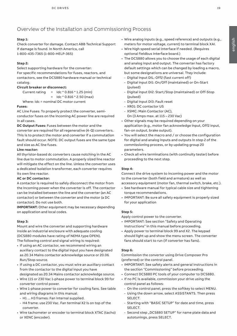
19D C D r i v e s 19D C D r i v e s
eng
lish
Overview of the Installation and Commissioning Process
• Wire analog inputs (e.g., speed reference) and outputs (e.g., meters for motor voltage, current) to terminal block XAI.
• Wire high speed serial interface if needed. (Requires optional fieldbus interface board.)
• The DCS880 allows you to choose the usage of each digital and analog input and output. The converter has factory default settings which can be changed by loading a macro, but some designations are universal. They include: - Digital input DIL: Off2 (fast current off) - Digital input DI1: On/Off (maintained) or On-Start
(pulsed) - Digital input DI2: Start/Stop (maintained) or Off-Stop
(pulsed) - Digital input DI3: Fault reset - XR01: DC contactor US - XSMC: Main Contactor (AC),
On (3 Amps max. at 115 – 230 Vac)• Other signals may be required depending on your
application (e.g., motor fan acknowledge input, Off2 input, fan-on output, brake output).
• You will select the macro and / or choose the configuration for digital and analog inputs and outputs in step 2 of the commissioning process, or by updating group 20 parameters.
• Check all wire terminations (with continuity tester) before proceeding to the next step.
Step 4:Connect the drive system to incoming power and the motor to the converter (both field and armature) as well as accessory equipment (motor fan, thermal switch, brake, etc.).• See hardware manual for typical cable size and tightening
torque recommendations.• IMPORTANT: Be sure all safety equipment is properly sized
for your application
Step 5:Apply control power to the converter. • IMPORTANT: See section “Safety and Operating
Instructions” in this manual before proceeding.• Apply power to terminal block 99 and X2. The keypad
should light up and show the menu screen. The converter fans should start to run (if converter has fans).
Step 6:Commission the converter using Drive Composer Pro (preferred) or the control panel. • IMPORTANT: See safety alerts and general instructions in
the section “Commissioning” before proceeding.• Connect DCS880 PC tools of your computer to DCS880.• If no PC is available, commission your drive using the
control panel as follows: - On the control panel, press the softkey to select MENU. - Using the down arrow, select ASSISTANTS. Then press
SELECT. - Starting with “BASIC SETUP” for date and time, press
SELECT. - Second step „DCS880 SETUP“ for name plate data and
autotunings, press SELECT.
Step 1:Check converter for damage. Contact ABB Technical Support if damage is found. In North America, call 1-800-435-7365 (1-800-HELP-365)
Step 2:Select supporting hardware for the converter: For specific recommendations for fuses, reactors, and contactors, see the DCS880 hardware manual or technical catalog.Circuit breaker or disconnect: Current rating = Idc * 0.816 * 1.25 (min) = Idc * 0.816 * 2.50 (max) Where: Idc = nominal DC motor currentFuses:AC Line Fuses: To properly protect the converter, semi-conductor fuses on the incoming AC power line are required in all cases.DC Output Fuses: Fuses between the motor and the converter are required for all regenerative (4-Q) converters.This is to protect the motor and converter if a commutation fault should occur. NOTE: DC output fuses are the same type and size as AC line fuses.Line reactor:All thyristor-based dc converters cause notching in the AC line due to motor commutation. A properly sized line reactor will mitigate the effect on the line. Unless the converter uses a dedicated isolation transformer, each converter requires its own line reactor. AC or DC contactor:A contactor is required to safely disconnect the motor from the incoming power when the converter is off. The contactor can be installed between the line and the converter (an AC contactor) or between the converter and the motor (a DC contactor). Do not use both.IMPORTANT: Other equipment may be necessary depending on application and local codes.
Step 3:Mount and wire the converter and supporting hardware inside an industrial enclosure with adequate cooling (DCS880 modules have rating of NEMA type OPEN). The following control and signal wiring is required:• If using an AC contactor, we recommend wiring an
auxiliary contact to the digital input you have designated as 20.34 Mains contactor acknowledge source or 20.06 Run/Stop source.
• If using a DC contactor, you must wire an auxiliary contact from the contactor to the digital input you have designated as 20.34 Mains contactor acknowledge source.
• Wire 115 or 230 Vac 1-phase power to terminal block 99 for converter control power.
• Wire 1-phase power to converter for cooling fans. See table and wiring diagrams in this manual. - H1 ... H3 frames: Fan internal supplied. - H4 frame: use 230 Vac. Fan terminal X2 is on top of the
converter.• Wire tachometer or encoder to terminal block XTAC (tacho)
or XENC (encoder).
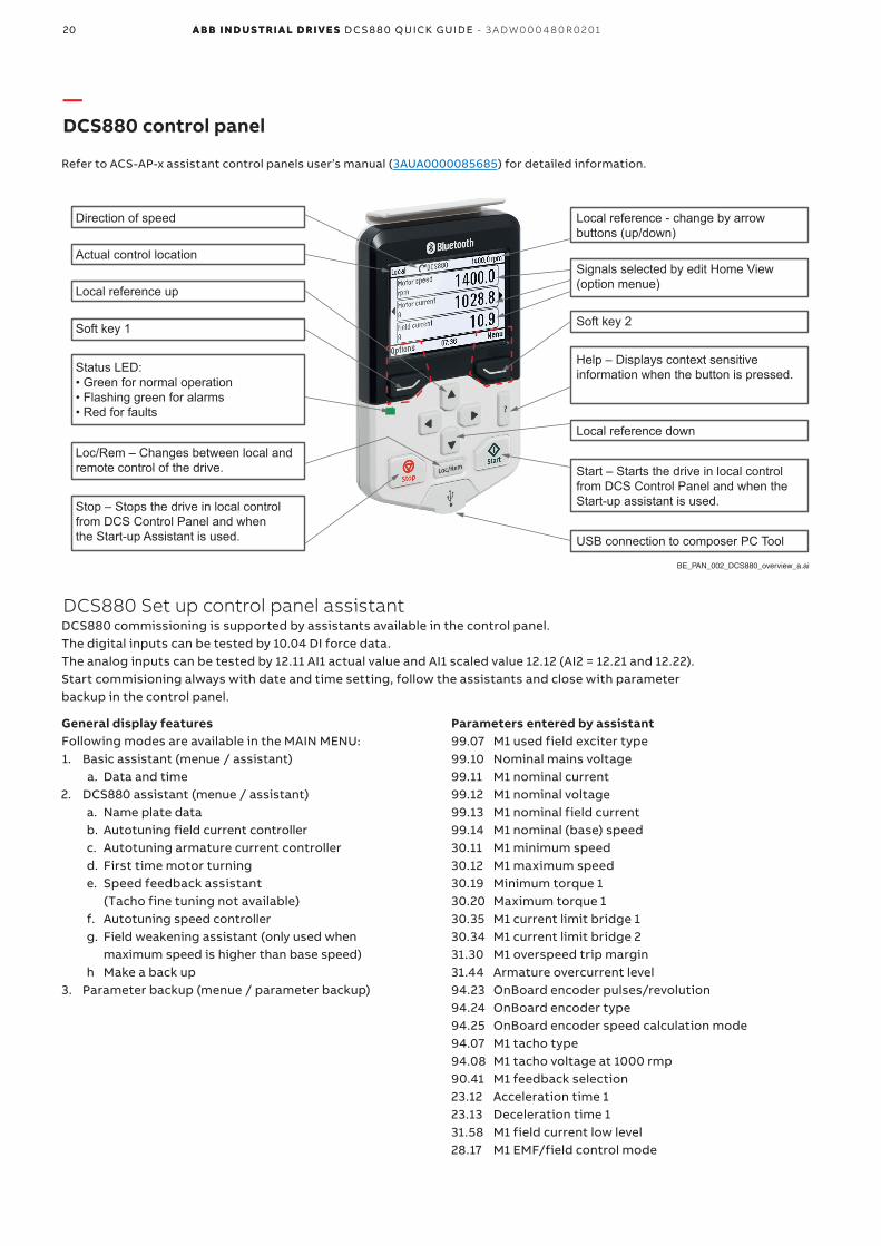
20 A B B i n d u s tr i A l d r i v e s D C S 8 8 0 Q u i Ck g u i D e - 3 A DW 0 0 0 4 8 0 R 0 2 0120 A B B i n d u s tr i A l d r i v e s D C S 8 8 0 Q u i Ck g u iD e
—DCS880 control panel
Refer to ACS-AP-x assistant control panels user’s manual (3AUA0000085685) for detailed information.
BE_PAN_002_DCS880_overview_a.ai
Status LED:• Green for normal operation• Flashing green for alarms• Red for faults
Soft key 1
Local reference up
Loc/Rem – Changes between local and remote control of the drive.
Stop – Stops the drive in local control from DCS Control Panel and when the Start-up Assistant is used.
Soft key 2
Local reference down
Help – Displays context sensitive information when the button is pressed.
Start – Starts the drive in local control from DCS Control Panel and when the Start-up assistant is used.
USB connection to composer PC Tool
Direction of speed
Actual control location
Local reference - change by arrow buttons (up/down)
Signals selected by edit Home View(option menue)
DCS880 Set up control panel assistant
General display featuresFollowing modes are available in the MAIN MENU:1. Basic assistant (menue / assistant)
a. Data and time2. DCS880 assistant (menue / assistant)
a. Name plate datab. Autotuning field current controllerc. Autotuning armature current controllerd. First time motor turninge. Speed feedback assistant
(Tacho fine tuning not available)f. Autotuning speed controllerg. Field weakening assistant (only used when
maximum speed is higher than base speed)h Make a back up
3. Parameter backup (menue / parameter backup)
Parameters entered by assistant99.07 M1 used field exciter type99.10 Nominal mains voltage99.11 M1 nominal current 99.12 M1 nominal voltage99.13 M1 nominal field current99.14 M1 nominal (base) speed30.11 M1 minimum speed30.12 M1 maximum speed30.19 Minimum torque 130.20 Maximum torque 130.35 M1 current limit bridge 130.34 M1 current limit bridge 231.30 M1 overspeed trip margin31.44 Armature overcurrent level94.23 OnBoard encoder pulses/revolution94.24 OnBoard encoder type94.25 OnBoard encoder speed calculation mode94.07 M1 tacho type94.08 M1 tacho voltage at 1000 rmp90.41 M1 feedback selection23.12 Acceleration time 123.13 Deceleration time 131.58 M1 field current low level28.17 M1 EMF/field control mode
DCS880 commissioning is supported by assistants available in the control panel. The digital inputs can be tested by 10.04 DI force data. The analog inputs can be tested by 12.11 AI1 actual value and AI1 scaled value 12.12 (AI2 = 12.21 and 12.22).Start commisioning always with date and time setting, follow the assistants and close with parameter backup in the control panel.
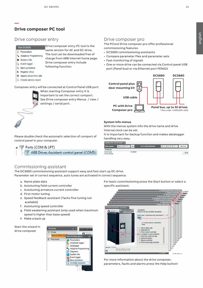
21D C D r i v e s 21D C D r i v e s
eng
lish
—Drive composer PC tool
Drive composer entry Drive composer entry PC tool is the same version for AC and DC drive. The tool can be downloaded free of charge from ABB internet home page.Drive composer entry include following function:
Composer entry will be connected at Control Panel USB port:When starting Composer entry it is important to set the correct comport.See Drive composer entry Menue / view / settings / serial port.
Please double check the automatic selection of comport of control panel in your computer.
Drive composer proThe PCtool Drive composer pro offer professional commissioning features:• DCS880 commissioning assistants• Compare parameter files and parameter sets• Fast monitoring of signals• One or more drive can be connected via Control panel USB
port (Panel bus) or via Ethernet port FENA21
Control panel plus door mounting kit
PC with Drive Composer pro
USB cable
Panel bus, up to 32 drives
*
DCS880 DCS880
* Plus code: +J428 (DPI-H01)
*
System info menueWith the menue system info the drive name and drive internal clock can be set.It is important for backup function and makes datalogger handling very easy.
For basic commissioning press the Start button or select a specific assistant:
CT_002_wizard_a.ai
7. Speed controller8. Field weakening controller
6. Speed feedback5. First time motor tuning
4. Armature current controller3. Field current controller
2. Standard I/O1. Name plate data Next >
Next > Next >
Next > Next >
Next > Next >
Select specific assistant & press Next
For more information about the drive composer, parameters, faults and alarms press the Help button!
a. Name plate datab. Autotuning field current controllerc. Autotuning armature current controllerd. First motor tuninge. Speed feedback assistant (Tacho fine tuning not available)f. Autotuning speed controllerg. Field weakening assistant (only used when maximum speed is higher than base speed)h Make a back up
Start the wizard in drive composer
Commissioning assistantThe DCS880 commissioning assistant support easy and fast start up DC drive.Parameter set in correct sequence, auto tunes are activated in correct sequence.
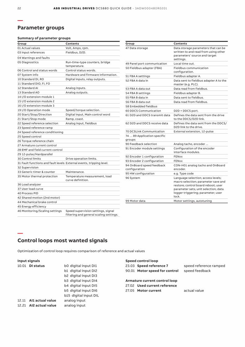
22 A B B i n d u s tr i A l d r i v e s D C S 8 8 0 Q u i Ck g u i D e - 3 A DW 0 0 0 4 8 0 R 0 2 0122 A B B i n d u s tr i A l d r i v e s D C S 8 8 0 Q u i Ck g u iD e
—Parameter groups
Summary of parameter groupsGroup Contents01 Actual values Volt, Amps, rpm.03 Input references Fieldbus, D2D.
04 Warnings and faults05 Diagnostics Run-time-type counters, bridge
temperature.06 Control and status words Control status words.07 System info Hardware and firmware information.10 Standard DI, RO Digital inputs, relay outputs.11 Standard DIO, FI, FO12 Standard AI Analog inputs.13 Standard AO Analog outputs.14 I/O extension module 115 I/O extension module 216 I/O extension module 319 I/O Operation mode Speed/torque selection.20 Start/Stop/Direction Digital input, Main control word21 Start/Stop mode Ramp, coast.22 Speed reference selection Analog input, fieldbus23 Speed reference ramp24 Speed reference conditioning25 Speed control26 Torque reference chain27 Armature current control28 EMF and field current control29 12-pulse/Hardparallel30 Control limits Drive operation limits.31 Fault functions and fault levels External events, tripping level.32 Supervision33 Generic timer & counter Maintenance.35 Motor thermal protection Temperature measurement, load
curve definition.36 Load analyzer37 User load curve40 Process PID42 Shared motion (2nd motor)44 Mechanical brake control45 Energy efficiency46 Monitoring/Scaling settings Speed supervision settings, signal
filtering and general scaling settings.
Group Contents47 Data storage Data storage parameters that can be
written to and read from using other parameters’ source and target settings.
49 Panel port communication Local time out.50 Fieldbus adapter (FBA) Fieldbus communication
configuration.51 FBA A settings Fieldbus adapter A.52 FBA A data in Data sent to fieldbus adapter A to the
master (e.g. PLC).53 FBA A data out Data read from fieldbus.54 FBA B settings Fieldbus adapter B.55 FBA B data in Data sent to fieldbus.56 FBA B data out Data read from fieldbus.58 Embedded fieldbus60 DDCS Communication D2D + DDCS port.61 D2D and DDCS transmit data Defines the data sent from the drive
to the DDCS/D2D link.62 D2D and DDCS receive data Defines the data sent from the DDCS/
D2D link to the drive.70 DCSLink Communication External extension, 12-pulse74 … 89 Application specific groups90 Feedback selection Analog tacho, encoder ...91 Encoder module settings Configuration of the encoder
interface modules.92 Encoder 1 configuration FENxx93 Encoder 2 configuration FENxx94 OnBoard speed feedback configuration
CON-H01 analog tacho and OnBoard encoder.
95 HW configuration e.g. Type code96 System Language selection; access levels;
macro selection; parameter save and restore; control board reboot; user parameter sets; unit selection; data logger triggering; parameter; user lock.
99 Motor data Motor settings, autotuning
Input signals10.01 DI status b0 digital input DI1 b1 digital input DI2 b2 digital input DI3 b3 digital input DI4 b4 digital input DI5 b5 digital input DI6 b15 digital input DIL 12.11 AI1 actual value analog input 12.21 AI2 actual value analog input
Speed control loop23.03 Speed reference 7 speed reference ramped90.01 Motor speed for control speed feedback
Armature current control loop27.02 Used current reference 27.05 Motor current actual value
—Control loops most wanted signals
Optimization of control loop requires comparison of reference and actual values
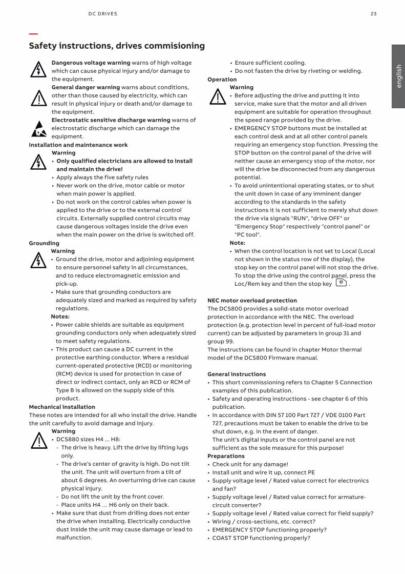
Dangerous voltage warning warns of high voltage which can cause physical injury and/or damage to the equipment.General danger warning warns about conditions, other than those caused by electricity, which can result in physical injury or death and/or damage to the equipment.Electrostatic sensitive discharge warning warns of electrostatic discharge which can damage the equipment.
Installation and maintenance work Warning• Only qualified electricians are allowed to install
and maintain the drive!• Apply always the five safety rules • Never work on the drive, motor cable or motor
when main power is applied. • Do not work on the control cables when power is
applied to the drive or to the external control circuits. Externally supplied control circuits may cause dangerous voltages inside the drive even when the main power on the drive is switched off.
GroundingWarning • Ground the drive, motor and adjoining equipment
to ensure personnel safety in all circumstances, and to reduce electromagnetic emission and pick-up.
• Make sure that grounding conductors are adequately sized and marked as required by safety regulations.
Notes: • Power cable shields are suitable as equipment
grounding conductors only when adequately sized to meet safety regulations.
• This product can cause a DC current in the protective earthing conductor. Where a residual current-operated protective (RCD) or monitoring (RCM) device is used for protection in case of direct or indirect contact, only an RCD or RCM of Type B is allowed on the supply side of this product.
Mechanical installationThese notes are intended for all who install the drive. Handle the unit carefully to avoid damage and injury.
Warning• DCS880 sizes H4 ... H8:
- The drive is heavy. Lift the drive by lifting lugs only.
- The drive’s center of gravity is high. Do not tilt the unit. The unit will overturn from a tilt of about 6 degrees. An overturning drive can cause physical injury.
- Do not lift the unit by the front cover. - Place units H4 … H6 only on their back.
• Make sure that dust from drilling does not enter the drive when installing. Electrically conductive dust inside the unit may cause damage or lead to malfunction.
—Safety instructions, drives commisioning
• Ensure sufficient cooling.• Do not fasten the drive by riveting or welding.
OperationWarning• Before adjusting the drive and putting it into
service, make sure that the motor and all driven equipment are suitable for operation throughout the speed range provided by the drive.
• EMERGENCY STOP buttons must be installed at each control desk and at all other control panels requiring an emergency stop function. Pressing the STOP button on the control panel of the drive will neither cause an emergency stop of the motor, nor will the drive be disconnected from any dangerous potential.
• To avoid unintentional operating states, or to shut the unit down in case of any imminent danger according to the standards in the safety instructions it is not sufficient to merely shut down the drive via signals "RUN", "drive OFF" or "Emergency Stop" respectively "control panel" or "PC tool".
Note: • When the control location is not set to Local (Local
not shown in the status row of the display), the stop key on the control panel will not stop the drive. To stop the drive using the control panel, press the Loc/Rem key and then the stop key .
NEC motor overload protectionThe DCS800 provides a solid-state motor overload protection in accordance with the NEC. The overload protection (e.g. protection level in percent of full-load motor current) can be adjusted by parameters in group 31 and group 99.The instructions can be found in chapter Motor thermal model of the DCS800 Firmware manual.
General instructions• This short commissioning refers to Chapter 5 Connection
examples of this publication.• Safety and operating instructions - see chapter 6 of this
publication.• In accordance with DIN 57 100 Part 727 / VDE 0100 Part
727, precautions must be taken to enable the drive to be shut down, e.g. in the event of danger. The unit’s digital inputs or the control panel are not sufficient as the sole measure for this purpose!
Preparations• Check unit for any damage!• Install unit and wire it up, connect PE• Supply voltage level / Rated value correct for electronics
and fan?• Supply voltage level / Rated value correct for armature-
circuit converter?• Supply voltage level / Rated value correct for field supply?• Wiring / cross-sections, etc. correct?• EMERGENCY STOP functioning properly?• COAST STOP functioning properly?
23D C D r i v e s 23D C D r i v e s
eng
lish
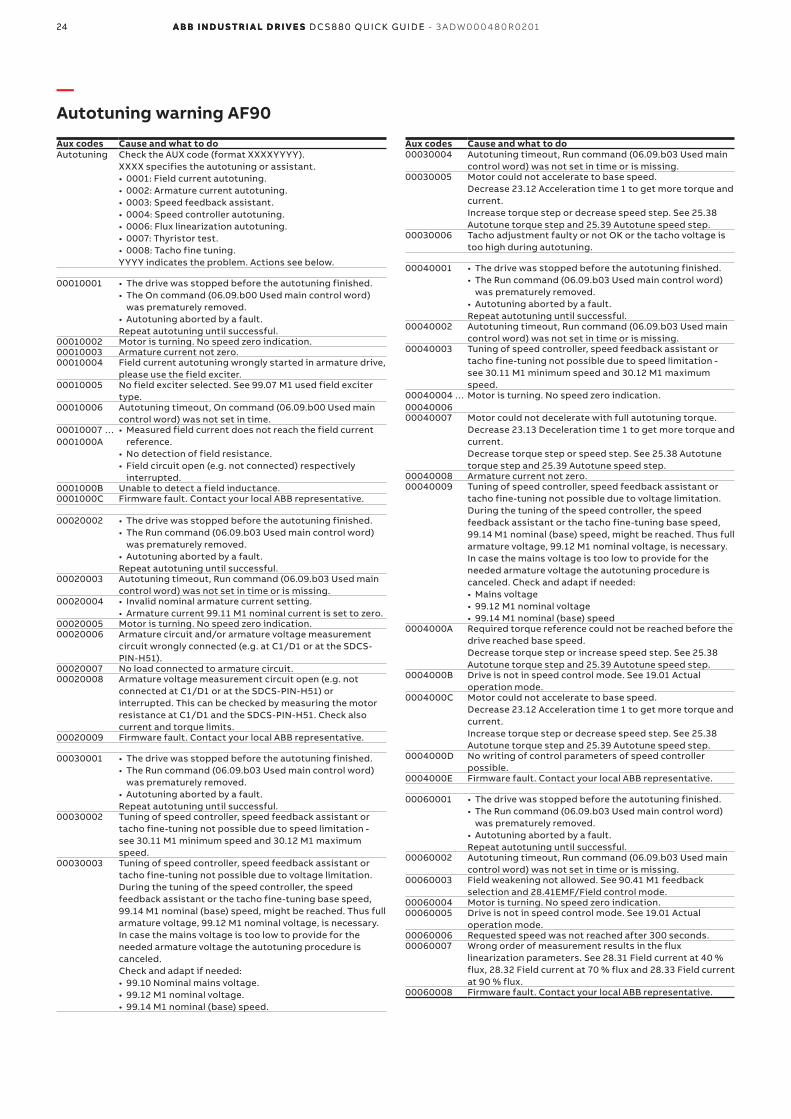
—Autotuning warning AF90
24 A B B i n d u s tr i A l d r i v e s D C S 8 8 0 Q u i Ck g u i D e - 3 A DW 0 0 0 4 8 0 R 0 2 0124 A B B i n d u s tr i A l d r i v e s D C S 8 8 0 Q u i Ck g u iD e
Aux codes Cause and what to doAutotuning Check the AUX code (format XXXXYYYY).
XXXX specifies the autotuning or assistant.• 0001: Field current autotuning.• 0002: Armature current autotuning.• 0003: Speed feedback assistant.• 0004: Speed controller autotuning.• 0006: Flux linearization autotuning.• 0007: Thyristor test.• 0008: Tacho fine tuning.YYYY indicates the problem. Actions see below.
00010001 • The drive was stopped before the autotuning finished.• The On command (06.09.b00 Used main control word)
was prematurely removed.• Autotuning aborted by a fault.Repeat autotuning until successful.
00010002 Motor is turning. No speed zero indication.00010003 Armature current not zero.00010004 Field current autotuning wrongly started in armature drive,
please use the field exciter.00010005 No field exciter selected. See 99.07 M1 used field exciter
type.00010006 Autotuning timeout, On command (06.09.b00 Used main
control word) was not set in time.00010007 … 0001000A
• Measured field current does not reach the field current reference.
• No detection of field resistance.• Field circuit open (e.g. not connected) respectively
interrupted.0001000B Unable to detect a field inductance.0001000C Firmware fault. Contact your local ABB representative.
00020002 • The drive was stopped before the autotuning finished.• The Run command (06.09.b03 Used main control word)
was prematurely removed.• Autotuning aborted by a fault.Repeat autotuning until successful.
00020003 Autotuning timeout, Run command (06.09.b03 Used main control word) was not set in time or is missing.
00020004 • Invalid nominal armature current setting.• Armature current 99.11 M1 nominal current is set to zero.
00020005 Motor is turning. No speed zero indication.00020006 Armature circuit and/or armature voltage measurement
circuit wrongly connected (e.g. at C1/D1 or at the SDCS-PIN-H51).
00020007 No load connected to armature circuit.00020008 Armature voltage measurement circuit open (e.g. not
connected at C1/D1 or at the SDCS-PIN-H51) or interrupted. This can be checked by measuring the motor resistance at C1/D1 and the SDCS-PIN-H51. Check also current and torque limits.
00020009 Firmware fault. Contact your local ABB representative.
00030001 • The drive was stopped before the autotuning finished.• The Run command (06.09.b03 Used main control word)
was prematurely removed.• Autotuning aborted by a fault.Repeat autotuning until successful.
00030002 Tuning of speed controller, speed feedback assistant or tacho fine-tuning not possible due to speed limitation - see 30.11 M1 minimum speed and 30.12 M1 maximum speed.
00030003 Tuning of speed controller, speed feedback assistant or tacho fine-tuning not possible due to voltage limitation.During the tuning of the speed controller, the speed feedback assistant or the tacho fine-tuning base speed, 99.14 M1 nominal (base) speed, might be reached. Thus full armature voltage, 99.12 M1 nominal voltage, is necessary. In case the mains voltage is too low to provide for the needed armature voltage the autotuning procedure is canceled.Check and adapt if needed:• 99.10 Nominal mains voltage.• 99.12 M1 nominal voltage.• 99.14 M1 nominal (base) speed.
Aux codes Cause and what to do00030004 Autotuning timeout, Run command (06.09.b03 Used main
control word) was not set in time or is missing.00030005 Motor could not accelerate to base speed.
Decrease 23.12 Acceleration time 1 to get more torque and current.Increase torque step or decrease speed step. See 25.38 Autotune torque step and 25.39 Autotune speed step.
00030006 Tacho adjustment faulty or not OK or the tacho voltage is too high during autotuning.
00040001 • The drive was stopped before the autotuning finished.• The Run command (06.09.b03 Used main control word)
was prematurely removed.• Autotuning aborted by a fault.Repeat autotuning until successful.
00040002 Autotuning timeout, Run command (06.09.b03 Used main control word) was not set in time or is missing.
00040003 Tuning of speed controller, speed feedback assistant or tacho fine-tuning not possible due to speed limitation - see 30.11 M1 minimum speed and 30.12 M1 maximum speed.
00040004 … 00040006
Motor is turning. No speed zero indication.
00040007 Motor could not decelerate with full autotuning torque.Decrease 23.13 Deceleration time 1 to get more torque and current.Decrease torque step or speed step. See 25.38 Autotune torque step and 25.39 Autotune speed step.
00040008 Armature current not zero.00040009 Tuning of speed controller, speed feedback assistant or
tacho fine-tuning not possible due to voltage limitation.During the tuning of the speed controller, the speed feedback assistant or the tacho fine-tuning base speed, 99.14 M1 nominal (base) speed, might be reached. Thus full armature voltage, 99.12 M1 nominal voltage, is necessary. In case the mains voltage is too low to provide for the needed armature voltage the autotuning procedure is canceled. Check and adapt if needed:• Mains voltage• 99.12 M1 nominal voltage• 99.14 M1 nominal (base) speed
0004000A Required torque reference could not be reached before the drive reached base speed.Decrease torque step or increase speed step. See 25.38 Autotune torque step and 25.39 Autotune speed step.
0004000B Drive is not in speed control mode. See 19.01 Actual operation mode.
0004000C Motor could not accelerate to base speed.Decrease 23.12 Acceleration time 1 to get more torque and current.Increase torque step or decrease speed step. See 25.38 Autotune torque step and 25.39 Autotune speed step.
0004000D No writing of control parameters of speed controller possible.
0004000E Firmware fault. Contact your local ABB representative.
00060001 • The drive was stopped before the autotuning finished.• The Run command (06.09.b03 Used main control word)
was prematurely removed.• Autotuning aborted by a fault.Repeat autotuning until successful.
00060002 Autotuning timeout, Run command (06.09.b03 Used main control word) was not set in time or is missing.
00060003 Field weakening not allowed. See 90.41 M1 feedback selection and 28.41EMF/Field control mode.
00060004 Motor is turning. No speed zero indication.00060005 Drive is not in speed control mode. See 19.01 Actual
operation mode.00060006 Requested speed was not reached after 300 seconds.00060007 Wrong order of measurement results in the flux
linearization parameters. See 28.31 Field current at 40 % flux, 28.32 Field current at 70 % flux and 28.33 Field current at 90 % flux.
00060008 Firmware fault. Contact your local ABB representative.

25D C D r i v e s 25D C D r i v e s
Ap
pen
dix
—Environmental conditions
System connections Environmental limit valuesVoltage, 3-phase: 100 ... ≤ 1000 V acc. to IEC 60038 Permissible cooling air temp.Voltage deviation: ±10 % continuous;
±15 % short-time *- at converter module air inlet: 0 ... +55°C
Rated frequency: 50 Hz or 60 Hz with rated DC current: 0 ... +40°CStatic frequency deviation: 50 Hz ± 2 %; 60 Hz ± 2 % with different DC current: +30 ... +55°CDynamic: frequency range: 50 Hz ± 5 Hz; 60 Hz ± 5 Hz - Options: 0 ... +40°Cdf/dt: 17 % / s Relative humidity (at 5...+40°C): 5 ... 95 %, no condensation* = 0.5 ... 30 cycles Relative humidity (at 0...+5°C): 5 ... 50 %, no condensationPlease note: Special consideration must be taken for voltage deviation in regenerative mode.
Change of the ambient temp.: < 0.5°C / minute
Storage temperature: -40 ... +55°CDegree of protection Transport temperature: -40 ... +70°CConverter module and options (line chokes, fuse holder, field exciter, etc.):
IEC: IP 00; UL: open type Pollution degree (IEC 60664-1, IEC 60439-1).
2
Overvoltage category(IEC 60664-1) (all inputs): III
Protective class Site elevation(IEC 61800-5-1): I < 1000 m above M.S.L.: 100 %, without current reduction
> 1000 m above M.S.L.: with current reduction, Paint finishConverter module: Body RAL 7012; Permissible supply systems: IT, TN, TT (neutral earthed),
Cover RAL 9017 & RAL 9002 IT (corner earthed),TT (corner earthed)
Enclosed converter: Light grey RAL 7035
Sound pressure level and vibrationSize Sound pressure level LP
(1 m distance)Vibration
as module enclosed conv. as moduleH1 55 dBA 68 dBA
3 mm, 2 … 9 Hz1 g, 9 ... 200 Hz
H2 55 dBA 72 dBAH3 60 dBA 78 dBAH4 66 dBA 77 dBAH5 66 dBA -
North American StandardsIn North America the system components fulfil the requirements of the table belowRated supply
Standards
voltage Converter module Enclosed converterto 990 V UL 61800-5-1
Power Conversion EquipmentCSA C 22.2 No. 274-13Industrial Control Equipment, Industrial ProductsAvailable for converter modules including field exciter units. Types with UL mark:• see UL Listing www.ul.com /
certificate no. E196914 • or on request
UL/CSA types: on request
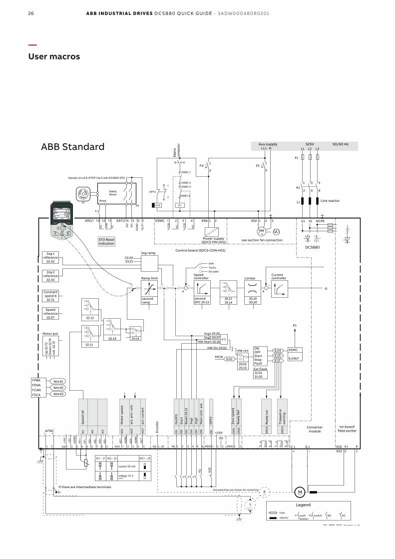
26 A B B i n d u s tr i A l d r i v e s D C S 8 8 0 Q u i Ck g u i D e - 3 A DW 0 0 0 4 8 0 R 0 2 0126 A B B i n d u s tr i A l d r i v e s D C S 8 8 0 Q u i Ck g u iD e
—User macros
ONOFFStartStopFault
Ext Fault31.01 31.02
X99: 1 2 X52: 1 2 3 U1 W1V1 PE
L1 L2 L3
F1
M~
F51
2
C 1 D 1
AITAC
AI1
AI2
AI3
AO
1
AO
2
IAC
T
_ +
T
E
0V
1 2 1...10X5:
+
_
F41
2
1 3 5
2 4 6
L1
X10:X10: F+ F-
2 1
L1.1 N
SF_880_037_macro_c.ai
DCS880(SDCS-PIN-H01)
M
+ _
DI1
DI2
DI3
DI4
DI5
DI6
DIL
+24V DIO
1
DIO
2
X6: 1 2 3 4 5 6 XD24 1 2 3 XDIO 1 2
30.1930.20
Limiter
secondSPC 25.13
Speed controller
Currentcontroller
-
EMFTacho
Encoder
Ramp limit
Jog ramp23.2023.21
secondramp
22.11
20.14
Up
22.
73D
own
22.7
4In
it 2
2.72
Motor pot
FPBAFENAFCANFSCA
Word1
Word2
Word3
Jog1 20.26Jog2 20.27
HW Start 10.16≥ 1
6.01
HW On 20.02HW ctrl
20.0120.15
Jog 1reference
22.42
Jog 2reference
22.43
Constantspeed 6
22.31
Speedreference
22.07 22.12
22.14
+
19.1219.14
-+
6.15
6.24
6.17
Enco
der
MCW
CO
M
NO
CO
M
NO
XSMC 3 421
+10V
-10V
AG
ND
AI1
-
AI2
+
AI2
-
AI1
+
AO
2
AG
ND
AG
ND
AO
1
AI3
-
AI3
+
XAI 1 2 3 4 5 6 7 XAO 1 2 3 4
IAC
T
58 9
NC
CO
M
NO
NC
CO
M
NO
NC
CO
M
NO
1211 2221 2313
XR
O2
3231 33
XR
O3
AI1 - J1 AI2 - J2 AO1 - J5
current 20 mA
voltage 10 V default
OU
T1
SG
ND
IN1
IN2
NC
CO
M
NO
4 3 2 1 XRO1 12 1113 XSTO
K1
525V 50/60 Hz
K1
K15
K15
XSMC:1
XSMC:2XSMC:3
XSMC:4
Mai
nsco
ntac
tor
1
2
OFF2
STO ResetIndication
XSMC
6.24b7
K1
Reset
SafetyRelais
Sample circuit E-STOP Cat 0 with DCS880 STO
S1A4
OnO
ff1
Star
tRe
set
20.1
3
Jog
1
Jog
2
Mai
n co
nt. a
ck.
OFF
2
Zer
o s
pee
d
Read
y Re
f
Read
y ru
n
Trip
ped
or
war
ning
Spee
d r
ef.
act.
cur
rent
act.
arm
. vo
lt.
Mo
tor
spee
d
ABB Standard
K15
K1
Control board (SDCS-CON-H01)
Power supply
Convertermodule
'on board' field exciter
see section fan connection
the polarities are shown for motoringif there are intermediate terminals
Aux.supply
Legend
fuse
reactor
Line reactor
push button
switch NO NC
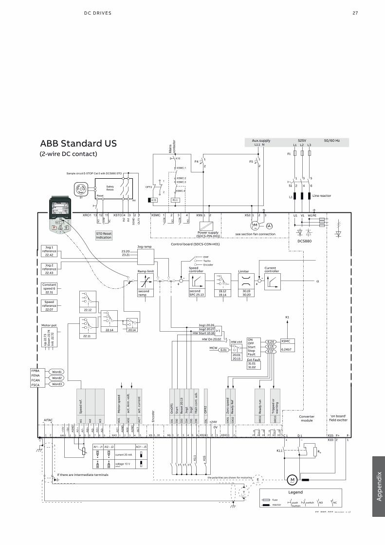
27D C D r i v e s 27D C D r i v e s
Ap
pen
dix
ONOFFStartStopFault
Ext Fault31.01 31.02
X99: 1 2 X52: 1 2 3 U1 W1V1 PE
L1 L2 L3
F1
M~
F51
2
C 1 D 1
AITAC
AI1
AI2
AI3
AO
1
AO
2
IAC
T
_ +
T
E
0V
1 2 1...10X5:
+
_
F41
2
1 3 5
2 4 6
L1
X10:X10: F+ F-
2 1
L1.1 N
SF_880_037_macro_c.ai
DCS880(SDCS-PIN-H01)
M
+ _
DI1
DI2
DI3
DI4
DI5
DI6
DIL
+24V DIO
1
DIO
2
X6: 1 2 3 4 5 6 XD24 1 2 3 XDIO 1 2
30.1930.20
Limiter
secondSPC 25.13
Speed controller
Currentcontroller
-
EMFTacho
Encoder
Ramp limit
Jog ramp23.2023.21
secondramp
22.11
20.14
Up
22.
73D
own
22.7
4In
it 2
2.72
Motor pot
FPBAFENAFCANFSCA
Word1
Word2
Word3
Jog1 20.26Jog2 20.27
HW Start 10.16≥ 1
6.01
HW On 20.02HW ctrl
20.0120.15
Jog 1reference
22.42
Jog 2reference
22.43
Constantspeed 6
22.31
Speedreference
22.07 22.12
22.14
+
19.1219.14
-+
6.15
6.24
6.17
Enco
der
MCW
CO
M
NO
CO
M
NO
XSMC 3 421
+10V
-10V
AG
ND
AI1
-
AI2
+
AI2
-
AI1
+
AO
2
AG
ND
AG
ND
AO
1
AI3
-
AI3
+
XAI 1 2 3 4 5 6 7 XAO 1 2 3 4
IAC
T
58 9
NC
CO
M
NO
NC
CO
M
NO
NC
CO
M
NO
1211 2221 2313
XR
O2
3231 33
XR
O3
AI1 - J1 AI2 - J2 AO1 - J5
current 20 mA
voltage 10 V default
OU
T1
SG
ND
IN1
IN2
NC
CO
M
NO
4 3 2 1 XRO1 12 1113 XSTO
K1
525V 50/60 Hz
K1
K15
K15
XSMC:1
XSMC:2XSMC:3
XSMC:4
Mai
nsco
ntac
tor
1
2
OFF2
STO ResetIndication
XSMC
6.24b7
K1
Reset
SafetyRelais
Sample circuit E-STOP Cat 0 with DCS880 STO
S1A4
K1.1 RB
S1
K1.1
Read
y Re
f
Spee
d r
ef.
Mo
tor
spee
d
act.
Arm
. vo
lt.
act.
cur
rent
ABB Standard US
Star
t
Rese
t 20
.13
OnO
ff1
Jog
1
Jog
2
Mai
n co
nt. a
ck.
Zer
o s
pee
d
OFF
2
Read
y ru
n
Trip
ped
or
war
ning
K15
K1.
1
(2-wire DC contact)
Control board (SDCS-CON-H01)
Power supply
Convertermodule
'on board' field exciter
see section fan connection
the polarities are shown for motoringif there are intermediate terminals
Aux.supply
Legend
fuse
reactor
Line reactor
push button
switch NO NC

28 A B B i n d u s tr i A l d r i v e s D C S 8 8 0 Q u i Ck g u i D e - 3 A DW 0 0 0 4 8 0 R 0 2 0128 A B B i n d u s tr i A l d r i v e s D C S 8 8 0 Q u i Ck g u iD e
ONOFFStartStopFault
Ext Fault31.01 31.02
X99: 1 2 X52: 1 2 3 U1 W1V1 PE
L1 L2 L3
F1
M~
F51
2
C 1 D 1
AITAC
AI1
AI2
AI3
AO
1
AO
2
IAC
T
_ +
T
E
0V
1 2 1...10X5:
+
_
F41
2
1 3 5
2 4 6
L1
X10:X10: F+ F-
2 1
L1.1 N
SF_880_037_macro_c.ai
DCS880(SDCS-PIN-H01)
M
+ _
DI1
DI2
DI3
DI4
DI5
DI6
DIL
+24V DIO
1
DIO
2
X6: 1 2 3 4 5 6 XD24 1 2 3 XDIO 1 2
30.1930.20
Limiter
secondSPC 25.13
Speed controller
Currentcontroller
-
EMFTacho
Encoder
Ramp limit
Jog ramp23.2023.21
secondramp
22.11
20.14
Up
22.
73D
own
22.7
4In
it 2
2.72
Motor pot
FPBAFENAFCANFSCA
Word1
Word2
Word3
Jog1 20.26Jog2 20.27
HW Start 10.16≥ 1
6.01
HW On 20.02HW ctrl
20.0120.15
Jog 1reference
22.42
Jog 2reference
22.43
Constantspeed 6
22.31
Speedreference
22.07 22.12
22.14
+
19.1219.14
-+
6.15
6.24
6.17
Enco
der
MCW
CO
M
NO
CO
M
NO
XSMC 3 421
+10V
-10V
AG
ND
AI1
-
AI2
+
AI2
-
AI1
+
AO
2
AG
ND
AG
ND
AO
1
AI3
-
AI3
+
XAI 1 2 3 4 5 6 7 XAO 1 2 3 4
IAC
T
58 9
NC
CO
M
NO
NC
CO
M
NO
NC
CO
M
NO
1211 2221 2313
XR
O2
3231 33
XR
O3
AI1 - J1 AI2 - J2 AO1 - J5
current 20 mA
voltage 10 V default
OU
T1
SG
ND
IN1
IN2
NC
CO
M
NO
4 3 2 1 XRO1 12 1113 XSTO
K1
525V 50/60 Hz
K1
K15
K15
XSMC:1
XSMC:2XSMC:3
XSMC:4
Mai
nsco
ntac
tor
1
2
OFF2
STO ResetIndication
XSMC
6.24b7
K1
Reset
SafetyRelais
Sample circuit E-STOP Cat 0 with DCS880 STO
S1A4
Fix
spee
d6
Mai
n co
nt. a
ck.
Rese
t 20
.13
OFF
Sto
p p
ulse
ON
Sta
rt p
ulse
Zer
o s
pee
d
Read
y re
f.
static pulse
Spee
d r
ef.
Mo
tor
spee
d
act.
Arm
. vo
lt.
act.
cur
rent
Standard 3-wire
static pulse
Off
2
Read
y ru
n
Trip
ped
or
war
ning
K15
K1
Control board (SDCS-CON-H01)
Power supply
Convertermodule
'on board' field exciter
see section fan connection
the polarities are shown for motoringif there are intermediate terminals
Aux.supply
Legend
fuse
reactor
Line reactor
push button
switch NO NC
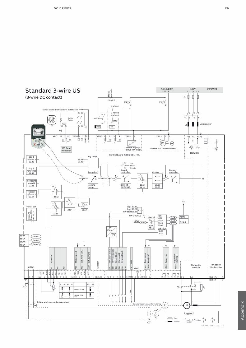
29D C D r i v e s 29D C D r i v e s
Ap
pen
dix
ONOFFStartStopFault
Ext Fault31.01 31.02
X99: 1 2 X52: 1 2 3 U1 W1V1 PE
L1 L2 L3
F1
M~
F51
2
C 1 D 1
AITAC
AI1
AI2
AI3
AO
1
AO
2
IAC
T
_ +
T
E
0V
1 2 1...10X5:
+
_
F41
2
1 3 5
2 4 6
L1
X10:X10: F+ F-
2 1
L1.1 N
SF_880_037_macro_c.ai
DCS880(SDCS-PIN-H01)
M
+ _
DI1
DI2
DI3
DI4
DI5
DI6
DIL
+24V DIO
1
DIO
2
X6: 1 2 3 4 5 6 XD24 1 2 3 XDIO 1 2
30.1930.20
Limiter
secondSPC 25.13
Speed controller
Currentcontroller
-
EMFTacho
Encoder
Ramp limit
Jog ramp23.2023.21
secondramp
22.11
20.14
Up
22.
73D
own
22.7
4In
it 2
2.72
Motor pot
FPBAFENAFCANFSCA
Word1
Word2
Word3
Jog1 20.26Jog2 20.27
HW Start 10.16≥ 1
6.01
HW On 20.02HW ctrl
20.0120.15
Jog 1reference
22.42
Jog 2reference
22.43
Constantspeed 6
22.31
Speedreference
22.07 22.12
22.14
+
19.1219.14
-+
6.15
6.24
6.17
Enco
der
MCW
CO
M
NO
CO
M
NO
XSMC 3 421
+10V
-10V
AG
ND
AI1
-
AI2
+
AI2
-
AI1
+
AO
2
AG
ND
AG
ND
AO
1
AI3
-
AI3
+
XAI 1 2 3 4 5 6 7 XAO 1 2 3 4
IAC
T
58 9
NC
CO
M
NO
NC
CO
M
NO
NC
CO
M
NO
1211 2221 2313
XR
O2
3231 33
XR
O3
AI1 - J1 AI2 - J2 AO1 - J5
current 20 mA
voltage 10 V default
OU
T1
SG
ND
IN1
IN2
NC
CO
M
NO
4 3 2 1 XRO1 12 1113 XSTO
K1
525V 50/60 Hz
K1
K15
K15
XSMC:1
XSMC:2XSMC:3
XSMC:4
Mai
nsco
ntac
tor
1
2
OFF2
STO ResetIndication
XSMC
6.24b7
K1
Reset
SafetyRelais
Sample circuit E-STOP Cat 0 with DCS880 STO
S1A4
DC
co
ntac
t6.
24b
10
Exte
rnal
faul
t
Fix
spee
d6
Rese
t 20
.13
OFF
Sto
p p
ulse
ON
Sta
rt p
ulse
Zer
o s
pee
d
Read
y re
f.
static pulse
Spee
d r
ef.
Mo
tor
spee
d
act.
Arm
. vo
lt.
act.
cur
rent
static pulse
Off
2
Read
y ru
n
Trip
ped
or
war
ning
Standard 3-wire US(3-wire DC contact)
XR
O1
K1.1 RB
S1
K15
Control board (SDCS-CON-H01)
Power supply
Convertermodule
'on board' field exciter
see section fan connection
the polarities are shown for motoringif there are intermediate terminals
Aux.supply
Legend
fuse
reactor
Line reactor
push button
switch NO NC

30 A B B i n d u s tr i A l d r i v e s D C S 8 8 0 Q u i Ck g u i D e - 3 A DW 0 0 0 4 8 0 R 0 2 0130 A B B i n d u s tr i A l d r i v e s D C S 8 8 0 Q u i Ck g u iD e
ONOFFStartStopFault
Ext Fault31.01 31.02
X99: 1 2 X52: 1 2 3 U1 W1V1 PE
L1 L2 L3
F1
M~
F51
2
C 1 D 1
AITAC
AI1
AI2
AI3
AO
1
AO
2
IAC
T
_ +
T
E
0V
1 2 1...10X5:
+
_
F41
2
1 3 5
2 4 6
L1
X10:X10: F+ F-
2 1
L1.1 N
SF_880_037_macro_c.ai
DCS880(SDCS-PIN-H01)
M
+ _
DI1
DI2
DI3
DI4
DI5
DI6
DIL
+24V DIO
1
DIO
2
X6: 1 2 3 4 5 6 XD24 1 2 3 XDIO 1 2
30.1930.20
Limiter
secondSPC 25.13
Speed controller
Currentcontroller
-
EMFTacho
Encoder
Ramp limit
Jog ramp23.2023.21
secondramp
22.11
20.14
Up
22.
73D
own
22.7
4In
it 2
2.72
Motor pot
FPBAFENAFCANFSCA
Word1
Word2
Word3
Jog1 20.26Jog2 20.27
HW Start 10.16≥ 1
6.01
HW On 20.02HW ctrl
20.0120.15
Jog 1reference
22.42
Jog 2reference
22.43
Constantspeed 6
22.31
Speedreference
22.07 22.12
22.14
+
19.1219.14
-+
6.15
6.24
6.17
Enco
der
MCW
CO
M
NO
CO
M
NO
XSMC 3 421
+10V
-10V
AG
ND
AI1
-
AI2
+
AI2
-
AI1
+
AO
2
AG
ND
AG
ND
AO
1
AI3
-
AI3
+
XAI 1 2 3 4 5 6 7 XAO 1 2 3 4
IAC
T
58 9
NC
CO
M
NO
NC
CO
M
NO
NC
CO
M
NO
1211 2221 2313
XR
O2
3231 33
XR
O3
AI1 - J1 AI2 - J2 AO1 - J5
current 20 mA
voltage 10 V default
OU
T1
SG
ND
IN1
IN2
NC
CO
M
NO
4 3 2 1 XRO1 12 1113 XSTO
K1
525V 50/60 Hz
K1
K15
K15
XSMC:1
XSMC:2XSMC:3
XSMC:4
Mai
nsco
ntac
tor
1
2
OFF2
STO ResetIndication
XSMC
6.24b7
K1
Reset
SafetyRelais
Sample circuit E-STOP Cat 0 with DCS880 STO
S1A4
Star
tSto
p
Han
d/A
uto
Rese
t 20
.13
Dir
ecti
on
OnO
ff1
Off
2
Read
y R
un
Read
y Re
f
Spee
d r
ef.
Mo
tor
spee
d
Torq
ue
act.
cur
rent
Local I/O / Fieldbus
Read
y o
n
Trip
ped
K15
Control board (SDCS-CON-H01)
Power supply
Convertermodule
'on board' field exciter
see section fan connection
the polarities are shown for motoringif there are intermediate terminals
Aux.supply
Legend
fuse
reactor
Line reactor
push button
switch NO NC

31D C D r i v e s 31D C D r i v e s
Ap
pen
dix
ONOFFStartStopFault
Ext Fault31.01 31.02
X99: 1 2 X52: 1 2 3 U1 W1V1 PE
L1 L2 L3
F1
M~
F51
2
C 1 D 1
AITAC
AI1
AI2
AI3
AO
1
AO
2
IAC
T
_ +
T
E
0V
1 2 1...10X5:
+
_
F41
2
1 3 5
2 4 6
L1
X10:X10: F+ F-
2 1
L1.1 N
SF_880_037_macro_c.ai
DCS880(SDCS-PIN-H01)
M
+ _
DI1
DI2
DI3
DI4
DI5
DI6
DIL
+24V DIO
1
DIO
2
X6: 1 2 3 4 5 6 XD24 1 2 3 XDIO 1 2
30.1930.20
Limiter
secondSPC 25.13
Speed controller
Currentcontroller
-
EMFTacho
Encoder
Ramp limit
Jog ramp23.2023.21
secondramp
22.11
20.14
Up
22.
73D
own
22.7
4In
it 2
2.72
Motor pot
FPBAFENAFCANFSCA
Word1
Word2
Word3
Jog1 20.26Jog2 20.27
HW Start 10.16≥ 1
6.01
HW On 20.02HW ctrl
20.0120.15
Jog 1reference
22.42
Jog 2reference
22.43
Constantspeed 6
22.31
Speedreference
22.07 22.12
22.14
+
19.1219.14
-+
6.15
6.24
6.17
Enco
der
MCW
CO
M
NO
CO
M
NO
XSMC 3 421
+10V
-10V
AG
ND
AI1
-
AI2
+
AI2
-
AI1
+
AO
2
AG
ND
AG
ND
AO
1
AI3
-
AI3
+
XAI 1 2 3 4 5 6 7 XAO 1 2 3 4
IAC
T
58 9
NC
CO
M
NO
NC
CO
M
NO
NC
CO
M
NO
1211 2221 2313
XR
O2
3231 33
XR
O3
AI1 - J1 AI2 - J2 AO1 - J5
current 20 mA
voltage 10 V default
OU
T1
SG
ND
IN1
IN2
NC
CO
M
NO
4 3 2 1 XRO1 12 1113 XSTO
K1
525V 50/60 Hz
K1
K15
K15
XSMC:1
XSMC:2XSMC:3
XSMC:4
Mai
nsco
ntac
tor
1
2
OFF2
STO ResetIndication
XSMC
6.24b7
K1
Reset
SafetyRelais
Sample circuit E-STOP Cat 0 with DCS880 STO
S1A4
On
+ R
un
Dir
ecti
on
Pot
dow
n
Pot
up
Rese
t 20
.13
Off
2
Read
y R
un
Read
y re
f.
Mo
tor
spee
d
Torq
ue
act.
cur
rent
Motor potentiometer
Spee
d r
ef.
K15
Read
y o
n
Trip
ped
Control board (SDCS-CON-H01)
Power supply
Convertermodule
'on board' field exciter
see section fan connection
the polarities are shown for motoringif there are intermediate terminals
Aux.supply
Legend
fuse
reactor
Line reactor
push button
switch NO NC

32 A B B i n d u s tr i A l d r i v e s D C S 8 8 0 Q u i Ck g u i D e - 3 A DW 0 0 0 4 8 0 R 0 2 0132 A B B i n d u s tr i A l d r i v e s D C S 8 8 0 Q u i Ck g u iD e
ONOFFStartStopFault
Ext Fault31.01 31.02
X99: 1 2 X52: 1 2 3 U1 W1V1 PE
L1 L2 L3
F1
M~
F51
2
C 1 D 1
AITAC
AI1
AI2
AI3
AO
1
AO
2
IAC
T
_ +
T
E
0V
1 2 1...10X5:
+
_
F41
2
1 3 5
2 4 6
L1
X10:X10: F+ F-
2 1
L1.1 N
SF_880_037_macro_c.ai
DCS880(SDCS-PIN-H01)
M
+ _
DI1
DI2
DI3
DI4
DI5
DI6
DIL
+24V DIO
1
DIO
2
X6: 1 2 3 4 5 6 XD24 1 2 3 XDIO 1 2
30.1930.20
Limiter
secondSPC 25.13
Speed controller
Currentcontroller
-
EMFTacho
Encoder
Ramp limit
Jog ramp23.2023.21
secondramp
22.11
20.14
Up
22.
73D
own
22.7
4In
it 2
2.72
Motor pot
FPBAFENAFCANFSCA
Word1
Word2
Word3
Jog1 20.26Jog2 20.27
HW Start 10.16≥ 1
6.01
HW On 20.02HW ctrl
20.0120.15
Jog 1reference
22.42
Jog 2reference
22.43
Constantspeed 6
22.31
Speedreference
22.07 22.12
22.14
+
19.1219.14
-+
6.15
6.24
6.17
Enco
der
MCW
CO
M
NO
CO
M
NO
XSMC 3 421
+10V
-10V
AG
ND
AI1
-
AI2
+
AI2
-
AI1
+
AO
2
AG
ND
AG
ND
AO
1
AI3
-
AI3
+
XAI 1 2 3 4 5 6 7 XAO 1 2 3 4
IAC
T
58 9
NC
CO
M
NO
NC
CO
M
NO
NC
CO
M
NO
1211 2221 2313
XR
O2
3231 33
XR
O3
AI1 - J1 AI2 - J2 AO1 - J5
current 20 mA
voltage 10 V default
OU
T1
SG
ND
IN1
IN2
NC
CO
M
NO
4 3 2 1 XRO1 12 1113 XSTO
K1
525V 50/60 Hz
K1
K15
K15
XSMC:1
XSMC:2XSMC:3
XSMC:4
Mai
nsco
ntac
tor
1
2
OFF2
STO ResetIndication
XSMC
6.24b7
K1
Reset
SafetyRelais
Sample circuit E-STOP Cat 0 with DCS880 STO
S1A4
Off
2
Star
t
Rese
t 20
.13
Spee
d/T
orq
ue
Exte
rnal
faul
t
OnO
ff1
Read
yRef
Zer
o s
pee
d
Mo
tor
Torq
ue
act.
cur
rent
Mo
tor
spee
d
Torq
ue r
ef.
Speed / Torque
Read
y o
n
DC
bre
aker
trip
pul
se
K15
Control board (SDCS-CON-H01)
Power supply
Convertermodule
'on board' field exciter
see section fan connection
the polarities are shown for motoringif there are intermediate terminals
Aux.supply
Legend
fuse
reactor
Line reactor
push button
switch NO NC
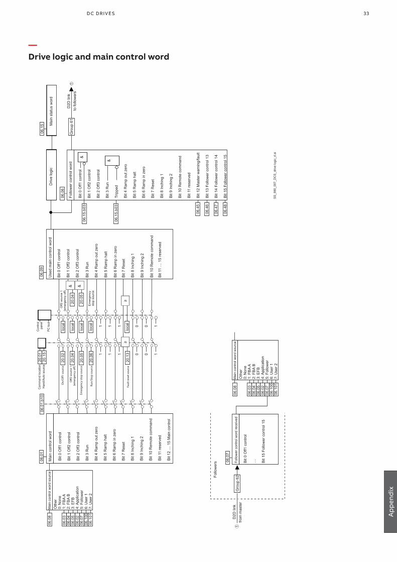
33D C D r i v e s 33D C D r i v e s
Ap
pen
dix
—Drive logic and main control word
Con
trol
pane
l
On/
Off1
sou
rce
Han
d/A
uto
sour
ceC
omm
and
loca
tion
Off2
sou
rce
1(e
mer
genc
y off
)
Off2
sou
rce
1(e
mer
genc
y of
f)
Emer
genc
y st
op s
ourc
e
Run/
Stop
sou
rce
&
Use
d m
ain
cont
rol w
ord
Mai
n co
ntro
l wor
d
Bit
0 O
ff1 c
ontro
l
Bit
1 O
ff2 c
ontro
l
Bit
2 O
ff3 c
ontro
l
Bit
3 R
un
Bit
4 R
amp
out z
ero
Bit
5 R
amp
halt
Bit
6 R
amp
in z
ero
Bit
7 R
eset
Bit
8 In
chin
g 1
Bit
9 In
chin
g 2
Bit
10 R
emot
e co
mm
and
Bit
11 re
serv
ed
Bit
12 …
15
Mai
n co
ntro
l
Driv
e lo
gic
&
Faul
t res
et s
ourc
e≥
≥
PC
tool
1 1 1 0 0 1
1 1 1 0 0 1
Mai
n co
ntro
l wor
d so
urce
Oth
er0:
Non
e1:
FB
A A
2: F
BA
B
3: E
FB
4: A
pplic
atio
n 5:
Fol
low
er
6: U
ser 1
7:
Use
r 2
06.0
8
06.0
706
.100
06.0
3
06.4
5
06.0
506
.02
06.1
01
06.0
106
.01.
b10
20.0
120
.15
20.0
2
20.0
4
20.0
5
20.0
6
20.1
3
loca
l
loca
l
loca
l
loca
l
loca
l
20.0
4
Em
erge
ncy
stop
sou
rce
20.0
5
Bit
0 O
ff1 c
ontro
l
Bit
1 O
ff2 c
ontro
l
Bit
2 O
ff3 c
ontro
l
Bit
3 R
un
Bit
4 R
amp
out z
ero
Bit
5 R
amp
halt
Bit
6 R
amp
in z
ero
Bit
7 R
eset
Bit
8 In
chin
g 1
Bit
9 In
chin
g 2
Bit
10 R
emot
e co
mm
and
Bit
11 …
15
rese
rved
06.0
9
Follo
wer
con
trol w
ord
06.0
6
Bit
0 O
ff1 c
ontro
l
Bit
1 O
ff2 c
ontro
l
Bit
2 O
ff3 c
ontro
l
Bit
3 R
un
Trip
ped
Bit
4 R
amp
out z
ero
Bit
5 R
amp
halt
Bit
6 R
amp
in z
ero
Bit
7 R
eset
Bit
8 In
chin
g 1
Bit
9 In
chin
g 2
Bit
10 R
emot
e co
mm
and
Bit
11 re
serv
ed
Bit
12 M
aste
r war
ning
/faul
t
Bit
13 F
ollo
wer
con
trol 1
3
Bit
14 F
ollo
wer
con
trol 1
4
Bit
15 F
ollo
wer
con
trol 1
5
06.0
4
Mai
n co
ntro
l wor
d so
urce
Oth
er0:
Non
e1:
FB
A A
2: F
BA
B
3: E
FB
4: A
pplic
atio
n 5:
Fol
low
er
6: U
ser 1
7:
Use
r 2
06.0
8
06.0
706
.100
06.0
3
06.0
506
.02
06.1
01
06.0
4
06.4
6
06.4
7
06.4
8
D2D
link
to fo
llow
ers
Follo
wer
con
trol w
ord
rece
ived
06.0
7
Bit
0 O
ff1 c
ontro
l
… Bit
15 F
ollo
wer
con
trol 1
5
Follo
wer
s
&
&
06.1
5.b0
3
06.1
5.b0
3
Mai
n st
atus
wor
d
06.1
5
Gro
up 6
1
D2D
link
from
mas
ter
①
SS
_880
_007
_DC
S_d
rive
logi
c_d.
ai
1
Gro
up 6
2

34 A B B i n d u s tr i A l d r i v e s D C S 8 8 0 Q u i Ck g u i D e - 3 A DW 0 0 0 4 8 0 R 0 2 0134 A B B i n d u s tr i A l d r i v e s D C S 8 8 0 Q u i Ck g u iD e
—Fieldbus control
SS
_880
_007
_DC
S_d
rive
logi
c_d.
ai
PLC
1: C
W 1
6bit
FBA
data
out
1 1:
FB
A A
Pro
file
spec
ific
func
tions
E.g
. OD
VA N
etC
tr an
d N
et R
ef
Pro
file
spec
ific
func
tions
E.g
. OD
VA N
etC
tr an
d N
et R
ef
CW
RE
F
Out
3
Out
4
Out
5
... Out
12
F-ty
pead
apte
r
For a
ny tr
ansp
aren
t16
bit
(T16
) Pro
file
Opt
ion
Fied
lbus
Par
amet
erS
ettin
gFE
NA
-xx
Pro
finet
51.0
2P
NIO
T16
Eth
erne
t IP
51.0
2E
IP T
16M
odbu
s TC
P51
.02
MB
/TC
P T1
6M
odbu
s U
DP
51.0
2M
B/U
DP
T16
FPB
A-0
1P
rofib
us51
.05
Tran
s16
FCA
N-0
1C
AN
open
51.0
5Tr
ans1
6
Sta
tus
and
Con
trol W
ord
for F
ield
bus
cont
rol
See
pag
e D
rive
logi
cin
Firm
war
e m
anua
lM
ain
cont
rol w
ord
Mai
n co
ntro
l w
ord
sour
ce
Bit0
Off1
con
trol
Bit1
Off2
con
trol
Bit2
Off3
con
trol
Bit3
Run
Bit4
Ram
p ou
t zer
oB
it5 R
amp
halt
Bit6
Ram
p in
zer
oB
it7 R
eset
Bit8
Inch
ing
1B
it9 In
chin
g 2
Bit1
0 R
emot
e co
mm
and
Bit1
1 re
serv
edB
it12
… 1
5 M
ain
cont
rol
06.0
1
4: A
pplic
atio
n3:
EFB
2: F
BA
B
0: N
one
1: F
BA
A
53.0
1
1: S
W 1
6bit
FBA
data
in1
F-ty
pead
apte
r
52.0
1
Oth
er ..
. =06
.88
[16]
FBA
SW
tra
nspa
rent
sou
rce
50.0
9
FBA
A pr
ofile
stat
us w
ord
06.8
8
06.0
8
FBA
A tra
nspa
rent
co
ntro
l wor
d
06.0
3
FBA
A ge
neric
cont
rol w
ord
06.8
6
FBA
A pr
ofile
Pro
file
to A
BB
Driv
esP
rofil
e co
nver
satio
n
50.2
9
0: A
BB
Driv
e pr
ofile
0: A
BB
Driv
e pr
ofile
1: O
DVA
bas
ic2:
OD
VA e
xten
ded
SW
AC
T
In3
In4
In5
... In12
FBA
A pr
ofile
AB
B D
rives
Pro
file
to
Pro
file
conv
ersa
tion
50.2
9
Mai
n st
atus
wor
d
06.1
5
Bit0
Rea
dy o
nB
it1 R
eady
run
Bit2
Rea
dy re
fere
nce
Bit3
Trip
ped
Bit4
Off2
sta
tus
Bit5
Off3
sta
tus
Bit6
Sw
itch-
on in
hibi
ted
Bit7
War
ning
Bit8
At s
etpo
int
Bit9
Rem
ote
Bit1
0 A
bove
leve
lB
it11
Sta
tus
cont
rol 1
1B
it12
Sta
tus
cont
rol 1
2B
it13
Sta
tus
cont
rol 1
3B
it14
Sta
tus
cont
rol 1
4B
it15
rese
rved
1: O
DVA
bas
ic2:
OD
VA e
xten
ded
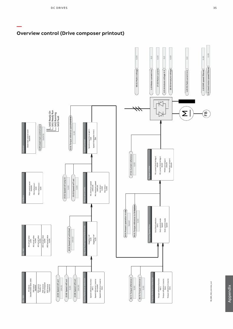
35D C D r i v e s 35D C D r i v e s
Ap
pen
dix
—Overview control (Drive composer printout)
Sp
eed
Ref
eren
ce S
elec
tio
n
Spee
d r
efer
ence
fun
ctio
nR
ef 1
Spee
d re
fere
nce
1 so
urce
AI1
scal
ed
Spee
d re
fere
nce
2 so
urce
Zer
o
Jog
and
Fix
ed S
peed
Ref
eren
ces
Jog
gin
g 1
ref
0,0
0
Jog
gin
g 2
ref
0,0
0
Ram
p a
nd L
imit
s
M1
min
imum
sp
eed
-20
00
,00
M1
max
imum
sp
eed
200
0,0
0
Acc
tim
e 1
0,5
00
Dec
tim
e 1
0,5
00
Sp
eed
Co
ntro
l
Spee
d p
rop
ort
iona
l gai
n 1
0,8
2
Spee
d in
tegr
atio
n ti
me
128
4
Torq
ue R
efer
ence
Sel
ecti
on
Torq
ue r
efer
ence
func
tio
nR
ef 1
Torq
ue r
efer
ence
1 s
our
ceZ
ero
Torq
ue r
efer
ence
2 s
our
ceZ
ero
Torq
ue/S
pee
d M
ux
Ext1
/Ext
2 se
lect
ion
EX
T1
Ext
1 co
ntro
l mo
de
Spee
d
Ext
2 co
ntro
l mo
de
Spee
d
SB_8
80_0
18_o
verv
iew
_a.a
i
Torq
ue L
imit
er
M1
curr
ent
limit
bri
dg
e 2
-50
,00
M1
curr
ent
limit
bri
dg
e 1
50,0
0
Min
imum
to
rque
1-1
00
,00
Max
imum
to
rque
110
0,0
0
DI /
DO
DI s
tatu
s0
b10
00
00
00
00
01
100
0
DIO
sta
tus
0b
00
00
RO
1 so
urce
Rea
dy
run
RO
2 so
urce
No
t en
erg
ized
RO
3 so
urce
Trip
ped
(-1)
AI /
AO
AI1
actu
al v
alue
1,0
93
AI2
actu
al v
alue
-0,0
06
AI3
actu
al v
alue
-0,0
01
AO1
actu
al v
alue
0,0
00
AO2
actu
al v
alue
0,0
00
Feld
bus M
ain
cont
rol w
ord
0x0
00
0
FB A
refe
renc
e 1
0,0
0
FB A
refe
renc
e 2
0,0
0
Co
ntro
l
Use
d m
ain
co
ntro
l wor
d0
x047
6
M FB
99.0
1 M
ain
s vo
ltag
e0
,00
1.10
Mo
tor
curr
ent
in A
0,0
27.0
5 M
oto
r cu
rren
t0
,00
1.21
Arm
atur
e vo
ltag
e in
V0,
0
28.0
5 A
rmat
ure
volt
age
0,0
0
1.29
M1
fiel
d c
urre
nt in
A0
,0
1.0
2 E
MF
spee
d f
ilter
ed0
,00
1.0
1 U
sed
mo
tor
spee
d f
ilter
ed0
,00
27.0
1 C
urre
nt
refe
ren
ce
0,0
0
19.0
1 Pr
esen
t o
per
atio
n m
ode
Sp
eed
26.0
1 To
rque
ref
eren
ce t
o li
mit
atio
n
0,0
026
.70
To
rque
refe
renc
e 1
0,0
0
26.7
1 To
rque
refe
renc
e 2
0,0
0
25.0
1 To
rque
ref
eren
ce s
peed
co
ntr
ol
0,0
0
23.0
1 Sp
eed
ref
ram
p in
0,0
0
23.0
3 S
pee
d re
f7 a
ct
0,0
0
22.0
1 Sp
eed
ref
unl
imit
ed
164
,02
22.8
1 S
peed
ref
1 ac
t
164
,01
22.8
2 S
peed
ref
2 ac
t
0,0
0
22.8
6 S
peed
ref
6 a
ct
164
,00
6.0
9 U
sed
mai
n co
ntro
l wo
rd
0x0
476
bit
0 Re
ady
On
bit
1 Re
ady
Run
bit
2 Ru
nnin
gb
it3
Faul
t
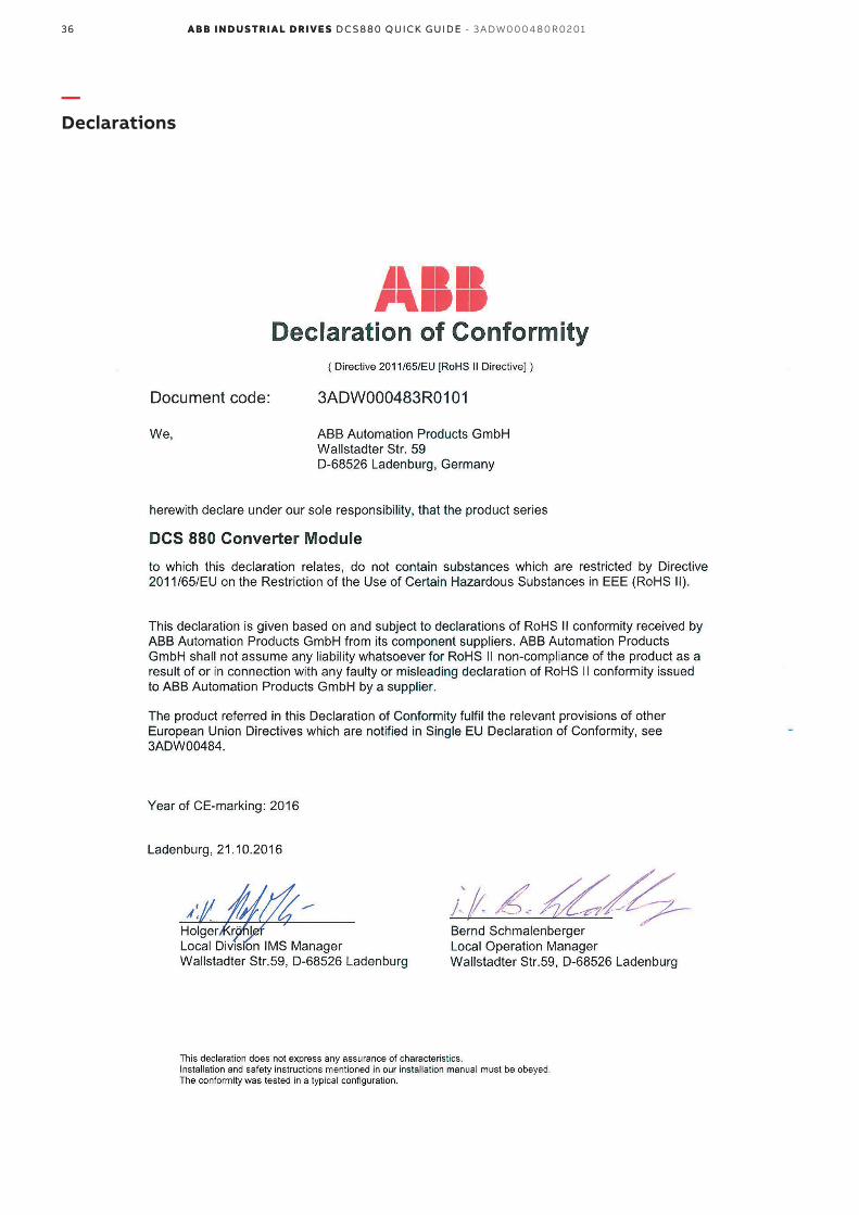
36 A B B i n d u s tr i A l d r i v e s D C S 8 8 0 Q u i Ck g u i D e - 3 A DW 0 0 0 4 8 0 R 0 2 0136 A B B i n d u s tr i A l d r i v e s D C S 8 8 0 Q u i Ck g u iD e
—Declarations

37D C D r i v e s 37D C D r i v e s
Ap
pen
dix
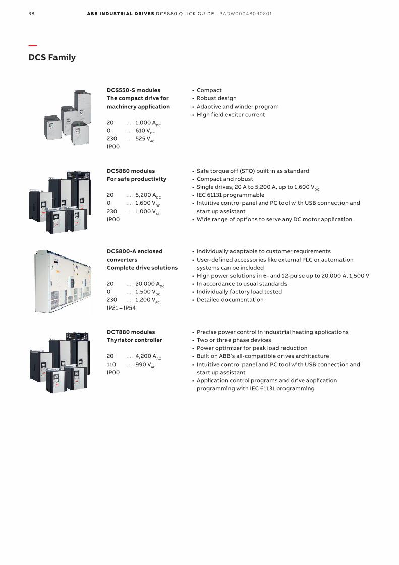
38 A B B i n d u s tr i A l d r i v e s D C S 8 8 0 Q u i Ck g u i D e - 3 A DW 0 0 0 4 8 0 R 0 2 0138 A B B i n d u s tr i A l d r i v e s D C S 8 8 0 Q u i Ck g u iD e
—DCS Family
• Compact• Robust design• Adaptive and winder program• High field exciter current
• Safe torque off (STO) built in as standard• Compact and robust• Single drives, 20 A to 5,200 A, up to 1,600 VDC
• IEC 61131 programmable• Intuitive control panel and PC tool with USB connection and
start up assistant• Wide range of options to serve any DC motor application
• Individually adaptable to customer requirements• User-defined accessories like external PLC or automation
systems can be included• High power solutions in 6- and 12-pulse up to 20,000 A, 1,500 V• In accordance to usual standards• Individually factory load tested• Detailed documentation
• Precise power control in industrial heating applications• Two or three phase devices• Power optimizer for peak load reduction• Built on ABB‘s all-compatible drives architecture• Intuitive control panel and PC tool with USB connection and
start up assistant• Application control programs and drive application
programming with IEC 61131 programming
DCS550-S modulesThe compact drive for machinery application
20 … 1,000 ADC
0 … 610 VDC
230 … 525 VAC
IP00
DCS880 modulesFor safe productivity
20 … 5,200 ADC
0 … 1,600 VDC
230 … 1,000 VAC
IP00
DCS800-A enclosed convertersComplete drive solutions
20 … 20,000 ADC
0 … 1,500 VDC
230 … 1,200 VAC
IP21 – IP54
DCT880 modulesThyristor controller
20 … 4,200 AAC
110 … 990 VAC
IP00

39D C D r i v e s 39D C D r i v e s
Ap
pen
dix

—www.abb.com/dc-driveswww.abb.com/drivespartners
© Copyright 2019 ABB. All rights reserved. Specifications subject to change without notice. 3A
DW
00
04
80
R0
201
RE
V B
EN
09
.01.
2019