d&c b292 spherical bearings - structural steel · 2019-12-03 · (c) design calculations of the...
TRANSCRIPT

Edition 1 / Revision 1 ROADS AND MARITIME SERVICES November 2019
ROADS AND MARITIME SERVICES (RMS)
RMS SPECIFICATION D&C B292
SPHERICAL BEARINGS – STRUCTURAL STEEL
NOTICE
This document is a Roads and Maritime Services D&C Specification. It has been developed for use with Design & Construct roadworks and bridgeworks contracts let by Roads and Maritime Services. It is not suitable for any other purpose and must not be used for any other purpose or in any other context.
Copyright in this document belongs to Roads and Maritime Services.
REVISION REGISTER
Ed/Rev Number
Clause Number Description of Revision Authorised
By Date
Ed 1/Rev 0 First issue. MCQ 10.08.18
Ed 1/Rev 1 Updated to accord with base (non-D&C) Specification B292 Ed 1 Rev 1.
MCQ 27.11.19


Edition 1 / Revision 1 ROADS AND MARITIME SERVICES November 2019
SPECIFICATION D&C B292
SPHERICAL BEARINGS – STRUCTURAL STEEL
Copyright – Roads and Maritime Services IC-DC-B292
VERSION FOR: DATE:


Spherical Bearings – Structural Steel D&C B292
Ed 1 / Rev 1 i
CONTENTS
CLAUSE PAGE
FOREWORD ............................................................................................................................................... II RMS Copyright and Use of this Document ................................................................................... ii Base Specification .......................................................................................................................... ii
1 GENERAL ........................................................................................................................................ 1 1.1 Scope .............................................................................................................................. 1 1.2 Structure of the Specification ......................................................................................... 1 1.3 Definitions ...................................................................................................................... 2 1.4 Quality Management System.......................................................................................... 2 1.5 Approved Bridge Components and Systems .................................................................. 3
2 DESIGN ........................................................................................................................................... 3 2.1 General ........................................................................................................................... 3 2.2 Design Calculations and Certifications .......................................................................... 4 2.3 Approved Sliding Material ............................................................................................. 4
3 MATERIALS .................................................................................................................................... 4 3.1 Mating Sliding Surfaces ................................................................................................. 4 3.2 Ferrous Materials ............................................................................................................ 5 3.3 Non-metallic Sliding Pads and Strips ............................................................................. 6 3.4 Lubricant......................................................................................................................... 6 3.5 Material Conformity ....................................................................................................... 6
4 FABRICATION ................................................................................................................................. 7 4.1 General ........................................................................................................................... 7 4.2 Flatness of Surfaces ........................................................................................................ 7 4.3 Bearing Concave and Convex Plates .............................................................................. 8 4.4 Stainless Steel Sliding Surface ....................................................................................... 8 4.5 Hard Chromium Plated Surfaces .................................................................................... 9 4.6 Guide Bars ...................................................................................................................... 9 4.7 Non-metallic Sliding Surfaces ........................................................................................ 9 4.8 Attachment Plates ......................................................................................................... 10
5 PROTECTIVE TREATMENT ............................................................................................................ 10 5.1 General ......................................................................................................................... 10 5.2 Surface Preparation ...................................................................................................... 11 5.3 Zinc Metal Spray .......................................................................................................... 11 5.4 Hot-dip Galvanizing ..................................................................................................... 11 5.5 Paint Application .......................................................................................................... 11
6 TESTING OF BEARINGS ................................................................................................................. 12 6.1 General ......................................................................................................................... 12 6.2 Geometrical Verification .............................................................................................. 12 6.3 Load Tests .................................................................................................................... 12 6.4 Criteria for Acceptance ................................................................................................. 14 6.5 Bearing Report.............................................................................................................. 14
7 IDENTIFICATION AND DELIVERY .................................................................................................. 14 7.1 Identification................................................................................................................. 14 7.2 Delivery ........................................................................................................................ 15

D&C B292 Spherical Bearings – Structural Steel
ii Ed 1 / Rev 1
ANNEXURE B292/A – JOB SPECIFIC REQUIREMENTS ............................................................................ 16
ANNEXURE B292/B – (NOT USED) ........................................................................................................ 16
ANNEXURE B292/C – SCHEDULES OF HOLD POINTS AND IDENTIFIED RECORDS ................................. 17 C1 Schedule of Hold Points .............................................................................................. 17 C2 Schedule of Identified Records .................................................................................... 17
ANNEXURE B292/D – PLANNING DOCUMENTS ..................................................................................... 17
ANNEXURE B292/E – ZP COATING SYSTEM ......................................................................................... 18
ANNEXURES B292/F TO B292/K– (NOT USED) ..................................................................................... 18
ANNEXURE B292/L – MINIMUM FREQUENCY OF TESTING ................................................................... 19
ANNEXURE B292/M – REFERENCED DOCUMENTS................................................................................ 20
LAST PAGE OF THIS DOCUMENT IS ......................................................................................................... 21
FOREWORD
RMS COPYRIGHT AND USE OF THIS DOCUMENT
Copyright in this document belongs to Roads and Maritime Services.
When this document forms part of a deed
This document should be read with all the documents forming the Project Deed.
When this document does not form part of a contract
This copy is not a controlled document. Observe the Notice that appears on the first page of the copy controlled by RMS. A full copy of the latest version of the document is available on the RMS Internet website: http://www.rms.nsw.gov.au/business-industry/partners-suppliers/specifications/index.html
BASE SPECIFICATION
This document is based on Specification RMS B292 Edition 1 Revision 1.

(RMS COPYRIGHT AND USE OF THIS DOCUMENT - Refer to the Foreword after the Table of Contents)
Ed 1 / Rev 1 1
RMS SPECIFICATION D&C B292
SPHERICAL BEARINGS – STRUCTURAL STEEL
1 GENERAL
1.1 SCOPE
This Specification sets out the requirements for the supply of structural steel spherical approved sliding material (ASM) bearings and associated attachment plates, including their design and fabrication.
For requirements on installation of bearings, refer to Specification RMS D&C B284.
1.2 STRUCTURE OF THE SPECIFICATION
This Specification includes a series of annexures that detail additional requirements.
1.2.1 Project Specific Requirements
Project specific details are shown in Annexure B292/A.
1.2.2 (Not Used)
1.2.3 Schedules of HOLD POINTS and Identified Records
The schedules in Annexure B292/C list the HOLD POINTS that must be observed. Refer to Specification RMS D&C Q6 for the definition of HOLD POINTS.
The records listed in Annexure B292/C are Identified Records for the purposes of RMS D&C Q6 Annexure Q/E.
1.2.4 Planning Documents
The PROJECT QUALITY PLAN must include each of the documents and requirements listed in Annexure B292/D and must be implemented.
1.2.5 Frequency of Testing
The Inspection and Test Plan must nominate the proposed testing frequency to verify conformity of the item, which must not be less than the frequency specified in Annexure B292/L. Where a minimum frequency is not specified, nominate an appropriate frequency. Frequency of testing must conform to the requirements of RMS D&C Q6.
You may propose to the RMS Representative a reduced minimum frequency of testing. The proposal must be supported by a statistical analysis verifying consistent process capability and product characteristics. The RMS Representative may vary or restore the specified minimum frequency of testing, either provisionally or permanently, at any time.

(RMS COPYRIGHT AND USE OF THIS DOCUMENT - Refer to the Foreword after the Table of Contents)
D&C B292 Spherical Bearings – Structural Steel
2 Ed 1 / Rev 1
1.2.6 Referenced Documents
Standards, specifications and test methods are referred to in abbreviated form (e.g. AS 1234). For convenience, the full titles are given in Annexure B292/M.
1.3 DEFINITIONS
The terms “you” and “your” mean “the Contractor” and “the Contractor’s” respectively.
The following definitions apply to this Specification:
Approved sliding material (ASM)
A generic term adopted by AS 5100.4 for a new sliding material (not PTFE) based on a modified ultra-high molecular weight polyethylene and which has high compressive strength, low friction and high wear-resistance.
Bearing concave and convex plates
Steel plates with curved (spherical) surfaces to accommodate bearing rotation.
Bearing internal surfaces
Internal surfaces of bearing covered by sliding materials.
Bearing group Bearings of the same type, with the same sliding pad and spherical surface geometry and with similar load capacity, for the purpose of testing. Bearings within a group may have different translational movement ranges.
Bearing type Fixed, free sliding or guided sliding bearing.
Effective bearing temperature
The maximum shade air temperature to AS 5100.2 minus 4°C. This term is used in the design of ASM pads.
Nominal dimension The distance between any two points.
Sliding plate A steel plate in a sliding bearing fitted with a sliding surface to allow relative movement between the plate and the bearing.
Structural Engineer A Professional Engineer who is a Chartered Member of Engineers Australia (or equivalent) practising in the field of structural engineering. An equivalent to membership of Engineers Australia would be an Engineer registered on the National Engineering Register (NER) in the general area of practice of Structural Engineering.
Surface roughness parameter (Ra)
Measurement of roughness of a surface as specified in ISO 3274.
Surface roughness parameter (Ry5i)
Measurement of roughness of a surface as specified in ISO 4287.
1.4 QUALITY MANAGEMENT SYSTEM
The manufacturer/supplier of the bearings under this Specification must have in place quality management systems independently certified as fully complying with AS/NZS ISO 9001, by an organisation accredited by JAS-ANZ or an affiliated international certification organisation. Provide evidence of the certification.

(RMS COPYRIGHT AND USE OF THIS DOCUMENT - Refer to the Foreword after the Table of Contents)
Spherical Bearings – Structural Steel D&C B292
Ed 1 / Rev 1 3
The RMS Representative may conduct audits and inspections of the suppliers’ procedures and processes during the course of the Contract.
1.5 APPROVED BRIDGE COMPONENTS AND SYSTEMS
Unless otherwise approved by the RMS Representative, use only spherical bearing types that have been approved by RMS. The list of RMS approved bridge proprietary products can be found at: http://www.rms.nsw.gov.au/business-industry/partners-suppliers/documents/tenders-contracts/listofapprovedbridgecomponentssystems.pdf
2 DESIGN
2.1 GENERAL
2.1.1 Codes and Standards
Design bearings to comply with the requirements of AS 5100.4, EN 1337, relevant European Technical Approvals and RMS Bridge Technical Directions, unless otherwise specified. The requirements of AS 5100.4 take precedence over EN1337 where there is a conflict between the two.
Design bolts to AS 5100.6.
Design steel components to AS 5100.6 or another bearing design standard approved by the RMS Representative. Regardless of the design standard used, the relevant capacity reduction factors in AS 5100.6 must apply.
2.1.2 Design Loads and Movements
Design spherical bearings for Ultimate Limit State (ULS) effects.
Design and dimension all associated plane sliding surfaces to accommodate the ULS movements plus an additional movement of ± 25 mm, and all associated spherical sliding surfaces to accommodate the ULS rotation plus an additional rotation of 0.01 radians, without exposing the smaller sliding surface. Unintended metal to metal contact must not occur at the ULS movements or rotations.
Design the guide bars to withstand the lateral forces shown on the Design Documentation drawings and dimension them such that the bearing movement is guided throughout the specified limits of translation and rotation.
2.1.3 ASM Pad Design – Temperature
Unless specified otherwise, for the ASM pad design, use as the operating bearing temperature the higher of 40°C or the effective bearing temperature (refer to Clause 1.3 for definition of “effective bearing temperature”) for the location where the bearings will be installed.
2.1.4 Other Requirements
Allow for construction tolerances in the design and fabrication of the bearings and attachment plates, where required for the construction method adopted.
Design the bearings such that the fasteners connecting the bearings to the attachment plates can be replaced without lifting the bridge superstructure.

(RMS COPYRIGHT AND USE OF THIS DOCUMENT - Refer to the Foreword after the Table of Contents)
D&C B292 Spherical Bearings – Structural Steel
4 Ed 1 / Rev 1
Design the bearings to allow their removal at a maximum jacking lift of 10 mm unless specified otherwise on the Design Documentation drawings.
The bearing attachment plates and anchor bolts must not obstruct the movement and rotation of the bearing and must allow its removal and replacement.
Where possible, position the larger of the mating sliding surfaces above the smaller to prevent dirt from accumulating on the sliding surfaces.
Provide for mechanical lifting and handling of the bearings where required.
2.2 DESIGN CALCULATIONS AND CERTIFICATIONS
Submit the following for each bearing group:
(a) Confirmation of all load cases (axial and shear loads, and rotation and movement in each direction, as applicable).
(b) Drawings of the assembled bearing and attachment plates to scale with overall dimensions including bearing concave and convex plates dimensions.
(c) Design calculations of the bearing including sliding pad mean and peak pressures, maximum bearing stress on substructure and superstructure giving method of calculation, forces on bolts and dowels with required sizes and grades, and stress checks on steel structural components.
(d) Any variations from the details of the bridge proprietary bearing as approved by the Roads and Maritime Services (refer to Clause 1.5).
(e) A certificate from a Structural Engineer (refer Clause 1.3 for definition of “Structural Engineer”) experienced in the structural design of bearings verifying that all bearings and attachments comply with the requirements of the Design Documentation drawings and this Specification.
2.3 APPROVED SLIDING MATERIAL
Submit details of the proposed ASM to the RMS Representative demonstrating proven performance as a sliding material and its suitability for the allowable maximum pressure on the ASM used in the design of the bearings, and for the coefficient of friction and wear rates of the ASM.
3 MATERIALS
3.1 MATING SLIDING SURFACES
3.1.1 Materials for Sliding Surfaces
Materials for sliding surfaces under this Specification include ASM, polytetrafluoroethylene (PTFE), composite materials, stainless steel sheets, and chromium plated steel surfaces.
3.1.2 Material Combinations
Material combinations for mating sliding surfaces must conform to Table B292.1.

(RMS COPYRIGHT AND USE OF THIS DOCUMENT - Refer to the Foreword after the Table of Contents)
Spherical Bearings – Structural Steel D&C B292
Ed 1 / Rev 1 5
Table B292.1 – Combinations of Materials for Sliding Surfaces
Type Sliding Surface Combinations
Curved surface ASM on stainless steel; or
ASM on hard chromium plated steel
Plane surface ASM on stainless steel
Guides ASM on stainless steel; or
PTFE on stainless steel; or
Composite material on stainless steel
The backing plates to the sliding surfaces must be adequately rigid when calculated using the method specified in EN 1337-2, to ensure uniform loading and avoid unacceptable deformation.
3.2 FERROUS MATERIALS
3.2.1 Bearing Plates, Sliding Plate, Guide Bars and Attachment Plates
Concave and convex bearing plates, plane sliding plate, guide bars and attachment plates must be fabricated from structural steel conforming to AS/NZS 3678 and/or AS/NZS 3679.1 or approved equivalent.
Curved bearing plates that are hard chromium plated (refer to Clauses 3.2.2 and 4.4) must be Grade 350 or higher.
3.2.2 Metallic Sliding Surfaces
(a) Stainless steel surface
Sliding surfaces made from stainless steel sheets must conform to ASTM A240M Grade 316 L or equivalent. The minimum thickness of stainless steel sheets must be 2.5 mm.
The sliding surface of the stainless steel sheet must be 2B surface finish, mechanically polished to mirror finish with a maximum surface roughness Ra of 0.4 µm, or roughness Ry5i of 1 µm.
(b) Chromium plated surface
Hard chromium plating of sliding surfaces must be in accordance with AS 2453 with minimum thickness of at least 100 µm.
The chromium plated surface must have a surface roughness Ry5i of not more than 3 µm. Where necessary, polish the base material and/or hard chromium plating to achieve the specified roughness.
3.2.3 Bolts, Nuts, Screws and Washers
All bolts, nuts, screws and washers used must comply with Specification RMS D&C B240.

(RMS COPYRIGHT AND USE OF THIS DOCUMENT - Refer to the Foreword after the Table of Contents)
D&C B292 Spherical Bearings – Structural Steel
6 Ed 1 / Rev 1
3.3 NON-METALLIC SLIDING PADS AND STRIPS
3.3.1 General
The minimum thickness of ASM pads and strips must be 8 mm.
3.3.2 Sliding Pads
Plane or curved sliding pads must be made of ASM and must be dimpled and filled with lubricant conforming to Clause 3.4.
3.3.3 Guide Sliding Strips
Guide sliding strips must be made from either ASM or PTFE. The PTFE for guide sliding strips must be durable filled PTFE, with the fillers being either milled glass fibre (25% maximum) or carbon fibre (25% maximum).
Alternatively, guide sliding strips may be a multilayered composite material, e.g. a three layer composite comprising a bronze backing strip, a sintered interlocking porous impregnated matrix, and an overlay of PTFE/lead, graphite/lead or similar mixture.
Guide sliding strips do not need to be dimpled.
3.4 LUBRICANT
Lubricant for filling the dimples in the ASM sliding pad must be made of silicone compounds. The lubricant must comply with Table B292.2.
Table B292.2 – Properties of Lubricant
Property Method of Test Requirements
Worked penetration ASTM D217 < 260 (1, 2)
Evaporation after 22 hr at 150°C ASTM D972 < 2%
Notes: (1) Unit of measurement is one tenth of a millimetre. (2) Penetration results up to 295 may be accepted for lubricants complying with the requirements of
EN 1337-2.
The lubricant must retain its room temperature consistency over a temperature range of –40°C to +200°C and be compatible with all the components in contact with it.
3.5 MATERIAL CONFORMITY
Provide documentary evidence including certificates of compliance to verify conformity of all materials to the requirements of this Specification.
Provide a certificate of compliance with each bearing supplied confirming that the ASM used is the same material as that approved for the particular bearing (refer to Clause 1.5).
Testing of materials must be carried out in laboratories accredited by NATA for the test, or in laboratories accredited for that test by an organisation with Mutual Recognition Agreement (MRA) with NATA. If no such facilities are available for a test, the test must be carried out in a laboratory

(RMS COPYRIGHT AND USE OF THIS DOCUMENT - Refer to the Foreword after the Table of Contents)
Spherical Bearings – Structural Steel D&C B292
Ed 1 / Rev 1 7
approved by the RMS Representative with the results reported in a format acceptable to the RMS Representative.
4 FABRICATION
4.1 GENERAL
HOLD POINT
Process Held: Fabrication of bearings.
Submission Details: All documents stated in Annexure B292/D, at least 10 working days before the proposed commencement of fabrication of the bearings.
Release of Hold Point: The Nominated Authority will consider the submitted documents for compliance with this Specification, prior to authorising the release of the Hold Point.
All fabricated items of the bearings must be free from defects including weld spatter.
Round all sharp edges, corners and weld crests to a minimum radius of 1.5 mm except where specified otherwise in this Specification. Chamfer the edges of drilled holes.
4.2 FLATNESS OF SURFACES
4.2.1 Curved Sliding Surfaces
The flatness along the profile of all curved surfaces must not exceed the tolerance specified for plane surfaces in Clause 4.2.2.
4.2.2 Plane Sliding Surfaces
The flatness of all plane sliding surfaces must not exceed 0.0003 times the larger dimension of the sliding material or 0.2 mm, whichever is greater.
4.2.3 Contact Surfaces of Bearing Concave/Convex Plates with Attachment Plates
The flatness of the steel surfaces of bearing concave plates and attachment plates where the two are in contact with each other, must not exceed 0.0003 times the nominal dimension or 0.2 mm, whichever is greater.
The same applies to the flatness of the steel surfaces of bearing convex plates and attachment plates where the two are in contact with each other.
4.2.4 Guide Bars
The flatness of contact surfaces of guide bars must not exceed 0.001 times the nominal dimension.

(RMS COPYRIGHT AND USE OF THIS DOCUMENT - Refer to the Foreword after the Table of Contents)
D&C B292 Spherical Bearings – Structural Steel
8 Ed 1 / Rev 1
4.2.5 Attachment Plates
Notwithstanding the requirement of Clause 4.2.3, the flatness of attachment plate surfaces other than those in contact with bearing concave and convex plates must conform to the requirements of Specification RMS D&C B201.
4.3 BEARING CONCAVE AND CONVEX PLATES
Manufacture each plate from one piece of steel.
Welding of ancillary elements to allow fixing of the bearing to the attachment plates must be Category SP or better conforming to the relevant part of AS 1554.
For bearings which will be subjected to uplift loading at ULS, carry out inspection of the welding (if any) of ancillary elements of the bearings designed to carry the uplift loading, as follows:
(a) magnetic particle inspection on 100% of the weld;
(b) ultrasonic testing on at least 20 % of the weld of each element;
unless required otherwise by the RMS Representative.
4.4 STAINLESS STEEL SLIDING SURFACE
4.4.1 General
The stainless steel sheet in the assembled bearing must be larger than the ASM pad, extending beyond the edges of the ASM pad to accommodate the limits of translation specified in Clause 2.1.2.
Attach the stainless steel sheet to the backing plate by continuous welds along the edges. The backing plate must extend beyond the stainless steel sheet to accommodate the welds. The welded perimeter of the stainless steel sheet must not come in contact with the ASM.
4.4.2 Welding
Welding must conform to AS/NZS 1554.6 Category 2B, surface condition II. Use prequalified welding consumables in accordance with AS/NZS 1554.6 for the combination of materials involved. The weld size must not exceed the thickness of the stainless steel sheet.
Submit welding procedures in accordance with AS/NZS 1554.6 prior to welding. The welding procedures must detail the welding sequence necessary to eliminate distortion and to ensure flatness of the sheet and its full contact with the backing plate.
After welding, the flatness of the sliding sheet must conform to the requirements of Clause 4.2.
4.4.3 Passivation and Repolishing
Passivate all welds and heat affected zones of the stainless steel sheet and repolish the sheet to a maximum surface roughness Ra of 0.4 µm.

(RMS COPYRIGHT AND USE OF THIS DOCUMENT - Refer to the Foreword after the Table of Contents)
Spherical Bearings – Structural Steel D&C B292
Ed 1 / Rev 1 9
4.5 HARD CHROMIUM PLATED SURFACES
4.5.1 General
Do not use hard chromium plated sliding surfaces in an environment where airborne particles of chlorides and fluorine are present in the environment, such as in industrial environment, unless special provisions are made to protect the surface.
Where hard chromium plated steel is selected as one of the sliding surface combination (refer Table B292.1), the entire curved surface of the bearing convex plate must be hard chromium plated.
4.5.2 Defects
Hard chromium plating and its base surface must be free from surface porosity, shrinkage cracks and inclusions. Small defects may be repaired, e.g. by pinning prior to hard chromium plating.
Visually inspect the hard chromium plated surface for cracks and pores. Carry out a non-destructive Ferroxyl test in accordance with AS 2331.3.9 to detect any discontinuities, without counting them, in the hard chromium plated surface. Reject the hard chromium plating where any discontinuity is detected.
4.6 GUIDE BARS
Manufacture each guide bar from one piece of steel. Where connected by screws, recess the guide bars into the plane sliding plates, or the bearing convex or concave plates, as applicable. Alternatively, the guide bar and the connecting sliding plate may be manufactured from one piece of steel by machining or by welding to form a single piece.
The two contact surfaces of the guide bar(s) must be parallel to each other, with a flatness conforming to that specified in Clause 4.2.3.
The maximum gap between a guide and its corresponding sliding surface must not exceed 3 mm when the other side is in full contact.
The combination of sliding surfaces of guided bars must be in accordance with Clause 3.1.
4.7 NON-METALLIC SLIDING SURFACES
4.7.1 ASM Pads
Restrain the ASM pad by recessing it into the backing material to a depth conforming to AS 5100.4.
The flatness of the sliding surfaces must conform to the requirements of Clause 4.2.
The shoulder of the recess into the backing material must be sharp and square to resist extrusion of ASM. Do not leave any gap between the inner face of the recess and ASM apart from intermittent gaps of not more than the larger of 0.001 times the diameter or 0.6 mm.
Permanently lubricate the ASM pad in accordance with AS 5100.4.

(RMS COPYRIGHT AND USE OF THIS DOCUMENT - Refer to the Foreword after the Table of Contents)
D&C B292 Spherical Bearings – Structural Steel
10 Ed 1 / Rev 1
4.7.2 ASM, PTFE and Composite Material Guide Strips
Restrain ASM and PTFE sliding strips by recessing in addition to mechanical fixing and/or adhesive bonding. The average adhesion-in-peel strength of the adhesive compound must not be less than 30 N when tested under standard conditions to ASTM C794.
Restrain composite material sliding strips by mechanical fixing.
The flatness of the sliding surfaces must conform to the requirements of Clause 4.2.
4.8 ATTACHMENT PLATES
Use separate structural steel attachment plates above and below the spherical bearings. The minimum mean thickness of the attachment plates must be 20 mm.
Attachment plates may be tapered to correct lack of parallelism caused by various effects including longitudinal grade, crossfall in the carriageway and hog or camber of the superstructure.
5 PROTECTIVE TREATMENT
5.1 GENERAL
5.1.1 Standards
Unless otherwise specified, all work required for the protective treatment must comply with the requirements of AS/NZS 2312.1 or AS/NZS 2312.2, as relevant, and this Specification.
5.1.2 Coating Systems
Unless otherwise specified, the coating systems for the bearing and attachment plates must be in accordance with Table B292.3.
Table B292.3 – Coating Systems for Bearings and Attachment Plates
Component Bearing External Surfaces
Bearing Internal Surfaces
Attachment Plates Fasteners
Stainless Steel Sheet
Chromium Plated
Surface
System ZP (1) No treatment (4) HDG (2) or ZP (1) HDG (2) No treatment (3)
Notes: (1) ZP: Zinc metal spray and paint system as detailed in Annexure B292/E. (2) HDG: Refer to Clause 5.4. (3) Do not coat stainless steel sliding surfaces and chromium plated surfaces, and protect these surfaces from
being coated or damaged during the application of the protective treatment to adjacent areas. (4) Primer may be applied to the recess for ASM but do not apply any treatment below the stainless steel sheet
on the backing plate to prevent interference with welding.

(RMS COPYRIGHT AND USE OF THIS DOCUMENT - Refer to the Foreword after the Table of Contents)
Spherical Bearings – Structural Steel D&C B292
Ed 1 / Rev 1 11
5.1.3 Application of Protective System
Apply the protective treatment under factory conditions prior to assembly of the bearings. Carry out repairs to damaged coatings in accordance with the paint manufacturer’s recommendations.
The protective treatment of the attachment plates where attached to steel girders, must be the same as that of the steel girders.
5.1.4 Paints
All paints must be from a single manufacturer and comply with the Australian Paint Approval Scheme (APAS) specifications stated in Annexure B292/E. Record details of paint used.
5.2 SURFACE PREPARATION
Clean steelwork surfaces which are to receive protective treatment, except those to be galvanized, by abrasive blasting in accordance with AS 1627.4 using crushed sharp angular metallic abrasive grit.
Before abrasive blasting, clean the areas contaminated with oil, grease, fingerprints, salt residues or other contaminants using alkaline solutions in accordance with AS 1627.1.
Prepare steelwork surfaces to be galvanized in accordance with AS/NZS 4680 and AS/NZS 1214 as appropriate.
5.3 ZINC METAL SPRAY
Apply the zinc metal using an electric arc spray method for melting the zinc wire. Apply the spray to dry, dust free and clean surfaces within 24 hours after abrasive blasting to avoid any discolouration or contamination of the surfaces.
The temperature of the steelwork must be at least 3°C above the dew point.
The specified coating thickness must be the minimum local thickness on the significant surface of a single component in the bearing. Seal the zinc metal coating with an appropriate sealer prior to application of top coat.
5.4 HOT-DIP GALVANIZING
Carry out hot-dip galvanizing in accordance with AS/NZS 4680 for applicable attachment plates and AS/NZS 1214 for fasteners.
Quench all galvanized items in a passivating chromate solution immediately after galvanizing.
5.5 PAINT APPLICATION
Apply paint using airless or air-assisted airless spraying methods to zinc sprayed steelwork no later than 24 hours after the zinc spraying. Apply a stripe coat of paint to all edges of the surfaces to be painted prior to spraying. Brush shadowed areas before spraying.
Apply paint coats under the environmental conditions specified by the paint manufacturer. Cure finished paintwork for a minimum of three days before dispatch of bearings to site, unless otherwise recommended by the manufacturer.

(RMS COPYRIGHT AND USE OF THIS DOCUMENT - Refer to the Foreword after the Table of Contents)
D&C B292 Spherical Bearings – Structural Steel
12 Ed 1 / Rev 1
6 TESTING OF BEARINGS
6.1 GENERAL
Test bearings in accordance with Clause 6 and at the frequency specified in Annexure B292/L. Carry out the vertical, lateral and rotation load tests on the same bearing.
Test bearings fully assembled.
The direction of loads/rotations applied in all the tests must replicate the design conditions.
On completion of all load tests on each bearing tested, dismantle the bearing tested and inspect for the defects listed in Clause 6.4.
Re-lubricate all sliding surfaces for final assembly.
6.2 GEOMETRICAL VERIFICATION
Check bearing dimensions, flatness, surface roughness and clearances to verify compliance with the requirements of Clauses 3 and 4.
6.3 LOAD TESTS
6.3.1 General
Carry out the types of load tests in accordance with Table B292.4.
Table B292.4 – Types of Load Tests Required
Bearing Type Vertical Lateral Friction Rotation
Fixed Yes Yes No Yes
Free sliding Yes No Yes Yes
Guided sliding Yes Yes Yes Yes
The relevant load tests must be performed on the nominated bearing for testing.
Tests must be carried out in laboratories accredited by NATA for the test or laboratories accredited for that test by an organisation with Mutual Recognition Agreement with NATA, unless accepted otherwise by the RMS Representative.
6.3.2 Vertical Load Test
Load the bearings in compression to the maximum ULS vertical load shown on the Design Documentation drawings, maintain this load for one minute, and then release the load. Reapply the load to the maximum ULS vertical load and maintain it for a minimum loading period of three minutes (the loading period is the time the bearing sustains a test load of at least 95% of the initial load).
Carry out a visual inspection of the bearing while under the second stage loading and report any sign of damage in accordance with Clause 6.4.
(RMS COPYRIGHT AND USE OF THIS DOCUMENT - Refer to the Foreword after the Table of Contents)
Spherical Bearings – Structural Steel D&C B292
Ed 1 / Rev 1 13
6.3.3 Lateral Load Test
Test bearings which are required to resist lateral forces by applying the following test loads:
(a) maximum ULS lateral load while loaded in compression to the concurrent minimum ULS vertical load shown on the Design Documentation drawings;
(b) maximum ULS lateral load while loaded in compression to the concurrent maximum ULS vertical load shown on the Design Documentation drawings.
In both cases, apply the vertical load first and then apply the lateral loads gradually. Maintain the test loads for a minimum loading period of three minutes.
Carry out a visual inspection of the bearing while under the applied loading, and report any sign of damage in accordance with Clause 6.4.
6.3.4 Rotation Capacity Test
Load the bearings in compression to a test load of 0.7 times the maximum ULS vertical load shown on the Design Documentation drawings while at the design rotation specified in the Design Documentation drawings. Maintain this vertical load for a minimum loading period of three minutes.
Carry out a visual inspection of the bearing while under the applied loading and report any sign of damage in accordance with Clause 6.4.
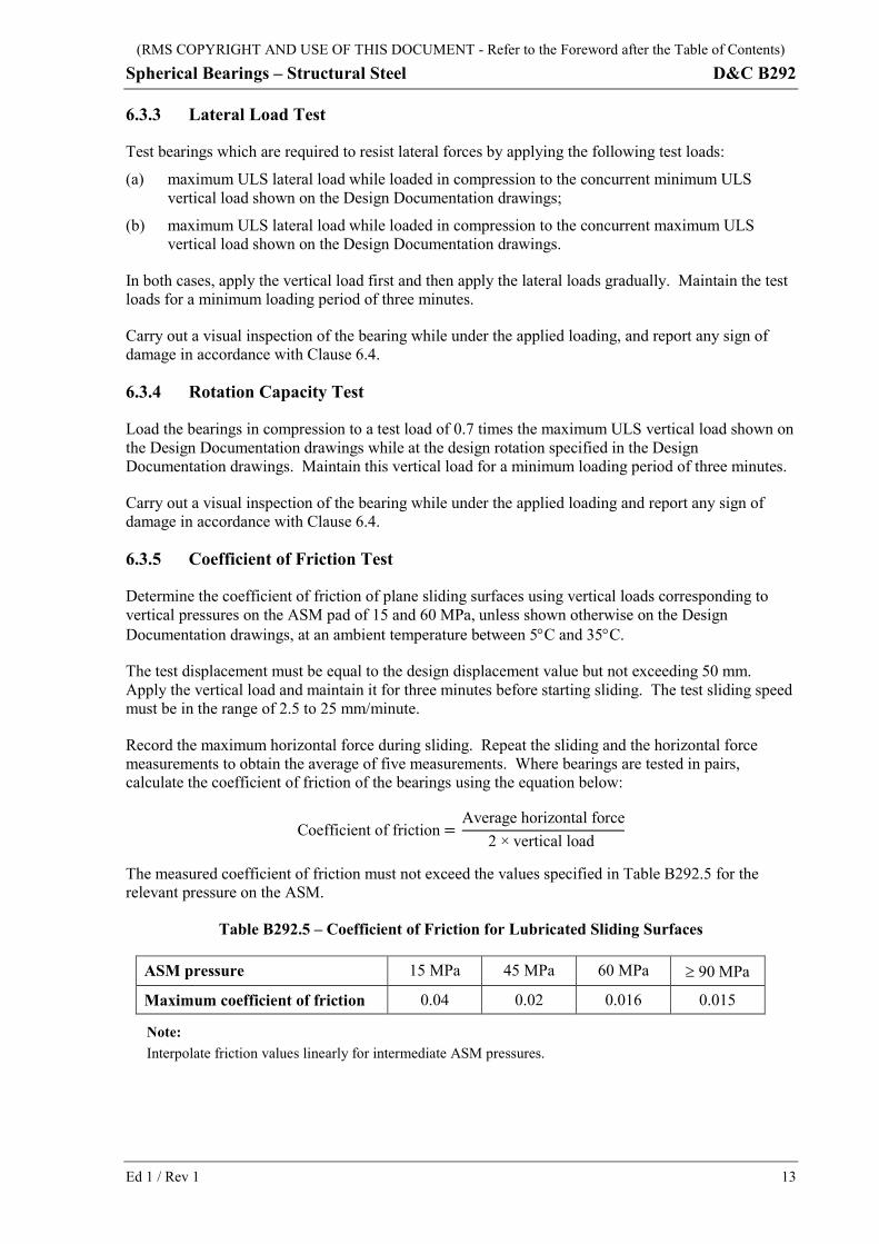
6.3.5 Coefficient of Friction Test
Determine the coefficient of friction of plane sliding surfaces using vertical loads corresponding to vertical pressures on the ASM pad of 15 and 60 MPa, unless shown otherwise on the Design Documentation drawings, at an ambient temperature between 5°C and 35°C.
The test displacement must be equal to the design displacement value but not exceeding 50 mm. Apply the vertical load and maintain it for three minutes before starting sliding. The test sliding speed must be in the range of 2.5 to 25 mm/minute.
Record the maximum horizontal force during sliding. Repeat the sliding and the horizontal force measurements to obtain the average of five measurements. Where bearings are tested in pairs, calculate the coefficient of friction of the bearings using the equation below:
Coefficient of friction = Average horizontal force
2 × vertical load
The measured coefficient of friction must not exceed the values specified in Table B292.5 for the relevant pressure on the ASM.
Table B292.5 – Coefficient of Friction for Lubricated Sliding Surfaces
ASM pressure 15 MPa 45 MPa 60 MPa ≥ 90 MPa
Maximum coefficient of friction 0.04 0.02 0.016 0.015
Note: Interpolate friction values linearly for intermediate ASM pressures.
(RMS COPYRIGHT AND USE OF THIS DOCUMENT - Refer to the Foreword after the Table of Contents)
D&C B292 Spherical Bearings – Structural Steel
14 Ed 1 / Rev 1
6.4 CRITERIA FOR ACCEPTANCE
6.4.1 General
Reject any bearing that does not meet the requirements of the geometrical verification in Clause 6.2 or any of the load tests in Clause 6.3, or exhibits any signs of damage during or after the testing.
Such signs of damage include:
(a) tearing, cracking or excessive deformation of the sliding surfaces;
(b) cracking, indentation or permanent deformation of any part of the bearing;
(c) abrasive marks indicating abnormal contact between the metal surfaces of the bearing;
(d) failure or permanent deformations of guide bars;
(e) damage to chromium plating where applicable.
6.4.2 Acceptance of Remainder
If a bearing is rejected, test two additional bearings from the group of bearing represented by the failed bearing. If both bearings meet the requirements of this Specification, the RMS Representative may accept the remaining bearings in the bearing group. Should one or both of the bearings not meet the requirements of this Specification, test each of the remaining bearings in the group for compliance.
6.5 BEARING REPORT
Provide a bearing report verifying that all bearings conform to the requirements of this Specification. The report must include:
(a) a summary of all test results with clear identification of the bearings tested;
(b) geometrical verification of all bearing dimensions;
(c) protective treatment certification.
7 IDENTIFICATION AND DELIVERY
7.1 IDENTIFICATION
Identify each bearing and fit a name plate to the bearing in accordance with AS 5100.4. Indicate the applicable installation locations of the bearings.
Ensure that the bearing orientation, the centreline and the direction(s) of movement as appropriate are readily identifiable to facilitate correct placement.

(RMS COPYRIGHT AND USE OF THIS DOCUMENT - Refer to the Foreword after the Table of Contents)
Spherical Bearings – Structural Steel D&C B292
Ed 1 / Rev 1 15
7.2 DELIVERY
HOLD POINT
Process Held: Delivery of bearings to site.
Submission Details: Bearing test report in accordance with Clause 6.5, at least 10 working days before the proposed date for delivery of bearings to site.
Release of Hold Point: The Nominated Authority will consider the submitted documents for compliance with this Specification, prior to authorising the release of the Hold Point.
Provide temporary transit clips or equivalent, which must be easily removable, to hold the bearing components assembled during delivery. Do not remove the transit clips and/or bolts until after completion of installation in the bridge structure.
Supply mating parts of bearings in sets held together at the correct preset and skew with metal transit clips and/or bolts to prevent misalignment and/or damage of the components during transport and erection.
Protect bearings in dust and moisture resistant wrappings after assembly and during transportation to site and keep them secured in a horizontal condition.

(RMS COPYRIGHT AND USE OF THIS DOCUMENT - Refer to the Foreword after the Table of Contents)
D&C B292 Spherical Bearings – Structural Steel
16 Ed 1 / Rev 1
ANNEXURE B292/A – JOB SPECIFIC REQUIREMENTS Refer to Clause 1.2.1.
Paint System Colour of Paint Coat
ANNEXURE B292/B – (NOT USED)

(RMS COPYRIGHT AND USE OF THIS DOCUMENT - Refer to the Foreword after the Table of Contents)
Spherical Bearings – Structural Steel D&C B292
Ed 1 / Rev 1 17
ANNEXURE B292/C – SCHEDULES OF HOLD POINTS AND IDENTIFIED RECORDS
Refer to Clause 1.2.3.
C1 SCHEDULE OF HOLD POINTS
Clause Point Description
4.1 Hold Submission of planning documents
7.2 Hold Submission of bearing report
C2 SCHEDULE OF IDENTIFIED RECORDS
The records listed below are Identified Records for the purposes of RMS D&C Q6 Annexure Q/E.
Clause Description of the Identified Record
2.2 Bearing design calculations, drawings and certification
2.2 Any variations from the previously approved bearing details
3.5 Documentary evidence of materials conformity
5.1 Protective treatment details
6.5 Bearing report
ANNEXURE B292/D – PLANNING DOCUMENTS Refer to Clause 1.2.4.
The following documents are a summary of documents that must be included in the PROJECT QUALITY PLAN. Review the requirements of this Specification and other deed documents to determine any additional documentation requirements.
Clause Description of Document
4.5.2 Technical procedure for welding of stainless steel sheet
4.7 Technical procedure for lubricating the ASM pad
5 Technical procedures for protective treatment
6.1 Technical procedure for dismantling and reassembly of test bearings

(RMS COPYRIGHT AND USE OF THIS DOCUMENT - Refer to the Foreword after the Table of Contents)
D&C B292 Spherical Bearings – Structural Steel
18 Ed 1 / Rev 1
ANNEXURE B292/E – ZP COATING SYSTEM
E1 Coating System
Coating system consists of zinc coat, sealer and wet paint coating applied in their respective order.
E2 Surface Preparation (a) Abrasive blast cleaned to Class 3 in accordance with AS 1627.4.
(b) Nominal surface profile of 75µm.
(c) Surface profile measured in accordance with Method A in AS 3894.5.
E3 Zinc Coat (a) Zinc wire: Zn 99.99 conforming to ISO 752.
(a) Minimum local thickness of 150 µm.
(b) Local coat thickness measured in accordance with AS 2331.1.3.
E4 Sealer (a) Sealer: a proprietary low viscosity sealer compatible with the top coat.
E5 Wet Paint Coating Systems (a) Wet paint coating systems must be either System A or System B in accordance with
Table B292/E.1.
Table B292/E.1 – Wet Paint Coating Properties
Description System A System B
Paint MIO epoxy HB polyurethane
Min DFT (µm) 125 125
Colour RMS Bridge Grey to Colours for Micaceous Iron Oxide Pigmented Paints, produced by the NSW State Paint Group of the Government Paint Committee, June 1993
Colour N35 “Light Grey” to AS 2700
(b) System A is the default system.
(c) System B is only applied where so specified in Annexure B292/A or as shown on the Design Documentation drawings as a job specific requirement.
(d) MIO epoxy: a two pack micaceous iron oxide pigmented polyamide cured epoxy coating conforming to APAS 2972.
(e) HB polyurethane: a full gloss two component, high build recoatable, acrylic modified polyurethane enamel, excluding two pack acrylic, included in a system conforming to APAS 2911.
(f) Minimum DFT is the minimum dry film thickness measured in accordance with Magnetic Induction Method B in AS 3894.3.
ANNEXURES B292/F TO B292/K– (NOT USED)

(RMS COPYRIGHT AND USE OF THIS DOCUMENT - Refer to the Foreword after the Table of Contents)
Spherical Bearings – Structural Steel D&C B292
Ed 1 / Rev 1 19
ANNEXURE B292/L – MINIMUM FREQUENCY OF TESTING Refer to Clause 1.2.5.
Table B292/L.1 – Frequency of Testing
Clause Type of Test Bearings per Group
≤ 10 > 10 and ≤ 25 > 25
6.2 Geometrical verification All
6.3.2 Vertical load test
6.3.3 Lateral load test 1 per group 2 per group 3 per group
6.3.4 Rotation capacity test
6.3.5 Coefficient of friction test 1 per stainless steel batch and ASM batch combination (1)
Notes: (1) The test results are only valid where the stainless steel batch and ASM batch combination tested is the same
as that used for the bearings represented by the test sample. Past test results not more than two years old obtained for previous projects for the same ASM and stainless steel batches may be accepted by the RMS Representative.

(RMS COPYRIGHT AND USE OF THIS DOCUMENT - Refer to the Foreword after the Table of Contents)
D&C B292 Spherical Bearings – Structural Steel
20 Ed 1 / Rev 1
ANNEXURE B292/M – REFERENCED DOCUMENTS Refer to Clause 1.2.6.
RMS Specifications
RMS D&C Q6 Quality Management System (Type 6)
RMS D&C B201 Steelwork for Bridges
RMS D&C B240 Supply of Bolts, Nuts, Screws and Washers
RMS D&C B284 Installation of Bridge Bearings
Australian Standards
AS/NZS 1214 Hot-dip galvanized coatings on threaded fasteners (ISO metric coarse thread series)
AS/NZS 1554.6 Structural steel welding - Welding stainless steels for structural purposes
AS 1627 Metal finishing – Preparation and pretreatment of surfaces
AS 1627.1 Part 1: Removal of oil, grease and related contamination
AS 1627.4 Part 4: Abrasive blast cleaning
AS/NZS 2312 Guide to the protection of structural steel against atmospheric corrosion by the use of protective coatings
AS/NZS 2312.1 Part 1: Paint coatings
AS/NZS 2312.2 Part 2: Hot dip galvanizing
AS 2331 Methods of test for metallic and related coatings
AS 2331.1.3 Method 1.3: Local thickness tests – Magnetic method
AS 2331.3.9 Method 3.9: Corrosion and related property tests - Metallic coatings - Porosity tests - Ferroxyl test
AS 2453 Electroplated coatings - Chromium for engineering applications
AS 2700 Colour standards for general purposes
AS/NZS 3678 Structural steel - Hot-rolled plates, floorplates and slabs
AS/NZS 3679.1 Structural steel - Hot-rolled bars and sections
AS 3894 Site testing of protective coating
AS 3894.3 Part 3: Determination of dry film thickness
AS 3894.5 Part 5: Determination of surface profile
AS/NZS 4680 Hot-dip galvanized (zinc) coatings on fabricated ferrous articles
AS 5100 Bridge design
AS 5100.2 Part 2: Design loads
AS 5100.4 Part 4: Bearings and deck joints
AS 5100.6 Part 6: Steel and composite construction
AS/NZS ISO 9001 Quality management systems – Requirements

(RMS COPYRIGHT AND USE OF THIS DOCUMENT - Refer to the Foreword after the Table of Contents)
Spherical Bearings – Structural Steel D&C B292
Ed 1 / Rev 1 21
Other Standards
ASTM A240M Standard specification for chromium and chromium-nickel stainless steel plate, sheet, and strip for pressure vessels and for general applications
ASTM C794 Standard test method for adhesion-in-peel of elastomeric joint sealants
ASTM D217 Standard test methods for cone penetration of lubricating grease
ASTM D972 Standard test method for evaporation loss of lubricating greases and oils
EN 1337-2 Structural bearings. Sliding elements
ISO 752 Zinc ingots
ISO 3274 Geometrical Product Specifications (GPS) – Surface texture: Profile method – Nominal characteristics of contact (stylus) instruments
ISO 4287 Geometrical Product Specifications (GPS) – Surface texture: Profile method – Terms, definitions and surface texture parameters
APAS Specifications
APAS 2911 Polyurethane coating for protection of steel
APAS 2972 Low build epoxy two-pack coating for the long term protection of steel in atmosphere