day one: securing the routing engine · day one: securing the routing engine on m, ... firewall...
TRANSCRIPT
Junos® Fundamentals Series
Apply the powerful policy tools of
Junos essential to protecting your
device and your whole network with
expert, step-by-step techniques.
By Douglas Hanks Jr.
DAY ONE: SECURING THE ROUTING ENGINE ON M, MX, AND T SERIES
Juniper Networks Day One books provide just the information you need to know on day one. That’s because they are written by subject matter experts who specialize in getting networks up and running. Visit www.juniper.net/dayone to peruse the complete library.
Published by Juniper Networks Books
DAY ONE: SECURING THE ROUTING ENGINE ON M, MX, AND T SERIES
The routing engine on Junos routers performs many different functions, from processing routing protocol updates, to driving the command-line interface (CLI). Given that the routing engine is critical to the operation of the device and its network, you need to pro-tect the routing engine from unwanted traffic by allowing only essential permitted traf-fic. Unwanted traffic can come in many different forms: malicious traffic seeking to gain unauthorized access, unintentional routing protocol updates from neighboring devices, or even legitimate traffic that exceeds a given bandwidth limit.
This Day One book shows you how to secure the routing engine step-by-step. Learn how, learn why, then follow along as you build a modular firewall filter and apply it.
IT’S DAY ONE AND YOU HAVE A JOB TO DO, SO LEARN HOW TO:
Secure the routing engine with a modular framework of firewall policies and policers.
Understand how firewall filters work and how they are applied to the routing engine.
Create a modular framework by chaining together firewall filters.
Describe how firewall logs are managed and view firewall logs in detail.
Understand how firewall counters work and view firewall counters.
Write detailed firewall policies to permit specific traffic to the routing engine.
Build dynamic prefix-lists based off the Junos configuration using apply-path.
Rate-limit and police certain types of traffic to the routing engine.
Create filter-specific and term-specific policers.
“An indispensable resource for anyone who needs to protect their Internet connected routers.”
Matt Hite, Network Engineer, Zynga
ISBN 978-1-936779-28-4
9 781936 779284
5 2 2 0 0
07500212
Day One: Securing the Routing Engine
on M, MX, and T Series
By Douglas Hanks Jr.
Junos® Fundamentals Series
Firewall Filters . . . . . . . . . . . . . . . . . . . . . . . . . . . . . . . . . . . . . . . . . . . . . . . . . . . . . 7
Policers . . . . . . . . . . . . . . . . . . . . . . . . . . . . . . . . . . . . . . . . . . . . . . . . . . . . . . . . . . 27
Viewing Counters, Logs, and Policers . . . . . . . . . . . . . . . . . . . . . . . . . . . . . .39
Junos Configuration Automation . . . . . . . . . . . . . . . . . . . . . . . . . . . . . . . . . .49
Creating a Basic Framework of Firewall Filters . . . . . . . . . . . . . . . . . . . . .59
Applying Security Policies to the Routing Engine . . . . . . . . . . . . . . . . . . 99
Appendix . . . . . . . . . . . . . . . . . . . . . . . . . . . . . . . . . . . . . . . . . . . . . . . . . . . . . . . 123
© 2011 by Juniper Networks, Inc. All rights reserved.
Juniper Networks, the Juniper Networks logo, Junos, NetScreen, and ScreenOS are registered trademarks of Juniper Networks, Inc. in the United States and other countries. Junose is a trademark of Juniper Networks, Inc. All other trademarks, service marks, registered trademarks, or registered service marks are the property of their respective owners.
Juniper Networks assumes no responsibility for any inaccuracies in this document. Juniper Networks reserves the right to change, modify, transfer, or otherwise revise this publication without notice. Products made or sold by Juniper Networks or components thereof might be covered by one or more of the following patents that are owned by or licensed to Juniper Networks: U.S. Patent Nos. 5,473,599, 5,905,725, 5,909,440, 6,192,051, 6,333,650, 6,359,479, 6,406,312, 6,429,706, 6,459,579, 6,493,347, 6,538,518, 6,538,899, 6,552,918, 6,567,902, 6,578,186, and 6,590,785.
Published by Juniper Networks BooksAuthor: Douglas Hanks Jr.Technical Reviewers: Zaid Hammoudi, Chris Grunde-mann, Matt Hite, Richard FaircloughEditor in Chief: Patrick AmesCopyeditor and Proofer: Nancy KoerbelJunos Product Manager: Cathy GadeckiJ-Net Community Manager: Julie Wider
About the AuthorDouglas Hanks Jr. is a Sr. Systems Engineer with Juniper Networks. He is certified in Juniper Networks as JNCIE-ENT #213 and JNCIE-SP #875. Douglas’ interests are network engineering and architecture for both Enterprise and Service Provider routing and switching.
Author’s AcknowledgmentsI would like to thank my family for all their love and encouragement. This book is dedicated to Janice and Warisara. Thank you Patrick Ames and Cathy Gadecki for making this book possible. Thanks to Zaid Hammoudi, Chris Grundemann, Matt Hite, and Richard Fairclough for their technical review.
ISBN: 978-1-936779-28-4 (print)Printed in the USA by Vervante Corporation.
ISBN: 978-1-936779-29-1 (ebook)
Version History: v1 June 2011 2 3 4 5 6 7 8 9 10 #7100212-en
This book is available in a variety of formats at: www.juniper.net/dayone.
Send your suggestions, comments, and critiques by email to [email protected].
Follow the Day One series on Twitter: @Day1Junos
ii
What You Need to Know Before Reading this Book
�� The reader is expected to have previous hands-on experience working with the Junos operating system and network devices. The majority of this book deals with actual Junos configuration.
�� It’s beneficial, though not required, for the reader to hold a JNCIA-Junos certification from Juniper Networks. Topics in this book build on the basics found in the JNCIA-Junos material and extend into the intermediate to expert level of configuration.
�� An understanding of the services and protocols required to operate your network is necessary. Depending on the function and role of your router, these services and protocols may change. For exam-ple, a core router in an enterprise data center may be running OSPF, BFD, and VRRP, whereas an edge router may be running OSPF and BGP.
�� A general understanding of Layer 4 protocols such as TCP and UDP is also important. This book focuses heavily on segment fields such as source port, destination port, and flags.
After Reading this Book, You’ll Be Able to...
�� Secure the routing engine using a modular framework of firewall policies and policers.
�� Understand how firewall filters work and how they are applied to the routing engine.
�� Create a modular framework by chaining together firewall filters.
�� Understand how firewall logs are managed and view them in detail.
�� Understand how firewall counters work and view them.
�� Write detailed firewall policies to permit specific traffic to the routing engine.
�� Build dynamic prefix-lists based on the Junos configuration using the apply-path feature.
�� Omit large sections of the Junos configuration using the apply-flags feature.
�� Rate-limit and police certain types of traffic to the routing engine.
�� Create filter-specific and term-specific policers.
iii
iv
Why Secure the Routing Engine?
The routing engine performs many different functions, from process-ing routing protocol updates, to driving the command-line interface (CLI). Given that the routing engine is critical for the operation of the router and the network, the routing engine needs to be protected from unwanted traffic and to only allow traffic that it’s going to be interested in. Unwanted traffic comes in many different forms: malicious traffic seeking to gain unauthorized access, unintentional routing protocol updates from neighboring devices, or even legitimate traffic that exceeds a given bandwidth limit.
Routers are deployed in a variety of different scenarios and it’s com-mon that no two routers are alike, even within the same network. For instance, a router could be deployed in any of the following deploy-ment scenarios:
�� Service Provider core, aggregation, and edge.
�� Internet transit and peering.
�� Enterprise data center and demilitarized zone (DMZ).
�� Inter-data center transport.
Each of these deployment scenarios represents different networking requirements in terms of security, protocols, and services, making the creation and maintenance of customized security policies for each router a daunting task.
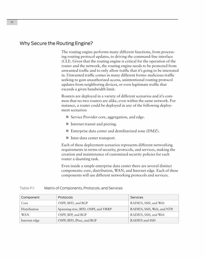
Even inside a simple enterprise data center there are several distinct components: core, distribution, WAN, and Internet edge. Each of these components will use different networking protocols and services.
Table�P.1 MatrixofComponents,Protocols,andServices
Component Protocols Services
Core OSPF, BFD, and BGP RADIUS, SSH, and Web
Distribution Spanning-tree, BFD, OSPF, and VRRP RADIUS, SSH, Web, and NTP.
WAN OSPF, BFP, and BGP RADIUS, SSH, and Web
Internet edge OSPF, BFD, IPsec, and BGP RADIUS and SSH
v
Traditionally, many network administrators have tried to maintain a protect-router ACL / firewall filter template for each type of router, and this quickly becomes an operational burden because creating a customized firewall filter for each router is time consuming. The “protect-router” firewall filter becomes so complex, and so large, that it makes the management more difficult as the administrator scales the network, or adds new services. As networking services such as RA-DIUS servers or BGP peers change over time, the protect-router ACL / firewall filter needs to be updated to reflect these changes.
It’s possible to create a simple security framework to support a wide variety of protocols and services by leveraging the power of the Junos operating system. This book illustrates simple building blocks based on commonly used protocols and services to make securing the routing engine an easy task: simply pick and choose what protocols and services are required for each router. Junos has configuration automation tools that enable dynamic prefix lists, and as your net-work scales and changes, the security framework automatically changes and adjusts without requiring additional input from the administrator.
Day One: Securing the Routing Engine on M/T/MX Series walks you through all the components and instructions on how to create a framework of firewall filters and policies to secure the routing engine, and in the final chapter you are presented with a final framework and configuration, which you can then implement on a router.
M/MX/T Routers
This book is geared towards the Juniper M/MX/T family of routers as they are most often deployed in very demanding environments. The amount of unwanted ingress traffic from the Internet is unbelievable. The router is constantly flooded with ICMP fragments, SSH login requests, file sharing protocols, and much more. In environments where all traffic must be treated as untrusted, it’s essential that the routing engine is secured against unwanted traffic.
NOTE Juniper has newly released a high-performance, mid-range series of MX routers: MX5, MX10, and the MX40. While not used in the test bed for this book, everything in this book applies to the new devices. For more information about the new line of mid-range Juniper MX routers see http://www.juniper.net/us/en/products-services/routing/mx-series/.

vi
Chapter 1
Firewall Filters
Firewall Families . . . . . . . . . . . . . . . . . . . . . . . . . . . . . . . . . . . . . . . . . . . . . . . . . .8
How Firewall Filters are Evaluated . . . . . . . . . . . . . . . . . . . . . . . . . . . . . . . . . .9
Firewall Filter Match Conditions . . . . . . . . . . . . . . . . . . . . . . . . . . . . . . . . . . . .11
Firewall Filter Actions . . . . . . . . . . . . . . . . . . . . . . . . . . . . . . . . . . . . . . . . . . . . . 12 Applying Firewall Filters . . . . . . . . . . . . . . . . . . . . . . . . . . . . . . . . . . . . . . . . . . . 18
Firewall Filters: Data Plane versus Control Plane . . . . . . . . . . . . . . . . . . . 21
Firewall Filter Chaining . . . . . . . . . . . . . . . . . . . . . . . . . . . . . . . . . . . . . . . . . . . .23
Nested Firewall Filters . . . . . . . . . . . . . . . . . . . . . . . . . . . . . . . . . . . . . . . . . . . .25
Summary . . . . . . . . . . . . . . . . . . . . . . . . . . . . . . . . . . . . . . . . . . . . . . . . . . . . . . . .26
8 DayOne:SecuringtheRoutingEngineonM,MX,andTSeries
The primary method of matching traffic and performing an action is performed with a firewall filter, and Chapter 1 details what firewall filters are and how to use them. A firewall filter can be applied to traffic in two directions: input and output. Input refers to traffic destined for the routing engine if applied to the control plane, or ingress traffic to a logical interface if applied to the data plane. Likewise, output refers to traffic sourced from the routing engine if applied to the control plane, or egress traffic from a logical interface if applied to the data plane.
This may seem a little confusing now, but once you walk through a few instances it becomes clear.
Firewall filters are used to match traffic and perform an action on the traffic matched, very similar to a policy statement. Firewall filters consist of one or more named terms and each term has a set of match conditions, and a set of actions or non-terminating actions. If no traffic is matched by any of the terms there is a hidden implicit-rule that discards all traffic. Here’s the firewall filter configuration syntax:
[edit firewall family inet]filter filter-name { term term-name { from { match-conditions; } then { action; nonterminating-actions; } } term implicit-rule { then discard; }}
Firewall Families
Firewall filters are defined differently for different protocol family types and filters that are defined for a specific family type can only be applied to an interface using the same protocol family. For example, a firewall defined as family inet can only be applied to an interface under family inet. Table 1.1 lists some of the types of protocol families for firewall filters.
Chapter1:FirewallFilters 9
Table�1.1� FirewallFilterProtocolFamilyTypes
Protocol Family Description
any Protocol-independent filter.
bridge Protocol family bridge.
ccc Protocol family circuit cross-connect.
inet Protocol family IPv4.
inet6 Protocol family IPv6.
mpls Protocol family MultiProtocol Label Switching.
vpls Protocol family Virtual Private LAN Service.
NOTE� This book focuses strictly on IPv4 or family inet. For more informa-tion about Junos and IPv6, see the Day One books about IPv6 at http://www.juniper.net/dayone.
How Firewall Filters are Evaluated
Firewall filters are evaluated from the top-down starting with the first term within the filter. If no matches are found within a term, the next term is evaluated until a match is found. If a match isn’t found then the hidden implicit-rule at the end of the firewall filter discards the traffic.
Single-termFilters
If a firewall filter contains a single term, it is evaluated starting with the from statement. If there is a match, the action specified in the then statement is taken. If there is no match, the traffic is discarded. For example:
[firewall family inet]filter example-filter { term single-term { from { source-address 10.0.0.0/8; } then { accept; } }}
You can see in the firewall filter that there is a single term. If the packet has a source address of 10/8 it is accepted, and if there is no match, then the hidden implicit-rule discards the packet.
10 DayOne:SecuringtheRoutingEngineonM,MX,andTSeries
Multiple-term Filters
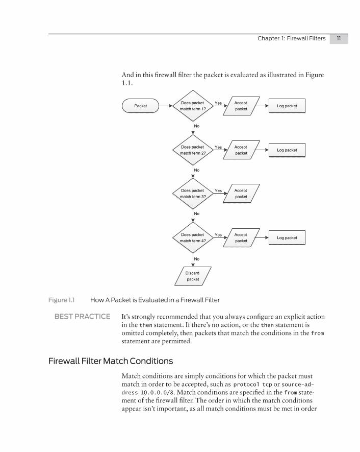
If the firewall filter has more than a single term, the filter is evaluated from the top-down starting with the first term. It’s common to see term names in Junos documentation in ascending order such as term 1, term 2, and term 3. However, regardless of the name, the filter is always evaluated sequentially, top-down, until a match occurs. If there is a match, the action specified in the then statement is taken. If there is no match, the next term is evaluated. This process continues until there is a match or there are no more terms left to evaluate. If a packet passes all the way through a filter without matching any of the terms, the hidden implicit-rule at the end of the term discards the packet.
If a packet matches the conditions in the from statement and the term doesn’t contain a then statement, or doesn’t have an action defined, the packet is accepted by default. Here’s an example of a filter with several terms:
[firewall family inet]filter example-filter { term 1 { from { source-address 10.0.0.0/8; } then { log; accept; } } term 2 { from { source-address 192.168.0.0/16; } then { accept; } } term 3 { from { source-address 172.16.0.0/12; } term 4 { from { source-address 200.200.0.0/24; } then { log; }}
Chapter1:FirewallFilters 11
And in this firewall filter the packet is evaluated as illustrated in Figure 1.1.
PacketAccept packet
Discard packet
YesDoes packet match term 1?
Accept packet
Does packet match term 2?
Accept packet
Does packet match term 3?
Does packet match term 4?
Accept packet
Yes
Yes
Yes
No
No
No
No
Log packet
Log packet
Log packet
Figure�1.1 HowAPacketisEvaluatedinaFirewallFilter
BEST�PRACTICE It’s strongly recommended that you always configure an explicit action in the then statement. If there’s no action, or the then statement is omitted completely, then packets that match the conditions in the from statement are permitted.
Firewall Filter Match Conditions
Match conditions are simply conditions for which the packet must match in order to be accepted, such as protocol tcp or source-ad-dress 10.0.0.0/8. Match conditions are specified in the from state-ment of the firewall filter. The order in which the match conditions appear isn’t important, as all match conditions must be met in order
12 DayOne:SecuringtheRoutingEngineonM,MX,andTSeries
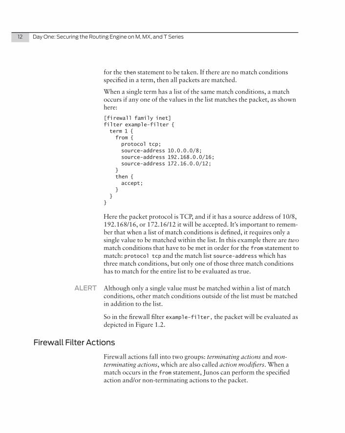
for the then statement to be taken. If there are no match conditions specified in a term, then all packets are matched.
When a single term has a list of the same match conditions, a match occurs if any one of the values in the list matches the packet, as shown here:
[firewall family inet]filter example-filter { term 1 { from { protocol tcp; source-address 10.0.0.0/8; source-address 192.168.0.0/16; source-address 172.16.0.0/12; } then { accept; } }}
Here the packet protocol is TCP, and if it has a source address of 10/8, 192.168/16, or 172.16/12 it will be accepted. It’s important to remem-ber that when a list of match conditions is defined, it requires only a single value to be matched within the list. In this example there are two match conditions that have to be met in order for the from statement to match: protocol tcp and the match list source-address which has three match conditions, but only one of those three match conditions has to match for the entire list to be evaluated as true.
ALERT Although only a single value must be matched within a list of match conditions, other match conditions outside of the list must be matched in addition to the list.
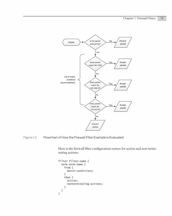
So in the firewall filter example-filter, the packet will be evaluated as depicted in Figure 1.2.
Firewall Filter Actions
Firewall actions fall into two groups: terminating actions and non-terminating actions, which are also called action modifiers. When a match occurs in the from statement, Junos can perform the specified action and/or non-terminating actions to the packet.
Chapter1:FirewallFilters 13
Packet
Accept packet
Discard
packet
YesDoes packet
match SA 10/8?
Accept packet
Does packet
match SA
192.168/16?
Accept packet
Does packet
match SA
172.16/12?
Yes
Yes
No
No
No
Is the packet
protocol tcp?
Discard packet
No
Yes
List of match conditions
(source-address)
Figure�1.2 FlowchartofHowtheFirewallFilterExampleisEvaluated
Here is the firewall filter configuration syntax for action and non-termi-nating actions:
filter filter-name { term term-name { from { match-conditions; } then { action; nonterminating-actions; } }}
14 DayOne:SecuringtheRoutingEngineonM,MX,andTSeries
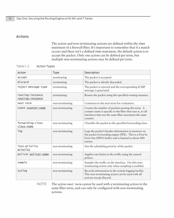
Actions
The action and non-terminating actions are defined within the then statement of a firewall filter. It’s important to remember that if a match occurs and there isn’t a defined then statement, the default action is to accept the packet. Only one action can be defined per term, but multiple non-terminating actions may be defined per term.
Table�1.�2 ActionTypes
Action Type Description
accept terminating The packet is accepted.
discard terminating The packet is silently discarded.
reject message-type terminating The packet is rejected and the corresponding ICMP message is generated.
routing-instance routing-instance
terminating Routes the packet using the specified routing-instance.
next term non-terminating Continues to the next term for evaluation.
count counter-name non-terminating Counts the number of packets passing this term. A counter name is specific to the filter that uses it, so all interfaces that use the same filter increment the same counter.
forwarding-class class-name
non-terminating Classifies the packet to the specified forwarding class.
log non-terminating Logs the packet’s header information in memory on the packet forwarding engine (PFE). This is a First In First Out (FIFO) buffer and is limited to about 400 entries.
loss-priority priority
non-terminating Sets the scheduling priority of the packet.
policer policer-name non-terminating Applies rate limits to the traffic using the named policer.
sample non-terminating Samples the traffic on the interface. Use this non-terminating action only when sampling is enabled.
syslog non-terminating Records information in the system logging facility. This non-terminating action can be used with all actions except discard.
NOTE The action next term cannot be used with a terminating action in the same filter term, and can only be configured with non-terminating actions.
Chapter1:FirewallFilters 15
MORE? This book only deals with actions: accept, reject, discard, count, log, and policer. For more information on the other actions visit http://www.juniper.net/techpubs/en_US/junos10.4/topics/usage-guidelines/policy-configuring-actions-in-firewall-filter-terms.html.
The action accept is the most commonly used because the default action of a firewall filter is to discard all traffic that isn’t matched. If the objective is to match certain packets and deny them, the most common action is discard. The discard action silently drops the packet without generating an ICMP message. This method has security benefits as the routing engine does not give any clues as to why the traffic was dropped. In certain situations it makes complete sense to match a packet and deny it and generate a corresponding ICMP message. The reject action discards the packet and generates and sends an ICMP administratively-prohibited message by default, but there are other ICMP messages than can be specified to override the default, such as:
�� administratively-prohibited (this is the default)
�� bad-host-tos
�� bad-network-tos
�� fragmentation-needed
�� host-prohibited
�� host-unknown
�� host-unreachable
�� network-prohibited
�� network-unknown
�� network-unreachable
�� port-unreachable
�� precedence-cutoff
�� precedence-violation
�� source-host-isolated
�� source-route-failed
�� tcp-reset (If the original packet was TCP, a TCP reset segment is generated, and if the original packet wasn’t TCP, no response is generated.)
16 DayOne:SecuringtheRoutingEngineonM,MX,andTSeries
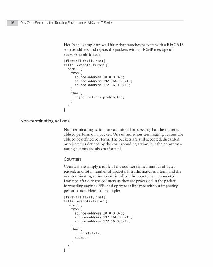
Here’s an example firewall filter that matches packets with a RFC1918 source address and rejects the packets with an ICMP message of network-prohibited:
[firewall family inet]filter example-filter { term 1 { from { source-address 10.0.0.0/8; source-address 192.168.0.0/16; source-address 172.16.0.0/12; } then { reject network-prohibited; } }
}
Non-terminating Actions
Non-terminating actions are additional processing that the router is able to perform on a packet. One or more non-terminating actions are able to be defined per term. The packets are still accepted, discarded, or rejected as defined by the corresponding action, but the non-termi-nating actions are also performed.
Counters
Counters are simply a tuple of the counter name, number of bytes passed, and total number of packets. If traffic matches a term and the non-terminating action count is called, the counter is incremented. Don’t be afraid to use counters as they are processed in the packet forwarding engine (PFE) and operate at line rate without impacting performance. Here’s an example:
[firewall family inet]filter example-filter { term 1 { from { source-address 10.0.0.0/8; source-address 192.168.0.0/16; source-address 172.16.0.0/12; } then { count rfc1918; accept; } }
}
Chapter1:FirewallFilters 17
The example firewall filter illustrates how to define a counter. Use the non-terminating action count followed by a name for the counter.
NOTE Counter names are aggregated by default. If there are multiple firewall filters using the same counter name, each counter will increment an aggregated counter name. To change this behavior so that counter names are aggregated per interface, use the interface-specific knob within the firewall filter.
NOTE There can only be a single counter defined per term.
Counters give instant visibility into how the firewall filter is working and are often used to detect mistakes in a firewall filter or abnormal traffic conditions. A common use of counters is to count the number of bytes and packets that have been discarded at the end of a firewall filter.
Logging
If you use the non-terminating action log, it records the packet’s header information and places it into a FIFO buffer on the PFE. This FIFO holds about 400 entries.
ALERT! The non-terminating action log is completely different from syslog. Although both log and syslog log the packet’s header, the non-termi-nating action log operates at line-rate, storing the information in PFE memory, whereas the non-terminating action syslog sends the packet’s header to the routing engine to be processed, which is subject to the internal routing engine policer.
Logging is a great tool to spot-check firewall filters without a loss in performance. It’s commonly used to log traffic that wasn’t matched in a firewall filter. Here’s a firewall filter example that defines logging by using the non-terminating action log:
[firewall family inet]filter example-filter { term 1 {º from { source-address 10.0.0.0/8; source-address 192.168.0.0/16; source-address 172.16.0.0/12; } then { accept; } }
18 DayOne:SecuringtheRoutingEngineonM,MX,andTSeries
term 2 { then { log; discard; } }}
If the packet has a RFC1918 source address it will be accepted. All other packets are discarded and logged to the PFE.
ALERT! You should use logging sparingly as all logs are placed into an in-memo-ry FIFO that only supports about 400 entries. If too much traffic is being logged, the FIFO rotates the logged traffic out so fast it isn’t useful.
NOTE There can only be one log per firewall term.
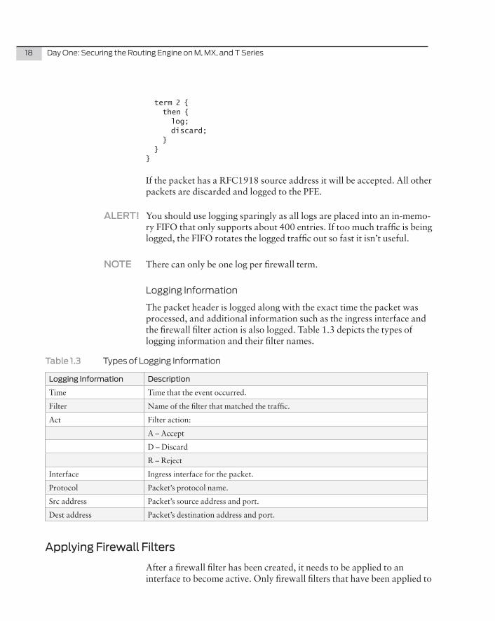
LoggingInformation
The packet header is logged along with the exact time the packet was processed, and additional information such as the ingress interface and the firewall filter action is also logged. Table 1.3 depicts the types of logging information and their filter names.
Table�1.3� TypesofLoggingInformation
Logging Information Description
Time Time that the event occurred.
Filter Name of the filter that matched the traffic.
Act Filter action:
A – Accept
D – Discard
R – Reject
Interface Ingress interface for the packet.
Protocol Packet’s protocol name.
Src address Packet’s source address and port.
Dest address Packet’s destination address and port.
Applying Firewall Filters
After a firewall filter has been created, it needs to be applied to an interface to become active. Only firewall filters that have been applied to
Chapter1:FirewallFilters 19
an interface are evaluated, and once applied, the filter is installed into the PFE and all processing is performed at line rate.
Direction
Firewall filters can be applied in two directions: input and output. Firewall filters applied with the direction of input match ingress traffic and firewall filters applied with the direction of output will match egress traffic.
To apply a firewall filter use the filter statement under the interface’s protocol family, specify the direction, then the firewall filter name.
Input:
# set interfaces lo0.0 family inet filter input example-filter
Output:
# set interfaces lo0.0 family inet filter output example-filter
NOTE Be careful applying firewall filters to the interface lo0.0. The firewall filter must account for all management and routing protocols that are used on the router. It’s recommended to always use the console or the command commit confirmed when applying firewall filters to the routing engine in case you accidentally lock yourself out.
How to Create a Firewall Filter
Let’s put all the pieces together and try creating our own firewall filter:
1. Begin by going into configure mode on your router.
dhanks@MX80> configure Entering configuration mode
2. Now, create and name the firewall filter example-filter with a single-term of 1 with a non-terminating action of log:
[edit]dhanks@MX80# set firewall family inet filter example-filter term 1 then log
3. Now create a counter called example-filter.
[edit]dhanks@MX80# set firewall family inet filter example-filter term 1 then count example-filter
4. Create a terminating action of accept:
[edit]dhanks@MX80# set firewall family inet filter example-filter term 1 then accept
20 DayOne:SecuringtheRoutingEngineonM,MX,andTSeries
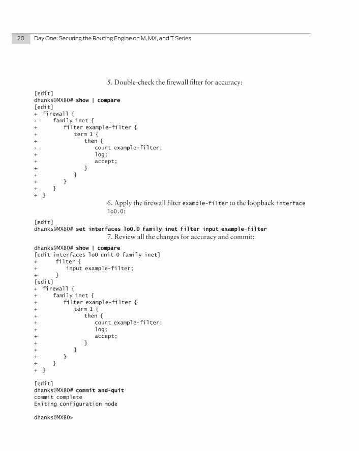
5. Double-check the firewall filter for accuracy:
[edit]dhanks@MX80# show | compare [edit]+ firewall {+ family inet {+ filter example-filter {+ term 1 {+ then {+ count example-filter;+ log;+ accept;+ }+ }+ }+ }+ }
6. Apply the firewall filter example-filter to the loopback interface lo0.0:
[edit]dhanks@MX80# set interfaces lo0.0 family inet filter input example-filter
7. Review all the changes for accuracy and commit:
dhanks@MX80# show | compare [edit interfaces lo0 unit 0 family inet]+ filter {+ input example-filter;+ }[edit]+ firewall {+ family inet {+ filter example-filter {+ term 1 {+ then {+ count example-filter;+ log;+ accept;+ }+ }+ }+ }+ }
[edit]dhanks@MX80# commit and-quit commit completeExiting configuration mode
dhanks@MX80>
Chapter1:FirewallFilters 21
ALERT! Always use the commit confirmed 5 command when applying firewall filters to the control plane via interface lo0.0. This commits the configuration to the router and if the command commit isn’t applied again within 5 minutes, the router automatically rollbacks to the previous configuration. This way if you make a mistake you haven’t locked yourself out.
TryItYourself:CreateYourOwnFilter
Although the firewall filter just completed may not particularly useful, it successfully demon-strates how to create a firewall filter with a single term and with both terminating and non-terminating actions. While Chapter 5 dives deep into firewall filters to protect the engine, including major routing protocols and management tools, try completing a few firewall filters now, for practice. Use the seven-step process and implement some of the terms, actions, and non-terminating actions discussed.
Firewall Filters: Data Plane versus Control Plane
Depending on where the firewall filter is applied, it will filter traffic on the data or control plane. If the firewall filter is applied to the inter-face lo0.0 it filters all control plane traffic:
interfaces { lo0 { unit 0 { family inet { filter {input accept-all; } address 127.0.0.1/32; } } ge-0/0/0 unit 0 { family inet { address 10.0.0.1/30; } }}firewall { family inet { filter accept-all { term 1 { then { count accept-all; log; accept;
22 DayOne:SecuringtheRoutingEngineonM,MX,andTSeries
} } } }}
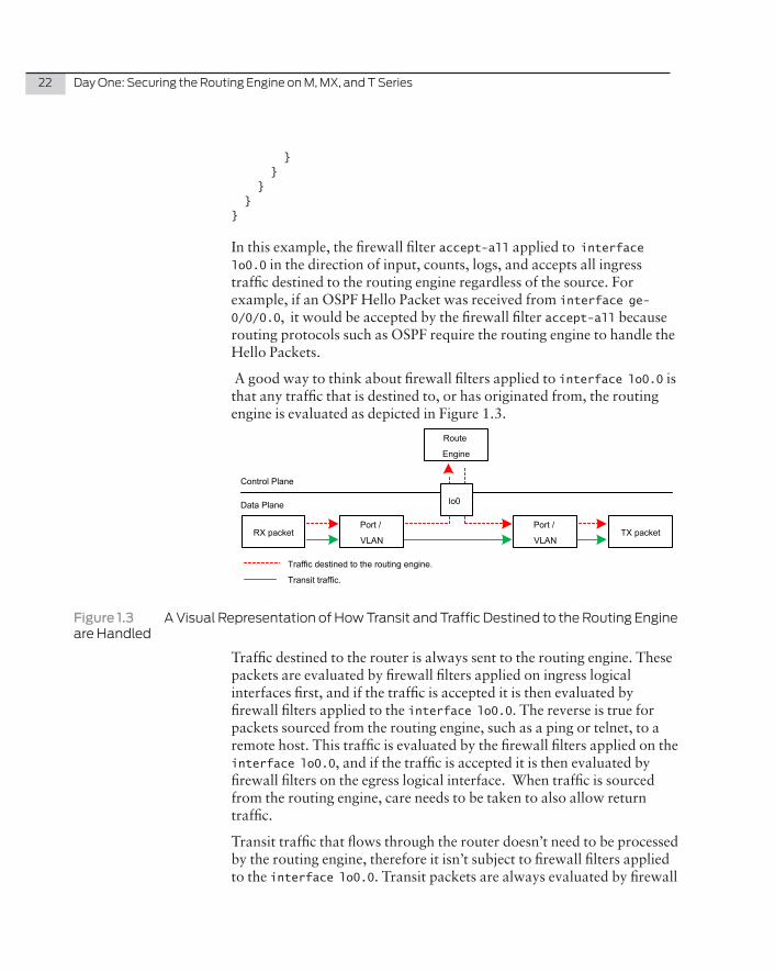
In this example, the firewall filter accept-all applied to interface lo0.0 in the direction of input, counts, logs, and accepts all ingress traffic destined to the routing engine regardless of the source. For example, if an OSPF Hello Packet was received from interface ge-0/0/0.0, it would be accepted by the firewall filter accept-all because routing protocols such as OSPF require the routing engine to handle the Hello Packets.
A good way to think about firewall filters applied to interface lo0.0 is that any traffic that is destined to, or has originated from, the routing engine is evaluated as depicted in Figure 1.3.
Control Plane
Data Plane
Traffic destined to the routing engine.
Transit traffic.
lo0
Route
Engine
Port /
VLANTX packetRX packet
Port /
VLAN
Figure�1.3 AVisualRepresentationofHowTransitandTrafficDestinedtotheRoutingEngineareHandled
Traffic destined to the router is always sent to the routing engine. These packets are evaluated by firewall filters applied on ingress logical interfaces first, and if the traffic is accepted it is then evaluated by firewall filters applied to the interface lo0.0. The reverse is true for packets sourced from the routing engine, such as a ping or telnet, to a remote host. This traffic is evaluated by the firewall filters applied on the interface lo0.0, and if the traffic is accepted it is then evaluated by firewall filters on the egress logical interface. When traffic is sourced from the routing engine, care needs to be taken to also allow return traffic.
Transit traffic that flows through the router doesn’t need to be processed by the routing engine, therefore it isn’t subject to firewall filters applied to the interface lo0.0. Transit packets are always evaluated by firewall
Chapter1:FirewallFilters 23
filters applied on the ingress logical interface first, and if accepted, will be subject to the applied egress filters.
Firewall Filter Chaining
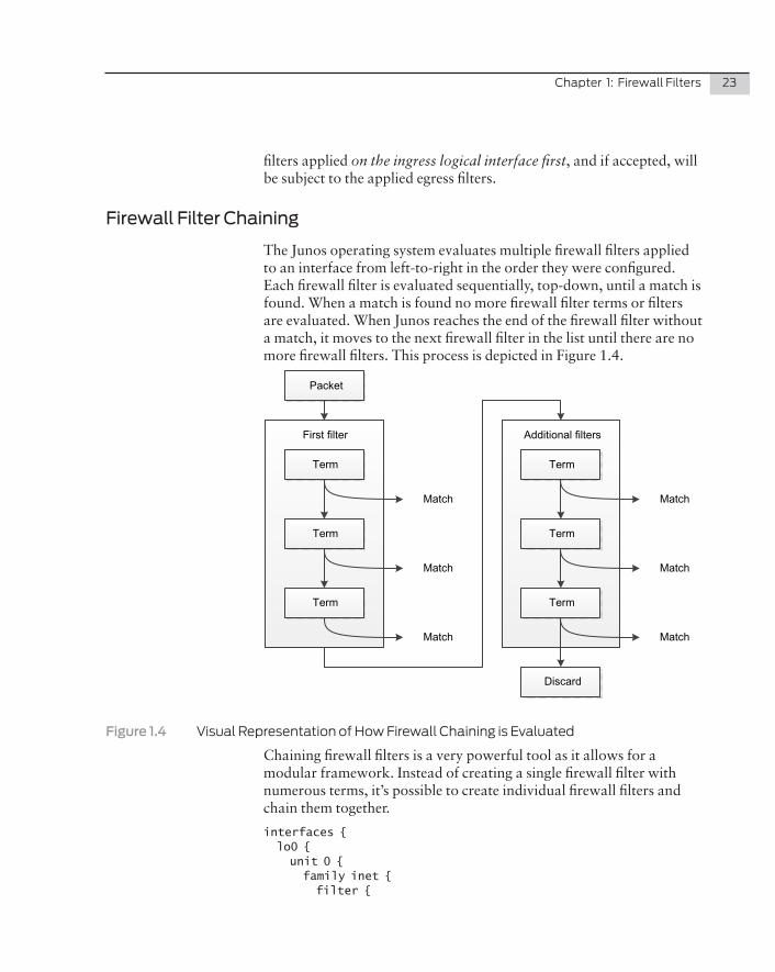
The Junos operating system evaluates multiple firewall filters applied to an interface from left-to-right in the order they were configured. Each firewall filter is evaluated sequentially, top-down, until a match is found. When a match is found no more firewall filter terms or filters are evaluated. When Junos reaches the end of the firewall filter without a match, it moves to the next firewall filter in the list until there are no more firewall filters. This process is depicted in Figure 1.4.
First filter
Packet
Term
Term
Term
Match
Match
Match
Additional filters
Term
Term
Term
Match
Match
Match
Discard
Figure�1.4� VisualRepresentationofHowFirewallChainingisEvaluated
Chaining firewall filters is a very powerful tool as it allows for a modular framework. Instead of creating a single firewall filter with numerous terms, it’s possible to create individual firewall filters and chain them together.
interfaces { lo0 { unit 0 { family inet { filter {
24 DayOne:SecuringtheRoutingEngineonM,MX,andTSeries
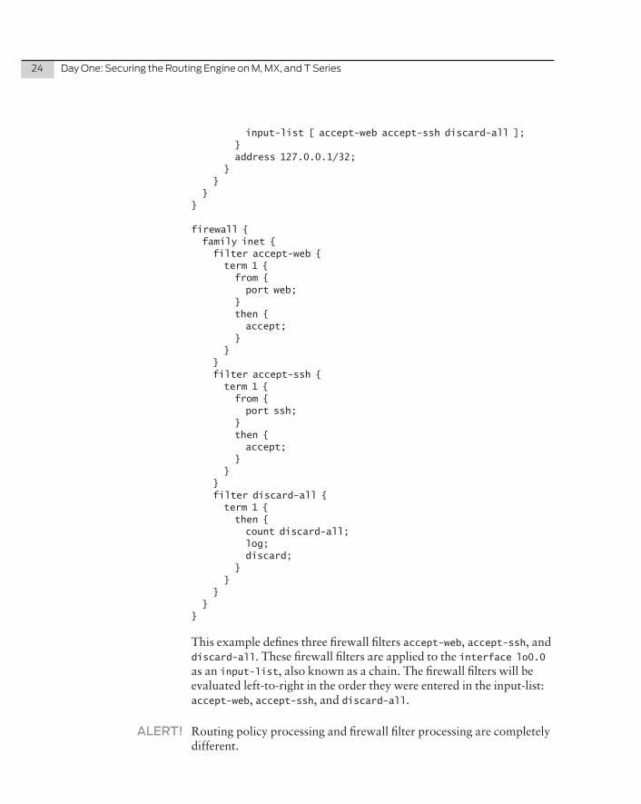
input-list [ accept-web accept-ssh discard-all ]; } address 127.0.0.1/32; } } }}
firewall { family inet { filter accept-web { term 1 { from { port web; } then { accept; } } } filter accept-ssh { term 1 { from { port ssh; } then { accept; } } } filter discard-all { term 1 { then { count discard-all; log; discard; } } } }}
This example defines three firewall filters accept-web, accept-ssh, and discard-all. These firewall filters are applied to the interface lo0.0 as an input-list, also known as a chain. The firewall filters will be evaluated left-to-right in the order they were entered in the input-list: accept-web, accept-ssh, and discard-all.
ALERT! Routing policy processing and firewall filter processing are completely different.
Chapter1:FirewallFilters 25
An important distinction when comparing firewall filter and routing policy processing is when the processing stops. In a routing policy chain the processing doesn’t stop until a terminating action is met or a match isn’t found. In a firewall filter chain the processing stops immediately after a match, even if you omit a terminating action.
ALERT! A maximum of 16 firewall filters can be applied as an input-list or output-list.
No matter how complex the problem, it’s possible to break it down into simple buildings blocks that are able to be used elsewhere. Creat-ing modular, individual firewall filters provides the added benefit of reusing them elsewhere in the configuration, thus allowing the opera-tor to “do more with less” and not reinvent the wheel.
For a perfect example, take two completely different problems such as writing a firewall filter for BGP peering traffic to the Internet and writing a firewall filter to protect the routing engine. At a high level, the two tasks are not related, but once these items are broken down into simple buildings blocks, patterns and common tasks appear. Individually each filter would want to block ICMP fragments and eventually discard that traffic at the end of the policy, but by creating common firewall filters to specifically perform these tasks and chaining them together, they can work together.
TIP Common firewall filters should be focused enough to accomplish the immediate task at hand, but generic enough to work in any scenario. Then you have a collection of common firewall filters as a bag of building blocks, and each block can be built on top of others in different ways for different filtering goals. It’s like network masonry.
Nested Firewall Filters
It’s possible to create a filter that references another filter. The only limitation is that this can only be done once per term and doesn’t support recursive firewall filters. Consider the following example:
[edit firewall family inet]filter accept-web { term 1 { from { port web; } then { accept; }
26 DayOne:SecuringtheRoutingEngineonM,MX,andTSeries
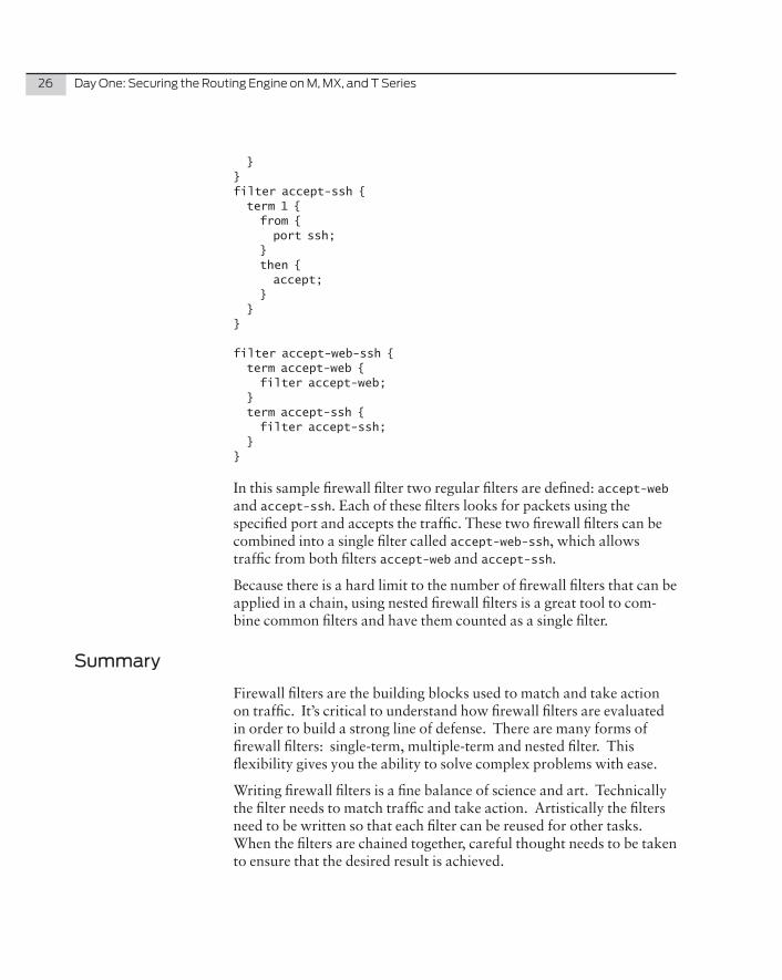
}}filter accept-ssh { term 1 { from { port ssh; } then { accept; } }}
filter accept-web-ssh { term accept-web { filter accept-web; } term accept-ssh { filter accept-ssh; }}
In this sample firewall filter two regular filters are defined: accept-web and accept-ssh. Each of these filters looks for packets using the specified port and accepts the traffic. These two firewall filters can be combined into a single filter called accept-web-ssh, which allows traffic from both filters accept-web and accept-ssh.
Because there is a hard limit to the number of firewall filters that can be applied in a chain, using nested firewall filters is a great tool to com-bine common filters and have them counted as a single filter.
Summary
Firewall filters are the building blocks used to match and take action on traffic. It’s critical to understand how firewall filters are evaluated in order to build a strong line of defense. There are many forms of firewall filters: single-term, multiple-term and nested filter. This flexibility gives you the ability to solve complex problems with ease.
Writing firewall filters is a fine balance of science and art. Technically the filter needs to match traffic and take action. Artistically the filters need to be written so that each filter can be reused for other tasks. When the filters are chained together, careful thought needs to be taken to ensure that the desired result is achieved.
Chapter 2
Policers
Policers Overview . . . . . . . . . . . . . . . . . . . . . . . . . . . . . . . . . . . . . . . . . . . . . . . .28
Token Bucket Algorithm . . . . . . . . . . . . . . . . . . . . . . . . . . . . . . . . . . . . . . . . . .28
Bandwidth-limit . . . . . . . . . . . . . . . . . . . . . . . . . . . . . . . . . . . . . . . . . . . . . . . . . 30
Burst-size-limit . . . . . . . . . . . . . . . . . . . . . . . . . . . . . . . . . . . . . . . . . . . . . . . . . . . 31
Rate-limiting Traffic . . . . . . . . . . . . . . . . . . . . . . . . . . . . . . . . . . . . . . . . . . . . . .32
Filter-specific Versus Term-specific . . . . . . . . . . . . . . . . . . . . . . . . . . . . . . .34
Summary . . . . . . . . . . . . . . . . . . . . . . . . . . . . . . . . . . . . . . . . . . . . . . . . . . . . . . . . 37
28 DayOne:SecuringtheRoutingEngineonM,MX,andTSeries
Chapter 2 explains what policers are and shows you how to use them. Rate limiting is performed via a firewall action that references a policer, and firewall filters and policers are used together to match traffic and enforce a rate limit. Let’s start.
Policers Overview
Policing is synonymous with rate limiting. Policers work together with firewall filters to set bandwidth restrictions on matched traffic and enforce consequences on traffic exceeding the bandwidth limitation defined by the policer.
Despite the constant confusion, policers are very simple to configure. There are three major components that need to be defined: policer name, if-exceeding parameters, and the action. The policer configura-tion syntax is as follows:
firewall { policer policer-name { filter-specific; if-exceeding { bandwidth-limit bps; bandwidth-percent number; burst-size-limit bytes; } then { policer-action; } }}
Token Bucket Algorithm
Junos policers use the token-bucket algorithm to enforce an average bandwidth limit over time, while allowing for bursts that exceed the bandwidth limit.
Packets arrive at the policer at the rate at which they were originally sent and the policer decision process is run for each ingress packet. There are three parameters that the policer uses to determine if the packet will be accepted: packet size, bandwidth-limit, and burst-size-limit. The policer simply subtracts the packet size from the current size
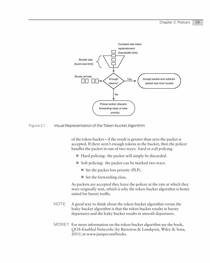
Chapter2:Policers 29
Enough tokens?
Policer-action (discard, forwarding-class or loss-
priority)
Accept packet and subtract packet size from bucket
Bursty arrivals
Constant-rate token replenishment(bandwidth-limit)
Bucket size(burst-size-limit)
No
Yes
Figure�2.1 VisualRepresentationoftheToken-bucketAlgorithm
of the token bucket – if the result is greater than zero the packet is accepted. If there aren’t enough tokens in the bucket, then the policer handles the packet in one of two ways: hard or soft policing.
�� Hard policing: the packet will simply be discarded.
�� Soft policing: the packet can be marked two ways.
�� Set the packet loss priority (PLP).
�� Set the forwarding class.
As packets are accepted they leave the policer at the rate at which they were originally sent, which is why the token-bucket algorithm is better suited for bursty traffic.
NOTE A good way to think about the token-bucket algorithm versus the leaky-bucket algorithm is that the token bucket results in bursty departures and the leaky bucket results in smooth departures.
MORE? For more information on the token-bucket algorithm see the book, QOS-Enabled Networks (by Barreiros & Lundqvist, Wiley & Sons, 2011) at www.juniper.net/books.
30 DayOne:SecuringtheRoutingEngineonM,MX,andTSeries
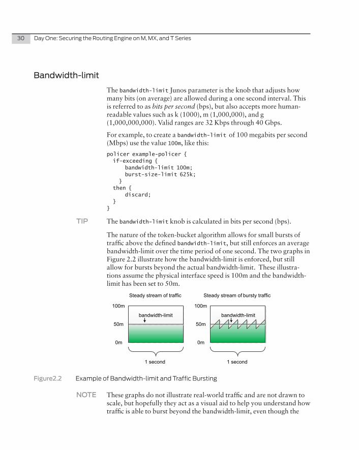
Bandwidth-limit
The bandwidth-limit Junos parameter is the knob that adjusts how many bits (on average) are allowed during a one second interval. This is referred to as bits per second (bps), but also accepts more human-readable values such as k (1000), m (1,000,000), and g (1,000,000,000). Valid ranges are 32 Kbps through 40 Gbps.
For example, to create a bandwidth-limit of 100 megabits per second (Mbps) use the value 100m, like this:
policer example-policer { if-exceeding { bandwidth-limit 100m; burst-size-limit 625k; } then { discard; }}
TIP The bandwidth-limit knob is calculated in bits per second (bps).
The nature of the token-bucket algorithm allows for small bursts of traffic above the defined bandwidth-limit, but still enforces an average bandwidth-limit over the time period of one second. The two graphs in Figure 2.2 illustrate how the bandwidth-limit is enforced, but still allow for bursts beyond the actual bandwidth-limit. These illustra-tions assume the physical interface speed is 100m and the bandwidth-limit has been set to 50m.
bandwidth-limit
1 second 1 second
Steady stream of traffic Steady stream of bursty traffic
100m
0m
50m
100m
0m
50m
bandwidth-limit
Figure2.2� ExampleofBandwidth-limitandTrafficBursting
NOTE These graphs do not illustrate real-world traffic and are not drawn to scale, but hopefully they act as a visual aid to help you understand how traffic is able to burst beyond the bandwidth-limit, even though the
Chapter2:Policers 31
average bandwidth over a period of 1 second is still equal to the bandwidth-limit.
In the first graph there is a steady stream of traffic using exactly 50Mbps. In this case the token bucket remains full because as traffic comes in, the bandwidth-limit replenishes tokens into the bucket at the exact same rate as the incoming traffic.
The second graph illustrates a steady stream of traffic around 40 Mbps; it has small bursts up to 60 Mbps, but then drops back down to 40 Mbps. The token bucket is nearly depleted after each burst, but the traffic drops back down to 40 Mbps to allow the tokens to fill up the bucket so there are enough tokens to burst again.
TIP The bandwidth-limit defines how fast the token bucket will be refilled every clock cycle. If the current traffic is below the bandwidth-limit, this means a surplus is created in the token bucket, whereas if the current traffic is above the bandwidth-limit, there is a deficit in the token bucket, until it’s depleted and begins policing traffic.
Burst-size-limit
The burst-size-limit defines how large the token bucket is. The token bucket controls the amount of burst permitted before packets are policed. Since the bandwidth-limit is a constant value used to enforce an average bandwidth over time, the only variable to adjust how much burst the policer will allow is burst-size-limit.
There are two common methods for calculating the burst-size-limit.
1. If the average packet size is known in advance, set the burst-size-limit to average packet size * 10. If the packet size is unknown, the only option is to set the burst-size-limit to the physical interface’s MTU * 10.
2. Set the burst-size-limit to the amount of data the physical interface can transmit within a 5ms window.
NOTE The author finds that setting the burst-size-limit to the amount of bandwidth the physical interface can transmit in 5ms is the best method.
Setting a smaller burst-size-limit for real-time traffic is recommend-ed, but setting the value too low could cause the token bucket to
32 DayOne:SecuringtheRoutingEngineonM,MX,andTSeries
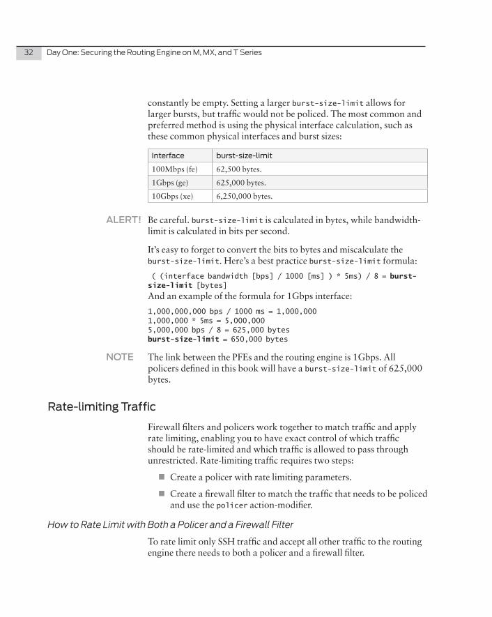
constantly be empty. Setting a larger burst -size-limit allows for larger bursts, but traffic would not be policed. The most common and preferred method is using the physical interface calculation, such as these common physical interfaces and burst sizes:
Interface burst-size-limit
100Mbps (fe) 62,500 bytes.
1Gbps (ge) 625,000 bytes.
10Gbps (xe) 6,250,000 bytes.
ALERT! Be careful. burst-size-limit is calculated in bytes, while bandwidth-limit is calculated in bits per second.
It’s easy to forget to convert the bits to bytes and miscalculate the burst-size-limit. Here’s a best practice burst-size-limit formula:
( (interface bandwidth [bps] / 1000 [ms] ) * 5ms) / 8 = burst-size-limit [bytes]
And an example of the formula for 1Gbps interface:
1,000,000,000 bps / 1000 ms = 1,000,0001,000,000 * 5ms = 5,000,0005,000,000 bps / 8 = 625,000 bytesburst-size-limit = 650,000 bytes
NOTE The link between the PFEs and the routing engine is 1Gbps. All policers defined in this book will have a burst-size-limit of 625,000 bytes.
Rate-limiting Traffic
Firewall filters and policers work together to match traffic and apply rate limiting, enabling you to have exact control of which traffic should be rate-limited and which traffic is allowed to pass through unrestricted. Rate-limiting traffic requires two steps:
�� Create a policer with rate limiting parameters.
�� Create a firewall filter to match the traffic that needs to be policed and use the policer action-modifier.
How to Rate Limit with Both a Policer and a Firewall Filter
To rate limit only SSH traffic and accept all other traffic to the routing engine there needs to both a policer and a firewall filter.
Chapter2:Policers 33
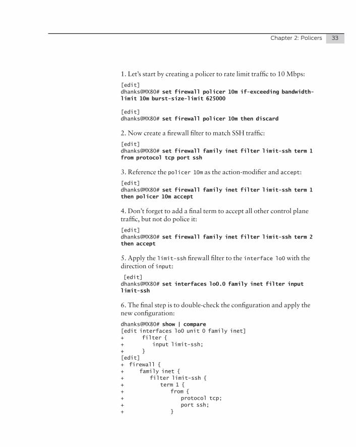
1. Let’s start by creating a policer to rate limit traffic to 10 Mbps:
[edit]dhanks@MX80# set firewall policer 10m if-exceeding bandwidth-limit 10m burst-size-limit 625000
[edit]dhanks@MX80# set firewall policer 10m then discard
2. Now create a firewall filter to match SSH traffic:
[edit]dhanks@MX80# set firewall family inet filter limit-ssh term 1 from protocol tcp port ssh
3. Reference the policer 10m as the action-modifier and accept:
[edit]dhanks@MX80# set firewall family inet filter limit-ssh term 1 then policer 10m accept
4. Don’t forget to add a final term to accept all other control plane traffic, but not do police it:
[edit]dhanks@MX80# set firewall family inet filter limit-ssh term 2 then accept
5. Apply the limit-ssh firewall filter to the interface lo0 with the direction of input:
[edit]dhanks@MX80# set interfaces lo0.0 family inet filter input limit-ssh
6. The final step is to double-check the configuration and apply the new configuration:
dhanks@MX80# show | compare [edit interfaces lo0 unit 0 family inet]+ filter {+ input limit-ssh;+ }[edit]+ firewall {+ family inet {+ filter limit-ssh {+ term 1 {+ from {+ protocol tcp;+ port ssh;+ }
34 DayOne:SecuringtheRoutingEngineonM,MX,andTSeries
+ then {+ policer 10m;+ accept;+ }+ }+ term 2 {+ then accept;+ }+ }+ }+ policer 10m {+ if-exceeding {+ bandwidth-limit 10m;+ burst-size-limit 625k;+ }+ then discard;+ }+ }
[edit]dhanks@MX80# commit and-quit commit completeExiting configuration mode
dhanks@MX80>
The first term in the filter specifically matches SSH traffic by looking at the port and protocol. If a match is found, it will police SSH traffic using the policer 10m. The second term is there to override the implicit discard all at the end of the policer. The simple firewall filter and policer illustrate how it’s possible to only police SSH traffic while allowing all other traffic to the routing engine.
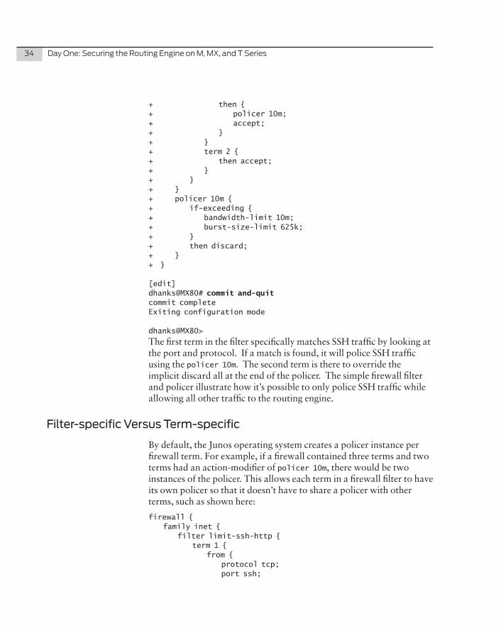
Filter-specific Versus Term-specific
By default, the Junos operating system creates a policer instance per firewall term. For example, if a firewall contained three terms and two terms had an action-modifier of policer 10m, there would be two instances of the policer. This allows each term in a firewall filter to have its own policer so that it doesn’t have to share a policer with other terms, such as shown here:
firewall { family inet { filter limit-ssh-http { term 1 { from { protocol tcp; port ssh;
Chapter2:Policers 35
} then { policer 10m; accept; } } term 2 { from { protocol tcp; port http; } then { policer 10m; accept; } } term 3 { then accept; } } } policer 10m { if-exceeding { bandwidth-limit 10m; burst-size-limit 625k; } then discard; }}
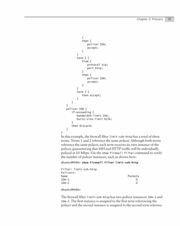
In this example, the firewall filter limit-ssh-http has a total of three terms. Terms 1 and 2 reference the same policer. Although both terms reference the same policer, each term receives its own instance of the policer, guaranteeing that SSH and HTTP traffic will be individually policed at 10 Mbps. Use the show firewall filter command to verify the number of policer instances, such as shown here:
dhanks@MX80> show firewall filter limit-ssh-http
Filter: limit-ssh-http Policers:Name Packets 10m-1 010m-2 0
dhanks@MX80>
The firewall filter limit-ssh-http has two policer instances: 10m-1 and 10m-2. The first instance is assigned to the first term referencing the policer and the second instance is assigned to the second term referenc-
36 DayOne:SecuringtheRoutingEngineonM,MX,andTSeries
ing the policer.
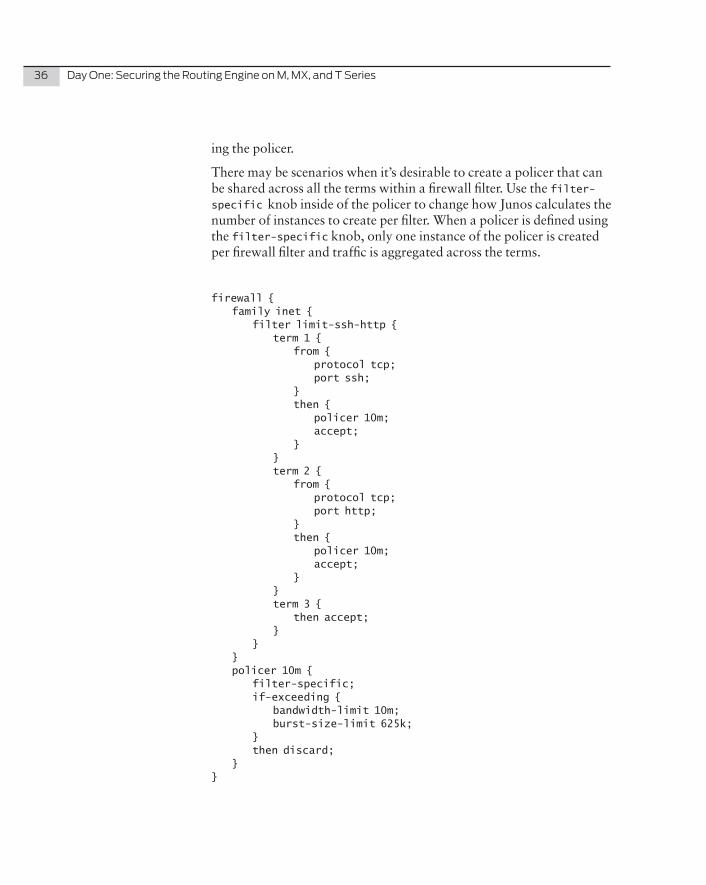
There may be scenarios when it’s desirable to create a policer that can be shared across all the terms within a firewall filter. Use the filter-specific knob inside of the policer to change how Junos calculates the number of instances to create per filter. When a policer is defined using the filter-specific knob, only one instance of the policer is created per firewall filter and traffic is aggregated across the terms.
firewall { family inet { filter limit-ssh-http { term 1 { from { protocol tcp; port ssh; } then { policer 10m; accept; } } term 2 { from { protocol tcp; port http; } then { policer 10m; accept; } } term 3 { then accept; } } } policer 10m { filter-specific; if-exceeding { bandwidth-limit 10m; burst-size-limit 625k; } then discard; }}
Chapter2:Policers 37
Here, the firewall filter limit-ssh-http has three terms, two of which have an action-modifier of policer 10m. The difference is that the policer 10m now has the knob filter-specific, so there is only one policer instance created for the firewall filter limit-ssh-http:
dhanks@MX80> show firewall filter limit-ssh-http
Filter: limit-ssh-http Policers:Name Packets 10m 0
dhanks@MX80>
The firewall filter limit-ssh-http now only has a single policer instance. Both SSH and HTTP traffic will be policed to 10 Mbps as a whole.
Summary
Historically, policing has been one of the more difficult topics to under-stand in depth. Stepping back from all of the implementation details and focusing on the actual token bucket algorithm helps you to understand how policing actually works. The bandwidth limit and token bucket size work together to enforce how much traffic is allowed during a one second interval.
If traffic exceeds the limits defined by the policer, the traffic is either soft policed or hard policed. Soft policing traffic allows you to set the PLP or forwarding class of the packet. Hard policing will silently discard the traffic.
Policers come in two flavors: term-specific and filter-specific. By default policers are term-specific. A term-specific policer will have an instance created for every term in a firewall filter for which it’s applied. On the other hand, if a policer is filter-specific, regardless of the number of terms to which the policer is applied, only a single instance of the policer is created.

38 DayOne:SecuringtheRoutingEngineonM,MX,andTSeries
Chapter 3
Viewing Counters, Logs, and Policers
Viewing Firewall Filter Counters . . . . . . . . . . . . . . . . . . . . . . . . . . . . . . . . . . 40
Viewing the Firewall Filter Log . . . . . . . . . . . . . . . . . . . . . . . . . . . . . . . . . . . . .45
Viewing Firewall Policers . . . . . . . . . . . . . . . . . . . . . . . . . . . . . . . . . . . . . . . . . 47
Summary . . . . . . . . . . . . . . . . . . . . . . . . . . . . . . . . . . . . . . . . . . . . . . . . . . . . . . . 48
40 DayOne:SecuringtheRoutingEngineonM,MX,andTSeries
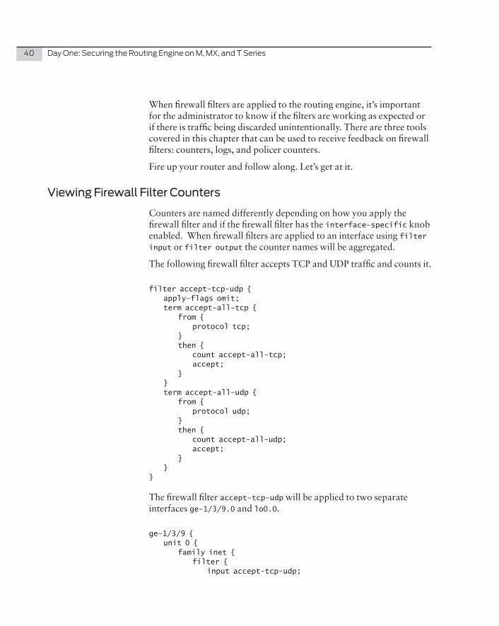
When firewall filters are applied to the routing engine, it’s important for the administrator to know if the filters are working as expected or if there is traffic being discarded unintentionally. There are three tools covered in this chapter that can be used to receive feedback on firewall filters: counters, logs, and policer counters.
Fire up your router and follow along. Let’s get at it.
Viewing Firewall Filter Counters
Counters are named differently depending on how you apply the firewall filter and if the firewall filter has the interface-specific knob enabled. When firewall filters are applied to an interface using filter input or filter output the counter names will be aggregated.
The following firewall filter accepts TCP and UDP traffic and counts it.
filter accept-tcp-udp { apply-flags omit; term accept-all-tcp { from { protocol tcp; } then { count accept-all-tcp; accept; } } term accept-all-udp { from { protocol udp; } then { count accept-all-udp; accept; } }}
The firewall filter accept-tcp-udp will be applied to two separate interfaces ge-1/3/9.0 and lo0.0.
ge-1/3/9 { unit 0 { family inet { filter { input accept-tcp-udp;
Chapter3:ViewingCounters,Logs,andPolicers 41
} address 1.1.1.1/30; } }}lo0 { unit 0 { family inet { filter { input accept-tcp-udp; } address 172.16.2.1/32; } }}
Notice although the firewall filter is applied to two separate interfaces, there is only a single instance of the counter.
dhanks@MX80> show firewall filter accept-tcp-udp
Filter: accept-tcp-udp Counters:Name Bytes Packetsaccept-all-tcp 222752 3777accept-all-udp 1088 14
dhanks@MX80>
There are two ways to change this behavior. Enabling the interface-specific knob on the firewall filter accept-tcp-udp or applying the filter using a filter input-list.
interface-specific
Let’s take a look at the interface-specific knob and how it changes the behavior.
dhanks@MX80> configure Entering configuration mode
dhanks@MX80# set firewall family inet filter accept-tcp-udp interface-specific
[edit]dhanks@MX80# commit and-quit commit completeExiting configuration mode
dhanks@MX80> show firewall filter accept-tcp-udp-lo0.0-i
42 DayOne:SecuringtheRoutingEngineonM,MX,andTSeries
Filter: accept-tcp-udp-lo0.0-i Counters:Name Bytes Packetsaccept-all-tcp-lo0.0-i 12736 243accept-all-udp-lo0.0-i 0 0
dhanks@MX80> show firewall filter accept-tcp-udp-ge-1/3/9.0-i
Filter: accept-tcp-udp-ge-1/3/9.0-i Counters:Name Bytes Packetsaccept-all-tcp-ge-1/3/9.0-i 0 0accept-all-udp-ge-1/3/9.0-i 0 0
dhanks@MX80>
Notice how the counters are named differently. The counter naming convention when using the interface-specific knob is <counter_name>-<interface>.<unit>-<direction>. Also note that the firewall filter name has changed as well.
Firewall Chaining
Now let’s try applying the firewall filter as a chain.
dhanks@MX80> configure Entering configuration mode
[edit]dhanks@MX80# delete interfaces lo0.0 family inet filter
[edit]dhanks@MX80# set interfaces lo0.0 family inet filter input-list accept-tcp-udp
[edit]dhanks@MX80# delete interfaces ge-1/3/9.0 family inet filter
[edit]dhanks@MX80# set interfaces ge-1/3/9.0 family inet filter input-list accept-tcp-udp
[edit]dhanks@MX80# commit and-quit commit completeExiting configuration modedhanks@MX80> show firewall filter lo0.0-i
Filter: lo0.0-i Counters:Name Bytes Packetsaccept-all-tcp-lo0.0-i 8600 150accept-all-udp-lo0.0-i 0 0
Chapter3:ViewingCounters,Logs,andPolicers 43
dhanks@MX80> show firewall filter ge-1/3/9.0-i
Filter: ge-1/3/9.0-i Counters:Name Bytes Packetsaccept-all-tcp-ge-1/3/9.0-i 0 0accept-all-udp-ge-1/3/9.0-i 0 0
dhanks@MX80>
Notice that when using firewall chaining, the counter names are identical, but the firewall filter name is different than using the inter-face-specific method. The filter naming convention for firewall chaining is <interface>.<unit>-<direction>.
Table�3.1 FilterNamingConvention
Method Counter Naming Convention Filter Naming Convention
Default Counter Name Filter Name
interface-specific <counter_name>-<interface>.<unit>-<direction>
<filter_name>-<interface>.<unit>-<direction>
Firewall Chaining <counter_name>-<interface>.<unit>-<direction>
<interface>.<unit>-<direction>
It’s recommended that firewall filters be applied as a chain. The counter and firewall filter names are easy to read and remember. The data is also broken out per interface so that there is more information available during troubleshooting and analysis.
Naming Convention
It’s recommended that you have a naming convention when creating firewall filters, terms, and counters. For purposes of this book, the convention is to keep the term and counter name the same when creating filters.
Let’s take a look at a firewall filter that has multiple terms and you can see how it varies from a firewall filter with a single term. In the next filter example, the firewall filter accept-icmp has two terms: no-icmp-fragments and accept-icmp. According to the convention of this book, each term has a counter with the same name as the term:
firewall { family inet {
44 DayOne:SecuringtheRoutingEngineonM,MX,andTSeries
filter accept-icmp { term no-icmp-fragments { from { is-fragment; protocol icmp; } then { count no-icmp-fragments; log; discard; } } term accept-icmp { from { protocol icmp; icmp-type [ echo-reply echo-request time-exceeded unreachable source-quench router-advertisement parameter-problem ]; } then { policer management-5m; º accept; } } } }}
You can see that multiple term firewall filters follow the same logic as single term firewall filters, and you can use the show firewall counter command using the filter name and counter name as arguments:
dhanks@MX80> show firewall counter no-icmp-fragments-lo0.0-i filter lo0.0-i
Filter: lo0.0-i Counters:Name Bytes Packetsno-icmp-fragments-lo0.0-i 13824 12
dhanks@MX80> show firewall counter accept-icmp-lo0.0-i filter lo0.0-i
Filter: lo0.0-i Counters:Name Bytes Packetsaccept-icmp-lo0.0-i 20312 213
dhanks@MX80>
Keeping the counter names in sync with the firewall filter’s term names makes it easy to understand where the counter was applied.
Chapter3:ViewingCounters,Logs,andPolicers 45
Viewing the Firewall Filter Log
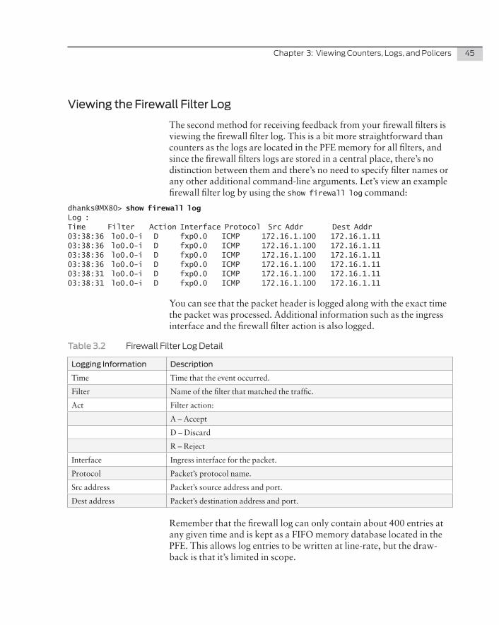
The second method for receiving feedback from your firewall filters is viewing the firewall filter log. This is a bit more straightforward than counters as the logs are located in the PFE memory for all filters, and since the firewall filters logs are stored in a central place, there’s no distinction between them and there’s no need to specify filter names or any other additional command-line arguments. Let’s view an example firewall filter log by using the show firewall log command:
dhanks@MX80> show firewall log Log :Time Filter Action Interface Protocol Src Addr Dest Addr03:38:36 lo0.0-i D fxp0.0 ICMP 172.16.1.100 172.16.1.1103:38:36 lo0.0-i D fxp0.0 ICMP 172.16.1.100 172.16.1.1103:38:36 lo0.0-i D fxp0.0 ICMP 172.16.1.100 172.16.1.1103:38:36 lo0.0-i D fxp0.0 ICMP 172.16.1.100 172.16.1.1103:38:31 lo0.0-i D fxp0.0 ICMP 172.16.1.100 172.16.1.1103:38:31 lo0.0-i D fxp0.0 ICMP 172.16.1.100 172.16.1.11
You can see that the packet header is logged along with the exact time the packet was processed. Additional information such as the ingress interface and the firewall filter action is also logged.
Table�3.2� FirewallFilterLogDetail
Logging Information Description
Time Time that the event occurred.
Filter Name of the filter that matched the traffic.
Act Filter action:
A – Accept
D – Discard
R – Reject
Interface Ingress interface for the packet.
Protocol Packet’s protocol name.
Src address Packet’s source address and port.
Dest address Packet’s destination address and port.
Remember that the firewall log can only contain about 400 entries at any given time and is kept as a FIFO memory database located in the PFE. This allows log entries to be written at line-rate, but the draw-back is that it’s limited in scope.
46 DayOne:SecuringtheRoutingEngineonM,MX,andTSeries
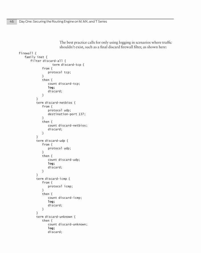
The best practice calls for only using logging in scenarios where traffic shouldn’t exist, such as a final discard firewall filter, as shown here:
firewall { family inet { filter discard-all { term discard-tcp { from { protocol tcp; } then { count discard-tcp; log; discard; } } term discard-netbios { from { protocol udp; destination-port 137; } then { count discard-netbios; discard; } } term discard-udp { from { protocol udp; } then { count discard-udp; log; discard; } } term discard-icmp { from { protocol icmp; } then { count discard-icmp; log; discard; } } term discard-unknown { then { count discard-unknown; log; discard;
Chapter3:ViewingCounters,Logs,andPolicers 47
} } } } }
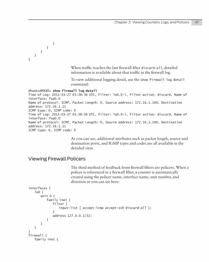
When traffic reaches the last firewall filter discard-all, detailed information is available about that traffic in the firewall log.
To view additional logging detail, use the show firewall log detail command:
dhanks@MX80> show firewall log detail Time of Log: 2011-03-27 03:38:36 UTC, Filter: lo0.0-i, Filter action: discard, Name of interface: fxp0.0Name of protocol: ICMP, Packet Length: 0, Source address: 172.16.1.100, Destination address: 172.16.1.11ICMP type: 0, ICMP code: 0Time of Log: 2011-03-27 03:38:36 UTC, Filter: lo0.0-i, Filter action: discard, Name of interface: fxp0.0Name of protocol: ICMP, Packet Length: 0, Source address: 172.16.1.100, Destination address: 172.16.1.11ICMP type: 0, ICMP code: 0
As you can see, additional attributes such as packet length, source and destination ports, and IGMP types and codes are all available in the detailed view.
Viewing Firewall Policers
The third method of feedback from firewall filters are policers. When a policer is referenced in a firewall filter, a counter is automatically created using the policer name, interface name, unit number, and direction as you can see here:
interfaces { lo0 { unit 0 { family inet { filter { input-list [ accept-icmp accept-ssh discard-all ]; } address 127.0.0.1/32; } } }}firewall { family inet {
48 DayOne:SecuringtheRoutingEngineonM,MX,andTSeries
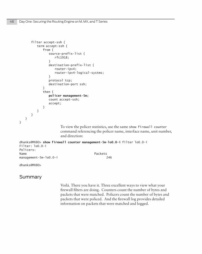
filter accept-ssh { term accept-ssh { from { source-prefix-list { rfc1918; } destination-prefix-list { router-ipv4; router-ipv4-logical-systms; } protocol tcp; destination-port ssh; } then { policer management-5m; count accept-ssh; accept; } } } }}
To view the policer statistics, use the same show firewall counter command referencing the policer name, interface name, unit number, and direction:
dhanks@MX80> show firewall counter management-5m-lo0.0-i filter lo0.0-iFilter: lo0.0-i Policers:Name Packets management-5m-lo0.0-i 246
dhanks@MX80>
Summary
Voilá. There you have it. Three excellent ways to view what your firewall filters are doing. Counters count the number of bytes and packets that were matched. Policers count the number of bytes and packets that were policed. And the firewall log provides detailed information on packets that were matched and logged.
Chapter 4
Junos Configuration Automation
Apply-path . . . . . . . . . . . . . . . . . . . . . . . . . . . . . . . . . . . . . . . . . . . . . . . . . . . . . . . 51
Apply-flags omit . . . . . . . . . . . . . . . . . . . . . . . . . . . . . . . . . . . . . . . . . . . . . . . . .54
Summary . . . . . . . . . . . . . . . . . . . . . . . . . . . . . . . . . . . . . . . . . . . . . . . . . . . . . . . . 57
50 DayOne:SecuringtheRoutingEngineonM,MX,andTSeries
Firewall filters and prefix lists are so tightly coupled that a single change can cause ripple effects throughout the entire configuration. As your configuration grows with new firewall filters and prefix lists, it poses ongoing operational challenges. Chapter 4 introduces you to Junos configuration automation, and is well worth the time it takes to review it.
BGP neighbor changes are a good example of complexity. If prefix lists are being used, the administrator must ensure that the BGP neighbor information is replicated into the prefix lists. If prefix lists aren’t being used, the administrator has to go through each firewall filter and make sure that the BGP neighbor information is included in the firewall filter’s from statement as shown below:
filter accept-bgp { term accept-bgp { from { source-address { 192.0.2.5; 192.0.2.6; 192.0.2.7; 192.0.2.8; 192.0.2.9; 192.0.2.10; 192.0.2.11; } destination-address { 10.255.255.5; 10.255.255.6; 10.255.255.7; 10.255.255.8; 10.255.255.9; } protocol tcp; port bgp; } then { count accept-bgp; accept; } }}
Several different tools are available to mitigate the complexity and number of touch points of your Junos configuration. For all the tools covered in this chapter, the general rule of thumb is to let Junos do all the repetitive work. You won’t find it in any data sheet but it’s one of the reasons you choose Junos in the first place, right?
Chapter4:JunosConfigurationAutomation 51
Apply-path
As your Junos configuration grows larger you’ll see a lot of redundant information such as IP addresses and prefix lists. To help fight against this redundant information clouding up your configuration, there’s a Junos feature called apply-path. Using keywords to match patterns inside of the Junos configuration, the apply-path feature applies the matched results into a dynamic prefix list.
The example below shows an IPv4 interface configuration and the corresponding static prefix list:
interfaces { ge-1/0/8 { unit 0 { family inet { address 10.0.8.6/30; } } } ge-1/0/9 { unit 0 { family inet { address 10.0.8.9/30; } } } ge-1/1/6 { unit 0 { family inet { address 10.0.2.1/30; } } } ge-1/1/7 { unit 0 { family inet { address 10.0.2.9/30; } } } }policy-options { prefix-list router-manual-ipv4 { 10.0.2.0/30; 10.0.2.8/30; 10.0.8.4/30; 10.0.8.8/30; }}
52 DayOne:SecuringtheRoutingEngineonM,MX,andTSeries
You can see that the IPv4 addresses are originally defined on the interfaces, but to build a prefix list that contains all of the IPv4 address-es, there is a lot of keying in of redundant information. Creating a prefix list and manually adding one address at a time is mundane. As your network grows and changes, these prefix lists need to be updated as well. Static configuration is a risk as it could lead to the prefix list update being overlooked during an interface change, which would cause downtime or additional work to debug and resolve the issue.
Using apply-path allows Junos to do the repetitive work and maintain an up-to-date prefix list. The feature works by matching keywords inside the configuration using wildcards, then applying the matching addresses to create a dynamic prefix list. Let’s try one:
prefix-list router-ipv4 { apply-path “interfaces <*> unit <*> family inet address <*>”;}
You can see in the prefix-list router-ipv4 example that Junos begins at the interfaces stanza and using the <*> wildcard matches all interfaces, then matches all unit numbers, then explicitly moves into family inet address and matches all IPv4 addresses again with the <*> wildcard.
To see how Junos applied the wildcards to build the dynamic prefix list, use the display inheritance command when viewing the configura-tion:
[edit]dhanks@MX80# show policy-options prefix-list router-ipv4 | display inheritance #### apply-path was expanded to:## 10.0.8.4/30; ## 10.0.8.8/30; ## 10.0.2.0/30; ## 10.0.2.8/30; ##apply-path “interfaces <*> unit <*> family inet address <*>”;
[edit]dhanks@MX80#
Now you can see that the prefix list router-ipv4 contains four entries that match all of the IPv4 addresses on the physical interfaces.
ALERT! It’s critical to understand that apply-path automatically fills out the prefix list using the Direct route instead of the Local route.
A Direct route in Junos is simply the logical interface’s network address
Chapter4:JunosConfigurationAutomation 53
plus the network mask. For example, if the logical interface’s IP address was family inet address 10.0.0.1/30 the network address would be 10.0.0.0 and the network mask would be 30 bits, resulting in a Direct route of 10.0.0.0/30.
A Local route in Junos is the logical interface’s IP address combined with a 32 bit mask. A good way to think of a Local route is as the actual IP address that resides on the router. For example if the logical interface IP address was family inet address 10.0.0.1/30 the Local route would be 10.0.0.1/32.
NOTE Using wildcards with apply-path is similar to the way that wildcards work with Junos configuration groups. For more information about Junos wildcards and configuration groups visit http://www.juniper.net/techpubs/en_US/junos10.4/topics/concept/junos-cli-wildcard-charac-ters-configuration-groups-usage.html
The last match in your apply-path statement must be an IP address. For example if the last match was not an IP address, Junos would instantly return with an error on the CLI:
dhanks@MX80# set policy-options prefix-list test apply-path “interfaces <*>” error: ‘interface_name’ is not IP address typeerror: invalid value: interfaces <*>
[edit]dhanks@MX80#
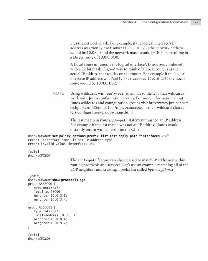
The apply-path feature can also be used to match IP addresses within routing protocols and services. Let’s use an example matching all of the BGP neighbors and creating a prefix list called bgp-neighbors:
[edit]dhanks@MX80# show protocols bgp group AS65000 { type external; local-as 65000; neighbor 10.0.3.3; neighbor 10.0.3.4;}group AS65001 { type internal; local-address 10.0.6.1; neighbor 10.0.9.6; neighbor 10.0.9.7;}
[edit]dhanks@MX80#
54 DayOne:SecuringtheRoutingEngineonM,MX,andTSeries
You can see that there are two BGP groups with two neighbors each, making a total of four BGP neighbors.
[edit]dhanks0@MX80# show policy-options prefix-list bgp-neighbors | display inheritance #### apply-path was expanded to:## 10.0.3.3/32; ## 10.0.3.4/32; ## 10.0.9.6/32; ## 10.0.9.7/32; ##apply-path “protocols bgp group <*> neighbor <*>”;
[edit]dhanks@MX80#
In this scenario, the apply-path begins at the protocols bgp stanza and matches all groups and all neighbors using the <*> wildcard. The last match catches the IP address and automatically fills out the prefix list bgp-neighbors.
ALERT!� Using apply-path doesn’t protect a prefix list against misconfiguration. If you add a bad BGP neighbor address the apply-path will automati-cally update the prefix list and allow the traffic to be passed though the firewall filter.
Apply-flags omit
Another method of reducing the Junos visual configuration is a hidden flag called omit. This option removes all child configuration from view and replaces it with /* OMITTED */. The omit keyword is useful for hiding large amounts of information that you won’t use on a daily basis. Let’s use an example by examining the details of the firewall filter discard-all:
dhanks@MX80# show firewall family inet filter discard-all term discard-tcp { from { protocol tcp; } then { count discard-tcp; log; discard; }}term discard-netbios {
Chapter4:JunosConfigurationAutomation 55
from { protocol udp; destination-port 137; } then { count discard-netbios; discard; }}term discard-udp { from { protocol udp; } then { count discard-udp; log; discard; }}term discard-icmp { from { protocol icmp; } then { count discard-icmp; log; discard; }}term discard-unknown { then { count discard-unknown; log; discard; }}
[edit]dhanks@MX80#
This single firewall filter is nearly fifty lines in length and is generic enough that it is not going to be changed on a regular basis. It’s a perfect candidate for being omitted while viewing your configuration using the apply-flags command:
[edit]dhanks@MX80# set firewall family inet filter discard-all apply-flags omit
[edit]dhanks@MX80#
56 DayOne:SecuringtheRoutingEngineonM,MX,andTSeries
Now, when your configuration is viewed with the show command, it is omitted:
family inet { filter discard-all { /* OMITTED */ }; [edit]dhanks@MX80#
NOTE Because omit is a hidden command, you can’t use tab-completion when configuring apply-flags. You need to type it out completely. It also will not show up in the inline help menu when you press ?.
NOTE Configuration sections with the apply-flags omit are omitted only when viewed at a higher level. For example typing show firewall family inet filter discard-all would show the entire filter, whereas typing show firewall family inet shows it as being omitted.
Using the apply-flags omit has reduced this firewall filter from nearly fifty lines to a single line. But you should know that when you are viewing omitted configuration at a higher level, it’s possible to still view the entire configuration using the command-line option display omit, as here:
[edit]dhanks@MX80# show firewall family inet | display omit filter discard-all { apply-flags omit; term discard-tcp { from { protocol tcp; } then { count discard-tcp; log; discard; } } term discard-netbios { from { protocol udp; destination-port 137; } then { count discard-netbios; discard; }
Chapter4:JunosConfigurationAutomation 57
} term discard-udp { from { protocol udp; } then { count discard-udp; log; discard; } } term discard-icmp { from { protocol icmp; } then { count discard-icmp; log; discard; } } term discard-unknown { then { count discard-unknown; log; discard; } }}
Summary
The apply-path feature creates and maintains a prefix list based on the Junos configuration. The omit feature is verbose when you want it and terse when you need it. These simple tools pay big dividends. Let Junos work for you, not the other way around. Junos was designed to easily handle scale without creating operational burdens.

58 DayOne:SecuringtheRoutingEngineonM,MX,andTSeries
Chapter 5
Creating a Basic Framework of Firewall Filters
Overview of a Firewall Filter Framework . . . . . . . . . . . . . . . . . . . . . . . . . . 60
Prefix Lists . . . . . . . . . . . . . . . . . . . . . . . . . . . . . . . . . . . . . . . . . . . . . . . . . . . . . . . 61
Policers . . . . . . . . . . . . . . . . . . . . . . . . . . . . . . . . . . . . . . . . . . . . . . . . . . . . . . . . . 69
Firewall Filters . . . . . . . . . . . . . . . . . . . . . . . . . . . . . . . . . . . . . . . . . . . . . . . . . . . . 72
Summary . . . . . . . . . . . . . . . . . . . . . . . . . . . . . . . . . . . . . . . . . . . . . . . . . . . . . . . 98
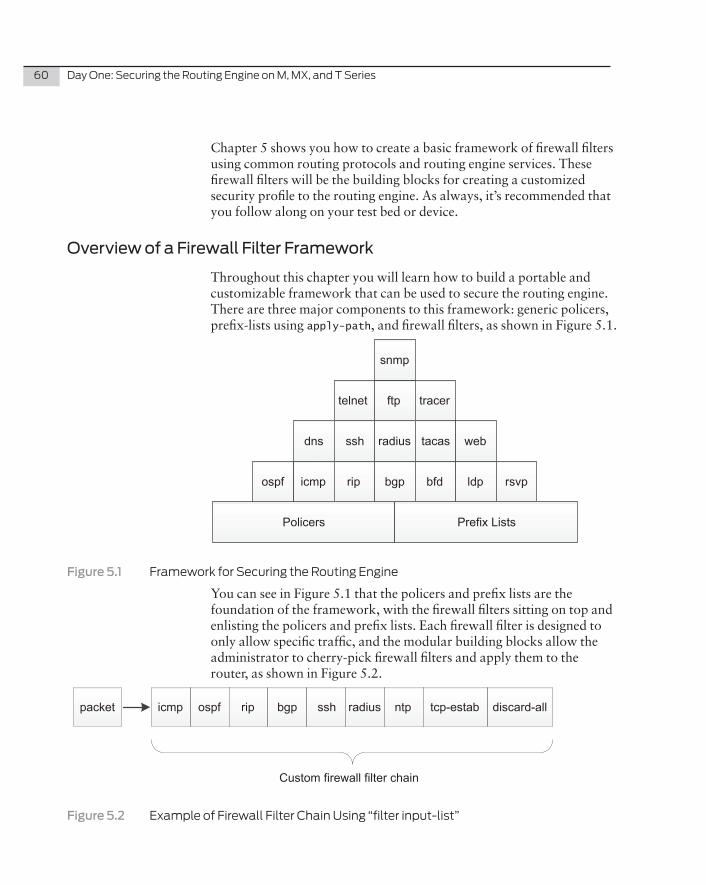
60 DayOne:SecuringtheRoutingEngineonM,MX,andTSeries
Chapter 5 shows you how to create a basic framework of firewall filters using common routing protocols and routing engine services. These firewall filters will be the building blocks for creating a customized security profile to the routing engine. As always, it’s recommended that you follow along on your test bed or device.
Overview of a Firewall Filter Framework
Throughout this chapter you will learn how to build a portable and customizable framework that can be used to secure the routing engine. There are three major components to this framework: generic policers, prefix-lists using apply-path, and firewall filters, as shown in Figure 5.1.
dns ssh radius tacas web
Policers Prefix Lists
icmp rip bgp bfd ldp rsvp
telnet ftp tracer
snmp
ospf
Figure�5.1� FrameworkforSecuringtheRoutingEngine
You can see in Figure 5.1 that the policers and prefix lists are the foundation of the framework, with the firewall filters sitting on top and enlisting the policers and prefix lists. Each firewall filter is designed to only allow specific traffic, and the modular building blocks allow the administrator to cherry-pick firewall filters and apply them to the router, as shown in Figure 5.2.
ospficmp rip bgp ssh radius ntp tcp-estabpacket
Custom firewall filter chain
discard-all
Figure�5.2� ExampleofFirewallFilterChainUsing“filterinput-list”
Chapter5:CreatingaBasicFrameworkofFirewallFilters 61
The overall goal of this framework is that it should be portable enough to move into the majority of environments and “just work” without major modification. The prefix lists should be generic enough to include basic services, protocols, and the router’s IPv4 addresses. The firewall filters should be written so that each filter focuses on a specific problem, and when the prefix lists are built using apply-path, modifi-cation shouldn’t be necessary.
The firewall filters should be designed to be used on the control plane using the interface lo0.0 in the direction of input. The firewall filters are modular, so they’re able to be applied with the input-list option and be chained together to create custom firewall requirements for your particular router.
In short, this framework applies what was shown in the previous chapters of this book. You get modularity and customization at the same time, utilizing a single Junos operating system.
NOTE This chapter reviews and comments on a subset of the final framework configuration. The appendix contains the final working configuration in its entirety.
TIP A special Copy and Paste edition of this book can be downloaded from this book’s page at www.juniper.net/dayone. Its rich-text format allows you to copy and paste firewall filter configurations for your own use.
Prefix Lists
Prefix lists should use apply-path liberally when dealing with services, routing protocols, and router addresses, so that Junos is doing all of the redundant work and you can focus on more important things. The prefix lists can be referenced by the firewall filters without any modifi-cation as your network grows and changes
Local Addresses
Let’s start by creating prefix lists that define local addresses on the router. Depending on what type of hardware you are dealing with, there are different types of virtualization capabilities, so let’s use prefix lists that use IPv4 addresses defined on the router itself and inside of logical-systems.
62 DayOne:SecuringtheRoutingEngineonM,MX,andTSeries
RouterIPv4Addresses
Our prefix list router-ipv4 contains all of the IPv4 addresses on the physical router, and the prefix list router-ipv4-logical-systems contains all of the IPv4 addresses that exist within any logical-system:
prefix-list router-ipv4 { apply-path “interfaces <*> unit <*> family inet address <*>”;}prefix-list router-ipv4-logical-systms { apply-path “logical-systems <*> interfaces <*> unit <*> family inet address <*>”;}
NOTE The prefix-list router-ipv4 is aggressive and will contain every single IPv4 address on the physical router, including GRE tunnels, loopback interfaces, and routing engine management interfaces such as fxp0.
Localhost
The loopback is usually defined as 127.0.0.1/32 in Junos, but the RFC 1700 defines it as 127/8. Let’s create a prefix list called localhost that matches 127/8:
prefix-list localhost { 127.0.0.0/8;}
Protocols
Let’s take the most common routing protocols and their multicast addresses and create easy to read prefix lists, so the configuration is a little more human-readable.
OSPF
OSPF uses two well-known multicast addresses to establish adjacency and send Hello packets:
IPv4 Multicast Address Description
224.0.0.5 OSPF AllSPFRouters
224.0.0.6 OSPF AllDRouters
Let’s create the prefix-list ospf to match both of these well-known multicast addresses:
prefix-list ospf { 224.0.0.5/32; 224.0.0.6/32;}
Chapter5:CreatingaBasicFrameworkofFirewallFilters 63
RIP
RIPv2 uses a single well-known multicast address to exchange routing information, so let’s create the prefix list rip to match this well-known multicast address:
prefix-list rip { 224.0.0.9/32;}
VRRP
Virtual Router Redundancy Protocol (VRRP) uses a single well-known multicast address that physical routers use to communicate, and our prefix list vrrp matches the multicast address 224.0.0.18:
prefix-list vrrp { 224.0.0.18/32;}
MulticastAllRouters
The IPv4 multicast address 224.0.0.2 is reserved for AllRouters within a network segment. Protocols such as the Label Distribution Protocol (LDP) use this address to discover Hello packets. So let’s create a prefix list called multicast-all-routers to match this well-known multicast address:
prefix-list multicast-all-routers { 224.0.0.2/32;}
BGPNeighbors
Let’s use the apply-path feature to walk through the Junos configura-tion to discover all the BGP neighbors within the configuration.
prefix-list bgp-neighbors { apply-path “protocols bgp group <*> neighbor <*>”;}prefix-list bgp-neighbors-logical-systems { apply-path “logical-systems <*> protocols bgp group <*> neighbor <*>”;}
Services
The four most common services on a router are RADIUS, TACAS+, NTP, and SNMP. Let’s build prefix lists to match the appropriate sections of the Junos configuration and find the server IP addresses.
64 DayOne:SecuringtheRoutingEngineonM,MX,andTSeries
RADIUS
Junos allows for multiple RADIUS servers to be defined under the system radius-server stanza. Let’s create a prefix list to match all of the RADIUS servers:
system { radius-server { 192.168.0.10 secret “$9$whYaZ”; ## SECRET-DATA 192.168.0.11 secret “$9$5Q69”; ## SECRET-DATA 192.168.0.12 secret “$9$DMimf”; ## SECRET-DATA 192.168.0.13 secret “$9$ItYEre”; ## SECRET-DATA }}
Even though the IP address is located in between radius-server and secret, you can still use wildcards to match the IP addresses. Let’s create an apply-path that matches everything to the IP address and then stops, leaving out the secret:
prefix-list radius-servers { apply-path “system radius-server <*>”;}
This wildcard should match the four IP addresses 192.168.0.10 – 13, but’s let’s double-check that the apply-path is working as expected, by using the display inheritance command:
[edit]dhanks@MX80# show policy-options prefix-list radius-servers | display inheritance #### apply-path was expanded to:## 192.168.0.10; ## 192.168.0.11; ## 192.168.0.12; ## 192.168.0.13; ##apply-path “system radius-server <*>”;
[edit]dhanks@MX80#
The double hash marks (##) verify that Junos was able to match the IP addresses and expand them out in a list.
TACAS+
TACAS+ is very similar to RADIUS in its configuration. Junos supports multiple TACAS+ servers defined in the system tacplus-servers stanza, as you can see here:
Chapter5:CreatingaBasicFrameworkofFirewallFilters 65
system { tacplus-server { 172.16.0.100; 172.16.0.101; 172.16.0.102; 172.16.0.103; }}
Let’s leverage the apply-path from the prefix list radius-servers and build a similar prefix list for TACAS+:
prefix-list tacas-servers { apply-path “system tacplus-server <*>”;}
Once again it should work, but let’s verify the apply-path using the display inheritance command:
[edit]dhanks@MX80 # show policy-options prefix-list tacas-servers | display inheritance #### apply-path was expanded to:## 172.16.0.100/32; ## 172.16.0.101/32; ## 172.16.0.102/32; ## 172.16.0.103/32; ##apply-path “system tacplus-server <*>”;
[edit]dhanks@MX80#
You can see the four TACAS+ servers 172.16.0.100-103 and the double hashes to verify that the apply-path is working as expected.
NTP
The Network Time Protocol (NTP) is defined under the system ntp stanza, and Junos supports multiple NTP servers:
system { ntp { server 192.168.33.10; server 192.168.33.11; server 192.168.33.12; server 192.168.33.13; }}
66 DayOne:SecuringtheRoutingEngineonM,MX,andTSeries
Leveraging our experience with the previous apply-path prefix lists, let’s apply the same methodology to NTP.
prefix-list ntp-servers { apply-path “system ntp server <*>”;}
And verify with display inheritance:
prefix-list ntp-server { ## ## apply-path was expanded to: ## 192.168.33.10; ## 192.168.33.11; ## 192.168.33.12; ## 192.168.33.13; ## apply-path “system ntp server <*>”;}
Here apply-path was able to successfully match the NTP servers and find the four IP addresses 192.168.33.10-13.
Junos also allows the use of NTP peers, so let’s match those as well:
prefix-list ntp-server-peers { apply-path “system ntp peer <*>”;}
The greatest benefit to using apply-path is that Junos builds and maintains the dynamic prefix lists for you. As you add additional NTP servers to the configuration, there’s no need to go back and modify the prefix list ntp because Junos does this automatically.
SNMP
The Simple Network Management Protocol (SNMP) supports multiple communities and the ability to define a different set of clients that are able to access each community. Junos enables the use of the client-lists keyword, which is similar to prefix lists.
ALERT! SNMP client-list and prefix lists cannot share the same name.
Example SNMP configuration:
snmp { client-list internal { 10.0.0.0/8; 192.168.0.0/16;
Chapter5:CreatingaBasicFrameworkofFirewallFilters 67
172.16.0.0/12; } community public { authorization read-only; clients { 172.16.100.0/24; } } community private { authorization read-write; client-list-name internal; }}
SNMP provides you with multiple levels of configuration and flexibil-ity when defining which clients are allowed to access communities. Junos supports SNMP client-list, which acts as a prefix-list that can be applied to multiple SNMP communities.
To capture all of the SNMP clients, you need to define two prefix lists using apply-path. The first prefix list captures the statically defined clients and the other prefix list captures the SNMP client-lists.
prefix-list snmp-client-lists { apply-path “snmp client-list <*> <*>”;}prefix-list snmp-community-clients { apply-path “snmp community <*> clients <*>”;}
Best practice is to always verify:
[edit]dhanks@MX80# show policy-options prefix-list snmp-client-lists | display inheritance #### apply-path was expanded to:## 10.0.0.0/8; ## 192.168.0.0/16; ## 172.16.0.0/12; ## 203.0.113.15/32; ## 203.0.113.16/32; ## 198.51.100.55/32; ## 198.51.100.56/32; ##apply-path “snmp client-list <*> <*>”;
[edit]dhanks@MX80# show policy-options prefix-list snmp-community-clients | display inheritance ##
68 DayOne:SecuringtheRoutingEngineonM,MX,andTSeries
## apply-path was expanded to:## 172.16.100.0/24; ## 192.168.100.0/24; ##apply-path “snmp community <*> clients <*>”;
[edit]dhanks@MX80#
You can see here that the prefix list snmp-client-lists successfully aggregated together all of the clients defined in the SNMP client-lists. The last prefix list snmp-community-clients aggregated all of the statically defined clients under each SNMP community. By using these two prefix lists together you’re able to match any type of client combi-nation within SNMP.
DNS
Junos allows for multiple DNS name servers to be defined under system name-server:
system { name-server { 172.16.5.40; 172.16.5.41; 172.16.5.42; 172.16.5.43; }}
Let’s create a prefix list to match the name servers defined:
prefix-list dns-servers { apply-path “system name-server <*>”;}
And when verified:
[edit]dhanks@MX80# show policy-options prefix-list dns-servers | display inheritance #### apply-path was expanded to:## 172.16.5.40/32; ## 172.16.5.41/32; ## 172.16.5.42/32; ## 172.16.5.43/32; ##apply-path “system name-server <*>”;
[edit]dhanks@MX80#
Chapter5:CreatingaBasicFrameworkofFirewallFilters 69
Policers
Policing traffic on the routing engine is straightforward: define a bandwidth-limit and make the policer action discard any packets that exceed the bandwidth-limit. The burst-size-limit is the same across any policers applied to the routing engine because the link to the routing engine is 1Gbps, and the amount of bandwidth a 1 Gbps interface is able to send in 5ms is 625,000 bytes, which is the recommended value for the burst-size-limit.
Management
Let’s create two generic management policers. These policers are term-specific so that a policer instance is created for each firewall filter term, and the policer actions will be to discard any packets that exceed the bandwidth limit.
The benefit of using two generic policers is that it reduces the size of the configuration and makes the configuration less complex, while still maintaining the firewall filter term policing. The alternative to using a generic policer is to define a policer per firewall filter or term. The benefit to using a term-specific policer is that when viewing the policer with the show firewall command, there’s a policer instance for each firewall filter term. For example, if traffic for both SSH and SNMP had to be policed, it is possible to see how many packets of each were policed on a per firewall filter basis.
Previously it was recommended that firewall filter terms match the filter name and counter if possible. The value in such a naming conven-tion now becomes apparent when trying to understand how many packets were policed for a particular firewall filter. Using this method allows you to create generic policers, but to apply them to specific firewall filters and maintain full visibility into policing statistics.
It’s easily illustrated by viewing the output of show firewall and comparing the output between term-specific and filter-specific policers.
Term-specific (default)
Policers are term-specific by default. Each firewall filter term that has an action modifier of policer will have its own named policer instance.
Each policer is named after the firewall filter term from which it was applied. Because the firewall filter terms are named based on what we are filtering, it’s easy to see what’s being policed:
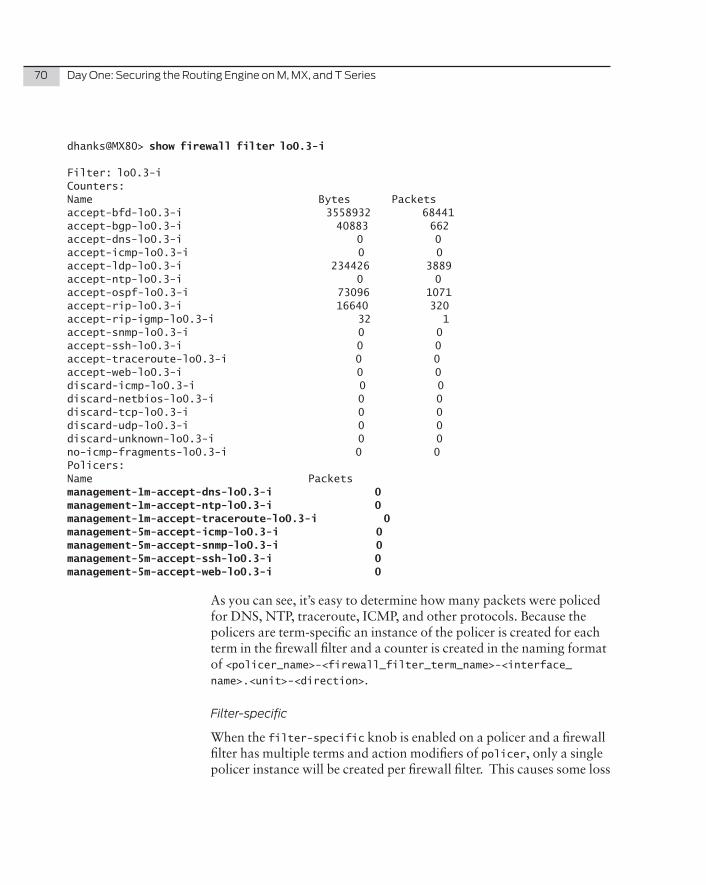
70 DayOne:SecuringtheRoutingEngineonM,MX,andTSeries
dhanks@MX80> show firewall filter lo0.3-i
Filter: lo0.3-i Counters:Name Bytes Packetsaccept-bfd-lo0.3-i 3558932 68441accept-bgp-lo0.3-i 40883 662accept-dns-lo0.3-i 0 0accept-icmp-lo0.3-i 0 0accept-ldp-lo0.3-i 234426 3889accept-ntp-lo0.3-i 0 0accept-ospf-lo0.3-i 73096 1071accept-rip-lo0.3-i 16640 320accept-rip-igmp-lo0.3-i 32 1accept-snmp-lo0.3-i 0 0accept-ssh-lo0.3-i 0 0accept-traceroute-lo0.3-i 0 0accept-web-lo0.3-i 0 0discard-icmp-lo0.3-i 0 0discard-netbios-lo0.3-i 0 0discard-tcp-lo0.3-i 0 0discard-udp-lo0.3-i 0 0discard-unknown-lo0.3-i 0 0no-icmp-fragments-lo0.3-i 0 0Policers:Name Packets management-1m-accept-dns-lo0.3-i 0management-1m-accept-ntp-lo0.3-i 0management-1m-accept-traceroute-lo0.3-i 0management-5m-accept-icmp-lo0.3-i 0management-5m-accept-snmp-lo0.3-i 0management-5m-accept-ssh-lo0.3-i 0management-5m-accept-web-lo0.3-i 0
As you can see, it’s easy to determine how many packets were policed for DNS, NTP, traceroute, ICMP, and other protocols. Because the policers are term-specific an instance of the policer is created for each term in the firewall filter and a counter is created in the naming format of <policer_name>-<firewall_filter_term_name>-<interface_name>.<unit>-<direction>.
Filter-specific
When the filter-specific knob is enabled on a policer and a firewall filter has multiple terms and action modifiers of policer, only a single policer instance will be created per firewall filter. This causes some loss
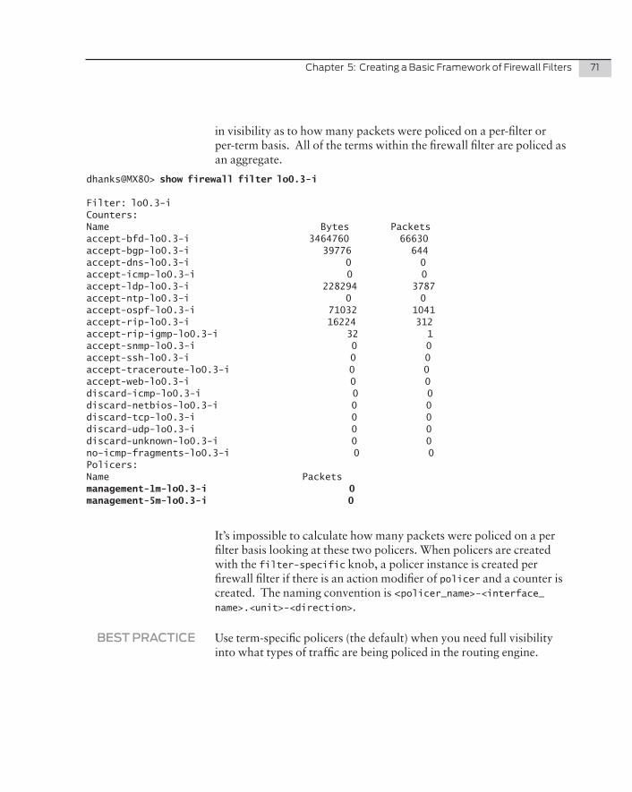
Chapter5:CreatingaBasicFrameworkofFirewallFilters 71
in visibility as to how many packets were policed on a per-filter or per-term basis. All of the terms within the firewall filter are policed as an aggregate.
dhanks@MX80> show firewall filter lo0.3-i
Filter: lo0.3-i Counters:Name Bytes Packetsaccept-bfd-lo0.3-i 3464760 66630accept-bgp-lo0.3-i 39776 644accept-dns-lo0.3-i 0 0accept-icmp-lo0.3-i 0 0accept-ldp-lo0.3-i 228294 3787accept-ntp-lo0.3-i 0 0accept-ospf-lo0.3-i 71032 1041accept-rip-lo0.3-i 16224 312accept-rip-igmp-lo0.3-i 32 1accept-snmp-lo0.3-i 0 0accept-ssh-lo0.3-i 0 0accept-traceroute-lo0.3-i 0 0accept-web-lo0.3-i 0 0discard-icmp-lo0.3-i 0 0discard-netbios-lo0.3-i 0 0discard-tcp-lo0.3-i 0 0discard-udp-lo0.3-i 0 0discard-unknown-lo0.3-i 0 0no-icmp-fragments-lo0.3-i 0 0Policers:Name Packets management-1m-lo0.3-i 0management-5m-lo0.3-i 0
It’s impossible to calculate how many packets were policed on a per filter basis looking at these two policers. When policers are created with the filter-specific knob, a policer instance is created per firewall filter if there is an action modifier of policer and a counter is created. The naming convention is <policer_name>-<interface_name>.<unit>-<direction>.
BEST�PRACTICE Use term-specific policers (the default) when you need full visibility into what types of traffic are being policed in the routing engine.
72 DayOne:SecuringtheRoutingEngineonM,MX,andTSeries
Management1Mbps
The management policer management-1m will restrict traffic to 1 Mbps and discard any packets that exceed this bandwidth limit. This policer will be applied to protocols such as NTP, traceroute, RADIUS, TACAS+, and telnet. Traditionally these protocols do not require high throughput so they are a good candidate for this policer:
policer management-1m { apply-flags omit; if-exceeding { bandwidth-limit 1m; burst-size-limit 625k; } then discard;}
Management5Mbps
The management policer management-5m is identical to the previous policer, except that traffic will have a bandwidth limit of 5 Mbps. Protocols such as ICMP, SNMP, HTTP, and SSH require higher throughput and 5 Mbps is adequate for accessing the router via SSH and copying configuration files via SCP:
policer management-5m { apply-flags omit; if-exceeding { bandwidth-limit 5m; burst-size-limit 625k; } then discard;}
ALERT! It’s recommended to remove any policer from SSH if you need to copy any large files to the routing engine such as a Junos firmware image.
Firewall Filters
Now it’s time to begin creating the fundamental building blocks to securing the routing engine. Each firewall filter is specific to a routing protocol or service – in other words, no firewall filter restricts traffic outside of its immediate focus. Examine the framework gathered so far as illustrated in Figure 5.3.
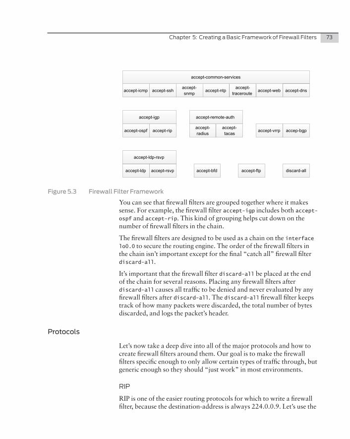
Chapter5:CreatingaBasicFrameworkofFirewallFilters 73
accept-icmp accept-sshaccept-snmp
accept-ntpaccept-
tracerouteaccept-web
accept-common-services
accept-ospf accept-rip
accept-igp
accept-radius
accept-tacas
accept-remote-auth
accept-vrrp accep-bgp
accept-bfd discard-allaccept-ldp accept-rsvp accept-ftp
accept-dns
accept-ldp-rsvp
Figure�5.3� Firewall�Filter�Framework
You can see that firewall filters are grouped together where it makes sense. For example, the firewall filter accept-igp includes both accept-ospf and accept-rip. This kind of grouping helps cut down on the number of firewall filters in the chain.
The firewall filters are designed to be used as a chain on the interface lo0.0 to secure the routing engine. The order of the firewall filters in the chain isn’t important except for the final “catch all” firewall filter discard-all.
It’s important that the firewall filter discard-all be placed at the end of the chain for several reasons. Placing any firewall filters after discard-all causes all traffic to be denied and never evaluated by any firewall filters after discard-all. The discard-all firewall filter keeps track of how many packets were discarded, the total number of bytes discarded, and logs the packet’s header.
Protocols
Let’s now take a deep dive into all of the major protocols and how to create firewall filters around them. Our goal is to make the firewall filters specific enough to only allow certain types of traffic through, but generic enough so they should “just work” in most environments.
RIP
RIP is one of the easier routing protocols for which to write a firewall filter, because the destination-address is always 224.0.0.9. Let’s use the
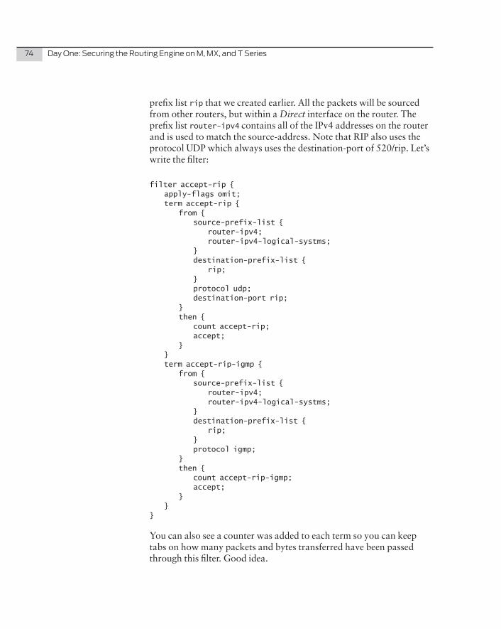
74 DayOne:SecuringtheRoutingEngineonM,MX,andTSeries
prefix list rip that we created earlier. All the packets will be sourced from other routers, but within a Direct interface on the router. The prefix list router-ipv4 contains all of the IPv4 addresses on the router and is used to match the source-address. Note that RIP also uses the protocol UDP which always uses the destination-port of 520/rip. Let’s write the filter:
filter accept-rip { apply-flags omit; term accept-rip { from { source-prefix-list { router-ipv4; router-ipv4-logical-systms; } destination-prefix-list { rip; } protocol udp; destination-port rip; } then { count accept-rip; accept; } } term accept-rip-igmp { from { source-prefix-list { router-ipv4; router-ipv4-logical-systms; } destination-prefix-list { rip; } protocol igmp; } then { count accept-rip-igmp; accept; } }}
You can also see a counter was added to each term so you can keep tabs on how many packets and bytes transferred have been passed through this filter. Good idea.
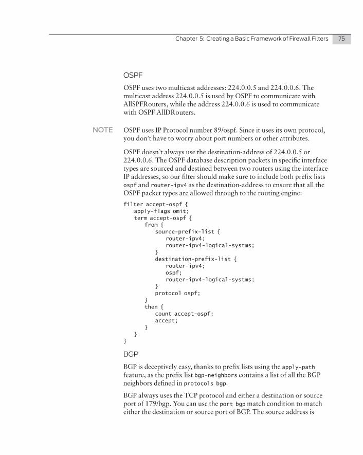
Chapter5:CreatingaBasicFrameworkofFirewallFilters 75
OSPF
OSPF uses two multicast addresses: 224.0.0.5 and 224.0.0.6. The multicast address 224.0.0.5 is used by OSPF to communicate with AllSPFRouters, while the address 224.0.0.6 is used to communicate with OSPF AllDRouters.
NOTE OSPF uses IP Protocol number 89/ospf. Since it uses its own protocol, you don’t have to worry about port numbers or other attributes.
OSPF doesn’t always use the destination-address of 224.0.0.5 or 224.0.0.6. The OSPF database description packets in specific interface types are sourced and destined between two routers using the interface IP addresses, so our filter should make sure to include both prefix lists ospf and router-ipv4 as the destination-address to ensure that all the OSPF packet types are allowed through to the routing engine:
filter accept-ospf { apply-flags omit; term accept-ospf { from { source-prefix-list { router-ipv4; router-ipv4-logical-systms; } destination-prefix-list { router-ipv4; ospf; router-ipv4-logical-systms; } protocol ospf; } then { count accept-ospf; accept; } }}
BGP
BGP is deceptively easy, thanks to prefix lists using the apply-path feature, as the prefix list bgp-neighbors contains a list of all the BGP neighbors defined in protocols bgp.
BGP always uses the TCP protocol and either a destination or source port of 179/bgp. You can use the port bgp match condition to match either the destination or source port of BGP. The source address is
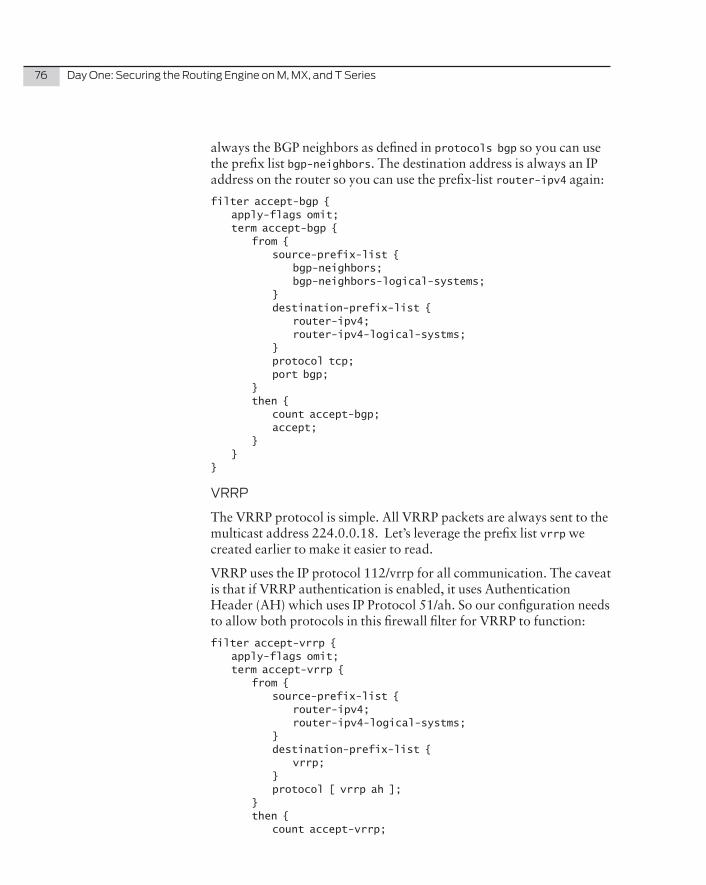
76 DayOne:SecuringtheRoutingEngineonM,MX,andTSeries
always the BGP neighbors as defined in protocols bgp so you can use the prefix list bgp-neighbors. The destination address is always an IP address on the router so you can use the prefix-list router-ipv4 again:
filter accept-bgp { apply-flags omit; term accept-bgp { from { source-prefix-list { bgp-neighbors; bgp-neighbors-logical-systems; } destination-prefix-list { router-ipv4; router-ipv4-logical-systms; } protocol tcp; port bgp; } then { count accept-bgp; accept; } }}
VRRP
The VRRP protocol is simple. All VRRP packets are always sent to the multicast address 224.0.0.18. Let’s leverage the prefix list vrrp we created earlier to make it easier to read.
VRRP uses the IP protocol 112/vrrp for all communication. The caveat is that if VRRP authentication is enabled, it uses Authentication Header (AH) which uses IP Protocol 51/ah. So our configuration needs to allow both protocols in this firewall filter for VRRP to function:
filter accept-vrrp { apply-flags omit; term accept-vrrp { from { source-prefix-list { router-ipv4; router-ipv4-logical-systms; } destination-prefix-list { vrrp; } protocol [ vrrp ah ]; } then { count accept-vrrp;
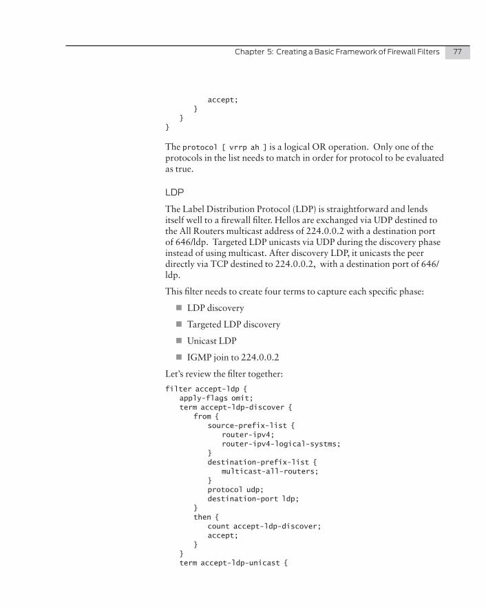
Chapter5:CreatingaBasicFrameworkofFirewallFilters 77
accept; } }}
The protocol [ vrrp ah ] is a logical OR operation. Only one of the protocols in the list needs to match in order for protocol to be evaluated as true.
LDP
The Label Distribution Protocol (LDP) is straightforward and lends itself well to a firewall filter. Hellos are exchanged via UDP destined to the All Routers multicast address of 224.0.0.2 with a destination port of 646/ldp. Targeted LDP unicasts via UDP during the discovery phase instead of using multicast. After discovery LDP, it unicasts the peer directly via TCP destined to 224.0.0.2, with a destination port of 646/ldp.
This filter needs to create four terms to capture each specific phase:
�� LDP discovery
�� Targeted LDP discovery
�� Unicast LDP
�� IGMP join to 224.0.0.2
Let’s review the filter together:
filter accept-ldp { apply-flags omit; term accept-ldp-discover { from { source-prefix-list { router-ipv4; router-ipv4-logical-systms; } destination-prefix-list { multicast-all-routers; } protocol udp; destination-port ldp; } then { count accept-ldp-discover; accept; } } term accept-ldp-unicast {
78 DayOne:SecuringtheRoutingEngineonM,MX,andTSeries
from { destination-prefix-list { router-ipv4; router-ipv4-logical-systms; } protocol tcp; port ldp; } then { count accept-ldp-unicast; accept; } } term accept-tldp-discover { from { destination-prefix-list { router-ipv4; router-ipv4-logical-systms; } protocol udp; destination-port ldp; } then { count accept-tldp-discover; accept; } } term accept-ldp-igmp { from { source-prefix-list { router-ipv4; router-ipv4-logical-systms; } destination-prefix-list { multicast-all-routers; } protocol igmp; } then { count accept-ldp-igmp; accept; } } }
RSVP
The Resource Reservation Protocol (RSVP) is a transport layer protocol that uses IP protocol number 46. Traffic is always destined to the router so the filter can use the prefix list router-ipv4:
Chapter5:CreatingaBasicFrameworkofFirewallFilters 79
filter accept-rsvp { apply-flags omit; term accept-rsvp { from { destination-prefix-list { router-ipv4; router-ipv4-logical-systms; } protocol rsvp; } then { count accept-rsvp; accept; } }}
BFD
The Bidirectional Forwarding Protocol (BFD) uses UDP to transmit packets. There’s a very specific range of ports that BFD is allowed to use for both the source and destination ports: the source ports allowed are 49152 through 65535 and the destination ports allowed are 3784 through 3785, which you’ll see as part of the filter configuration:
filter accept-bfd { apply-flags omit; term accept-bfd { from { source-prefix-list { router-ipv4; router-ipv4-logical-systms; } destination-prefix-list { router-ipv4; router-ipv4-logical-systms; } protocol udp; source-port 49152-65535; destination-port 3784-3785; } then { count accept-bfd; accept; } }}
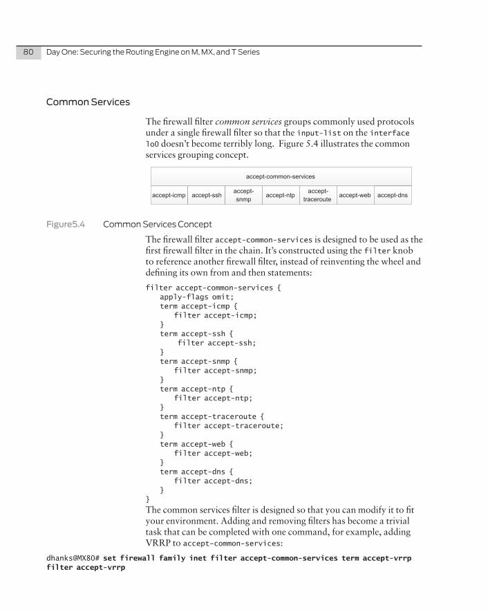
80 DayOne:SecuringtheRoutingEngineonM,MX,andTSeries
Common Services
The firewall filter common services groups commonly used protocols under a single firewall filter so that the input-list on the interface lo0 doesn’t become terribly long. Figure 5.4 illustrates the common services grouping concept.
accept-icmp accept-sshaccept-snmp
accept-ntpaccept-
tracerouteaccept-web
accept-common-services
accept-dns
Figure5.4 CommonServicesConcept
The firewall filter accept-common-services is designed to be used as the first firewall filter in the chain. It’s constructed using the filter knob to reference another firewall filter, instead of reinventing the wheel and defining its own from and then statements:
filter accept-common-services { apply-flags omit; term accept-icmp { filter accept-icmp; } term accept-ssh { filter accept-ssh; } term accept-snmp { filter accept-snmp; } term accept-ntp { filter accept-ntp; } term accept-traceroute { filter accept-traceroute; } term accept-web { filter accept-web; } term accept-dns { filter accept-dns; }}
The common services filter is designed so that you can modify it to fit your environment. Adding and removing filters has become a trivial task that can be completed with one command, for example, adding VRRP to accept-common-services:
dhanks@MX80# set firewall family inet filter accept-common-services term accept-vrrp filter accept-vrrp
Chapter5:CreatingaBasicFrameworkofFirewallFilters 81
This command adds a term to the end of the accept-common-services filter called accept-vrrp and references the existing firewall filter accept-vrrp.
ICMP
The Internet Control Message Protocol (ICMP) is one of the core protocols in IP to signal errors and query messages. ICMP packets are very small in nature and there’s no legitimate need to fragment these packets, so the first step in creating an ICMP filter is to match ICMP fragments, count and log them, and silently discard the packet.
Which ICMP types to allow into your network is a decision that you need to make. Some network operators like to be good network citizens and return meaningful error messages back to the sender, while other operators may prefer a more secure approach of not responding to errors or queries, keeping the sender in the dark.
Since ICMP is used primarily for errors and queries, by nature it shouldn’t consume a lot of resources. Best practice is to rate-limit the number of ICMP packets that enter the router. Let’s use the generic management policer of 5 Mbps:
filter accept-icmp { apply-flags omit; term no-icmp-fragments { from { is-fragment; protocol icmp; } then { count no-icmp-fragments; log; discard; } } term accept-icmp { from { protocol icmp; icmp-type [ echo-reply echo-request time-exceeded unreachable source-quench router-advertisement parameter-problem ]; } then { policer management-5m; count accept-icmp; accept; } }}
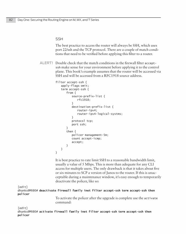
82 DayOne:SecuringtheRoutingEngineonM,MX,andTSeries
SSH
The best practice to access the router will always be SSH, which uses port 22/ssh and the TCP protocol. There are a couple of match condi-tions that need to be verified before applying this filter to a router.
ALERT! Double check that the match conditions in the firewall filter accept-ssh make sense for your environment before applying it to the control plane. This book’s example assumes that the router will be accessed via SSH and will be accessed from a RFC1918 source address.
filter accept-ssh { apply-flags omit; term accept-ssh { from { source-prefix-list { rfc1918; } destination-prefix-list { router-ipv4; router-ipv4-logical-systms; } protocol tcp; port ssh; } then { policer management-5m; count accept-icmp; accept; } }}
It is best practice to rate limit SSH to a reasonable bandwidth limit, usually a value of 5 Mbps. This is more than adequate for any CLI access for multiple users. The only drawback is that it takes about five or six minutes to SCP a version of Junos to the router. If this is unac-ceptable during a maintenance window, it’s easy enough to temporarily deactivate the policer, like so:
[edit]dhanks@MX80# deactivate firewall family inet filter accept-ssh term accept-ssh then policer
To activate the policer after the upgrade is complete use the activate command:
[edit]dhanks@MX80# activate firewall family inet filter accept-ssh term accept-ssh then policer
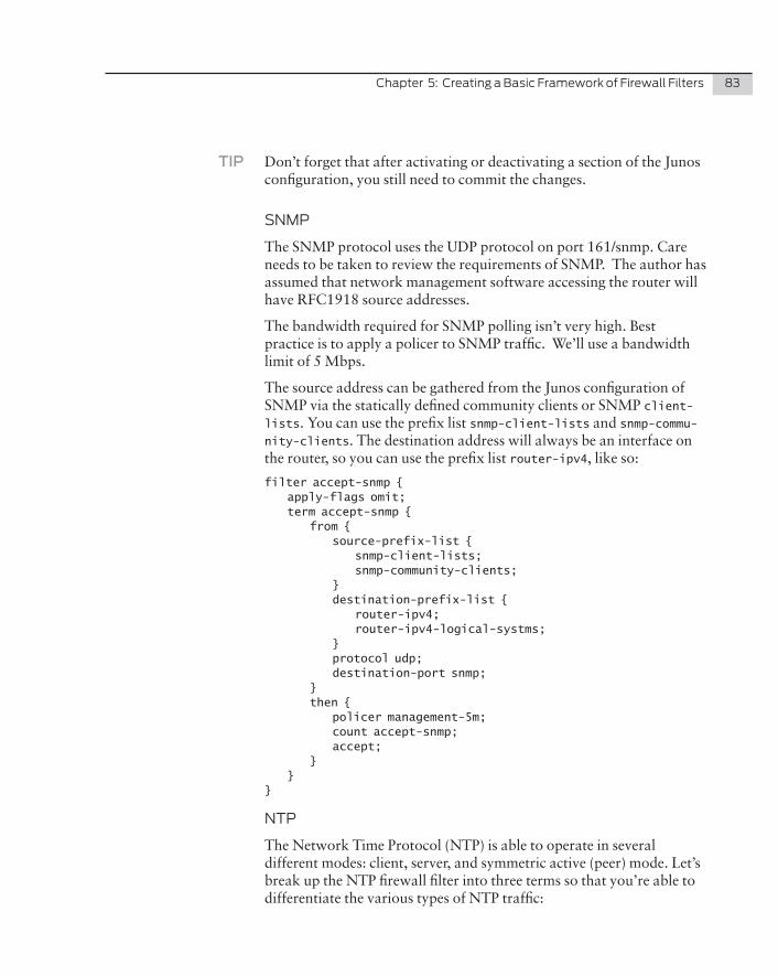
Chapter5:CreatingaBasicFrameworkofFirewallFilters 83
TIP Don’t forget that after activating or deactivating a section of the Junos configuration, you still need to commit the changes.
SNMP
The SNMP protocol uses the UDP protocol on port 161/snmp. Care needs to be taken to review the requirements of SNMP. The author has assumed that network management software accessing the router will have RFC1918 source addresses.
The bandwidth required for SNMP polling isn’t very high. Best practice is to apply a policer to SNMP traffic. We’ll use a bandwidth limit of 5 Mbps.
The source address can be gathered from the Junos configuration of SNMP via the statically defined community clients or SNMP client-lists. You can use the prefix list snmp-client-lists and snmp-commu-nity-clients. The destination address will always be an interface on the router, so you can use the prefix list router-ipv4, like so:
filter accept-snmp { apply-flags omit; term accept-snmp { from { source-prefix-list { snmp-client-lists; snmp-community-clients; } destination-prefix-list { router-ipv4; router-ipv4-logical-systms; } protocol udp; destination-port snmp; } then { policer management-5m; count accept-snmp; accept; } }}
NTP
The Network Time Protocol (NTP) is able to operate in several different modes: client, server, and symmetric active (peer) mode. Let’s break up the NTP firewall filter into three terms so that you’re able to differentiate the various types of NTP traffic:
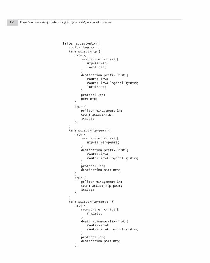
84 DayOne:SecuringtheRoutingEngineonM,MX,andTSeries
filter accept-ntp { apply-flags omit; term accept-ntp { from { source-prefix-list { ntp-server; localhost; } destination-prefix-list { router-ipv4; router-ipv4-logical-systms; localhost; } protocol udp; port ntp; } then { policer management-1m; count accept-ntp; accept; } } term accept-ntp-peer { from { source-prefix-list { ntp-server-peers; } destination-prefix-list { router-ipv4; router-ipv4-logical-systms; } protocol udp; destination-port ntp; } then { policer management-1m; count accept-ntp-peer; accept; } } term accept-ntp-server { from { source-prefix-list { rfc1918; } destination-prefix-list { router-ipv4; router-ipv4-logical-systms; } protocol udp; destination-port ntp; }
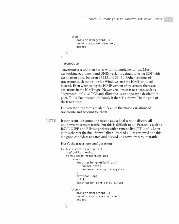
Chapter5:CreatingaBasicFrameworkofFirewallFilters 85
then { policer management-1m; count accept-ntp-server; accept; } } }
Traceroute
Traceroute is a tool that varies wildly in implementation. Most networking equipment and UNIX variants default to using UDP with destination ports between 33435 and 33450. Other versions of traceroute, such as the one for Windows, use the ICMP protocol instead. Even when using the ICMP version of traceroute there are variations in the ICMP type. Newer versions of traceroute, such as “tcptraceroute”, use TCP and allow the user to specify a destination port. Tools like this come in handy if there is a firewall in the path of the traceroute.
Let’s create three terms to identify all of the major variations of traceroute and account for them.
NOTE It may seem like common sense to add a final term to discard all unknown traceroute traffic, but this is difficult to do. Protocols such as RSVP, OSPF, and RIP use packets with a time to live (TTL) of 1. Later in this chapter the final firewall filter “discard-all” is reviewed and this is a good candidate to catch and discard unknown traceroute traffic.
Here’s the traceroute configuration:
filter accept-traceroute { apply-flags omit; term accept-traceroute-udp { from { destination-prefix-list { router-ipv4; router-ipv4-logical-systms; } protocol udp; ttl 1; destination-port 33435-33450; } then { policer management-1m; count accept-traceroute-udp; accept; } }
86 DayOne:SecuringtheRoutingEngineonM,MX,andTSeries
term accept-traceroute-icmp { from { destination-prefix-list { router-ipv4; router-ipv4-logical-systms; } protocol icmp; ttl 1; icmp-type [ echo-request timestamp time-exceeded ]; } then { policer management-1m; count accept-traceroute-icmp; accept; } } term accept-traceroute-tcp { from { destination-prefix-list { router-ipv4; router-ipv4-logical-systms; } protocol tcp; ttl 1; } then { policer management-1m; count accept-traceroute-tcp; accept; } }}
All traffic identified as traceroute is matched and accounted for. The traceroute packets are also policed down to 1 Mbps so that the routing engine isn’t wasting CPU cycles responding to low-priority traffic.
Web
Junos allows for different types of management access. To allow J-Web with a firewall filter, you just need to match TCP packets that are destined to ports 80/http or 443/https. Let’s police all J-Web traffic to 5 Mbps, as the service isn’t that bandwidth intensive.
filter accept-web { apply-flags omit; term accept-web { from { source-prefix-list {
Chapter5:CreatingaBasicFrameworkofFirewallFilters 87
rfc1918; } destination-prefix-list { router-ipv4; router-ipv4-logical-systms; } protocol tcp; destination-port [ http https ]; } then { policer management-5m; count accept-web; accept; } }}
DNS
Junos uses the Domain Name System (DNS) to lookup hostnames from IP addresses. This traffic is initiated from Junos to the external DNS server, so let’s create a firewall filter to match the return traffic. The DNS server replies back with a source port of 53/dns. Let’s leverage the prefix list dns-servers to match the DNS name servers already defined in the Junos configuration:
filter accept-dns { apply-flags omit; term accept-dns { from { source-prefix-list { dns-servers; } destination-prefix-list { router-ipv4; router-ipv4-logical-systms; } protocol udp; source-port 53; } then { policer management-1m; count accept-dns; accept; } }}
DNS queries are very small packets and shouldn’t use a lot of band-width, so install a 1 Mbps policer for all DNS traffic.
88 DayOne:SecuringtheRoutingEngineonM,MX,andTSeries
Less Common Services
Two of the less common services used are FTP and telnet. These are insecure protocols as they transmit data in clear text. These services weren’t included in the firewall filter accept-common-services because there are better alternatives. Instead of using FTP or telnet, it’s much easier to use SSH. SSH uses the Diffie-Hellman key exchange and provides a secure transport for both command-line access and copying files.
ALERT! Do not use the following firewall filters unless absolutely necessary. FTP and telnet are insecure and pass data in clear text. Please use SSH and SCP instead.
FTP
The File Transfer Protocol (FTP) has two modes of operation: passive and active. The primary difference is how the data port is negotiated and established. With active mode, the FTP client connects from a random unprivileged port (N) to the FTP server’s command port (21). The FTP client then listens on data port N+1. The FTP server then initiates a connection to the FTP client on port N+1.
Creating a stateless firewall filter for active FTP is straightforward. FTP uses the TCP protocol and the ports are always 20/ftp-data and 21/ftp, depending on whether the router is acting as a FTP server or client.
Firewall filters are stateless by default. It’s out of the scope of the book to create a stateful firewall filter.
ALERT! This firewall filter isn’t required to allow Junos to be an FTP client. Later in this chapter, the firewall filter accept-tcp-established will allow Junos to act as a FTP client.
filter accept-ftp { apply-flags omit; term accept-ftp { from { source-prefix-list { rfc1918; } destination-prefix-list { router-ipv4; router-ipv4-logical-systms; } protocol tcp;
Chapter5:CreatingaBasicFrameworkofFirewallFilters 89
port [ ftp ftp-data ]; } then { policer management-5m; count accept-ftp; accept; } }}
Telnet
The author was reluctant to include this filter, but understands there’s always a case for its use. Telnet uses the TCP protocol and traffic is always destined to port 23/telnet.
ALERT! Don’t use the firewall filter accept-telnet unless you know what you’re doing.
filter accept-telnet { apply-flags omit; term accept-telnet { from { source-prefix-list { rfc1918; } destination-prefix-list { router-ipv4; router-ipv4-logical-systms; } protocol tcp; destination-port telnet; } then { policer management-1m; count accept-telnet; accept; } }}
Telnet isn’t a bandwidth intensive protocol so you should police it down to 1 Mbps.
Catch All
There is now a large framework of firewall filters, policers, and prefix lists to allow specified traffic into the routing engine such as OSPF, BGP, and SSH. Yet there will always be traffic that will ultimately not
90 DayOne:SecuringtheRoutingEngineonM,MX,andTSeries
match any of the filters applied to the routing engine. So to gain visibility into the traffic that is destined to the routing engine, but not explicitly allowed by the framework, there are three catch all firewall filters that can be applied at the very end of the firewall filter chain: TCP Established, Discard All, and Accept All.
TCPEstablished
It’s important to note that these firewall filters have been designed to be applied to the ingress traffic on the routing engine. Traffic egressing the routing engine such as SSH, FTP, fetch, and TFTP is assumed to be trusted.
To match the return traffic that the routing engine initiated, you need to create a firewall filter that accepts TCP traffic that’s considered tcp-established, which is synonymous with TCP flags matching ACK or RST.
You could simply create a firewall filter that allowed any TCP packets with the ACK or RST in the TCP flags, but it would be better to under-stand which protocols and services the packets belong to.
To gain visibility into the different protocols, the firewall filter breaks accept-established into seven terms:
�� SSH: The term accept-tcp-established-ssh will match SSH return traffic back into the routing engine. The protocol will always be TCP with a source port of 22.
�� FTP: The term accept-tcp-established-ftp will accept return traffic from the FTP command port. This will always be the TCP protocol with a source port of 21/ftp.
�� FTP DATA TCP-INITIAL: Before the file transfer begins, there needs to be a negotiation of which FTP data port to use. The FTP server will initiate a connection to the router. This will always use the TCP protocol with the TCP flags SYN without an ACK. The synonym for this TCP flag is tcp-initial. The source port will always be 20/ftp-data.
�� FTP DATA: After the FTP server has opened a data port to the router, data can be transferred. This traffic will always use the TCP protocol, have the TCP flags ACK or RST (tcp-established), and have the source port of 20/ftp-data.
�� TELNET: The telnet protocol always uses TCP and when used from the command-line to connect to a remote host, the return
Chapter5:CreatingaBasicFrameworkofFirewallFilters 91
traffic will always have the source port of 23/telnet and the tcp-established TCP flags.
�� FETCH: Junos supports a fetch command in the shell that allows the administrator to download HTTP or HTTPS content to the routing engine. Junos also supports CLI options to remotely download configurations with the load command while in con-figuration mode.
�� The HTTP or HTTPS traffic will always use the TCP protocol, have a source port of either 80/http or 443/https, and have the tcp-established TCP flags.
�� EPHEMERAL: Protocols such as the Trivial File Transfer Proto-col (TFTP) will use UDP with a destination port of 69/tftp. An important note is that the server and client will negotiate ephem-eral ports to be used for the data transfer. IANA suggests ports 49152 through 65535 to be used as dynamic and/or private ports.
ALERT! The author has found that the ephemeral port range of 49152-65535 works well for TFTP, but operating systems such as Linux and Windows can use different ranges of ephemeral ports. If you need to support additional protocols or operating systems that support a different range of ephemeral ports, you need to change the values in the term accept-ephemeral.
And here’s the filter configuration:
filter accept-established { term accept-established-tcp-ssh { from { destination-prefix-list { router-ipv4; router-ipv4-logical-systms; } source-port ssh; tcp-established; } then { policer management-5m; count accept-established-tcp-ssh; accept; } } term accept-established-tcp-ftp { from { destination-prefix-list { router-ipv4;
92 DayOne:SecuringtheRoutingEngineonM,MX,andTSeries
router-ipv4-logical-systms; } source-port ftp; tcp-established; } then { policer management-5m; count accept-established-tcp-ftp; accept; } } term accept-established-tcp-ftp-data-syn { from { destination-prefix-list { router-ipv4; router-ipv4-logical-systms; } source-port ftp-data; tcp-initial; } then { policer management-5m; count accept-established-tcp-ftp-data-syn; accept; } } term accept-established-tcp-ftp-data { from { destination-prefix-list { router-ipv4; router-ipv4-logical-systms; } source-port ftp-data; tcp-established; } then { policer management-5m; count accept-established-tcp-ftp-data; accept; } } term accept-established-tcp-telnet { from { destination-prefix-list { router-ipv4; router-ipv4-logical-systms; } source-port telnet; tcp-established; } then { policer management-5m;
Chapter5:CreatingaBasicFrameworkofFirewallFilters 93
count accept-established-tcp-telnet; accept; } } term accept-established-tcp-fetch { from { destination-prefix-list { router-ipv4; router-ipv4-logical-systms; } source-port [ http https ]; tcp-established; } then { policer management-5m; count accept-established-tcp-fetch; accept; } } term accept-established-udp-ephemeral { from { destination-prefix-list { router-ipv4; router-ipv4-logical-systms; } protocol udp; destination-port 49152-65535; } then { policer management-5m; count accept-established-udp-ephemeral; accept; } }}
It may seem easier to create a filter that simply accepts all TCP traffic with the tcp-established flag. The drawback to this method is that all return traffic would be aggregated and the network operator wouldn’t be able to gain visibility into the traffic.
DiscardAll
The last firewall filter of the catch all is discard-all. The purpose of this filter is to simply partition packets into protocol categories that the routing engine isn’t interested in and discard the packets silently.
The firewall filter discard-all should be the very last filter in the firewall filter chain applied to the input-list on the loopback inter-face.
94 DayOne:SecuringtheRoutingEngineonM,MX,andTSeries
ALERT! If the firewall filter discard-all isn’t applied at the very end of the input-list chain, you will inadvertently drop all traffic destined to the routing engine without visibility.
The filter discard-all is the last line of defense to the routing engine. It’s important that this filter arm the administrator with detailed statistics regarding what packets were denied.
The filter breaks discard-all into seven terms: discard-ip-options; discard-TTL_1-unknown; discard-tcp; discard-netbios; discard-udp; discard-icmp; and finally discard-unknown. Each term has a counter named after the term so that you know how many bytes and packets have been discarded. The packet header will also be logged twice. The first log is the PFE, allowing you to quickly check and see detailed packet header information with the show firewall log command. The second log is exported to the syslog servers defined in system syslog host, allowing storage and archival of the offending traffic that can be analyzed and reported on by tools such as Juniper’s Security Threat Response Manager (STRM).
MORE? For more information about Juniper STRM see http://www.juniper.net/us/en/products-services/security/strm-series/ .
And here is the discard-all filter’s configuration:
filter discard-all { apply-flags omit; term discard-ip-options { from { ip-options any; } then { count discard-ip-options; log; syslog; discard; } } term discard-TTL_1-unknown { from { ttl 1; } then { count discard-all-TTL_1-unknown; log; syslog; discard; } }
Chapter5:CreatingaBasicFrameworkofFirewallFilters 95
term discard-tcp { from { protocol tcp; } then { count discard-tcp; log; syslog; discard; } } term discard-netbios { from { protocol udp; destination-port 137; } then { count discard-netbios; log; syslog; discard; } } term discard-udp { from { protocol udp; } then { count discard-udp; log; syslog; discard; } } term discard-icmp { from { protocol icmp; } then { count discard-icmp; log; syslog; discard; } } term discard-unknown { then { count discard-unknown; log; syslog; discard; }
96 DayOne:SecuringtheRoutingEngineonM,MX,andTSeries
}}
To demonstrate the power of the discard-all firewall filter, let’s send some traffic to the routing engine that will be discarded, and then view how many packets and bytes were discarded, as well as any detailed packet header information.
Let’s use a web browser and point it at the router via the URL http://172.16.1.11:666. Since there’s no firewall filter allowing TCP traffic destined to port 666, it should be caught by the catch all firewall filter discard-all.
Since the term discard-tcp in the filter has an action modifier of syslog, let’s take a look at the remote syslog server and view the packet header information:
Apr 02 22:43:13 172.16.1.11 Apr 3 05:42:49 /kernel: FW: fxp0.0 D tcp 172.16.1.100 172.16.1.11 53232 666Apr 02 22:43:17 172.16.1.11 Apr 3 05:42:52 /kernel: FW: fxp0.0 D tcp 172.16.1.100 172.16.1.11 53232 666Apr 02 22:43:24 172.16.1.11 Apr 3 05:42:58 /kernel: FW: fxp0.0 D tcp 172.16.1.100 172.16.1.11 53232 666
You could also confirm the same information by viewing the firewall log:
dhanks@MX80> show firewall log Log :Time Filter Action Interface Protocol Src Addr Dest Addr05:42:58 lo0.0-i D fxp0.0 TCP 172.16.1.100 172.16.1.1105:42:52 lo0.0-i D fxp0.0 TCP 172.16.1.100 172.16.1.1105:42:49 lo0.0-i D fxp0.0 TCP 172.16.1.100 172.16.1.11
You can also see the three packets were found by the counter discard-tcp-lo0.0-i:
dhanks@MX80> show firewall filter lo0.0-i counter discard-tcp-lo0.0-i
Filter: lo0.0-i Counters:Name Bytes Packetsdiscard-tcp-lo0.0-i 152 3
dhanks@MX80>
AcceptAll
The firewall filter accept-all is the exact opposite of discard-all. It exists as an alternative to discard-all if the administrator is in a
Chapter5:CreatingaBasicFrameworkofFirewallFilters 97
production environment and needs to err on the side of caution when applying firewall filters to the routing engine. Use the filter accept-all in place of discard-all at the very end of the firewall filter chain.
NOTE The firewall filter accept-all is a safe alternative to discard-all as it will accept, log, and count all traffic. Only use accept-all if you’re in a production environment and need to verify that the previous firewall filters in the chain are working as expected. The filter accept-all exists so that the administrator can see any traffic that was not explicitly accepted by previous filters in the chain and make corrections if necessary.
The filter is broken down by protocols and has an unknown catch-all at the very end to ensure that all traffic is accepted.
ALERT! Once you verify that all traffic is being matched by firewall filters before the accept-all, it’s recommended to immediately remove accept-all and replace it with discard-all since the entire point is to secure the routing engine.
And here is the accept-all configuration:
filter accept-all { apply-flags omit; term accept-all-tcp { from { protocol tcp; } then { count accept-all-tcp; log; syslog; accept; } } term accept-all-udp { from { protocol udp; } then { count accept-all-udp; log; syslog; accept; } } term accept-all-igmp { from {
98 DayOne:SecuringtheRoutingEngineonM,MX,andTSeries
protocol igmp; } then { count accept-all-igmp; log; syslog; accept; } } term accept-icmp { from { protocol icmp; } then { count accept-all-icmp; log; syslog; accept; } } term accept-all-unknown { then { count accept-all-unknown; log; syslog; accept; } }}
Each type of protocol is separated into different terms and counters. All traffic is logged to both the PFE and syslog for analysis. Any traffic that can’t be identified will be accepted by the last term accept-all-unknown.
Summary
This chapter has demonstrated how to create a framework of firewall filters that can be used to secure various types of routers. The filters have been designed to be used in a firewall filter chain. The next-to- last filter should be the filter accept-established. When traffic is sourced from the routing engine, return traffic needs to be let back in. The last filter in the chain should be one of the two “catch all” filters: accept-all or discard-all.
Chapter 6
Applying Security Policies to the Routing Engine
Before You Begin . . . . . . . . . . . . . . . . . . . . . . . . . . . . . . . . . . . . . . . . . . . . . . . . 101
Load Configuration . . . . . . . . . . . . . . . . . . . . . . . . . . . . . . . . . . . . . . . . . . . . . . 101
Your First Security Policy . . . . . . . . . . . . . . . . . . . . . . . . . . . . . . . . . . . . . . . . . 103
Advanced Security Policy . . . . . . . . . . . . . . . . . . . . . . . . . . . . . . . . . . . . . . . . 110
Summary . . . . . . . . . . . . . . . . . . . . . . . . . . . . . . . . . . . . . . . . . . . . . . . . . . . . . . . .121
100 DayOne:SecuringtheRoutingEngineonM,MX,andTSeries
Building a framework to secure the routing engine that’s portable, simple, yet customized to meet the requirements of the majority of networks has required the integration of a lot of moving parts. Here’s a quick summary of what you’ve accomplished so far:
�� Chapter 1: Firewall Filters: This chapter explained firewall filters in detail – how they match traffic, perform actions, and how they’re evaluated. You also reviewed intermediate to expert level topics such as nested firewall filter, and firewall chaining.
�� Chapter 2: Policers: This chapter introduced policers and how they rate limit traffic. You reviewed the Token Bucket algorithm in detail so that we could configure bandwidth-limit and burst-size-limit with confidence. You closed the chapter with how policer instances are created and how to influence the number of policers per firewall filter.
�� Chapter 3: Viewing Counters, Logs, and Policers: This chapter demonstrated how to view counters, logs, and policers. You reviewed the Junos counter and policer naming convention.
�� Chapter 4: Junos Configuration Automation: This chapter introduced a powerful Junos configuration automation tool called apply-path. You created example configuration and generated dynamic prefix lists based on the content of the Junos configuration.
�� Chapter 5: Creating a Basic Framework of Firewall Filters: This chapter built upon the previous chapters and introduced the concept of a framework that’s capable of providing building blocks that can be used in any combination to provide custom security to the routing engine. Each firewall filter within the framework was reviewed in detail.
Now let’s take all of the material you’ve learned in Chapters 1 through 5 and apply a security policy to our router.
This book includes a complete example configuration located in the appendix, and you’ll start by taking this configuration and loading it into your router. Then you will test a very simple security framework on a single router and gradually move up to a multiple router environ-ment running multiple protocols and services.
TIP If you are following along on your router, a special Copy and Paste edition of this book can be downloaded from this book’s page at www.
Chapter6:ApplyingSecurityPoliciestotheRoutingEngine 101
juniper.net/dayone. Its rich-text format allows you to copy and paste the firewall filter configurations without having to key them in again.
Before You Begin
Adding firewall filters to the routing engine shouldn’t be taken lightly. Any mistake could leave your router isolated and possibly require a connection to the console port to remove the offending firewall filter. This book calls out these specific pitfalls and warnings along the way.
Applying the configuration for the first time, however, needs to be done on a lab router, as this book has advocated all along. This way, if there are any mistakes they will be isolated to the laboratory equip-ment and not impact your production network.
Load Configuration
Let’s start off by loading the framework configuration.
Please reference the configuration listed in the Appendix: Framework Configuration. The configuration includes prefix lists, firewall filters, and policers.
To Load the Configuration
1. Log in to the router and enter configuration mode.
dhanks@MX80> configure Entering configuration mode
[edit]dhanks@MX80#
2. Copy (CTRL-C) the entire configuration as shown in the Appendix, Framework Configuration. Use the load merge relative terminal command to import the configuration into your router.
dhanks@MX80# load merge relative terminal [Type ̂ D at a new line to end input]
3. Paste (CTRL-V) the configuration into the terminal. Press enter a couple of times after the entire configuration has been pasted into the terminal. Now type CTRL-D to end the load command.
<paste framework configuration>CTRL-Dload complete
102 DayOne:SecuringtheRoutingEngineonM,MX,andTSeries
[edit]dhanks@MX80#
4. Use the show firewall command to verify that the configuration has been imported correctly. The firewall filters should appear exactly as below with the apply-flags omit.
[edit]dhanks@MX80# show firewall family inet { filter accept-bgp { /* OMITTED */ }; filter accept-ospf { /* OMITTED */ }; filter accept-rip { /* OMITTED */ }; filter accept-vrrp { /* OMITTED */ }; filter accept-icmp { /* OMITTED */ }; filter accept-ssh { /* OMITTED */ }; filter accept-snmp { /* OMITTED */ }; filter accept-ntp { /* OMITTED */ }; filter accept-web { /* OMITTED */ }; filter discard-all { /* OMITTED */ }; filter accept-traceroute { /* OMITTED */ }; filter accept-igp { /* OMITTED */ }; filter accept-common-services { /* OMITTED */ }; filter accept-bfd { /* OMITTED */ }; filter accept-ldp { /* OMITTED */ }; filter accept-ftp { /* OMITTED */ }; filter accept-rsvp { /* OMITTED */ }; filter accept-radius { /* OMITTED */ }; filter accept-tacas { /* OMITTED */ }; filter accept-remote-auth { /* OMITTED */ }; filter accept-telnet { /* OMITTED */ }; filter accept-dns { /* OMITTED */ }; filter accept-ldp-rsvp { /* OMITTED */ }; filter accept-established { /* OMITTED */ };}policer management-1m { /* OMITTED */ };policer management-5m { /* OMITTED */ };
[edit]dhanks@MX80#
5. Delete any existing firewall filters from your lo0.0 interface.
[edit]dhanks@MX80# delete interfaces lo0.0 family inet filter
6. Use the commit check command to ensure that the new configuration is syntactically correct and there are no errors.
dhanks@MX80# commit check configuration check succeeds
Chapter6:ApplyingSecurityPoliciestotheRoutingEngine 103
7.Commit the configuration now that it has cleared the check.
dhanks@MX80# commitcommit complete[edit]dhanks@MX80#
NOTE If there were any errors during the load command, make sure that you correctly copied the entire configuration and pasted the entire configu-ration into your terminal.
TIP If there are still load errors, it may be because there are existing prefix lists, firewalls, or policers that are causing a naming conflict.
At this point your router should have a fully working framework for applying security to the routing engine. At the moment nothing is being secured because we deleted any existing filters applied to the interface lo0.0.
Your First Security Policy
Our first security policy will be very simple and only deal with one router. You’ll apply the firewall filter accept-common-services and also include both “catch all” filters accept-established and discard-all.
The first filter includes the following services: ICMP, traceroute, SSH, SNMP, NTP, web, and DNS.
To Build the First Security Policy
1. Apply the firewall filter accept-common-services as the first filter in the input-list chain on the interface lo0.0.
[edit]dhanks@MX80# set interfaces lo0.0 family inet filter input-list accept-common-services
2. Apply the first catch all firewall filter accept-established.
[edit]dhanks@MX80# set interfaces lo0.0 family inet filter input-list accept-established
3. Apply the second catch all firewall filter discard-all.
[edit]dhanks@MX80# set interfaces lo0.0 family inet filter input-list discard-all
4. Verify the changes with show compare.
dhanks@MX80# show | compare

104 DayOne:SecuringtheRoutingEngineonM,MX,andTSeries
[edit interfaces lo0 unit 0 family inet]+ filter {+ input-list [ accept-common-services accept-established discard-all ];+ }
[edit]dhanks@MX80#
5. Commit the changes using the confirmed feature. If there are any problems after the commit, the configuration will automatically rollback after 5 minutes.
dhanks@MX80# commit confirmed 5 commit confirmed will be automatically rolled back in 5 minutes unless confirmedcommit complete
# commit confirmed will be rolled back in 5 minutes[edit]dhanks@MX80#
6. After verifying that you still have connectivity to the router, issue the commit command again to confirm the configuration.
[edit]dhanks@MX80# commit commit complete
You have now applied your first security framework to the router. Let’s take a look and see what’s happening under the hood. What traffic is being allowed? Is there any traffic being denied? Take what you learned in Chapter 3 and begin reviewing the firewall counters, policers, and logs.
Let’s take a look at the firewall filters applied to the routing engine by using the show firewall filter command:
dhanks@MX80> show firewall filter lo0.0-i
Filter: lo0.0-i Counters:Name Bytes Packetsaccept-established-tcp-fetch-lo0.0-i 0 0accept-established-tcp-ftp-lo0.0-i 0 0accept-established-tcp-ftp-data-lo0.0-i 0 0accept-established-tcp-ftp-data-syn-lo0.0-i 0 0accept-established-tcp-ssh-lo0.0-i 0 0accept-established-tcp-telnet-lo0.0-i 0 0accept-established-udp-ephemeral-lo0.0-i 0 0accept-icmp-lo0.0-i 0 0accept-ntp-lo0.0-i 0 0accept-ntp-server-lo0.0-i 0 0accept-snmp-lo0.0-i 0 0accept-ssh-lo0.0-i 3848 52
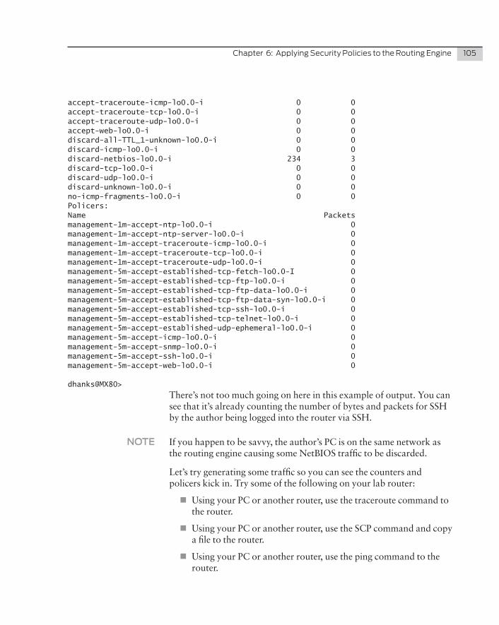
Chapter6:ApplyingSecurityPoliciestotheRoutingEngine 105
accept-traceroute-icmp-lo0.0-i 0 0accept-traceroute-tcp-lo0.0-i 0 0accept-traceroute-udp-lo0.0-i 0 0accept-web-lo0.0-i 0 0discard-all-TTL_1-unknown-lo0.0-i 0 0discard-icmp-lo0.0-i 0 0 discard-netbios-lo0.0-i 234 3discard-tcp-lo0.0-i 0 0discard-udp-lo0.0-i 0 0discard-unknown-lo0.0-i 0 0no-icmp-fragments-lo0.0-i 0 0Policers:Name Packets management-1m-accept-ntp-lo0.0-i 0management-1m-accept-ntp-server-lo0.0-i 0management-1m-accept-traceroute-icmp-lo0.0-i 0management-1m-accept-traceroute-tcp-lo0.0-i 0 management-1m-accept-traceroute-udp-lo0.0-i 0management-5m-accept-established-tcp-fetch-lo0.0-I 0management-5m-accept-established-tcp-ftp-lo0.0-i 0management-5m-accept-established-tcp-ftp-data-lo0.0-i 0management-5m-accept-established-tcp-ftp-data-syn-lo0.0-i 0management-5m-accept-established-tcp-ssh-lo0.0-i 0management-5m-accept-established-tcp-telnet-lo0.0-i 0management-5m-accept-established-udp-ephemeral-lo0.0-i 0management-5m-accept-icmp-lo0.0-i 0management-5m-accept-snmp-lo0.0-i 0management-5m-accept-ssh-lo0.0-i 0management-5m-accept-web-lo0.0-i 0
dhanks@MX80>
There’s not too much going on here in this example of output. You can see that it’s already counting the number of bytes and packets for SSH by the author being logged into the router via SSH.
NOTE If you happen to be savvy, the author’s PC is on the same network as the routing engine causing some NetBIOS traffic to be discarded.
Let’s try generating some traffic so you can see the counters and policers kick in. Try some of the following on your lab router:
�� Using your PC or another router, use the traceroute command to the router.
�� Using your PC or another router, use the SCP command and copy a file to the router.
�� Using your PC or another router, use the ping command to the router.
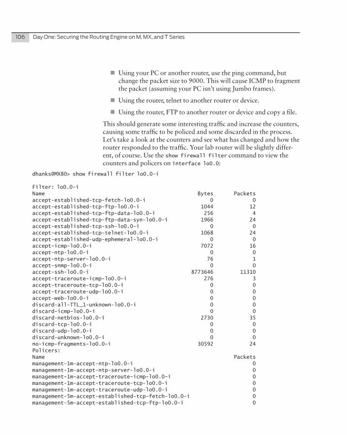
106 DayOne:SecuringtheRoutingEngineonM,MX,andTSeries
�� Using your PC or another router, use the ping command, but change the packet size to 9000. This will cause ICMP to fragment the packet (assuming your PC isn’t using Jumbo frames).
�� Using the router, telnet to another router or device.
�� Using the router, FTP to another router or device and copy a file.
This should generate some interesting traffic and increase the counters, causing some traffic to be policed and some discarded in the process. Let’s take a look at the counters and see what has changed and how the router responded to the traffic. Your lab router will be slightly differ-ent, of course. Use the show firewall filter command to view the counters and policers on interface lo0.0:
dhanks@MX80> show firewall filter lo0.0-i
Filter: lo0.0-i Name Bytes Packetsaccept-established-tcp-fetch-lo0.0-i 0 0accept-established-tcp-ftp-lo0.0-i 1044 12accept-established-tcp-ftp-data-lo0.0-i 256 4accept-established-tcp-ftp-data-syn-lo0.0-i 1966 24accept-established-tcp-ssh-lo0.0-i 0 0accept-established-tcp-telnet-lo0.0-i 1068 24accept-established-udp-ephemeral-lo0.0-i 0 0accept-icmp-lo0.0-i 7072 16accept-ntp-lo0.0-i 0 0accept-ntp-server-lo0.0-i 76 1accept-snmp-lo0.0-i 0 0accept-ssh-lo0.0-i 8773646 11310accept-traceroute-icmp-lo0.0-i 276 3accept-traceroute-tcp-lo0.0-i 0 0accept-traceroute-udp-lo0.0-i 0 0accept-web-lo0.0-i 0 0discard-all-TTL_1-unknown-lo0.0-i 0 0discard-icmp-lo0.0-i 0 0discard-netbios-lo0.0-i 2730 35discard-tcp-lo0.0-i 0 0discard-udp-lo0.0-i 0 0discard-unknown-lo0.0-i 0 0no-icmp-fragments-lo0.0-i 30592 24Policers:Name Packets management-1m-accept-ntp-lo0.0-i 0management-1m-accept-ntp-server-lo0.0-i 0management-1m-accept-traceroute-icmp-lo0.0-i 0management-1m-accept-traceroute-tcp-lo0.0-i 0management-1m-accept-traceroute-udp-lo0.0-i 0management-5m-accept-established-tcp-fetch-lo0.0-i 0management-5m-accept-established-tcp-ftp-lo0.0-i 0
Chapter6:ApplyingSecurityPoliciestotheRoutingEngine 107
management-5m-accept-established-tcp-ftp-data-lo0.0-i 0management-5m-accept-established-tcp-ftp-data-syn-lo0.0-i 0management-5m-accept-established-tcp-ssh-lo0.0-i 0management-5m-accept-established-tcp-telnet-lo0.0-i 0management-5m-accept-established-udp-ephemeral-lo0.0-i 0management-5m-accept-icmp-lo0.0-i 0management-5m-accept-snmp-lo0.0-i 0management-5m-accept-ssh-lo0.0-i 102management-5m-accept-web-lo0.0-i 0
dhanks@MX80>
A lot of things changed now that there’s traffic being sent to and from the routing engine. Let’s take a look at the changes task by task.
Using Your PC or Another Router, Use the traceroute Command to the Router
This task sent traffic towards the routing engine using the traceroute command and the author’s implementation of traceroute used ICMP. You can see that the counter accept-traceroute-icmp-lo0.0-i found three packets. This makes sense as traceroute sends three packets by default:
accept-traceroute-icmp-lo0.0-i 276 3
Using Your PC or Another Router, Use the SCP Command and Copy a File to the Router
This task is two-fold: it would increment the counter accept-ssh-lo0.0-i, but also invoke the policer that’s installed in the firewall filter accept-ssh, which is set to police traffic exceeding a bandwidth limit of 5 Mbps:
Counters:accept-ssh-lo0.0-i 8773646 11310Policers:management-5m-accept-ssh-lo0.0-i 102
Using Your PC or Another Router, Use the Ping Command to the Router
The ping command incremented the counter accept-icmp-lo0.0-i. No surprise there:
accept-icmp-lo0.0-i 7072 16
Using Your PC or Another Router, Use the Ping Command, but Change the Packet Size to 9000
This is an interesting task because the ping command is used in such a way that it would fragment the ICMP traffic. The firewall filter accept-
108 DayOne:SecuringtheRoutingEngineonM,MX,andTSeries
icmp and the first term no-icmp-fragments found these packets, incremented the counter, and discarded them:
no-icmp-fragments-lo0.0-i 30592 24
Use the show firewall log to See the Packet Headers of the Discarded Packets
dhanks@MX80> show firewall log Log :Time Filter Action Interface Protocol Src Addr Dest Addr03:43:11 lo0.0-i D fxp0.0 ICMP 172.16.1.100 172.16.1.1103:43:11 lo0.0-i D fxp0.0 ICMP 172.16.1.100 172.16.1.1103:43:11 lo0.0-i D fxp0.0 ICMP 172.16.1.100 172.16.1.1103:43:11 lo0.0-i D fxp0.0 ICMP 172.16.1.100 172.16.1.11
To get more detailed information, use the show firewall log detail command:
dhanks@MX80> show firewall log detailTime of Log: 2011-04-03 03:43:11 UTC, Filter: lo0.0-i, Filter action: discard, Name of interface: fxp0.0Name of protocol: ICMP, Packet Length: 48288, Source address: 172.16.1.100, Destination address: 172.16.1.11ICMP type: 0, ICMP code: 0Time of Log: 2011-04-03 03:43:11 UTC, Filter: lo0.0-i, Filter action: discard, Name of interface: fxp0.0Name of protocol: ICMP, Packet Length: 48288, Source address: 172.16.1.100, Destination address: 172.16.1.11ICMP type: 0, ICMP code: 0Time of Log: 2011-04-03 03:43:11 UTC, Filter: lo0.0-i, Filter action: discard, Name of interface: fxp0.0Name of protocol: ICMP, Packet Length: 48288, Source address: 172.16.1.100, Destination address: 172.16.1.11ICMP type: 0, ICMP code: 0Time of Log: 2011-04-03 03:43:11 UTC, Filter: lo0.0-i, Filter action: discard, Name of interface: fxp0.0Name of protocol: ICMP, Packet Length: 48288, Source address: 172.16.1.100, Destination address: 172.16.1.11ICMP type: 0, ICMP code: 0
Using the Router, telnet to Another Router or Device
This task was a bit different, because the router itself was used to generate traffic. The return telnet traffic was caught by the firewall filter accept-established term accept-established-tcp-telnet-lo0.0-i:
accept-established-tcp-telnet-lo0.0-i 1068 24
Chapter6:ApplyingSecurityPoliciestotheRoutingEngine 109
Using the Router, FTP to Another Router or Device and Copy a File
Again, traffic was generated from the router itself, but this time using FTP. This is a unique task because the firewall filter accept-estab-lished has three separate terms to match the return traffic:
�� accept-established-tcp-ftp: matches the FTP CMD port return traffic.
�� accept-established-tcp-ftp-data-syn: matches the first SYN packet initiated by the FTP server back to Junos.
�� accept-established-tcp-ftp-data: matches the return data used by the FTP data port.
accept-established-tcp-ftp-lo0.0-i 1044 12accept-established-tcp-ftp-data-lo0.0-i 256 4accept-established-tcp-ftp-data-syn-lo0.0-i 1966 24
Summary
With this simple framework it’s easy to see that the router only accepts traffic that it’s interested in. We also gain visibility into the routing engine and understand what type of traffic has been accepted, discard-ed, and policed.
Advanced Security Policy
Now it’s time to introduce more routers and protocols to the mix. We’ll create a firewall framework to support the following protocols:
�� OSPF
�� RIP
�� BGP
�� BFD
�� LDP
�� RSVP
This should be more than enough to demonstrate the power and flexibility of the Junos security framework.
For those of you who are following along on your lab router, this book is using a Juniper MX80 router, which supports a router virtualization feature called logical systems. R3 and R4 are logical systems defined within the same physical MX80 as shown in Figure 6.1.
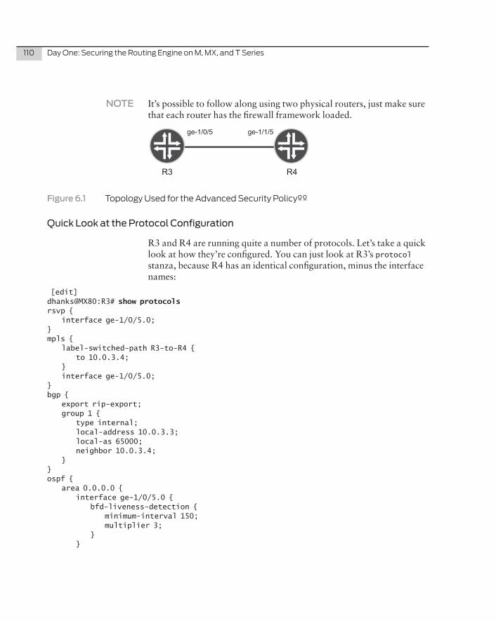
110 DayOne:SecuringtheRoutingEngineonM,MX,andTSeries
NOTE It’s possible to follow along using two physical routers, just make sure that each router has the firewall framework loaded.
ge-1/0/5 ge-1/1/5
R3 R4
Figure�6.1� TopologyUsedfortheAdvancedSecurityPolicyºº
Quick Look at the Protocol Configuration
R3 and R4 are running quite a number of protocols. Let’s take a quick look at how they’re configured. You can just look at R3’s protocol stanza, because R4 has an identical configuration, minus the interface names:
[edit]dhanks@MX80:R3# show protocols rsvp { interface ge-1/0/5.0;}mpls { label-switched-path R3-to-R4 { to 10.0.3.4; } interface ge-1/0/5.0;}bgp { export rip-export; group 1 { type internal; local-address 10.0.3.3; local-as 65000; neighbor 10.0.3.4; }}ospf { area 0.0.0.0 { interface ge-1/0/5.0 { bfd-liveness-detection { minimum-interval 150; multiplier 3; } }
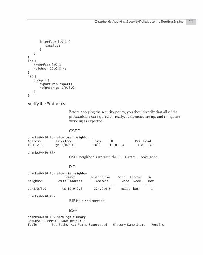
Chapter6:ApplyingSecurityPoliciestotheRoutingEngine 111
interface lo0.3 { passive; } }}ldp { interface lo0.3; neighbor 10.0.3.4;} rip { group 1 { export rip-export; neighbor ge-1/0/5.0; }}
Verify the Protocols
Before applying the security policy, you should verify that all of the protocols are configured correctly, adjacencies are up, and things are working as expected.
OSPF
dhanks@MX80:R3> show ospf neighbor Address Interface State ID Pri Dead10.0.2.6 ge-1/0/5.0 Full 10.0.3.4 128 37
dhanks@MX80:R3>
OSPF neighbor is up with the FULL state. Looks good.
RIP
dhanks@MX80:R3> show rip neighbor Source Destination Send Receive InNeighbor State Address Address Mode Mode Met -------- ----- ------- ----------- ---- ------- --- ge-1/0/5.0 Up 10.0.2.5 224.0.0.9 mcast both 1
dhanks@MX80:R3>
RIP is up and running.
BGP
dhanks@MX80:R3> show bgp summary Groups: 1 Peers: 1 Down peers: 0Table Tot Paths Act Paths Suppressed History Damp State Pending
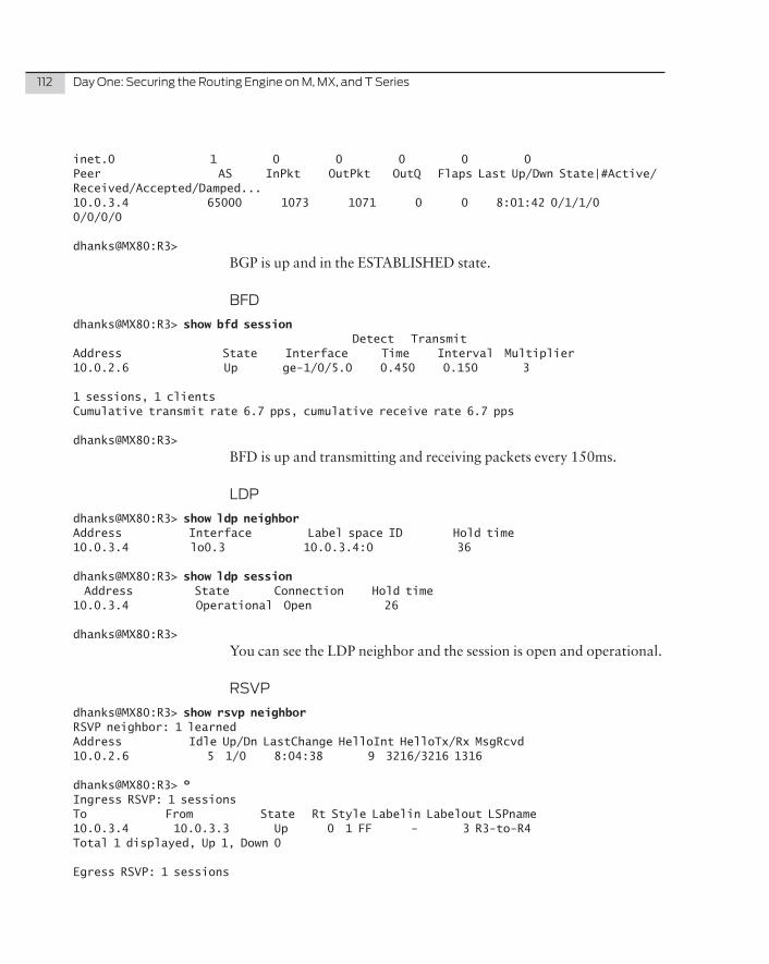
112 DayOne:SecuringtheRoutingEngineonM,MX,andTSeries
inet.0 1 0 0 0 0 0Peer AS InPkt OutPkt OutQ Flaps Last Up/Dwn State|#Active/Received/Accepted/Damped...10.0.3.4 65000 1073 1071 0 0 8:01:42 0/1/1/0 0/0/0/0
dhanks@MX80:R3>
BGP is up and in the ESTABLISHED state.
BFD
dhanks@MX80:R3> show bfd session Detect TransmitAddress State Interface Time Interval Multiplier10.0.2.6 Up ge-1/0/5.0 0.450 0.150 3
1 sessions, 1 clientsCumulative transmit rate 6.7 pps, cumulative receive rate 6.7 pps
dhanks@MX80:R3>
BFD is up and transmitting and receiving packets every 150ms.
LDP
dhanks@MX80:R3> show ldp neighbor Address Interface Label space ID Hold time10.0.3.4 lo0.3 10.0.3.4:0 36
dhanks@MX80:R3> show ldp session Address State Connection Hold time10.0.3.4 Operational Open 26
dhanks@MX80:R3>
You can see the LDP neighbor and the session is open and operational.
RSVP
dhanks@MX80:R3> show rsvp neighbor RSVP neighbor: 1 learnedAddress Idle Up/Dn LastChange HelloInt HelloTx/Rx MsgRcvd10.0.2.6 5 1/0 8:04:38 9 3216/3216 1316
dhanks@MX80:R3> º Ingress RSVP: 1 sessionsTo From State Rt Style Labelin Labelout LSPname 10.0.3.4 10.0.3.3 Up 0 1 FF - 3 R3-to-R4Total 1 displayed, Up 1, Down 0
Egress RSVP: 1 sessions
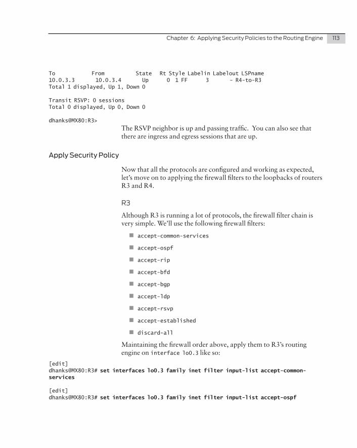
Chapter6:ApplyingSecurityPoliciestotheRoutingEngine 113
To From State Rt Style Labelin Labelout LSPname 10.0.3.3 10.0.3.4 Up 0 1 FF 3 - R4-to-R3Total 1 displayed, Up 1, Down 0
Transit RSVP: 0 sessionsTotal 0 displayed, Up 0, Down 0
dhanks@MX80:R3>
The RSVP neighbor is up and passing traffic. You can also see that there are ingress and egress sessions that are up.
Apply Security Policy
Now that all the protocols are configured and working as expected, let’s move on to applying the firewall filters to the loopbacks of routers R3 and R4.
R3
Although R3 is running a lot of protocols, the firewall filter chain is very simple. We’ll use the following firewall filters:
�� accept-common-services
�� accept-ospf
�� accept-rip
�� accept-bfd
�� accept-bgp
�� accept-ldp
�� accept-rsvp
�� accept-established
�� discard-all
Maintaining the firewall order above, apply them to R3’s routing engine on interface lo0.3 like so:
[edit]dhanks@MX80:R3# set interfaces lo0.3 family inet filter input-list accept-common-services
[edit]dhanks@MX80:R3# set interfaces lo0.3 family inet filter input-list accept-ospf
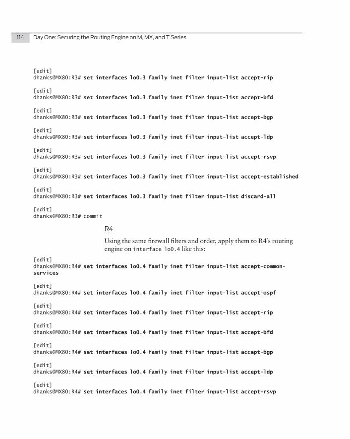
114 DayOne:SecuringtheRoutingEngineonM,MX,andTSeries
[edit]dhanks@MX80:R3# set interfaces lo0.3 family inet filter input-list accept-rip
[edit]dhanks@MX80:R3# set interfaces lo0.3 family inet filter input-list accept-bfd
[edit]dhanks@MX80:R3# set interfaces lo0.3 family inet filter input-list accept-bgp
[edit]dhanks@MX80:R3# set interfaces lo0.3 family inet filter input-list accept-ldp
[edit]dhanks@MX80:R3# set interfaces lo0.3 family inet filter input-list accept-rsvp
[edit]dhanks@MX80:R3# set interfaces lo0.3 family inet filter input-list accept-established
[edit]dhanks@MX80:R3# set interfaces lo0.3 family inet filter input-list discard-all
[edit]dhanks@MX80:R3# commit
R4
Using the same firewall filters and order, apply them to R4’s routing engine on interface lo0.4 like this:
[edit]dhanks@MX80:R4# set interfaces lo0.4 family inet filter input-list accept-common-services
[edit]dhanks@MX80:R4# set interfaces lo0.4 family inet filter input-list accept-ospf
[edit]dhanks@MX80:R4# set interfaces lo0.4 family inet filter input-list accept-rip
[edit]dhanks@MX80:R4# set interfaces lo0.4 family inet filter input-list accept-bfd
[edit]dhanks@MX80:R4# set interfaces lo0.4 family inet filter input-list accept-bgp
[edit]dhanks@MX80:R4# set interfaces lo0.4 family inet filter input-list accept-ldp
[edit]dhanks@MX80:R4# set interfaces lo0.4 family inet filter input-list accept-rsvp
Chapter6:ApplyingSecurityPoliciestotheRoutingEngine 115
[edit]dhanks@MX80:R4# set interfaces lo0.4 family inet filter input-list accept-established
[edit]dhanks@MX80:R4# set interfaces lo0.4 family inet filter input-list discard-all
[edit]dhanks@MX80:R4# commit
Verify R3 and R4
Now that R3 and R4 have a security framework applied to the routing engine, let’s double check that all the protocols are working as expect-ed again.
dhanks@MX80:R3> show ospf neighbor Address Interface State ID Pri Dead10.0.2.6 ge-1/0/5.0 Full 10.0.3.4 128 37
dhanks@MX80:R3>
dhanks@MX80:R3> show rip neighbor Source Destination Send Receive InNeighbor State Address Address Mode Mode Met -------- ----- ------- ----------- ---- ------- --- ge-1/0/5.0 Up 10.0.2.5 224.0.0.9 mcast both 1
dhanks@MX80:R3>
dhanks@MX80:R3> show bgp summary Groups: 1 Peers: 1 Down peers: 0Table Tot Paths Act Paths Suppressed History Damp State Pendinginet.0 1 0 0 0 0 0Peer AS InPkt OutPkt OutQ Flaps Last Up/Dwn State|#Active/Received/Accepted/Damped...10.0.3.4 65000 1125 1124 0 0 8:25:24 0/1/1/0 0/0/0/0
dhanks@MX80:R3>
dhanks@MX80:R3> show bfd session Detect TransmitAddress State Interface Time Interval Multiplier10.0.2.6 Up ge-1/0/5.0 0.450 0.150 3
1 sessions, 1 clientsCumulative transmit rate 6.7 pps, cumulative receive rate 6.7 pps
dhanks@MX80:R3>
dhanks@MX80:R3> show ldp neighbor
116 DayOne:SecuringtheRoutingEngineonM,MX,andTSeries
Address Interface Label space ID Hold time10.0.3.4 lo0.3 10.0.3.4:0 36
dhanks@MX80:R3> show ldp session Address State Connection Hold time10.0.3.4 Operational Open 26
dhanks@MX80:R3>
dhanks@MX80:R3> show rsvp neighbor RSVP neighbor: 1 learnedAddress Idle Up/Dn LastChange HelloInt HelloTx/Rx MsgRcvd10.0.2.6 0 1/0 8:26:51 9 3363/3363 1378
dhanks@MX80:R3> show rsvp session Ingress RSVP: 1 sessionsTo From State Rt Style Labelin Labelout LSPname 10.0.3.4 10.0.3.3 Up 0 1 FF - 3 R3-to-R4Total 1 displayed, Up 1, Down 0
Egress RSVP: 1 sessionsTo From State Rt Style Labelin Labelout LSPname 10.0.3.3 10.0.3.4 Up 0 1 FF 3 - R4-to-R3Total 1 displayed, Up 1, Down 0
Transit RSVP: 0 sessionsTotal 0 displayed, Up 0, Down 0
dhanks@MX80:R3>
Everything is up and running as expected. It looks like the security framework applied to R3 and R4 is working properly.
Viewing Counters, Logs, and Policers
Let’s take a look at the counters, logs, and policers on R3. You should expect to see the counters matching protocol traffic being incremented.
NOTE The author is using a virtualization feature called logical systems. All show firewall commands must be performed from the physical router and must then reference the specific logical system filter. The filter lo0.3-i refers to the logical-system R3.
dhanks@MX80> show firewall filter lo0.3-i
Filter: lo0.3-i Counters:
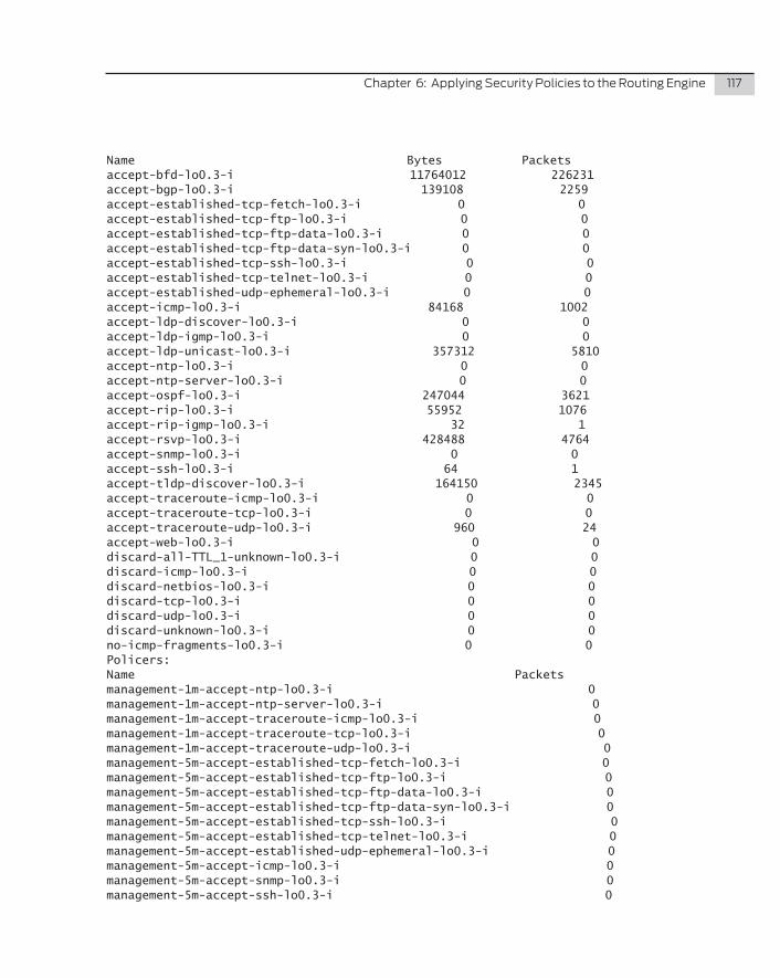
Chapter6:ApplyingSecurityPoliciestotheRoutingEngine 117
Name Bytes Packetsaccept-bfd-lo0.3-i 11764012 226231accept-bgp-lo0.3-i 139108 2259accept-established-tcp-fetch-lo0.3-i 0 0accept-established-tcp-ftp-lo0.3-i 0 0accept-established-tcp-ftp-data-lo0.3-i 0 0accept-established-tcp-ftp-data-syn-lo0.3-i 0 0accept-established-tcp-ssh-lo0.3-i 0 0accept-established-tcp-telnet-lo0.3-i 0 0accept-established-udp-ephemeral-lo0.3-i 0 0accept-icmp-lo0.3-i 84168 1002accept-ldp-discover-lo0.3-i 0 0accept-ldp-igmp-lo0.3-i 0 0accept-ldp-unicast-lo0.3-i 357312 5810accept-ntp-lo0.3-i 0 0accept-ntp-server-lo0.3-i 0 0accept-ospf-lo0.3-i 247044 3621accept-rip-lo0.3-i 55952 1076accept-rip-igmp-lo0.3-i 32 1accept-rsvp-lo0.3-i 428488 4764accept-snmp-lo0.3-i 0 0accept-ssh-lo0.3-i 64 1accept-tldp-discover-lo0.3-i 164150 2345accept-traceroute-icmp-lo0.3-i 0 0accept-traceroute-tcp-lo0.3-i 0 0accept-traceroute-udp-lo0.3-i 960 24accept-web-lo0.3-i 0 0discard-all-TTL_1-unknown-lo0.3-i 0 0discard-icmp-lo0.3-i 0 0discard-netbios-lo0.3-i 0 0discard-tcp-lo0.3-i 0 0discard-udp-lo0.3-i 0 0discard-unknown-lo0.3-i 0 0no-icmp-fragments-lo0.3-i 0 0Policers:Name Packets management-1m-accept-ntp-lo0.3-i 0management-1m-accept-ntp-server-lo0.3-i 0management-1m-accept-traceroute-icmp-lo0.3-i 0management-1m-accept-traceroute-tcp-lo0.3-i 0management-1m-accept-traceroute-udp-lo0.3-i 0management-5m-accept-established-tcp-fetch-lo0.3-i 0management-5m-accept-established-tcp-ftp-lo0.3-i 0management-5m-accept-established-tcp-ftp-data-lo0.3-i 0management-5m-accept-established-tcp-ftp-data-syn-lo0.3-i 0management-5m-accept-established-tcp-ssh-lo0.3-i 0management-5m-accept-established-tcp-telnet-lo0.3-i 0management-5m-accept-established-udp-ephemeral-lo0.3-i 0management-5m-accept-icmp-lo0.3-i 0management-5m-accept-snmp-lo0.3-i 0management-5m-accept-ssh-lo0.3-i 0
118 DayOne:SecuringtheRoutingEngineonM,MX,andTSeries
management-5m-accept-web-lo0.3-i 0
dhanks@MX80>
OSPF
The firewall filter accept-ospf is matching all of the OSPF traffic and incrementing the counter accept-ospf-lo0.3-i. You can see that the number of packets is incremented for every OSPF Hello packet:
dhanks@MX80> show firewall filter lo0.3-i counter accept-ospf-lo0.3-i
Filter: lo0.3-i Counters:Name Bytes Packetsaccept-ospf-lo0.3-i 250320 3669
Wait a few moments for an OSPF Hello Packet ...
dhanks@MX80> show firewall filter lo0.3-i counter accept-ospf-lo0.3-i
Filter: lo0.3-i Counters:Name Bytes Packetsaccept-ospf-lo0.3-i 250388 3670
dhanks@MX80>
Notice how the first command shows a total of 3669 packets have been counted. A few seconds later the same command was executed and the packets have increased to 3670.
RIP
RIP is being matched by the firewall filter accept-rip and the counter accept-rip-lo0.3-i is being incremented with every RIP update:
dhanks@MX80> show firewall filter lo0.3-i counter accept-rip-lo0.3-i
Filter: lo0.3-i Counters:Name Bytes Packetsaccept-rip-lo0.3-i 56784 1092
Wait a few moments for a RIP update ...
dhanks@MX80> show firewall filter lo0.3-i counter accept-rip-lo0.3-i
Filter: lo0.3-i Counters:Name Bytes Packetsaccept-rip-lo0.3-i 56836 1093
dhanks@MX80>
Chapter6:ApplyingSecurityPoliciestotheRoutingEngine 119
RIP started out with 1092 packets and after a moment the packets have increased to 1093.
BGP
The firewall filter accept-bgp is matching all of the BGP traffic being sent to R3. The counter accept-bgp-lo0.3-i is also being incremented with every BGP packet:
dhanks@MX80> show firewall filter lo0.3-i counter accept-bgp-lo0.3-i
Filter: lo0.3-i Counters:Name Bytes Packetsaccept-bgp-lo0.3-i 141814 2303
Wait a few moments ...
dhanks@MX80> show firewall filter lo0.3-i counter accept-bgp-lo0.3-i
Filter: lo0.3-i Counters:Name Bytes Packetsaccept-bgp-lo0.3-i 141885 2304
dhanks@MX80>
BFD
BFD is a light-weight protocol, but it sends packets at a high-rate. The firewall filter accept-bfd is matching all of the BFD traffic and the counter accept-bfd-lo0.3-i is being incremented with every BFD echo:
dhanks@MX80> show firewall filter lo0.3-i counter accept-bfd-lo0.3-i
Filter: lo0.3-i Counters:Name Bytes Packetsaccept-bfd-lo0.3-i 12037272 231486
Wait a few moments for some BFD echo packets ...
dhanks@MX80> show firewall filter lo0.3-i counter accept-bfd-lo0.3-i
Filter: lo0.3-i Counters:Name Bytes Packetsaccept-bfd-lo0.3-i 12038832 231516
dhanks@MX80>
120 DayOne:SecuringtheRoutingEngineonM,MX,andTSeries
LDP
The firewall filter accept-ldp has multiple terms to match LDP depend-ing on how it’s configured. Here, a targeted LDP is used in the configu-ration to demonstrate how the discover packets are separated from the unicast traffic. The counter accept-tldp-discover-lo0.3-i is incremented for every targeted LDP discovery packet. The counter accept-ldp-uni-cast-lo0.3-i is incremented for every LDP session packet:
dhanks@MX80> show firewall filter lo0.3-i counter accept-ldp-unicast-lo0.3-i
Filter: lo0.3-i Counters:Name Bytes Packetsaccept-ldp-unicast-lo0.3-i 365720 5944
Wait a few moments for a LDP Hello packet ...
dhanks@MX80> show firewall filter lo0.3-i counter accept-ldp-unicast-lo0.3-i
Filter: lo0.3-i Counters:Name Bytes Packetsaccept-ldp-unicast-lo0.3-i 365842 5946
Now let’s check out targeted LDP:
dhanks@MX80> show firewall filter lo0.3-i counter accept-tldp-discover-lo0.3-i
Filter: lo0.3-i Counters:Name Bytes Packetsaccept-tldp-discover-lo0.3-i 168910 2413
Wait a few moments for an LDP discover packet.
dhanks@MX80> show firewall filter lo0.3-i counter accept-tldp-discover-lo0.3-i
Filter: lo0.3-i Counters:Name Bytes Packetsaccept-tldp-discover-lo0.3-i 168980 2414
dhanks@MX80>
Chapter6:ApplyingSecurityPoliciestotheRoutingEngine 121
RSVP
RSVP is being matched by the firewall filter accept-rsvp. The counter accept-rsvp-lo0.3-i is also being incremented with every packet:
dhanks@MX80> show firewall filter lo0.3-i counter accept-rsvp-lo0.3-i
Filter: lo0.3-i Counters:Name Bytes Packetsaccept-rsvp-lo0.3-i 443084 4928
Wait a few moments for a RSVP hello packet ...
dhanks@MX80> show firewall filter lo0.3-i counter accept-rsvp-lo0.3-i
Filter: lo0.3-i Counters:Name Bytes Packetsaccept-rsvp-lo0.3-i 443308 4929
dhanks@MX80>
Summary
Although our topology only contained two routers, you could see the number of protocols increased the complexity. Applying the custom-ized firewall filters literally takes only one command per router:
dhanks@MX80:R3# set interfaces lo0.3 family inet filter input-list [ accept-common-services accept-ospf accept-rip accept-bfd accept-bgp accept-ldp accept-rsvp accept-established discard-all ]
dhanks@MX80:R4# set interfaces lo0.4 family inet filter input-list [ accept-common-services accept-ospf accept-rip accept-bfd accept-bgp accept-ldp accept-rsvp accept-established discard-all ]
Each router was able to fully function using a wide variety of proto-cols, while at the same time blocking any traffic that wasn’t explicitly configured or that exceeded a policer’s bandwidth limit.
No matter how complex the problem, it can always be broken down into simple building blocks. It’s much easier to pick and choose firewall filters from a framework than trying to build and maintain large
122 DayOne:SecuringtheRoutingEngineonM,MX,andTSeries
“protect-re” firewall filters that have to be customized for every router. Maintaining such a large “protect-re” requires too much work for every change in the network, because terms have to be copied into the configuration and moved around to ensure proper evaluation.
As your network changes, modifying the firewall framework is a trivial task. Because all of the building blocks are already preloaded on the router, it’s just a matter of applying them to the loopback interface.
The framework itself can and should be modified to meet the require-ments of your network. Try it yourself.
Appendix
Lessons Learned . . . . . . . . . . . . . . . . . . . . . . . . . . . . . . . . . . . . . . . . . . . . . . . . 124
Framework Configuration . . . . . . . . . . . . . . . . . . . . . . . . . . . . . . . . . . . . . . . . 125
R3 Configuration . . . . . . . . . . . . . . . . . . . . . . . . . . . . . . . . . . . . . . . . . . . . . . . . 143
R4 Configuration . . . . . . . . . . . . . . . . . . . . . . . . . . . . . . . . . . . . . . . . . . . . . . . . 145
124 DayOne:SecuringtheRoutingEngineonM,MX,andTSeries
If you’ve followed along with this book on a router, you know that creating a framework of firewall filters designed to secure the routing engine is hard work. Each protocol and service has their own little nuances, sometimes making a stateless firewall filter near impossible. It’s difficult to gauge how secure versus how broad to make each filter. There’s a tradeoff between portability and security. In this book, it was decided to err on the side of caution and chose portability over security in this book’s examples. Feel free to tighten the filters up to best secure your own environment.
Lessons Learned
Hopefully this book has showed you that maintaining a simple filter input-list is more natural than maintaining a single, gigantic “pro-tect-re” that’s over 800 lines long. The simplicity becomes more apparent as this solution is scaled across multiple routers.
Junos configuration automation using apply-path feature is a very powerful tool. Each firewall filter used a prefix list leveraging apply-path where possible. Using apply-path pushes the grunt work of updating changes into prefix lists off the shoulders of the administrator and onto Junos. When administrators perform scheduled maintenance at 3am to add twenty BGP neighbors, and turn up four new interfaces, the last thing the administrator needs to worry about modifying are the firewall filters responsible for securing the routing engine.
You should have also noticed that firewall filters that break down the incoming traffic by protocol, function, and role, provide better analysis and detailed statistics for the administrator to troubleshoot problems. There’s no such thing as too much data when it’s properly sorted and categorized.
The rest of this appendix contains the framework configuration for your inspection and use. First a few words of caution.
�� Care should always be taken when applying firewall filters to the routing engine.
�� Always double check your work.
�� Use the show | compare command liberally, to fully understand what’s being changed.
�� In production environments use the final firewall filter accept-all instead of the discard-all command, which allows you to
Appendix 125
spend time making sure that all your previous firewall filters in the chain are working as expected.
�� The router should be verified to work properly without incre-menting counters in the filter accept-all. After the verification is complete, it’s recommended to immediately remove the filter accept-all and replace it with discard-all to ensure the routing engine is secure.
But if you’ve read this book you know all this. Congratulations on securing your Junos routing engine!
TIP� If you visit www.juniper.net/dayone, and then follow the path to this book’s download page, you’ll find a free Copy and Paste edition of this book. Its rich-text format allows the file to be opened in various text editors for easy copying and pasting of the book’s configurations, such as the one that follows in this appendix.
Framework Configuration
policy-options { prefix-list router-ipv4 { apply-path “interfaces <*> unit <*> family inet address <*>”; } prefix-list bgp-neighbors { apply-path “protocols bgp group <*> neighbor <*>”; } prefix-list ospf { 224.0.0.5/32; 224.0.0.6/32; } prefix-list rfc1918 { 10.0.0.0/8; 172.16.0.0/12; 192.168.0.0/16; } prefix-list rip { 224.0.0.9/32; } prefix-list vrrp { 224.0.0.18/32; } prefix-list multicast-all-routers { 224.0.0.2/32; } prefix-list router-ipv4-logical-systms { apply-path “logical-systems <*> interfaces <*> unit <*> family inet address
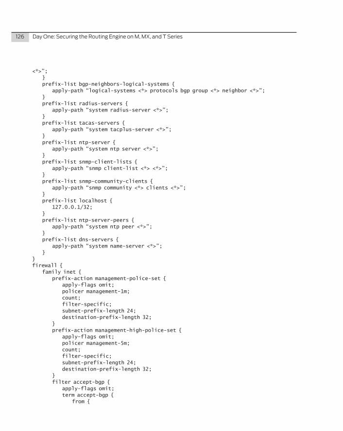
126 DayOne:SecuringtheRoutingEngineonM,MX,andTSeries
<*>”; } prefix-list bgp-neighbors-logical-systems { apply-path “logical-systems <*> protocols bgp group <*> neighbor <*>”; } prefix-list radius-servers { apply-path “system radius-server <*>”; } prefix-list tacas-servers { apply-path “system tacplus-server <*>”; } prefix-list ntp-server { apply-path “system ntp server <*>”; } prefix-list snmp-client-lists { apply-path “snmp client-list <*> <*>”; } prefix-list snmp-community-clients { apply-path “snmp community <*> clients <*>”; } prefix-list localhost { 127.0.0.1/32; } prefix-list ntp-server-peers { apply-path “system ntp peer <*>”; } prefix-list dns-servers { apply-path “system name-server <*>”; }}firewall { family inet { prefix-action management-police-set { apply-flags omit; policer management-1m; count; filter-specific; subnet-prefix-length 24; destination-prefix-length 32; } prefix-action management-high-police-set { apply-flags omit; policer management-5m; count; filter-specific; subnet-prefix-length 24; destination-prefix-length 32; } filter accept-bgp { apply-flags omit; term accept-bgp { from {
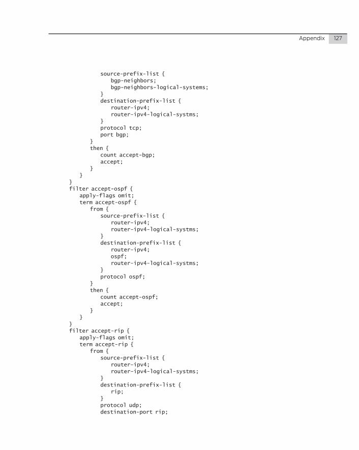
Appendix 127
source-prefix-list { bgp-neighbors; bgp-neighbors-logical-systems; } destination-prefix-list { router-ipv4; router-ipv4-logical-systms; } protocol tcp; port bgp; } then { count accept-bgp; accept; } } } filter accept-ospf { apply-flags omit; term accept-ospf { from { source-prefix-list { router-ipv4; router-ipv4-logical-systms; } destination-prefix-list { router-ipv4; ospf; router-ipv4-logical-systms; } protocol ospf; } then { count accept-ospf; accept; } } } filter accept-rip { apply-flags omit; term accept-rip { from { source-prefix-list { router-ipv4; router-ipv4-logical-systms; } destination-prefix-list { rip; } protocol udp; destination-port rip;
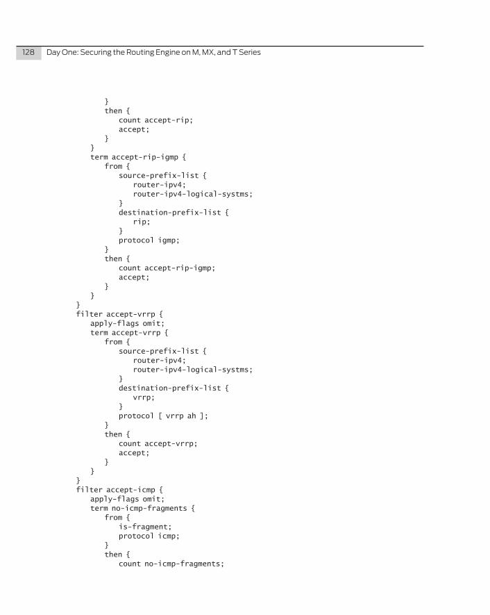
128 DayOne:SecuringtheRoutingEngineonM,MX,andTSeries
} then { count accept-rip; accept; } } term accept-rip-igmp { from { source-prefix-list { router-ipv4; router-ipv4-logical-systms; } destination-prefix-list { rip; } protocol igmp; } then { count accept-rip-igmp; accept; } } } filter accept-vrrp { apply-flags omit; term accept-vrrp { from { source-prefix-list { router-ipv4; router-ipv4-logical-systms; } destination-prefix-list { vrrp; } protocol [ vrrp ah ]; } then { count accept-vrrp; accept; } } } filter accept-icmp { apply-flags omit; term no-icmp-fragments { from { is-fragment; protocol icmp; } then { count no-icmp-fragments;
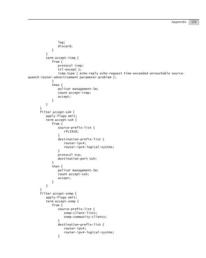
Appendix 129
log; discard; } } term accept-icmp { from { protocol icmp; ttl-except 1; icmp-type [ echo-reply echo-request time-exceeded unreachable source-quench router-advertisement parameter-problem ]; } then { policer management-5m; count accept-icmp; accept; } } } filter accept-ssh { apply-flags omit; term accept-ssh { from { source-prefix-list { rfc1918; } destination-prefix-list { router-ipv4; router-ipv4-logical-systms; } protocol tcp; destination-port ssh; } then { policer management-5m; count accept-ssh; accept; } } } filter accept-snmp { apply-flags omit; term accept-snmp { from { source-prefix-list { snmp-client-lists; snmp-community-clients; } destination-prefix-list { router-ipv4; router-ipv4-logical-systms; }
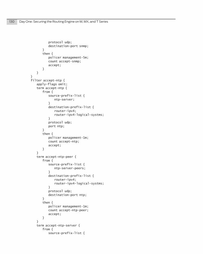
130 DayOne:SecuringtheRoutingEngineonM,MX,andTSeries
protocol udp; destination-port snmp; } then { policer management-5m; count accept-snmp; accept; } } } filter accept-ntp { apply-flags omit; term accept-ntp { from { source-prefix-list { ntp-server; } destination-prefix-list { router-ipv4; router-ipv4-logical-systms; } protocol udp; port ntp; } then { policer management-1m; count accept-ntp; accept; } } term accept-ntp-peer { from { source-prefix-list { ntp-server-peers; } destination-prefix-list { router-ipv4; router-ipv4-logical-systms; } protocol udp; destination-port ntp; } then { policer management-1m; count accept-ntp-peer; accept; } } term accept-ntp-server { from { source-prefix-list {
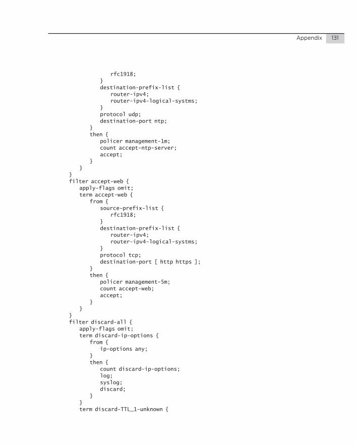
Appendix 131
rfc1918; } destination-prefix-list { router-ipv4; router-ipv4-logical-systms; } protocol udp; destination-port ntp; } then { policer management-1m; count accept-ntp-server; accept; } } } filter accept-web { apply-flags omit; term accept-web { from { source-prefix-list { rfc1918; } destination-prefix-list { router-ipv4; router-ipv4-logical-systms; } protocol tcp; destination-port [ http https ]; } then { policer management-5m; count accept-web; accept; } } } filter discard-all { apply-flags omit; term discard-ip-options { from { ip-options any; } then { count discard-ip-options; log; syslog; discard; } } term discard-TTL_1-unknown {
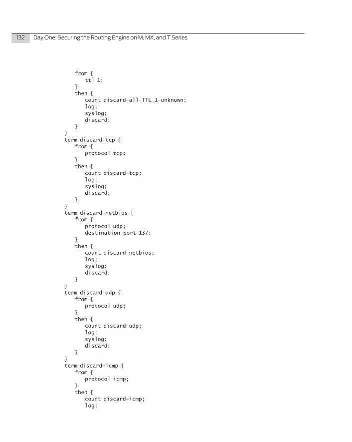
132 DayOne:SecuringtheRoutingEngineonM,MX,andTSeries
from { ttl 1; } then { count discard-all-TTL_1-unknown; log; syslog; discard; } } term discard-tcp { from { protocol tcp; } then { count discard-tcp; log; syslog; discard; } } term discard-netbios { from { protocol udp; destination-port 137; } then { count discard-netbios; log; syslog; discard; } } term discard-udp { from { protocol udp; } then { count discard-udp; log; syslog; discard; } } term discard-icmp { from { protocol icmp; } then { count discard-icmp; log;
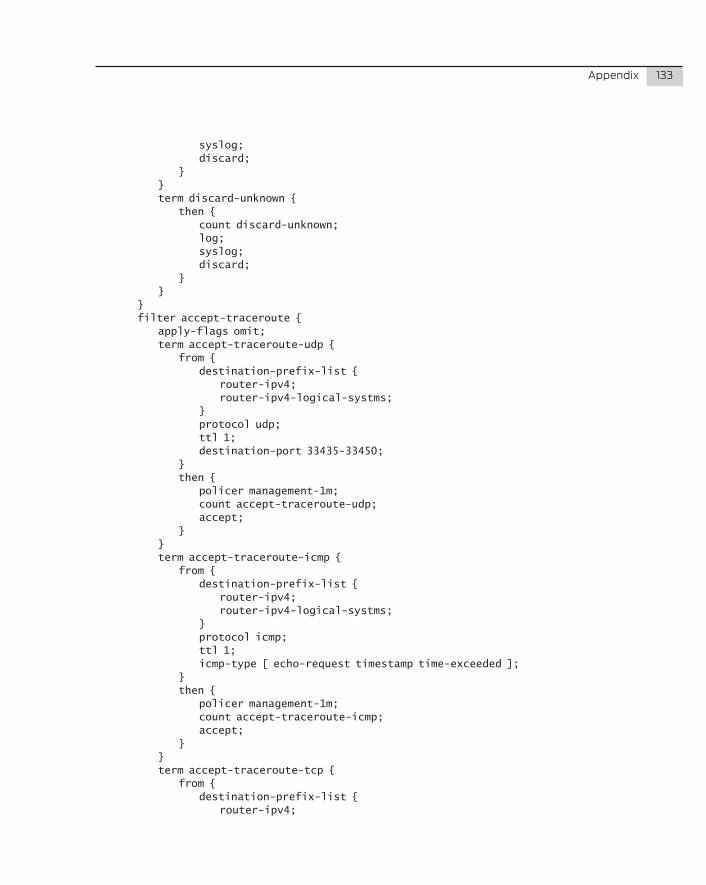
Appendix 133
syslog; discard; } } term discard-unknown { then { count discard-unknown; log; syslog; discard; } } } filter accept-traceroute { apply-flags omit; term accept-traceroute-udp { from { destination-prefix-list { router-ipv4; router-ipv4-logical-systms; } protocol udp; ttl 1; destination-port 33435-33450; } then { policer management-1m; count accept-traceroute-udp; accept; } } term accept-traceroute-icmp { from { destination-prefix-list { router-ipv4; router-ipv4-logical-systms; } protocol icmp; ttl 1; icmp-type [ echo-request timestamp time-exceeded ]; } then { policer management-1m; count accept-traceroute-icmp; accept; } } term accept-traceroute-tcp { from { destination-prefix-list { router-ipv4;
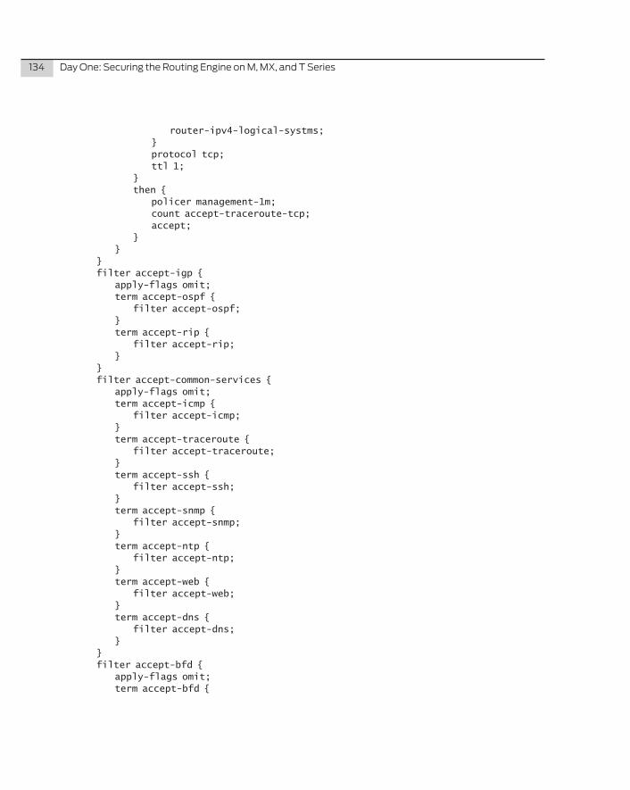
134 DayOne:SecuringtheRoutingEngineonM,MX,andTSeries
router-ipv4-logical-systms; } protocol tcp; ttl 1; } then { policer management-1m; count accept-traceroute-tcp; accept; } } } filter accept-igp { apply-flags omit; term accept-ospf { filter accept-ospf; } term accept-rip { filter accept-rip; } } filter accept-common-services { apply-flags omit; term accept-icmp { filter accept-icmp; } term accept-traceroute { filter accept-traceroute; } term accept-ssh { filter accept-ssh; } term accept-snmp { filter accept-snmp; } term accept-ntp { filter accept-ntp; } term accept-web { filter accept-web; } term accept-dns { filter accept-dns; } } filter accept-bfd { apply-flags omit; term accept-bfd {
Appendix 135
from { source-prefix-list { router-ipv4; router-ipv4-logical-systms; } destination-prefix-list { router-ipv4; router-ipv4-logical-systms; } protocol udp; source-port 49152-65535; destination-port 3784-3785; } then { count accept-bfd; accept; } } } filter accept-ldp { apply-flags omit; term accept-ldp-discover { from { source-prefix-list { router-ipv4; router-ipv4-logical-systms; } destination-prefix-list { multicast-all-routers; } protocol udp; destination-port ldp; } then { count accept-ldp-discover; accept; } } term accept-ldp-unicast { from { source-prefix-list { router-ipv4; router-ipv4-logical-systms; } destination-prefix-list { router-ipv4; router-ipv4-logical-systms; } protocol tcp;
136 DayOne:SecuringtheRoutingEngineonM,MX,andTSeries
port ldp; } then { count accept-ldp-unicast; accept; } } term accept-tldp-discover { from { destination-prefix-list { router-ipv4; router-ipv4-logical-systms; } protocol udp; destination-port ldp; } then { count accept-tldp-discover; accept; } } term accept-ldp-igmp { from { source-prefix-list { router-ipv4; router-ipv4-logical-systms; } destination-prefix-list { multicast-all-routers; } protocol igmp; } then { count accept-ldp-igmp; accept; } } } filter accept-ftp { apply-flags omit; term accept-ftp { from { source-prefix-list { rfc1918; } destination-prefix-list { router-ipv4; router-ipv4-logical-systms; }
Appendix 137
protocol tcp; port [ ftp ftp-data ]; } then { policer management-5m; count accept-ftp; accept; } } } filter accept-rsvp { apply-flags omit; term accept-rsvp { from { destination-prefix-list { router-ipv4; router-ipv4-logical-systms; } protocol rsvp; } then { count accept-rsvp; accept; } } } filter accept-radius { apply-flags omit; term accept-radius { from { source-prefix-list { radius-servers; } destination-prefix-list { router-ipv4; router-ipv4-logical-systms; } protocol udp; source-port [ radacct radius ]; tcp-established; } then { policer management-1m; count accept-radius; accept; } } } filter accept-tacas { apply-flags omit; term accept-tacas {
138 DayOne:SecuringtheRoutingEngineonM,MX,andTSeries
from { source-prefix-list { tacas-servers; } destination-prefix-list { router-ipv4; router-ipv4-logical-systms; } protocol [ tcp udp ]; source-port [ tacacs tacacs-ds ]; tcp-established; } then { policer management-1m; count accept-tacas; accept; } } } filter accept-remote-auth { apply-flags omit; term accept-radius { filter accept-radius; } term accept-tacas { filter accept-tacas; } } filter accept-telnet { apply-flags omit; term accept-telnet { from { source-prefix-list { rfc1918; } destination-prefix-list { router-ipv4; router-ipv4-logical-systms; } protocol tcp; destination-port telnet; } then { policer management-1m; count accept-telnet; accept; } } } filter accept-dns { apply-flags omit;
Appendix 139
term accept-dns { from { source-prefix-list { dns-servers; } destination-prefix-list { router-ipv4; router-ipv4-logical-systms; } protocol udp; source-port 53; } then { policer management-1m; count accept-dns; accept; } } } filter accept-ldp-rsvp { apply-flags omit; term accept-ldp { filter accept-ldp; } term accept-rsvp { filter accept-rsvp; } } filter accept-established { apply-flags omit; term accept-established-tcp-ssh { from { destination-prefix-list { router-ipv4; router-ipv4-logical-systms; } source-port ssh; tcp-established; } then { policer management-5m; count accept-established-tcp-ssh; accept; } } term accept-established-tcp-ftp { from { destination-prefix-list { router-ipv4; router-ipv4-logical-systms; } source-port ftp;
140 DayOne:SecuringtheRoutingEngineonM,MX,andTSeries
tcp-established; } then { policer management-5m; count accept-established-tcp-ftp; accept; } } term accept-established-tcp-ftp-data-syn { from { destination-prefix-list { router-ipv4; router-ipv4-logical-systms; } source-port ftp-data; tcp-initial; } then { policer management-5m; count accept-established-tcp-ftp-data-syn; accept; } } term accept-established-tcp-ftp-data { from { destination-prefix-list { router-ipv4; router-ipv4-logical-systms; } source-port ftp-data; tcp-established; } then { policer management-5m; count accept-established-tcp-ftp-data; accept; } } term accept-established-tcp-telnet { from { destination-prefix-list { router-ipv4; router-ipv4-logical-systms; } source-port telnet; tcp-established; } then { policer management-5m; count accept-established-tcp-telnet; accept;
Appendix 141
} } term accept-established-tcp-fetch { from { destination-prefix-list { router-ipv4; router-ipv4-logical-systms; } source-port [ http https ]; tcp-established; } then { policer management-5m; count accept-established-tcp-fetch; accept; } } term accept-established-udp-ephemeral { from { destination-prefix-list { router-ipv4; router-ipv4-logical-systms; } protocol udp; destination-port 49152-65535; } then { policer management-5m; count accept-established-udp-ephemeral; accept; } } } filter accept-all { apply-flags omit; term accept-all-tcp { from { protocol tcp; } then { count accept-all-tcp; log; syslog; accept; } } term accept-all-udp { from { protocol udp; } then { count accept-all-udp;
142 DayOne:SecuringtheRoutingEngineonM,MX,andTSeries
log; syslog; accept; } } term accept-all-igmp { from { protocol igmp; } then { count accept-all-igmp; log; syslog; accept; } } term accept-icmp { from { protocol icmp; } then { count accept-all-icmp; log; syslog; accept; } } term accept-all-unknown { then { count accept-all-unknown; log; syslog; accept; } } } } policer management-1m { apply-flags omit; if-exceeding { bandwidth-limit 1m; burst-size-limit 625k; } then discard; } policer management-5m { apply-flags omit; if-exceeding { bandwidth-limit 5m; burst-size-limit 625k; }
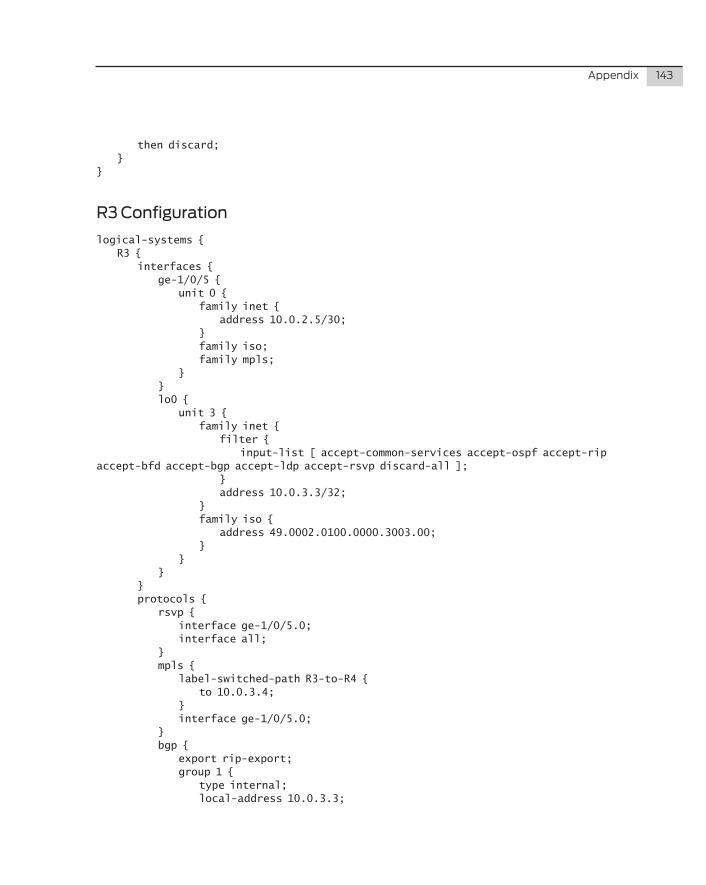
Appendix 143
then discard; }}
R3 Configuration
logical-systems { R3 { interfaces { ge-1/0/5 { unit 0 { family inet { address 10.0.2.5/30; } family iso; family mpls; } } lo0 { unit 3 { family inet { filter { input-list [ accept-common-services accept-ospf accept-rip accept-bfd accept-bgp accept-ldp accept-rsvp discard-all ]; } address 10.0.3.3/32; } family iso { address 49.0002.0100.0000.3003.00; } } } } protocols { rsvp { interface ge-1/0/5.0; interface all; } mpls { label-switched-path R3-to-R4 { to 10.0.3.4; } interface ge-1/0/5.0; } bgp { export rip-export; group 1 { type internal; local-address 10.0.3.3;
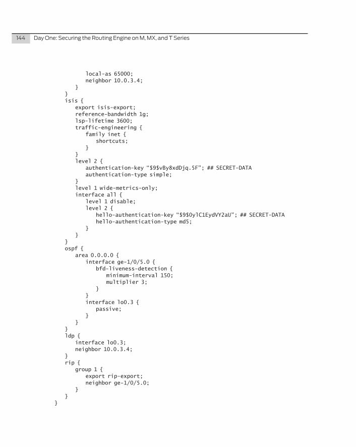
144 DayOne:SecuringtheRoutingEngineonM,MX,andTSeries
local-as 65000; neighbor 10.0.3.4; } } isis { export isis-export; reference-bandwidth 1g; lsp-lifetime 3600; traffic-engineering { family inet { shortcuts; } } level 2 { authentication-key “$9$vBy8xdDjq.5F”; ## SECRET-DATA authentication-type simple; } level 1 wide-metrics-only; interface all { level 1 disable; level 2 { hello-authentication-key “$9$0ylC1EydVY2aU”; ## SECRET-DATA hello-authentication-type md5; } } } ospf { area 0.0.0.0 { interface ge-1/0/5.0 { bfd-liveness-detection { minimum-interval 150; multiplier 3; } } interface lo0.3 { passive; } } } ldp { interface lo0.3; neighbor 10.0.3.4; } rip { group 1 { export rip-export; neighbor ge-1/0/5.0; } } }
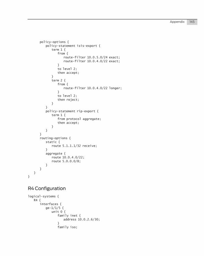
Appendix 145
policy-options { policy-statement isis-export { term 1 { from { route-filter 10.0.5.0/24 exact; route-filter 10.0.4.0/22 exact; } to level 2; then accept; } term 2 { from { route-filter 10.0.4.0/22 longer; } to level 2; then reject; } } policy-statement rip-export { term 1 { from protocol aggregate; then accept; } } } routing-options { static { route 5.1.1.1/32 receive; } aggregate { route 10.0.4.0/22; route 5.0.0.0/8; } } }}
R4 Configuration
logical-systems { R4 { interfaces { ge-1/1/5 { unit 0 { family inet { address 10.0.2.6/30; } family iso;
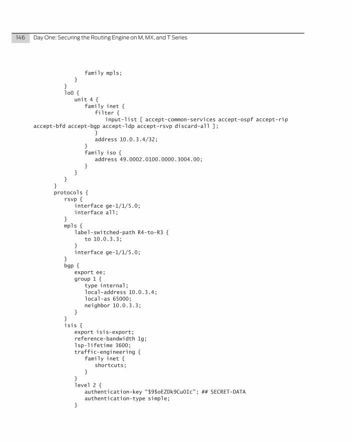
146 DayOne:SecuringtheRoutingEngineonM,MX,andTSeries
family mpls; } } lo0 { unit 4 { family inet { filter { input-list [ accept-common-services accept-ospf accept-rip accept-bfd accept-bgp accept-ldp accept-rsvp discard-all ]; } address 10.0.3.4/32; } family iso { address 49.0002.0100.0000.3004.00; } } } } protocols { rsvp { interface ge-1/1/5.0; interface all; } mpls { label-switched-path R4-to-R3 { to 10.0.3.3; } interface ge-1/1/5.0; } bgp { export ee; group 1 { type internal; local-address 10.0.3.4; local-as 65000; neighbor 10.0.3.3; } } isis { export isis-export; reference-bandwidth 1g; lsp-lifetime 3600; traffic-engineering { family inet { shortcuts; } } level 2 { authentication-key “$9$oEZDk9Cu0Ic”; ## SECRET-DATA authentication-type simple; }
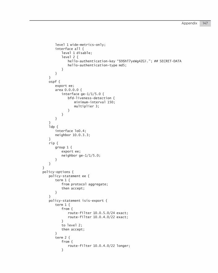
Appendix 147
level 1 wide-metrics-only; interface all { level 1 disable; level 2 { hello-authentication-key “$9$hT7yeWg4ZGi.”; ## SECRET-DATA hello-authentication-type md5; } } } ospf { export ee; area 0.0.0.0 { interface ge-1/1/5.0 { bfd-liveness-detection { minimum-interval 150; multiplier 3; } } } } ldp { interface lo0.4; neighbor 10.0.3.3; } rip { group 1 { export ee; neighbor ge-1/1/5.0; } } } policy-options { policy-statement ee { term 1 { from protocol aggregate; then accept; } } policy-statement isis-export { term 1 { from { route-filter 10.0.5.0/24 exact; route-filter 10.0.4.0/22 exact; } to level 2; then accept; } term 2 { from { route-filter 10.0.4.0/22 longer; }
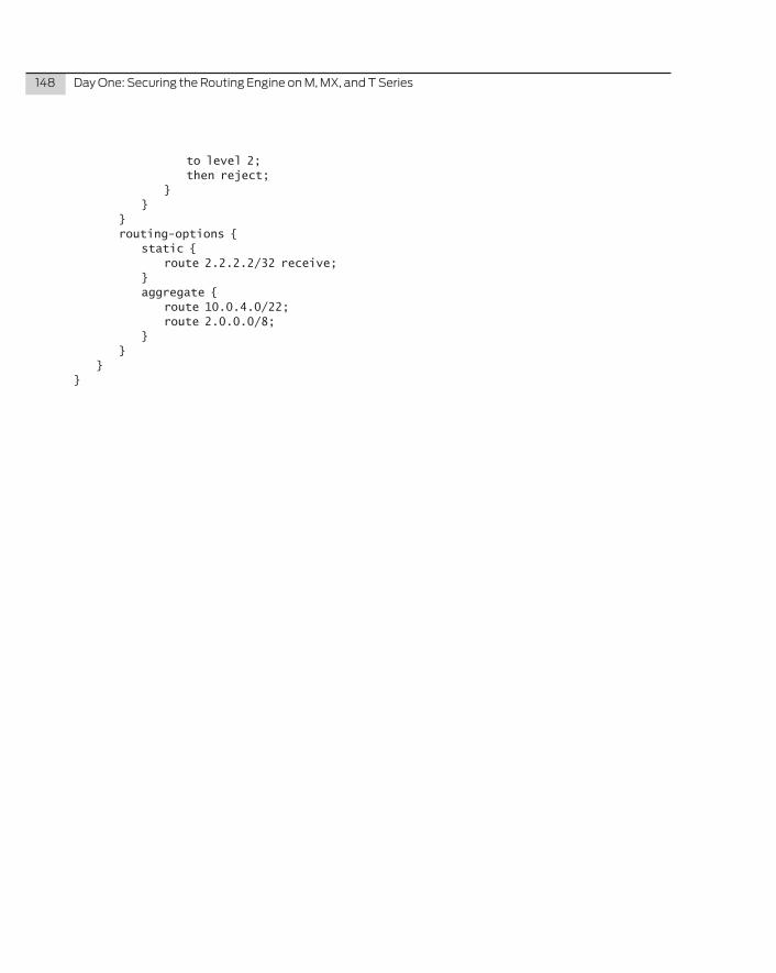
148 DayOne:SecuringtheRoutingEngineonM,MX,andTSeries
to level 2; then reject; } } } routing-options { static { route 2.2.2.2/32 receive; } aggregate { route 10.0.4.0/22; route 2.0.0.0/8; } } }}