day one: migrating eigrp to ospf - politechnika...
TRANSCRIPT
Junos® Networking Technologies Series
Time to take your network to the next
level by moving to open routing stan-
dards? This book charts the migration
path from legacy EIGRP to OSPF step-
by-step. Discover how easy it can be.
By Jack W. Parks, IV
DAY ONE: MIGRATING EIGRP TO OSPF
Juniper Networks Day One books provide just the information you need to know on day one. That’s because they are written by subject matter experts who specialize in getting networks up and running. Visit www.juniper.net/dayone to peruse the complete library.
Published by Juniper Networks Books
DAY ONE: MIGRATING EIGRP TO OSPF
Changing the Interior Gateway Protocol (IGP) on a production network might seem like
a daunting task but good pre-planning and a methodical implementation plan lets it go
smoothly and without incident. This book provides you with the knowledge to make your
migration a success. OSPF is the most ubiquitous IGP in use today by enterprise, gov-
ernment, and education networks because it provides the best blend of knowledgeable
engineers, equipment interoperability, and networking scale. So migrating from EIGRP to
OSPF isn’t a question of why. It’s a question of when.
This book provides a fundamental explanation of the steps required to migrate a net-work from EIGRP to OSPF. You will be able to recreate each of the required steps in a small network with minimal lab equipment.
IT’S DAY ONE AND YOU HAVE A JOB TO DO, SO LEARN HOW TO:
n Understand the fundamental differences between EIGRP and OSPF.
n Use discovery techniques to document routing information and map out the network.
n Evaluate routing policy and its function in the network.
n Verify the proper operation of the IGP.
n Migrate the network IGP from EIGRP to OSPF.
n Add Juniper Networks devices to the existing network.
“EIGRP has been the way that many small to medium networks have done things for years. As
networks grow large, the very characteristics that made EIGRP once attractive begin presenting
hard-to-troubleshoot performance problems. These scaling issues among other challenges even-
tually push network organizations to migrate to the open-standard, much more scalable OSPF.
Jack Parks provides a clear, concise comparison of the two protocols and the guidelines needed
to conduct a migration from EIGRP to OSPF.”
Jeff Doyle, Author, IP Network Consultant, Jeff Doyle and Associates
7100 1333
ISBN 978-1-936779-08-6
9 781936 779086
5 1 4 0 0
7100 1326
Day One: Migrating EIGRP to OSPF
By Jack W. Parks, IV
Chapter 1: Network Preparation . . . . . . . . . . . . . . . . . . . . . . . . . . . . .7
Chapter 2: Network Migration . . . . . . . . . . . . . . . . . . . . . . . . . . . . . 35
Chapter 3: Adding Junos Devices . . . . . . . . . . . . . . . . . . . . . . . . . . .61
Chapter 4: IOS to Junos Comparison . . . . . . . . . . . . . . . . . . . . . . 73
Lessons Learned . . . . . . . . . . . . . . . . . . . . . . . . . . . . . . . . . . . . . . . . . 81
What to Do Next & Where to Go . . . . . . . . . . . . . . . . . . . . . . . . . . . 82
Junos® Networking Technologies Series
© 2011 by Juniper Networks, Inc. All rights reserved.
Juniper Networks, the Juniper Networks logo, Junos, NetScreen, and ScreenOS are registered trademarks of Juniper Networks, Inc. in the United States and other countries. Junose is a trademark of Juniper Networks, Inc. All other trademarks, service marks, registered trademarks, or registered service marks are the property of their respective owners.
Juniper Networks assumes no responsibility for any inaccuracies in this document. Juniper Networks reserves the right to change, modify, transfer, or otherwise revise this publication without notice. Products made or sold by Juniper Networks or components thereof might be covered by one or more of the following patents that are owned by or licensed to Juniper Networks: U.S. Patent Nos. 5,473,599, 5,905,725, 5,909,440, 6,192,051, 6,333,650, 6,359,479, 6,406,312, 6,429,706, 6,459,579, 6,493,347, 6,538,518, 6,538,899, 6,552,918, 6,567,902, 6,578,186, and 6,590,785.
Published by Juniper Networks BooksWriter: Jack W. Parks, IVEditor in Chief: Patrick AmesCopyediting and Proofing: Nancy KoerbelJunos Program Manager: Cathy Gadecki
ISBN: 978-1-936779-08-6 (print)Printed in the USA by Vervante Corporation.
ISBN: 978-1-936779-09-3 (ebook)
Version History: v2 January 2011 3 4 5 6 7 8 9 10 #7100132-en
About the AuthorJack W. Parks IV is a Sr. Systems Engineer with Juniper Networks. He is certified in both Juniper Networks and Cisco as JNCIP-M #991 and CCIE R&S #11685. Jack's industry knowledge spans more than 17 years with 10 years in Service Provider and Enterprise Routing.
Author’s AcknowledgmentsI would like to thank my family for their love, under-standing, and time - you are a precious gift. Many thanks to Eddie Parra for keeping a close eye on the technical aspects and helping expand the content. - JWP
This book is available in a variety of formats at: www.juniper.net/dayone.
Send your suggestions, comments, and critiques by email to [email protected].
Follow the Day One series on Twitter: @Day1Junos
ii
What You Need to Know Before Reading this Book
You should have some experience with the configuration, opera-tion, maintenance of IPv4 networks.
You should have a grasp of IPv4 addressing schemes and the application of IPv4 addressing to interfaces.
You should have an understanding of the Cisco IOS command line interface. Additionally, it is recommended that you have read the Day One books in the Junos Fundamentals Series.
You should understand the purpose of Interior Gateway Protocols in the network.
This book provides a fundamental explanation of the steps required to migrate a network from EIGRP to OSPF. You will be able to recreate each of the required steps in a small network with minimal lab equipment.
After Reading this Book, You’ll Be Able to...
Understand the fundamental differences between EIGRP and OSPF.
Use discovery techniques to document routing information and map out the network.
Evaluate routing policy and its function in the network.
Verify the proper operation of the IGP.
Migrate the network IGP from EIGRP to OSPF.
Add Juniper Networks devices to the existing network.
iii

iv Why Switch from EIGRP to OSPF?
Why Switch from EIGRP to OSPF?
There is a persistent debate over the merits of EIGRP versus OSPF in Cisco network engineering circles. The debate centers on which routing protocol is better suited for an Enterprise network, and both sides have strong arguments based on the capabilities and management of each protocol. The debate is obviously limited to Cisco-only networks and is irrelevant to companies that have deployed multi-vendor networks, but it still begs the question: Why should Cisco-only networks migrate away from EIGRP to a more open protocol like OSPF? Obviously this book takes the OSPF slant, but instead of arguing why it makes the case for why you should. Subtle, but persua-sive nonetheless.
Viewed from the 10,000 foot level, EIGRP limits purchasing decisions by eliminating all competitors. Interoperability is touted and tested by almost every company looking for new networking gear – if existing business practices prevent you from adjusting to market changes and taking advantage of alternate solutions (that save CapEx and OpEx), then it might be time to rethink your vendor strategies. Open stan-dards and open protocols are a good first step towards keeping your vendor choice flexible. Besides, with cloud computing becoming more common and various vendors productizing new equipment and architectures, will vendor lock-in be worth the risk during the next phase of network evolution?
At the 100 foot level, load balancers, content caching devices, WAN acceleration products, and even firewalls have the capability to interconnect and interoperate with the network using open protocols like OSPF for RIP. Networks are complete systems. While as network engineers it is easy to think simply in terms of routers and switches, the scope of the network infrastructure is so much more. Engineers may pave the road, but the network is never the destination.
MORE? A recent Juniper whitepaper, Migrating EIGRP Networks to OSPF, expands on the shortcomings of EIGRP and compliments the OSPF migration strategies in this Day One Book: http://www.juniper.net/us/en/local/pdf/whitepapers/2000365-en.pdf.
Why Switch from EIGRP to OSPF? v
The Rise of MPLS
Whatever level you wish to view this issue from, the propagation of MPLS into the Enterprise, both as an ISP provided service or a home-grown deployment of MPLS VPNs in the network, each has made the requirement to use open standards protocols more prevalent.
For customers who purchase a MPLS L3VPN service from an ISP, the typical PE (Provider Edge) to CE (Customer Edge) routing protocol is either OSPF or BGP. Development work for OSPF has been done specifically for MPLS VPNs. It’s understood that most carriers use a plethora of network equipment vendors (Cisco doesn’t dominate the ISP space like Enterprise) because ISPs must interconnect to their peers and customers, and this can only be achieved with open and agreed upon standards.
MORE? Reference RFC 4577-OSPF as the Provider/Customer Edge Protocol for BGP/MPLS IP Virtual Private Networks (VPNs) to learn about the various options available with OSPF as a PE to CE protocol.
MPLS traffic engineering is another reason companies deploy OSPF, because they need to influence what path traffic takes as it traverses the network regardless of IGP metrics. Through MPLS traffic engineering network architects can create suboptimal paths for low priority traffic overflow, along with optimal paths for high priority traffic such as video. MPLS traffic engineering uses a special database to store specific information about the interfaces such as available bandwidth, the IGP topology, and link coloring information. This specific infor-mation repository is called the Traffic Engineering Database (TED), and the TED requires link-state protocols like OSPF and ISIS to gather the interface information to be used later in the routing process.
Traffic engineering can also be referred to as constraint based routing. Information—such as available bandwidth, the IGP topology, and link coloring information—is used to constrain the path that the MPLS LSPs take to get from point A to point B. With all TE information stored in the TED, and link-state protocols filling the TED with info, you need a link state protocol to do traffic engineering. EIGRP is not a link state protocol, thus EIGRP does not support TE. A protocol like OSPF is required.
vi Why Switch from EIGRP to OSPF?
IP Fast Reroute
Fast failover during routing failures has long been an important feature for today’s networks. EIGRPs feasible successor provided an alternate “back-up” route in the case of a link failure for every destination. Upon detection of a network failure, the router simply installs the successor route as the active route in the route table and service is restored rapidly. Even though routers have become more powerful, OSPF still had to re-run the Dijkstra algorithm before finding an alternate path around the failure.
Loop-Free Alternates (LFA) is fast route for the pure IP play. LFA provides a next-best-path for OSPF and ISIS-learned routes, allowing for convergence times that are more representative of SONET-like failover. Junos supports LFA for OSPF, ISIS, and LDP. As of this writing, Cisco is supporting LFA on IOS-XR for OSPF and ISIS.
MORE? RFC 5286 is the proposed standard for LFA.
Summary
There are deeper, more academic discussions in the EIGRP versus OSPF debate that are left unexplored here. Some might argue we’ve left gaping holes. But this is a Day One book not a “Month Two” tract. This book assumes that showing you how is a better use of your time than telling you why.
This book takes note that everything is pointing to the interconnection of networks – connecting to the cloud, cloud computing, consolidated security. Innovation is in the air. The questions to ask are: Is your current network design preventing the introduction of new technologies that could provide a business edge? Does your network provide choice and flexibility? Is IGP the keystone of your network?
If it’s time to make changes, read on.
Chapter 1
Network Preparation
Understanding OSPF . . . . . . . . . . . . . . . . . . . . . . . . . . . . . 8
Comparing EIGRP and OSPF . . . . . . . . . . . . . . . . . . . . . 14
Migration Strategies . . . . . . . . . . . . . . . . . . . . . . . . . . . . . 19
Document the Network . . . . . . . . . . . . . . . . . . . . . . . . . 24
Summary . . . . . . . . . . . . . . . . . . . . . . . . . . . . . . . . . . . . . . .34
8 Day One: Migrating EIGRP to OSPF
Changing the Interior Gateway Protocol (IGP) on a production network may seem like a daunting task, but good pre-planning and a methodical implementation plan will make the migration go smoothly and without incident. More than likely, your current IGP has been in place since the first router was installed many, many moons ago. While the selected IGP had several benefits over the other IGP offerings of the time, it may no longer be the best IGP option for the network today.
IGP migrations have taken place in the past. Protocols such as RIP (Routing Information Protocol) and IGRP (Interior Gateway Routing Protocol) were once widely deployed in the small IP networks. Their limitations gave way to a new set of IGPs that support more prefixes, allow greater network diameters, and provide quicker convergence times. (RIP and IGRP routing protocols only supported classful networks, a limitation that was the primary reason for mass migra-tions in the 1990s.)
Migrations may occur to support open standards or advanced features like Traffic Engineering (TE). And if you are reading this book, your network is about to undergo a new migration – a migration from EIGRP to OSPF. Relax. We’ll show you how.
Understanding OSPF
OSPF is the most ubiquitous IGP in use by Enterprise networks. Supported by every manufacturing network equipment provider today, OSPF provides the best blend of knowledgeable engineers, equipment interoperability, and networking scale. Almost every trained network engineer, CCNA, JNCIA, etc., has some exposure to the basic theory and operation of OSPF.
MORE? The next couple of sections will cover the basics of OSPF but are by no means a comprehensive guide. Junos Enterprise Routing, by Marschke & Reynolds, O’Reilly Media, has a good primer on OSPF. For more info see www.juniper.net/books.
Some folks don’t know that there are a couple of versions of OSPF. When engineers talk about OSPF, they are actually referring to OSPF version 2 (OSPFv2). The original RFC for OSPFv1 is RFC1131 published in October 1989. RFC1247 updated OSPF to version 2 in July 1991 and the current RFC describing OSPF is RFC2328. There
Chapter 1: Network Preparation 9
have been small updates to OSPF to keep up with changing network trends – like traffic engineering extensions (RFC4203). The takeaway is that OSPF has proven to be adaptable and flexible over the years.
NOTE Along with OSPFv1 and OSPFv2, another version of OSPF was developed to handle IPv6 prefixes throughout the network: OSPFv3. It has similar Junos configuration stanzas as OSPFv2 but it’s contained in the protocols | ospf3 hierarchy under the protocols stanza.
SFP Algorithm
At the heart of OSPF is the SPF – or shortest path first – calculation, which is where OSPF derives most of its name. In 1959 Edsger Dijks-tra created the Dijkstra algorithm, which is responsible for determin-ing the shortest path between two points. This algorithm is used by OSPF and ISIS to calculate the path cost between two prefixes in a network.
All routers in an autonomous system, meaning all routers running OSPF, run SPF calculations to find the best path for every available destination prefix in the network. Each router determines the best path with itself as the root of the SFP tree.
Adjacency Formation
When more than one router running OSPF is connected, and OSPF is enabled on the link shared between the routers, the OSPF routers will form an adjacency. This adjacency is formed and maintained when hello packets are exchanged between the routers. The adjacency is bidirectional in nature and is the foundation for additional protocol communication between the routers.
Hello packets are periodically sent out of the router’s interfaces at specific intervals. The type of interface on which OSPF has been configured determines the hello interval frequency. The type of interface also determines the method by which the routers communi-cate.
There are some common interface network types with OSPF.
n The “broadcast” network dominates the Ethernet everywhere networks of today.
10 Day One: Migrating EIGRP to OSPF
n Frame-Relay and ATM networks are known in OSPF as Non-Broadcast Multi-Access (NBMA) networks – but configured with point-to-point PVCs or DLCIs they become point-to-multipoint networks.
n The point-to-point network type represents true point-to-point circuits, like TDM or SONET.
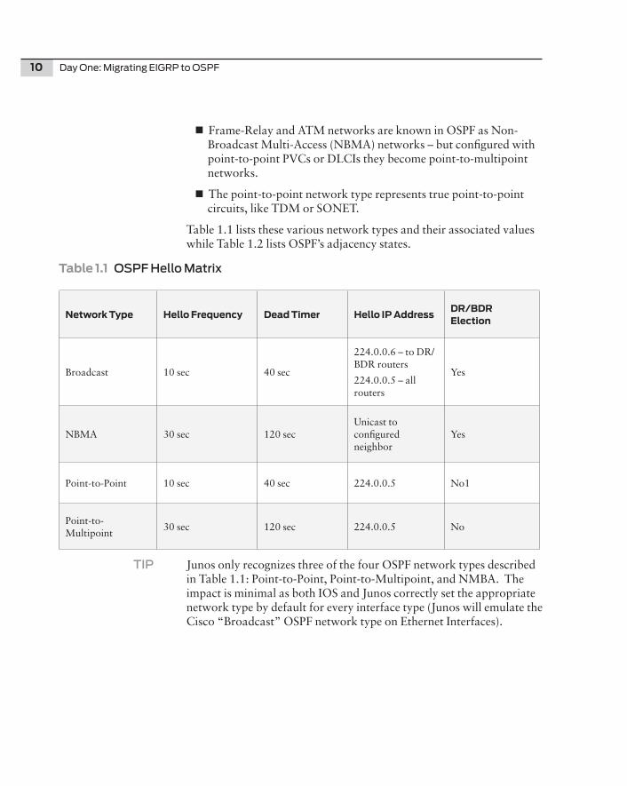
Table 1.1 lists these various network types and their associated values while Table 1.2 lists OSPF’s adjacency states.
Table1.1OSPF Hello Matrix
NetworkType HelloFrequency DeadTimer HelloIPAddressDR/BDRElection
Broadcast 10 sec 40 sec
224.0.0.6 – to DR/BDR routers
224.0.0.5 – all routers
Yes
NBMA 30 sec 120 secUnicast to configured neighbor
Yes
Point-to-Point 10 sec 40 sec 224.0.0.5 No1
Point-to-Multipoint
30 sec 120 sec 224.0.0.5 No
TIP Junos only recognizes three of the four OSPF network types described in Table 1.1: Point-to-Point, Point-to-Multipoint, and NMBA. The impact is minimal as both IOS and Junos correctly set the appropriate network type by default for every interface type (Junos will emulate the Cisco “Broadcast” OSPF network type on Ethernet Interfaces).
Chapter 1: Network Preparation 11
Table1.2OSPF Adjacency States
Neighbor State Description
DownThe beginning state. Hello’s are sent but not received from a neighbor.
AttemptNMBA Only. Hello’s are sent but not received from a neighbor.
InitThe router transitions to this state when a hello packet has been received.
2-WayThe router enters this state when bi-directional communication is occurring with a neighbor.
ExstartThis state represents the beginning and ability to exchange information in the link-state database.
ExchangeIn this state the routers are sharing database descriptor packets.
Loading This is exchange of the actual LSAs.
FullThe final step, both routers have finished exchanging information and are completely adjacent.
Link State Advertisements
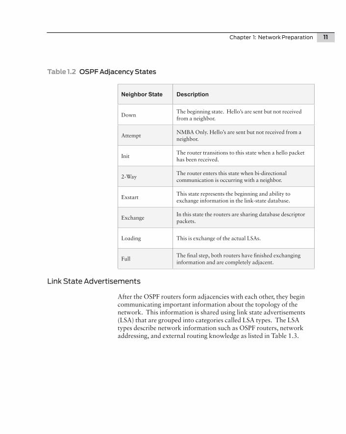
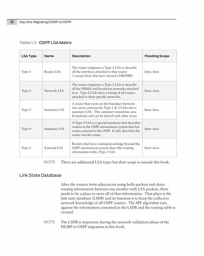
After the OSPF routers form adjacencies with each other, they begin communicating important information about the topology of the network. This information is shared using link state advertisements (LSA) that are grouped into categories called LSA types. The LSA types describe network information such as OSPF routers, network addressing, and external routing knowledge as listed in Table 1.3.
12 Day One: Migrating EIGRP to OSPF
Table1.3OSPF LSA Matrix
LSAType Name Description FloodingScope
Type-1 Router LSAThe router originates a Type-1 LSA to describe all the interfaces attached to that router. (*except those that have elected a DR/DBR)
Intra Area
Type-2 Network LSA
The router originates a Type-2 LSA to describe all the NBMA and broadcast networks attached to it. Type-2 LSAs have a listing of all routers attached to these specific networks.
Intra-Area
Type-3 Summary LSA
A router that exists on the boundary between two areas converts the Type-1 & 2 LSAs into a summary LSA. This summary transitions area boundaries and can be shared with other areas.
Inter-Area
Type-4 Summary LSA
A Type-4 LSA is a special summary that describes routers in the OSPF autonomous system that has routes external to the OSPF. It only describes the router not the routes
Inter-Area
Type-5 External LSARouters that have routing knowledge beyond the OSPF autonomous system share this routing information with a Type-5 LSA
Inter-Area
NOTE There are additional LSA types but their scope is outside this book.
Link State Database
After the routers form adjacencies using hello packets and share routing information between one another with LSA packets, there needs to be a place to store all of that information. That place is the link state database (LSDB) and its function is to keep the collective network knowledge of all OSPF routers. The SPF algorithm runs against the information contained in the LSDB and the routing table is created.
NOTE The LSDB is important during the network validation phase of the EIGRP to OSPF migration in this book.
Chapter 1: Network Preparation 13
Areas
While this book doesn’t demonstrate the use of multiple OSPF areas, understanding how areas help the network scale is important for you to know. Most Enterprise networks only need to use a single area.
Simply stated, OSPF areas are used to partition the network into smaller pieces. Partitioning limits the scope of the routing information contained within each area, which in turn allows OSPF to scale in most massively large networks. (The computing power of routers has grown exponentially over the past few years and Dijkstra is less of a burden on the CPU than was in the past; still, scaling is critical.)
TIP The area number is actually represented in dotted decimal notation, but it is common to use the shorthand representation. Area 0 is actually area 0.0.0.0
There may be situations in Enterprise networks where hub-and-spoke Wide Area Network (WAN) aggregation points could warrant the use of a dedicated area, or areas, to limit the propagation of topology information over low-speed links. (Branch routers and Small Office Home Office (SOHO) routers have limited scaling capacity and minimal computing power.) The spokes on a WAN network are by design a one-way in and out stub network so remote stub networks warrant little more than the propagation of a single default route rather than the entire network topology. But the finite resources of smaller routers, the simplistic topology of remote networks, and the centralized aggregation of branch offices often become prime candi-dates for the use of OSPF areas.
This book uses a single area during the migration. There is a specific rule, however, that must be adhered to when working with multiple OSPF areas: there is but a single backbone area in OSPF and that area is area 0. Multi-area deployments must use area 0 and area 0 may not be segmented in a discontiguous fashion in the network. As the term backbone implies, all other areas must connect to and transit area 0. Two areas may only connect through area 0.
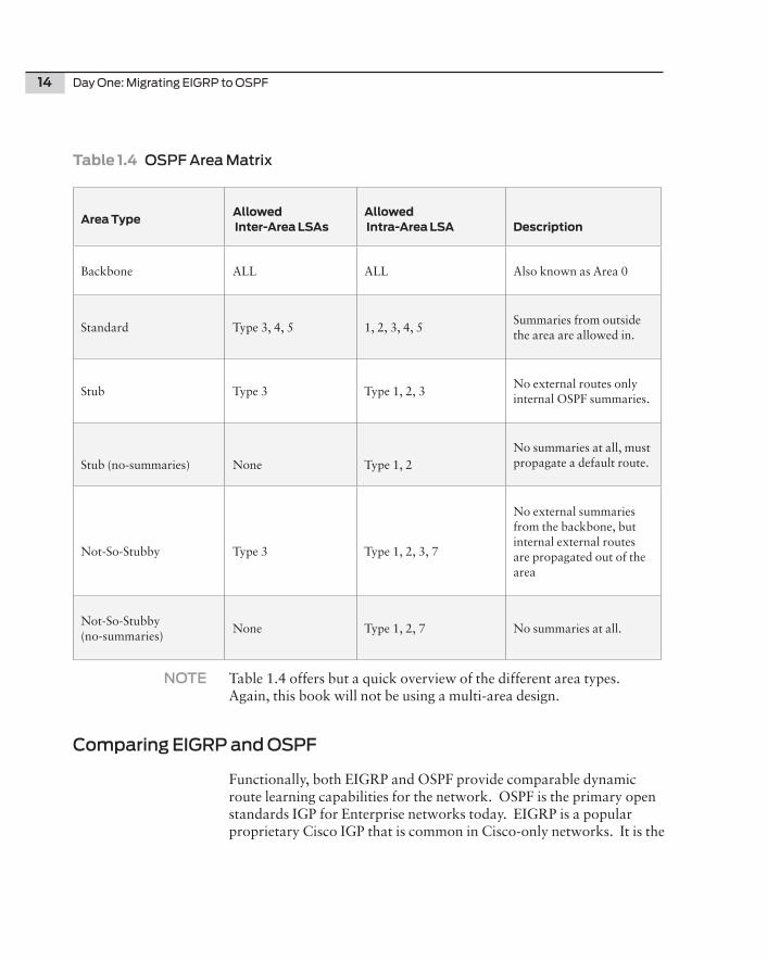
Different Area types to be aware of are also listed in Table 1.4. Differ-ent area types affect the flooding scope of the LSAs and subsequently affect the routing tables of the routes themselves.
14 Day One: Migrating EIGRP to OSPF
Table1.4OSPF Area Matrix
AreaTypeAllowedInter-AreaLSAs
AllowedIntra-AreaLSA Description
Backbone ALL ALL Also known as Area 0
Standard Type 3, 4, 5 1, 2, 3, 4, 5Summaries from outside the area are allowed in.
Stub Type 3 Type 1, 2, 3No external routes only internal OSPF summaries.
Stub (no-summaries) None Type 1, 2No summaries at all, must propagate a default route.
Not-So-Stubby Type 3 Type 1, 2, 3, 7
No external summaries from the backbone, but internal external routes are propagated out of the area
Not-So-Stubby (no-summaries)
None Type 1, 2, 7 No summaries at all.
NOTE Table 1.4 offers but a quick overview of the different area types. Again, this book will not be using a multi-area design.
Comparing EIGRP and OSPF
Functionally, both EIGRP and OSPF provide comparable dynamic route learning capabilities for the network. OSPF is the primary open standards IGP for Enterprise networks today. EIGRP is a popular proprietary Cisco IGP that is common in Cisco-only networks. It is the
Chapter 1: Network Preparation 15
proprietary nature of EIGRP that decreases its business value to the network since integrating best-of-breed or more cost-effective vendors is limited.
NOTE In all fairness, EIGRP is a multiprotocol IGP supporting legacy protocols such as AppleTalk and IPX. Unfortunately, both Novell and Apple now rely on IP as the network transport so the multiprotocol capabilities of EIGRP are more of a liability than a benefit.
Common Characteristics
EIGRP and OSPF share common characteristics with each other even though EIGRP at its core is a Distance Vector protocol and OSPF is a Link-State protocol. Under the covers, each protocol is fundamentally different from the other, but the effect of both protocols is similar for the distribution of routing information throughout the network. This section focuses on the similarities between EIGRP and OSPF in order to bridge your existing understanding of protocol operation while highlighting any significant differences between the two.
NOTE EIGRP has been referred to as a hybrid IGP that contains Distance Vec-tor protocol and Link States protocol properties. This is not accurate. Link State protocols use a topology database to derive reachability information. EIGRP relies on vector calculations to build routing information. Since no topology database exists, EIGRP cannot be or contain Link State information.
Classless Interdomain Routing
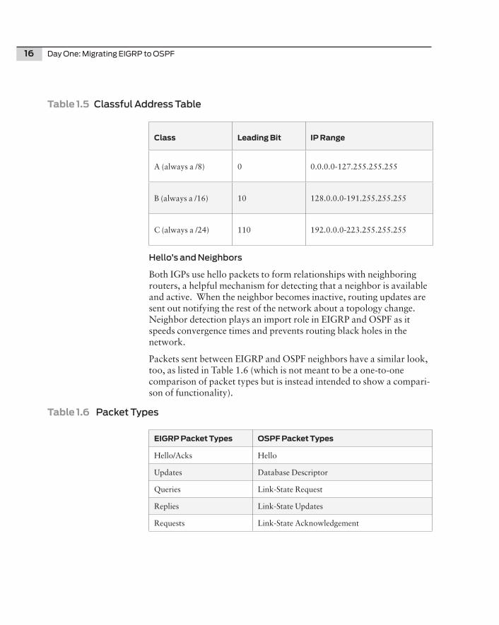
Classless Interdomain Routing (CIDR) is the ability of a routing protocol to support variable length subnet masks (VLSM). Older IGPs did not support this functionality and required the use of classful subnetting on the specific bit boundaries. CIDR is the current method for subnetting and allows prefix lengths like /30, /18, and /15, regard-less of the leading bits of the IP address. Before CIDR, subnetting was fixed and based on the “class” of the IP address range. Because of the fixed prefix length requirement, point-to-point WAN links had to use /24’s at a minimum! Table 1.5, The Classful Address Table, is shown here for a little trip back in history.
16 Day One: Migrating EIGRP to OSPF
Table1.5Classful Address Table
Class LeadingBit IPRange
A (always a /8) 0 0.0.0.0-127.255.255.255
B (always a /16) 10 128.0.0.0-191.255.255.255
C (always a /24) 110 192.0.0.0-223.255.255.255
Hello’s and Neighbors
Both IGPs use hello packets to form relationships with neighboring routers, a helpful mechanism for detecting that a neighbor is available and active. When the neighbor becomes inactive, routing updates are sent out notifying the rest of the network about a topology change. Neighbor detection plays an import role in EIGRP and OSPF as it speeds convergence times and prevents routing black holes in the network.
Packets sent between EIGRP and OSPF neighbors have a similar look, too, as listed in Table 1.6 (which is not meant to be a one-to-one comparison of packet types but is instead intended to show a compari-son of functionality).
Table1.6Packet Types
EIGRPPacketTypes OSPFPacketTypes
Hello/Acks Hello
Updates Database Descriptor
Queries Link-State Request
Replies Link-State Updates
Requests Link-State Acknowledgement
Chapter 1: Network Preparation 17
Path Metrics and Selection
While two different algorithms determine the metric calculation of EIGRP and OSPF, the fact is that they both use a metric to determine a loop free topology and calculate the best path to a particular destina-tion. The interface metric of each path is added to the prefixes cost as the update is propagated across the neighboring routers, which determines the collective metric to that destination.
Concepts such as Equal Cost Multipath (ECMP) are present in both protocols. When two paths to a specific destination have the same cost, then both paths may be used simultaneously in the forwarding of traffic.
Metric and Path Selection Differences
There are major differences between EIGRP and OSPF for determining path cost. First let’s cover EIGRP metrics and path selection, and then we’ll compare OSPF against it.
EIGRP Metric and Path Selection
On the face of things, EIGRP has six different values to determine the overall metric for a given destination.
n Bandwidth
n Load
n Delay
n Reliability
n MTU
n Hop Count
While the breadth of these values seems to be a major benefit to EIGRP for granular control over routing updates, the default metric calcula-tion only uses two of the above values, bandwidth and delay:
metric = bandwidth + delay
MORE? For more info on the metric calculation, see: http://www.cisco.com/en/US/tech/tk365/technologies_white_paper09186a0080094cb7.shtml.
18 Day One: Migrating EIGRP to OSPF
EIGRP path selection uses a concept of the successor and feasible successor and the related concepts of reported distance and feasible distance. Essentially, the successor is the best next-hop router for a given destination. The downstream next-hop router reports the distance to a given destination as the reported distance. The receiving EIGRP router takes the received reported distance and adds its inter-face metric to derive the feasible distance. All of the available paths to a destination are evaluated against each other and the best path is selected. The feasible successor represents the alternate best next-hop router to a given destination.
NOTE EIGRP’s feasible successor route has always been a nice plus for the deployment of EIGRP. The feasible successor route facilitates the fast failover to an alternate path in the event of a primary path failure. RFC5286, Basic Specification for IP Fast Reroute: Loop-Free Alter-nates, defines a method for offering fast failover protection to primary paths in the network. Cisco uses the term IP-FRR. Junos supports Loop Free Alternates on OSPF, ISIS, and LDP.
OSPF Metrics and Path Selection
OSPF uses simple path cost to determine the metric for a given prefix destination. The path cost is calculated from the reference bandwidth divided by the interface bandwidth. The default reference bandwidth is 10^8 which equates to 100Mbits/sec.
TIP In today’s networks, that value is extremely low as every interface above 100Mbps will have a cost of one (1). The reference bandwidth for OSPF should be adjusted for every router in a modern network to a value more than 100Gbits/sec.
And OSPF path selection is pretty simple, since each interface has a cost that is derived through a simple calculation. The lowest cost path is selected as the best path for a given destination, however, there are some concepts that must be taken into consideration when determin-ing the best path, such as OSPF Areas that affect the path selection process.
OSPF selects the path in the following order:
1. IntraArea Routes: Routes that were learned inside the area.
2. InterArea Routes: Routes that were learned from outside the area.
Chapter 1: Network Preparation 19
3. External Routes: Routes that were learned from outside the OSPF autonomous system.
OSPF Areas vs. EIGRP Stubs
There is no concept of areas in EIGRP. EIGRP does have a mechanism to create stub networks that help reduce the resources required on remote routers. This might resemble an OSPF stub area, but the two are not equal, by any means.
This book’s network consists of a single EIGRP AS without stubs and a single area OSPF AS.
Migration Strategies
Now that the basic concepts of EIGRP and OSPF have been covered, let’s discuss migration strategies. There are several common approach-es for migrating a network from one IGP to another, and this book focuses on three models. While these models share common tech-niques, they represent distinct ways to migrate the network. The three migration models are:
n Overlay Model
n Redistribution Model
n Integrated Model
MORE? For the pros and cons to each approach, see www.juniper.net/solu-tions/literature/white_papers/350053.pdf.
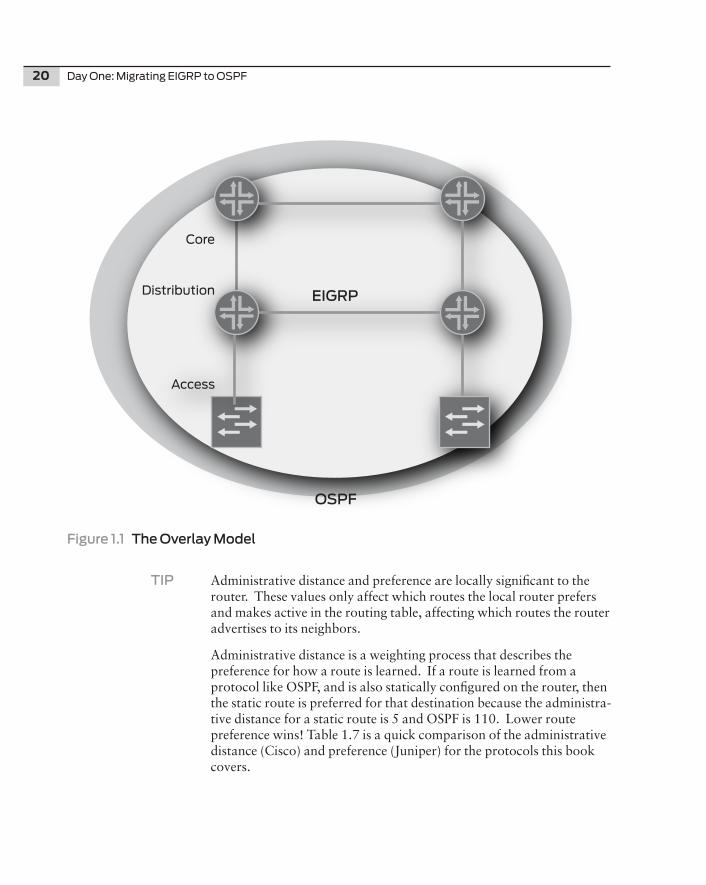
Overlay Model
The overlay model works exactly as its title suggests. EIGRP and OSPF run simultaneously on all routers in the network, and OSPF is essentially overlaid on top of EIGRP, as shown in Figure 1.1. What keeps the protocols separate is the administrative distance values of each protocol. Administrative distance is a Cisco term for describing route preference. (Juniper uses the term preference to describe the same function).
20 Day One: Migrating EIGRP to OSPF
Figure 1.1 The Overlay Model
TIP Administrative distance and preference are locally significant to the router. These values only affect which routes the local router prefers and makes active in the routing table, affecting which routes the router advertises to its neighbors.
Administrative distance is a weighting process that describes the preference for how a route is learned. If a route is learned from a protocol like OSPF, and is also statically configured on the router, then the static route is preferred for that destination because the administra-tive distance for a static route is 5 and OSPF is 110. Lower route preference wins! Table 1.7 is a quick comparison of the administrative distance (Cisco) and preference (Juniper) for the protocols this book covers.
EIGRP
OSPF
Core
Distribution
Access
Chapter 1: Network Preparation 21
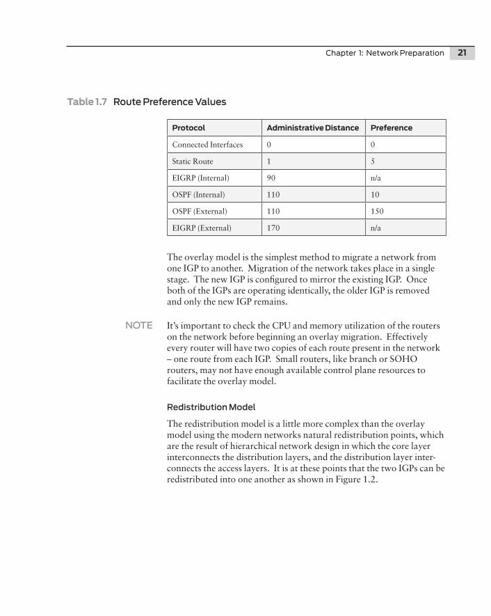
Table1.7Route Preference Values
Protocol AdministrativeDistance Preference
Connected Interfaces 0 0
Static Route 1 5
EIGRP (Internal) 90 n/a
OSPF (Internal) 110 10
OSPF (External) 110 150
EIGRP (External) 170 n/a
The overlay model is the simplest method to migrate a network from one IGP to another. Migration of the network takes place in a single stage. The new IGP is configured to mirror the existing IGP. Once both of the IGPs are operating identically, the older IGP is removed and only the new IGP remains.
NOTE It’s important to check the CPU and memory utilization of the routers on the network before beginning an overlay migration. Effectively every router will have two copies of each route present in the network – one route from each IGP. Small routers, like branch or SOHO routers, may not have enough available control plane resources to facilitate the overlay model.
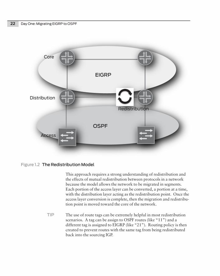
Redistribution Model
The redistribution model is a little more complex than the overlay model using the modern networks natural redistribution points, which are the result of hierarchical network design in which the core layer interconnects the distribution layers, and the distribution layer inter-connects the access layers. It is at these points that the two IGPs can be redistributed into one another as shown in Figure 1.2.
22 Day One: Migrating EIGRP to OSPF
Figure 1.2 The Redistribution Model
This approach requires a strong understanding of redistribution and the effects of mutual redistribution between protocols in a network because the model allows the network to be migrated in segments. Each portion of the access layer can be converted, a portion at a time, with the distribution layer acting as the redistribution point. Once the access layer conversion is complete, then the migration and redistribu-tion point is moved toward the core of the network.
TIP The use of route tags can be extremely helpful in most redistribution scenarios. A tag can be assign to OSPF routes (like “11”) and a different tag is assigned to EIGRP (like “21”). Routing policy is then created to prevent routes with the same tag from being redistributed back into the sourcing IGP.
EIGRP
OSPF
Core
Distribution
Access
Redistribution

Chapter 1: Network Preparation 23
Integrated Model
The integrated model is a hybrid migration model consisting of one part new network build out and one part protocol migration. A new network is purchased and installed in parallel to the legacy network. The core layer of the new network and the legacy network(s) are interconnected. The links between the core routers become the demarcation between both networks and their associated IGPs. Mutual redistribution of routes is performed at the core between the legacy core routers and the new core routers, as shown in Figure 1.3.
Figure 1.3 Integrated Model
Individual sections of the legacy network are migrated to the new core. At the time of migration, the IGP is converted on the relocated section to integrate with the new core. Care must be taken so that the previous IGP routing configuration is removed from the migrated equipment and from the remaining routers in the legacy network or else routing problems, such as blackholes and routing loops, will occur.
EIGRPOSPF
Core
Distribution
Access
Redistribution
24 Day One: Migrating EIGRP to OSPF
Document the Network
Before undertaking a large network change, such as migrating the IGP from EIGRP to OSPF, it is imperative to have an expert understanding of the network topology, IP addressing, and routing policy of the network. Failure to do so will result in outages, routing black holes, and/or an incomplete migration. Now is a good time to update network drawings and IP address assignment records, and to clean up the router’s configurations.
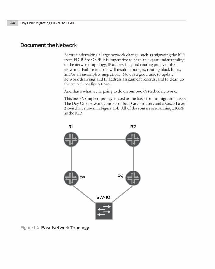
And that’s what we’re going to do on our book’s testbed network.
This book’s simple topology is used as the basis for the migration tasks. The Day One network consists of four Cisco routers and a Cisco Layer 2 switch as shown in Figure 1.4. All of the routers are running EIGRP as the IGP.
Figure 1.4 Base Network Topology
R2R1
R3 R4
SW-10
Chapter 1: Network Preparation 25
IMPORTANT NOTE It is critical that you create working files to assist you in the migration of the network, to have as fall-back files if things go wrong, and to serve as a general paper trail. In this Day One book, tables will represent what are normally your working spreadsheets, figures will represent your Visio drawings, and the router CLI output will be source of all the relevant information.
Interfaces and Adjacencies
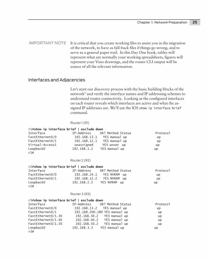
Let’s start our discovery process with the basic building blocks of the networkº and verify the interface names and IP addressing schemes to understand router connectivity. Looking at the configured interfaces on each router reveals which interfaces are active and what the as-signed IP addresses are. We’ll use the IOS show ip interface brief command.
Router 1 (R1)
r1#show ip interface brief | exclude downInterface IP-Address OK? Method Status ProtocolFastEthernet0/0 192.168.13.1 YES manual up up FastEthernet0/1 192.168.12.1 YES manual up up Virtual-Access1 unassigned YES unset up up Loopback0 192.168.1.1 YES manual up up r1#
Router 2 (R2)
r2#show ip interface brief | exclude down Interface IP-Address OK? Method Status ProtocolFastEthernet0/0 192.168.24.1 YES NVRAM up up FastEthernet0/1 192.168.12.2 YES NVRAM up up Loopback0 192.168.2.2 YES NVRAM up up r2#
Router 3 (R3)
r3#show ip interface brief | exclude downInterface IP-Address OK? Method Status ProtocolFastEthernet0/0 192.168.13.2 YES manual up up FastEthernet0/1 192.168.200.180 YES manual up up FastEthernet0/1.30 192.168.30.2 YES manual up up FastEthernet0/1.40 192.168.40.2 YES manual up up FastEthernet0/1.50 192.168.50.2 YES manual up up Loopback0 192.168.3.3 YES manual up up r3#
26 Day One: Migrating EIGRP to OSPF
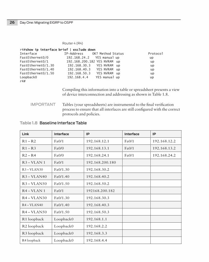
Router 4 (R4)
r4#show ip interface brief | exclude down Interface IP-Address OK? Method Status ProtocolFastEthernet0/0 192.168.24.2 YES manual up up FastEthernet0/1 192.168.200.182 YES NVRAM up up FastEthernet0/1.30 192.168.30.3 YES NVRAM up up FastEthernet0/1.40 192.168.40.3 YES NVRAM up up FastEthernet0/1.50 192.168.50.3 YES NVRAM up up Loopback0 192.168.4.4 YES manual up up r4#
Compiling this information into a table or spreadsheet presents a view of device interconnection and addressing as shown in Table 1.8.
IMPORTANT Tables (your spreadsheets) are instrumental to the final verification process to ensure that all interfaces are still configured with the correct protocols and policies.
Table1.8BaselineInterface Table
Link Interface IP Interface IP
R1 – R2 Fa0/1 192.168.12.1 Fa0/1 192.168.12.2
R1 – R3 Fa0/0 192.168.13.1 Fa0/1 192.168.13.2
R2 – R4 Fa0/0 192.168.24.1 Fa0/1 192.168.24.2
R3 – VLAN 1 Fa0/1 192.168.200.180
R3 – VLAN30 Fa0/1.30 192.168.30.2
R3 – VLAN40 Fa0/1.40 192.168.40.2
R3 – VLAN50 Fa0/1.50 192.168.50.2
R4 – VLAN 1 Fa0/1 192168.200.182
R4 – VLAN30 Fa0/1.30 192.168.30.3
R4 – VLAN40 Fa0/1.40 192.168.40.3
R4 – VLAN50 Fa0/1.50 192.168.50.3
R1 loopback Loopback0 192.168.1.1
R2 loopback Loopback0 192.168.2.2
R3 loopback Loopback0 192.168.3.3
R4 loopback Loopback0 192.168.4.4
Chapter 1: Network Preparation 27
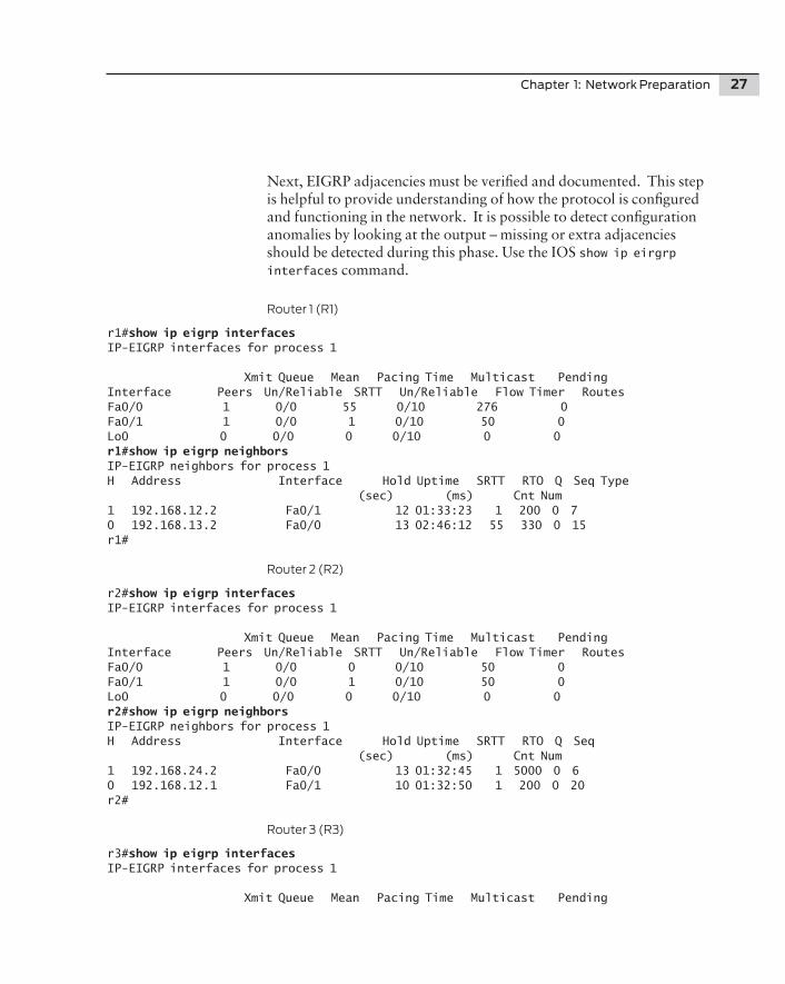
Next, EIGRP adjacencies must be verified and documented. This step is helpful to provide understanding of how the protocol is configured and functioning in the network. It is possible to detect configuration anomalies by looking at the output – missing or extra adjacencies should be detected during this phase. Use the IOS show ip eirgrp interfaces command.
Router 1 (R1)
r1#show ip eigrp interfaces IP-EIGRP interfaces for process 1
Xmit Queue Mean Pacing Time Multicast PendingInterface Peers Un/Reliable SRTT Un/Reliable Flow Timer RoutesFa0/0 1 0/0 55 0/10 276 0Fa0/1 1 0/0 1 0/10 50 0Lo0 0 0/0 0 0/10 0 0r1#show ip eigrp neighbors IP-EIGRP neighbors for process 1H Address Interface Hold Uptime SRTT RTO Q Seq Type (sec) (ms) Cnt Num1 192.168.12.2 Fa0/1 12 01:33:23 1 200 0 7 0 192.168.13.2 Fa0/0 13 02:46:12 55 330 0 15 r1#
Router 2 (R2)
r2#show ip eigrp interfaces IP-EIGRP interfaces for process 1
Xmit Queue Mean Pacing Time Multicast PendingInterface Peers Un/Reliable SRTT Un/Reliable Flow Timer RoutesFa0/0 1 0/0 0 0/10 50 0Fa0/1 1 0/0 1 0/10 50 0Lo0 0 0/0 0 0/10 0 0r2#show ip eigrp neighbors IP-EIGRP neighbors for process 1H Address Interface Hold Uptime SRTT RTO Q Seq (sec) (ms) Cnt Num1 192.168.24.2 Fa0/0 13 01:32:45 1 5000 0 60 192.168.12.1 Fa0/1 10 01:32:50 1 200 0 20r2#
Router 3 (R3)
r3#show ip eigrp interfaces IP-EIGRP interfaces for process 1
Xmit Queue Mean Pacing Time Multicast Pending
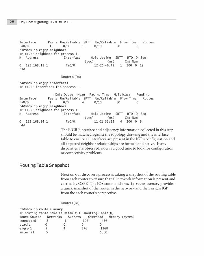
28 Day One: Migrating EIGRP to OSPF
Interface Peers Un/Reliable SRTT Un/Reliable Flow Timer RoutesFa0/0 1 0/0 1 0/10 50 0r3#show ip eigrp neighbors IP-EIGRP neighbors for process 1H Address Interface Hold Uptime SRTT RTO Q Seq (sec) (ms) Cnt Num0 192.168.13.1 Fa0/0 12 02:46:49 1 200 0 19r3#
Router 4 (R4)
r4#show ip eigrp interfaces IP-EIGRP interfaces for process 1
Xmit Queue Mean Pacing Time Multicast PendingInterface Peers Un/Reliable SRTT Un/Reliable Flow Timer RoutesFa0/0 1 0/0 4 0/10 50 0r4#show ip eigrp neighbors IP-EIGRP neighbors for process 1H Address Interface Hold Uptime SRTT RTO Q Seq (sec) (ms) Cnt Num0 192.168.24.1 Fa0/0 11 01:32:15 4 200 0 6r4#
The EIGRP interface and adjacency information collected in this step should be matched against the topology drawing and the interface table to ensure all interfaces are present in the IGP’s configuration and all expected neighbor relationships are formed and active. If any disparities are observed, now is a good time to look for configuration or connectivity problems.
Routing Table Snapshot
Next on our discovery process is taking a snapshot of the routing table from each router to ensure that all network information is present and carried by OSPF. The IOS command show ip route summary provides a quick snapshot of the routes in the network and their origin IGP from the each router’s perspective.
Router 1 (R1)
r1#show ip route summary IP routing table name is Default-IP-Routing-Table(0)Route Source Networks Subnets Overhead Memory (bytes)connected 2 1 192 456static 0 0 0 0eigrp 1 5 4 576 1368internal 5 5860
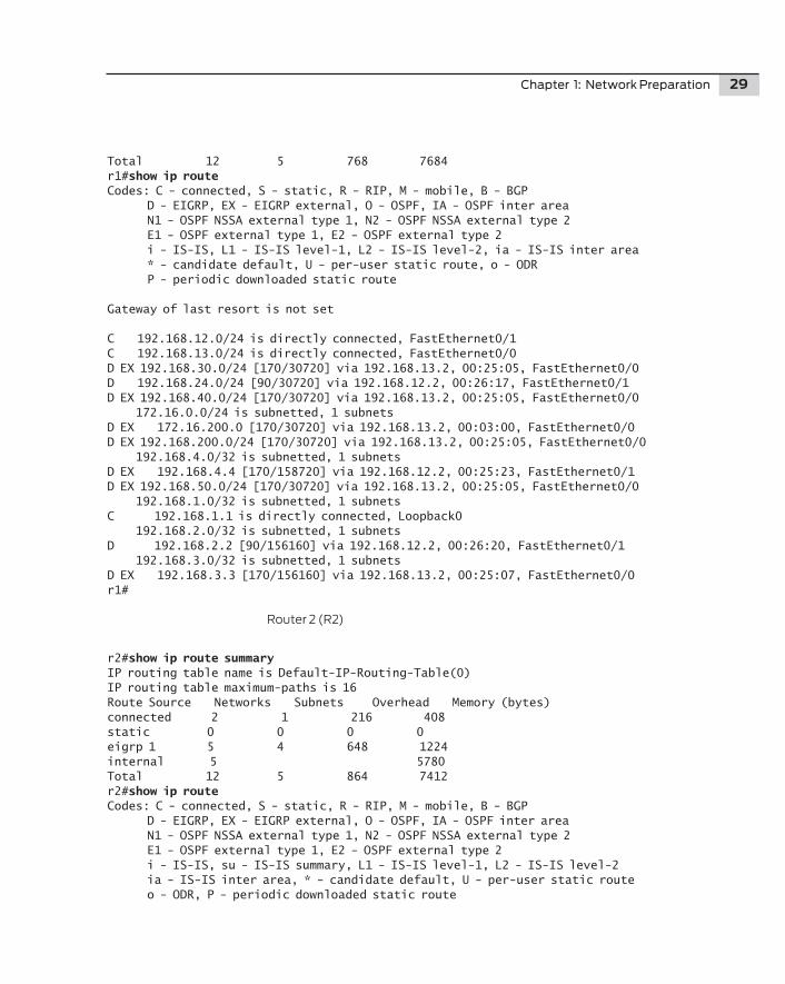
Chapter 1: Network Preparation 29
Total 12 5 768 7684r1#show ip route Codes: C - connected, S - static, R - RIP, M - mobile, B - BGP D - EIGRP, EX - EIGRP external, O - OSPF, IA - OSPF inter area N1 - OSPF NSSA external type 1, N2 - OSPF NSSA external type 2 E1 - OSPF external type 1, E2 - OSPF external type 2 i - IS-IS, L1 - IS-IS level-1, L2 - IS-IS level-2, ia - IS-IS inter area * - candidate default, U - per-user static route, o - ODR P - periodic downloaded static route
Gateway of last resort is not set
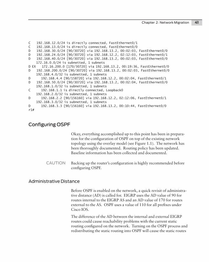
C 192.168.12.0/24 is directly connected, FastEthernet0/1C 192.168.13.0/24 is directly connected, FastEthernet0/0D EX 192.168.30.0/24 [170/30720] via 192.168.13.2, 00:25:05, FastEthernet0/0D 192.168.24.0/24 [90/30720] via 192.168.12.2, 00:26:17, FastEthernet0/1D EX 192.168.40.0/24 [170/30720] via 192.168.13.2, 00:25:05, FastEthernet0/0 172.16.0.0/24 is subnetted, 1 subnetsD EX 172.16.200.0 [170/30720] via 192.168.13.2, 00:03:00, FastEthernet0/0D EX 192.168.200.0/24 [170/30720] via 192.168.13.2, 00:25:05, FastEthernet0/0 192.168.4.0/32 is subnetted, 1 subnetsD EX 192.168.4.4 [170/158720] via 192.168.12.2, 00:25:23, FastEthernet0/1D EX 192.168.50.0/24 [170/30720] via 192.168.13.2, 00:25:05, FastEthernet0/0 192.168.1.0/32 is subnetted, 1 subnetsC 192.168.1.1 is directly connected, Loopback0 192.168.2.0/32 is subnetted, 1 subnetsD 192.168.2.2 [90/156160] via 192.168.12.2, 00:26:20, FastEthernet0/1 192.168.3.0/32 is subnetted, 1 subnetsD EX 192.168.3.3 [170/156160] via 192.168.13.2, 00:25:07, FastEthernet0/0r1#
Router 2 (R2)
r2#show ip route summaryIP routing table name is Default-IP-Routing-Table(0)IP routing table maximum-paths is 16Route Source Networks Subnets Overhead Memory (bytes)connected 2 1 216 408static 0 0 0 0eigrp 1 5 4 648 1224internal 5 5780Total 12 5 864 7412r2#show ip route Codes: C - connected, S - static, R - RIP, M - mobile, B - BGP D - EIGRP, EX - EIGRP external, O - OSPF, IA - OSPF inter area N1 - OSPF NSSA external type 1, N2 - OSPF NSSA external type 2 E1 - OSPF external type 1, E2 - OSPF external type 2 i - IS-IS, su - IS-IS summary, L1 - IS-IS level-1, L2 - IS-IS level-2 ia - IS-IS inter area, * - candidate default, U - per-user static route o - ODR, P - periodic downloaded static route
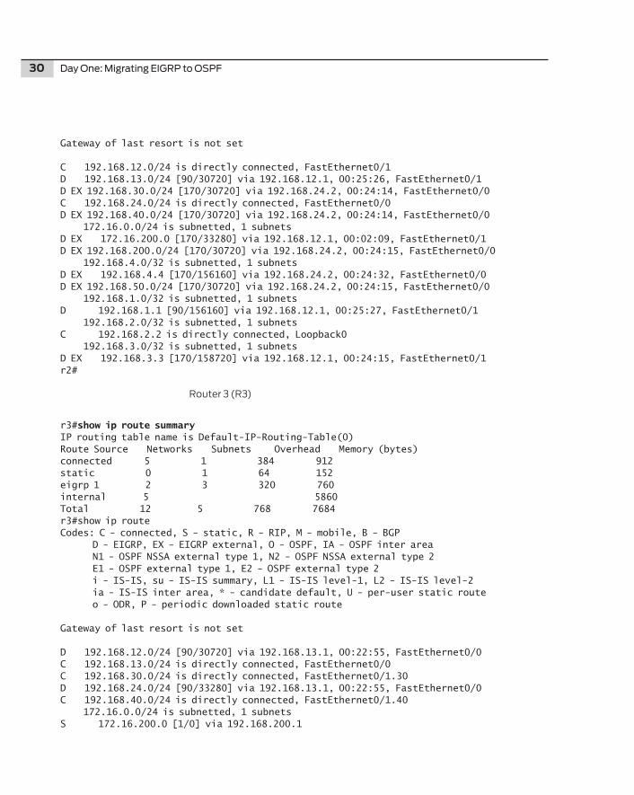
30 Day One: Migrating EIGRP to OSPF
Gateway of last resort is not set
C 192.168.12.0/24 is directly connected, FastEthernet0/1D 192.168.13.0/24 [90/30720] via 192.168.12.1, 00:25:26, FastEthernet0/1D EX 192.168.30.0/24 [170/30720] via 192.168.24.2, 00:24:14, FastEthernet0/0C 192.168.24.0/24 is directly connected, FastEthernet0/0D EX 192.168.40.0/24 [170/30720] via 192.168.24.2, 00:24:14, FastEthernet0/0 172.16.0.0/24 is subnetted, 1 subnetsD EX 172.16.200.0 [170/33280] via 192.168.12.1, 00:02:09, FastEthernet0/1D EX 192.168.200.0/24 [170/30720] via 192.168.24.2, 00:24:15, FastEthernet0/0 192.168.4.0/32 is subnetted, 1 subnetsD EX 192.168.4.4 [170/156160] via 192.168.24.2, 00:24:32, FastEthernet0/0D EX 192.168.50.0/24 [170/30720] via 192.168.24.2, 00:24:15, FastEthernet0/0 192.168.1.0/32 is subnetted, 1 subnetsD 192.168.1.1 [90/156160] via 192.168.12.1, 00:25:27, FastEthernet0/1 192.168.2.0/32 is subnetted, 1 subnetsC 192.168.2.2 is directly connected, Loopback0 192.168.3.0/32 is subnetted, 1 subnetsD EX 192.168.3.3 [170/158720] via 192.168.12.1, 00:24:15, FastEthernet0/1r2#
Router 3 (R3)
r3#show ip route summaryIP routing table name is Default-IP-Routing-Table(0)Route Source Networks Subnets Overhead Memory (bytes)connected 5 1 384 912static 0 1 64 152eigrp 1 2 3 320 760internal 5 5860Total 12 5 768 7684r3#show ip routeCodes: C - connected, S - static, R - RIP, M - mobile, B - BGP D - EIGRP, EX - EIGRP external, O - OSPF, IA - OSPF inter area N1 - OSPF NSSA external type 1, N2 - OSPF NSSA external type 2 E1 - OSPF external type 1, E2 - OSPF external type 2 i - IS-IS, su - IS-IS summary, L1 - IS-IS level-1, L2 - IS-IS level-2 ia - IS-IS inter area, * - candidate default, U - per-user static route o - ODR, P - periodic downloaded static route
Gateway of last resort is not set
D 192.168.12.0/24 [90/30720] via 192.168.13.1, 00:22:55, FastEthernet0/0C 192.168.13.0/24 is directly connected, FastEthernet0/0C 192.168.30.0/24 is directly connected, FastEthernet0/1.30D 192.168.24.0/24 [90/33280] via 192.168.13.1, 00:22:55, FastEthernet0/0C 192.168.40.0/24 is directly connected, FastEthernet0/1.40 172.16.0.0/24 is subnetted, 1 subnetsS 172.16.200.0 [1/0] via 192.168.200.1
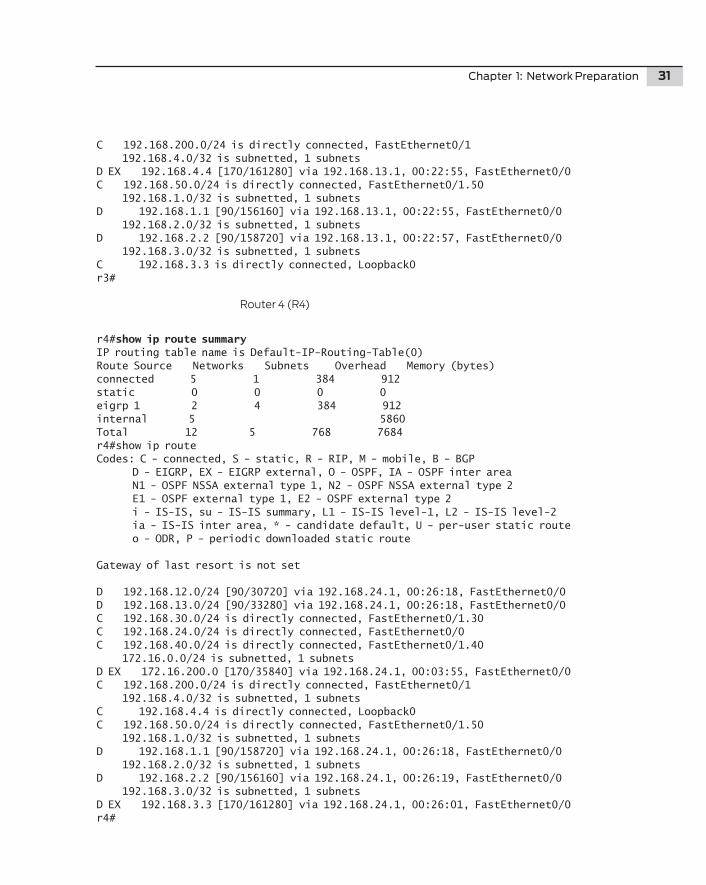
Chapter 1: Network Preparation 31
C 192.168.200.0/24 is directly connected, FastEthernet0/1 192.168.4.0/32 is subnetted, 1 subnetsD EX 192.168.4.4 [170/161280] via 192.168.13.1, 00:22:55, FastEthernet0/0C 192.168.50.0/24 is directly connected, FastEthernet0/1.50 192.168.1.0/32 is subnetted, 1 subnetsD 192.168.1.1 [90/156160] via 192.168.13.1, 00:22:55, FastEthernet0/0 192.168.2.0/32 is subnetted, 1 subnetsD 192.168.2.2 [90/158720] via 192.168.13.1, 00:22:57, FastEthernet0/0 192.168.3.0/32 is subnetted, 1 subnetsC 192.168.3.3 is directly connected, Loopback0r3#
Router 4 (R4)
r4#show ip route summaryIP routing table name is Default-IP-Routing-Table(0)Route Source Networks Subnets Overhead Memory (bytes)connected 5 1 384 912static 0 0 0 0eigrp 1 2 4 384 912internal 5 5860Total 12 5 768 7684r4#show ip route Codes: C - connected, S - static, R - RIP, M - mobile, B - BGP D - EIGRP, EX - EIGRP external, O - OSPF, IA - OSPF inter area N1 - OSPF NSSA external type 1, N2 - OSPF NSSA external type 2 E1 - OSPF external type 1, E2 - OSPF external type 2 i - IS-IS, su - IS-IS summary, L1 - IS-IS level-1, L2 - IS-IS level-2 ia - IS-IS inter area, * - candidate default, U - per-user static route o - ODR, P - periodic downloaded static route
Gateway of last resort is not set
D 192.168.12.0/24 [90/30720] via 192.168.24.1, 00:26:18, FastEthernet0/0D 192.168.13.0/24 [90/33280] via 192.168.24.1, 00:26:18, FastEthernet0/0C 192.168.30.0/24 is directly connected, FastEthernet0/1.30C 192.168.24.0/24 is directly connected, FastEthernet0/0C 192.168.40.0/24 is directly connected, FastEthernet0/1.40 172.16.0.0/24 is subnetted, 1 subnetsD EX 172.16.200.0 [170/35840] via 192.168.24.1, 00:03:55, FastEthernet0/0C 192.168.200.0/24 is directly connected, FastEthernet0/1 192.168.4.0/32 is subnetted, 1 subnetsC 192.168.4.4 is directly connected, Loopback0C 192.168.50.0/24 is directly connected, FastEthernet0/1.50 192.168.1.0/32 is subnetted, 1 subnetsD 192.168.1.1 [90/158720] via 192.168.24.1, 00:26:18, FastEthernet0/0 192.168.2.0/32 is subnetted, 1 subnetsD 192.168.2.2 [90/156160] via 192.168.24.1, 00:26:19, FastEthernet0/0 192.168.3.0/32 is subnetted, 1 subnetsD EX 192.168.3.3 [170/161280] via 192.168.24.1, 00:26:01, FastEthernet0/0r4#
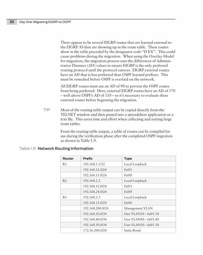
32 Day One: Migrating EIGRP to OSPF
There appear to be several EIGRP routes that are learned external to the EIGRP AS that are showing up in the route table. These routes show in the table preceded by the designator code “D EX”. This could cause problems during the migration. When using the Overlay Model for migration, the migration process uses the differences of Adminis-trative Distance (AD) values to ensure EIGRP is the only preferred routing protocol until the protocol cutover. EIGRP external routes have an AD that is less preferred than OSPF learned prefixes. This must be remedied before OSPF is overlaid on the network.
All EIGRP routes must use an AD of 90 to prevent the OSPF routes from being preferred. Here, external EIGRP routes have an AD of 170 – well above OSPF’s AD of 110 – so it’s necessary to evaluate these external routes before beginning the migration.
TIP Most of the routing table output can be copied directly from the TELNET window and then pasted into a spreadsheet application or a text file. This saves time and effort when collecting and sorting large route tables.
From the routing table output, a table of routes can be compiled for use during the verification phase after the completed OSPF migration as shown in Table 1.9.
Table 1.9 Network Routing Information
Router Prefix Type
R1 192.168.1.1/32 Local Loopback
192.168.12.0/24 Fa0/1
192.168.13.0/24 Fa0/0
R2 192.168.2.2 Local Loopback
192.168.12.0/24 Fa0/1
192.168.24.0/24 Fa0/0
R3 192.168.3.3 Local Loopback
192.168.13.0/24 Fa0/0
192.168.200.0/24 Management VLAN
192.168.30.0/34 User VLAN30 – fa0/1.30
192.168.40.0/34 User VLAN40 – fa0/1.40
192.168.50.0/34 User VLAN50 – fa0/1.50
172.16.200.0/24 Static Route
Chapter 1: Network Preparation 33
R4 192.168.4.4 Local Loopback
192.168.24.0/24 Fa0/0
192.168.200.0/24 Management VLAN
192.168.30.0/34 User VLAN30 – fa0/1.30
192.168.40.0/34 User VLAN40 – fa0/1.40
192.168.50.0/34 User VLAN50 – fa0/1.50
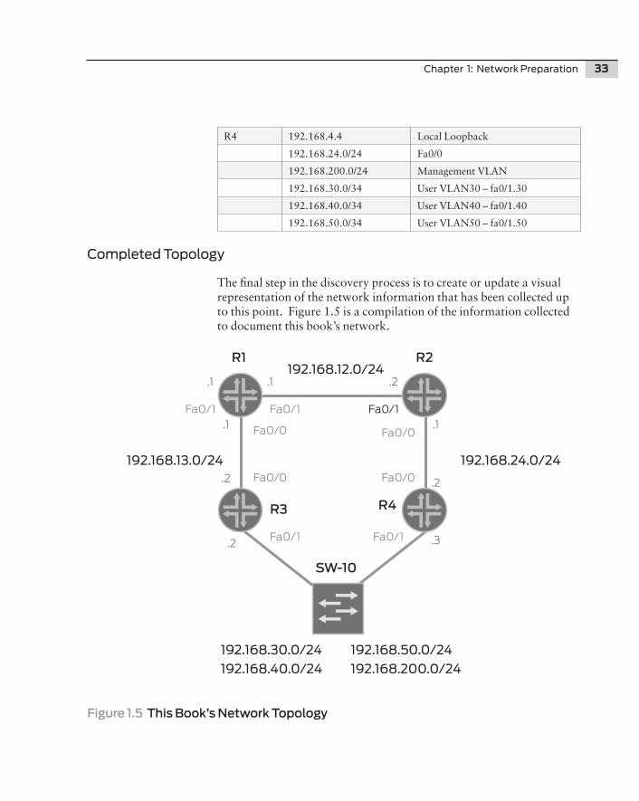
Completed Topology
The final step in the discovery process is to create or update a visual representation of the network information that has been collected up to this point. Figure 1.5 is a compilation of the information collected to document this book’s network.
Figure 1.5 This Book’s Network Topology
R2R1
R3 R4
SW-10
192.168.30.0/24 192.168.50.0/24192.168.40.0/24 192.168.200.0/24
192.168.13.0/24
192.168.12.0/24
192.168.24.0/24
Fa0/1 Fa0/1
Fa0/1Fa0/1
Fa0/1
Fa0/0
Fa0/0
Fa0/0
Fa0/0
.3
.1
.1 .1
.1
.2
.2.2
.2
34 Day One: Migrating EIGRP to OSPF
NOTE While it may seem a bit excessive to collect so much information from such a small network, it’s necessary. The idea here is to discuss the tasks required to migrate a network from EIGRP to OSPF and to stay away from the overload of 1000’s of routes and dozens of routers in the process. Our small-scale lab should demonstrate the migration steps that are critical for more large-scale endeavors; you’ll just have to extrapolate the numbers.
Summary
The systematic discovery of the network will present you with the information necessary to have a successful migration of your network. Each piece of information provides a snapshot of the interface state, IGP configuration, and routing information. Verifying interfaces, updating drawings, and checking route tables provide the necessary insight and comprehension for the actual state of the network. Stale information and poorly implemented policy will only create problems with the protocol migration going forward. The information collected in the discovery phase is critical in the verification process and defines the success criteria for the migration from EIGRP to OSPF.
There can never be too much collected information. This is a case of too much being a good thing!
Chapter 2
Network Migration
Normalizing EIGRP . . . . . . . . . . . . . . . . . . . . . . . . . . . . . 36
Configuring OSPF . . . . . . . . . . . . . . . . . . . . . . . . . . . . . . . 41
Removing EIGRP . . . . . . . . . . . . . . . . . . . . . . . . . . . . . . . 55
Final Verification . . . . . . . . . . . . . . . . . . . . . . . . . . . . . . . . 59
Summary . . . . . . . . . . . . . . . . . . . . . . . . . . . . . . . . . . . . . . 60
36 Day One: Migrating EIGRP to OSPF
This is the chapter of the book where the rubber meets the road. You’ve sat through the concepts of OSPF, endured the brief compari-sons of EIGRP to OSPF, and even watched as the testbed network was verified and documented in its existing state to prepare for the migra-tion.
Now all that’s left is beginning the migration process. It’s day one and we’ve got a job to do.
Normalizing EIGRP
In the discovery phase of our migration process, several routes were observed as being learned externally to the EIGRP autonomous system. The existing configuration of each router’s EIGRP process needs to be evaluated. You’ve probably experienced that over time, router configurations begin to deviate from one another; quick fixes are put in place during troubleshooting sessions, and routing policy evolves to incorporate new or updated best practices. Well, an evalua-tion is required to check for conformity between current network best practices, standard configuration styles, and routing policy before we start the migration.
When looking at the output of IOS operational commands, only the effects of the configuration and routing policy can be seen. So the router’s actual configuration must be reviewed to determine what the routing policy looks like and how the protocols are configured to operate. In this section, each router’s IGP configuration will be evaluated and normalized in preparation for the migration.
NOTE An autonomous system (AS) is simply a collection of network devices under a single realm of control that represents a common and clearly defined routing policy. BGP is a well-known external representation of the autonomous system that uses an actual AS number. The IGP represents the internal portion of the AS. Your autonomous system is your network.
Router 1 (r1) EIGRP Evaluation
r1#show run | begin router eigrprouter eigrp 1 network 192.168.0.0 0.0.255.255 no auto-summary!
Chapter 2: Network Migration 37
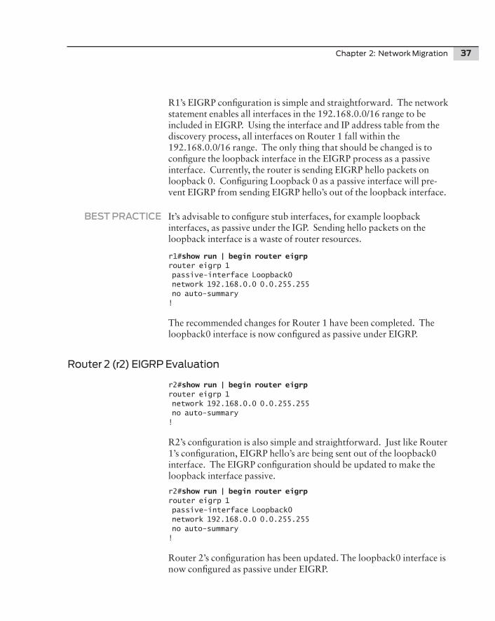
R1’s EIGRP configuration is simple and straightforward. The network statement enables all interfaces in the 192.168.0.0/16 range to be included in EIGRP. Using the interface and IP address table from the discovery process, all interfaces on Router 1 fall within the 192.168.0.0/16 range. The only thing that should be changed is to configure the loopback interface in the EIGRP process as a passive interface. Currently, the router is sending EIGRP hello packets on loopback 0. Configuring Loopback 0 as a passive interface will pre- vent EIGRP from sending EIGRP hello’s out of the loopback interface.
BEST PRACTICE It’s advisable to configure stub interfaces, for example loopback interfaces, as passive under the IGP. Sending hello packets on the loopback interface is a waste of router resources.
r1#show run | begin router eigrprouter eigrp 1 passive-interface Loopback0 network 192.168.0.0 0.0.255.255 no auto-summary!
The recommended changes for Router 1 have been completed. The loopback0 interface is now configured as passive under EIGRP.
Router 2 (r2) EIGRP Evaluation
r2#show run | begin router eigrp router eigrp 1 network 192.168.0.0 0.0.255.255 no auto-summary!
R2’s configuration is also simple and straightforward. Just like Router 1’s configuration, EIGRP hello’s are being sent out of the loopback0 interface. The EIGRP configuration should be updated to make the loopback interface passive.
r2#show run | begin router eigrp router eigrp 1 passive-interface Loopback0 network 192.168.0.0 0.0.255.255 no auto-summary!
Router 2’s configuration has been updated. The loopback0 interface is now configured as passive under EIGRP.
38 Day One: Migrating EIGRP to OSPF
Router 3 (r3) EIGRP Evaluation
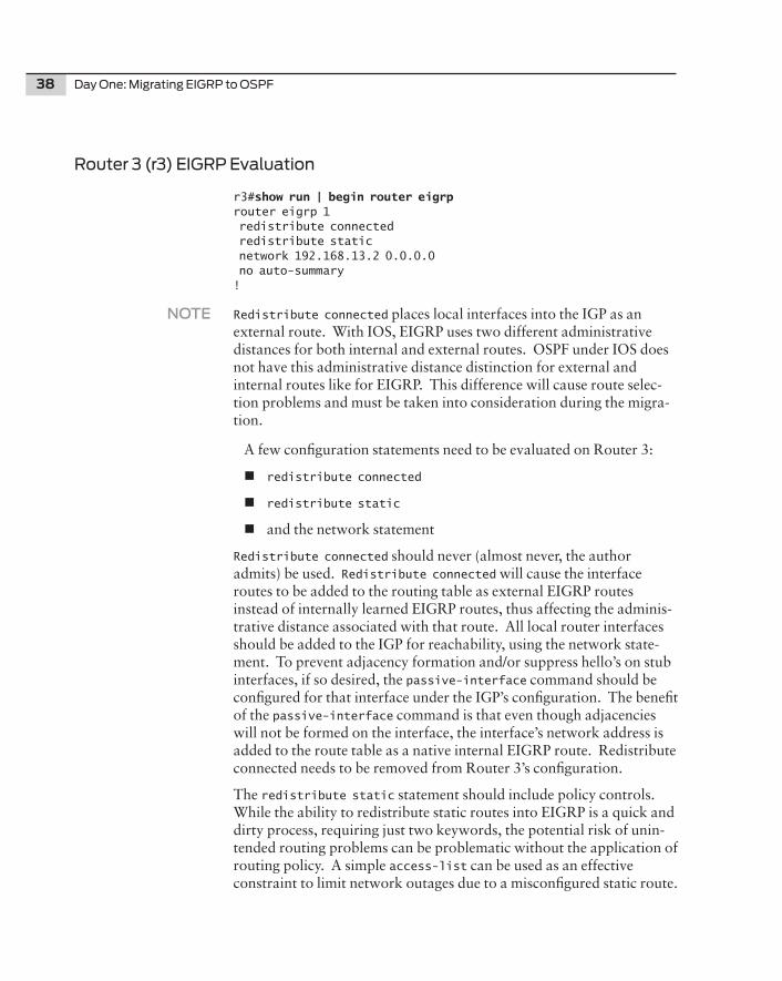
r3#show run | begin router eigrp router eigrp 1 redistribute connected redistribute static network 192.168.13.2 0.0.0.0 no auto-summary!
NOTE Redistribute connected places local interfaces into the IGP as an external route. With IOS, EIGRP uses two different administrative distances for both internal and external routes. OSPF under IOS does not have this administrative distance distinction for external and internal routes like for EIGRP. This difference will cause route selec-tion problems and must be taken into consideration during the migra-tion.
A few configuration statements need to be evaluated on Router 3:
n redistribute connected
n redistribute static
n and the network statement
Redistribute connected should never (almost never, the author admits) be used. Redistribute connected will cause the interface routes to be added to the routing table as external EIGRP routes instead of internally learned EIGRP routes, thus affecting the adminis-trative distance associated with that route. All local router interfaces should be added to the IGP for reachability, using the network state-ment. To prevent adjacency formation and/or suppress hello’s on stub interfaces, if so desired, the passive-interface command should be configured for that interface under the IGP’s configuration. The benefit of the passive-interface command is that even though adjacencies will not be formed on the interface, the interface’s network address is added to the route table as a native internal EIGRP route. Redistribute connected needs to be removed from Router 3’s configuration.
The redistribute static statement should include policy controls. While the ability to redistribute static routes into EIGRP is a quick and dirty process, requiring just two keywords, the potential risk of unin- tended routing problems can be problematic without the application of routing policy. A simple access-list can be used as an effective constraint to limit network outages due to a misconfigured static route.
Chapter 2: Network Migration 39
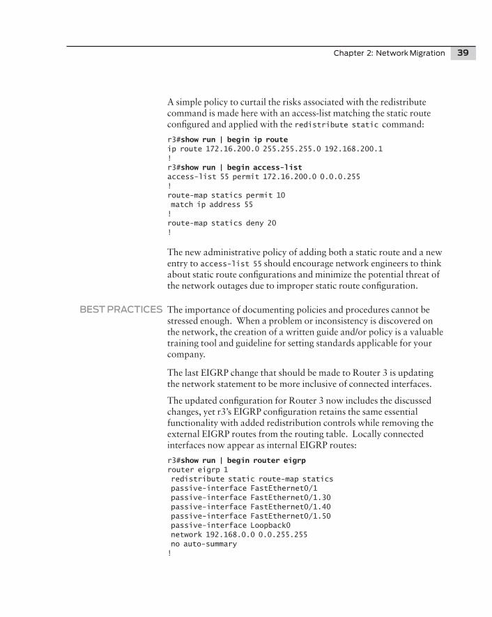
A simple policy to curtail the risks associated with the redistribute command is made here with an access-list matching the static route configured and applied with the redistribute static command:
r3#show run | begin ip route ip route 172.16.200.0 255.255.255.0 192.168.200.1! r3#show run | begin access-listaccess-list 55 permit 172.16.200.0 0.0.0.255!route-map statics permit 10 match ip address 55!route-map statics deny 20!
The new administrative policy of adding both a static route and a new entry to access-list 55 should encourage network engineers to think about static route configurations and minimize the potential threat of the network outages due to improper static route configuration.
BEST PRACTICES The importance of documenting policies and procedures cannot be stressed enough. When a problem or inconsistency is discovered on the network, the creation of a written guide and/or policy is a valuable training tool and guideline for setting standards applicable for your company.
The last EIGRP change that should be made to Router 3 is updating the network statement to be more inclusive of connected interfaces.
The updated configuration for Router 3 now includes the discussed changes, yet r3’s EIGRP configuration retains the same essential functionality with added redistribution controls while removing the external EIGRP routes from the routing table. Locally connected interfaces now appear as internal EIGRP routes:
r3#show run | begin router eigrp router eigrp 1 redistribute static route-map statics passive-interface FastEthernet0/1 passive-interface FastEthernet0/1.30 passive-interface FastEthernet0/1.40 passive-interface FastEthernet0/1.50 passive-interface Loopback0 network 192.168.0.0 0.0.255.255 no auto-summary!
40 Day One: Migrating EIGRP to OSPF
Router 4 (r4) EIGRP Evaluation
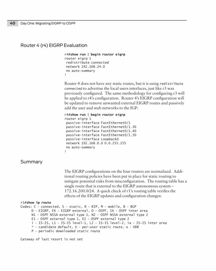
r4#show run | begin router eigrp router eigrp 1 redistribute connected network 192.168.24.0 no auto-summary!
Router 4 does not have any static routes, but it is using redistribute connected to advertise the local users interfaces, just like r3 was previously configured. The same methodology for configuring r3 will be applied to r4’s configuration. Router 4’s EIGRP configuration will be updated to remove unwanted external EIGRP routes and passively add the user and stub networks to the IGP:
r4#show run | begin router eigrp router eigrp 1 passive-interface FastEthernet0/1 passive-interface FastEthernet0/1.30 passive-interface FastEthernet0/1.40 passive-interface FastEthernet0/1.50 passive-interface Loopback0 network 192.168.0.0 0.0.255.255 no auto-summary!
Summary
The EIGRP configurations on the four routers are normalized. Addi-tional routing policies have been put in place for static routing to mitigate potential risks from misconfiguration. The routing table has a single route that is external to the EIGRP autonomous system – 172.16.200.0/24. A quick check of r1’s routing table verifies the effects of the EIGRP updates and configuration changes:
r1#show ip route Codes: C - connected, S - static, R - RIP, M - mobile, B - BGP D - EIGRP, EX - EIGRP external, O - OSPF, IA - OSPF inter area N1 - OSPF NSSA external type 1, N2 - OSPF NSSA external type 2 E1 - OSPF external type 1, E2 - OSPF external type 2 i - IS-IS, L1 - IS-IS level-1, L2 - IS-IS level-2, ia - IS-IS inter area * - candidate default, U - per-user static route, o - ODR P - periodic downloaded static route
Gateway of last resort is not set
Chapter 2: Network Migration 41
C 192.168.12.0/24 is directly connected, FastEthernet0/1C 192.168.13.0/24 is directly connected, FastEthernet0/0D 192.168.30.0/24 [90/30720] via 192.168.13.2, 00:02:03, FastEthernet0/0D 192.168.24.0/24 [90/30720] via 192.168.12.2, 02:12:03, FastEthernet0/1D 192.168.40.0/24 [90/30720] via 192.168.13.2, 00:02:03, FastEthernet0/0 172.16.0.0/24 is subnetted, 1 subnetsD EX 172.16.200.0 [170/30720] via 192.168.13.2, 00:19:36, FastEthernet0/0D 192.168.200.0/24 [90/30720] via 192.168.13.2, 00:02:03, FastEthernet0/0 192.168.4.0/32 is subnetted, 1 subnetsD 192.168.4.4 [90/158720] via 192.168.12.2, 00:02:04, FastEthernet0/1D 192.168.50.0/24 [90/30720] via 192.168.13.2, 00:02:04, FastEthernet0/0 192.168.1.0/32 is subnetted, 1 subnetsC 192.168.1.1 is directly connected, Loopback0 192.168.2.0/32 is subnetted, 1 subnetsD 192.168.2.2 [90/156160] via 192.168.12.2, 02:12:06, FastEthernet0/1 192.168.3.0/32 is subnetted, 1 subnetsD 192.168.3.3 [90/156160] via 192.168.13.2, 00:10:44, FastEthernet0/0r1#
Configuring OSPF
Okay, everything accomplished up to this point has been in prepara-tion for the configuration of OSPF on top of the existing network topology using the overlay model (see Figure 1.1). The network has been thoroughly documented. Routing policy has been updated. Baseline information has been collected and documented.
CAUTION Backing up the router’s configuration is highly recommended before configuring OSPF.
Administrative Distance
Before OSPF is enabled on the network, a quick revisit of administra-tive distance (AD) is called for. EIGRP uses the AD value of 90 for routes internal to the EIGRP AS and an AD value of 170 for routes external to the AS. OSPF uses a value of 110 for all prefixes under Cisco IOS.
The difference of the AD between the internal and external EIGRP routes could cause reachability problems with the current static routing configured on the network. Turning on the OSPF process and redistributing the static routing into OSPF will cause the static routes
42 Day One: Migrating EIGRP to OSPF
to be preferred by OSPF routers. Once the static route is preferred, it becomes the active route and it ceases to be advertised by upstream routers with both EIGRP and OSFP processes enabled.
Once the OSPF process is enabled on the routers, but before the interfaces are configured for adjacencies, the administrative distance for OSPF external routes must be adjusted. The external administra-tive distance for external OSPF routes must be higher than the value for external EIGRP routes at 170. The command distance ospf external 175 under the router’s OSPF process should correct this potential problem:
r1(config)#router ospf 1r1(config-router)#distance ospf ? external External type 5 and type 7 routes inter-area Inter-area routes intra-area Intra-area routes
WARNING Every router in the network must use the distance ospf external command before adding any interfaces to the protocol.
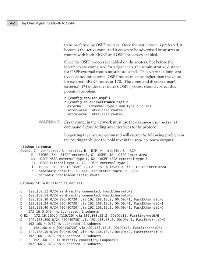
Forgetting the distance command will create the following problem in the routing table (see the bold text in the show ip route output):
r1#show ip route Codes: C - connected, S - static, R - RIP, M - mobile, B - BGP D - EIGRP, EX - EIGRP external, O - OSPF, IA - OSPF inter area N1 - OSPF NSSA external type 1, N2 - OSPF NSSA external type 2 E1 - OSPF external type 1, E2 - OSPF external type 2 i - IS-IS, L1 - IS-IS level-1, L2 - IS-IS level-2, ia - IS-IS inter area * - candidate default, U - per-user static route, o - ODR P - periodic downloaded static route
Gateway of last resort is not set
C 192.168.12.0/24 is directly connected, FastEthernet0/1C 192.168.13.0/24 is directly connected, FastEthernet0/0D 192.168.30.0/24 [90/30720] via 192.168.13.2, 00:09:41, FastEthernet0/0D 192.168.24.0/24 [90/30720] via 192.168.12.2, 00:09:41, FastEthernet0/1D 192.168.40.0/24 [90/30720] via 192.168.13.2, 00:09:41, FastEthernet0/0 172.16.0.0/24 is subnetted, 1 subnetsO E2 172.16.200.0 [110/20] via 192.168.13.2, 00:00:11, FastEthernet0/0D 192.168.200.0/24 [90/30720] via 192.168.13.2, 00:09:41, FastEthernet0/0 192.168.4.0/32 is subnetted, 1 subnetsD 192.168.4.4 [90/158720] via 192.168.12.2, 00:09:42, FastEthernet0/1D 192.168.50.0/24 [90/30720] via 192.168.13.2, 00:09:42, FastEthernet0/0 192.168.1.0/32 is subnetted, 1 subnetsC 192.168.1.1 is directly connected, Loopback0 192.168.2.0/32 is subnetted, 1 subnets

Chapter 2: Network Migration 43
D 192.168.2.2 [90/156160] via 192.168.12.2, 00:09:44, FastEthernet0/1 192.168.3.0/32 is subnetted, 1 subnetsD 192.168.3.3 [90/156160] via 192.168.13.2, 00:09:44, FastEthernet0/0r1#
The 172.16.200.0/24 route is learned via OSPF only and only OSPF enabled routers can reach this destination. EIGRP only routers will not have a route for that destination, thus creating a black hole for this prefix in the network.
Enabling the OSPF Process
Enabling the OSPF process on the routers happens in three phases:
1. The first phase consists of turning on the process and setting the external AD value.
2. Next, the interfaces are added to the OSPF process on each router starting from the core and moving toward the edge of the network.
3. Finally, the policy required to add external routes to OSPF is configured.
CAUTION Cisco IOS activates configuration commands upon a carriage return. So the order of operations is important when configuring Cisco IOS devices.
When enabling the OSPF process, it is recommended to do so starting at the core of the network and moving toward the edge, since the core of the network is responsible for interconnecting all other devices in the network. As more routers are brought online with the OSPF process, the routing information is able to propagate throughout the network to other OSPF speakers.
Phase One
Enable the OSPF process from core to edge and set the external OSPF administrative distance. Explicit configuration of the router-id is recommended to avoid ambiguity in the configuration and to assist in troubleshooting OSPF. The router ID should match the primary loopback IP address of the router (see Table 1.9, Network Routing Information).
44 Day One: Migrating EIGRP to OSPF
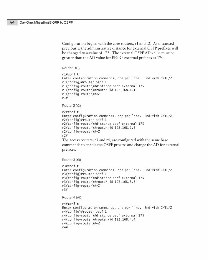
Configuration begins with the core routers, r1 and r2. As discussed previously, the administrative distance for external OSFP prefixes will be changed to a value of 175. The external OSPF AD value must be greater than the AD value for EIGRP external prefixes at 170.
Router 1 (r1)
r1#conf tEnter configuration commands, one per line. End with CNTL/Z.r1(config)#router ospf 1r1(config-router)#distance ospf external 175r1(config-router)#router-id 192.168.1.1r1(config-router)#^Zr1#
Router 2 (r2)
r2#conf tEnter configuration commands, one per line. End with CNTL/Z.r2(config)#router ospf 1r2(config-router)#distance ospf external 175r2(config-router)#router-id 192.168.2.2r2(config-router)#^Zr2#
The access routers, r3 and r4, are configured with the same base commands to enable the OSPF process and change the AD for external prefixes.
Router 3 (r3)
r3#conf tEnter configuration commands, one per line. End with CNTL/Z.r3(config)#router ospf 1r3(config-router)#distance ospf external 175r3(config-router)#router-id 192.168.3.3r3(config-router)#^Zr3#
Router 4 (r4)
r4#conf tEnter configuration commands, one per line. End with CNTL/Z.r4(config)#router ospf 1r4(config-router)#distance ospf external 175r4(config-router)#router-id 192.168.4.4r4(config-router)#^Zr4#
Chapter 2: Network Migration 45
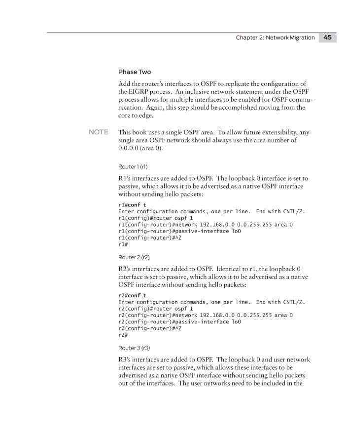
Phase Two
Add the router’s interfaces to OSPF to replicate the configuration of the EIGRP process. An inclusive network statement under the OSPF process allows for multiple interfaces to be enabled for OSPF commu-nication. Again, this step should be accomplished moving from the core to edge.
NOTE This book uses a single OSPF area. To allow future extensibility, any single area OSPF network should always use the area number of 0.0.0.0 (area 0).
Router 1 (r1)
R1’s interfaces are added to OSPF. The loopback 0 interface is set to passive, which allows it to be advertised as a native OSPF interface without sending hello packets:
r1#conf tEnter configuration commands, one per line. End with CNTL/Z.r1(config)#router ospf 1r1(config-router)#network 192.168.0.0 0.0.255.255 area 0r1(config-router)#passive-interface lo0r1(config-router)#^Zr1#
Router 2 (r2)
R2’s interfaces are added to OSPF. Identical to r1, the loopback 0 interface is set to passive, which allows it to be advertised as a native OSPF interface without sending hello packets:
r2#conf tEnter configuration commands, one per line. End with CNTL/Z.r2(config)#router ospf 1r2(config-router)#network 192.168.0.0 0.0.255.255 area 0r2(config-router)#passive-interface lo0r2(config-router)#^Zr2#
Router 3 (r3)
R3’s interfaces are added to OSPF. The loopback 0 and user network interfaces are set to passive, which allows these interfaces to be advertised as a native OSPF interface without sending hello packets out of the interfaces. The user networks need to be included in the
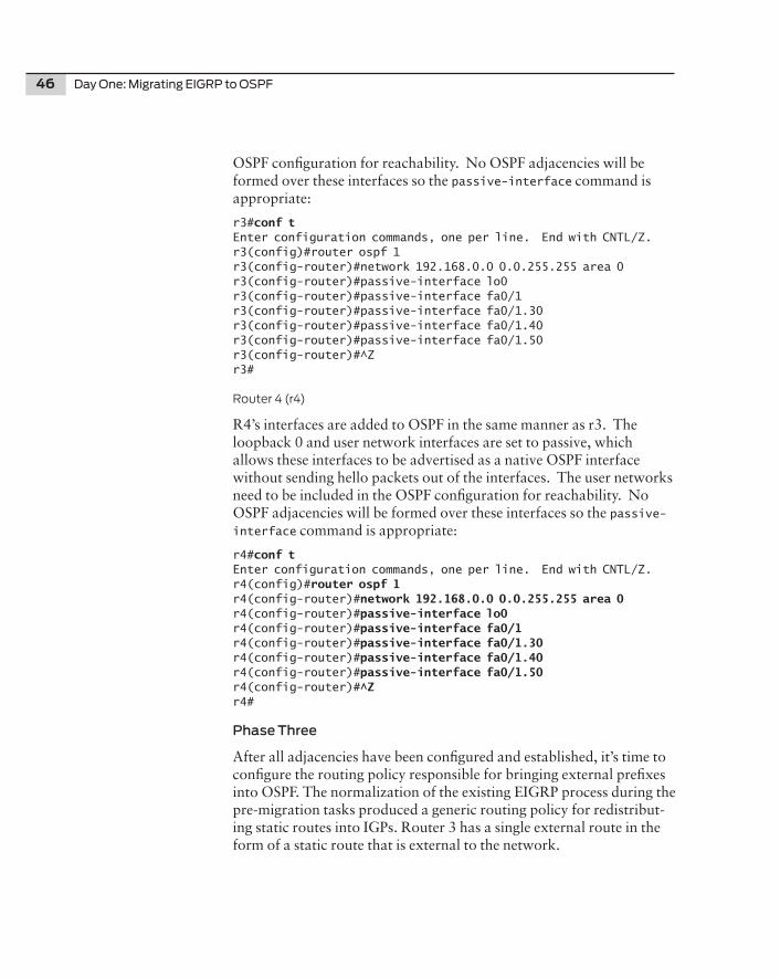
46 Day One: Migrating EIGRP to OSPF
OSPF configuration for reachability. No OSPF adjacencies will be formed over these interfaces so the passive-interface command is appropriate:
r3#conf t Enter configuration commands, one per line. End with CNTL/Z.r3(config)#router ospf 1r3(config-router)#network 192.168.0.0 0.0.255.255 area 0r3(config-router)#passive-interface lo0r3(config-router)#passive-interface fa0/1r3(config-router)#passive-interface fa0/1.30r3(config-router)#passive-interface fa0/1.40r3(config-router)#passive-interface fa0/1.50r3(config-router)#^Zr3#
Router 4 (r4)
R4’s interfaces are added to OSPF in the same manner as r3. The loopback 0 and user network interfaces are set to passive, which allows these interfaces to be advertised as a native OSPF interface without sending hello packets out of the interfaces. The user networks need to be included in the OSPF configuration for reachability. No OSPF adjacencies will be formed over these interfaces so the passive-interface command is appropriate:
r4#conf t Enter configuration commands, one per line. End with CNTL/Z.r4(config)#router ospf 1r4(config-router)#network 192.168.0.0 0.0.255.255 area 0 r4(config-router)#passive-interface lo0r4(config-router)#passive-interface fa0/1r4(config-router)#passive-interface fa0/1.30r4(config-router)#passive-interface fa0/1.40r4(config-router)#passive-interface fa0/1.50r4(config-router)#^Zr4#
Phase Three
After all adjacencies have been configured and established, it’s time to configure the routing policy responsible for bringing external prefixes into OSPF. The normalization of the existing EIGRP process during the pre-migration tasks produced a generic routing policy for redistribut-ing static routes into IGPs. Router 3 has a single external route in the form of a static route that is external to the network.
Chapter 2: Network Migration 47
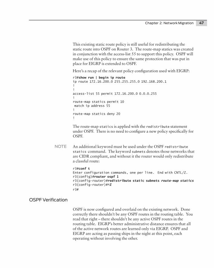
This existing static route policy is still useful for redistributing the static route into OSPF on Router 3. The route-map statics was created in conjunction with the access-list 55 to support this policy. OSPF will make use of this policy to ensure the same protection that was put in place for EIGRP is extended to OSPF.
Here’s a recap of the relevant policy configuration used with EIGRP:
r3#show run | begin ip route ip route 172.16.200.0 255.255.255.0 192.168.200.1!!access-list 55 permit 172.16.200.0 0.0.0.255!route-map statics permit 10 match ip address 55!route-map statics deny 20!
The route-map statics is applied with the redistribute statement under OSPF. There is no need to configure a new policy specifically for OSPF.
NOTE An additional keyword must be used under the OSPF redistribute statics command. The keyword subnets denotes those networks that are CIDR compliant, and without it the router would only redistribute a classful route:
r3#conf tEnter configuration commands, one per line. End with CNTL/Z.r3(config)#router ospf 1r3(config-router)#redistribute static subnets route-map statics r3(config-router)#^Z
r3#
OSPF Verification
OSPF is now configured and overlaid on the existing network. Done correctly there shouldn’t be any OSPF routes in the routing table. You read that right – there shouldn’t be any active OSPF routes in the routing table. EIGRP’s better administrative distance ensures that all of the active network routes are learned only via EIGRP. OSPF and EIGRP are acting as passing ships in the night at this point, each operating without involving the other.
48 Day One: Migrating EIGRP to OSPF
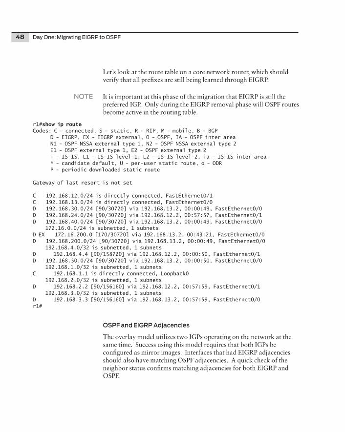
Let’s look at the route table on a core network router, which should verify that all prefixes are still being learned through EIGRP.
NOTE It is important at this phase of the migration that EIGRP is still the preferred IGP. Only during the EIGRP removal phase will OSPF routes become active in the routing table.
r1#show ip route Codes: C - connected, S - static, R - RIP, M - mobile, B - BGP D - EIGRP, EX - EIGRP external, O - OSPF, IA - OSPF inter area N1 - OSPF NSSA external type 1, N2 - OSPF NSSA external type 2 E1 - OSPF external type 1, E2 - OSPF external type 2 i - IS-IS, L1 - IS-IS level-1, L2 - IS-IS level-2, ia - IS-IS inter area * - candidate default, U - per-user static route, o - ODR P - periodic downloaded static route
Gateway of last resort is not set
C 192.168.12.0/24 is directly connected, FastEthernet0/1C 192.168.13.0/24 is directly connected, FastEthernet0/0D 192.168.30.0/24 [90/30720] via 192.168.13.2, 00:00:49, FastEthernet0/0D 192.168.24.0/24 [90/30720] via 192.168.12.2, 00:57:57, FastEthernet0/1D 192.168.40.0/24 [90/30720] via 192.168.13.2, 00:00:49, FastEthernet0/0 172.16.0.0/24 is subnetted, 1 subnetsD EX 172.16.200.0 [170/30720] via 192.168.13.2, 00:43:21, FastEthernet0/0D 192.168.200.0/24 [90/30720] via 192.168.13.2, 00:00:49, FastEthernet0/0 192.168.4.0/32 is subnetted, 1 subnetsD 192.168.4.4 [90/158720] via 192.168.12.2, 00:00:50, FastEthernet0/1D 192.168.50.0/24 [90/30720] via 192.168.13.2, 00:00:50, FastEthernet0/0 192.168.1.0/32 is subnetted, 1 subnetsC 192.168.1.1 is directly connected, Loopback0 192.168.2.0/32 is subnetted, 1 subnetsD 192.168.2.2 [90/156160] via 192.168.12.2, 00:57:59, FastEthernet0/1 192.168.3.0/32 is subnetted, 1 subnetsD 192.168.3.3 [90/156160] via 192.168.13.2, 00:57:59, FastEthernet0/0r1#
OSPF and EIGRP Adjacencies
The overlay model utilizes two IGPs operating on the network at the same time. Success using this model requires that both IGPs be configured as mirror images. Interfaces that had EIGRP adjacencies should also have matching OSPF adjacencies. A quick check of the neighbor status confirms matching adjacencies for both EIGRP and OSPF.
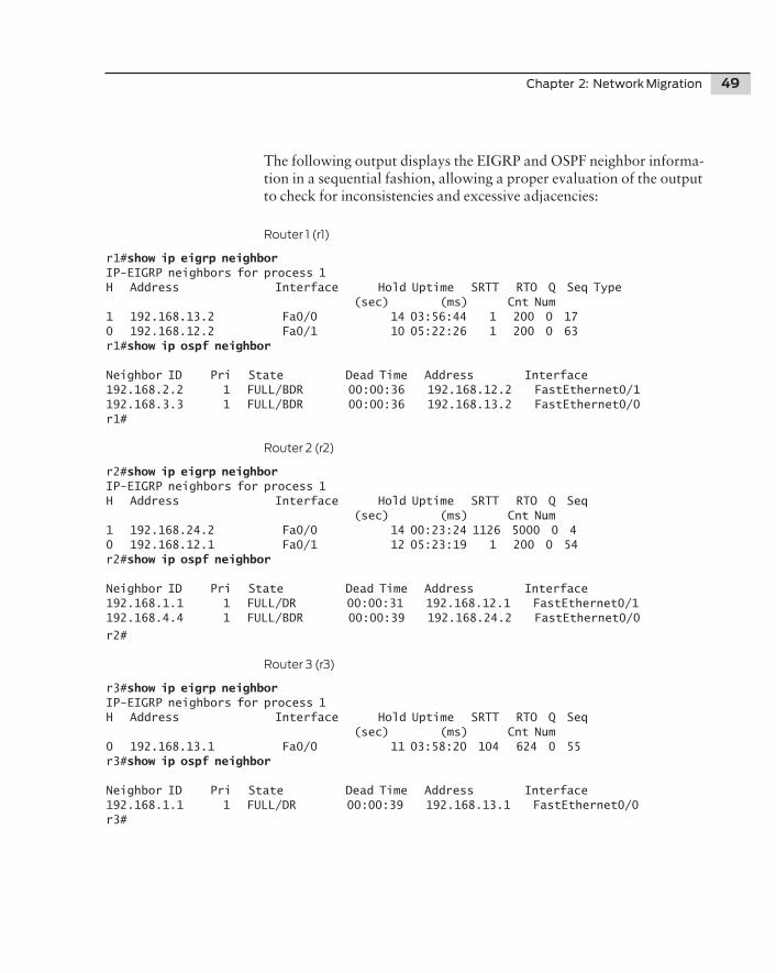
Chapter 2: Network Migration 49
The following output displays the EIGRP and OSPF neighbor informa-tion in a sequential fashion, allowing a proper evaluation of the output to check for inconsistencies and excessive adjacencies:
Router 1 (r1)
r1#show ip eigrp neighborIP-EIGRP neighbors for process 1H Address Interface Hold Uptime SRTT RTO Q Seq Type (sec) (ms) Cnt Num1 192.168.13.2 Fa0/0 14 03:56:44 1 200 0 170 192.168.12.2 Fa0/1 10 05:22:26 1 200 0 63r1#show ip ospf neighbor
Neighbor ID Pri State Dead Time Address Interface192.168.2.2 1 FULL/BDR 00:00:36 192.168.12.2 FastEthernet0/1192.168.3.3 1 FULL/BDR 00:00:36 192.168.13.2 FastEthernet0/0r1#
Router 2 (r2)
r2#show ip eigrp neighborIP-EIGRP neighbors for process 1H Address Interface Hold Uptime SRTT RTO Q Seq (sec) (ms) Cnt Num1 192.168.24.2 Fa0/0 14 00:23:24 1126 5000 0 40 192.168.12.1 Fa0/1 12 05:23:19 1 200 0 54r2#show ip ospf neighbor
Neighbor ID Pri State Dead Time Address Interface192.168.1.1 1 FULL/DR 00:00:31 192.168.12.1 FastEthernet0/1192.168.4.4 1 FULL/BDR 00:00:39 192.168.24.2 FastEthernet0/0
r2#
Router 3 (r3)
r3#show ip eigrp neighbor IP-EIGRP neighbors for process 1H Address Interface Hold Uptime SRTT RTO Q Seq (sec) (ms) Cnt Num0 192.168.13.1 Fa0/0 11 03:58:20 104 624 0 55r3#show ip ospf neighbor
Neighbor ID Pri State Dead Time Address Interface192.168.1.1 1 FULL/DR 00:00:39 192.168.13.1 FastEthernet0/0r3#
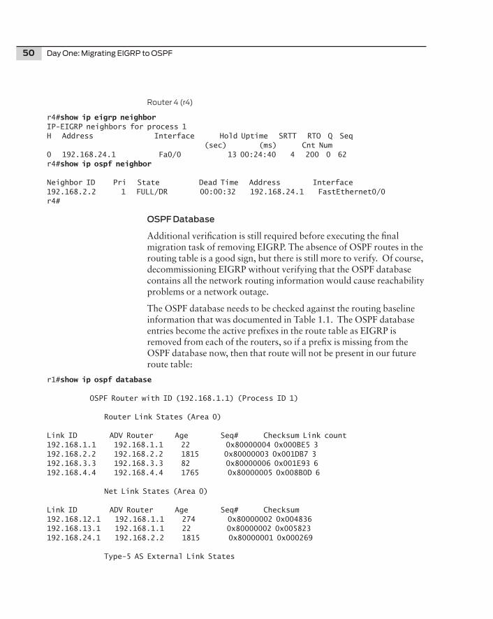
50 Day One: Migrating EIGRP to OSPF
Router 4 (r4)
r4#show ip eigrp neighborIP-EIGRP neighbors for process 1H Address Interface Hold Uptime SRTT RTO Q Seq (sec) (ms) Cnt Num0 192.168.24.1 Fa0/0 13 00:24:40 4 200 0 62r4#show ip ospf neighbor
Neighbor ID Pri State Dead Time Address Interface192.168.2.2 1 FULL/DR 00:00:32 192.168.24.1 FastEthernet0/0r4#
OSPF Database
Additional verification is still required before executing the final migration task of removing EIGRP. The absence of OSPF routes in the routing table is a good sign, but there is still more to verify. Of course, decommissioning EIGRP without verifying that the OSPF database contains all the network routing information would cause reachability problems or a network outage.
The OSPF database needs to be checked against the routing baseline information that was documented in Table 1.1. The OSPF database entries become the active prefixes in the route table as EIGRP is removed from each of the routers, so if a prefix is missing from the OSPF database now, then that route will not be present in our future route table:
r1#show ip ospf database
OSPF Router with ID (192.168.1.1) (Process ID 1)
Router Link States (Area 0)
Link ID ADV Router Age Seq# Checksum Link count192.168.1.1 192.168.1.1 22 0x80000004 0x000BE5 3192.168.2.2 192.168.2.2 1815 0x80000003 0x001DB7 3192.168.3.3 192.168.3.3 82 0x80000006 0x001E93 6192.168.4.4 192.168.4.4 1765 0x80000005 0x008B0D 6
Net Link States (Area 0)
Link ID ADV Router Age Seq# Checksum192.168.12.1 192.168.1.1 274 0x80000002 0x004836192.168.13.1 192.168.1.1 22 0x80000002 0x005823192.168.24.1 192.168.2.2 1815 0x80000001 0x000269
Type-5 AS External Link States
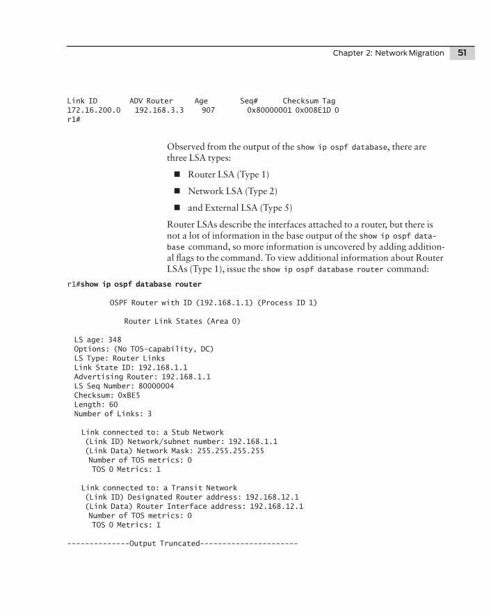
Chapter 2: Network Migration 51
Link ID ADV Router Age Seq# Checksum Tag172.16.200.0 192.168.3.3 907 0x80000001 0x008E1D 0r1#
Observed from the output of the show ip ospf database, there are three LSA types:
n Router LSA (Type 1)
n Network LSA (Type 2)
n and External LSA (Type 5)
Router LSAs describe the interfaces attached to a router, but there is not a lot of information in the base output of the show ip ospf data-base command, so more information is uncovered by adding addition-al flags to the command. To view additional information about Router LSAs (Type 1), issue the show ip ospf database router command:
r1#show ip ospf database router
OSPF Router with ID (192.168.1.1) (Process ID 1)
Router Link States (Area 0)
LS age: 348 Options: (No TOS-capability, DC) LS Type: Router Links Link State ID: 192.168.1.1 Advertising Router: 192.168.1.1 LS Seq Number: 80000004 Checksum: 0xBE5 Length: 60 Number of Links: 3
Link connected to: a Stub Network (Link ID) Network/subnet number: 192.168.1.1 (Link Data) Network Mask: 255.255.255.255 Number of TOS metrics: 0 TOS 0 Metrics: 1
Link connected to: a Transit Network (Link ID) Designated Router address: 192.168.12.1 (Link Data) Router Interface address: 192.168.12.1 Number of TOS metrics: 0 TOS 0 Metrics: 1
--------------Output Truncated----------------------
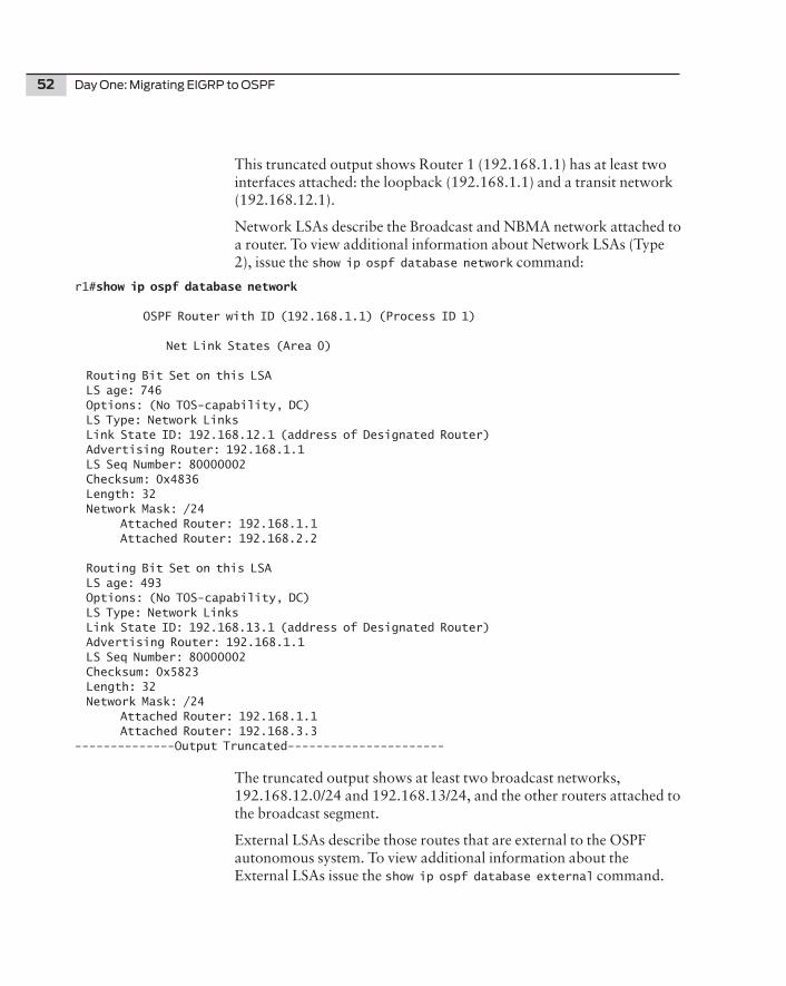
52 Day One: Migrating EIGRP to OSPF
This truncated output shows Router 1 (192.168.1.1) has at least two interfaces attached: the loopback (192.168.1.1) and a transit network (192.168.12.1).
Network LSAs describe the Broadcast and NBMA network attached to a router. To view additional information about Network LSAs (Type 2), issue the show ip ospf database network command:
r1#show ip ospf database network
OSPF Router with ID (192.168.1.1) (Process ID 1)
Net Link States (Area 0)
Routing Bit Set on this LSA LS age: 746 Options: (No TOS-capability, DC) LS Type: Network Links Link State ID: 192.168.12.1 (address of Designated Router) Advertising Router: 192.168.1.1 LS Seq Number: 80000002 Checksum: 0x4836 Length: 32 Network Mask: /24 Attached Router: 192.168.1.1 Attached Router: 192.168.2.2
Routing Bit Set on this LSA LS age: 493 Options: (No TOS-capability, DC) LS Type: Network Links Link State ID: 192.168.13.1 (address of Designated Router) Advertising Router: 192.168.1.1 LS Seq Number: 80000002 Checksum: 0x5823 Length: 32 Network Mask: /24 Attached Router: 192.168.1.1 Attached Router: 192.168.3.3--------------Output Truncated----------------------
The truncated output shows at least two broadcast networks, 192.168.12.0/24 and 192.168.13/24, and the other routers attached to the broadcast segment.
External LSAs describe those routes that are external to the OSPF autonomous system. To view additional information about the External LSAs issue the show ip ospf database external command.
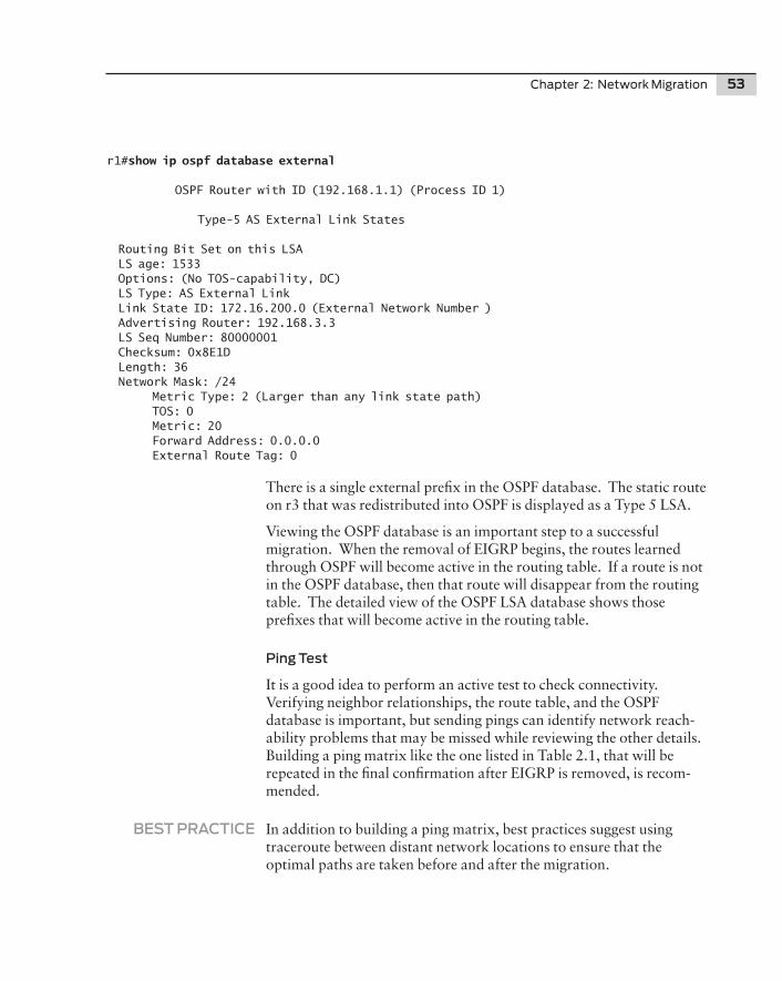
Chapter 2: Network Migration 53
r1#show ip ospf database external
OSPF Router with ID (192.168.1.1) (Process ID 1)
Type-5 AS External Link States
Routing Bit Set on this LSA LS age: 1533 Options: (No TOS-capability, DC) LS Type: AS External Link Link State ID: 172.16.200.0 (External Network Number ) Advertising Router: 192.168.3.3 LS Seq Number: 80000001 Checksum: 0x8E1D Length: 36 Network Mask: /24 Metric Type: 2 (Larger than any link state path) TOS: 0 Metric: 20 Forward Address: 0.0.0.0 External Route Tag: 0
There is a single external prefix in the OSPF database. The static route on r3 that was redistributed into OSPF is displayed as a Type 5 LSA.
Viewing the OSPF database is an important step to a successful migration. When the removal of EIGRP begins, the routes learned through OSPF will become active in the routing table. If a route is not in the OSPF database, then that route will disappear from the routing table. The detailed view of the OSPF LSA database shows those prefixes that will become active in the routing table.
Ping Test
It is a good idea to perform an active test to check connectivity. Verifying neighbor relationships, the route table, and the OSPF database is important, but sending pings can identify network reach-ability problems that may be missed while reviewing the other details. Building a ping matrix like the one listed in Table 2.1, that will be repeated in the final confirmation after EIGRP is removed, is recom-mended.
BEST PRACTICE In addition to building a ping matrix, best practices suggest using traceroute between distant network locations to ensure that the optimal paths are taken before and after the migration.
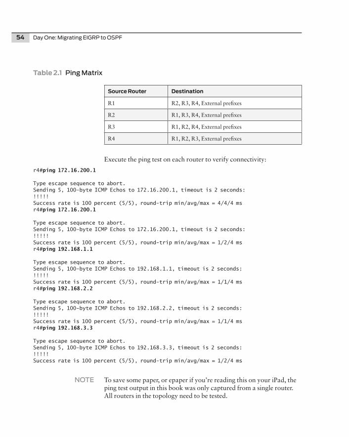
54 Day One: Migrating EIGRP to OSPF
Table2.1Ping Matrix
SourceRouter Destination
R1 R2, R3, R4, External prefixes
R2 R1, R3, R4, External prefixes
R3 R1, R2, R4, External prefixes
R4 R1, R2, R3, External prefixes
Execute the ping test on each router to verify connectivity:
r4#ping 172.16.200.1
Type escape sequence to abort.Sending 5, 100-byte ICMP Echos to 172.16.200.1, timeout is 2 seconds:!!!!!Success rate is 100 percent (5/5), round-trip min/avg/max = 4/4/4 msr4#ping 172.16.200.1
Type escape sequence to abort.Sending 5, 100-byte ICMP Echos to 172.16.200.1, timeout is 2 seconds:!!!!!Success rate is 100 percent (5/5), round-trip min/avg/max = 1/2/4 msr4#ping 192.168.1.1
Type escape sequence to abort.Sending 5, 100-byte ICMP Echos to 192.168.1.1, timeout is 2 seconds:!!!!!Success rate is 100 percent (5/5), round-trip min/avg/max = 1/1/4 msr4#ping 192.168.2.2
Type escape sequence to abort.Sending 5, 100-byte ICMP Echos to 192.168.2.2, timeout is 2 seconds:!!!!!Success rate is 100 percent (5/5), round-trip min/avg/max = 1/1/4 msr4#ping 192.168.3.3
Type escape sequence to abort.Sending 5, 100-byte ICMP Echos to 192.168.3.3, timeout is 2 seconds:!!!!!Success rate is 100 percent (5/5), round-trip min/avg/max = 1/2/4 ms
NOTE To save some paper, or epaper if you’re reading this on your iPad, the ping test output in this book was only captured from a single router. All routers in the topology need to be tested.
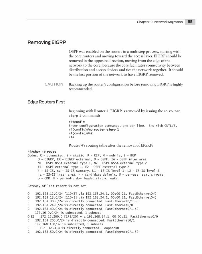
Chapter 2: Network Migration 55
Removing EIGRP
OSPF was enabled on the routers in a multistep process, starting with the core routers and moving toward the access layer. EIGRP should be removed in the opposite direction, moving from the edge of the network to the core, because the core facilitates connectivity between distribution and access devices and ties the network together. It should be the last portion of the network to have EIGRP removed.
CAUTION Backing up the router’s configuration before removing EIGRP is highly recommended.
Edge Routers First
Beginning with Router 4, EIGRP is removed by issuing the no router eigrp 1 command:
r4#conf tEnter configuration commands, one per line. End with CNTL/Z.r4(config)#no router eigrp 1r4(config)#^Zr4#
Router 4’s routing table after the removal of EIGRP:
r4#show ip routeCodes: C - connected, S - static, R - RIP, M - mobile, B - BGP D - EIGRP, EX - EIGRP external, O - OSPF, IA - OSPF inter area N1 - OSPF NSSA external type 1, N2 - OSPF NSSA external type 2 E1 - OSPF external type 1, E2 - OSPF external type 2 i - IS-IS, su - IS-IS summary, L1 - IS-IS level-1, L2 - IS-IS level-2 ia - IS-IS inter area, * - candidate default, U - per-user static route o - ODR, P - periodic downloaded static route
Gateway of last resort is not set
O 192.168.12.0/24 [110/2] via 192.168.24.1, 00:00:21, FastEthernet0/0O 192.168.13.0/24 [110/3] via 192.168.24.1, 00:00:21, FastEthernet0/0C 192.168.30.0/24 is directly connected, FastEthernet0/1.30C 192.168.24.0/24 is directly connected, FastEthernet0/0C 192.168.40.0/24 is directly connected, FastEthernet0/1.40 172.16.0.0/24 is subnetted, 1 subnetsO E2 172.16.200.0 [175/20] via 192.168.24.1, 00:00:21, FastEthernet0/0C 192.168.200.0/24 is directly connected, FastEthernet0/1 192.168.4.0/32 is subnetted, 1 subnetsC 192.168.4.4 is directly connected, Loopback0C 192.168.50.0/24 is directly connected, FastEthernet0/1.50
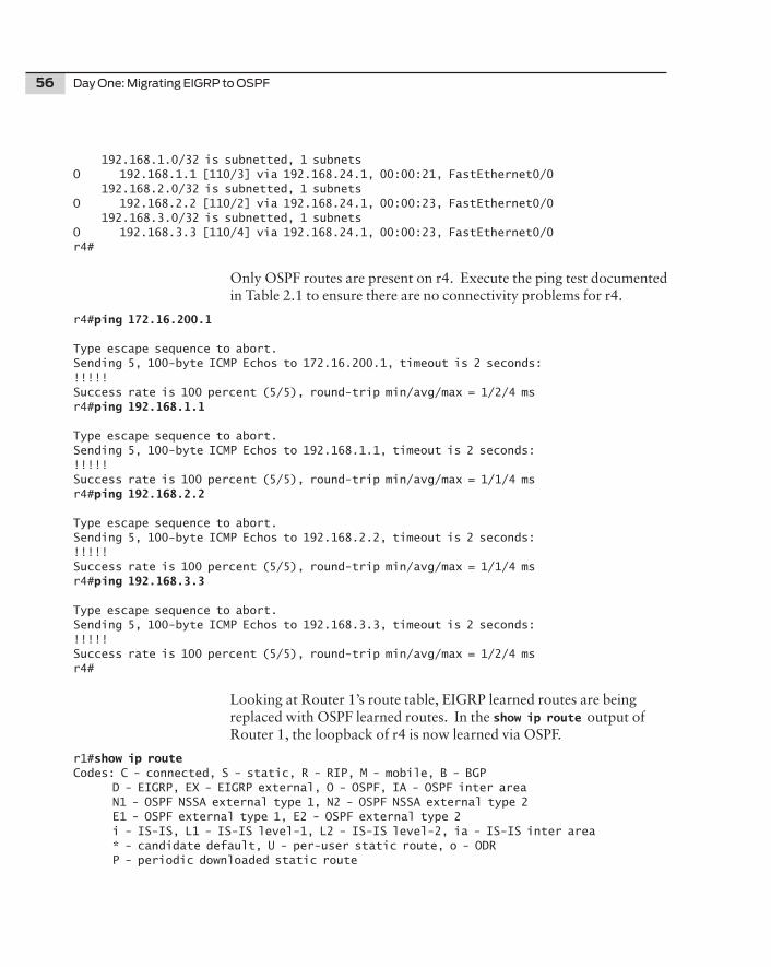
56 Day One: Migrating EIGRP to OSPF
192.168.1.0/32 is subnetted, 1 subnetsO 192.168.1.1 [110/3] via 192.168.24.1, 00:00:21, FastEthernet0/0 192.168.2.0/32 is subnetted, 1 subnetsO 192.168.2.2 [110/2] via 192.168.24.1, 00:00:23, FastEthernet0/0 192.168.3.0/32 is subnetted, 1 subnetsO 192.168.3.3 [110/4] via 192.168.24.1, 00:00:23, FastEthernet0/0r4#
Only OSPF routes are present on r4. Execute the ping test documented in Table 2.1 to ensure there are no connectivity problems for r4.
r4#ping 172.16.200.1
Type escape sequence to abort.Sending 5, 100-byte ICMP Echos to 172.16.200.1, timeout is 2 seconds:!!!!!Success rate is 100 percent (5/5), round-trip min/avg/max = 1/2/4 msr4#ping 192.168.1.1
Type escape sequence to abort.Sending 5, 100-byte ICMP Echos to 192.168.1.1, timeout is 2 seconds:!!!!!Success rate is 100 percent (5/5), round-trip min/avg/max = 1/1/4 msr4#ping 192.168.2.2
Type escape sequence to abort.Sending 5, 100-byte ICMP Echos to 192.168.2.2, timeout is 2 seconds:!!!!!Success rate is 100 percent (5/5), round-trip min/avg/max = 1/1/4 msr4#ping 192.168.3.3
Type escape sequence to abort.Sending 5, 100-byte ICMP Echos to 192.168.3.3, timeout is 2 seconds:!!!!!Success rate is 100 percent (5/5), round-trip min/avg/max = 1/2/4 msr4#
Looking at Router 1’s route table, EIGRP learned routes are being replaced with OSPF learned routes. In the show ip route output of Router 1, the loopback of r4 is now learned via OSPF.
r1#show ip route Codes: C - connected, S - static, R - RIP, M - mobile, B - BGP D - EIGRP, EX - EIGRP external, O - OSPF, IA - OSPF inter area N1 - OSPF NSSA external type 1, N2 - OSPF NSSA external type 2 E1 - OSPF external type 1, E2 - OSPF external type 2 i - IS-IS, L1 - IS-IS level-1, L2 - IS-IS level-2, ia - IS-IS inter area * - candidate default, U - per-user static route, o - ODR P - periodic downloaded static route
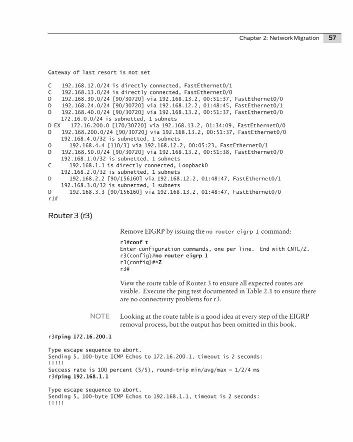
Chapter 2: Network Migration 57
Gateway of last resort is not set
C 192.168.12.0/24 is directly connected, FastEthernet0/1C 192.168.13.0/24 is directly connected, FastEthernet0/0D 192.168.30.0/24 [90/30720] via 192.168.13.2, 00:51:37, FastEthernet0/0D 192.168.24.0/24 [90/30720] via 192.168.12.2, 01:48:45, FastEthernet0/1D 192.168.40.0/24 [90/30720] via 192.168.13.2, 00:51:37, FastEthernet0/0 172.16.0.0/24 is subnetted, 1 subnetsD EX 172.16.200.0 [170/30720] via 192.168.13.2, 01:34:09, FastEthernet0/0D 192.168.200.0/24 [90/30720] via 192.168.13.2, 00:51:37, FastEthernet0/0 192.168.4.0/32 is subnetted, 1 subnetsO 192.168.4.4 [110/3] via 192.168.12.2, 00:05:23, FastEthernet0/1D 192.168.50.0/24 [90/30720] via 192.168.13.2, 00:51:38, FastEthernet0/0 192.168.1.0/32 is subnetted, 1 subnetsC 192.168.1.1 is directly connected, Loopback0 192.168.2.0/32 is subnetted, 1 subnetsD 192.168.2.2 [90/156160] via 192.168.12.2, 01:48:47, FastEthernet0/1 192.168.3.0/32 is subnetted, 1 subnetsD 192.168.3.3 [90/156160] via 192.168.13.2, 01:48:47, FastEthernet0/0r1#
Router 3 (r3)
Remove EIGRP by issuing the no router eigrp 1 command:
r3#conf t Enter configuration commands, one per line. End with CNTL/Z.r3(config)#no router eigrp 1r3(config)#^Zr3#
View the route table of Router 3 to ensure all expected routes are visible. Execute the ping test documented in Table 2.1 to ensure there are no connectivity problems for r3.
NOTE Looking at the route table is a good idea at every step of the EIGRP removal process, but the output has been omitted in this book.
r3#ping 172.16.200.1
Type escape sequence to abort.Sending 5, 100-byte ICMP Echos to 172.16.200.1, timeout is 2 seconds:!!!!!Success rate is 100 percent (5/5), round-trip min/avg/max = 1/2/4 msr3#ping 192.168.1.1
Type escape sequence to abort.Sending 5, 100-byte ICMP Echos to 192.168.1.1, timeout is 2 seconds:!!!!!
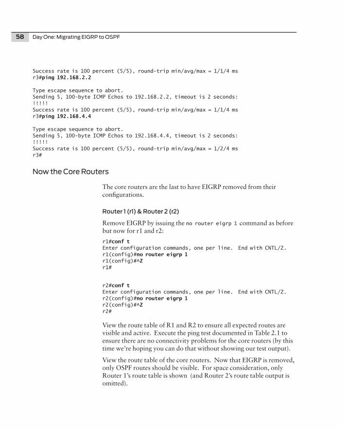
58 Day One: Migrating EIGRP to OSPF
Success rate is 100 percent (5/5), round-trip min/avg/max = 1/1/4 msr3#ping 192.168.2.2
Type escape sequence to abort.Sending 5, 100-byte ICMP Echos to 192.168.2.2, timeout is 2 seconds:!!!!!Success rate is 100 percent (5/5), round-trip min/avg/max = 1/1/4 msr3#ping 192.168.4.4
Type escape sequence to abort.Sending 5, 100-byte ICMP Echos to 192.168.4.4, timeout is 2 seconds:!!!!!Success rate is 100 percent (5/5), round-trip min/avg/max = 1/2/4 msr3#
Now the Core Routers
The core routers are the last to have EIGRP removed from their configurations.
Router 1 (r1) & Router 2 (r2)
Remove EIGRP by issuing the no router eigrp 1 command as before but now for r1 and r2:
r1#conf tEnter configuration commands, one per line. End with CNTL/Z.r1(config)#no router eigrp 1r1(config)#^Zr1#
r2#conf tEnter configuration commands, one per line. End with CNTL/Z.r2(config)#no router eigrp 1r2(config)#^Zr2#
View the route table of R1 and R2 to ensure all expected routes are visible and active. Execute the ping test documented in Table 2.1 to ensure there are no connectivity problems for the core routers (by this time we’re hoping you can do that without showing our test output).
View the route table of the core routers. Now that EIGRP is removed, only OSPF routes should be visible. For space consideration, only Router 1’s route table is shown (and Router 2’s route table output is omitted).
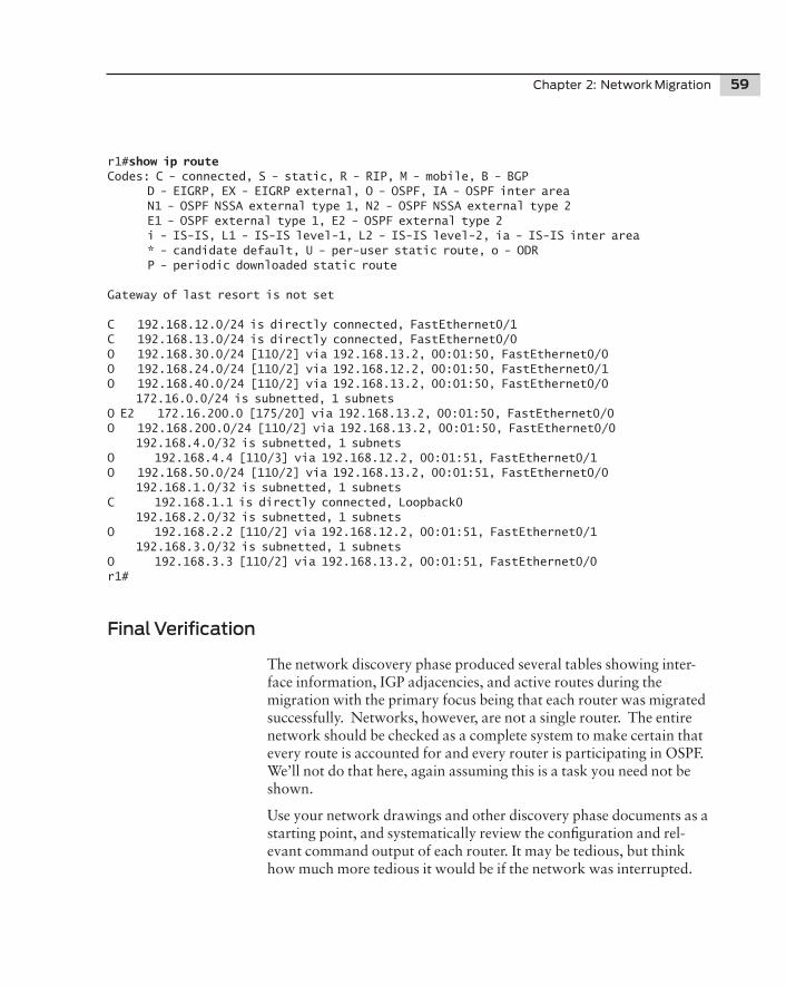
Chapter 2: Network Migration 59
r1#show ip route Codes: C - connected, S - static, R - RIP, M - mobile, B - BGP D - EIGRP, EX - EIGRP external, O - OSPF, IA - OSPF inter area N1 - OSPF NSSA external type 1, N2 - OSPF NSSA external type 2 E1 - OSPF external type 1, E2 - OSPF external type 2 i - IS-IS, L1 - IS-IS level-1, L2 - IS-IS level-2, ia - IS-IS inter area * - candidate default, U - per-user static route, o - ODR P - periodic downloaded static route
Gateway of last resort is not set
C 192.168.12.0/24 is directly connected, FastEthernet0/1C 192.168.13.0/24 is directly connected, FastEthernet0/0O 192.168.30.0/24 [110/2] via 192.168.13.2, 00:01:50, FastEthernet0/0O 192.168.24.0/24 [110/2] via 192.168.12.2, 00:01:50, FastEthernet0/1O 192.168.40.0/24 [110/2] via 192.168.13.2, 00:01:50, FastEthernet0/0 172.16.0.0/24 is subnetted, 1 subnetsO E2 172.16.200.0 [175/20] via 192.168.13.2, 00:01:50, FastEthernet0/0O 192.168.200.0/24 [110/2] via 192.168.13.2, 00:01:50, FastEthernet0/0 192.168.4.0/32 is subnetted, 1 subnetsO 192.168.4.4 [110/3] via 192.168.12.2, 00:01:51, FastEthernet0/1O 192.168.50.0/24 [110/2] via 192.168.13.2, 00:01:51, FastEthernet0/0 192.168.1.0/32 is subnetted, 1 subnetsC 192.168.1.1 is directly connected, Loopback0 192.168.2.0/32 is subnetted, 1 subnetsO 192.168.2.2 [110/2] via 192.168.12.2, 00:01:51, FastEthernet0/1 192.168.3.0/32 is subnetted, 1 subnetsO 192.168.3.3 [110/2] via 192.168.13.2, 00:01:51, FastEthernet0/0r1#
Final Verification
The network discovery phase produced several tables showing inter-face information, IGP adjacencies, and active routes during the migration with the primary focus being that each router was migrated successfully. Networks, however, are not a single router. The entire network should be checked as a complete system to make certain that every route is accounted for and every router is participating in OSPF. We’ll not do that here, again assuming this is a task you need not be shown.
Use your network drawings and other discovery phase documents as a starting point, and systematically review the configuration and rel-evant command output of each router. It may be tedious, but think how much more tedious it would be if the network was interrupted.
60 Day One: Migrating EIGRP to OSPF
Summary
A successful migration from EIGRP to OSPF does not require special skills, merely attention to detail. A thorough approach to collecting the relevant information is, in the end, the final success criteria, because many configurations tend to have been neglected over the past few months, or even years, and they will be updated and normalized in the migration process. Rigorous testing through each step of the migration process will identify potential troubles right away while minimizing the effect to the network.
Someone famous once said, “It is the minutia that separates success from failure.” That person must have been a networking engineer.

Chapter 3
Adding Junos Devices
Junos OSPF Configuration . . . . . . . . . . . . . . . . . . . . . . .62
Junos Policy . . . . . . . . . . . . . . . . . . . . . . . . . . . . . . . . . . . . 69
62 Day One: Migrating EIGRP to OSPF
Migrating a network from a proprietary protocol to an open standards protocol has great benefits that become apparent almost immediately. The ability to expand the network with a dual vendor strategy is extremely beneficial and the feasibility of incremental upgrades is a common solution for outdated and undersized equipment. Flexibility enables smart business decisions while avoiding the higher costs associated with lock in.
If you’ve read this far you’re ready to reap the benefits of migrating your network to OSPF. Let’s assume that it’s time to expand the network to accommodate increased business growth requirements and port count numbers. Juniper Networks has been chosen as the new network vendor for the network.
Well, this book’s testbed network is in a good position to incorporate new vendors. The OSPF concepts presented in the first chapter are as relevant to IOS as they are to Junos. Simple CLI syntax differences are all that have changed.
Junos OSPF Configuration
To accommodate the multi-vendor expansion, our Day One topology has been updated with the addition of a new router and a new Layer 3 switch as shown in Figure 3.1. The new router, J5, is a Juniper Net-works J2350, and the new switch, SW-EX, is an EX3200. Both devices use Junos and the commonality of the software makes the configura-tion of both the switch and the router identical.
As Figure 3.1 shows, Router J5 is connected to R1 and switch EX-SW is connected to J5.
To add the devices to the network, OSPF will be configured using Junos and the OSPF configurations will be compared against the IOS configuration to show the syntax similarities and differences.
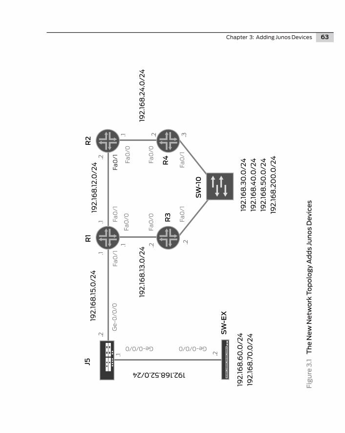
Chapter 3: Adding Junos Devices 63
Fig
ure
3.1
T
he
New
Net
wo
rk T
op
olo
gy
Ad
ds
Jun
os
Dev
ice
s
R2
R1
R3
R4
J5
SW
-EX
SW
-10
192
.16
8.3
0.0
/24
192
.16
8.4
0.0
/24
192
.16
8.5
0.0
/24
192
.16
8.2
00
.0/2
4
192
.16
8.6
0.0
/24
192
.16
8.7
0.0
/24
192.168.52.0/24
192
.16
8.1
5.0
/24
192
.16
8.1
3.0
/24
192
.16
8.1
2.0
/24
192
.16
8.2
4.0
/24
Fa0
/1Fa
0/1
Fa0
/1Fa
0/1
Fa0
/1
Fa0
/0
Fa0
/0
Fa0
/0
Fa0
/0
Ge-0/0/0 Ge-0/0/0
Ge-
0/0
/0
.2
.3
.1
.1.1
.1
.1
.2
.2
.2.2
.2
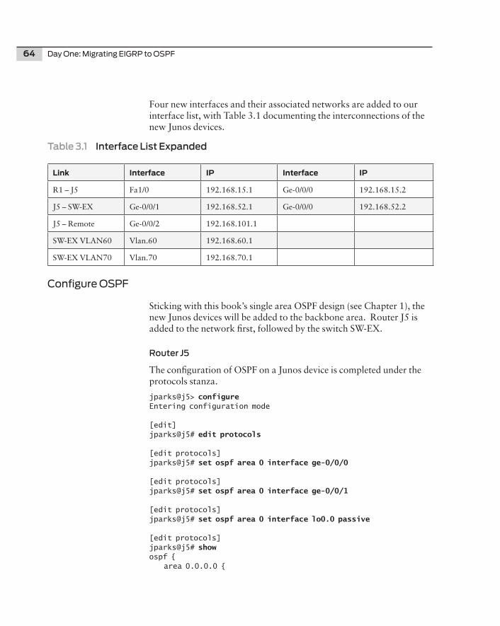
64 Day One: Migrating EIGRP to OSPF
Four new interfaces and their associated networks are added to our interface list, with Table 3.1 documenting the interconnections of the new Junos devices.
Table 3.1 Interface List Expanded
Link Interface IP Interface IP
R1 – J5 Fa1/0 192.168.15.1 Ge-0/0/0 192.168.15.2
J5 – SW-EX Ge-0/0/1 192.168.52.1 Ge-0/0/0 192.168.52.2
J5 – Remote Ge-0/0/2 192.168.101.1
SW-EX VLAN60 Vlan.60 192.168.60.1
SW-EX VLAN70 Vlan.70 192.168.70.1
Configure OSPF
Sticking with this book’s single area OSPF design (see Chapter 1), the new Junos devices will be added to the backbone area. Router J5 is added to the network first, followed by the switch SW-EX.
Router J5
The configuration of OSPF on a Junos device is completed under the protocols stanza.
jparks@j5> configure Entering configuration mode
[edit]jparks@j5# edit protocols
[edit protocols]jparks@j5# set ospf area 0 interface ge-0/0/0
[edit protocols]jparks@j5# set ospf area 0 interface ge-0/0/1
[edit protocols]jparks@j5# set ospf area 0 interface lo0.0 passive
[edit protocols]jparks@j5# show ospf { area 0.0.0.0 {
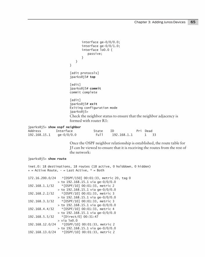
Chapter 3: Adding Junos Devices 65
interface ge-0/0/0.0; interface ge-0/0/1.0; interface lo0.0 { passive; } }}
[edit protocols]jparks@j5# top
[edit]jparks@j5# commit commit complete
[edit]jparks@j5# exit Exiting configuration modejparks@j5>
Check the neighbor status to ensure that the neighbor adjacency is formed with router R1:
jparks@j5> show ospf neighbor Address Interface State ID Pri Dead192.168.15.1 ge-0/0/0.0 Full 192.168.1.1 1 33
Once the OSPF neighbor relationship is established, the route table for J5 can be viewed to ensure that it is receiving the routes from the rest of the network:
jparks@j5> show route
inet.0: 18 destinations, 18 routes (18 active, 0 holddown, 0 hidden)+ = Active Route, - = Last Active, * = Both
172.16.200.0/24 *[OSPF/150] 00:01:33, metric 20, tag 0 > to 192.168.15.1 via ge-0/0/0.0192.168.1.1/32 *[OSPF/10] 00:01:33, metric 2 > to 192.168.15.1 via ge-0/0/0.0192.168.2.2/32 *[OSPF/10] 00:01:33, metric 3 > to 192.168.15.1 via ge-0/0/0.0192.168.3.3/32 *[OSPF/10] 00:01:33, metric 3 > to 192.168.15.1 via ge-0/0/0.0192.168.4.4/32 *[OSPF/10] 00:01:33, metric 4 > to 192.168.15.1 via ge-0/0/0.0192.168.5.5/32 *[Direct/0] 00:31:47 > via lo0.0192.168.12.0/24 *[OSPF/10] 00:01:33, metric 2 > to 192.168.15.1 via ge-0/0/0.0192.168.13.0/24 *[OSPF/10] 00:01:33, metric 2

66 Day One: Migrating EIGRP to OSPF
> to 192.168.15.1 via ge-0/0/0.0192.168.15.0/24 *[Direct/0] 00:31:48 > via ge-0/0/0.0192.168.15.2/32 *[Local/0] 00:31:48 Local via ge-0/0/0.0192.168.24.0/24 *[OSPF/10] 00:01:33, metric 3 > to 192.168.15.1 via ge-0/0/0.0192.168.30.0/24 *[OSPF/10] 00:01:33, metric 3 > to 192.168.15.1 via ge-0/0/0.0192.168.40.0/24 *[OSPF/10] 00:01:33, metric 3 > to 192.168.15.1 via ge-0/0/0.0192.168.50.0/24 *[OSPF/10] 00:01:33, metric 3 > to 192.168.15.1 via ge-0/0/0.0192.168.52.0/24 *[Direct/0] 00:31:47 > via ge-0/0/1.0192.168.52.1/32 *[Local/0] 00:31:47 Local via ge-0/0/1.0192.168.200.0/24 *[OSPF/10] 00:01:33, metric 3 > to 192.168.15.1 via ge-0/0/0.0224.0.0.5/32 *[OSPF/10] 00:01:43, metric 1 MultiRecv
jparks@j5>
Router J5 is connected to the network and receiving all of the routes from the legacy network. Switch SW-EX is added to the network next, and thanks to both devices running the same Junos software, the steps are the same.
Switch SW-EX
The configuration of OSPF on the switch is completed, again, under the protocols stanza:
jparks@SW-EX> configure Entering configuration mode
[edit]jparks@SW-EX# edit protocols
[edit protocols]jparks@SW-EX# set ospf area 0.0.0.0 interface all
[edit protocols]jparks@SW-EX# set ospf area 0.0.0.0 interface lo0.0 passive
[edit protocols]jparks@SW-EX# set ospf area 0.0.0.0 interface me0.0 disable
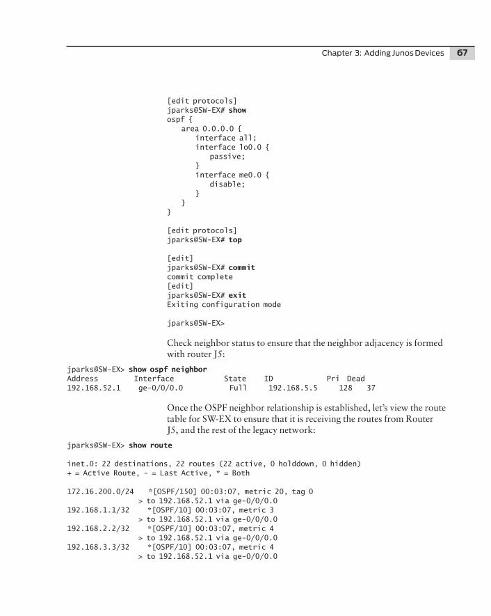
Chapter 3: Adding Junos Devices 67
[edit protocols]jparks@SW-EX# show ospf { area 0.0.0.0 { interface all; interface lo0.0 { passive; } interface me0.0 { disable; } }}
[edit protocols]jparks@SW-EX# top
[edit]jparks@SW-EX# commit commit complete[edit]jparks@SW-EX# exit Exiting configuration mode
jparks@SW-EX>
Check neighbor status to ensure that the neighbor adjacency is formed with router J5:
jparks@SW-EX> show ospf neighbor Address Interface State ID Pri Dead192.168.52.1 ge-0/0/0.0 Full 192.168.5.5 128 37
Once the OSPF neighbor relationship is established, let’s view the route table for SW-EX to ensure that it is receiving the routes from Router J5, and the rest of the legacy network:
jparks@SW-EX> show route
inet.0: 22 destinations, 22 routes (22 active, 0 holddown, 0 hidden)+ = Active Route, - = Last Active, * = Both
172.16.200.0/24 *[OSPF/150] 00:03:07, metric 20, tag 0 > to 192.168.52.1 via ge-0/0/0.0192.168.1.1/32 *[OSPF/10] 00:03:07, metric 3 > to 192.168.52.1 via ge-0/0/0.0192.168.2.2/32 *[OSPF/10] 00:03:07, metric 4 > to 192.168.52.1 via ge-0/0/0.0192.168.3.3/32 *[OSPF/10] 00:03:07, metric 4 > to 192.168.52.1 via ge-0/0/0.0
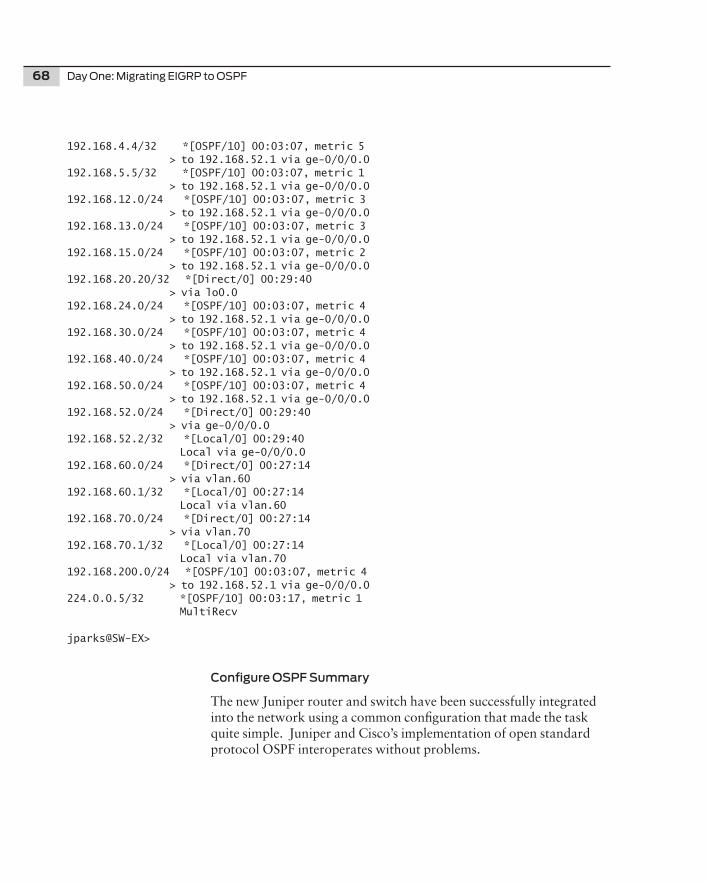
68 Day One: Migrating EIGRP to OSPF
192.168.4.4/32 *[OSPF/10] 00:03:07, metric 5 > to 192.168.52.1 via ge-0/0/0.0192.168.5.5/32 *[OSPF/10] 00:03:07, metric 1 > to 192.168.52.1 via ge-0/0/0.0192.168.12.0/24 *[OSPF/10] 00:03:07, metric 3 > to 192.168.52.1 via ge-0/0/0.0192.168.13.0/24 *[OSPF/10] 00:03:07, metric 3 > to 192.168.52.1 via ge-0/0/0.0192.168.15.0/24 *[OSPF/10] 00:03:07, metric 2 > to 192.168.52.1 via ge-0/0/0.0192.168.20.20/32 *[Direct/0] 00:29:40 > via lo0.0192.168.24.0/24 *[OSPF/10] 00:03:07, metric 4 > to 192.168.52.1 via ge-0/0/0.0192.168.30.0/24 *[OSPF/10] 00:03:07, metric 4 > to 192.168.52.1 via ge-0/0/0.0192.168.40.0/24 *[OSPF/10] 00:03:07, metric 4 > to 192.168.52.1 via ge-0/0/0.0192.168.50.0/24 *[OSPF/10] 00:03:07, metric 4 > to 192.168.52.1 via ge-0/0/0.0192.168.52.0/24 *[Direct/0] 00:29:40 > via ge-0/0/0.0192.168.52.2/32 *[Local/0] 00:29:40 Local via ge-0/0/0.0192.168.60.0/24 *[Direct/0] 00:27:14 > via vlan.60192.168.60.1/32 *[Local/0] 00:27:14 Local via vlan.60192.168.70.0/24 *[Direct/0] 00:27:14 > via vlan.70192.168.70.1/32 *[Local/0] 00:27:14 Local via vlan.70192.168.200.0/24 *[OSPF/10] 00:03:07, metric 4 > to 192.168.52.1 via ge-0/0/0.0224.0.0.5/32 *[OSPF/10] 00:03:17, metric 1 MultiRecv
jparks@SW-EX>
Configure OSPF Summary
The new Juniper router and switch have been successfully integrated into the network using a common configuration that made the task quite simple. Juniper and Cisco’s implementation of open standard protocol OSPF interoperates without problems.
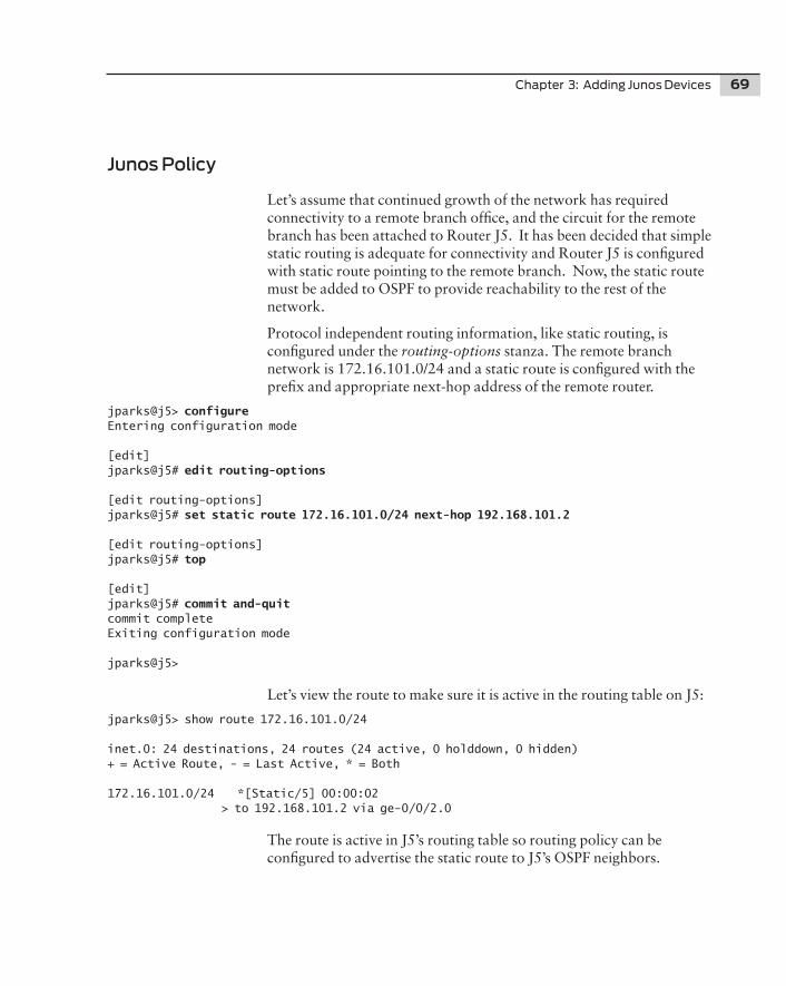
Chapter 3: Adding Junos Devices 69
Junos Policy
Let’s assume that continued growth of the network has required connectivity to a remote branch office, and the circuit for the remote branch has been attached to Router J5. It has been decided that simple static routing is adequate for connectivity and Router J5 is configured with static route pointing to the remote branch. Now, the static route must be added to OSPF to provide reachability to the rest of the network.
Protocol independent routing information, like static routing, is configured under the routing-options stanza. The remote branch network is 172.16.101.0/24 and a static route is configured with the prefix and appropriate next-hop address of the remote router.
jparks@j5> configure Entering configuration mode
[edit]jparks@j5# edit routing-options
[edit routing-options]jparks@j5# set static route 172.16.101.0/24 next-hop 192.168.101.2
[edit routing-options]jparks@j5# top
[edit]jparks@j5# commit and-quit commit completeExiting configuration mode
jparks@j5>
Let’s view the route to make sure it is active in the routing table on J5:
jparks@j5> show route 172.16.101.0/24
inet.0: 24 destinations, 24 routes (24 active, 0 holddown, 0 hidden)+ = Active Route, - = Last Active, * = Both
172.16.101.0/24 *[Static/5] 00:00:02 > to 192.168.101.2 via ge-0/0/2.0
The route is active in J5’s routing table so routing policy can be configured to advertise the static route to J5’s OSPF neighbors.
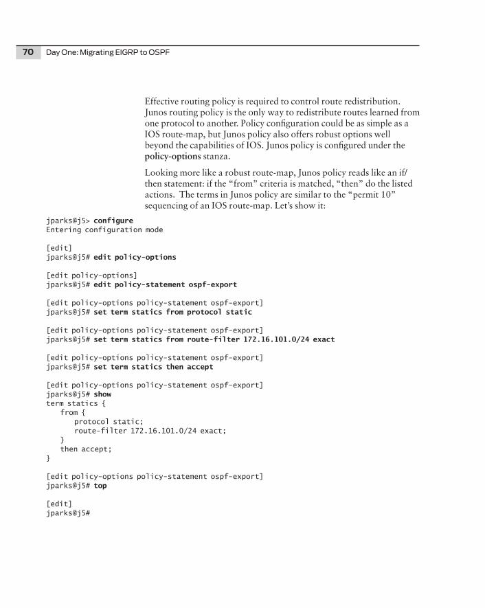
70 Day One: Migrating EIGRP to OSPF
Effective routing policy is required to control route redistribution. Junos routing policy is the only way to redistribute routes learned from one protocol to another. Policy configuration could be as simple as a IOS route-map, but Junos policy also offers robust options well beyond the capabilities of IOS. Junos policy is configured under the policy-options stanza.
Looking more like a robust route-map, Junos policy reads like an if/then statement: if the “from” criteria is matched, “then” do the listed actions. The terms in Junos policy are similar to the “permit 10” sequencing of an IOS route-map. Let’s show it:
jparks@j5> configure Entering configuration mode
[edit]jparks@j5# edit policy-options
[edit policy-options]jparks@j5# edit policy-statement ospf-export
[edit policy-options policy-statement ospf-export]jparks@j5# set term statics from protocol static
[edit policy-options policy-statement ospf-export]jparks@j5# set term statics from route-filter 172.16.101.0/24 exact
[edit policy-options policy-statement ospf-export]jparks@j5# set term statics then accept
[edit policy-options policy-statement ospf-export]jparks@j5# show term statics { from { protocol static; route-filter 172.16.101.0/24 exact; } then accept;}
[edit policy-options policy-statement ospf-export]jparks@j5# top
[edit]jparks@j5#
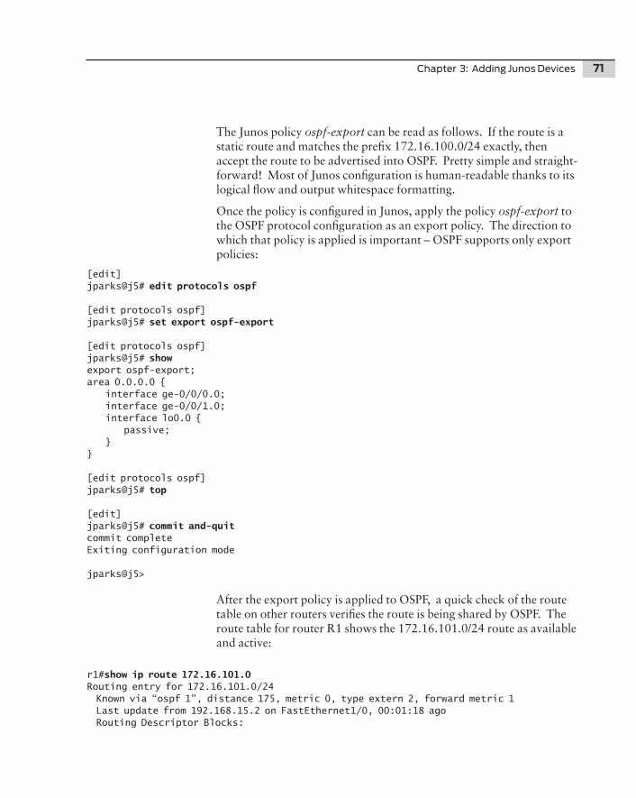
Chapter 3: Adding Junos Devices 71
The Junos policy ospf-export can be read as follows. If the route is a static route and matches the prefix 172.16.100.0/24 exactly, then accept the route to be advertised into OSPF. Pretty simple and straight-forward! Most of Junos configuration is human-readable thanks to its logical flow and output whitespace formatting.
Once the policy is configured in Junos, apply the policy ospf-export to the OSPF protocol configuration as an export policy. The direction to which that policy is applied is important – OSPF supports only export policies:
[edit]jparks@j5# edit protocols ospf
[edit protocols ospf]jparks@j5# set export ospf-export
[edit protocols ospf]jparks@j5# show export ospf-export;area 0.0.0.0 { interface ge-0/0/0.0; interface ge-0/0/1.0; interface lo0.0 { passive; }}
[edit protocols ospf]jparks@j5# top
[edit]jparks@j5# commit and-quit commit completeExiting configuration mode
jparks@j5>
After the export policy is applied to OSPF, a quick check of the route table on other routers verifies the route is being shared by OSPF. The route table for router R1 shows the 172.16.101.0/24 route as available and active:
r1#show ip route 172.16.101.0 Routing entry for 172.16.101.0/24 Known via “ospf 1”, distance 175, metric 0, type extern 2, forward metric 1 Last update from 192.168.15.2 on FastEthernet1/0, 00:01:18 ago Routing Descriptor Blocks:
72 Day One: Migrating EIGRP to OSPF
* 192.168.15.2, from 192.168.5.5, 00:01:18 ago, via FastEthernet1/0 Route metric is 0, traffic share count is 1
r1#
MORE For more about Junos policy configuration, try the Junos Cookbook (by Aviva Garrett, 2006, O’Reilly Media) or Junos Enterprise Routing (by Marschke & Reynolds, 2007, O’Reilly Media), at www.juniper.net/books. Junos policy is so robust in capability that there could be an entire Day One series written solely on that topic.
Chapter 4
IOS to Junos Comparison
Protocol Comparison . . . . . . . . . . . . . . . . . . . . . . . . . . . 74
Policy Comparison . . . . . . . . . . . . . . . . . . . . . . . . . . . . . . 74
OSPF Comparison . . . . . . . . . . . . . . . . . . . . . . . . . . . . . . . 75
Summary . . . . . . . . . . . . . . . . . . . . . . . . . . . . . . . . . . . . . . . 79
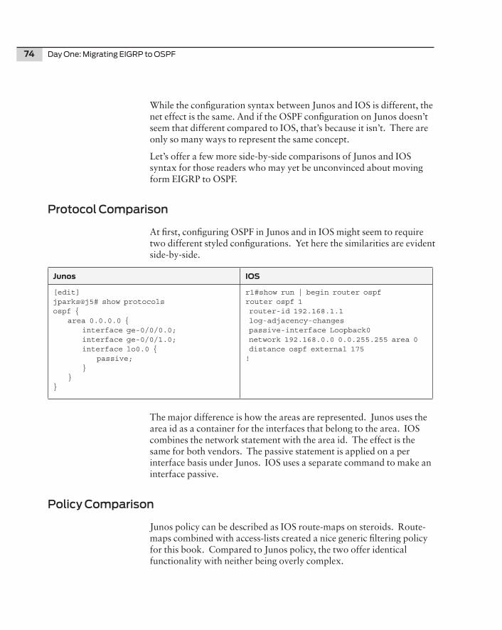
74 Day One: Migrating EIGRP to OSPF
While the configuration syntax between Junos and IOS is different, the net effect is the same. And if the OSPF configuration on Junos doesn’t seem that different compared to IOS, that’s because it isn’t. There are only so many ways to represent the same concept.
Let’s offer a few more side-by-side comparisons of Junos and IOS syntax for those readers who may yet be unconvinced about moving form EIGRP to OSPF.
Protocol Comparison
At first, configuring OSPF in Junos and in IOS might seem to require two different styled configurations. Yet here the similarities are evident side-by-side.
Junos IOS
[edit]jparks@j5# show protocols ospf { area 0.0.0.0 { interface ge-0/0/0.0; interface ge-0/0/1.0; interface lo0.0 { passive; } }}
r1#show run | begin router ospf router ospf 1 router-id 192.168.1.1 log-adjacency-changes passive-interface Loopback0 network 192.168.0.0 0.0.255.255 area 0 distance ospf external 175!
The major difference is how the areas are represented. Junos uses the area id as a container for the interfaces that belong to the area. IOS combines the network statement with the area id. The effect is the same for both vendors. The passive statement is applied on a per interface basis under Junos. IOS uses a separate command to make an interface passive.
Policy Comparison
Junos policy can be described as IOS route-maps on steroids. Route-maps combined with access-lists created a nice generic filtering policy for this book. Compared to Junos policy, the two offer identical functionality with neither being overly complex.
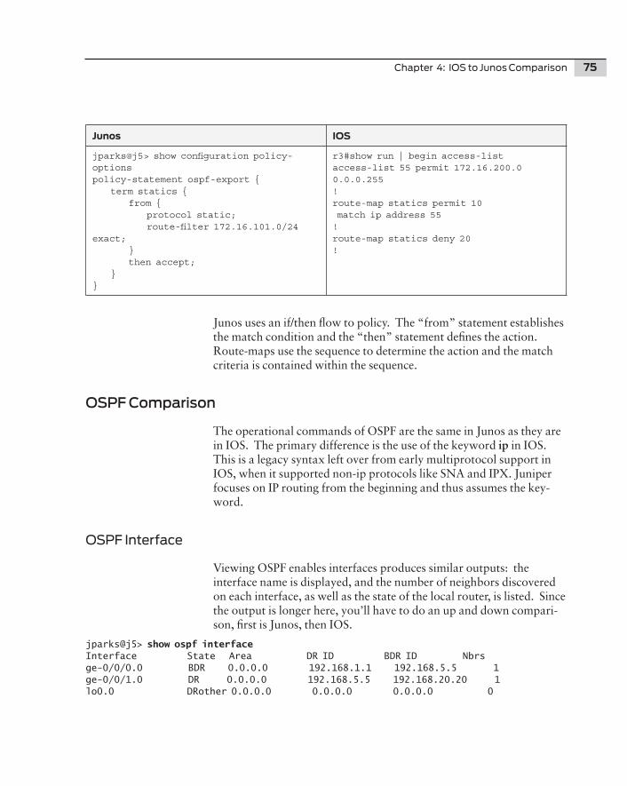
Chapter 4: IOS to Junos Comparison 75
Junos IOS
jparks@j5> show configuration policy-options policy-statement ospf-export { term statics { from { protocol static; route-filter 172.16.101.0/24 exact; } then accept; }}
r3#show run | begin access-listaccess-list 55 permit 172.16.200.0 0.0.0.255!route-map statics permit 10 match ip address 55!route-map statics deny 20!
Junos uses an if/then flow to policy. The “from” statement establishes the match condition and the “then” statement defines the action. Route-maps use the sequence to determine the action and the match criteria is contained within the sequence.
OSPF Comparison
The operational commands of OSPF are the same in Junos as they are in IOS. The primary difference is the use of the keyword ip in IOS. This is a legacy syntax left over from early multiprotocol support in IOS, when it supported non-ip protocols like SNA and IPX. Juniper focuses on IP routing from the beginning and thus assumes the key-word.
OSPF Interface
Viewing OSPF enables interfaces produces similar outputs: the interface name is displayed, and the number of neighbors discovered on each interface, as well as the state of the local router, is listed. Since the output is longer here, you’ll have to do an up and down compari-son, first is Junos, then IOS.
jparks@j5> show ospf interface Interface State Area DR ID BDR ID Nbrsge-0/0/0.0 BDR 0.0.0.0 192.168.1.1 192.168.5.5 1ge-0/0/1.0 DR 0.0.0.0 192.168.5.5 192.168.20.20 1lo0.0 DRother 0.0.0.0 0.0.0.0 0.0.0.0 0
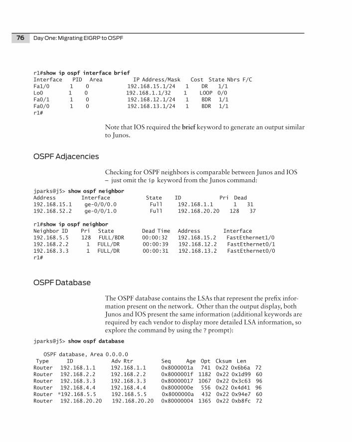
76 Day One: Migrating EIGRP to OSPF
r1#show ip ospf interface briefInterface PID Area IP Address/Mask Cost State Nbrs F/CFa1/0 1 0 192.168.15.1/24 1 DR 1/1Lo0 1 0 192.168.1.1/32 1 LOOP 0/0Fa0/1 1 0 192.168.12.1/24 1 BDR 1/1Fa0/0 1 0 192.168.13.1/24 1 BDR 1/1r1#
Note that IOS required the brief keyword to generate an output similar to Junos.
OSPF Adjacencies
Checking for OSPF neighbors is comparable between Junos and IOS – just omit the ip keyword from the Junos command:
jparks@j5> show ospf neighbor Address Interface State ID Pri Dead192.168.15.1 ge-0/0/0.0 Full 192.168.1.1 1 31192.168.52.2 ge-0/0/1.0 Full 192.168.20.20 128 37
r1#show ip ospf neighbor Neighbor ID Pri State Dead Time Address Interface192.168.5.5 128 FULL/BDR 00:00:32 192.168.15.2 FastEthernet1/0192.168.2.2 1 FULL/DR 00:00:39 192.168.12.2 FastEthernet0/1192.168.3.3 1 FULL/DR 00:00:31 192.168.13.2 FastEthernet0/0r1#
OSPF Database
The OSPF database contains the LSAs that represent the prefix infor-mation present on the network. Other than the output display, both Junos and IOS present the same information (additional keywords are required by each vendor to display more detailed LSA information, so explore the command by using the ? prompt):
jparks@j5> show ospf database
OSPF database, Area 0.0.0.0 Type ID Adv Rtr Seq Age Opt Cksum Len Router 192.168.1.1 192.168.1.1 0x8000001a 741 0x22 0x6b6a 72Router 192.168.2.2 192.168.2.2 0x8000001f 1182 0x22 0x1d99 60Router 192.168.3.3 192.168.3.3 0x80000017 1067 0x22 0x3c63 96Router 192.168.4.4 192.168.4.4 0x8000000e 556 0x22 0x4d41 96Router *192.168.5.5 192.168.5.5 0x8000000a 432 0x22 0x94e7 60Router 192.168.20.20 192.168.20.20 0x80000004 1365 0x22 0xb8fc 72
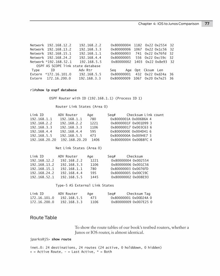
Chapter 4: IOS to Junos Comparison 77
Network 192.168.12.2 192.168.2.2 0x80000004 1182 0x22 0x2554 32Network 192.168.13.2 192.168.3.3 0x80000006 1067 0x22 0x1c56 32Network 192.168.15.1 192.168.1.1 0x80000003 741 0x22 0x76fd 32Network 192.168.24.2 192.168.4.4 0x80000005 556 0x22 0xc59c 32Network *192.168.52.1 192.168.5.5 0x80000002 1403 0x22 0x8e93 32 OSPF AS SCOPE link state database Type ID Adv Rtr Seq Age Opt Cksum Len Extern *172.16.101.0 192.168.5.5 0x80000001 432 0x22 0xd24a 36Extern 172.16.200.0 192.168.3.3 0x80000009 1067 0x20 0x7e25 36
r1#show ip ospf database
OSPF Router with ID (192.168.1.1) (Process ID 1)
Router Link States (Area 0)
Link ID ADV Router Age Seq# Checksum Link count192.168.1.1 192.168.1.1 780 0x8000001A 0x006B6A 4192.168.2.2 192.168.2.2 1221 0x8000001F 0x001D99 3192.168.3.3 192.168.3.3 1106 0x80000017 0x003C63 6192.168.4.4 192.168.4.4 595 0x8000000E 0x004D41 6192.168.5.5 192.168.5.5 473 0x8000000A 0x0094E7 3192.168.20.20 192.168.20.20 1406 0x80000004 0x00B8FC 4
Net Link States (Area 0)
Link ID ADV Router Age Seq# Checksum192.168.12.2 192.168.2.2 1221 0x80000004 0x002554192.168.13.2 192.168.3.3 1106 0x80000006 0x001C56192.168.15.1 192.168.1.1 780 0x80000003 0x0076FD192.168.24.2 192.168.4.4 595 0x80000005 0x00C59C192.168.52.1 192.168.5.5 1445 0x80000002 0x008E93
Type-5 AS External Link States
Link ID ADV Router Age Seq# Checksum Tag172.16.101.0 192.168.5.5 473 0x80000001 0x00D24A 0172.16.200.0 192.168.3.3 1106 0x80000009 0x007E25 0
Route Table
To show the route tables of our book’s testbed routers, whether a Junos or IOS router, is almost identical.
jparks@j5> show route
inet.0: 24 destinations, 24 routes (24 active, 0 holddown, 0 hidden)+ = Active Route, - = Last Active, * = Both
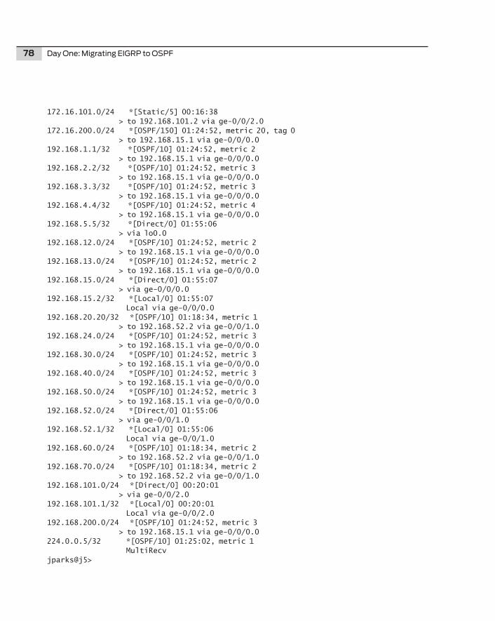
78 Day One: Migrating EIGRP to OSPF
172.16.101.0/24 *[Static/5] 00:16:38 > to 192.168.101.2 via ge-0/0/2.0172.16.200.0/24 *[OSPF/150] 01:24:52, metric 20, tag 0 > to 192.168.15.1 via ge-0/0/0.0192.168.1.1/32 *[OSPF/10] 01:24:52, metric 2 > to 192.168.15.1 via ge-0/0/0.0192.168.2.2/32 *[OSPF/10] 01:24:52, metric 3 > to 192.168.15.1 via ge-0/0/0.0192.168.3.3/32 *[OSPF/10] 01:24:52, metric 3 > to 192.168.15.1 via ge-0/0/0.0192.168.4.4/32 *[OSPF/10] 01:24:52, metric 4 > to 192.168.15.1 via ge-0/0/0.0192.168.5.5/32 *[Direct/0] 01:55:06 > via lo0.0192.168.12.0/24 *[OSPF/10] 01:24:52, metric 2 > to 192.168.15.1 via ge-0/0/0.0192.168.13.0/24 *[OSPF/10] 01:24:52, metric 2 > to 192.168.15.1 via ge-0/0/0.0192.168.15.0/24 *[Direct/0] 01:55:07 > via ge-0/0/0.0192.168.15.2/32 *[Local/0] 01:55:07 Local via ge-0/0/0.0192.168.20.20/32 *[OSPF/10] 01:18:34, metric 1 > to 192.168.52.2 via ge-0/0/1.0192.168.24.0/24 *[OSPF/10] 01:24:52, metric 3 > to 192.168.15.1 via ge-0/0/0.0192.168.30.0/24 *[OSPF/10] 01:24:52, metric 3 > to 192.168.15.1 via ge-0/0/0.0192.168.40.0/24 *[OSPF/10] 01:24:52, metric 3 > to 192.168.15.1 via ge-0/0/0.0192.168.50.0/24 *[OSPF/10] 01:24:52, metric 3 > to 192.168.15.1 via ge-0/0/0.0192.168.52.0/24 *[Direct/0] 01:55:06 > via ge-0/0/1.0192.168.52.1/32 *[Local/0] 01:55:06 Local via ge-0/0/1.0192.168.60.0/24 *[OSPF/10] 01:18:34, metric 2 > to 192.168.52.2 via ge-0/0/1.0192.168.70.0/24 *[OSPF/10] 01:18:34, metric 2 > to 192.168.52.2 via ge-0/0/1.0192.168.101.0/24 *[Direct/0] 00:20:01 > via ge-0/0/2.0192.168.101.1/32 *[Local/0] 00:20:01 Local via ge-0/0/2.0192.168.200.0/24 *[OSPF/10] 01:24:52, metric 3 > to 192.168.15.1 via ge-0/0/0.0224.0.0.5/32 *[OSPF/10] 01:25:02, metric 1 MultiRecvjparks@j5>
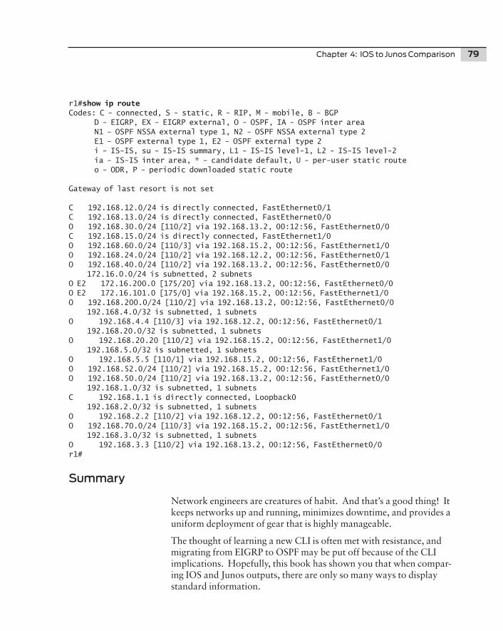
Chapter 4: IOS to Junos Comparison 79
r1#show ip routeCodes: C - connected, S - static, R - RIP, M - mobile, B - BGP D - EIGRP, EX - EIGRP external, O - OSPF, IA - OSPF inter area N1 - OSPF NSSA external type 1, N2 - OSPF NSSA external type 2 E1 - OSPF external type 1, E2 - OSPF external type 2 i - IS-IS, su - IS-IS summary, L1 - IS-IS level-1, L2 - IS-IS level-2 ia - IS-IS inter area, * - candidate default, U - per-user static route o - ODR, P - periodic downloaded static route
Gateway of last resort is not set
C 192.168.12.0/24 is directly connected, FastEthernet0/1C 192.168.13.0/24 is directly connected, FastEthernet0/0O 192.168.30.0/24 [110/2] via 192.168.13.2, 00:12:56, FastEthernet0/0C 192.168.15.0/24 is directly connected, FastEthernet1/0O 192.168.60.0/24 [110/3] via 192.168.15.2, 00:12:56, FastEthernet1/0O 192.168.24.0/24 [110/2] via 192.168.12.2, 00:12:56, FastEthernet0/1O 192.168.40.0/24 [110/2] via 192.168.13.2, 00:12:56, FastEthernet0/0 172.16.0.0/24 is subnetted, 2 subnetsO E2 172.16.200.0 [175/20] via 192.168.13.2, 00:12:56, FastEthernet0/0O E2 172.16.101.0 [175/0] via 192.168.15.2, 00:12:56, FastEthernet1/0O 192.168.200.0/24 [110/2] via 192.168.13.2, 00:12:56, FastEthernet0/0 192.168.4.0/32 is subnetted, 1 subnetsO 192.168.4.4 [110/3] via 192.168.12.2, 00:12:56, FastEthernet0/1 192.168.20.0/32 is subnetted, 1 subnetsO 192.168.20.20 [110/2] via 192.168.15.2, 00:12:56, FastEthernet1/0 192.168.5.0/32 is subnetted, 1 subnetsO 192.168.5.5 [110/1] via 192.168.15.2, 00:12:56, FastEthernet1/0O 192.168.52.0/24 [110/2] via 192.168.15.2, 00:12:56, FastEthernet1/0O 192.168.50.0/24 [110/2] via 192.168.13.2, 00:12:56, FastEthernet0/0 192.168.1.0/32 is subnetted, 1 subnetsC 192.168.1.1 is directly connected, Loopback0 192.168.2.0/32 is subnetted, 1 subnetsO 192.168.2.2 [110/2] via 192.168.12.2, 00:12:56, FastEthernet0/1O 192.168.70.0/24 [110/3] via 192.168.15.2, 00:12:56, FastEthernet1/0 192.168.3.0/32 is subnetted, 1 subnetsO 192.168.3.3 [110/2] via 192.168.13.2, 00:12:56, FastEthernet0/0r1#
Summary
Network engineers are creatures of habit. And that’s a good thing! It keeps networks up and running, minimizes downtime, and provides a uniform deployment of gear that is highly manageable.
The thought of learning a new CLI is often met with resistance, and migrating from EIGRP to OSPF may be put off because of the CLI implications. Hopefully, this book has shown you that when compar-ing IOS and Junos outputs, there are only so many ways to display standard information.
80 Day One: Migrating EIGRP to OSPF
The very open nature of OSPF lends the configuration and protocol outputs to render in a similar fashion. And so there are fewer and fewer reasons not to migrate.
There is no great magic to a protocol migration. What may seem initially like a daunting task can be managed, and even conquered, with planning and solid execution. Using the methods described in this book should help enable any network engineer to undertake a project of this type.
Finally, this book ends with a tip.
TIP The lab used to demonstrate the migration in this book was purposely built with minimal gear so that you, the reader, would be encouraged to try a “dry run” before attempting a network migration.
81
Lessons Learned
If you have a good appreciation for both EIGRP and OSPF, the idea of migrating from one protocol to another is less of a mystery and more of an intellectual exercise.
Planning is crucial for a successful migration. The more planning you can accomplish and information you can collect prior to the migration, the smoother the migration process and the better the outcome of the migration. Remember, once the migration begins, the opportunity to collect additional information that may be needed for the migration or verification will be lost.
Updating or creating a network architecture drawing should be a top priority as drawings help you to visualize the network. Additionally, documenting the interfaces and their associated IP addressing is crucial. It is the interfaces that provide the links between the routers, and those links are how the IGP communicates the routing informa-tion from router to router. Also, a steady state snapshot of the routing table ensures that all networks are accounted for after the migration is complete.
There is no such thing as too much information for an IGP migration. The more information you can collect before the migration begins means the more information you can verify after the migration is complete. Remember the 5 “P’s” – proper planning prevents poor performance.
During the migration, it is crucial to follow the plan laid out in the initial preparations. The most important thing to do during the actual migration is to spot check the state of the network during each step. When overlaying a new protocol remember to start at the core and work out to the edge. The core holds the network together and is the apex of the network hierarchy. When removing the legacy protocol, work from the edge of the network back to the core. Methodically follow the plan and verify the state of the network and the migration will go smoothly. The final step is to compare the beginning state of the network with the end result. The two states should be complimen-tary to each other.
So, how do migrate a network? Carefully. One step at a time.
82
What to Do Next & Where to Go
www.juniper.net/dayone
If you’re reading a print version of this booklet, go here to download the PDF version or find out what other Day One booklets are currently available. Follow on Twitter @Day1Junos to receive announcements about new books.
www.juniper.net/junos
Everything you need for Junos adoption and education.
http://forums.juniper.net/jnet
The Juniper-sponsored J-Net Communities forum is dedicated to sharing information, best practices, and questions about Juniper products, technologies, and solutions. Register to participate in this free forum and get access to all the ebooks in the Day One series for free.
www.juniper.net/techpubs
All Juniper-developed product documentation is freely accessible at this site. Find what you need to know about the Junos operating system under each product line.
www.juniper.net/books
Juniper works with multiple book publishers to author and publish technical books on topics essential to network administrators. Check out this ever-expanding list of newly published books.
www.juniper.net/training/fasttrack
Take courses online, on location, or at one of the partner training centers around the world. The Juniper Network Technical Certifica-tion Program (JNTCP) allows you to earn certifications by demon-strating competence in configuration and troubleshooting of Juniper products. If you want the fast track to earning your certifications in enterprise routing, switching, or security use the available online courses, student guides, and lab guides.