david saxby - d-d the aquarium solution has been made of david saxby ... the metal rods which allow...
TRANSCRIPT

2009
Chris Carlton
September 2009
David Saxby

Introduction Much has been made of David Saxby’s tank over the years and whenever it is mentioned or featured it
always attracts comments. Unfortunately, you will occasionally read or hear comments like “You don’t
think he actually looks after that himself”, “He has people come in and do it for him” or “It is amazing
what money can do”. Strangely for one reason or other this tank for some is a very emotive subject.
Everyone is entitled to their opinions irrespective of these views being born out of sheer ignorance
and/or envy! As for me, I’m fortunate enough to have known David for a while now and I’ve had the
pleasure of seeing David and His Tank! Believe me when I say this is David’s tank and David’s alone!!
Yes, he’s not as spritely as he once was and coupled with being a frequent business traveller it’s
understandable that he has to accept help every now and then.
Help or not, David is still very much hands on – there is not much that stops him clambering up a set of
ladders to reach into the tank. I remember a night watching him build something to stop a troublesome
tri-colour tang nibbling on a gargantuous clam. It’s quite a thing to duck out the way of hot acrylic
pinging across the kitchen whilst he’s fashioning some huge cover right there on the kitchen worktop,
using a kitchen knife from the top drawer! And, let’s not forget the drill bit that was sitting on the gas
hob glowing red because we couldn’t find the drill! Make no mistake... this man is reefing-mad just like
the rest of us! There are plenty of stories that could be recalled and shared but those are for another
day.
Past articles and features on David’s tank, even our very own Tank of the Month, have been hung up on
the beauty and the vastness of it. There is nothing wrong with this but it does not really go into any
great detail about how it works and why it works. There is a lot to be learnt from this system and this is
my attempt of learning, understanding and documenting the ‘guts’ of this awe-inspiring system. One
thing to consider here is that even grand as it is, this system is just like any other – it is not safe from
being tinkered with, adjusted here and there, or being overhauled! Like any other reefer David is not
one for resting on his laurels and between drawing the images you'll see a little later on and writing this
introduction David has yet again tweaked the system resulting in a redraw!

The Display Tank Many years back during the planning phase of my own system Martin Lakin told me “whatever you do,
build the biggest possible box of glass that you can – you can deal with the equipment later – once glass
is there it’s there!” The tank, or at least the glass, is one of the few things to have remained constant
throughout the life of this system.
The tank was constructed with a floating base which is
paramount in sizeable tanks as it allows a degree of
flexibility in each pane of glass without putting any
additional stress on the bottom panes. Supporting
the top of the 4’ tall glass panels is a metal collar
which slips over and around the entire tank. The collar
is braced across from side to side and front to back with
the metal rods which allow greater access to the tank when
compared to traditional glass bracing.
The majority of water movement is
provided by a three pump closed loop system that is controlled by
the wave function on the IKS computer system. Water for the
closed loop pumps is drawn from a 40mm pipe manifold that has
two inlet pipes positioned behind a false weir within the tank. The
pipe work for the closed loops goes up and over the top of the
tank rather than through the bottom or side of the tank. The
only holes drilled in the tank are within the weir boxes.
Each of the closed loop pumps has a ball valve on the inlet and
outlet that allow them to be isolated and removed for maintenance. All
of the closed loop pipes have a union connector just below the top of the
tank before they go up and over into the water. This allows for
periodic removal of the pipes for cleaning and/or replacing if
necessary.
In the weir adjacent to the closed loop intake weir an additional tank
connector has been added. This is connected to one of the closed
loop intake pipes but isolated by a ball valve so when the pipes and
pumps need priming after maintenance it is a simple a matter of opening a valve, flooding the pipes and
then closing the valve. Simple, straight-forward and effective!!
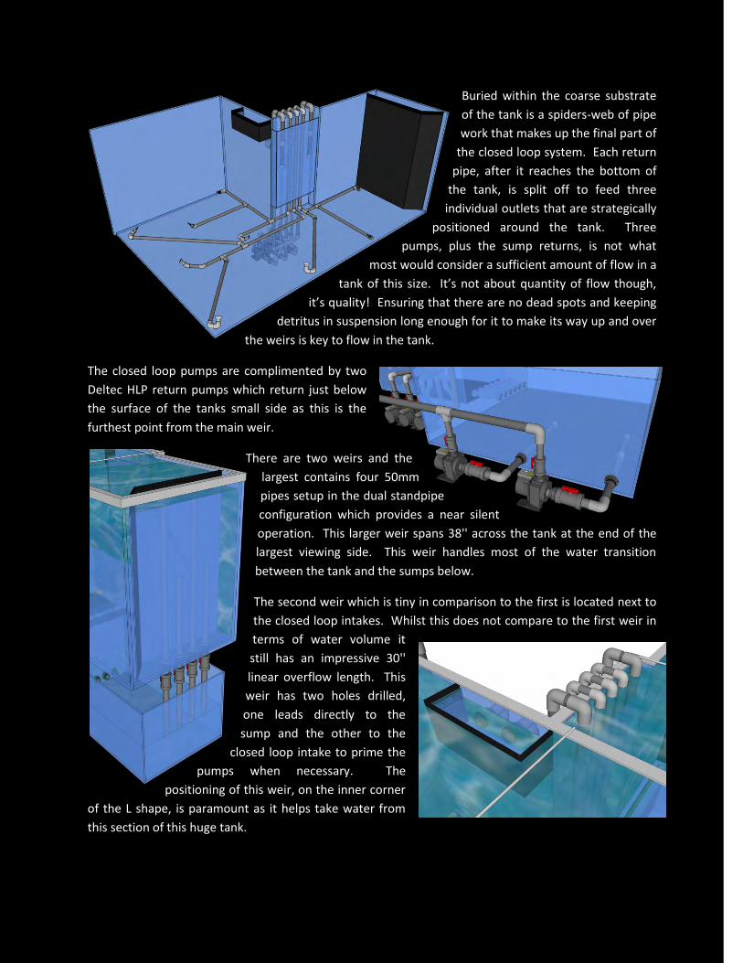
Buried within the coarse substrate
of the tank is a spiders-web of pipe
work that makes up the final part of
the closed loop system. Each return
pipe, after it reaches the bottom of
the tank, is split off to feed three
individual outlets that are strategically
positioned around the tank. Three
pumps, plus the sump returns, is not what
most would consider a sufficient amount of flow in a
tank of this size. It’s not about quantity of flow though,
it’s quality! Ensuring that there are no dead spots and keeping
detritus in suspension long enough for it to make its way up and over
the weirs is key to flow in the tank.
The closed loop pumps are complimented by two
Deltec HLP return pumps which return just below
the surface of the tanks small side as this is the
furthest point from the main weir.
There are two weirs and the
largest contains four 50mm
pipes setup in the dual standpipe
configuration which provides a near silent
operation. This larger weir spans 38'' across the tank at the end of the
largest viewing side. This weir handles most of the water transition
between the tank and the sumps below.
The second weir which is tiny in comparison to the first is located next to
the closed loop intakes. Whilst this does not compare to the first weir in
terms of water volume it
still has an impressive 30''
linear overflow length. This
weir has two holes drilled,
one leads directly to the
sump and the other to the
closed loop intake to prime the
pumps when necessary. The
positioning of this weir, on the inner corner
of the L shape, is paramount as it helps take water from
this section of this huge tank.

As a spectator of the tank you are completely unaware of the weirs presence due to the natural looking
rockwork and extensive coral growth. If you look close enough you can see the teeth of the weir combs
but you’ve got to know they are there and you have to be looking for them!
The sumps Underneath the tank are two separate
sumps which are joined together by six
50mm pipes, each with ball valve to
allow isolation of the sumps for periodic
cleaning. The smaller of the two sumps
is just over 4' by 2 1/2' by 2' deep would
be able to hold 130 gallons if full. The
larger sump is almost a 5 1/2' by 5' by 2'
and capable of holding over 300 gallons. During normal operation the sumps run with a maximum
water height of 12'' despite there only being approximately 20 gallons of water draining down from the
tank in the event of power failure or switching off the return pumps.
The cupboard The cupboard that resides next to the tank is overflowing with equipment and electrics.
They are packed in here tighter than sardines in a tin. In this cupboard, not that you can
see all of it, are the closed loop pumps, a custom built skimmer and a custom built
Phosphate Reactor, as well as an Ozone Generator, an IKS system along
with the numerous plug bars and finally all the other plug sockets and
consumer units.
The custom Phosphate Reactor is not for your average tank! This
one stands at just over 5' tall, takes 5ltrs of ROWAphos every six
weeks and holds an impressive 12 gallons! Not only is it
custom in height but there are three sections in the top
half of the reactor for placing filter mesh and floss to stop
any unwanted particles making their way into the system.
Having been designed specifically for this cupboard the
custom skimmer is in a league of its own. Holding over 35
gallons of water this behemoth of a skimmer stands just over
6' tall with the main chamber being almost 4' in height and
nearly 5' in circumference. Make no mistake - once this
skimmer was in the cupboard it was never coming out! That's not entirely
true - it does come out but it has to go up over the tank! With that in mind
everything has been positioned on the front of the skimmer to ensure it's
completely accessible for maintenance. An Aquabee pump feeds the

skimmer from the sump below and is then returned to that same sump. There are four Aquabee
recirculation pumps, each fitted with the Deltec pinwheel to guarantee the maximum amount of air
possible is fed into the skimmer chamber. Each of these pumps provides 1,500 litres of air every hour
into the chamber. David has built a custom ozone chamber which is fixed to the side of the skimmer
chamber. There is one feed pipe in from the ozone generator that currently splits off to feed each of the
pumps. I say currently because knowing David he’ll build something else before I’ve finished writing
this! Another customisation, which is now a feature of the new Deltec Skimmer range, is the micro
adjustable gate that sits upon the top of the return pipe. This replaced the traditional ball valve on the
skimmer outlet and guarantees that you can get the precise optimum height of water in the chamber to
ensure the skimmer is working at its most efficient. Access to the skimmer cup isn't that straight
forward considering the space to work in and the height at which the cup sits. The skimmer cup is fitted
with a self-cleaning head and is connected directly to waste. It's flushed so often that you never get the
build up of what can be a nasty skimmer cup smell!
The IKS computer system and the plug-bars have been mounted on the back of the door to maximise
the space within the cupboard. The Giesemann HQI lights are not controlled by the IKS system, these
are still connected using the traditional method of contactors and digital timers. The Giesemann T5
Matrix units are connected to the IKS system, as are the closed loop pumps.
Illumination David is a great believer in T5 lighting but despite this you cannot avoid needing stronger lighting on
tank of this depth. T5 lighting wouldn't punch enough light down to corals lower in the tank and those
on the substrate. They may survive but they would not thrive like we want them to. There have been
many variations of light and units above the tank including numerous 1000 watt pendants and twelve
twin 400 watt Giesemann Mega D-D coupled with D-D razor units. These certainly put enough light into
the tank but they also added to the electricity bill given the costs of running them and then needing
multiple chillers/coolers operating to counter-act the heat build up.
Currently above the tank are six Giesemann Mega D-D (twin 400w)
and Giesemann T5 Matrixes. There is a mixture of different
colour temperature tubes in the T5 units which
have helped David achieve the look he's
been longing for whilst retaining
the glistening shimmer of
halide lighting.

Sump Room One This is where the vast majority of equipment and water filtration takes place. Water is pumped here
from the sump beneath the display tank via a 40 metre long 40mm flexi-pipe which journeys its way up
over the tank, through the ceilings of bedrooms, the kitchen and the hall way before it reaches daylight.
It then winds its way around the courtyard into the sump rooms and directly into the two BIG blue VATs.
Each VAT holds approximately 350 gallons of water and excluding the display tank these are the biggest
water containers in the system. They stand an impressive 5ft tall and would need at least three people
to join hands to reach around them!
These two vats are connected to each other via three 40mm pipes to allow water to pass between them.
The left VAT (Blue VAT 1) directly feeds a D-D Chiller that helps maintain the temperature in this part of
this vast system. A Deltec HLP Pump takes a feed from one of the connecting pipes between the two
vats and supplies water to two D-D 4x39w UV Units which
return to the right VAT (Blue VAT 2). The vats also directly feed
the two glass sumps in the room as well as having a pipe linking
straight to the drain when they need to emptied and cleaned.
The two glass sumps are positioned one above the other
flowing end to end and top to bottom. The top sump holds
approximately 110 gallons (500 litres) of water and contains a
substantial caulerpa bed which is lit 24x7 by a T5 unit. The
caulerpa is harvested periodically to remove nutrients and to
encourage further growth. The water leaves via four
standpipes to the bottom sump. The bottom sump contains a heater matrix which is made up of several
500w titanium heaters. There are also heaters placed within each of the vats to allow for independent
control when the vats are isolated as well as ensuring a balanced temperature throughout the system.
Monitoring and control for all the equipment in this room is provided by an IKS system.
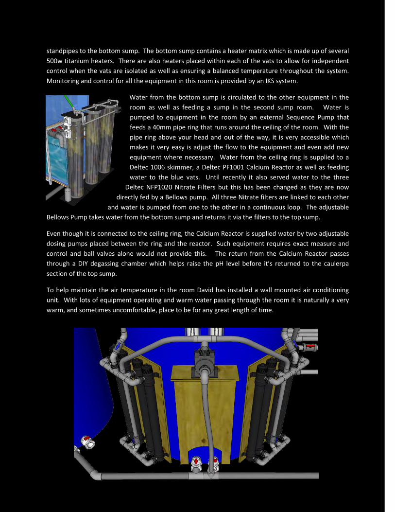
Water from the bottom sump is circulated to the other equipment in the
room as well as feeding a sump in the second sump room. Water is
pumped to equipment in the room by an external Sequence Pump that
feeds a 40mm pipe ring that runs around the ceiling of the room. With the
pipe ring above your head and out of the way, it is very accessible which
makes it very easy is adjust the flow to the equipment and even add new
equipment where necessary. Water from the ceiling ring is supplied to a
Deltec 1006 skimmer, a Deltec PF1001 Calcium Reactor as well as feeding
water to the blue vats. Until recently it also served water to the three
Deltec NFP1020 Nitrate Filters but this has been changed as they are now
directly fed by a Bellows pump. All three Nitrate filters are linked to each other
and water is pumped from one to the other in a continuous loop. The adjustable
Bellows Pump takes water from the bottom sump and returns it via the filters to the top sump.
Even though it is connected to the ceiling ring, the Calcium Reactor is supplied water by two adjustable
dosing pumps placed between the ring and the reactor. Such equipment requires exact measure and
control and ball valves alone would not provide this. The return from the Calcium Reactor passes
through a DIY degassing chamber which helps raise the pH level before it’s returned to the caulerpa
section of the top sump.
To help maintain the air temperature in the room David has installed a wall mounted air conditioning
unit. With lots of equipment operating and warm water passing through the room it is naturally a very
warm, and sometimes uncomfortable, place to be for any great length of time.
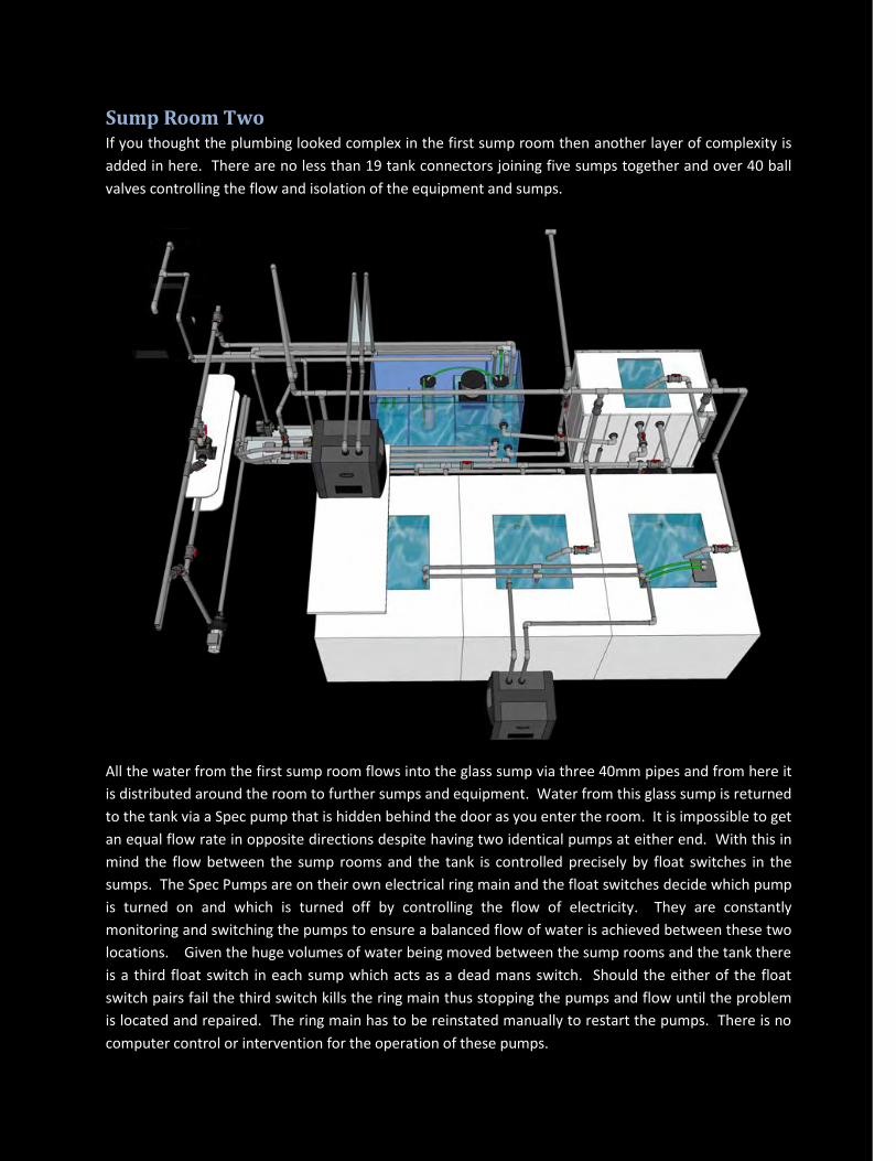
Sump Room Two If you thought the plumbing looked complex in the first sump room then another layer of complexity is
added in here. There are no less than 19 tank connectors joining five sumps together and over 40 ball
valves controlling the flow and isolation of the equipment and sumps.
All the water from the first sump room flows into the glass sump via three 40mm pipes and from here it
is distributed around the room to further sumps and equipment. Water from this glass sump is returned
to the tank via a Spec pump that is hidden behind the door as you enter the room. It is impossible to get
an equal flow rate in opposite directions despite having two identical pumps at either end. With this in
mind the flow between the sump rooms and the tank is controlled precisely by float switches in the
sumps. The Spec Pumps are on their own electrical ring main and the float switches decide which pump
is turned on and which is turned off by controlling the flow of electricity. They are constantly
monitoring and switching the pumps to ensure a balanced flow of water is achieved between these two
locations. Given the huge volumes of water being moved between the sump rooms and the tank there
is a third float switch in each sump which acts as a dead mans switch. Should the either of the float
switch pairs fail the third switch kills the ring main thus stopping the pumps and flow until the problem
is located and repaired. The ring main has to be reinstated manually to restart the pumps. There is no
computer control or intervention for the operation of these pumps.

The last chamber of this glass sump is the lowest point in the system and this is where the float switches
for the top up system reside. The excitement and anticipation of entering the heart of the system
makes most visitors completely unaware that they have stepped down into this sump room!
There is no top up reservoir for this system as the twin pumped RO units produce water quickly enough
to keep on top of the huge evaporation rates. The IKS controls the RO Units so that they are only
operational for a maximum of 90 minutes each morning. This is enough time for them to refill the
system and return the water level back to it's intended volume. Should a float switch failure occur then
after 90 minutes the IKS turns off the RO units and their flow of water which prevents a flood. Running
the units like this helps preserve the pre-filters and membrane longer and it also dilutes the high TDS
water that is produced in the first few moments of switching on an RO unit.
Water is pumped from the glass sump to the other
sumps in this room via an external Sequence Pump.
After teeing off to feed each of these
sumps, the pipe extends through the
wall back to the first sump room
where it also feeds the two blue vats
and the top glass sump. Three of the
sumps in this second room are 220
gallon (1000 litre) containers and
when isolated these are used for the
four weekly water change regime.
The water change process is very slow and very deliberate, and usually completed in 4 - 5 days. The vats
are isolated, drained and given a thorough clean before being refilled by the two pump driven RO units.
The salt is added to the vats and given a thorough mixing before being raised to the temperature of the
tank (25 degrees Celsius). After the mixing process is complete the valves are opened to slowly release
the newly made water to the rest of the system. As you'd expect David uses his own salt on his system
and in recent polls it’s been voted the no. 1 used salt by UK reefers. What may come as a surprise is that
having tested numerous formulas of salt David then guinea-pigged his own tank as the test bed to prove
the salt prior to its release. Proving an unknown on one of the most famous privately owned tanks in
the world is a little bit scary.
Within two of the three water change vats is an Aquabee Pump that circulates water to the other two
vats as well as within its own VAT. The third vat also contains an Aquabee Pump but this feeds a custom
built Phosphate Reactor and a D-D Chiller. You may not think it but David is quite a dab hand at DIY! He
built the Phosphate Reactor from various components of old equipment and standing at nearly 4' tall it's
quite an impressive piece of work!
In addition to the connectors for the Sequence Pump
and the Spec Pump in the last chamber of the sump
there are also two connectors for two Deltec HLP Pumps.
One of the pumps supplies water to two Deltec Eco-

coolers which are housed in an external shed out in the courtyard area. Water returns back from the
coolers under gravity to the first chamber of the sump. The second Deltec HLP Pump splits off and feeds
another D-D Chiller which sits atop a shelf above the first water change vat. The pump also feeds two
Deltec FR509 Reactors which sit in series with each other inside the sump itself. The water returns to
the sump where it can then be distributed around the sump rooms or back to the tank. Also sited in this
sump is a Deltec TS1064 skimmer which skims the water one last time before returning to the tank.
As you’ll have no doubt spotted there are very few single items of equipment. There are three
skimmers, three phosphate reactors, three nitrate filters, three chillers as well as two eco-coolers, three
water change vats, three closed loop pumps, two return pumps, two RO units, IKS systems… the list goes
on.... and this is all very intentional. With a system of this size there has to be redundancy in place. You
simply couldn’t remove the only skimmer for maintenance and not expect the system to suffer during its
absence regardless of that absence being planned or not. Each piece of equipment is backed up by
another piece of equipment.
Each and every piece of equipment and sump or VAT is independently controllable, and isolatable,
which on a system this size is paramount given the constant maintenance schedule.

Water Flow around the Sump Rooms

Concluding Throughout time there will always be advances in this wonderful hobby of ours. The tried and tested
techniques and methods will always work but that should never stop us from wanting to do better and
achieve more. Having seen this system going through various changes it's clear that David will never
stop trying to better than what most of us can only dream about coming home to. It's testament to
David that time and time again he puts his tank on the front line to test and prove these advances.
The first time I met David and cast my eyes on his system I was accompanied by Martin Lakin. As we
made our way down to the sump rooms he turned to me and said “Whatever you do Chris, don’t try to
understand what you’re about to see, and certainly don’t try and draw it. Only David knows how it all
goes together and works.”
No longer is that true! I’ve seen, I’ve learnt and I’ve understood. Hopefully, there are a few more that
now do too!