dave kahn, p.e. - rocky mountain ashrae - home · pdf filekp = proportional gain e = error....
TRANSCRIPT

Dave Kahn, P.E.Dave Kahn, P.E.
Sometimes you get what you ask for resulting in:
The perfect job
ORUnhappy owners & occupantsUnexpected network limitations Product and application problemsAccuracy not correct for applicationInstallation problems RFI’s, Change orders
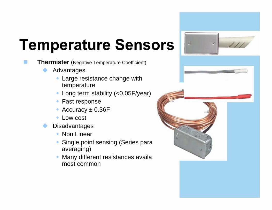
Thermister (Negative Temperature Coefficient)
Advantages Large resistance change with temperatureLong term stability (<0.05F/year)Fast responseAccuracy ± 0.36FLow cost
DisadvantagesNon LinearSingle point sensing (Series parallel for averaging)Many different resistances available 10K most common

RTD Temperature Sensors(Restive Temperature Devices)
Advantages LinearLong term stability (0.005F/Year)Easier to configure for averaging applications1000 Ohm platinum most commonAlso copper & nickel-iron
DisadvantagesLow resistance Vs. temp changeCostAccuracy depends on quality specified
± 0.25% or 0.15% of range
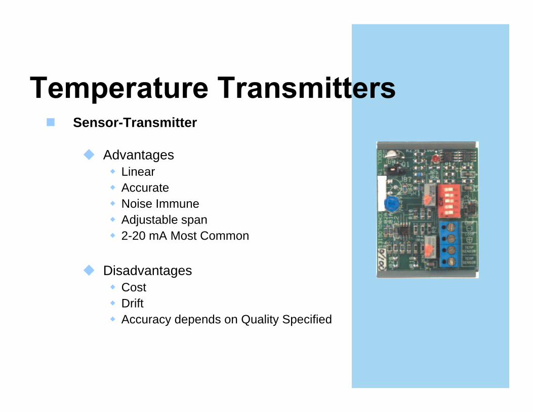
Sensor-Transmitter
Advantages LinearAccurateNoise ImmuneAdjustable span2-20 mA Most Common
DisadvantagesCostDriftAccuracy depends on Quality Specified
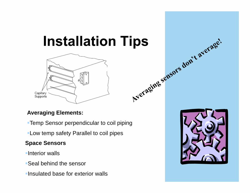
Averaging Elements:
Temp Sensor perpendicular to coil piping
Low temp safety Parallel to coil pipes
Space Sensors
Interior walls
Seal behind the sensor
Insulated base for exterior walls
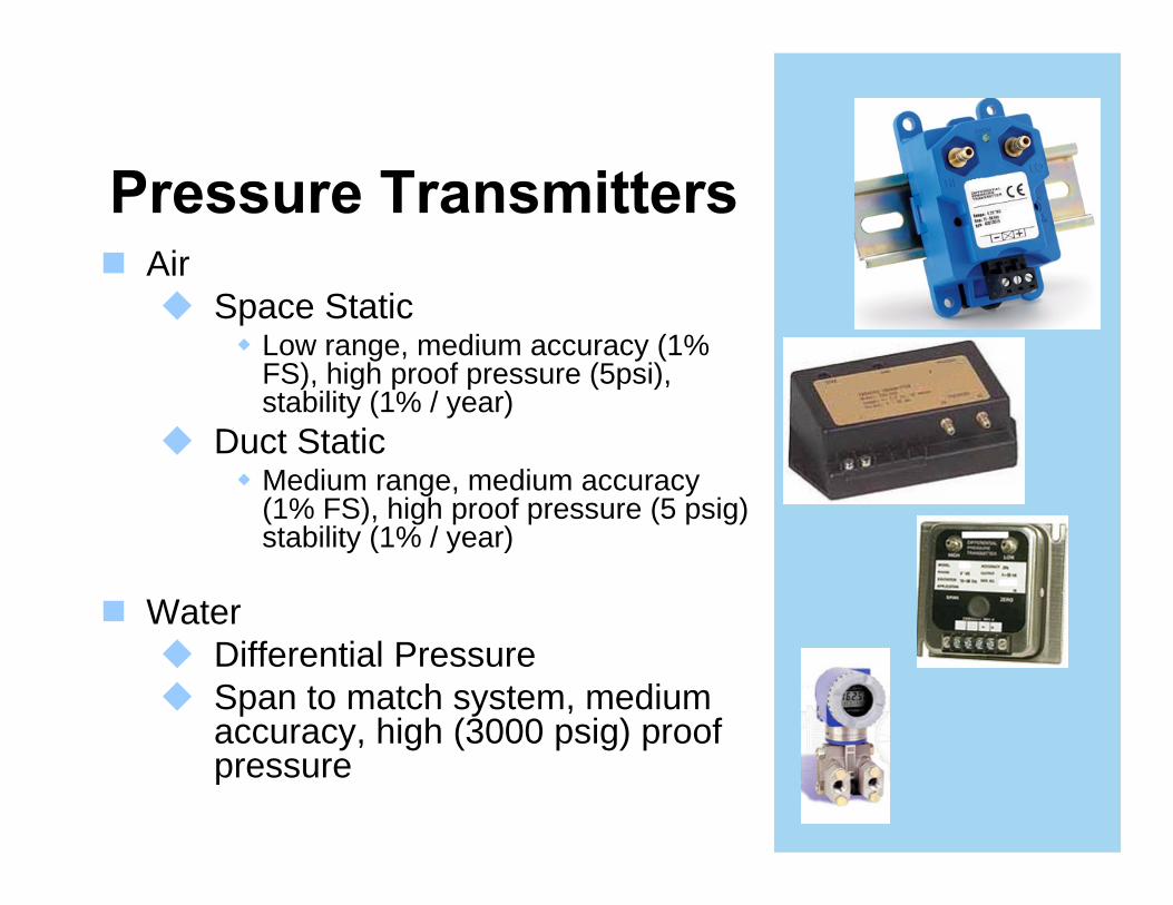
AirSpace Static
Low range, medium accuracy (1% FS), high proof pressure (5psi), stability (1% / year)
Duct StaticMedium range, medium accuracy (1% FS), high proof pressure (5 psig) stability (1% / year)
WaterDifferential PressureSpan to match system, medium accuracy, high (3000 psig) proof pressure
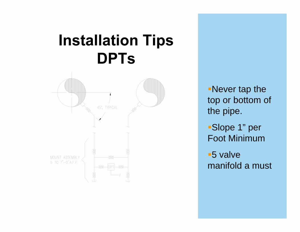
Never tap the top or bottom of the pipe.
Slope 1” per Foot Minimum
5 valve manifold a must
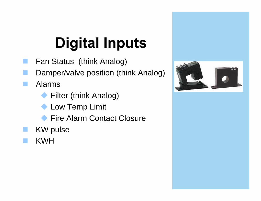
Fan Status (think Analog)Damper/valve position (think Analog)Alarms
Filter (think Analog)Low Temp LimitFire Alarm Contact Closure
KW pulseKWH

Types:GlobeBall or Characterized BallRotary segmented Plug ValveButterflyPressure independent2-way, three-way, no wayPlug characterization – linear, equal percentage
SelectionPressure drop rulesH= (GPM/Cv)2
Location within the systemRangeabilityASHRAE Research Project 1454

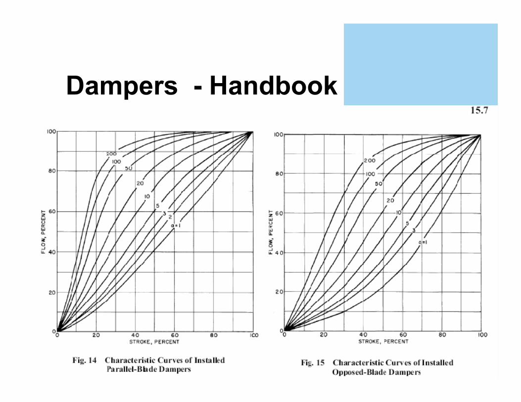
DampersTypes:
Parallel BladeOpposed BladeMixedFire - Fire/Smoke - Smoke
SelectionPressure drop curvesLocation within the systemVelocity 1000+ fpm


Selecting Outdoor, Return, and Relief Dampers for Air Side Economizer Systems
Mixing boxes don’t mixReturn dampers generally parallelOA dampers generally parallelRelief damper generally opposed blade
SelectionUses the Alpha valuesOA damper size “not Critical”
Position of device without powerNO Normally OpenNC Normally Closed
How?Spring returnBattery or capacitor
Where?Outside airSome large heating valves
Other Option ?Fail in place

Low Temp LimitManual reset1’ of element below
setpointSetpoint changes with
altitude (set higher 1º/1000 ft)
SmokeUL ListedTemp Limits
32-120Location
PressureManual reset
UL864-UUKL

BACnet LonWorks Others
ProprietaryOpenModbus
ANSI/ASHRAE 135
BTL
ANSI/EIA 709.1B
LonMark Certified
--------Standard Protocols---------
Physical Media Gateways & Routers
Transport protocol - Ethernet (ISO 8802-3)
***Don’t specify BIBs & Profiles***
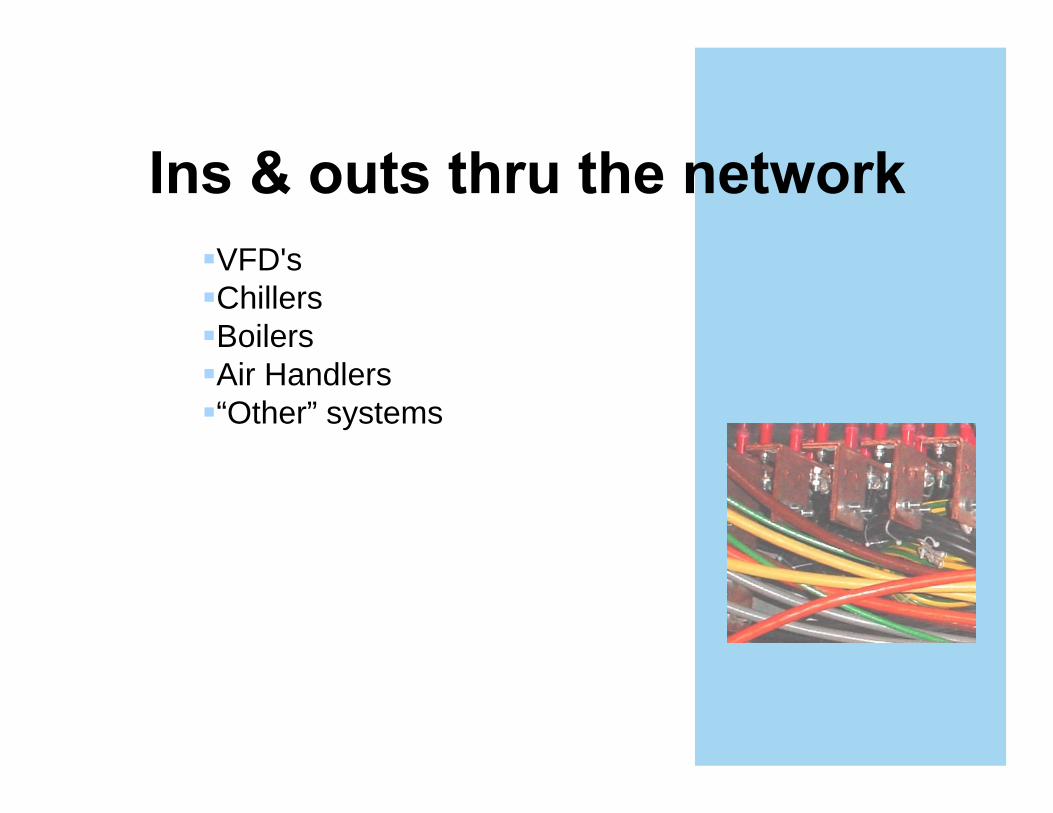
VFD'sChillersBoilersAir Handlers“Other” systems
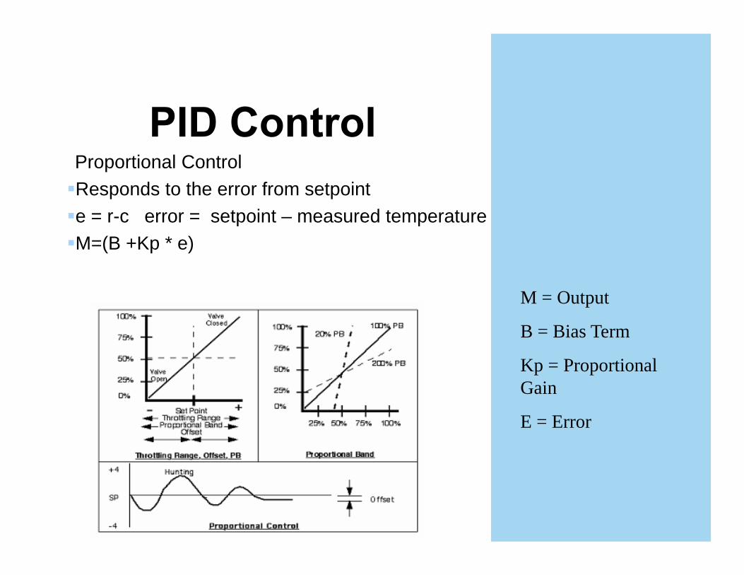
Proportional ControlResponds to the error from setpointe = r-c error = setpoint – measured temperatureM=(B +Kp * e)
M = Output
B = Bias Term
Kp = Proportional Gain
E = Error
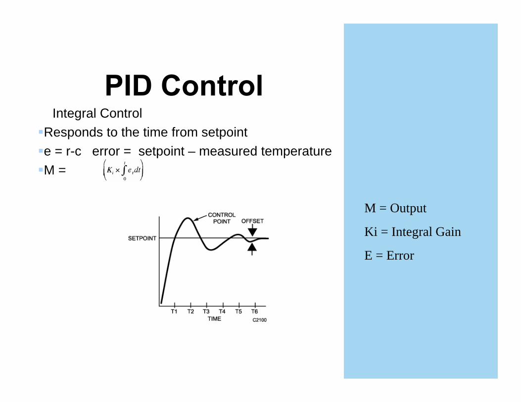
Integral ControlResponds to the time from setpointe = r-c error = setpoint – measured temperatureM =
M = Output
Ki = Integral Gain
E = Error
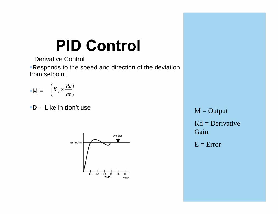
Derivative ControlResponds to the speed and direction of the deviation
from setpoint
M =
D -- Like in don’t use M = Output
Kd = Derivative Gain
E = Error
totalI+ bias
D PP
I + Bias
D
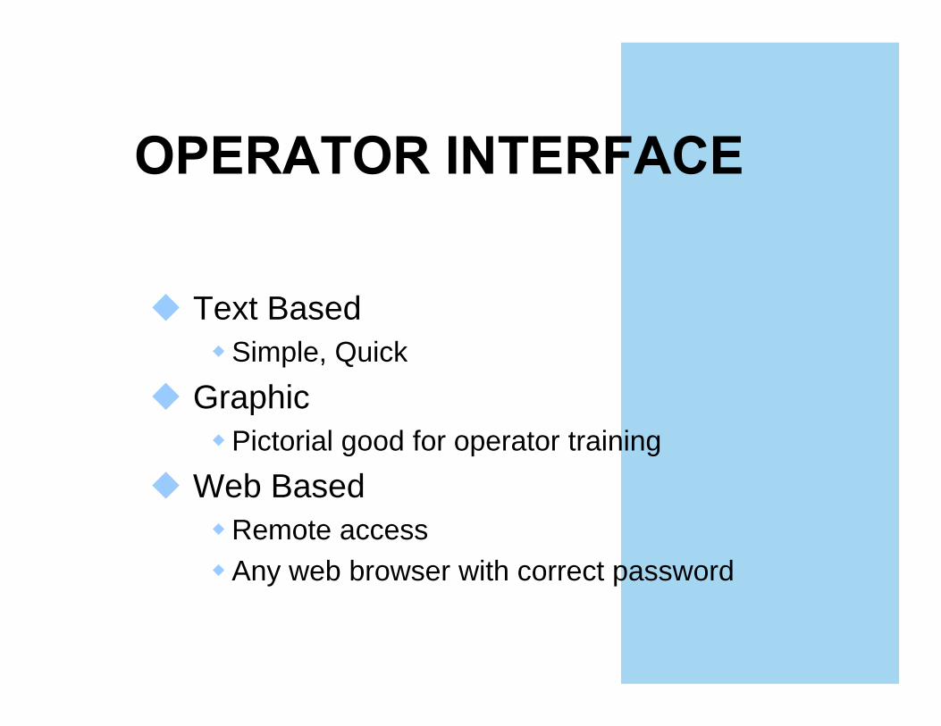
Text Based Simple, Quick
GraphicPictorial good for operator training
Web BasedRemote access Any web browser with correct password


Building controllers Larger I/O count, more powerful processor, Fully programmable
Custom application controllersMid size I/O count, medium processor, programmable or configurable, limited capacity & memory
Application specific controllers (ASCs)VAV boxes, small air handlers Configurable not programmableSmall low capacity processors
Most manufacturers support these three types of controllers with comparable functionality.

10 IF AINP1:AV > AINP2:AV THEN 20 ELSE 30(compare input 1 and 2)
20 HIGH:AV = AINP1:AV (If input 1 is high the set HIGH to equal input 1)
30 HIGH:AV = AINP2:AV (If input 2 is high the set HIGH to equal input 2)
40 IF AINP3:AV > HIGH:AV THEN 50 ELSE 60(compare input 3 to HIGH)
50 HIGH:AV = AINP3:AV (If input 3 is high the set HIGH to equal input3)
60 IF AINP4:AV > HIGH:AV THEN 70 ELSE 80(compare input 4 to HIGH)
70 HIGH:AV = AINP4:AV (If input 4 is high the set HIGH to equal input3)
80 RETURN (Start over)
Easier to learn and understandOff-line debugging Flexibility for novel or complex applicationsWho’s really going to program the system

Purpose of Guideline:Provide the new or experienced designer or developer of DDC systems including:
DDC background informationRecommendations of good practicesProject scopeDetailed discussions of options
Example specification languageExplanation of why to include featuresExplanation of components and systems
28 Air side system typesThings to considerSystem schematicObject listSequenceMode table

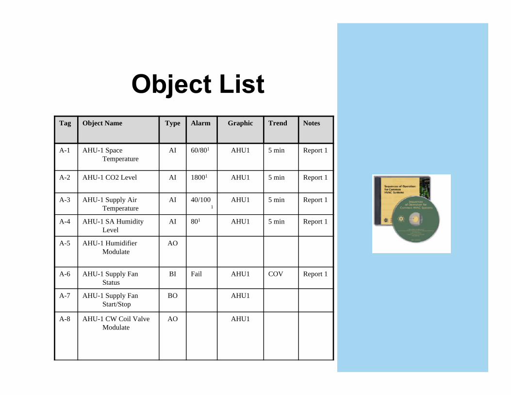
Tag Object Name Type Alarm Graphic Trend Notes
A-1 AHU-1 Space Temperature
AI 60/801 AHU1 5 min Report 1
A-2 AHU-1 CO2 Level AI 18001 AHU1 5 min Report 1
A-3 AHU-1 Supply Air Temperature
AI 40/1001
AHU1 5 min Report 1
A-4 AHU-1 SA Humidity Level
AI 801 AHU1 5 min Report 1
A-5 AHU-1 Humidifier Modulate
AO
A-6 AHU-1 Supply Fan Status
BI Fail AHU1 COV Report 1
A-7 AHU-1 Supply Fan Start/Stop
BO AHU1
A-8 AHU-1 CW Coil Valve Modulate
AO AHU1
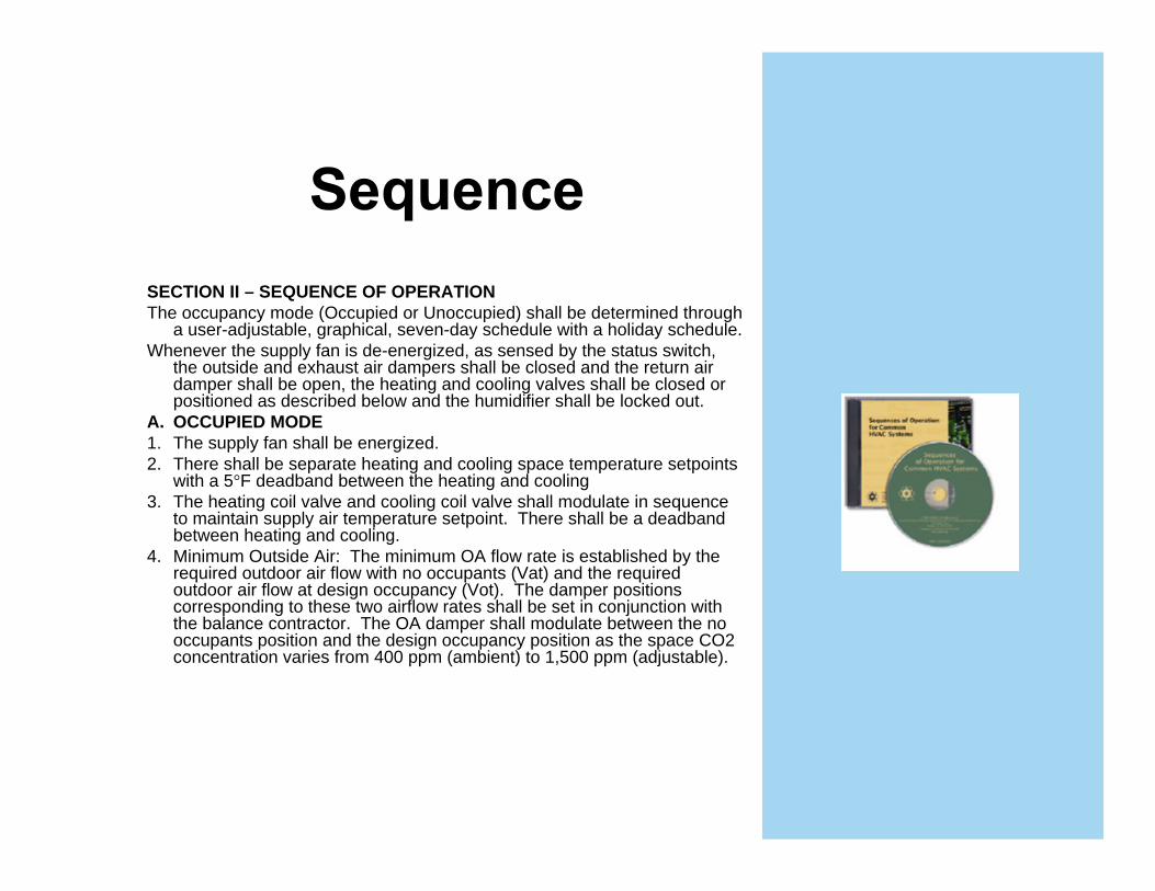
SECTION II – SEQUENCE OF OPERATIONThe occupancy mode (Occupied or Unoccupied) shall be determined through
a user-adjustable, graphical, seven-day schedule with a holiday schedule.Whenever the supply fan is de-energized, as sensed by the status switch,
the outside and exhaust air dampers shall be closed and the return air damper shall be open, the heating and cooling valves shall be closed or positioned as described below and the humidifier shall be locked out.
A. OCCUPIED MODE1. The supply fan shall be energized.2. There shall be separate heating and cooling space temperature setpoints
with a 5 F deadband between the heating and cooling3. The heating coil valve and cooling coil valve shall modulate in sequence
to maintain supply air temperature setpoint. There shall be a deadband between heating and cooling.
4. Minimum Outside Air: The minimum OA flow rate is established by the required outdoor air flow with no occupants (Vat) and the required outdoor air flow at design occupancy (Vot). The damper positions corresponding to these two airflow rates shall be set in conjunction with the balance contractor. The OA damper shall modulate between the no occupants position and the design occupancy position as the space CO2 concentration varies from 400 ppm (ambient) to 1,500 ppm (adjustable).

Device Occupied Unoccupied Safeties
Off Setback Warm-up Pre-cooling
S Fan On Off Cycles On On Off
OA Damper
Modulate to maintain CO2
setpoint subject to min position
Closed Closed Closed Closed Closed
HW Valve
Modulate in sequence with
CW valve
Cycle if OAT < 35, otherwise
closed
Modulate Modulate Closed Cycle if OAT <35,
otherwise closed
CW valve Modulate in sequence with
HW valve
Open if OAT < 35, otherwise
closed
Closed Closed Modulate Open if OAT <35,
otherwise closed
SimpleFan status & fan command mismatchLow mixed air temperature
MediumHeat valve open discharge temp low, Boiler on, pumps on
ComplexMonitor chiller data detect impending failure

InitialGet the system you paid forBase line for future operations
Retro commissioningGet back to working statusASHRAE 1137 RP commission as often as the energy savings pays back typically 3-5 years
Continuous Keep things fully functionalFine tune
ASHRAE Guideline 13ASHRAE Sequences CDBooks
Fundamentals of HVAC Direct Digital Control Frank Shadpour
DDC Online (http://www.ddc-online.org). This website details the network architecture of a core group of controls manufacturers.Automated Buildings (http://www.automatedbuildings.com/). This site is an e-zine on building automation and controls. There are a wealth of articles on a wide variety of control issues.ALI Control ClassesBe involved with ASHRAE
