datapower soa appliance service planning, implementation ... · datapower soa appliance service...
TRANSCRIPT

ibm.com/redbooks
DataPower SOA ApplianceService Planning, Implementation,and Best Practices
David ShuteDaniel Dickerson
Richard KinardManuel Carrizosa
Bruno NevesPablo SanchezByron Braswell
Service planning and optimization
Key and certificate management
Lifecycle topics
Front cover


DataPower SOA Appliance Service Planning, Implementation, and Best Practices
June 2011
International Technical Support Organization
SG24-7943-00

© Copyright International Business Machines Corporation 2011. All rights reserved.Note to U.S. Government Users Restricted Rights -- Use, duplication or disclosure restricted by GSA ADPSchedule Contract with IBM Corp.
First Edition (June 2011)
This edition applies to DataPower firmware version 3.8.2.
Note: Before using this information and the product it supports, read the information in “Notices” on page vii.

Contents
Notices . . . . . . . . . . . . . . . . . . . . . . . . . . . . . . . . . . . . . . . . . . . . . . . . . . . . . . viiTrademarks . . . . . . . . . . . . . . . . . . . . . . . . . . . . . . . . . . . . . . . . . . . . . . . . . . . viii
Preface . . . . . . . . . . . . . . . . . . . . . . . . . . . . . . . . . . . . . . . . . . . . . . . . . . . . . . . ixThe team who wrote this book . . . . . . . . . . . . . . . . . . . . . . . . . . . . . . . . . . . . . . ixNow you can become a published author, too! . . . . . . . . . . . . . . . . . . . . . . . . xiiComments welcome. . . . . . . . . . . . . . . . . . . . . . . . . . . . . . . . . . . . . . . . . . . . . xiiStay connected to IBM Redbooks . . . . . . . . . . . . . . . . . . . . . . . . . . . . . . . . . . xiii
Chapter 1. Planning. . . . . . . . . . . . . . . . . . . . . . . . . . . . . . . . . . . . . . . . . . . . . 11.1 Business framework planning . . . . . . . . . . . . . . . . . . . . . . . . . . . . . . . . . . . 21.2 Architectural map . . . . . . . . . . . . . . . . . . . . . . . . . . . . . . . . . . . . . . . . . . . . 3
1.2.1 Inclusive asset universe . . . . . . . . . . . . . . . . . . . . . . . . . . . . . . . . . . . 31.2.2 Use case scenario map. . . . . . . . . . . . . . . . . . . . . . . . . . . . . . . . . . . . 4
1.3 Base configuration items . . . . . . . . . . . . . . . . . . . . . . . . . . . . . . . . . . . . . . . 51.3.1 Hardware install . . . . . . . . . . . . . . . . . . . . . . . . . . . . . . . . . . . . . . . . . 61.3.2 Device initialization . . . . . . . . . . . . . . . . . . . . . . . . . . . . . . . . . . . . . . . 61.3.3 Network integration . . . . . . . . . . . . . . . . . . . . . . . . . . . . . . . . . . . . . . . 61.3.4 Application domains . . . . . . . . . . . . . . . . . . . . . . . . . . . . . . . . . . . . . . 71.3.5 User accounts . . . . . . . . . . . . . . . . . . . . . . . . . . . . . . . . . . . . . . . . . . . 81.3.6 Monitoring and logging . . . . . . . . . . . . . . . . . . . . . . . . . . . . . . . . . . . . 81.3.7 Configuration management. . . . . . . . . . . . . . . . . . . . . . . . . . . . . . . . . 9
1.4 Application development . . . . . . . . . . . . . . . . . . . . . . . . . . . . . . . . . . . . . . . 91.5 Life cycle phases. . . . . . . . . . . . . . . . . . . . . . . . . . . . . . . . . . . . . . . . . . . . 12
1.5.1 Revision control system . . . . . . . . . . . . . . . . . . . . . . . . . . . . . . . . . . 121.5.2 Development environment . . . . . . . . . . . . . . . . . . . . . . . . . . . . . . . . 131.5.3 Deployment packages. . . . . . . . . . . . . . . . . . . . . . . . . . . . . . . . . . . . 131.5.4 Test methodologies. . . . . . . . . . . . . . . . . . . . . . . . . . . . . . . . . . . . . . 141.5.5 Production . . . . . . . . . . . . . . . . . . . . . . . . . . . . . . . . . . . . . . . . . . . . . 15
Chapter 2. Service implementation and optimization . . . . . . . . . . . . . . . . 172.1 Multi-Protocol Gateway . . . . . . . . . . . . . . . . . . . . . . . . . . . . . . . . . . . . . . . 18
2.1.1 Gateway settings. . . . . . . . . . . . . . . . . . . . . . . . . . . . . . . . . . . . . . . . 182.2 Protocol support . . . . . . . . . . . . . . . . . . . . . . . . . . . . . . . . . . . . . . . . . . . . 19
2.2.1 File Transfer Protocol . . . . . . . . . . . . . . . . . . . . . . . . . . . . . . . . . . . . 202.2.2 MQ . . . . . . . . . . . . . . . . . . . . . . . . . . . . . . . . . . . . . . . . . . . . . . . . . . 21
2.3 Web Service Proxy . . . . . . . . . . . . . . . . . . . . . . . . . . . . . . . . . . . . . . . . . . 292.3.1 WSDL management . . . . . . . . . . . . . . . . . . . . . . . . . . . . . . . . . . . . . 302.3.2 Retrieving WSDLs. . . . . . . . . . . . . . . . . . . . . . . . . . . . . . . . . . . . . . . 33
© Copyright IBM Corp. 2011. All rights reserved. iii

2.3.3 Implementing RESTful services . . . . . . . . . . . . . . . . . . . . . . . . . . . . 342.3.4 Service versioning. . . . . . . . . . . . . . . . . . . . . . . . . . . . . . . . . . . . . . . 342.3.5 Front-Side Handlers . . . . . . . . . . . . . . . . . . . . . . . . . . . . . . . . . . . . . 352.3.6 SLM interval length agreement . . . . . . . . . . . . . . . . . . . . . . . . . . . . . 36
2.4 Web Application Firewall . . . . . . . . . . . . . . . . . . . . . . . . . . . . . . . . . . . . . . 362.4.1 Threat protection . . . . . . . . . . . . . . . . . . . . . . . . . . . . . . . . . . . . . . . . 372.4.2 Access control and security . . . . . . . . . . . . . . . . . . . . . . . . . . . . . . . 372.4.3 Content management . . . . . . . . . . . . . . . . . . . . . . . . . . . . . . . . . . . . 382.4.4 Session management . . . . . . . . . . . . . . . . . . . . . . . . . . . . . . . . . . . . 382.4.5 Best practice . . . . . . . . . . . . . . . . . . . . . . . . . . . . . . . . . . . . . . . . . . . 38
2.5 Processing policy practices . . . . . . . . . . . . . . . . . . . . . . . . . . . . . . . . . . . . 392.5.1 Authentication, Authorization, and Auditing . . . . . . . . . . . . . . . . . . . 392.5.2 Split and join processing pattern . . . . . . . . . . . . . . . . . . . . . . . . . . . . 422.5.3 Using asynchronous actions . . . . . . . . . . . . . . . . . . . . . . . . . . . . . . . 442.5.4 Minimizing memory usage . . . . . . . . . . . . . . . . . . . . . . . . . . . . . . . . 442.5.5 Open Database Connectivity (ODBC). . . . . . . . . . . . . . . . . . . . . . . . 452.5.6 Handling errors . . . . . . . . . . . . . . . . . . . . . . . . . . . . . . . . . . . . . . . . . 47
2.6 General considerations . . . . . . . . . . . . . . . . . . . . . . . . . . . . . . . . . . . . . . . 492.6.1 Service chaining . . . . . . . . . . . . . . . . . . . . . . . . . . . . . . . . . . . . . . . . 492.6.2 SOMA Execute Scripts through XML Management Interface . . . . . . 502.6.3 XML Manager . . . . . . . . . . . . . . . . . . . . . . . . . . . . . . . . . . . . . . . . . . 50
2.7 Streaming . . . . . . . . . . . . . . . . . . . . . . . . . . . . . . . . . . . . . . . . . . . . . . . . . 512.7.1 Advantages of streaming . . . . . . . . . . . . . . . . . . . . . . . . . . . . . . . . . 522.7.2 Constraints of streaming . . . . . . . . . . . . . . . . . . . . . . . . . . . . . . . . . . 522.7.3 DataPower processing actions compatibilities . . . . . . . . . . . . . . . . . 532.7.4 Streaming attachments . . . . . . . . . . . . . . . . . . . . . . . . . . . . . . . . . . . 54
Chapter 3. Managing keys and certificates. . . . . . . . . . . . . . . . . . . . . . . . . 573.1 Overview of keys and certificates . . . . . . . . . . . . . . . . . . . . . . . . . . . . . . . 583.2 Usage . . . . . . . . . . . . . . . . . . . . . . . . . . . . . . . . . . . . . . . . . . . . . . . . . . . . 58
3.2.1 Basic cryptographic components . . . . . . . . . . . . . . . . . . . . . . . . . . . 593.2.2 Hardware Security Module . . . . . . . . . . . . . . . . . . . . . . . . . . . . . . . . 613.2.3 Cryptographic tools . . . . . . . . . . . . . . . . . . . . . . . . . . . . . . . . . . . . . . 623.2.4 Certificate storage . . . . . . . . . . . . . . . . . . . . . . . . . . . . . . . . . . . . . . . 653.2.5 Key storage on a non-HSM appliance . . . . . . . . . . . . . . . . . . . . . . . 653.2.6 HSM key storage. . . . . . . . . . . . . . . . . . . . . . . . . . . . . . . . . . . . . . . . 653.2.7 Using Certificate Revocation List . . . . . . . . . . . . . . . . . . . . . . . . . . . 683.2.8 Using the Certificate Monitor . . . . . . . . . . . . . . . . . . . . . . . . . . . . . . . 69
3.3 Best practices . . . . . . . . . . . . . . . . . . . . . . . . . . . . . . . . . . . . . . . . . . . . . . 703.3.1 Managing certificates . . . . . . . . . . . . . . . . . . . . . . . . . . . . . . . . . . . . 703.3.2 Managing keys . . . . . . . . . . . . . . . . . . . . . . . . . . . . . . . . . . . . . . . . . 703.3.3 Using HSM for managing keys . . . . . . . . . . . . . . . . . . . . . . . . . . . . . 703.3.4 Import keys and change configuration to use them from HSM . . . . . 71
iv DataPower SOA Appliance Service Planning, Implementation, and Best Practices

3.3.5 Removing crypto objects. . . . . . . . . . . . . . . . . . . . . . . . . . . . . . . . . . 713.4 Examples and real-life scenarios . . . . . . . . . . . . . . . . . . . . . . . . . . . . . . . 71
3.4.1 Exporting or listing keys . . . . . . . . . . . . . . . . . . . . . . . . . . . . . . . . . . 713.4.2 Rebuilding certificate objects . . . . . . . . . . . . . . . . . . . . . . . . . . . . . . 723.4.3 Rebuilding key objects . . . . . . . . . . . . . . . . . . . . . . . . . . . . . . . . . . . 72
Chapter 4. Serviceability and Troubleshooting . . . . . . . . . . . . . . . . . . . . . 734.1 Overview . . . . . . . . . . . . . . . . . . . . . . . . . . . . . . . . . . . . . . . . . . . . . . . . . . 744.2 Benefits . . . . . . . . . . . . . . . . . . . . . . . . . . . . . . . . . . . . . . . . . . . . . . . . . . . 744.3 Usage . . . . . . . . . . . . . . . . . . . . . . . . . . . . . . . . . . . . . . . . . . . . . . . . . . . . 74
4.3.1 Monitoring and Troubleshooting . . . . . . . . . . . . . . . . . . . . . . . . . . . . 754.3.2 Viewing logs . . . . . . . . . . . . . . . . . . . . . . . . . . . . . . . . . . . . . . . . . . . 754.3.3 Latency log messages . . . . . . . . . . . . . . . . . . . . . . . . . . . . . . . . . . . 784.3.4 Error reports . . . . . . . . . . . . . . . . . . . . . . . . . . . . . . . . . . . . . . . . . . . 794.3.5 Packet Capture . . . . . . . . . . . . . . . . . . . . . . . . . . . . . . . . . . . . . . . . . 804.3.6 Probe function . . . . . . . . . . . . . . . . . . . . . . . . . . . . . . . . . . . . . . . . . . 804.3.7 XML File Capture . . . . . . . . . . . . . . . . . . . . . . . . . . . . . . . . . . . . . . . 824.3.8 Status providers and statistics . . . . . . . . . . . . . . . . . . . . . . . . . . . . . 834.3.9 Failure Notification and First Failure Data Capture (FFDC) . . . . . . . 83
4.4 Best practices . . . . . . . . . . . . . . . . . . . . . . . . . . . . . . . . . . . . . . . . . . . . . . 874.4.1 General troubleshooting . . . . . . . . . . . . . . . . . . . . . . . . . . . . . . . . . . 874.4.2 FFDC. . . . . . . . . . . . . . . . . . . . . . . . . . . . . . . . . . . . . . . . . . . . . . . . . 884.4.3 Import, export, and upgrading . . . . . . . . . . . . . . . . . . . . . . . . . . . . . . 884.4.4 Debugging AAA. . . . . . . . . . . . . . . . . . . . . . . . . . . . . . . . . . . . . . . . . 894.4.5 Debugging RBM . . . . . . . . . . . . . . . . . . . . . . . . . . . . . . . . . . . . . . . . 904.4.6 Debugging network issues . . . . . . . . . . . . . . . . . . . . . . . . . . . . . . . . 934.4.7 Debugging an unexpected restart . . . . . . . . . . . . . . . . . . . . . . . . . . . 954.4.8 Memory growth/high CPU/high load . . . . . . . . . . . . . . . . . . . . . . . . . 96
4.5 Examples. . . . . . . . . . . . . . . . . . . . . . . . . . . . . . . . . . . . . . . . . . . . . . . . . . 974.5.1 Monitoring resource growth over time. . . . . . . . . . . . . . . . . . . . . . . . 974.5.2 Example methods of isolating an issue to a particular domain . . . . . 994.5.3 Sample data collection for a failed network connection . . . . . . . . . 100
Chapter 5. Business-to-business service implementation . . . . . . . . . . . 1035.1 Introduction to B2B appliances . . . . . . . . . . . . . . . . . . . . . . . . . . . . . . . . 1045.2 B2B appliance benefits . . . . . . . . . . . . . . . . . . . . . . . . . . . . . . . . . . . . . . 1055.3 B2B appliance known limitations. . . . . . . . . . . . . . . . . . . . . . . . . . . . . . . 107
5.3.1 Application Optimization option is not available . . . . . . . . . . . . . . . 1085.3.2 The B2B Gateway Service cannot stream large files . . . . . . . . . . . 108
5.4 B2B performance testing best practices . . . . . . . . . . . . . . . . . . . . . . . . . 1085.5 Common usage patterns . . . . . . . . . . . . . . . . . . . . . . . . . . . . . . . . . . . . . 111
5.5.1 Best practices common to all patterns . . . . . . . . . . . . . . . . . . . . . . 1125.5.2 EDIINT (AS1/AS2/AS3) data exchange with data transformation. . 113
Contents v

5.5.3 Web Services bridged to AS2 . . . . . . . . . . . . . . . . . . . . . . . . . . . . . 1175.5.4 XB60 / MQ FTE integration pattern. . . . . . . . . . . . . . . . . . . . . . . . . 1195.5.5 ebMS data exchange with CPA . . . . . . . . . . . . . . . . . . . . . . . . . . . 1225.5.6 Health Level 7 clinical data exchange with standards conversion . 125
Abbreviations and acronyms . . . . . . . . . . . . . . . . . . . . . . . . . . . . . . . . . . . 129
Related publications . . . . . . . . . . . . . . . . . . . . . . . . . . . . . . . . . . . . . . . . . . 131IBM Redbooks . . . . . . . . . . . . . . . . . . . . . . . . . . . . . . . . . . . . . . . . . . . . . . . . 131Other publications . . . . . . . . . . . . . . . . . . . . . . . . . . . . . . . . . . . . . . . . . . . . . 132Online resources . . . . . . . . . . . . . . . . . . . . . . . . . . . . . . . . . . . . . . . . . . . . . . 132Help from IBM . . . . . . . . . . . . . . . . . . . . . . . . . . . . . . . . . . . . . . . . . . . . . . . . 133
Index . . . . . . . . . . . . . . . . . . . . . . . . . . . . . . . . . . . . . . . . . . . . . . . . . . . . . . . 135
vi DataPower SOA Appliance Service Planning, Implementation, and Best Practices

Notices
This information was developed for products and services offered in the U.S.A.
IBM may not offer the products, services, or features discussed in this document in other countries. Consult your local IBM representative for information on the products and services currently available in your area. Any reference to an IBM product, program, or service is not intended to state or imply that only that IBM product, program, or service may be used. Any functionally equivalent product, program, or service that does not infringe any IBM intellectual property right may be used instead. However, it is the user's responsibility to evaluate and verify the operation of any non-IBM product, program, or service.
IBM may have patents or pending patent applications covering subject matter described in this document. The furnishing of this document does not give you any license to these patents. You can send license inquiries, in writing, to: IBM Director of Licensing, IBM Corporation, North Castle Drive, Armonk, NY 10504-1785 U.S.A.
The following paragraph does not apply to the United Kingdom or any other country where such provisions are inconsistent with local law: INTERNATIONAL BUSINESS MACHINES CORPORATION PROVIDES THIS PUBLICATION "AS IS" WITHOUT WARRANTY OF ANY KIND, EITHER EXPRESS OR IMPLIED, INCLUDING, BUT NOT LIMITED TO, THE IMPLIED WARRANTIES OF NON-INFRINGEMENT, MERCHANTABILITY OR FITNESS FOR A PARTICULAR PURPOSE. Some states do not allow disclaimer of express or implied warranties in certain transactions, therefore, this statement may not apply to you.
This information could include technical inaccuracies or typographical errors. Changes are periodically made to the information herein; these changes will be incorporated in new editions of the publication. IBM may make improvements and/or changes in the product(s) and/or the program(s) described in this publication at any time without notice.
Any references in this information to non-IBM Web sites are provided for convenience only and do not in any manner serve as an endorsement of those Web sites. The materials at those Web sites are not part of the materials for this IBM product and use of those Web sites is at your own risk.
IBM may use or distribute any of the information you supply in any way it believes appropriate without incurring any obligation to you.
Information concerning non-IBM products was obtained from the suppliers of those products, their published announcements or other publicly available sources. IBM has not tested those products and cannot confirm the accuracy of performance, compatibility or any other claims related to non-IBM products. Questions on the capabilities of non-IBM products should be addressed to the suppliers of those products.
This information contains examples of data and reports used in daily business operations. To illustrate them as completely as possible, the examples include the names of individuals, companies, brands, and products. All of these names are fictitious and any similarity to the names and addresses used by an actual business enterprise is entirely coincidental.
COPYRIGHT LICENSE:
This information contains sample application programs in source language, which illustrate programming techniques on various operating platforms. You may copy, modify, and distribute these sample programs in any form without payment to IBM, for the purposes of developing, using, marketing or distributing application programs conforming to the application programming interface for the operating platform for which the sample programs are written. These examples have not been thoroughly tested under all conditions. IBM, therefore, cannot guarantee or imply reliability, serviceability, or function of these programs.
© Copyright IBM Corp. 2011. All rights reserved. vii

Trademarks
IBM, the IBM logo, and ibm.com are trademarks or registered trademarks of International Business Machines Corporation in the United States, other countries, or both. These and other IBM trademarked terms are marked on their first occurrence in this information with the appropriate symbol (® or ™), indicating US registered or common law trademarks owned by IBM at the time this information was published. Such trademarks may also be registered or common law trademarks in other countries. A current list of IBM trademarks is available on the Web at http://www.ibm.com/legal/copytrade.shtml
The following terms are trademarks of the International Business Machines Corporation in the United States, other countries, or both:
CloudBurst™DataPower device®DataPower®DB2®
IBM®IMS™Redbooks®Redbooks (logo) ®
Tivoli®WebSphere®
The following terms are trademarks of other companies:
Java, and all Java-based trademarks are trademarks of Sun Microsystems, Inc. in the United States, other countries, or both.
Microsoft, and the Windows logo are trademarks of Microsoft Corporation in the United States, other countries, or both.
Other company, product, or service names may be trademarks or service marks of others.
viii DataPower SOA Appliance Service Planning, Implementation, and Best Practices

Preface
This IBM® Redbooks® publication will help you to better understand the effective use of the WebSphere® DataPower® family of appliances. It provides guidance on the best methods identified to date for building the various components that implement solutions, such as handling MQ-based message flows or creating authentication and authorization policies. The information and recommendations in this publication are the result of real world experiences using the appliances. Such experience shows that taking the time to plan a solution implementation before beginning the work yields the greatest savings in time and energy and the highest quality outcome. This publication begins with a checklist of items to consider when planning a DataPower solution.
This publication is intended to provide answers or guidance to implementation problems often encountered by users of the appliance. This book is not intended to present complete solutions or templates because experience shows that every customer uses the appliance in their own unique environment with unique requirements. Thus, this publication provides a compendium of information about particular aspects of a solution. Use the Table of Contents or Index to find your current issue, and return to this publication when the next issue or question arises.
Refer to the related IBM Redbooks publication entitled DataPower SOA Appliance Administration, Deployment, and Best Practices, SG24-7901 for more information.
The team who wrote this book
This book was produced by a team of specialists from around the world working at the International Technical Support Organization, Raleigh Center.
© Copyright IBM Corp. 2011. All rights reserved. ix

The team - Manuel, Bruno, Gerry, Pablo, Daniel, David, Rufus, Richard, Byron
David Shute currently coordinates channel enablement activities for the DataPower family of products. He has worked in various capacities on the DataPower development staff for the past six years and entered IBM as part of the acquisition by IBM of DataPower five years ago. David has extensive experience with technical publications, technology training, and code development.
Daniel Dickerson is a Software Engineer with the IBM WebSphere DataPower SOA Appliances, CloudBurst™, and SMASH Level 2 Support Team since 2009 and with WebSphere Level 2 Support since 2006. As a Technical Support Professional, Daniel specializes in Client Technical Resolution by working directly with customers, creating knowledge sharing content, and performing lab research. His prior experience includes IBM Level 2 Support of WebSphere Application Server, IBM HTTP Server, WebSphere Edge products, and Nortel Networks as a Network Engineer. Daniel is an IBM Certified Solution Implementer for WebSphere DataPower SOA Appliances and an IBM Certified System Administrator for WebSphere Application Server Network Deployment.
Richard Kinard is the Product Manager for WebSphere DataPower Appliances. He is a subject matter expert in business-to-business technologies and has over 12 years of experience designing, developing, and implementing business-to-business solutions. He worked on many initiatives with Internet Standards Organizations to promote business-to-business interoperability and was a Senior Product Manager of a successful business-to-business application prior to working for IBM.
Manuel Carrizosa is a pre-sales support IT Specialist for Latin America at the IBM Software Sales Help center for IBM Business Partners. He has been working with the WebSphere Team since 2007. He has a degree in Systems and Computer Engineering from Los Andes University in Bogotá, Colombia. He is a certified SOA Solution Designer, WebSphere Application Server Advanced System Administrator, and a WebSphere DataPower Solution Implementer.
x DataPower SOA Appliance Service Planning, Implementation, and Best Practices

Bruno Neves is a Middleware Support Specialist at IBM Brazil. He has worked in IT since 2004 and has a mix of experiences in various fields. He has a Technologist degree in Data Processing Technology from FATEC and a postgraduate degree in SOA-based Software Engineering from Veris. His areas of expertise are WebSphere DataPower, WebSphere MQ, and WebSphere Application Server. He is an IBM Certified SOA Solution Designer and is always interested in SOA and BPM subjects.
Pablo Sanchez is an Application Integration and Middleware Support Specialist at IBM Brazil. He has worked in IT since 2003 and with WebSphere DataPower since 2007. He has a degree in Data Processing Technology from FATEC and a specialization in Computer Network from Unicamp. His area of expertise includes middleware and SOA-related technologies, such as WebSphere DataPower, WebSphere MQ, WebSphere Application Server, and WebSphere Message Broker. He is an IBM Certified for SOA, WebSphere DataPower, and MQ V7.0 System Administrator.
Byron Braswell is a Networking Professional at the ITSO, Raleigh Center. He writes extensively in the areas of networking, application integration middleware, and personal computer software. Before joining the ITSO, Byron worked in the IBM Learning Services Development in networking education development. He received a bachelor’s degree in Physics and a master’s degree in Computer Sciences from Texas A&M University.
The following author also contributed to the content and creation of this book.
Gerry Kaplan is a Senior IT Specialist with a focus on IBM WebSphere DataPower SOA appliances. He joined IBM in 2006 after more than 25 years of experience in software development and engineering. He is the author of several Redbooks publications, including the DataPower Proof of Technology book.
Thanks to the following people for their contributions to this project:
Debbie WillmschenStephen SmithLinda RobinsonTamikia BarrowShari DeianaInternational Technical Support Organization, Raleigh Center
Moses C Allotey-pappoeIBM US
Bryon KataokaiSOA Group
Preface xi

Oswaldo GagoIBM US
John RasmussenIBM US
Lingachary EswaracharyIBM US
Now you can become a published author, too!
Here's an opportunity to spotlight your skills, grow your career, and become a published author—all at the same time! Join an ITSO residency project and help write a book in your area of expertise, while honing your experience using leading-edge technologies. Your efforts will help to increase product acceptance and customer satisfaction, as you expand your network of technical contacts and relationships. Residencies run from two to six weeks in length, and you can participate either in person or as a remote resident working from your home base.
Find out more about the residency program, browse the residency index, and apply online at:
ibm.com/redbooks/residencies.html
Comments welcome
Your comments are important to us!
We want our books to be as helpful as possible. Send us your comments about this book or other IBM Redbooks publications in one of the following ways:
� Use the online Contact us review Redbooks form found at:
ibm.com/redbooks
� Send your comments in an email to:
� Mail your comments to:
IBM Corporation, International Technical Support OrganizationDept. HYTD Mail Station P0992455 South RoadPoughkeepsie, NY 12601-5400
xii DataPower SOA Appliance Service Planning, Implementation, and Best Practices

Stay connected to IBM Redbooks
� Find us on Facebook:
http://www.facebook.com/IBMRedbooks
� Follow us on Twitter:
http://twitter.com/ibmredbooks
� Look for us on LinkedIn:
http://www.linkedin.com/groups?home=&gid=2130806
� Explore new Redbooks publications, residencies, and workshops with the IBM Redbooks weekly newsletter:
https://www.redbooks.ibm.com/Redbooks.nsf/subscribe?OpenForm
� Stay current on recent Redbooks publications with RSS Feeds:
http://www.redbooks.ibm.com/rss.html
Preface xiii

xiv DataPower SOA Appliance Service Planning, Implementation, and Best Practices

Chapter 1. Planning
The DataPower device® can provide robust solutions to a wide range of enterprise needs, including, but not limited to:
� Security� Multi-Protocol Bridging� Message Content Transformation� Message Routing� Policy Enforcement� Monitoring and Logging
The flexibility of the device offers great benefits at a reduced cost of time and effort because of the configuration-driven (rather than code-driven) method of implementation offered.
This flexibility allows an enterprise to deploy a device in scenarios requiring interoperability with a wide range of enterprise assets, such as:
� Authentication systems� Databases� Mainframe applications� Diverse message transport systems� Web service applications� Web sites
1
© Copyright IBM Corp. 2011. All rights reserved. 1

In addition, the solution might require robust and reliable monitoring, logging, and error handling, which in turn might require seamless communication with another set of enterprise services, such as SNMP consoles and system logging servers.
In summary, the business requirements for any solution can easily involve a complex set of implementation requirements. For this reason, careful planning is the best way to minimize risk, ensure completeness, and contain the time and effort required to build, test, and deploy a DataPower-based solution. This chapter provides a template for the planning process from which a plan emerges.
1.1 Business framework planning
Any implementation plan must first identify the business policy or rules that will be implemented using the appliance. For example, a business policy might state any or all of the following:
� All requests from customers must contain a verifiable signature
� All responses are encrypted
� Federated identity partners must include a security assertion in all request messages
� All requests resulting in an error must be logged in full, including the contents of the message
The collection of these policies or rules can help to guide the choice of service to use to implement a solution. These rules also determine the actions taken on each message and inform such aspects as error handling.
Oftentimes a planned solution might require input and coordination among multiple enterprise stakeholders, including network operations, security, line of business managers, and more. It is a good idea to convene a meeting with all stakeholders at the early planning stages to identify requirements or gaps. For example, the business policy might require message logging, but the network infrastructure might not include a robust method to support that policy.
It is also helpful to consider the life cycle phases of the projected solution. Understanding the environments to be used for each phase, development, test and production, can inform such items as naming conventions, resource conflicts, or time lines.
2 DataPower SOA Appliance Service Planning, Implementation, and Best Practices

1.2 Architectural map
The use of an architectural map can help in understanding the elements and relationships needed to implement a given solution.
1.2.1 Inclusive asset universe
The map in Figure 1-1 depicts the many types of external resources to which DataPower can connect.
Figure 1-1 Universe of external resources
Each category of resource contains a number of specific instances. As shown in Figure 1-1, the device might connect to several types of databases, such as an IBM DB2® database, an Oracle database, a Microsoft® database, or something else.
To plan correctly for a service implementation, it is a good idea to identify the external connections needed and to what kind of system. This identification helps to guide the configuration of the device and the configuration of the networks supporting the device.
CustomPrograms
ApplicationServers
MainframesDatabaseSystems
AccessControl
SystemsRegistries
MessageTransportSystems
ConfigurationTools
LoggingSystems
MonitoringSystems
Chapter 1. Planning 3

1.2.2 Use case scenario map
The particular use case scenario might use only a subset of these services. Figure 1-2 displays a map showing the DataPower device used in two common locations:
� In the demilitarized zone (DMZ) between an enterprise and external partners, where DataPower typically performs primarily security services
� Within the enterprise as an enterprise service bus (ESB), interconnecting disparate enterprise assets in a meaningful way
Figure 1-2 DataPower use case scenarios
The map describing the services implemented on the DataPower device deployed in the DMZ is likely to be a specialized subset of the total universe of possible connections. Figure 1-3 on page 5 shows depicts security using both DataPower and Tivoli® assets.
Enterprise Secure Zone
SOAP/HTTP
WebApplication
WMB V6
(distributeevents)
DemilitarizedZone
WAS ND V6UDDI
Subscribers Publishers
WebSphereWeb services
Web servicesfor CICS
SOAP/HTTP
MQ
MQMQ
DataPowerXS40
TFIM
PartnerSOAP
DataPowerX150
(Dynamicallyroute and logWeb services)
4 DataPower SOA Appliance Service Planning, Implementation, and Best Practices

Figure 1-3 Security scenario map
You can use the device to support more than one business service. To keep the planning process simple enough to manage:
1. Create a plan for one service at a time.
2. As your plan develops, update the corresponding map.
3. As additional services are added, refer to existing plans to identify possible areas of reusability or conflict.
1.3 Base configuration items
This section presents a checklist of items to consider when initializing the device or making changes to the base configuration of the device. The settings that we review in this section affect all services running in all domains on the device. These items can only be changed in the default domain.
DataPowerXS40
Users
AMoS
Security Enforcement• Authentication• Cred. Acquisition• Authorization• Single Sign-On• Policy Enforcement• Auditing
BusinessPartners
Administrators
AccessManager
(TAM)
TAI,
LTP
A
Creds, AMBI, AMoS
JAAS, JACC, WIM
Applications
FederatedIdentity
Management (TFIM)
Chapter 1. Planning 5

1.3.1 Hardware install
Decide on the items in this list before the device is removed from the shipping container:
� Rack location
The 9235 DP device is a 1U device that includes its own rails.
� Power requirements
Use the provided power cords to connect both power supply modules to an AC power source. Connect each power supply module or the unconnected module will be reported in a failed state. The Type 9235 contains two 650-watt power modules that accept 110 or 220V current. Both power supply modules must be connected to the same power source to prevent ground voltage potential differences between the two power modules.
� Serial port
Will the serial port of the device be connected to a terminal server? If so, what is the console and port address?
1.3.2 Device initialization
In this section, we provide the initial log-in sequence:
� The initial power-up sequence requires a change to the administrator password. Decide this value and keep it in a safe place.
� Will the device be used in Common Criteria mode? If so, you must select it during initialization.
� Will it be necessary to export private keys from the device? If so, enable secure private key backup during initialization. If it is not initialized now, it will be necessary to reinitialize the device to enable this mode.
1.3.3 Network integration
In this section, we provide the network integration components:
� Ethernet interface configuration
The device offers four network interfaces in standard hardware. A minimum of one interface must be configured and activated during initial set up to accept and send network traffic. This configuration can be changed at any time after initialization.
At least one network interface must be designated to support the Web GUI or the SSHs-based command line interface. Although it is possible to run all data
6 DataPower SOA Appliance Service Planning, Implementation, and Best Practices

messaging traffic and all device administration access through the same interface(s), this is not recommended. Separating the management interface (mgmt0) from the data traffic interface allows greater control, security, and monitoring.
Decide how many Ethernet interfaces will be used, for what purpose, and also the particular properties of each, such as IP address, subnet mask, default route, static routes, and nearest gateway. All of these values affect how traffic is routed to and from the device.
� Additional network configuration
As with many network devices, values can be set for such services as DNS and NTP. VLAN addresses might also be assigned to the actual Ethernet interfaces.
Identify the appropriate values for these additional services.
� Standby Control
The Standby capability of the DataPower appliance allows one device to serve as a failover for another device. Two Ethernet interfaces on the same appliance cannot be used as members of a standby group and cannot back each other up. Ethernet interfaces on different appliances must be used as members of a standby group to back each other up.
Standby Control allows a collection of Ethernet interfaces on separate appliances to share responsibility for one virtual IP address (VIP).
This feature delivers a means to ensure high availability of services running on the devices.
1.3.4 Application domains
The device supports the creation of more than one application domain. We strongly recommend that you create at least one domain other than the default domain to hold service implementations.
Users and groups can be restricted to access only particular domains. This separation provides a good way to protect device-wide settings (such as IP address) from inadvertent changes that can disrupt all services that are running on the device and prevent collisions when more than one group of developers use the same machine.
Identify the number of domains needed to support the anticipated use of the machine. Domains can be added, altered, or deleted at any time.
Chapter 1. Planning 7

1.3.5 User accounts
When planning for the configuration of user accounts on the device, consider these requirements:
� Will full administrative access to the device be limited?
� Will authentication of users employ off-device services, such as RADIUS or LDAP? What will be the fallback user in the event that the remote authentication system fails?
� Will access be partitioned or segregated in some way, for example, network operations, application development, production monitoring? What permissions will be assigned to each group of users? What domains can groups access?
Build a table of users, groups, permissions, and access restrictions.
1.3.6 Monitoring and logging
Many enterprises employ centralized monitoring consoles to watch and maintain the health of the network. Much of the information gathered by these tools pertains to the state of the entire device, rather than specific domains or services. It is useful to plan for these connections at the time the device is deployed.
Similarly, the collection and analysis of logging information helps an enterprise understand the functioning of their network and in some cases provides information needed for regulatory agencies. It is useful to plan for the logging methods that will be used by services running on the device:
� Monitoring
The device can interact smoothly with SNMP monitoring, standard load balancer health checks, and return status information through the XML Management Interface. How will the service deliver monitoring information to external monitoring systems?
Identify the methods and information required to monitor the services running on the device and the external monitoring tools that will interact with the device.
� Logging
The device offers a range of logging options for both event and transaction-level logging. Will the device generate log information about every transaction or only for some events at some priority? Will the device move log files or log messages off the device, in what format, and at what intervals? Will log events trigger automatic actions?
8 DataPower SOA Appliance Service Planning, Implementation, and Best Practices

Identify all log information needed and the methods required to capture the desired information.
1.3.7 Configuration management
There are a number of methods available to manage the configuration of the device. The methods used can affect the configuration of the device.
� Backup and restore
How will all or part of the configuration of the device be backed up to a safe location—by hand, by automated script running on the device, or by an external entity contacting the device on a regular basis to retrieve configuration information?
In the event that a restore is needed, how will this be achieved? What connectivity or permissions will be needed?
The device can import and execute domain configurations stored on external servers. This method can help with backup and restore issues.
� Centralized management console
One or more devices can be managed from a centralized, off-device management console. Such a console requires network access to the management interface of the device and the necessary credentials.
Identify any requirements needed to support a centralized management console.
1.4 Application development
This section presents a checklist of items to consider when building a plan to implement a service on the device:
� Service Configuration by Web Services Description Language (WSDL)
Developers can configure a Web Service Proxy service using one or more WSDL files. These WSDL files can be uploaded to the device, retrieved from a remote location, or obtained from a registry, such as WebSphere Service Registry and Repository (WSRR) or a Universal Description Discovery and Integration (UDDI) instance.
Identify the method used to provide WSDL files for a Web Service Proxy service along with the required details to connect to any registry that might be used.
Chapter 1. Planning 9

� Client-side transport protocols
What protocols will the device need to support to receive or retrieve messages for processing on the client side (or front side) of the device?
List each protocol. For each protocol, include as much detail as possible, such as the need for keys and certificates to support secure connections, or the need for transactionality to support the lowest possible risk of message loss.
� Enterprise-side transport protocols
What protocols will the device need to use to send messages for processing to enterprise services? What protocols will be used to retrieve or accept responses?
List each protocol. For each protocol, include as much detail as possible, such as the need for keys and certificates to support secure connections or the need for transactionality to support the lowest possible risk of message loss.
� Authenticate/authorize connections or messages
Will the service perform authentication and authorization of requests before forwarding to enterprise services?
What methods will be employed? What information must be contained in client-side requests to enable the desired authentication or authorization system? What authority system (for example, Tivoli Access Manager or LDAP) will be used? What are the connection requirements to access that authority?
Identify all of the necessary details to implement this requirement.
� Message filtering
The device can filter messages in several ways:
– It can perform schema validation on XML messages and reject those that do not pass.
– It can perform custom filtering using a custom stylesheet.
– It can perform virus checking and filter for SQL Injection attacks.
Identify any and all forms of filtering required.
� Message-level security and integrity measures
Will the device perform security functions, such as encrypting and decrypting all or part of messages (including headers and cookies), verifying signatures, or signing messages?
Identify the security operations needed along with the cryptographic material required to support those operations.
10 DataPower SOA Appliance Service Planning, Implementation, and Best Practices

� Transform message content
Will request messages require some form of transformation before delivery to the back-end enterprise application or to ancillary supporting services, such as a database? Will response messages require transformation?
Identify the type of transformation needed, such as XML-to-XML or Binary-to-XML, for example. Identify the tools required to map out and create the necessary files to run on the device.
� Augment message content
Will the device augment messages with additional information obtained from other sources, such as a database or external file server? How will this information be obtained? What method will be used to insert this new information into the message?
Identify all tools and connections that are necessary to augment messages as needed.
� Message routing
Will the device route messages dynamically? What criteria will be used to decide appropriate routes? How will routes be assigned (a static file on the device, a stylesheet, a query of some kind)?
Identify all possible message routes and the methods used to establish those routes for each message.
� Error handling
What action will the device take when errors occur during processing? Will the transaction abort, redirect, or continue? What notification will be returned to the client? Will the action taken on error change depending on what error occurred, or will all errors be handled the same way? Is immediate notification required when some errors occur?
Identify all error handling conditions and the necessary response.
� Logging
The device offers a range of logging options for both event and transaction-level logging. Will the device generate log information about every transaction or only for some events at some priority? Will the device move log files or log messages off the device, in what format, and at what intervals? Will log events trigger automatic actions?
Identify all log information needed and the methods required to capture the desired information.
� Monitoring
Enterprises typically employ centralized monitoring methods to watch and maintain healthy systems, particularly in production environments. The device
Chapter 1. Planning 11

can interact smoothly with SNMP monitoring, standard load balancer health checks, and return status information through the XML Management Interface. How will the service deliver monitoring information to external monitoring systems?
Monitoring might also include Service Level Agreement enforcement, which can affect the flow of messages through the device.
Identify the methods and information required to monitor the services that run on the device and the external monitoring tools that will interact with the device.
1.5 Life cycle phases
As enterprises move a solution that is built on DataPower devices from purchase to production, the project passes through several distinct phases. After some time in production, the device (or devices) then age beyond the supported life span and get replaced. This entire span of activity constitutes the device life cycle.
The device life cycle typically consists of the following phases:
� Installation and initialization� User, access and domain configuration� Application development� Test� Production� Retirement
Each phase presents needs that require separate tools to meet the need. In addition, methods are needed to move a solution from one phase to the next, such as from application development to test. This movement typically requires the migration of device configurations from one machine to another or in the case of movement from test to production, from one machine to potentially many others.
In the next sections, we discuss some key areas to consider when planning for life cycle phase migrations.
1.5.1 Revision control system
Will the configurations implemented on each device be stored in a revision control system (also known as a source code control system)? If so, how will configurations move from the device where they are developed to the SCM and
12 DataPower SOA Appliance Service Planning, Implementation, and Best Practices

vice versa? Note that application domain configurations can be imported from remote locations on startup.
1.5.2 Development environment
After initial adoption and deployment of a DataPower solution, many organizations then propose and develop additional uses. In such a case, more than one developer might work on a single device. Developers might also reuse configuration assets to lower cost and time to completion. Here are some suggestions for facilitating multiple development efforts on a single device:
� Constrain each developer or team to a discreet application domain.
� Do not use the default domain for application development.
� Consider creating a single domain designed to hold reusable assets, such as stylesheets. Make this domain visible to all other domains.
� Create developer-level user accounts to prevent developers from making device-wide changes to the device, such as a VLAN address.
1.5.3 Deployment packages
The configuration import and export utilities that are available on the device allow administrators to create packages that contain configuration information about only one specific object, such as an AAA Policy, or as broad as a total system backup. Take care, then, to define in advance what constitutes a solution configuration package. Here are some examples:
� The service, such as Web Service Proxy, and all of its referenced objects, such as an XML Manager, and files, such as stylesheets:
– Allows deployment into any domain on any device
– Greater degree of containment, reducing opportunities for overwrites
– More difficult to be certain that all elements needed are included
– Allows duplicated deployment into more than one domain on a single device
� The application domain (including all services, objects and files):
– Logical unit of containment that is easily identified on any device
– Greater assurance of including all necessary elements for solution
Note: To ensure device availability, store the configuration of the default domain on the device to guarantee access during restart or reload.
Chapter 1. Planning 13

– Might contain more than one service, not necessarily only the service under development. Can also contain unwanted or orphaned objects.
� The entire device, especially including the configuration of the default domain (and thus such values as the IP addresses assigned to Ethernet ports):
– Guaranteed to include all necessary elements– No duplication on same device possible– Requires special care for default domain values such as IP addresses
The definition of a solution deployment package can in turn affect how configurations and other artifacts are stored in an SCM and what constitutes a revision.
The use of a centralized, multi-device management system can also affect how solution deployment packages are defined. These tools can support only domain-level or device-level deployments.
1.5.4 Test methodologies
The device interacts with a wide range of external services. Solutions can be designed to accept a wide range of inputs and return a range of results. It is not uncommon for the matrix of test possibilities that must be covered to be large. In addition, solutions that are destined for high volume, high load environments must undergo performance testing.
Some issues to consider when moving a solution through the test phase are:
� Will the testbed environment mirror all of the services used in the production environment?
� Does the test suite include all of the possible inputs that the solution might encounter?
� What utilities will be used to drive the load for stability and performance testing?
� How will error paths be tested?
� Is the testbed using devices that are dedicated to the test cycle?
The device provides a range of troubleshooting tools, all of which are available during the test phase. Some of these tools, such as the Probe, must not be used in a production environment because of their impact on performance. Some of these tools, such as First Failure Data Capture (FFDC), might be needed in
Note: For best results, dedicate production environment devices to production usage only.
14 DataPower SOA Appliance Service Planning, Implementation, and Best Practices

production environments as the only way to troubleshoot a problem. The test phase must include tests of these troubleshooting tools under production-like loads.
1.5.5 Production
In this phase of the life cycle, monitoring the health of the device and the services running on the device becomes most important along with robust logging.
Typically, no changes are allowed to device configuration after a solution reaches production. User accounts with the permissions necessary to make changes become few and restricted.
The reliability and frequency of backups gain importance, as does the ability to restore a configuration in the event of a disaster or other need.
Here are some areas to consider in this phase of the life cycle:
� What tools will be used to monitor the device? Are the tools tested?� What logging system will be used to capture logs?� What users with what permissions are allowed to access the device?� How will new solutions be deployed to the production environment?� How will maintenance activities be performed, such as firmware updates?
Chapter 1. Planning 15

16 DataPower SOA Appliance Service Planning, Implementation, and Best Practices

Chapter 2. Service implementation and optimization
This chapter presents a compendium of usage notes and best practices for implementing solutions using the services offered by the device.
While overview descriptions of the major services are included here, this chapter does not attempt to describe the range of capabilities presented by each service. See the official documentation Information Center at:
http://publib.boulder.ibm.com/infocenter/wsdatap/v3r8m1/index.jsp?topic=/xa35/welcome.htm
Many of the practices mentioned here apply to features that can be used in any of the services, such as an Authentication, Authorization, Auditing (AAA) Action or an SLM Policy. Some features apply only to a particular service, such as the use of WSDLs for configuration, which applies only to the Web Service Proxy. Those practices that apply only to a particular service are grouped under that service heading.
Practices related to the three major services—Multi-Protocol Gateway, Web Service Proxy and Web Application Firewall—are grouped and presented first. Practices related to features that can be used in many places then follow in an alphabetic list. Use the Table of Contents, Index, or the search ability of the reader to find information quickly.
2
© Copyright IBM Corp. 2011. All rights reserved. 17

2.1 Multi-Protocol Gateway
The Multi-Protocol Gateway is a powerful and versatile service. In additional to threat protection and multistep processing capabilities, the Multi-Protocol Gateway can process requests between various protocols. The supported protocols are HTTP, HTTPS, WebSphere MQ, WebSphere JMS, IMS™, FTP, NFS, SFTP, and TIBCO EMS.
The Multi-Protocol Gateway receives incoming requests, processes them with a processing policy, and forwards the request to the remote server. The Multi-Protocol Gateway processes the response similarly, applying the applicable response rule, if configured.
The Multi-Protocol Gateway uses Front-Side Handlers to manage client connections. A single Multi-Protocol Gateway can have multiple Front-Side Handlers that listen or poll for requests. The ability to configure multiple Front-Side Handlers allows a Multi-Protocol Gateway to receive requests from several protocols. For example, a Multi-Protocol Gateway can have one Front-Side Handler listening for HTTP requests and another handler polling a WebSphere MQ queue for messages. Both Front-Side Handlers forward the incoming message to the Multi-Protocol Gateway for processing and forwarding to the remote server.
All of the available protocols on which the Multi-Protocol Gateway can receive incoming requests can also be used on the server-side to forward the request to its destination. The client-side protocol does not need to match the server-side protocol.
A Multi-Protocol Gateway service offers many of the same services and capabilities as a Web Service Proxy service. Unlike a Web Service Proxy service, a Multi-Protocol Gateway service cannot use a WSDL to determine a configuration. A Multi-Protocol Gateway also does not automatically process and take action according to any WS-Policy attachments, as does the Web Service Proxy.
2.1.1 Gateway settings
This section provides usage notes and best practices regarding the configuration settings of the Gateway service itself, such as Response Type.
Propagate URIThis option must be turned off to support MQ-based back-end destinations.
18 DataPower SOA Appliance Service Planning, Implementation, and Best Practices

Mixed XML and Non-XML message flowsTo accommodate processing either XML or Non-XML requests to a Gateway, set the Gateway Request Type to XML:
1. Navigate to the Objects XML Processing Processing Rule page.
2. Under Non-XML Processing, click On. This allows non-XML requests to enter the Gateway processing policy without being checked for XML format automatically.
If XML-formatted messages must pass schema validation, employ a Validate action in the processing policy:
1. Set the Schema Validation Method to Validate Document via Schema URL. 2. From the SOAP Validation menu that appears, select Envelope.
The schemas to validate SOAP-formatted XML messages, including the SOAP header, can be found in the schemas:/// directory of the device, for example:
store:///schemas/soap-envelope.xsd
Implementing RESTful servicesDevelopers can implement a REST interface to standard SOAP-based Web services by configuring a Multi-Protocol Gateway to process REST-compliant requests. To support REST set the Process Messages Whose Body Is Empty value, found on the Advanced tab, to On. The default is Off.
These references detail the necessary steps:
� Implementing REST services with WebSphere DataPower SOA Appliances
http://www.ibm.com/developerworks/websphere/techjournal/0903_peterson/0903_peterson.html
� Implementing a Web 2.0 RESTful facade enabled with JSON using WebSphere DataPower SOA Appliances
http://www.ibm.com/developerworks/websphere/library/techarticles/0912_muschett/0912_muschett.html
2.2 Protocol support
This section provides usage notes and best practices regarding the configuration of the service, including Front-Side Handlers to support various transport protocols.
Chapter 2. Service implementation and optimization 19

2.2.1 File Transfer Protocol
This section addresses configuration of the File Transfer Protocol (FTP) Service.
Unique file names when writing to a FTP URL backendAlways enable the Write Unique Filename if Trailing Slash option for FTP URLs that end with a slash (/). This approach is the only safe way to have multiple systems writing files to the same directory without overwriting any files.
The Write Unique Filename if Trailing Slash settings can be found on the FTP Client Policies tab, in the User Agent settings. To find the User Agent settings, access the XML Manager settings (click “…” near it) of the service.
Limiting the port range for FTP server in passive modeThese days most company’s security policies tend to use FTP connections in passive (PASV) mode. In this mode, instead of selecting any free listening TCP port in the range 1024 to 65534, DataPower allows configuration of a restricted port range. This can be used when a firewall wants to allow incoming FTP data connections only on a limited range of ports.
The FTP Server Front-Side Handler provides an FTP server that can be used to submit files for processing by the system. When acting as an FTP server in passive mode and using the FTP Server Front-side Handler, DataPower can limit the port range used for the data connection (feature released on firmware version 3.7.2). This feature is called Limit Port Range for Passive Connections. When enabled, a lowest and highest value can be set to limit the port range that will be used on FTP connections by the DataPower.
Best practice for username:password on FTP URLWhen embedded in the URL used by the device to connect to remote FTP servers, the username and password values require special attention. The use of reserved characters (such as the ampersand character “@”) can cause the FTP logon to fail because everything following the “@” might be interpreted as the
Note: The transfer fails if the FTP server does not support the STOU command.
IMPORTANT: Because the FTP server allocates the listening ports dynamically, it is not wise to use a port range that overlaps with other services (HTTP servers, and so on) configured on the system. There is no configuration checking for such conflicts, and other configured services allocate the ports first, and they will not be available for the FTP server.
20 DataPower SOA Appliance Service Planning, Implementation, and Best Practices

server address. The username and password might also be visible on the network wire, open to capture by others.
To avoid these problems, use the Basic Auth property of the User Agent. This property is on the User Agent Configuration settings at the Basic-Auth Policy tab. Configure a policy that associates a set of URLs with a specific username and password for Basic-Auth authentication. After the username and password are set, it no longer needs to be provided in the FTP client address (for example: ftp://myserver:port rather than ftp://user:[email protected]).
File and directory listingsTo allow smooth operation with remote clients, enable LIST support on SFTP or FTP Server Front-Side Handlers. If this is not enabled, remote clients cannot identify file and directory structure information correctly. Directories will appear as files.
Furthermore, the Response Type of the Gateway in use must be set to either Non-XML or Pass-thru to allow file and directory listings to pass through the service correctly.
StreamingThe FTP-based Front-Side Handlers for a Multi-Protocol Gateway support streaming of large files under the correct circumstances. Clients connecting to a Server FSH can be authenticated using the AAA Policies configured as part of the Server Handler itself without affecting streaming.
2.2.2 MQ
This section addresses configuration of the MQ Service.
MQ headers The MQ headers are represented in DataPower as XML serialized to string. As shown in Example 2-1, the first tag is always the same as the header type, and internal tags correspond to field names.
Example 2-1 Sample of a MQMQ Header
<MQMD><MsgId>...</MsgId><CorrelId>...</CorrelId>
Note: Create a new User Agent for this purpose rather than altering the default XML Manager User Agent to avoid unintended consequences.
Chapter 2. Service implementation and optimization 21

<Format>... </Format>…</MQMD>
There are three major types of headers on DataPower: Request headers, Response headers, and Context headers:
� Request headers:
– All supported MQ headers are parsed and accessed.
– Only acted upon by the back end if needed, not by the Gateway. For example, if the request headers specify a Queue Manager, the Gateway does not attempt to place the back end Put on a queue managed by the Queue Manager named in the MQ header.
– Developers can manipulate such headers using any of the following methods:
• The header injection and header suppression inputs found on the Headers tab of the Gateway configuration
• The MQ Header processing action
• The extension functions “dp:set-request-header” or its alias “dp:set-http-request-header”
– On incoming messages, headers can be stripped accordingly by the MQ Front-Side Handler Exclude Message Headers setting.
� Response headers:
– Used by the MQ FSH for sending responses back after processing response rule policies.
– Developers can manipulate such headers using any of the following methods:
• The header injection and header suppression inputs found on the Headers tab of the Gateway configuration
• The MQ Header processing action
– The extension functions “dp:set-response-header” or its alias “dp:set-http-response-header”
– By default, the MQMD header is removed from the payload. All the others remain due to backward compatibility with previous versions of the firmware.
– Use the dpmq:// URL query parameter ParseHeaders=true to exclude all headers from the response payload.
22 DataPower SOA Appliance Service Planning, Implementation, and Best Practices

� Context headers:
– Every context has its own request and response headers
– Set headers using the extension function dp:set-variable(); for example “var://context/<CONTEXT_NAME>/_extension/header/<HEADER_NAME”>
– It is possible to read response headers using “var://context/<CONTEXT_NAME>/_extension/responseheader/<HEADER_NAME>”
Important MQ header recommendations� When injecting MQMD.ReplyQ using the Header Injection method, do not use
the setReplyTo=true tag in the back end MQ URL. If you use both, the value for MQMD.ReplyQ that is set by the Header injection method is overwritten with the value used in the URL “ReplyQueue” parameter.
� When injecting headers related to “identity context” or “origin context”, DataPower does not modify these headers if correct PUT Message Options (PMO) are not specified in the MQ URL. For setting the “identity” MQMD headers (UserIdentifier, AccountingToken, ApplIdentityData), use a “PMO=1024” (MQPMO_SET_IDENTITY_CONTEXT) for the back end MQ URL. Further, to set “origin” MQMD headers (PutApplType, PutApplName, PutDate, PutTime), use PMO=2048 (MQPMO_SET_ALL_CONTEXT) along with other PMO values if needed for the backend MQ URL.
For injecting headers related to identity context with Units-of-work being set in the mq-qm object, use the following MQ URL:
dpmq://qmgr-object/?RequestQueue=QUEUE1;ReplyQueue=QUEUE3;PMO=1026 (MQPMO_SET_IDENTITY_CONTEXT + MQPMO_SYNCPOINT)
For injecting headers related to identity context without Units-of-work being set in mq-qm object, use the following MQ URL:
dpmq://qmgr-object/?RequestQueue=QUEUE1;ReplyQueue=QUEUE3;PMO=1024 (MQPMO_SET_IDENTITY_CONTEXT)
For injecting headers related to origin context with Units-of-work being set in the mq-qm object, use the following MQ URL:
dpmq://qmgr-object/?RequestQueue=QUEUE1;ReplyQueue=QUEUE3;PMO=2050 (MQPMO_SET_ALL_CONTEXT + MQPMO_SYNCPOINT)
For injecting headers related to origin context without Units-of-work being set in mq-qm object, use the following MQ URL:
dpmq://qmgr-object/?RequestQueue=QUEUE1;ReplyQueue=QUEUE3;PMO=2048 (MQPMO_SET_ALL_CONTEXT)
Chapter 2. Service implementation and optimization 23

� When the request message contains values for the MQMD.ReplyQ and MQMD.ReplyToQMgr that are not configured in the MPGW service, DataPower routes the message based on these values. To route the message to the correct destination, the service virtual headers must be set to empty string by using the stylesheet method, for example:
<dp:set-response-header name="'ReplyToQ'" value="' '"/><dp:set-response-header name="'ReplyToQM'" value="' '"/>
This does not work if the Headers tab is used.
Controlling connection retriesThe MQ Queue Manager object provides the ability to set retry settings, such as the Retry Interval, Retry Attempts, and Long Retry Interval parameters. These settings specify how DataPower behaves when having connectivity issues with the remote Queue Manager.
If the value of Retry Attempts is set to 0 on the MQ Queue Manager object, DataPower retries forever using the specified Retry Interval. To control this behavior and lessen resource consumption when the remote Queue Manager becomes unavailable, change the Retry Attempts parameter to some number greater than 0 (zero). As an example, change the parameters as follows:
� Retry Attempts: Change from the default of 0 to 6
� Retry Interval: Change from the default of 1 to 10 seconds
� Long Retry Interval: Change from the default of 1800 to 600 seconds (10 minutes)
In the event that the Queue Manager is down or a connection is not established, this example configuration allows the MQ QM Object to retry six times with 10 second intervals. After six attempts, the MQ QM object retries every 10 minutes.
Controlling MQ Queue Manager connection poolsAn MQ Queue Manager object has a Total Connections Limit property that specifies the total number of allowed open connections to the specified remote Queue Manager. This pool limit is shared among all connections, front side or back side, that use this Queue Manager instance. The default value is 250, and the maximum allowed value is 5000.
An MQ Front-Side Handler, in turn, offers a Concurrent Connections property. Set this number lower than the Total Connections Limit of the Queue Manager that is used by the Front-Side Handler. If more than one Front-Side Handler uses the same Queue Manager object, and all are consistently active Handlers, the sum total of the Handler Concurrent Connections must not exceed the Total Connections Limit.
24 DataPower SOA Appliance Service Planning, Implementation, and Best Practices

The Queue Manager Total Connections Limit also affects any connections established to the back end queue if the Queue Manager is used for those connections. If a Queue Manager does handle both front and back side connections, the number of Concurrent Connections allowed for the front side must be low enough to allow the desired availability of back side connections. Note that if a different Queue Manager is used for front and back, this connection balancing is not necessary.
The total number of open connections at any time is affected by the Queue Manager cache timeout value. See the next section for more information about the cache timeout.
Controlling idle connectionsSometimes a burst of requests ramp up the number of connections of the MQ Queue Manager object. Many of the connections remain idle after the burst of requests are processed. To minimize the number of open idle connections, set the Cache Timeout property on the MQ Queue Manager object to some value so that the idle connections are closed after this timeout elapses. For best results, set the Cache Timeout to a value that is larger than the negotiated Channel Heartbeat and smaller than the Keep Alive Interval on the remote MQ server.
Controlling waiting connectionsTo control the number of connections waiting for a reply to appear on the specified ResponseQueue, set the Timeout parameter of the MQ URL used to determine the back end destination to a small but reasonable value.
Managing Front Side message retrievalAn MQ Front-Side Handler automatically polls the remote queue and retrieves any available messages. In the event that transactionality is enabled on the Front Side (Queue Manager Units of Work = 1) and a transaction rolls back for any reason, the request message again becomes available on the front side queue. To prevent what might be an infinite loop, enable the Automatic Backout on the Queue Manager object configuration of the device. Set a Backout Threshold (the number of times a message will be retrieved) to stop the Front-Side Handler from retrieving the same message again. Set the Backout Queue Name to automatically remove the message from the GET queue and place it elsewhere. This mechanism makes it easy for administrators to identify problem messages.
Note: By default, the Cache Timeout has a value of empty string that does not close idle connections.
Chapter 2. Service implementation and optimization 25

Handling large messagesWhen configuring a service to handle large messages flowing through an MQ messaging system, developers might need to set the Maximum Message Size parameter of the MQ Queue Manager object to a new and larger value. When this number is increased, check the XML Bytes Scanned value that is set on the XML Parser tab of the XML Manager in use by the Gateway that is handling the traffic. Make sure that the XML Bytes Scanned value is equal to or larger than the Maximum Message Size of the Queue Manager. Adjusting the XML Manager value is not required for non-XML content.
In addition, check the size of messages that the remote Queue Manager channel and queues allow.
In cases where some messages might be large yet most smaller, consider using a separate Queue Manager for the large message traffic.
Minimizing MQ Front-Side Handler instancesAs a rule, use the fewest number of MQ Front-Side Handlers attached to a single Gateway as possible to minimize potential disruptions when the configuration of any Handler or the Gateway itself changes.
Dynamic queuesUse temporary dynamic queues whenever possible to conserve resources because temporary queues are deleted automatically when usage completes.
Prefer static to dynamic MQ URLUsing the dpmq:// style of URL is preferable to the mq:// style of the MQ URL. Only use dynamic MQ URL for really ad hoc MQ connections.
Queue manager failoverUse Queue Manager groups in MQ Front-Side Handlers or MQ URLs to implement failover between primary and standby MQ Queue Managers. This is the preferred way to connect to multi-instance queue managers.
Note: When the Units of Work is set to “1” and a custom error rule is being used in the policy, var://service/error-ignore must be set to “1” to handle message roll back in the error rule.
Note: Start by checking the MQQM object and the XML Manager message size properties when DataPower is showing a MQRC 2010 error for large messages transfer attempts.
26 DataPower SOA Appliance Service Planning, Implementation, and Best Practices

Using the Sync parameterUse the Sync parameter for transactional MQ URL (Sync=true;Transactional=true) for Request/Response message flow. The Sync parameter is used to commit the request to the RequestQueue of the MQ URL, as such, the back-end application can access the request. Prepare the response, and send the message to ReplyQueue. Request/Reply MQ URL with only Transactional=true will always timeout and fail in getting the reply.
MQ single-phase COMMITDataPower supports one phase COMMIT. To support this feature, the following conditions must be true:
� The same MQ Queue Manager must be used in the MQ Front-Side Handlers and any MQ URLs, including the back end destination.
� All processing actions must be synchronous.
� The same connection is shared across all MQ operations within a transaction.
Follow these guidelines to implement “once-and-only-once” message delivery.
Handling MQ return codes (MQRC)In some cases, clients want the MQ error code returned by the device when an MQ-level error occurs. By default, the device returns its own error message that omits the MQ error code. To return an MQ-specific error message:
Use a response rule to capture the response code by using the style sheet code snippet, as shown on Example 2-2.
Example 2-2 Example of MQ error handling style sheet code
<xsl:variable name="mqrc" select="dp:response-header('x-dp-response-code')"/><xsl:variable name="ecode" select="dp:variable('var://service/error-code')"/>
<xsl:choose><xsl:when test="(starts-with($mqrc, '2') and (string-length(normalize-space($mqrc))= 4)) or ($ecode != '0x00000000')">
<dp:xreject reason="'MQ Error'" override="true"/></xsl:when><xsl:otherwise>
<dp:accept/></xsl:otherwise>
</xsl:choose>
Chapter 2. Service implementation and optimization 27

Because the device is processing Backend Errors, turn “Process Backend Errors” on when custom error processing is configured.
Handling errorsFor handling MQ errors, use a response rule to capture the response code by using the code snippet as follows:
<xsl:variable name="mqrc" select="dp:response-header('x-dp-response-code')"/> <xsl:variable name="ecode" select="dp:variable('var://service/error-code')"/> <xsl:choose> <xsl:when test="(starts-with($mqrc, '2') and (string-length(normalize-space($mqrc))= 4)) or ($ecode != '0x00000000')"> <dp:xreject reason="'MQ Error'" override="true"/> </xsl:when> <xsl:otherwise> <dp:accept/> </xsl:otherwise> </xsl:choose>
Because the device is processing “Backend Errors”, turn “Process Backend Errors” on when custom error processing is configured.
When Units of Work is set to “1”, the appliance rolls back a message to its configured Backout queue, if it cannot deliver to the destination queue. The error conditions are handled by the device.
However, if you want to handle the error conditions using an error rule, the device has to COMMIT the transaction after the MQ PUT is done. To do this, set the variable “var://service/error-ignore” to “1” in the error rule to make sure that the transaction is committed when the message is PUT to an alternate queue, not to the Backout queue.
Further, the MQ URL must contain the “Sync=true” tag that allows the queue manager to COMMIT immediately after the MQ PUT is done. If the “Sync=true” tag is not used, there can be uncommitted message(s) in the alternate queue. Here is an example of using the MQ URL in the error rule:
dpmq://qmgr-object/?RequestQueue=QUEUE4;Sync=true
Note: For Datagram traffic, set “Process Backend Errors = off” if the processing policy is not handling MQ errors. This “Process Backend Errors” field is visible under the MPGW's advanced tab.
28 DataPower SOA Appliance Service Planning, Implementation, and Best Practices

Datagram messages with distribution listsMQ Distribution Lists provide an optimal way of fanning out messages when the same message is required to be distributed to multiple destination queues. This can be accomplished on DataPower by injecting a MQOD request header with multiple destination queues, as shown on Example 2-3.
Example 2-3 MQOD header example for distribution list
<MQOD><MQOR><ObjectName>Queue1</ObjectName></MQOR><MQOR><ObjectName>Queue2</ObjectName></MQOR><MQOR><ObjectName>Queue3</ObjectName></MQOR><MQOR><ObjectName>Queue4</ObjectName></MQOR>
</MQOD>
Using this approach, performance increases significantly and four separate calls become a single one. To inject MQOD headers for the back end MQ Queue Manager, use DataPower's extension function <dp:set-request-header name=”MQOD” value="$mqodStr"/> in the custom style sheet or MPGW's Header injection tab.
2.3 Web Service Proxy
The Web Service Proxy provides security and abstraction for remote Web services. By loading a WSDL file and adding a Front-Side Handler, a Web Service Proxy is ready to start receiving requests. Although this configuration is simplistic, it is a fully functioning, feature-rich service that provides endpoint/URI abstraction, parser-based XML threat protection, XML well-formed checking, SOAP schema validation, payload schema validation, hooks for monitoring, and a platform for building operation-level rules.
The WSDL file provides critical information about a Web service, including endpoint locations, instruction on binding to these endpoints, and expected message schemas. With just the WSDL and a Front-Side Handler, a Web Service Proxy has the basic configuration. Additional configuration can be defined to meet your case requirements, such as AAA, document transformations, message encryption, and so forth.
In addition to the Web Service Proxy being able to upload or fetch a WSDL file, the configuration of a Web Service Proxy can be through a subscription to a UDDI registry or WSRR server. Through subscription, the Web Service Proxy receives automatic updates of the WSDL file or dynamically looks up the endpoints for the service.
Chapter 2. Service implementation and optimization 29

The Web Service Proxy has powerful monitoring and logging capabilities. Web services traffic that flows through a Web Service Proxy can be monitored and logged at the service level down to the WSDL operation level. Other features of a Web Service Proxy are service-level monitoring (SLM), WS-ReliableMessaging, WS-Policy, and WS-Addressing.
2.3.1 WSDL management
Developers create a Web Service Proxy by providing one or more Web Services Description Language (WSDL) files for the Proxy service to parse and use as the basis for the various elements of the service. Management of the WSDL files on which the service is based is a key element of managing a WSP. This section discusses some of the usage considerations and best practices regarding WSDL management.
UDDI subscriptionsAnother way to configure a WSP service is to retrieve the WSLD document from an Universal Description Discovery and Integration (UDDI) repository. The documentation of what is needed to configure a UDDI subscription is at the following URL:
� DataPower configuration with UDDI: http://www-01.ibm.com/support/docview.wss?uid=swg21329054
WebSphere Registry and Repository subscriptionsA Web Service Proxy pulls the WSDL document of a service from WebSphere Service Registry and Repository (WSRR), if so configured. The following list describes the subscription options when retrieving a WSDL document from WSRR:
� Subscribe to an individual WSDL: The WSP polls the WSRR server and updates the WSP service when the WSDL that is in WSRR changes.
� Subscribe to a WSRR Concept: Subscribing to a concept makes it possible to dynamically subscribe to a group of WSDLs rather than one at a time. It is important to understand that only one WSDL is pulled each time and the device can only pull WSDL documents.
� Employ a search saved on the WSRR server to locate and select a particular WSDL (available in firmware 3.8.1 and later). This provides a means to select a WSDL dynamically.
The use of a WSRR registry as the source of WSDL documents offers a number of benefits:
� The registry provides a centralized, managed store for WSDL documents.
30 DataPower SOA Appliance Service Planning, Implementation, and Best Practices

� Polling eliminates the need to manually alter the device configuration.
� Search queries enable dynamic WSDL selection and thus dynamic Proxy configuration control.
� WSDLs can easily be versioned, allowing for smooth evolution of services
Here are some general considerations for using WSRR subscriptions to obtain WSDL files:
� Use “Saved Search” subscriptions when “loose coupling” is required between the device and WSRR regarding which web services are being proxied by the device.
� Use “Concept” for a similar use case as previously described, but using “Concept” tags instead of a named WSRR query.
� Use “WSDL” for “tight coupling” of the device and WSRR registry information regarding which web service to proxy. This selection allows only one WSDL per subscription.
� Use “Polling” as the default synchronization method to eliminate the need for manual intervention.
� The polling cycle time must be tuned depending on factors such as: (1) frequency of changes to WSRR registry, (2) frequency of desired change because the customer might decide that one time a week is good enough to roll out new service updates, (3) expected appliance load, and (4) governance requirements (this might also force the synchronization method to be manual).
� Use the WSRR governance process, which associates Governance states to registry objects, to force (or prevent) the device from proxying published web services, for example:
– Create a Concept tag called “PublishToGW” and only mark those WSDLs desired with that tag to make them visible to the device.
– Create a WSRR query that performs some arbitrary matching of object name/version/classification/govern state, and save that query as a “Saved Search” in WSRR. On the device, configure a proxy to use the saved search, making it possible to manage published and available web services through their life cycles using WSRR rather than the device.
� The device logs all poll that result in retrieving 0 WSDLI(s) as an error in the logging system. If this occurs, check the spelling of the WSDL or Concept or saved search name. Changes might be required on the WSRR side as well.
� If the issue is on the WSRR side, correct the problem in the WSRR registry and manually force a synchronization between the device and the registry. To force a synchronization, select Status Web Service WSRR WSRR Subscription Service Status, and click Synchronize.
Chapter 2. Service implementation and optimization 31

� Note that the credentials used in the WSRR Saved Search object on the device must be the same as those used to create the WSRR Saved Search on the WSRR server.
The following IBM RedPapers explain the benefits of WSRR subscriptions and the detailed steps to configure a subscription to a WSRR concept:
� IBM WebSphere DataPower SOA Appliances Part IV: Management and Governance, REDP-4366
� Integrating WebSphere Service Registry and Repository with WebSphere DataPower, REDP-4559
Caching WSDLsThe WSDL Cache Policy of the Web Service Proxy service controls how often a WSDL is automatically refreshed. The WSDL Cache Policy is accessible through the WebGUI main navigation bar under Objects Services Web Service Proxy.
Select the appropriate WSP object and the WSDL Cache Policy tab. The following fields are available to configure the caching policy:
� URL Match Expression that is used to specify the WSDL� The Time to Live (TTL) in seconds as the refresh interval
The caching policy configured for a WSDL document also applies to the schema files referenced by the WSDL document and other schemas referenced in turn by those files.
For WSDL documents stored in UDDI, subscription notification is supported, so it is not necessary to set a caching policy:
� When using WSRR, the cache policy is set by configuring the refresh interval in the WSRR subscription parameters.
� WSDLs retrieved from WSRR are cached; however, the cache timeout value does not apply. If the WSRR server becomes unavailable and the device remains active, the WSDLs retrieved from WSRR remain available through the cache. They are not updated.
Caching policy: The caching policy is only available for WSDL documents that are hosted outside the appliance. The caching policy does not apply when the WSDL document is stored in the device file system or in an external repository, such as UDDI or WSRR.
32 DataPower SOA Appliance Service Planning, Implementation, and Best Practices

Using the same WSDL with multiple Web Service ProxiesDuring the development life cycle, developers can create more than one Web Service Proxy that uses the same WSDL file for configuration. This might happen while a solution transitions from development to test or from test to production.
Although the Proxy services can be in different application domains, such a configuration causes certain configuration properties, such as the Front-Side Handler port and URI to be linked.
Replacing or updating a WSDLWhen updating or replacing a WSDL document for a WPS service, detach the WSDL from the WSP and then attach it again. This process ensures the compilation of the new WSDL. It is always a good practice to test if the new WSDL is compiled.
WSDL import statementsA WSDL used by a WSP can in turn import other WSDL documents or schema files. The WSP does automatically follow these references and import the identified objects as long as the device has access to the URL used for the import. If these artifacts all reside on the device file system, relative references work. If these artifacts reside outside of the device, absolute references might be required.
In either case, the URL must not exceed 128 characters.
2.3.2 Retrieving WSDLs
To retrieve a WSDL from a WSP service, the GET method in the HTTP or HTTPS Front-Side Handler must be allowed. The syntax to retrieve the WSDL is the URL of the service including “?wsdl” at the end of the address. For example the following URL can be use to retrieve a WSDL document: http://service:port/uri?wsdl
Note: When using one WSDL to configure multiple WSP services in the same or different domains, set a unique local Ethernet address for each one of the WSDL documents. This is done by creating a separate FSH for each one of the configured WSDL documents.
Note: To maximize the availability of your services upon restart, be sure to set the automatic retry option that is under the appropriate Web Service Proxy service configuration in the appliance objects. This way, even if the device fails to retrieve the remote attachments and references on the initial try, it will retry.
Chapter 2. Service implementation and optimization 33

Example 2-4 reflects the Endpoint Policy Subjects that can be shown using the “?wsdl” query.
Example 2-4 Endpoint Policy Subjects shown by the WSP
wsdl:service -> wsdl:port wsdl:service -> wsdl:port -> wsdl:binding wsdl:service -> wsdl:port -> wsdl:binding -> wsdl:portType
In all three cases, the ?wsdl command returns the merged policy attached to the port, not the binding or the portType.
The ?wsdl command does not return what is actually in the WSDL document, but rather the compiled version of it, modified to reflect the service that the client sees based on all of the configuration information associated with the WSP service.
2.3.3 Implementing RESTful services
Developers can implement a REST interface to standard SOAP-based Web services by placing either an XML Firewall service or a Multi-Protocol Gateway service in front of a Web Service Proxy that is configured by WSDL. These references detail the necessary steps:
� Implementing REST services with WebSphere DataPower SOA Appliances
http://www.ibm.com/developerworks/websphere/techjournal/0903_peterson/0903_peterson.html
� Implementing a Web 2.0 RESTful facade enabled with JSON using WebSphere DataPower SOA Appliances
http://www.ibm.com/developerworks/websphere/library/techarticles/0912_muschett/0912_muschett.html
2.3.4 Service versioning
It is not unusual for a back end service to evolve and change over time. To facilitate this kind of change, an organization might want to support both the existing and the newer versions of the service while consumers adapt to changes. This scenario might require a Web Service Proxy to employ two
Note: The "?wsdl” query reflects the actual (merged) behavior of the Web Service Proxy, not the original wsdl and the original configuration,
34 DataPower SOA Appliance Service Planning, Implementation, and Best Practices

versions of a WSDL simultaneously. This is easily done as long as the following two conditions are met:
1. Use a different target namespace for each WSDL version. The following code shows the namespace tag in a WSDL document.
Example 2-5 Unique Target Namespace
<?xml version="1.0" encoding="UTF-8"?><wsdl:definitions xmlns:wsdl="http://schemas.xmlsoap.org/wsdl/" xmlns:soap="http://schemas.xmlsoap.org/wsdl/soap/" xmlns:http="http://schemas.xmlsoap.org/wsdl/http/" xmlns:xs="http://www.w3.org/2001/XMLSchema" xmlns:soapenc="http://schemas.xmlsoap.org/soap/encoding/" xmlns:tns="https://www.payment.com/Order.1.1/" targetNamespace="https://www.payment.com/Order.1.1/">
<wsdl:types><xs:schema
targetNamespace="https://www.payment.com/Order.1.1/" xmlns:xs="http://www.w3.org/2001/XMLSchema" xmlns:tns="https://www.payment.com/Order.1.1/" elementFormDefault="qualified">
2. Use different local URIs for each service version. Figure 2-1 shows the local URI in the WSDL configuration window.
Figure 2-1 Setting the local URI
It is possible to change the port rather than the URI that is bound to one of the WSDLs. Changing the port value requires creating a new Front-Side Handler.
2.3.5 Front-Side Handlers
A Web Service Proxy must employ at least one Front-Side Handler to accept incoming requests. The Proxy supports the use of more than one Front-Side Handler, such as in the case where a Proxy both receives HTTP requests and polls an MQ Queue for requests.
Chapter 2. Service implementation and optimization 35

The Front-Side Handler can employ any transport protocol, allowing enterprises to expose WSDL-described HTTP-based back end services to clients employing other transport protocols. This can be done using a Multi-Protocol Gateway as well but only a Web Service Proxy offers configuration by WSDL.
More than one Web Service Proxy can use the same Front-Side Handler. This configuration makes it possible to publish a single Internet Address and port number to support a larger range of services split across more than one Web Service Proxy. Using a unique URI for each service provides separation of services for tracking and debugging purposes.
2.3.6 SLM interval length agreement
An SLM Policy allows administrators to set a threshold interval (such as no more than x requests each second) set on the SLM Policy Statements page.
When an SLM policy is being enforced by more than one device, administrators must also set a SLM Update Interval on the SLM tab of the XML Management Interface configuration page found only in the default domain.
The SLM Update Interval must be equal to or less than the threshold interval set in any SLM Policy statement in use on the device. If not, the updates deliver outdated information to the individual policies and are ignored, defeating the purpose of peering.
2.4 Web Application Firewall
The Web Application Firewall service offers unique features designed to proxy and protect HTML and XML-based web applications. A common use of a Web Application Firewall is to provide perimeter authentication for web applications, asserting the user’s identity to the remote application server in a format that the application server can consume. For example, a Web Application Firewall can authenticate the user with the credentials in the request using HTTP basic authentication and create an LTPA token that can propagate the identity to a remote application server.
36 DataPower SOA Appliance Service Planning, Implementation, and Best Practices

2.4.1 Threat protection
The list of threat protections offered by the device includes defenses against the main techniques used by attackers to explore weaknesses found in web applications:
� XML threats
Covers XML Entity Expansion and Recursion Attacks, XML Wellformedness-based Parser Attacks, XML Flood, XPath/XSLT Injection Attack, XML Virus, XML Encapsulation, XML External Entity (XXE) Attack, and so forth.
� SQL injection
Protection against SQL injection codes passed through HTML forms.
� Dictionary attack
Protects from automated processes using dictionaries to get into the system.
� Cookie security management
Encrypts, decrypts, signs, and cookies.
� Cross-site scripting
Protects against cross-site scripting (XSS) attacks.
� Rate limits
Limits the number of transactions per client handled by the device for each WAF object.
2.4.2 Access control and security
The Web Application Firewall includes all of the standard features of the DataPower Authentication, Authorization, Auditing (AAA) processing capabilities, allowing the service to authenticate and authorize requests on behalf of the web application, offloading processing cycles and protecting the web application from malicious attack. The Firewall can change tokens from a format preferred by outside partners to one required by the back end system.
In addition, all of the standard benefits of a proxy apply. Clients do not access the web service directly, obscuring its location.
This combination of capabilities provides excellent perimeter security. The appliance can reside in the DMZ while the application server can reside safely behind corporate firewalls.
Chapter 2. Service implementation and optimization 37

Figure 2-2 demonstrates how the device can be deployed to make use of the perimeter security.
Figure 2-2 Example of perimeter security implementation
2.4.3 Content management
The Web Application Firewall provides easy ability to inspect and filter HTTP headers and query strings and HTML form-based input through the use of name-value pairs. This includes protection against cross-site scripting attacks.
2.4.4 Session management
The Firewall session management establishes a series of start pages that the protected application uses as initial browsing points or landing pages. A client request to access these pages causes the firewall to issue a signed and time limited cookie which must be presented to access any pages not designated as a starting point. This offloads the need to restrict initial access to only designated pages and track session length on behalf of the application.
2.4.5 Best practice
The Web Application Firewall provides easy-to-configure methods for providing the following services, which make the Web Application Firewall an excellent choice for the proxy and protection of web applications. Consider this service if any of these are primary requirements:
� Support all HTTP Methods� HTML Forms Content Filtering Including XSS and SQL Injection
Internet
DMZ Trusted Network
DataPower
DataPower
ApplicationServer
ApplicationServer
ApplicationServer
ApplicationServer
LoadBalancer
38 DataPower SOA Appliance Service Planning, Implementation, and Best Practices

� Query String Protection� Cookie Content Filtering and Protection� Handle Mixed XML and HTML Forms Submissions� Enforce Authentication and Authorization Policies Across Token Types
2.5 Processing policy practices
All services employ a processing policy. The construction of the policy significantly affects the efficiency and stability of any service running on the device. This section presents usage considerations and best practices for the various elements of a processing policy.
2.5.1 Authentication, Authorization, and Auditing
This section covers Authentication, Authorization, and Auditing (AAA) considerations.
Using TSPM for XACML-based authorizationIt is necessary to select both Name from SAML Attribute Assertion and Name from SAML Authentication Assertion on the AAA Extract Identity page to gather all information needed by the included aaa-xacml-binding-rtss.xsl style sheet.
Figure 2-3 SAML Selections for TSPM Interoperability
Using AAA at the Web Service Proxy levelA Web Service Proxy allows administrators to create an AAA Policy that automatically applies to every message passing through the service. Using such a policy makes it possible to be certain of enforcement for all messages.
In some cases, the post processing stage of a policy used at this level can produce results that do not meet the desired outcome. In such cases, use an AAA action in the default Request rule of the Proxy Processing Policy.
Chapter 2. Service implementation and optimization 39

AAA variablesIf customers must access the output of each AAA policy step (EI, AU, MC, MR, and AZ) in actions beyond AAA, the best and recommended practice is to use a custom AAA Post processing style sheet, as shown in Example 2-6.
Example 2-6 Accessing AAA variables
<xsl:template match = "/">
<dp:set-variable name = "'var://context/AAAOutput/identity'" value = "/container/identity"/>
<dp:set-variable name = "'var://context/AAAOutput/credentials'" value = "/container/credentials"/>
<dp:set-variable name = "'var://context/AAAOutput/mapped-credentials'" value = "/container/mapped-credentials"/>
<dp:set-variable name = "'var://context/AAAOutput/resource'" value = "/container/resource"/>
<dp:set-variable name = "'var://context/AAAOutput/mapped-resource'" value = "/container/mapped-resource"/>
<xsl:copy-of select = "/container/message"/>
</xsl:template>
Extending the AAA AZ cache for LDAP Group MembershipThe Authorization phase cache maintained by the AAA Policy caches decisions. It does not cache the list of group members that are returned by an LDAP Group Membership search. Thus, the cache is used only each time the same DN is tested and not each time the same Group is retrieved. This can result in many calls to the LDAP server.
As an alternative, construct an XML Firewall service that performs the LDAP search and returns the list of group members obtained from the query. This result can then be returned to the service that is performing the lookups:
� Have a FETCH action just before your AAA action to FETCH (GET) groups.xml into a context variable.
Note: Using WSM variables or debug-only variables or relying on log messages are never recommended because they are not supported and they are subject to change.
40 DataPower SOA Appliance Service Planning, Implementation, and Best Practices

� Have a loopback XML firewall that executes a style sheet that does the LDAP group lookup and returns an XML document (groups.xml) that contains the list of members of the group in question.
� In your AAA, change the AZ step to Custom, and run a style sheet that simply parses the context variable to see if the authenticated user is indeed a member of the group.
� Have a document cache policy that caches “groups.xml” for what ever period of time you find suitable.
Using LTPA tokens with WebSphere Application Server v7.0.0.x
The device generates an LTPA token in the Post Processing Phase of the AAA policy, if so desired. This token can then be wrapped in a WS-Security security header of a SOAP message. The token generated by the device does not contain a time stamp.
WebSphere Application Server versions 7.0.0..x expect the time stamp by default. This mismatch causes an interoperability failure. Two methods are available to achieve interoperability.
Execute a style sheet on the device to add a time stamp to the message:
1. Place a Transform action after the AAA Action in the processing policy of the service.
2. Remove the requirement for a time stamp contained in the Read-Only LTPA-related Policy Set used by the server.
3. Make a copy of the Policy Set document to do this modification.
Generating SAML assertionsAs of version 3.8.1.x, generated SAML assertions can contain Authentication statements, Attribute statements, and an Authorization Decision statement. A range of other options are also available for greater flexibility. To sign such a generated assertion, include a Sign Action in the Processing Policy after the AAA Action generates this assertion. The use of an independent Sign action offers greater flexibility in the methods used to sign the assertion. This is now the preferred method for generating and optionally signing SAML assertions.
Prior to firmware version 3.8.1.x, only the option to generate a SAML assertion with an Authentication statement was available. This SAML assertion can then be signed, if desired. This option remains available in current releases as a means of supporting compatibility with earlier releases.
Chapter 2. Service implementation and optimization 41

Using AAA information from the FTP Server HandlerThe FTP Server Front-Side Handler offers the ability to execute an AAA Policy to authentication connection requests.
The information gathered by this AAA Policy can be accessed and used in processing policy actions by executing a stylesheet that makes the following call:
dp:auth-info('basic-auth-name')
The username, password, and certificate details are available in this manner.
Mapping DN from certificate to DN for LDAPThe Subject DN extracted by AAA from an X.509 certificate is returned in the following order:
dc=agency,o=mycorp,ou=users,cn=bob
To use this information for an LDAP Authorization Phase Group Member lookup, use a custom style sheet to place the order of tokens inside the DN in the order that LDAP expects, such as:
cn=bob,ou=users,o=mycorp,dc=agency
This conversion can be done as a custom Map Credentials operation.
LDAP server versionsWhenever possible, use LDAP version 3 for greatest interoperability.
2.5.2 Split and join processing pattern
Some message processing flows require delivery of some or all of a request message to more than one external resource, which is called a split, followed by the aggregation of the results of those deliveries, which is called a join.
While this message processing pattern can be achieved in a number of different ways in a Processing Policy, the most efficient is usually the use of the Results action with Multiple Destinations and Multiple Outputs enabled.
Figure 2-4 on page 43 shows an example configuration of a Results action that is designed to deliver content to multiple destinations.
42 DataPower SOA Appliance Service Planning, Implementation, and Best Practices

Figure 2-4 Multi-Way Results
The variable containing the list of destinations has the content in Example 2-7.
Example 2-7 Variable contents
<results mode="require-all" multiple-outputs="true"><url>http://127.0.0.1:3888/test</url><url>http://127.0.0.1:3889/test</url><url>http://127.0.0.1:3880/test</url></results>
Each destination can take unique input by changing the entry as follows:
<url input=contextname>URL</url>
As each delivery is made to each destination, the results are stored in a unique Output context. Those contexts can then be recombined as needed by a style sheet in a Transform action, as shown in Example 2-8.
Example 2-8 Stylesheet to aggregate results
<?xml version="1.0" encoding="UTF-8"?><xsl:stylesheet version="2.0" xmlns:xsl="http://www.w3.org/1999/XSL/Transform" xmlns:fo="http://www.w3.org/1999/XSL/Format" xmlns:xs="http://www.w3.org/2001/XMLSchema" xmlns:fn="http://www.w3.org/2005/xpath-functions"
Chapter 2. Service implementation and optimization 43

xmlns:xdt="http://www.w3.org/2005/xpath-datatypes" xmlns:dp="http://www.datapower.com/extensions" xmlns:dpconfig="http://www.datapower.com/param/config" extension-element-prefixes="dp" exclude-result-prefixes="dp dpconfig">
<xsl:output method="xml"/><xsl:template match="/">
<output><xsl:copy-of select="dp:variable('var://context/OUTPUT_1')" /><xsl:copy-of select="dp:variable('var://context/OUTPUT_2')" /><xsl:copy-of select="dp:variable('var://context/OUTPUT_3')" />
</output></xsl:template>
</xsl:stylesheet>
2.5.3 Using asynchronous actions
Many of the actions contained in a processing policy run asynchronously, if so configured. Processing policies benefit the most when the actions marked for asynchronous execution make a call off the device to retrieve or deliver information. This call leaves the processing policy free to continue executing other tasks independent of any network latencies or resource availability problems.
Use an Event-Sink action to cause the processing rule to wait for asynchronous actions to complete. Note that following an asynchronous action immediately with an Event-Sink action often negates the advantage of asynchronous execution.
Any asynchronous action handling large files must be concluded before the end of a processing rule by an Event-Sink action. This rule is because asynchronous actions can continue executing beyond the end of a processing rule, consuming memory and resources.
2.5.4 Minimizing memory usage
Designing a processing policy to consume the least amount of time and memory conserves system resources and speeds overall execution. This section discusses a few methods that are available to optimize policy execution.
Use the PIPE contextUse the PIPE context between actions whenever possible to prevent the policy from creating multiple copies of a message as it flows through the policy.
44 DataPower SOA Appliance Service Planning, Implementation, and Best Practices

Examining Stylesheet Execution TimesUse the information found in the Status XML Processing Stylesheet Execution Times and Stylesheet Profile displays to help improve the efficiency of custom stylesheets.
Design for streamingThe appliance will stream large payloads through processing when configured correctly, which means payloads as large as 500 MB or 1 GB pass through the device without running out of memory. There are a number of constraints placed on the configuration to achieve streaming. The use case requirements that meet the streaming constraints is not large. However, when met, streaming allows the device to protect back end systems that are designed to accept large payloads effectively.
2.5.5 Open Database Connectivity (ODBC)
There are three ways to invoke SQL in DataPower: Multistep action, XSL extension function, and XSL extension element. The extension element is by far the most flexible and powerful of these, and the safest, as it lessens the opportunity for SQL query construction errors such as SQL injection attacks.
Technically there is also a fourth way to use SQL and that is through a sql:// url-open. The Multistep action actually uses this under the covers, but there are cases where this construction cannot be used, such as the backend URL for an XML firewall; therefore, use the previously discussed methods in most situations instead.
Although it is the most flexible, the extension element can have some additional overhead than the extension function and action. Depending on the database, fully specifying the precision, scale, type, mode, and nullable attributes on all <argument> elements might result in a performance optimization (especially true for DB2).
Stored procedures are the only way to guarantee atomicity within a transaction requiring more than one operation. Put differently, if a customer needs to execute several SQL statements (for example, insert a record and update a balance) as part of a logical unit of work, a stored procedure is the only way to guarantee that those operations occur atomically (with the exception of batched updates).
Chapter 2. Service implementation and optimization 45

Stored procedures with arguments must always be invoked using the extension element, and every argument is parameterized with “?” (as opposed to hard coding the argument values in the query). Apart from the other benefits of parameterized queries, this can be a significant performance optimization:
� If you need to update/insert/delete a series of records with the same query, you can do so atomically using a parameterized query with the extension element and multiple <arguments> elements:
<dp:sql-execute source="'datasource'" statement="'insert into table values (?, ?)'">
<arguments>
<argument>1</argument><argument>2</argument>
</arguments>
<arguments>
<argument>3</argument><argument>4</argument>
</arguments>
</dp:sql-execute>
In addition to being atomic, this is also a performance optimization.
� Executing a SQL query results in a result node set with a root element <sql>. This element always has an attribute result that indicates success or failure. If the value of this attribute is error, the reason for the failure is in a <message> element. For a query to be deemed successful however, @result must be “success” and there must not be a <message> element under <sql>. Something like the following XSLT snippet is a good test (NOTE: We have not tested this):
<xsl:variable name="sql" select="dp:sql-execute('datasource', 'select * from table')"/>
<xsl:variable name="sql_success">
<xsl:if test="$sql[@result] = 'success' and not($sql/message)">1</xsl:if>
</xsl:variable>
This comes as quite a surprise to many users.
� The following two SQL outputs are indicative of a crash, which means a backtrace file might contain valuable information:
Prior to 3.8.1: *dp:sql-execute() error*
3.8.1 and following: <sql result="error"><message>Could not parse results of SQL statement execution: No root element in file:///%sql%</message></sql>
46 DataPower SOA Appliance Service Planning, Implementation, and Best Practices

� Output parameters of stored procedures have an [undocumented] maximum allowable size. Parameter values greater than that size (especially common with large data types like SQL_BLOB or SQL_LONGVARBINARY) are truncated. This maximum size can be overridden in firmware 3.8.0 and later with the "maxOutputParamSize" attribute on an <argument> element.
2.5.6 Handling errors
Errors can occur at several distinct points during the processing of a transaction:
� While connecting to the appliance to send a request
Because these errors occur before a connection is established, there are no methods for changing behavior.
� During request processing
Developers can configure error rules or use the On-Error action to handle these errors.
� While connecting to and receiving a response from the destination
Developers can configure error rules to handle these errors, or they can configure the service to process errors in a normal response rule.
� During response processing
Developers can configure error rules or use the On-Error action to handle these errors.
Developers can configure error rules that automatically catch errors thrown at any of these points by using an appropriate Match action in the Error rule designed to handle that error. A Match Action can match on event codes, providing targeted error handling, if desired. As with request and response rules, error rules are evaluated in the order in which they are listed in the processing policy. Figure 2-5 shows the error rules in a processing policy.
Figure 2-5 Error rules in a processing policy
Chapter 2. Service implementation and optimization 47
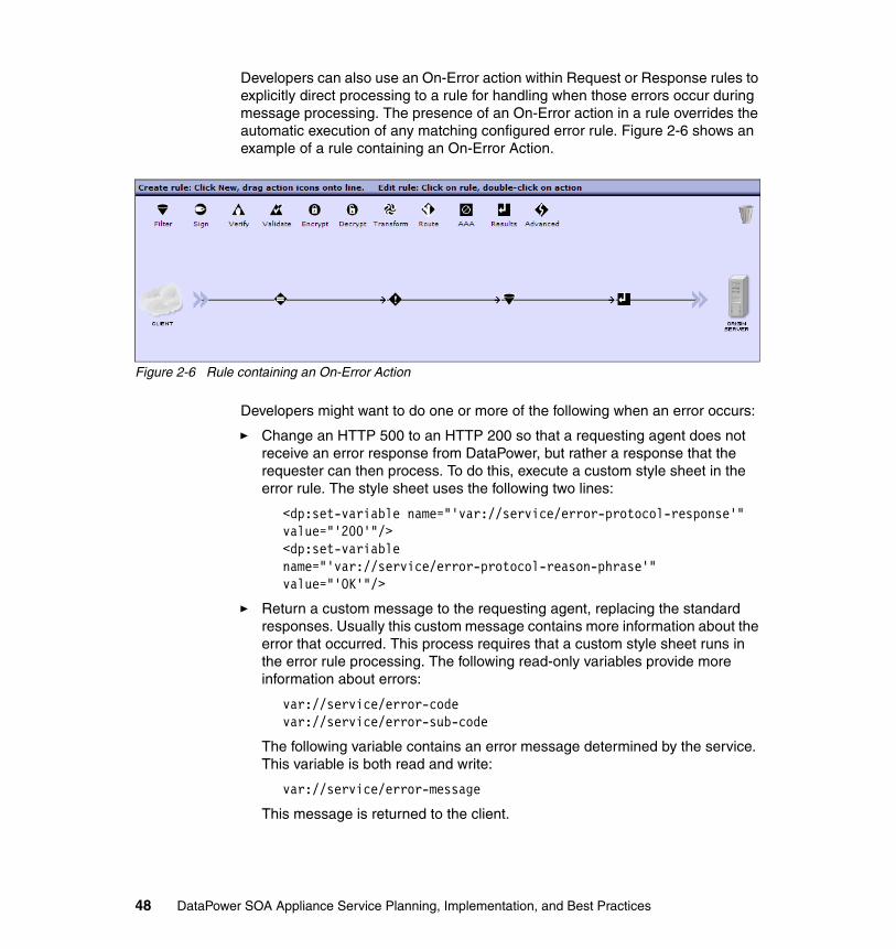
Developers can also use an On-Error action within Request or Response rules to explicitly direct processing to a rule for handling when those errors occur during message processing. The presence of an On-Error action in a rule overrides the automatic execution of any matching configured error rule. Figure 2-6 shows an example of a rule containing an On-Error Action.
Figure 2-6 Rule containing an On-Error Action
Developers might want to do one or more of the following when an error occurs:
� Change an HTTP 500 to an HTTP 200 so that a requesting agent does not receive an error response from DataPower, but rather a response that the requester can then process. To do this, execute a custom style sheet in the error rule. The style sheet uses the following two lines:
<dp:set-variable name="'var://service/error-protocol-response'" value="'200'"/><dp:set-variable name="'var://service/error-protocol-reason-phrase'" value="'OK'"/>
� Return a custom message to the requesting agent, replacing the standard responses. Usually this custom message contains more information about the error that occurred. This process requires that a custom style sheet runs in the error rule processing. The following read-only variables provide more information about errors:
var://service/error-codevar://service/error-sub-code
The following variable contains an error message determined by the service. This variable is both read and write:
var://service/error-message
This message is returned to the client.
48 DataPower SOA Appliance Service Planning, Implementation, and Best Practices

� Redirect a request message that encounters an error to an alternate processing path rather than immediately returning an error. This is done using the On-Error action with the Error Mode set to Alternative.
Error rules can also generate log messages or take other actions as needed. The type and degree of error handling needed for a particular implementation depends on the policy of the enterprise.
2.6 General considerations
This section presents usage considerations and best practices on a range of features and objects on the device.
2.6.1 Service chaining
In some cases, the message processing that is offered by a single service, such as a Web Service Proxy, cannot meet the required need (for example, providing a single point of entry into hundreds of internal services). In such cases, using two services, such as a Multi-Protocol Gateway and one or more Web Service Proxies, does meet the required need. This is called service chaining.
Whenever service chaining is used, consider the following issues regarding security and performance:
� All XML content must be serialized before transmitting between services, which takes time and resources.
� The entry point to the second (and later) services in the chain present potential security holes if not configured correctly. These services must only use the 127.0.0.1 Internet address for front side access; otherwise, remote clients can discover a means to circumvent the first service in the chain.
� Do not use persistent TCP connections between services; this impedes performance.
� Any packaging and deployment of a solution configuration that involves more than one chained service must include all services. Exporting any single service in the chain does not automatically bring the related services into the export package. Locate all services of a chain in a single domain and export the domain configuration as a best practice for migrating such solutions.
� Be aware of the order in which chained services become active during a reload or reboot. The service that provides the initial contact point to clients can become fully available before the remainder of the services in the chain become fully available, resulting in a load balancer performing a health check
Chapter 2. Service implementation and optimization 49

that returns positive when, in fact, the entire processing chain is not yet ready. You might need to build in a delay or warm-up time to allow all services in the chain to become active.
� Errors from a destination back end service do not return directly to the requesting client, but rather return through the service chain. Any custom error handling that is needed across the chain must be designed into the message flow.
In general, service chaining is robust and fast and does run in production environments. Designing a solution that requires only one service provides better results.
2.6.2 SOMA Execute Scripts through XML Management Interface
While the XML Management Interface supports the execution of many commands, not all are supported. To execute commands that are not directly supported, create CLI scripts that contain the desired actions. These CLI scripts can then be executed through the XML Management interface.
2.6.3 XML Manager
Every service, such as a Web Service Proxy or Multi-Protocol Gateway, employs an XML Manager object. An XML Manager obtains and manages XML documents, style sheets, and other resources on behalf of one or more services. A single XML Manager supports any number of services. When an XML Manager is shared among many services, all services receive the same support from the XML Manager.
Employing unique XML Manager objectsEvery application domain automatically contains a default XML Manager. This default manager sets recommended levels for such things as XML threat protection and caching.
Furthermore, it is recommended that each service employ its own unique XML Manager to eliminate the possibility that changes made to the object to support one service inadvertently break the behavior of another service in the same domain.
Note: To preserve the default XML Manager settings, it is recommended that developers create a new XML Manager for use with any services in that domain.
50 DataPower SOA Appliance Service Planning, Implementation, and Best Practices

Configuring document cache The XML Manager automatically caches retrieved files, eliminating the need to obtain remote resources on each invocation. This cache can hold both XML and non-XML files. Caching non-XML files becomes important when using remotely stored map files (mapfile.dpa) for binary transformations.
This can be achieved by configuring the XML Manager Document Cache Policy Type as Fixed with a URL Match Expression designed to match map files (that is *.dpa). The TTL value then determines how often the XML Manager retrieves a fresh copy of the map files, as shown in Figure 2-7.
Figure 2-7 Configuring a Document Cache Policy
2.7 Streaming
This section discusses the file streaming within the DataPower appliance along with its advantages and considerations.
Chapter 2. Service implementation and optimization 51

2.7.1 Advantages of streaming
Streaming a file through the appliance means that the appliance begins to send data to the back end destination before reading all data from the front side connection. An in-memory copy of the entire request message never exists on the appliance. As a result, a service can handle much larger request file sizes (as much as 1 GB or more). This ability allows the service to proxy an enterprise service that accepts large submissions.
Streaming is the only way to safely transfer large files. Using normal operation modes exceeds the available memory on the device and causes a throttle or other failure.
A number of constraints must be met to successfully use a service in streaming mode.
2.7.2 Constraints of streaming
The device streams messages when configured correctly. Streaming places a number of constraints on the configurations available to support streaming, which we discuss in this section.
DataPower style sheet not compatibleNot all stylesheets are compiled as streamable in DataPower. When compiling a style sheet, the appliance determines whether it can be streamed or not. If the style sheet cannot be streamed, it is processed using the DOM model, and a warning message is logged.
Using any of the following functions or commands can compromise streaming:
� The appliances will not stream when the following or preceding axes in an XPath expression are used.
� Any command to force processing nodes out of order, such as the SORT operation.
� Using global parameters or variables that select the input document.
� Using the XslNumber command.
� Using the evaluate, Id, or Key functions.
� Using the Last, Current, or Count functions on portions of the input document.
DataPower style sheet partially compatibleA style sheet can also be compiled as partially streamable. In this case, streamable parts are processed using the streaming mode, and non-streamable
52 DataPower SOA Appliance Service Planning, Implementation, and Best Practices

uses the DOM model (the DataPower reads the complete node and processes it using DOM when needed). Although partial streaming is slower than full streaming, it also keeps memory usage down.
Using any of the following functions and commands can compromise streaming:
� xsl:if statements
� xsl:choose and xsl:when statements, which is true for any condition except xsl:foreach statements
� Boolean tests between node sets where one is the input document
� Any style sheet that checks a node for two different purposes
Troubleshooting a style sheet compatibility with streamingDataPower provides a functionality when needed to validate whether a style sheet is compatible with streaming mode or not:
1. Create a new policy (or use the one you already have) with a transform action referencing your style sheet.
2. Enforce streaming by setting it on the Compile Options Policy in the XML Manager for the service.
3. Send any data to the service, which triggers the compilation of the style sheet. An error message will be sent back when the style sheet is not compatible.
4. On the left menu, access Status XML Processing Stylesheet Status.
5. Find the compiler details under the Compiler Log column.
2.7.3 DataPower processing actions compatibilities
Not all of the processing actions support streaming. If a service is not well set (meaning it is not set using only streamable action), it will not stream at all and processing large files can cause an overload on memory usage that was not expected.
The only processing actions that support streaming are:
� Transform (xform)� Validate (validate)� Binary Transform (xformbin), if licensed for DataGlue
If a processing policy uses more than one action (for example, both a transform action and a validate action, or perhaps more than one transform action), the contexts that is used to connect the actions must be set to PIPE. Thus, the processing policy might contain the following actions in a processing rule:
Chapter 2. Service implementation and optimization 53

� A validate action with the INPUT input context (original message from front end client) and the PIPE output context
� A transform action with the PIPE (the output context from the previous action) and the OUTPUT output context (results to backend server)
Processing rulesWhen you must transfer files with several types and sizes, a good recommendation is to use more than one processing rule. A good example is to have a specific rule for large files streaming only, and to have more rules to deal with the other files. This way it becomes easier to build streamable services and rules on DataPower.
2.7.4 Streaming attachments
The XML Firewall, Multi-Protocol Gateway, and Web Service Proxy can handle processing of XML attachments. Their configuration provides the following features for XML attachments processing:
� Strip: Removes all attachments
� Reject: Rejects a message with at least one attachment
� Accept: Processes attachments based on three predefined modes: Allow, Streaming, and Unprocessed. Allow mode causes the device to build a manifest of all attachments, which defeats streaming. Do not use Allow mode for streaming attachments.
We discuss the Streaming and Unprocessed modes in the next sections.
Streaming modeThe Streaming mode provides limited processing when compared to the Allow mode. Because performance is better in this mode, it is the best option when processing large attachments.
Consider the following behaviors of streaming attachments:
� Processing can be applied individually to each attachment.
� The appliance does not create a manifest of all attachments.
� Attachments must be accessed and processed in the order that they appear in the package.
Note: Style sheets also must be compatible with the DataPower processing criteria. Otherwise your service might end up not being streamable even when using the right processing actions.
54 DataPower SOA Appliance Service Planning, Implementation, and Best Practices

� If streaming fails, for instance due to an incompatible processing action or style sheet, the attachment is buffered.
Unprocessed modeThe Unprocessed mode supports messages with attachments, but it does not provide any processing of attachments. So it is the best option when large attachments are required but no processing is required. In most cases, the root part of the message has a SOAP content, and DataPower can apply filter and transform on it if needed. It is the best option when processing SOAP with large attachments.
Comparison of the modes� Use the Unprocessed mode when an attachment does not need to be
processed.
� Use the Streaming mode if large attachments with limited processing are required and the attachment can be processed as a stream of bytes.
Attachment configuration considerationsAfter enabling attachment streaming, there are additional configuration steps. Some steps are specific for non-XML attachments:
� Enable chunked uploads for Multi-Protocol Gateway services and Web Service Proxy services. The service option Allow Chunked Uploads must be set to on or the message will be buffered in the appliance.
� Set Stream Output to Back and Stream Output to Front to Stream messages for directional streaming of attachments. This option is set under the object view of the service.
� For each expected non-XML attachment Content-Type, create a Matching Rule for the processing rule in the processing policy. With streaming attachments enabled, passing a non-XML attachment will log parse errors unless a separate processing rule is created to handle the non-XML attachment.
Use an HTTP matching rule with the HTTP Header tag value of Content-Type and the value of the Content-Type header set in the HTTP Value Match. For example, to pass a message with an attachment Content-Type of application/octet-stream, the processing policy must have a matching rule with the Matching Type of HTTP, the HTTP Header tag value of Content-Type, and with the HTTP Value Match that matches application/octet-stream, such as *octet-stream*.
Note: If the attachment is referenced in any of the style sheets or actions, the attachment is buffered.
Chapter 2. Service implementation and optimization 55

� For non-XML attachments, enable Unprocessed mode for each processing rule. Processing rules for non-XML attachments need Unprocessed mode enabled to permit the rule to pass the non-XML data unprocessed. Unprocessed is off by default. Do not confuse this property with setting the Request attachment processing mode and Response attachment processing mode to Unprocessed.
56 DataPower SOA Appliance Service Planning, Implementation, and Best Practices

Chapter 3. Managing keys and certificates
Keys and certificates are the basic components that are used for encryption, decryption, signing, and providing credentials. This chapter discusses the usage and some best practices for managing the appliance's keys and certificates.
3
© Copyright IBM Corp. 2011. All rights reserved. 57

3.1 Overview of keys and certificates
Keys and certificates are used for cryptographic functions. Understanding how to manage the keys and certificates on the DataPower appliance is important because this can affect the overall security of the network and the integrity of messages.
Secure Sockets Layer (SSL) is a common implementation for securing data transfer over a network. Typically, SSL connections are required to be terminated when reaching the DataPower appliance. This means that the appliance must store its own keys and certificates to allow this.
Public key cryptography uses a certificate (which contains a public key) and a private key. Public keys and private keys can be imported on to the appliance or generated directly on the appliance.
The public key is typically stored in a certificate, which can be a self-signed certificate that is generated on the appliance or an imported certificate that is signed by a trusted Certificate Authority (CA).
Session keys are secured with public key cryptography and then used to securely transfer data using SSL.
The three common SSL scenarios using the DataPower appliance depend on which side of the connection the appliance is responsible for securing:
� DataPower appliance acts as an SSL client as a forward proxy: If the appliance is set to authenticate and validate certificates, the appliance must have a certificate that contains the public key to trust the back end server.
� DataPower appliance acts as a SSL server as a reverse proxy: The appliance must have a private key when acting as an SSL server.
� DataPower appliance acts as a “two-way” proxy: The appliance must be configured to both initiate connections as an SSL client and terminate connections as an SSL Server.
3.2 Usage
Taking the components of cryptography and putting them together within the DataPower appliance configuration requires an understanding of the various relationships that these pieces have with each other.
58 DataPower SOA Appliance Service Planning, Implementation, and Best Practices

3.2.1 Basic cryptographic components
On a DataPower appliance, the basic components for cryptographic functionality are the private keys and certificates. The certificates typically contain a corresponding public key, digital signature, and further information about who signed the corresponding public key. Figure 3-1 shows an Identification Credentials object.
Figure 3-1 Relationship of Crypto Key, Cert, and Identification Credentials
The appliance allows these cryptographic artifacts to be associated with specific cryptographic configuration objects for use within a service.
A Crypto Key configuration object maps to a private key, and a Crypto Certificate configuration object maps to the certificate. Pairing a corresponding Crypto Key object and Crypto Certificate object creates a Crypto Identification Credentials object.
Additional certificates can be added to the Crypto Identification Credentials object to provide the chain of certification authorities to be sent along with the certificate during SSL negotiation.
Chapter 3. Managing keys and certificates 59

Figure 3-2 shows how to add a certificate.
Figure 3-2 Validation Credentials
A collection of certificates can be grouped into a Crypto Validation Credentials object. A Crypto Validation Credentials object typically can contain:
� An explicit set of certificates that are considered permissible.
� A set of Certification Authority (CA) certificates that allow any certificate issued by a CA to be considered permissible.
The DataPower appliance allows an Identification Credentials object to be associated with a Validation Credentials object within a Crypto Profile for SSL usage. If the appliance acts as an SSL server, the Crypto Profile must contain an Identification Credential.
If the Crypto Profile also contains an optional Validation Credential object, the appliance can request the peer (the SSL client) to authenticate itself as part of the SSL handshake for mutual authentication.
60 DataPower SOA Appliance Service Planning, Implementation, and Best Practices

If the appliance acts as an SSL client, it will use the Validation Credential object in the Crypto Profile to determine whether the SSL server's certificate is permissible. As an SSL client, the appliance uses the optional Identification Credential object if the SSL server requests client authentication for mutual authentication.
If no Validation Credential is present, validate using the certificates in the pubcert: directory. The SSL direction is set to Forward, and a “forward” Crypto Profile is defined.
Because SSL is terminated with the DataPower appliance, the appliance can act as both a server to receive an incoming SSL connection and as a client to initiate an outbound SSL connection. In this case, two sets of identification and validation credentials are required, one for each connection. The SSL direction is set to “two-way” and both a “reverse” and a “forward” Crypto Profile are defined.
There is an SSL proxy profile object that refers to Crypto Profile objects. An SSL proxy profile might refer to a forward (DataPower as an SSL client) Crypto Profile or to a reverse Crypto Profile (DataPower as an SSL server).
3.2.2 Hardware Security Module
When discussing the management of keys and certificates it is important to make the distinction between DataPower appliances that use the Hardware Security Module (HSM) and those not equipped with an HSM.
The DataPower appliance accelerates certain cryptographic operations and offers an additional optional supplement for purchase called an HSM.
The HSM allows for similar acceleration capability as the non-HSM appliances, but additionally provides a separate secure private key storage location than the flash file system.
If using an HSM appliance, the keys must be stored on the HSM. If using a non-HSM appliance, the keys are stored in the flash file system.
Unless you use an appliance with HSM hardware, keys cannot be imported or exported.
Note: The HSM has received FIPS 140-2 certification - level 2 or level 3 depending on how it is configured.
Chapter 3. Managing keys and certificates 61

3.2.3 Cryptographic tools
The DataPower appliance includes a collection of useful cryptographic tools, which you can access by selecting Administration Crypto Tools. This section describes these tools.
Generate KeyThe Generate Key action generates a private cryptographic key on the appliance and optionally a corresponding self-signed certificate. By default, the Generate Key action also creates a corresponding Certificate Signing Request (CSR) that is needed by a Certificate Authority (CA). CA policies can vary with the amount of information they require in a CSR; therefore, we recommend checking with the CA before generating a CSR to ensure that sufficient information is provided. Figure 3-3 on page 63 shows the appliance key generating panel.
62 DataPower SOA Appliance Service Planning, Implementation, and Best Practices

Figure 3-3 Generate Key panel
Export Crypto ObjectThe Export Crypto Object action creates an export package for a certificate or key object. When the action completes, the export package is in the temporary: directory on the appliance and can then be copied from the appliance.
This tool allows certificate objects to be exported on any appliance.
Key Objects can only be exported on an HSM-equipped appliance. On non-HSM appliances, the interface does not display properties that are associated with keys and the pull-down only displays the Certificate option.
Figure 3-4 on page 64 shows the Export Crypto Object panel.
Chapter 3. Managing keys and certificates 63

Figure 3-4 Export Crypto Object panel
Import Crypto ObjectThe Import Crypto Object action imports an export package that contains a certificate or key object. To use this action, the export package must be on the appliance.
This tool allows certificate objects to be exported on any appliance.
Key objects can only be exported on an HSM-equipped appliance. On non-HSM appliances, the interface does not display properties that are associated with keys, and the pull-down only displays the Certificate option.
Add SSH Known HostUse the Add SSH Known Host tool to create a list of SSH-known hosts. While this is not typically required, this tool provides the ability to explicitly define hosts as a known hosts. This feature is useful to update after a firmware upgrade or whenever an SSH server key is changed.
Convert Crypto Key objectThe Convert Crypto Key object writes a Crypto Key object to a file in a specific format.
Convert Crypto Certificate objectThe Convert Crypto Certificate object writes a Crypto Certificate object to a file in a specific format.
Note: The file designated must reside in the same directory as the private key object file if private fields are used in the output format. The output format includes private fields of the key. The file must be in the same directory as the configured file of the private key object. The OpenSSH pubkey format does not contain any private fields.
64 DataPower SOA Appliance Service Planning, Implementation, and Best Practices

3.2.4 Certificate storage
Certificates are stored on the appliance in specific, secure locations in the file system. There are three particular directories for storing certificates on the appliance:
� The cert directory stores uploaded certificates for a specific application or domain. This folder cannot share certificates across domains.
� The pubcert directory stores commonly used root certificate authorities.
� The shared directory stores commonly shared certificates that can be used across domains.
Either upload certificates directly to the file system or use the Import Crypto Objects tab of the Crypto Tools panel to import certificate objects.
Using the Import Crypto Object tool to import certificates automatically creates a corresponding Crypto Certificate object.
If directly uploading the certificate files, the Crypto Certificate objects must be created manually.
3.2.5 Key storage on a non-HSM appliance
When using a non-HSM equipped appliance, keys cannot be directly imported using the Crypto Tools. The key must be directly uploaded to the file system into the secure cert directory.
After the key is uploaded, the key cannot be retrieved, copied off, or included in an appliance configuration backup.
The only time a key can be exported off of a non-HSM equipped appliance is:
� If the key is generated on the appliance with the option for export explicitly enabled, a copy can be found in the temporary directory.
� If the appliance is set for a secure backup using a Disaster Recovery setting enabled during the appliance initialization.
3.2.6 HSM key storage
The intended purpose and benefit of the HSM is having a secure place for private key storage (that has received FIPS 140-2 certification). To use this functionality,
Note: Certificates cannot be stored or imported into an HSM, only keys.
Chapter 3. Managing keys and certificates 65

the Crypto Key (RSA private key) objects must point to locations inside of the HSM (locations beginning with hsm://hsm1/).
The non-HSM equipped appliance can only use Crypto Key objects pointing at the appliance flash file directory (for example, cert:///privatekey.pem).
Use the Import Crypto Object tool to import the key onto the HSM. The full security benefit of the HSM is utilized when using the keygen to create a private key that has never left the inside of the HSM or when the imported key file was exported from another HSM.
The file can be in any of the supported private key formats: DER, PEM, PKCS#8, or PKCS#12. It can also be the output of the Crypto Tool key export from an HSM-equipped appliance.
The HSM only stores RSA private keys. It does not store DSA keys (public or private), RSA public keys, X.509 certificates, or symmetric keys (AES or 3DES).
HSM initializationThe HSM arrives in an uninitialized state. The HSM can then be initialized in FIPS 140-2 level 2 mode or in FIPS 140-2 level 3 mode. An uninitialized HSM cannot store keys and is limited in most RSA operations (basically only SSH and SSL will be able to do RSA).
To initialize the HSM, the hsm-reinit command is executed from the CLI (to put it into either level 2 mode or level 3 mode), and then the appliance must be rebooted to complete reinitialization.
HSM status providersThe two HSM related status providers are:
� WEBGUI: Status Crypto Accelerator Status (CLI: show crypto-engine)The crypto-engine status provider shows the type of crypto hardware an appliance has (an HSM appliance shows hsm1), which HSM mode initialized, and the current status.
� show hsm-keys: The hsm-keys status provider shows all of the keys stored inside of the HSM. For each Crypto Key residing in the HSM, two rows of information are shown in this status provider (one private and one public).
Note: Do not use HSM to store files other than keys. HSM is not a file system.
Note: Be careful when switching HSM modes because all keys inside are permanently destroyed during this operation.
66 DataPower SOA Appliance Service Planning, Implementation, and Best Practices

To delete keys from the HSM, the easiest way is to use this status provider in the WebGUI (it provides a delete button sitting right in the table). This status provider is per domain, which means that its output (and the meaning of hsm://hsm1/mykey) depends on which domain is logged into.
Differences between level 2 and level 3 modeThe main difference between level 2 mode and level 3 mode is the use of the Pin Entry Device (PED). In level 2 mode, no PED is required at all, and the device can power on like any other DataPower device (without needing human interaction). To use level 3 mode (or even to use hsm-reinit to get out of level 3 mode) use the PED. At boot time, insert the black PED key and type its PIN into the PED. Only then will the appliance boot with a functional HSM. If this process is skipped, the appliance eventually boots but the HSM will not be functional; instead, it will behave like an uninitialized HSM until the appliance reboots and somebody uses the PED properly.
PED keysThere are four PED keys: grey, blue, red, and black. The grey and blue key represent the security officer (SO) role in the FIPS documentation. The red key controls key sharing between two HSMs. The black key represents the USER role in the FIPS documentation.
If using the HSM in level 2 mode only, then PEDs are not required. If using it in HSM level 3 mode, at least one is required. One PED can be shared between any number of appliances (it is a matter of logistics to physically move it around between them, though). Two different kinds of PED cable might be needed if only one PED is available to administer a mix of RoHS and non-RoHS HSM appliances.
FIPS 140-2 Level 3 requires a secure channel for the login of the HSM user before secrets can be accessed. The PED is how this particular HSM chose to implement that secure channel. Each HSM does this differently.
HSM private key exportUnlike the non-HSM appliance, the HSM appliance supports the export of private keys using the crypto-export command. For key export to work, these conditions must be met:
� HSMs must be initialized and in the same key sharing domain on the exporting and importing machines.
� The private key in question must be marked exportable at keygen time (see keygen's exportable option).
� HSMs on exporting and importing machines must share internal key wrapping keys (see the hsm-clone-kwk command).
Chapter 3. Managing keys and certificates 67

Each HSM has a special key inside of it, the key wrapping key, which is used to encrypt exported private keys and to decrypt imported private keys. If the goal is to restore exported keys to the same appliance, most of what is described in this section is not required (hsm-clone-kwk, red keys, or the hsm-domain parameter). This is because the key wrapping key at import time will already match the key wrapping key at export time because the HSM device is the same. However, if the goal is to move exported keys from one appliance to another one, you must follow all of the steps in this section.
The requirements are:
� First, the two HSMs in question must both be initialized and in the same key sharing domain. This means that they must both be initialized in the same mode (both in level 2 or both in level 3). In level 2 mode, they must have used the same hsm-domain parameter during hsm-reinit (this parameter has a default value that is the same on all appliances). In level 3 mode, they must have used the same red PED key during hsm-reinit (and the second initialization must not have overwritten the key value from the first initialization).
� Second, the key to be exported must be exportable. The exportability of keys is immutable. It is determined at keygen time, and it is controlled by that command's exportable parameter. If a key was created outside of the appliance (not using keygen), it is always considered exportable.
� Finally, before the crypto-export crypto-import sequence, the key wrapping keys must be synchronized using the hsm-clone-kwk command. This command must be run four times: one time on the source HSM appliance (with the key wrapping key being copied), one time on the destination HSM appliance, once again on the source HSM appliance, and once again on the destination HSM appliance. Each time the command is run, it will need the output file from the previous step (as the input to the current step), which must be moved manually (usually with the copy command).
After all of this is complete, private keys can move from system-to-system with crypto-export and crypto-import.
Note that the non-HSM appliance can export keys immediately at keygen time, but never at a later time. To export keys at keygen time, use the export-key parameter (not to be confused with the exportable option that controls later exportability on HSM appliances).
3.2.7 Using Certificate Revocation List
Using a Certificate Revocation List (CRL) is useful to validate certificates between the time they are issued and when they expire.
68 DataPower SOA Appliance Service Planning, Implementation, and Best Practices

The DataPower appliance can be set to retrieve a CRL for use in validating certificates. A certificate revocation list update policy enables the periodic refresh of CRLs that the appliance stores for checking. To use CRLs, enable the CRL Retrieval object, and add at least one instance of the CRL Policy object.
If an unexpected failure occurs due to validation against a CRL, be sure to examine the log entry to see if the message indicates that the certification validation failed because of the certificate being revoked or if the CRL retrieval itself failed.
3.2.8 Using the Certificate Monitor
The DataPower appliance has a built in Certificate Monitor to periodically check whether the certificates are expired. The Certificate Monitor scans all certificates when first enabled and the polling frequency of the certificate expiration checking can be configured. The Certificate Monitor can be configured to generate log messages when certificates approach their expiration date.
Each certificate object can be configured to ignore expiration, but an expired certificate can still fail if validated during a transaction.
By default, the appliance does not disable certificates and credential sets that use the expired certificate when the certificate expires.
If the certificate is expired and not set to ignore expiration, the Certificate Monitor can be configured to mark the key object and any dependent objects down.
If Disable Expired Certificates is set to on, all objects that use the expired certificate (either directly or through inheritance) are disabled and are no longer in service, for example, certificate expiration triggers the disablement of the associated certificate. Disablement of the certificate triggers the disablement of all firewall credentials, identification credentials, and validation credentials that use the expired certificate. In turn, crypto profiles that use disabled identification credentials and validation credentials are disabled, which leads to the disablement of SSL proxy profiles that depend on the now-disabled crypto profiles. If this security measure is enforced, the DataPower service can be disabled as the result of a referenced certificate expiration.
An alternative to using the Certificate Monitor is to monitor for the log event shown here using SOMA, SNMP, a log target, or some other monitoring method:
0x01b6000c cryptoinfo Certificate is about to expire
Note: The appliance supports CRLs that are in the DER format only and must conform to RFC3280.
Chapter 3. Managing keys and certificates 69

3.3 Best practices
This section provides some recommendations to consider when managing the DataPower appliance key and certificates.
3.3.1 Managing certificates
Be sure to store the certificates in the appropriate directory as a best practice for proper organizational reference.
If a certificate is exported using the Export Crypto Object tool, the certificate is encapsulated within DataPower configuration object xml and might need to be edited to revert back to a standard PEM file format.
3.3.2 Managing keys
For non-HSM equipped appliances, imported keys cannot be retrieved except within a secure backup. A secure backup can include keys except for keys on an HSM. For HSM appliances, keys can be imported and exported from the HSM.
3.3.3 Using HSM for managing keys
Any HSM-enabled appliance must have the HSM initialized manually to avoid issues with some secure transactions and to make sure all keys are stored in the HSM (only stores keys, not certificates).
If HSM private key operations are running slowly, check to see if any Crypto Key objects reside in the flash file directory (cert:///alice.pem). If Crypto Keys are found in a flash directory, use the crypto-import action to move the Crypto Key object inside of the HSM (hsm://hsm1/alice).
Using a Crypto Key in the flash directory functions much slower because it must be imported into the HSM, used, and then deleted on every single RSA operation. Certificates and public keys do not have this problem.
Note: Certificates, keys, or any other such sensitive material must not be stored on the local: directory.
70 DataPower SOA Appliance Service Planning, Implementation, and Best Practices

3.3.4 Import keys and change configuration to use them from HSM
In the domain where the key is stored, create an imported object for each private key by selecting Administration Crypto Tools Import Crypto Object.
When importing a private key, choose a new Object Name for the imported copy of that key. After importing the keys, update the configuration so that the keys use the imported object name rather than the name of the key stored on the file system. For example, looking into a processing policy where a key is used in a sign action and down at the bottom where the key is specified in a pull-down menu, change the key reference to the imported key object name.
After generated on the HSM, private keys have a unique link designed not to be used in different domains and cannot be imported from one domain to another.
3.3.5 Removing crypto objects
The crypto objects are built on top of each other. Understanding the order of these layers can help clarify the order in which to delete the objects properly.
The proper order of crypto object deletion is:
1. Clear out the third layer. Because SSL proxy profiles refer to crypto profiles, delete SSL proxy profiles first, and then delete crypto profiles.
2. Clear out the second layer. Crypto Identification Credential objects and crypto Validation Credential objects are independent of each other, so they might be deleted in either order.
3. Clear out the first layer. Crypto keys and crypto certificates can be deleted in any order.
3.4 Examples and real-life scenarios
In this sections, we provide some scenarios that can occur in user environments.
3.4.1 Exporting or listing keys
If the appliance is configured with an HSM, then keys can be exported, provided they were flagged as exportable when created. If the appliance does not have an HSM or some of the keys are not marked as exportable, the key(s) must be recreated in the new appliance.
Chapter 3. Managing keys and certificates 71

Keys that were originally generated on the appliance can be replaced by freshly-generated keys on the new appliance and corresponding certificates must be replaced with new ones.
Keys that were imported from an external source must be re-imported in the new appliance.
Keys contained within the appliance are listed on the Objects Crypto Configuration Crypto Key page.
3.4.2 Rebuilding certificate objects
To rebuild certificate objects:
1. Certificates can be installed in the new appliance on the Objects Crypto Configuration Crypto Certificate page.
2. Click Add to display the Configure Crypto Certificate window. Use the same name for the certificate object as on the original appliance.
3. Click Upload to upload the corresponding certificate file.
3.4.3 Rebuilding key objects
Each key identified by the previously mentioned process must be either re-imported or re-generated within the new appliance. For keys being re-generated, the process is application-specific, and will not be described here:
� Keys that were exported from the original appliance can be re-imported on the new appliance using the Administration Miscellaneous Crypto Tools Import Crypto Object tab.
� Keys that are in external (non-DataPower) files are imported using the Objects Crypto Configuration Crypto Key page. Click Add for each key to be imported from an external file.
Completely test the appliance before introducing the appliance back in to the production, development, test, or other environment.
72 DataPower SOA Appliance Service Planning, Implementation, and Best Practices

Chapter 4. Serviceability and Troubleshooting
This chapter provides guidance about Serviceability and troubleshooting for DataPower appliances.
4
© Copyright IBM Corp. 2011. All rights reserved. 73

4.1 Overview
The DataPower appliance includes a set of serviceability and troubleshooting capabilities that helps to enable identification, analysis, debugging, and resolution of a problem. Properly leveraging these resources can help restore a system back to its optimal state with minimal time and effort.
4.2 Benefits
The DataPower appliance has many offerings as a serviceability and troubleshooting solution. When something behaves unexpectedly in a complex system, understanding the troubleshooting tools that are available can greatly reduce the time to resolve any problems. The major components of the DataPower appliance troubleshooting and serviceability consist of:
� Testing network connectivity� Appliance statistics and status providers � System and Audit logs� Error reports and failure notifications � XML file captures and Multistep Probe
4.3 Usage
There are several troubleshooting tools and techniques that are available for the DataPower appliance. Understanding the capabilities for each available tool helps you make a more informed decision when selecting which set of tools to troubleshoot a particular problem.
In general, you must use certain tools during different parts of the development life cycle, while the error report can be used at any phase of the development life cycle. However, the most granular tools, such as debug loglevel and the multistep probe, must be used mainly during the development and test phase because these can be intrusive and generate a large amount of data in a high load environment.
After production, use the status providers, logs, and error-report to check on the operational state.
74 DataPower SOA Appliance Service Planning, Implementation, and Best Practices

4.3.1 Monitoring and Troubleshooting
When a problem occurs while using the DataPower product, the first place to start troubleshooting is the Troubleshooting section of the Control Panel.
Figure 4-1 shows the Monitoring and Troubleshooting Panel in the Control Panel.
Figure 4-1 Monitoring and Troubleshooting panel
In the Monitoring and Troubleshooting Panel, there are various tools and settings available to aid in identifying and resolving a problem, which we describe in the following sections.
4.3.2 Viewing logs
The logging level can help further isolate issues, check for errors, transaction flows, and messages to understand the underlying behavior of a problem.
Setting the loglevel to Debug and recreating the issue can capture valuable details about processing behavior, transaction flows, and help correlate with any errors that are seen. You can then view the logs by selecting View Logs in the Control Panel or directly from the file system, for example: temporary:///default-log
The log file is displayed in the WEBGUI as a table where each row of the table represents a particular event on the appliance. Figure 4-2 on page 76 shows an example of the log view in the WEBGUI.
Chapter 4. Serviceability and Troubleshooting 75

Figure 4-2 The System Log as seen in the WEBGUI
Example 4-1 shows the log view as a text file.
Example 4-1 Default-log viewed as a text file
20110307T021822Z [mgmt][notice] source-http(testHTTPFSH): tid(95): Service installed on port20110307T021822Z [mgmt][notice] source-http(testHTTPFSH): tid(95): Operational state up20110309T201216Z [network][error] : This is a sample log message sent from the Troubleshooting Panel20110309T201737Z [network][error] : This is a sample log message sent from the Troubleshooting Panel20110309T201754Z [network][error] : This is a sample log message20110309T201802Z [network][error] : This is a sample log message
Table 4-1 provides descriptions for the system log fields.
Table 4-1 System log fields
Field Description
Time The time at which this event occurred. By default, the logged events are sorted by time in the WEBGUI, most recent first. When viewing actual log files directly, the most recent events are appended to the end of the file.
Category Events are categorized with predefined categories that are listed at:
Objects Logging Configuration Log Category
76 DataPower SOA Appliance Service Planning, Implementation, and Best Practices

Level The message level provides an indication of the importance of the event and can be used to filter which events are recorded.
Domain Logs available in the default domain can show the domain associated with the event. Messages associated with the default domain do not contain this value.
Transaction ID A transaction ID might be displayed if the event is associated with a particular transaction and multiple events can be associated with a single transaction ID.
Direction Direction of the message in a request-response message sequence. The table cannot be sorted by direction. Possible values for this field are:� Request: A request transaction.� Response: A response transaction.� Error: An error occurred during transaction
processing.� Health: A status check within load-balancing groups.� Scheduled: A scheduled processing rule for an XML
manager.� Call: A scheduled processing rule for an XML
manager that uses the call action.� No value: A message that is not part of a
request-response message sequence.
Client The client IP address that submitted the request.
Message ID A message ID that identifies the event. Multiple events can share the same message ID.
Field Description
Chapter 4. Serviceability and Troubleshooting 77

4.3.3 Latency log messages
Latency messages are often contained within the default log. Here are two examples of WebSphere DataPower latency messages:
Mon Jan19 2011 13:23:40 [latency][info] xmlfirewall (loopback-fw): tid(2809): Latency: 0 1 0 1 1 0 0 1 1 1 1 1 0 0 1 1 [http://<IP address>:9999/test.xml]
Mon Jan 16 2011 13:04:27 [latency][info] xmlfirewall(TestLogging): tid(2075615): Latency: 0 0 0 0 1 0 0 1 0 0 0 1 0 0 0 0 [http://127.0.0.1:9999/]
The latency numbers measure in milliseconds the time elapsed since the beginning of a transaction. Usually, this is at the start of the HTTP transaction.
Table 4-2 describes the latency log format (numbers are in milliseconds).
Table 4-2 Latency log format
Message A short description of the event. This entry is a link that can be followed to obtain more information about the event, including suggestions for dealing with any problems. The table cannot be sorted by the message.
In the WEBGUI, log messages can be sorted by clicking on the relevant column header. Messages from the same transaction or service will have the same Transaction ID value.
It can be very helpful to:
1. Examine the log to identify the tid value for the service.
2. Filter the log by this tid value. The resulting subset of the log messages contains only those messages relevant to the service in question.
3. Sort the messages by level. The more important messages are listed at the top.
4. When you identify the relevant log message, click the message for more information.
Field Description
Position Argument
1 Frontside request headers read
78 DataPower SOA Appliance Service Planning, Implementation, and Best Practices

4.3.4 Error reports
A verbose debug report can be generated by clicking Generate an error report located at the bottom of the Control Panel.
Generating an error report will get an appliance-wide snapshot of the current system status providers, a cross-section of all available logs, and other debug information that can be used for troubleshooting.
The error report is typically requested by IBM Support to begin troubleshooting, but can be used by an administrator because it contains a large amount of diagnostic information in a single file.
2 Sent request headers out on backside connection
3 Ready to start buffering request body
4 All backside output created
5 All backside output sent
6 Request payload processor ready
7 Request payload processor input read
8 Read response headers
9 Sent response headers to frontside
10 Starting to buffer response data
11 All response data created
12 All response data sent
13 Response-side payload processor ready
14 Response-side payload processor input read
15 Backend connection started (this is when the connection is first tried)
16 Backend connection finished (or time connection attempt gave up)
Position Argument
Chapter 4. Serviceability and Troubleshooting 79

4.3.5 Packet Capture
The DataPower appliance can capture traffic tracing at the network packet level through the Packet Capture utility. Network traffic can be captured on a single interface, all interfaces, and even over the loopback.
Click Troubleshooting to open the Packet Capture utility, as shown in Figure 4-3.
Figure 4-3 Packet Capture utility
The amount of information captured can be limited by size, duration, or by a pcap-filter(7) format filter expression.
4.3.6 Probe function
When debugging a transaction that passes through many processing actions, the Probe function might need to be consulted.
The Probe can display useful transaction information like metadata, variables, headers, attachments, parameters, extensions, and execution tracing.
To enable the Probe function, there are basically two paths to follow:
� Activate the Probe function directly from the service:
Service configuration Show Probe Enable Probe
� Activate the Probe function from the Troubleshooting menu:
Control Panel Troubleshooting Debug Probe Select intended service Add Probe
80 DataPower SOA Appliance Service Planning, Implementation, and Best Practices

When using the first option, there are two additional configuration settings available:
� Probe Settings: Allows definition of the number of Transaction History. The default is 25.
� Probe Triggers: Allows capturing the transactions only when a specific criteria is met.
Consider using the two additional settings when the workload in the appliance is high and manual capture of the intended transaction might be difficult.
Understanding the Probe main windowThe Probe main window is divided into four sections, as shown in Figure 4-4:
� Navigation buttons: Navigates to the previous or next context or action.
� Selector area: Allows manual navigation through the context/actions.
� Display controls: Allows selection of what is to be shown.
� Display area: Shows details of context or action combined with the display controls.
Figure 4-4 Transaction captured by Probe function
Using the Probe function with the Validate actionIf the transaction contains a SOAP message type or if the rule being debugged is a request rule, the probe function will omit the first Validate action due to performance optimization. This happens because when the appliance processes
Probe function: Do not use the Probe function in production environments because it can degrade the performance of the appliance under a high load of transactions. Use this function strictly for debug purposes.
1
2
1
3
4
Chapter 4. Serviceability and Troubleshooting 81

a Validate action in the first step, it internally processes combining the action with an implicit SOAP schema validation, which happens even before the probe starts.
If debugging the Validate action is required, consider adding a new Transform action with no processing prior to the Validate action. Doing this removes the automatic performance optimization and forces the appliance to probe the Validate action.
4.3.7 XML File Capture
In cases when the Probe function cannot retrieve the content of the messages passing through the appliance, typically due to failure to parse, the XML File Capture tool can be an alternative.
Click the Troubleshooting icon Main Advanced XML File Capture or Main Menu Administration Debug XML File Capture to open the XML File Capture tool.
This function can only be activated from the default domain, and after it is active, it captures XML files for all domains running in the appliance. When the files reaching the services are captured, they can be viewed through Main Menu Administration Debug Browse Captured Files. A window similar to Figure 4-5 is displayed.
Figure 4-5 Browsing captured files
Due to its nature of capturing any XML file reaching any active service, handle this function carefully because this can certainly affect the performance of the appliance when enabled.
82 DataPower SOA Appliance Service Planning, Implementation, and Best Practices

The XML File Capture tool handles the maximum number of 5000 files or 200 MB of data. After this limit is reached, it start overwriting the files on a first in first out (FIFO) basis.
4.3.8 Status providers and statistics
The DataPower appliance configuration is built on interdependent configuration objects. There are many status providers that can query the current state or status of different objects and overall appliance health.
Status providers can be accessed through multiple interfaces in the appliance, such as:
� WEBGUI: The Status selection in the left navigation bar� CLI: show commands� SNMP monitoring� XML Interface
The current object status can be viewed using the View Status icon in the Control Panel
The DataPower appliance can also gather statistical data about various resources on the appliance. By default, the gathering of statistics is disabled for performance reasons and must be enabled for certain status providers. If a status provider requires that statistics to be enabled and it is not enabled, the window shows the “Statistics is currently disabled” message.
To enable Statistics, click Administration Device Statistic Settings in the left navigation bar.
Enabling statistics can allow the calculation of certain status providers like CPU Usage and Transaction Rates.
4.3.9 Failure Notification and First Failure Data Capture (FFDC)
System failures are, in most cases, unpredictable. Good monitoring can help detect when a system is about to fail, but in most cases it does not prevent a failure from happening. Having adequate and helpful information is essential when troubleshooting a system failure. Root cause analysis can be stressful and time consuming, but can become easier when enough information about the incident is available.
The Failure Notification function allows the capture of more diagnostic information, such as error report, memory trace, log capture, and packet capture.
Chapter 4. Serviceability and Troubleshooting 83

Building on failure notification, First Failure Data Capture (FFDC) can allow the appliance to capture information related to diagnostics during run time. This can be helpful when an unexpected failure occurs.
The Failure Notification function generates an error report and additionally can be configured to include the following diagnostics:
� Internal State� Packet Capture� Log Capture� Memory Trace
To open the FFDC, click Objects System Settings Failure Notification in the left navigation bar. Figure 4-6 on page 85 shows an example of the Failure Notification settings.
Enabling options: The Packet Capture, Log Capture, and Memory Trace features are not enabled by default. The administrator must consider serviceability and enable these options.
84 DataPower SOA Appliance Service Planning, Implementation, and Best Practices

Figure 4-6 An example of the Failure Notification setting
To use Failure Notification, you must enable the configuration and allow the error report to be uploaded. The impact on performance after enabling these features largely depends on the configuration. Test these features throughout the development life cycle to fully understand the impact.
When upload error report is enabled, the Failure Notification status provider is enabled. This status provider, in combination with the report history, tracks the error reports that the appliance generates, the reason why the appliance generated the error report, and its upload status to the specific destination.
The destination of the error report can be set to NFS, iSCSI, RAID, SMTP, FTP, or the temporary file directory. When the appliance generates error reports, the
Chapter 4. Serviceability and Troubleshooting 85

naming convention includes the serial number of the appliance and the timestamp of the report to prevent one error report from overwriting another.
The Include Internal State configuration parameter can be enabled to automatically include the internal state of the appliance in the error report, which can be useful in diagnosing the cause of the error.
The Background Packet Capture configuration parameter can be enabled to automatically include a network packet capture for all interfaces including the internal loopback interface at the time of the failure. When enabled, this feature runs continuously.
The Background Log Capture configuration parameter can be enabled to capture log and trace points with minimal overhead. When enabled, this feature runs continuously.
These messages are independent of messages written to log and trace targets and this features is not governed by any logging target configuration.
If the appliance encounters a problem or an error report is manually generated, the error report includes the Background Packet Capture and Background Log Capture data. This data can help determine the messages that the appliance was processing when it encountered the problem.
The Background Memory Trace configuration parameter can be enabled for automatic detection for gradual memory growth that might occur steadily over time. This feature is not designed to capture sudden resource issues related to parsing very large messages.
When enabled and if memory falls below an internal threshold, the appliance tracks all memory allocations. When the appliance reaches a critical condition, it generates an error report that contains information about memory allocation. The configuration of the Throttle Settings affects this feature and can prevent the appliance from reaching the internal threshold.
The Always On Startup configuration parameter can enable whether the appliance generates an error report when it reboots or reloads.
The Report History specifies the maximum number of local error reports to maintain when using the upload error report feature. After reaching this limit, the next local error report overwrites the oldest local error report. To view the history, use the Failure Notification status provider found in the Status section in the left navigation bar.
86 DataPower SOA Appliance Service Planning, Implementation, and Best Practices

4.4 Best practices
Due to the availability of such a diverse set of troubleshooting tools, monitoring, logging, and status providers, there can be multiple ways to proceed with problem determination. This section provides an overview of some best practices and general guidance for troubleshooting the appliance.
4.4.1 General troubleshooting
In general, if a problem occurs the first step is to try and isolate the root cause to help resolve the issue. Information about the issue is vital to understanding the true root cause.
The first step is to observe the issue’s behavior and try to isolate the issue to a specific application domain, service, interface, message, error message, and so on.
Here are the common methods for general troubleshooting of an issue:
� Check the appliance default log for any related messages.
� Check the audit log in the default domain for configuration changes that might be insightful.
� Check the object status to see what the operational state of this and any dependent object currently is.
� Check the overall appliance status to check the current load on the appliance and the length of the work queue.
� Check the CPU usage in the default domain.
� Check the running configuration for any changes or inconsistencies with the startup configuration.
� Check the status of the file system to see if space might be low.
� Check the style-sheet status to check the style sheet cache or to see if there are any errors or exceptions during style-sheet compilation or execution.
� Check the probe for a specific service to see how a message is processed and to view variable usage.
� Run a packet capture in the default domain to for review of network activity.
Chapter 4. Serviceability and Troubleshooting 87

4.4.2 FFDC
Keep in mind the following FFDC best practices:
� It is recommended to have Failure Notification enabled so that an error report is uploaded to a valid destination with all available information at the time of an issue. Because enabling Failure Notification with all of the FFDC features enabled can cause a moderate performance impact, consider the environment role. For example, a production environment might require more performance than a development or test environment; however, increased serviceability can expedite any problem resolution and might help prevent a production issue.
� It is recommended to use a reliable low latency protocol for remote upload for FFDC, such as NFS or FTP. Using a RAID array can also be an option if the device has that feature.
� Be careful with the DataPower temporary directory usage because the data stored in that temporary directory is not permanent and can use up finite local storage resources.
� Enable the Always On Startup option to allow the DataPower appliance to generate an error report when it reboots or reloads to be sure that data is captured during one of these events.
4.4.3 Import, export, and upgrading
If an issue occurs when trying to import a configuration file, export a configuration file, or upgrade the appliance firmware, take the following considerations to begin proper problem determination:
1. Be sure that the latest available firmware is being used.
2. Before exporting a configuration, importing a configuration, or upgrading the firmware, remove the appliance from the business solution, development environment, or test environment.
3. When upgrading the firmware on an appliance, make sure to wait until the firmware upgrade completes before entering other commands. If the appliance is equipped with the HSM feature, the reboot portions of the upgrade steps can take 15 minutes to complete.
4. If upgrade, import, or export is not working, check the throttle setting or temporarily disabled it in Objects System Settings Throttle Settings.
Note: In a production environment or any other environment with high load, enable this feature for tracking issues, reloads, and reboots.
88 DataPower SOA Appliance Service Planning, Implementation, and Best Practices

5. Execute Importing, Exporting, and Upgrading processes while changes are not in progress and while the appliance is not processing load.
After these are confirmed, check to see if there are any log messages indicating where the issue occurred.
One example, if a Firmware upgrade is unsuccessful and the following log message shows:
Upgrade failure in dynamic loader: Switch active firmware failed The dynamic loader failed to upgrade the system (-1). The resident loader will be used instead....
Confirm that the firmware upgrade was successful by checking the appliance firmware level using the WebGUI or the show version CLI command because this message is typically informational.
4.4.4 Debugging AAA
Understanding the precise location and cause of an Authentication, Authorization, Auditing (AAA) error begins with capturing useful data during the issue.
Common AAA issues are caused by misconfiguration, formatting issues, or connectivity problems.
A common formatting issue:
� The output from one step (often Authentication) is not consumable by another (often Authorization). Use Map Credentials and Map Resource to map the formats. This sometimes occurs when integrating X.509 certificate style Distinguished Names (DN) with LDAP Distinguished Names.
Useful data can typically be found by enabling debug loglevel and the multistep probe, and then recreating the issue.
The error report can show the correlating log messages and configuration settings referenced during the issue. Correlating the probe with the error report can help isolate configuration and connectivity issues.
After you recreate the issue, generate an error report for review.
Note: Take a secure backup after any firmware update because secure backup restore requires the device to be at the same firmware level as the backup.
Chapter 4. Serviceability and Troubleshooting 89

Often a simplified recreation can help expedite troubleshooting by only recreating the AAA steps that are relevant to the particular issue.
Some general AAA best practices to aid in serviceability and troubleshooting are:
� Ensure that the output from the Extract Identity step is unique for the current user when using Authorization caching or inaccurate results can occur.
� Avoid using the probe to determine the input to each step for custom steps.
� Avoid using custom templates where possible to take advantage of the proven functionality of existing templates.
� Do not use the var://context/WSM variables in or outside of an AAA action. Save them to a custom context variable instead or extract the values from the XSLT input.
� Do not configure more than one Post Processing method. Using multiple methods can result in unexpected behavior.
� The Extract Identity output might be more specific than expected or not cacheable, if so, then unexpected results can occur.
4.4.5 Debugging RBM
It is important to understand how Role-Based Management (RBM) functions and to understand the proper data to collect when troubleshooting an RBM issue.
The basic component of RBM is an access profile, which consists of one or more access policies and is an URL-style expression that grants or denies rights to a resource.
The policy has the form:
<device-ip>/<domain>/<resource>?Access=r+w+a+d+x&(key=value)
In the policy:
� <device-ip> is the device management ip address or * for any � <domain> is the resource domain or * for any � <resource> is unique resource type descriptor * for any
(key=value) can optionally be used to narrow down the resource instances using Perl Compatible Regular Expressions (PCRE), for example:
� Name� LocalPort� LocalAddress� Directory
90 DataPower SOA Appliance Service Planning, Implementation, and Best Practices

The access parameter defines the access the user has:
� (a)dd � (d)elete � (w)rite (modify existing resource instance) � (r)ead � e(x)ecute (for actions or login etc)
Explicitly denying access to the user is through the use of the keyword NONE, for example:
*/*/*/services/xmlfirewall?Access=NONE
This example denies any type of access to any firewall in any domain on any device.
Access is evaluated against policy with the longest best-match, so the order is not important, for example:
*/*/services/xmlfirewall?Access=NONE
*/*/services/xmlfirewall?Access=r+w&Name=^myName
This example denies access to all firewalls except for firewalls whose names start with “myName”.
Access can be set to “Allow All” by using the following example:
*/*/*?Access=r+w+a+d+x
Access can be set to “Deny All” by using the following example:
*/*/*?Access=NONE
Some general RBM best practices to aid in serviceability and troubleshooting are:
� Avoid using custom Authentication or Credential mapping. It is very difficult to debug custom XSLT in RBM without the probe.
� Be sure to utilize the RBM Info builder.
� Be sure to test all LDAP searches using an LDAP browser before attempting to debug in RBM.
� Be sure to check for some of the more common RBM issues, such as:
– Check to see if a fallback user is defined for any Remote Authentication scenario
Note: Be sure to frame your match expression with ^ and $ if your intend is an exact match.
Chapter 4. Serviceability and Troubleshooting 91

– Check to see if the Access Policy lists are incorrect
– Check to see if the XML File format is incorrect
– Check for any LDAP or Remote Authentication connectivity issues
– Check to see if LDAP Search is malformed or incorrect for users
– Check to see if LDAP Group Search returns multiple groups
To proceed with proper problem determination for RBM:
1. Enable the proper tracing from the Troubleshooting panel.
2. Consider increasing the size of the default domain log file because RBM debug tracing is very verbose.
The debug level tracing and logging settings can be enabled from the Troubleshooting icon.
3. On the Troubleshooting Panel, under Logging, set the Log Level to debug.
4. Set Enable RBM Debug to ON.
5. After RBM Debug is enabled, recreate the scenario, and inspect the logs.
6. Be sure to search for Authentication errors, which can be Authentication (AU) or Map Credential (MC).
For example, if the group access permission is '*/Domain/*?Access=r' and an action execution is attempted, the log will show an 'Access Denied' error message generated, as shown in Example 4-2.
Example 4-2 Access Denied log example
Thu Feb 17 2011 13:03:44 [rbm][debug] rbm(RBM-Settings): tid(27585)[request]:AZ: Parsing policy [*/Domain/*?Access=r]Thu Feb 17 2011 13:03:44 [rbm][debug] rbm(RBM-Settings): tid(27585)[request]:AZ REQ: Evaluating policy [all]Thu Feb 17 2011 13:03:44 [rbm][debug] rbm(RBM-Settings): tid(27585)[request]:AZ REQ: Policy denies permission [Execute]Thu Feb 17 2011 13:03:44 [rbm][debug] rbm(RBM-Settings): tid(27585)[request]:AZ: Reject Weight(10) - */Domain/*?Access=rThu Feb 17 2011 13:03:44 [rbm][debug] rbm(RBM-Settings): tid(27585)[request]:AZ: One policy rejects and none accepts - RejectThu Feb 17 2011 13:03:44 [auth][error] rbm(RBM-Settings): tid(27585)[request]:RBM: Access Denied
In this instance, changing the permission to '*/Domain/*?Access=rx' can resolve the execution 'Access Denied' error.
92 DataPower SOA Appliance Service Planning, Implementation, and Best Practices

4.4.6 Debugging network issues
Network issues can seem complex, but generally it is easier to break down the transaction flow into separate connections. For example, a networking issue might be easier to troubleshoot after the issue is isolated to the relative front-end, back-end, or a resource called over the network for a processing policy.
Use the following steps when debugging network issues:
1. The most basic test for network connectivity is to use the Ping Remote tool to check if the remote host can respond to an ICMP ping.
2. The next basic test for network connectivity is to use the TCP Connection Test tool to see if a remote host can respond at the host:port level.
Both of the Ping Remote and TCP Connection Test tools are available from the command line and Troubleshooting Panel in the WEBGUI.
3. Send a test message to validate whether the remote server accepts a request message and can respond:
Click Administration Debug Send a Test Message.
The most common problems can be attributed to an inefficient routing table, a timeout misconfiguration, negotiation issue, or some outside network problem. Be sure to make an informed decision on how to setup the routing table, decide on which side of each intended connection should timeout, and use multiple DNS servers and load balanced groups to reduce single points of failure.
It is recommended to set specific routes to control the route used by the appliance for outbound traffic.
It is recommended to use only one default gateway to help prevent traffic from being routed to an unreachable backend by accident.
If unexpected network performance occurs, check the following settings to make sure they are compatible with the network:
� DataPower TCP Segmentation offload setting� Explicit Congestion Notification (ECN) setting� Persistent connection settings� Chunked encoding
When experiencing network errors that affect performance, verify:
� Routing table efficiency� Interface configuration� Use of persistent connections� Timeout settings� Cache timeouts (if applicable)
Chapter 4. Serviceability and Troubleshooting 93

� Services layouts (chained or segregated)� Explicit Congestion Notification
To identify a network issue, the following tools are commonly used in conjunction with each other:
� Error report� Packet captures� On-board status outputs:
– Show route– Show int– Show int mode– Show network– Show tcp / show tcp summary
After this data is captured, review the data for any unexpected values, and try to identify any network-related errors in the error report.
Use specific pieces of information to further isolate the issue:
� Use the timestamp of the network issue to further isolate the activity in the error report.
� Use the IP Address and Port of the service to correlate with the data.
� Use the IP address of the client or backend server to correlate with the data.
� Use the Transaction ID for the failing transaction to follow other related log events.
� Using packet traces to troubleshoot network errors.
Packet captures can only be taken from the default domain.
Use a network protocol analyzer to view the file, such as the commonly used Wireshark utility.
Packet traces can be taken on all interfaces, including the loopback or specify a single interface.
If the problem can be isolated to a specific IP address (client or server) or type of traffic, then a filter can be used.
Example 4-3 shows an example of several CLI network status provider outputs.
Example 4-3 Network status output
show intinterface IP Address RX (kb/pkts/errs) TX (kb/pkts/errs)-----------------------------------------------------
94 DataPower SOA Appliance Service Planning, Implementation, and Best Practices

mgt0 9.33.83.119/23 0/0/0 0/0/0eth0 9.33.83.118/23 1435667/14103343/0 2172988/33865512/0eth1 0.0.0.0/0 0/0/0 0/0/0eth2 0.0.0.0/0 0/0/0 0/0/0 show int modeinterface status negotiate speed MAC address----------------------------------------eth0 ok auto 1000baseTx-FD 00:0a:4b:0b:a0:d0eth1 no-link auto 10baseT-HD 00:0a:4b:0b:a0:d1eth2 no-link auto 10baseT-HD 00:0a:4b:0b:a0:d2mgt0 no-link no 10baseT-HD 00:0a:4b:0b:a0:d4 show route (show in slide 9) show networknetwork [up]-------admin-state enabledicmp-disable Timestamp-Replyecn-disable offdestination-routing offrelax-interface-isolation ondisable-interface-isolation offtcp-retries 5arp-retries 8arp-interval 50tcp-segmentation-offload onreverse-path-filtering offNetwork status output show tcp
4.4.7 Debugging an unexpected restart
Ascertain the answers to all of the following questions to properly debug an unexpected restart:
� Where is this device located? Is it in a test or production environment?
� Are there other devices running the exact same configuration or behind the same load balancer as the device with the problem? If so, how many?
� Was there any type of load test, security port scan, or other atypical traffic hitting the device at the time?
� Have there been any configuration changes, client changes, or other changes to the environment prior to the event?
Chapter 4. Serviceability and Troubleshooting 95

� Was the appliance rebooted to recover? If so, were there any other steps taken?
� Any other recent changes related to DataPower appliances and environment?
Collect the following documentation from the time of the event. This is key to determining root cause.
Generate an error report. This can be done from the default domain Troubleshooting panel or from the command line using the co;save error command. This will generate the error report into the device's temporary: directory that can be downloaded and sent to IBM Support.
A full device backup is always helpful. If a service request (PMR) is already open with IBM DataPower support, and you submitted a device backup, indicate this to the L2 support person with whom you are working. Submit any and all statistical data about the device leading up to and during the event. The statistics can be from SNMP, XML Management retrieval, or other methods, such as command line (CLI), snapshots of the current state and any other information pertaining to the problem. Submit all off-device logging leading up to and during the time of the event, including syslog, NFS, SOAP, or other methods of off-device logging.
4.4.8 Memory growth/high CPU/high load
The First Failure Data Capture (FFDC) feature can impact performance or throughput, but it allows for a significant improvement in terms of isolating and determining root cause in the event of an unexpected reload or reboot.
Off-device logging is key to debugging problems. In most cases, a specific log target per domain with the event subscription of all and error is needed.
Device monitoring through the command line interface (CLI) is available for gathering statistics. This can help in a number of issues and cases from unexpected reloads, reboots, to slow response, throttling, and so on. The interval at which you perform the CLI captures is dependent on the speed at which the problem occurs. For normal operating conditions, this can be as infrequent as once every 12 hours.
If the appliance has a throttle in place, the high memory usage (load) might be causing the throttle to refuse connections. To view, click Administration Device Throttle Settings in the left navigation pane. Finding the cause of excessive memory can involve the use of other tools.
96 DataPower SOA Appliance Service Planning, Implementation, and Best Practices

4.5 Examples
This section provides some examples to aid in troubleshooting.
4.5.1 Monitoring resource growth over time
When troubleshooting resource growth issues, taking Command Line Interface (CLI) snapshots over intervals can be useful for isolating the issue.
You can manually run the following commands over time:
� diag� set-tracing on� exit
After you set the tracing to on, capture the output of the following commands over several iterations while the issue is occurring for comparison:
� show clock� show load� show cpu� show throughput� show tcp� show int� diag� show mem� show mem details� show handles� show activity 50� show connections� exit
These commands can be automated in a script. Example 4-4 shows a sample shell script that you can run.
Example 4-4 Sample shell script for automation consideration
#!/bin/ksh# IBM DataPower L2 Support, [email protected]## The script is provided as it is.## The script will run 7 times, once every 5 mins and collect sample# data to troubleshoot 100% CPU issues. # After script finishes, please send the file cli_output.*# to the IBM DataPower support specialist.
Chapter 4. Serviceability and Troubleshooting 97

# For more detail see the technote below --# http://www-01.ibm.com/support/docview.wss?uid=swg21298826
##************************************************************## **** Edit next 3 lines according to your environment *****##************************************************************## Hostname or ip address of the DataPower device DPHOST=datapower.device.company.com
## The INFILE is created then used each time the SSH connection is madeINFILE=cli.txt
## The filename prefix these will have a date and time stamp addedOUTFILE=cli_output.##************************************************************cat << EOF > $INFILEDP_PRIVLEDGED_USER_IDPASSWORDecho show clockshow clockecho show loadshow loadecho show cpushow cpuecho show throughputshow throughputecho show tcpshow tcpecho show intshow intdiagecho show memshow memecho show mem detailsshow mem detailsecho show connectionsshow connectionsecho show handlesshow handlesecho show activity 50show activity 50EOF
# Collecting load and memory data, 7 captures.COUNT=7
98 DataPower SOA Appliance Service Planning, Implementation, and Best Practices

echo "Data collect started at $DATE" > $OUTFILEwhile [[ $COUNT -gt 0 ]]do
DATE=`date`echo " *********** Number = $COUNT **************" >> $OUTFILEssh -T $DPHOST < $INFILE >> $OUTFILEmv $OUTFILE $OUTFILE$(date +%Y%m%d-%H%M%S)echo "Created file: " $OUTFILE$(date +%Y%m%d-%H%M%S)sleep 300(( COUNT -= 1 ))
done
echo "Complete"
4.5.2 Example methods of isolating an issue to a particular domain
If an issue is occurring on the DataPower appliance, isolate the issue to a particular application domain or service quickly to help properly focus troubleshooting and expedite problem resolution:
� If logging from the Default domain during the issue is available, the particular log message that is associated with the issue must have the details to ascertain which domain and service to review.
For example (domain in bold):
20100625T104553Z,WAF1,multistep,error,web-application-firewall,myDomain1,2824,10.10.10.10,0x80c00009,request, sample error message
� If the appliance shows a backtrace, there might be information referencing the domain related to the issue found within the backtrace.
� Check the appliance-wide status providers for anomalies to help isolate which domain and service is affected.
The following status providers can be found in the default domain on the left navigation bar under Status:
– Services Memory Usage can show memory usage per service and per Domain.
– Domain Status can show if any debug settings are enabled, quiesce state.
– Active Services can show all the types of services running in all domains.
– Object Status can show all of the objects, their current status, configuration state, and easy access to object-specific logs.
� If the affected service and domain can still not be determined, manually disable each domain one at a time until the issue stops.Conversly, all of the
Chapter 4. Serviceability and Troubleshooting 99

domains can be quiesced or disabled, and then manually enable each domain until the issue reoccurs.
� This type of isolation can be done with individual services as a method of isolating exactly where an issue might be occurring.
4.5.3 Sample data collection for a failed network connection
Example 4-5 is a sample CLI command list that can gather much of the network related data for a network connection failing to a specific IP Address.
Insert the IP address and any other necessary settings for the desired environment.
Example 4-5 A sample CLI script that can capture a specific network connection
co loglevel debugshow clockshow systemshow versionshow filesystem show interface show interface mode show interface eth0show interface eth1show interface eth2show interface eth4 show vlan-interfaceshow vlan-sub-interface show network show ethernet-mau show ethernet-mii show standbyshow self-balanced show route show netarp show dns show load show throughput show tcp packet-capture-advanced all temporary://pcap1 -1 5000 9000 "ip host <ip>"ping <ip>#<wait for ping to return before proceeding>test tcp-connection <ip> <port> <timeout>
100 DataPower SOA Appliance Service Planning, Implementation, and Best Practices

#<wait for tcp connection test to return before proceeding>no packet-capture all temporary://pcap1service show component-firmware save error-report loglevel error exit diag show memshow mem detailsshow handlesshow activity 50show connections exit
The CLI command can generate useful CLI command output, an error report, and a packet trace of the tested connection failure.
Chapter 4. Serviceability and Troubleshooting 101

102 DataPower SOA Appliance Service Planning, Implementation, and Best Practices

Chapter 5. Business-to-business service implementation
This chapter provides a brief introduction to the WebSphere DataPower business-to-business (B2B) Appliance and describes some of the challenges and best practices surrounding device deployment and the implementation of the B2B Service to support the transport of files utilizing both the business-to-business messaging protocols and standard application layer protocols.
There are many other implementation considerations with regards to deploying the B2B appliance; however, they are core DataPower functions that are discussed in other chapters in this book and as such this chapter only addresses functionality that is unique to B2B.
If you are new to B2B, a good historical overview of the technology is in IBM WebSphere DataPower B2B Appliance XB60 Revealed, SG24-7745.
5
© Copyright IBM Corp. 2011. All rights reserved. 103

5.1 Introduction to B2B appliances
IBM recognizes the convergence between B2B integration (external integration) and application integration (internal integration) and understands that some integration functions are needed at the edge of the network to support complex B2B flows and to provide greater flexibility for file processing and routing. For this reason the B2B appliance provides the same integration capabilities as our integration appliance, which allows our customers to easily and seamlessly bridge external integration and internal integration flows between the DMZ and the protected network.
The WebSphere DataPower B2B Appliance builds upon the functionality in the WebSphere DataPower Integration Appliance by adding trading partner profile management, B2B transaction viewing capabilities, and industry standards based B2B messaging protocols to the already robust integration capabilities of the core appliance. These three key capabilities are at the heart of the B2B appliance. They are designed in such a way that the B2B appliance is positioned well to handle simple partner connections with data passing through directly to end applications for further processing. If more complex data flows are required, the application integration capabilities of the B2B appliance can be used to perform data validation, transformation, rules based enforcement, and content based routing.
The WebSphere DataPower B2B Appliance extends integration beyond the enterprise by supporting the following B2B functionality:
� EDIINT AS1, AS2, AS3 and ebMS v2.0 � EDI, XML and Binary Payload routing and transformation� ebXML Collaboration Partner Profile and Agreement (CPPA) v2.0 � MQ File Transfer Edition integration � Partner Profile Management� Plaintext email support� Encrypted B2B payload persistence� Hard Drive Archive/Purge policy� Certificate Management (S/MIME Security)� Multi-step processing policy � B2B and MQ FTE transaction viewing with optional trading partner visibility� Transaction event and acknowledgement correlation� Transaction resend/replay capabilities
The B2B Gateway Service is a configuration object that is responsible for processing and routing B2B data. Partner profiles are configuration objects that can support multiple destinations. The profiles are associated with any number of B2B Gateway Services. The B2B Viewer is used to view all transactions that pass through a B2B Gateway Service.
104 DataPower SOA Appliance Service Planning, Implementation, and Best Practices

Figure 5-1 shows the components that make up the B2B Gateway Object in the XB60.
Figure 5-1 B2B components
5.2 B2B appliance benefits
The global economy, large outsourcing initiatives, and the virtual supply chain have blurred the boundaries of the enterprise and the distinction between public and private processes. As a result, internal application-to-application (A2A) and external business-to-business (B2B) technologies are converging. Many enterprises are seeking a single business integration platform to meet all of their internal and external B2B messaging and integration needs to reduce duplication of effort and the increase speed of 'externalizing' internal processes. The appliance model enables strong B2B business value by accelerating the pace of innovative value-creating processes and strategic initiatives. You can utilize B2B services to quickly and securely connect to your external partners and integrate
B2B Appliance
B2B GatewayService
Partner ConnectionFront Side Handlers
Internal PartnerDestinations
External PartnerDestinations
IntegrationFront Side Handlers
PartnerProfiles
MetadataStore(DB)
DocumentStore(HDD)
B2B Viewer
Chapter 5. Business-to-business service implementation 105

the partner connections to your application integration flows, all in a purpose built hardware solution.
To take advantage of the improved business processes, flexibility and IT efficiency that come with moving to B2B Appliances, organizations require pervasive, scalable services and controls, robust security, and high service assurances in their infrastructures. Today, enterprises often find themselves struggling to deliver these critical requirements without having to handle prohibitive cost, complexity, and hard-to-manage infrastructures. Addressing these challenges requires a pragmatic approach, one that simultaneously recognizes the evolution of standards, the value of existing infrastructure investments, your organizational challenges, and how security and performance can be affected across applications. The WebSphere DataPower B2B Appliance meets these challenges by providing these key benefits:
� Simplifies SOA deployment by integrating many core functions required for adopting B2B, SOA, or Web services into a single, purpose-built device with enterprise service bus (ESB) capability. The B2B appliance simplifies an overall B2B/SOA infrastructure.
� Designed to deploy easily into an existing environment as an inline network device. You gain business value without changing your network or application software. As a result, proprietary schemas, coding or application programming interfaces (APIs) are not required to install or manage the device.
� Makes it easier for your partners and customers to do business with you through centralized and consolidated B2B trading partner and transaction management. It provides highly secure connectivity to trading partners over a wide range of protocols, reduces infrastructure costs, and increases the speed of on-boarding new partners utilizing a configuration-driven approach that tackles today’s toughest B2B integration challenges.
� Improves the performance and scalability of your B2B deployment by easily integrating disparate transport protocols with no dependencies between inbound “front-side” and outbound “back-side” interfaces.
� Provides front-line defense for both inbound and outbound traffic with high levels of security assurance utilizing AAA Security with integration to a broad range of access control solutions and data security through a broad range of B2B messaging protocols.
� Utilizes WebSphere Transformation Extender on the device for transforming any message format with ultimate flexibility. Common WTX tooling is used to develop maps and compiling them to run on the B2B appliance in a processing policy.
106 DataPower SOA Appliance Service Planning, Implementation, and Best Practices

� Dynamically routes based on any message content attributes, such as the originating IP, requested URL, protocol headers, and data within the message, such as SOAP Headers, XML, Non-XML content, and so on.
� Provides Service Level Management (SLM) to protect your applications from over-utilization using frequency based on concurrency or based on messages per time period. Take action when exceeding a custom thresholds (Notify, Shape, or Throttle). Combine SLM with routing to make intelligent failover decisions when a threshold is exceeded.
Figure 5-2 depicts how the WebSphere DataPower B2B Appliance utilizes B2B services, integration services, and network services together to provide a robust and complete B2B integration solution.
Figure 5-2 B2B and A2A convergence example
5.3 B2B appliance known limitations
Limitations listed in this section are limits that existed at the time of writing this book. Many of these limits are expected to be removed over time in future releases of the hardware and B2B firmware. This section only describes limits that exist with the implementation of the B2B devices. Limits that relate to specific patterns will be described in 5.5, “Common usage patterns” on page 111.
• Partner Provisioning
• Community Management
• Non-Repudiation
• B2B Security
• B2B Acknowledge
• B2B Exception Handling
• B2B Monitoring
• Protocol Bridging
• Content-based Routing
• Any-to-Any Transformation
• Policy Enforcement
• Multi-stage Pipeline Processing
• Service Level Management
B2BServices
IntegrationServices
• IP Address Filtering / Host Aliasing
• VLAN Support / Standby Control
• Packet Trace / SNMP Traps
Network Services
Partner Internet Systems
Fire
wal
l
Fir
ew
all
Chapter 5. Business-to-business service implementation 107

5.3.1 Application Optimization option is not available
The WebSphere DataPower B2B appliance does not currently support the use of the DataPower Application Optimization option because it does not provide full Active/Active high availability across all services on the device. The B2B Gateway Service persists all data that it processes in both a metadata store and a payload store. The payload store can optionally be moved off-device; however, the metadata store is only available on-device. As such the metastore cannot be synchronized between multiple devices in an Active/Active configuration. Without a shared or synchronized metastore the AO option does not function correctly for front-side load balancing of the B2B Gateway Service.
5.3.2 The B2B Gateway Service cannot stream large files
The B2B Gateway Service requires each file that passes into the service to be processed through an internal processing policy to find the sender and receiver IDs needed for mapping the file to a pair of partner profiles. Additionally, the policy is responsible for processing any B2B messaging envelopes that might be wrapped around the file. As such, the entire file must be loaded into memory, limiting us to low concurrency of large files. Currently, it is not recommended to pass files into the B2B Gateway that are larger than 100MB in size.
Because most multi-gig large files are binary in nature and have no partner information in the actual payload for us to extract, a multiprotocol gateway in streaming mode must be used to route such files to their internal destinations. When streaming data, no processing policy can be used and the data is passed from the input to the output of the service untouched.
5.4 B2B performance testing best practices
Most of the best practices related to DataPower appliances are common to all DataPower appliances, and many are covered in other chapters in this book. However, one area of confusion for many customers is related to a lack of understanding on how to test the performance of the device to handle their B2B transaction throughput requirements. This section provides you with guidance about how to test the throughput performance of the B2B appliance and also the best practices to consider when testing.
The primary purpose of performance testing is to determine what the maximum capacity of the B2B appliance is with regard to processing real-world data, utilizing all of the services on the device, and then using that information for
108 DataPower SOA Appliance Service Planning, Implementation, and Best Practices

capacity planning and for deciding how much to scale to meet your specific connection and throughput requirements.
Understanding the maximum capacity of a single device can help you determine how many devices are needed to support your throughput requirements. Performance results are subjective to many factors, which include but are not limited to:
� Network latency� Firewalls, routers and switches in the path of the flow� Average file/payload size� Peek Volume and measurement period� Usage of data encryption� Usage of data signatures� Usage of message disposition notifications (Sync or Async)� Usage of transport protocols� Usage connection security like SSL or TLS� Usage of authentication� Usage of authorization� Usage of processing policy� Usage of transformation and/or validation� Method used to measure throughput� The number of services actively running� Concurrent connections
With so many factors to consider, the matrix of possible test case variation is rather large. For this reason, IBM does not publish performance results. Any results obtained from IBM lab testing are of little value with regard to how the appliance functions with your data in your environment. Take the following best practices into consideration during testing:
� Configure the B2B appliances to handle the appropriate capacity that is expected in production. Review the Capacity planning section in “Chapter 6 B2B Configuration and Administration” in the IBM Redbooks publication DataPower Administration, Deployment, and Best Practices Volume 1, SG24-7901, before performing performance testing.
� Test between two separate B2B appliances (source/sending partner to target/receiving partner) on the same network subnet (for example, no router or firewall between the two devices) to be sure data can be consumed and produced as fast as possible. Be sure all testing tools are also on the same sub-net as the B2B appliances. This allows you to establish a benchmark baseline that can guide you when making decisions on how to scale to meet your throughput needs.
� When testing AS protocols or ebMS, test a few transactions without security and AS MDNs and ebms acknowledgements first, correct any configuration
Chapter 5. Business-to-business service implementation 109

issues, and then test with unsigned MDNs, followed by testing with full security. If connection security is used, enable SSL/TLS first followed by data security to make it easier to quickly isolate configuration issues.
� If using multi-step in your flow to transform or otherwise manipulate data, keep your policy disabled until after you complete the data exchange tests between both systems. In general, it is a good idea to run some tests without the policies, capture the results, and then turn on the processing policy and run additional tests. This process gives you a good idea how much overhead your processing policy causes.
� Do not use automatic retry or resend logic that exists in the destinations of the B2B messaging protocols.
� If using the B2B Gateway Service, turn off Archive Monitoring.
� Set the Connection Timeout value in the destinations to a low number, typically 30 seconds.
� When sending data into a DataPower service from a simulated back-end, be sure your test harness on the back end can provide connection concurrency, and that it can produce test files as fast as the Front-Side Handlers can consume them. This process allows you to adjust volume such that you can effectively affect the CPU utilizations of the device. If this is not possible, you might consider using a poller Front-Side Handler (set to disabled), loading a specific file count into the polling location, and then enabling the handler to pickup all of the files as fast as it can.
� The B2B appliance receiving the B2B messages from the sender must have a back side that can consume the files as fast if not faster then they are being sent by the B2B appliance. If this is not possible, a Multi-protocol Gateway service on the device can be configured as a simulated back end and be set to consume and throw away the files that it receives and to respond with a 200 OK back to the B2B Gateway service.
� The best way to measure throughput is with controlled test runs of a fixed number of documents and then looking at the B2B viewer for the time stamp of the first message in and then finding the time stamp for the last message out and calculating using this formula: TimeOUT - TimeIN (convert to seconds)= Elapse time in seconds. Number Docs processed / Elapse Time = TPS. By doing the measuring using this manual method, you do not have the overhead of turning on throughput monitors in the XB60.
Open source benchmarking tools: There are many open source benchmarking tools that can be used to simulate both the starting point and landing point for your transactions flows. A good list can be found at: http://en.wikipedia.org/wiki/Web_server_benchmarking
110 DataPower SOA Appliance Service Planning, Implementation, and Best Practices

� Run each test three times and use the average of the three tests as your final result for each testing variation to provide you with a more accurate value then any single test.
� Run a Purge Now process on the B2B Appliance between each test run to keep the payload store and metadata store clean, preventing drive space issues.
� If the intent is to use multiple services on the B2B Appliance, when in production your configuration must reflect this and your testing must send to Front-Side Handlers of all services at the same time. This gives you a more accurate result when determining the saturation point of the device. Saturation happens when CPU utilization reaches in the upper 90s to 100%.
� The best way to monitor the B2B Appliance is to watch the system usage and CPU status of both the sending and receiving devices when either hit between 95% and 100% then this is the maximum threshold you can expect from the device.
After you have a baseline result for the B2B Appliances in isolation, you have a good starting point to isolate any bottlenecks that might exist when you test your B2B flows end-to-end. Because the end-to-end performance of the B2B flow is going to only be as fast as the slowest link in the testing chain, the baseline value from the systems in isolation is really a sanity check that the devices are meeting your minimum requirements. After you add firewalls, routers, the Internet, and network latency to the mix, you will find that you might have to utilize service-level monitoring to compensate for the network deficiencies.
5.5 Common usage patterns
This section describe various B2B usage patterns and the best practices, limitations, and pattern variations that exist for each. Figure 5-3 on page 112 depicts how the WebSphere DataPower B2B Appliance can compliment the IBM SOA software and Sterling products to meet the customer’s most demanding integration needs. Some of the patterns depicted in this section utilize the B2B
Tip: Information about monitoring methods for DataPower are at the IBM Developer Works web site: http://www.ibm.com/developerworks/websphere/library/techarticles/1003_rasmussen/1003_rasmussen.html
MRTG is a common tool monitoring SNMP information and can be obtained at: http://oss.oetiker.ch/mrtg/
Chapter 5. Business-to-business service implementation 111

appliance in conjunction with other IBM SOA products to fully meet the B2B requirements of the solution.
Figure 5-3 Compliment to the IBM application integration middleware software solutions
5.5.1 Best practices common to all patterns
The best practice listed here apply to all of the patterns. They are focused on the external side of the flow. Any best practices related to the internal side of the flow are addressed in each scenario:
� The XB60 is typically deployed in the DMZ. For security reasons, it is recommended that connections to external entities be isolated to a separate Ethernet interface then connections from the internal network.
� If the network is slow or your trading partner is slow in responding to MDN requests, consider using Asynchronous MDNs.
� In the partner destination, change the default value for Connection Timeout to no more then 120 seconds unless you are using synchronous MDNs over a slow network or from a slow responding partner in which case the default value of 300 seconds is fine.
� If partner destinations are EDIINT or ebMS and if using synchronous MDN requests change the Time to Acknowledge value from 1800 to 120 seconds.
� When connecting to trading partners, test your transactions without security first and after successful then add security.
� For maximum security use signing and encryption for all data that you exchange over the Internet.
Internet DMZ Trusted Domain
WebSphereDataPower B2B
AppliancePartner
WebSphere MQ FTE
WebSphere TransformationExtender / Trading Manager
WPS, WESB, WMB, X150
WebSphere Partner Gateway /Sterling Integrator
Ap
plic
atio
ns
112 DataPower SOA Appliance Service Planning, Implementation, and Best Practices

� Before deploying B2B appliances in production it is recommended that you understand how much capacity you will need for both the metadata store and document store. This information helps to determine how often to archive and whether you can store documents off of the device. Section 5.4, “B2B performance testing best practices” on page 108 provides detailed information regarding capacity planning.
5.5.2 EDIINT (AS1/AS2/AS3) data exchange with data transformation
The EDI over the Internet (EDIINT) B2B pattern is a common pattern used to exchange B2B data that is wrapped in a B2B messaging envelope. The Applicability Statements (AS1, AS2, AS3) provide a mechanism to securely transport data over a public network. They provide encryption, signatures and identity of the sender and receiver as well as providing for non-repudiation of origin and receipt. Although EDIINT stands for EDI over the Internet, over the years it has evolved to be payload agnostic and is commonly used to envelope any payload data format.
The B2B appliance has the ability to natively consume and produce B2B messages that utilize the AS1, AS2, or AS3 protocol. This pattern, as depicted in Figure 5-4 on page 114, demonstrates the B2B appliance’s ability to consume an AS2 message from a trading partner that contains an EDI payload and transforming the payload to XML.
This section does not describe the configuration steps needed to implement this scenario; instead, it only covers the best practices, limitations, and variations of the pattern needed to guide you when implementing similar patterns in your environment. If you are interested in learning the configuration steps for this type of pattern, refer to Chapter 11 of the IBM WebSphere DataPower B2B Appliance XB60 Revealed, SG24-7745 Redbooks publication, which describes how to configure a variation of this scenario.
Note: When working with your external partners, the most common configuration issue that prevents a successful exchange of data is typically related connection security, data security, or network security, for example, IP and port blocking at your firewalls and the partner’s firewall.
Chapter 5. Business-to-business service implementation 113

Figure 5-4 Simple EDIINT Flow AS2 example
Data flowThe following list refers to the numbered items in Figure 5-4:
1. An EDI file is passed from Partner A’s back end application into their B2B hub and is wrapped in an AS2 envelope based on settings in Partner B’s profile configuration.
2. Partner A sends the AS2 message to Partner B over HTTP or HTTPS.
3. Partner B’s B2B Gateway service unwraps the AS2 message, transforms the EDI file to XML using a WTX DPA mode map, and sends the XML file to Partner B’s back end application using any protocol supported by the B2B appliance.
4. Partner B’s B2B Gateway service routes the XML file to the back end application.
5. Partner B generates an AS2 MDN and sends it back to Partner A over HTTP or HTTPS. Partner A receives the MDN, correlates it to the outbound file, and logs the transaction as complete.
Internet
B2B Hub
Application
Browser
B2B Appliance
TransactionViewer
EDI XML B2BGateway Service
AS2 ProcessAS2
(MDN)
AS2(EDI)
Partner A Partner B
12 3
5
4
Note: MDNs are optionally requested by the sender who dictates whether to return the MDN synchronously or asynchronously. If sent back asynchronously, the sender also provides a return-to address in the AS headers for the MDN.
114 DataPower SOA Appliance Service Planning, Implementation, and Best Practices

Best practicesThe best practices listed in this section are specific to this pattern and are in addition to any best practices that are listed in section 5.5.1, “Best practices common to all patterns” on page 112.
If your processing policies on the device are causing significant overhead, it is an IBM best practice to move your payload processing to a system external to the B2B Appliance (XI50, WMB, WTX). In general, you never want to sacrifice a partner connection for the sake of performing downstream document processing tasks.
LimitationsThe limitations that are listed in this section are in addition to the appliance limitations, as described in section 5.3, “B2B appliance known limitations” on page 107:
� EDI functional acknowledgements are not natively supported in the B2B appliance. It is possible to run a map in the response rule to create a functional acknowledgement that simply states success or failure. If a functional acknowledgement with detailed failure information is required, it is recommended to use an external EDI processing engine in a downstream process.
� The is no support for data security that is not governed by the AS or ebMS protocols for B2B messages (PGP).
Pattern variationsThis section describes the different patterns that are derivative of the pattern depicted in the example:
� The pattern example in this section depicts an inbound flow. An outbound flow pattern is similar with the main difference being that the input to the B2B Gateway service is typically over a protocol that is required for integration with the systems on the back end (MQ, WebSphere JMS, NFS, HTTP, and so on). The payloads are not wrapped in a B2B messaging envelope, and the output of the B2B Gateway service is typically an AS enveloped payload.
� Use this pattern as a basis for any of the AS protocols supported in the B2B appliance. Configuration of the destination are slightly different because each EDIINT protocol supports separate application layer protocols.
� Use this pattern as a basis for a file transfer flow over any of the non-B2B protocols supported in the appliance. If the file is EDI or XML, and the sender and receiver information can be extracted from the payload, the B2B Gateway service automatically extracts the partner information and locates the profile. If the file is anything other then EDI or XML or does not have sender and receiver information in the payload, the partner information must be sent
Chapter 5. Business-to-business service implementation 115

using the Binary Routing Stylesheet in the Advanced tab of the B2B Gateway service.
� Use the pattern in conjunction with other services on the device to add pre or post processing capabilities, for example, the B2B Gateway service handles partner connections while the Multi-Protocol Gateway service handles payload processing. This variation is documented in great detail in Chapter 11 of the IBM WebSphere DataPower B2B Appliance XB60 Revealed, SG24-7745 Redbooks publication.
� This pattern can be used to connect to trading partners that are sitting on the other side of a Value Added Network. In this configuration, you associate all of the VAN subscriber trading partner IDs to a single external trading partner profile and optionally override AS2 Header ID creation by setting the AS2 ID in the AS Settings tab of the profile. Figure 5-5 depicts this scenario variation.
Figure 5-5 AS2 Value Added Network example
Internet Application
Browser
B2B Appliance
TransactionViewer
EDIB2B
Gateway ServiceAS2(MDN)
AS2(EDI)
Partner A
Partner D
VAN
Partner B
Partner C
EDI
EDI
EDI
thevan
Ext. profile IDsAS2 ID: thevanzzpartner_azzpartner_bzzpartner_c
Int. profile IDspartner_dzzpartner_d
zzpartner_c
zzpartner_b
zzpartner_c
Tip: If the inbound payload is encrypted or signed using XML security or PKCS7, we can process it as a binary flow and decrypt and verify signature in a processing policy. If a partner can receive a file that was secured using XML security or PKCS7, you can also apply security using a processing policy in the outbound direction.
116 DataPower SOA Appliance Service Planning, Implementation, and Best Practices

5.5.3 Web Services bridged to AS2
The Web Services bridging pattern is a common pattern for company’s that need to consume a B2B payload over Web Services but want to pass all inbound B2B data as a canonical B2B messaging format into their B2B gateway service. Typically this is because of a trading partner’s requirement to only exchange data with external partners using the Web Services protocol.
The benefit of tying other DataPower services to the B2B Gateway Service is that it provides you with the flexibility to utilize all of the integration functionality included in the device to connect to a wide variety of trading partners whom typically demand that you communicate in a manner that is convenient for them. Essentially, the other services on the B2B appliances can act as a pre or post process to the B2B Gateway Service giving you the extensibility needed to support the most demanding B2B transaction flows.
This section does not describe the configuration steps needed to implement this scenario; instead, it only covers the best practices, limitations, and variations of the pattern needed to guide you when implementing similar patterns in your environment. If you are interested in learning the configuration steps for this type of pattern, refer to Chapter 14 in the IBM WebSphere DataPower B2B Appliance XB60 Revealed, SG24-7745 Redbooks publication, which describes how to configure a variation of this scenario.
Figure 5-6 Bridging Web Services with EDIINT AS2 example
Internet
B2B Hub
Browser
B2B Appliance
TransactionViewer
Flat Flat B2BGateway Service
SOAP
Partner A Partner B
2
6
5
AS24
Web ServiceProxy
3
Web ServiceProcess
1
Chapter 5. Business-to-business service implementation 117

Data flowThe following list refers to the numbered items in Figure 5-6 on page 117:
1. A flat file is passed from Partner A’s back end application into a process that wraps the file in a SOAP envelope, as defined in the WSDL.
2. Partner A sends the SOAP message to Partner B over HTTP or HTTPS.
3. Partner B unwraps the SOAP envelop based on information defined in the WSDL using a Web Service Proxy service.
4. Partner B wraps the flat file payload in a minimal AS2 header using a processing policy within the Web Service Proxy service and routes the AS2 message into a B2B Gateway Service over HTTP or HTTPS.
5. Partner B’s B2B Gateway service unwraps the AS2 message and sends the flat file to Partner B’s back end application using any protocol supported by the B2B appliance.
6. Optionally, if a Web Services response indicates that the message was required by the sender, this can be generated in the processing policy and sent after the file is routed to the application. If the response is generated from the back end Web Service application, this can be passed back into the policy and sent to the partner.
Best practicesThe best practices listed in this section are specific to this pattern and are in addition to any best practices that are listed in section 5.5.1, “Best practices common to all patterns” on page 112:
� When integrating to a B2B Gateway service from other services on the appliance, use an EDIINT B2B messaging protocol with the minimal AS header information required for the flow. This makes it easy for the B2B Gateway service to process any payload type without requiring it to parse the payload to find sender and receiver information.
Note: Because we are integrating two services together internally in the appliance, there is no need to use MDN when communicating between services and thus when creating the minimal AS2 headers using a processing policy no MDN is requested.
Tip: A processing policy can be used to add minimal AS2 header information to the payload before passing it to the B2B Gateway service. The Benefit of passing the payloads into the B2B Gateway service are: persistence of off the wire files for legal purposes and visibility of the state of the transaction flow in the B2B viewer.
118 DataPower SOA Appliance Service Planning, Implementation, and Best Practices

LimitationsThe limitations that are listed in this section are in addition to the appliance limitations as described in section 5.3, “B2B appliance known limitations” on page 107.
This pattern will not work for traditional Web Services request/response processing where you are simply proxying to a Web Service host. This pattern is best used when using Web Services or SOAP to transfer files over the Internet that have an internal persistent destination in your network for the received file.
Pattern variationsThis section describes the various patterns that are derivative of the pattern depicted in the example:
� The pattern example in this section depicts an inbound flow. An outbound flow pattern is similar with the main difference being that the input to the B2B Gateway service is typically over a protocol that is required for integration with the systems on the back end (MQ, WebSphere JMS, NFS, HTTP, and so on). Output of the B2B Gateway service is typically a SOAP wrapped payload that is the input into the Web Services Gateway and sent to the partner.
� This pattern can be accomplished with a Multi-Protocol Gateway service in place of the Web Service Proxy service when no WSDL is used. This variation is documented in great detail in Chapter 14 in the book, IBM WebSphere DataPower B2B Appliance XB60 Revealed, SG24-7745.
5.5.4 XB60 / MQ FTE integration pattern
The business-to-business enabled multi-enterprise file transfer pattern is a common pattern for companies that want to integrate their MQ File Transfer Edition backbone, which is located inside the protected network, with their external trading partners. The B2B appliance’s ability to protocol bridge between MQ FTE and any supported protocol provides a secure connection to external trading partners.
There is significant business value in combining the WebSphere DataPower B2B Appliance and WebSphere MQ File Transfer Edition to enable reliable and auditable internal file transfers and securing external file transfers between organizations by providing B2B governance and security at the edge of the network. The following list describes the combined benefits that you can expect from this type of deployment scenario:
� Integration between the B2B appliance and MQ FTE is over WebSphere MQ instead of a shared file system.
Chapter 5. Business-to-business service implementation 119

� Files transferred between the B2B appliance and MQ FTE can be correlated using the integration ID from MQ. This ID can also be seen in the B2B Viewer.
� The combined B2B messaging flow through the B2B appliance and file transfer flow through MQ FTE can be viewed through the B2B Viewer on the appliance. This provides the user with an end-to-end view of the file transfer.
� File transfers can be set up to occur at specified times or dates or repeated at specified intervals. File transfers can also be triggered by a range of system events, such as new files or updated files.
This section does not describe the configuration steps needed to implement this scenario; instead, it only covers the best practices, limitations, and variations of the pattern needed to guide you when implementing similar patterns in your environment. If you are interested in learning the configuration steps for this type of pattern, refer to Chapter 7 in the Multi-Enterprise File Transfer with WebSphere Connectivity, SG24-7886 Redbooks publication, which describes how to configure a variation of this scenario.
Figure 5-7 XB60 / MQFTE inbound file to message example
Browser(LOB User)
Browser(Partner View)
Browser(Admin)
MQ Explorer
Internet
MQ FTE Network
QueueManager
QueueManager
QueueManager
QueueManager
DB Logger(DB2 or Oracle)
B2B Appliance
TransactionViewer
ProfileMgmt
DataStore
Server
SourceAgent
DataStore
TargetAgent
Applications
6
4
5
1
3
B2BGatewayService 2a
Partner B
2
MQ FTE
Partner A
120 DataPower SOA Appliance Service Planning, Implementation, and Best Practices

Data flowThe following list refers to the numbered items in Figure 5-7 on page 120:
1. Partner A sends a file into Partner B’s B2B Gateway service over any supported protocol. The B2B GW uses profile management to identify the partner and process any messaging envelopes that might exist (Security, compression, acknowledgements, and so on, depends on the standard used).
2. The B2B Gateway routes the file to a MQ Queue that is shared with an MQ FTE Agent. 2a: Optionally, a processing policy can be used in the B2B Gateway to set RFH2 headers and or trigger the MQ FTE file transfer.
3. The B2B Gateway recognizes the responses from MQ and if a B2B Messaging protocol (AS1, AS2, AS3) was used it will generate a message disposition notification and sends it to the trading partner.
4. The Source Agent moves the file to the Target Agent based on either XML command file instructions or if the Agent was set to poll the shared MQ Queue.
5. The Target Agent moves the file off of the MQ Queue to the file system destination.
6. The back end application uses the file to complete the flow.
Best practicesThe best practices listed in this section are specific to this pattern and are in addition to any best practices that are listed in section 5.5.1, “Best practices common to all patterns” on page 112:
� If transferring data outside of the protected network IBM recommends using a B2B messaging protocol to secure the data. Additional security can also be recognized by using SSL to secure the connection.
� The security and partner management of the B2B appliance is not a substitute for WebSphere MQ File Transfer Edition security. Use the security of both offerings together to best mitigate risk.
LimitationsThe limitations that are listed in this section are in addition to the appliance limitations, as described in section 5.3, “B2B appliance known limitations” on page 107.
Although MQ FTE can handle extremely large files when transferring between agents, the B2B Gateway in the B2B appliance is limited in its ability to handle
Note: Optionally, adapters on IBM SOA products can be used to integrate to apps, such as SAP, which is not depicted in this picture.
Chapter 5. Business-to-business service implementation 121

large files. For this reason, if multi-gig files need to be transferred between external partners and the MQ FTE, it is recommended to use a Multi-protocol Gateway service in streaming mode instead of a B2B Gateway service. In this case, no B2B functions can be used.
Pattern variationsThis section describes the various patterns that are derivative of the pattern depicted in the example:
� The pattern example in this section depicts an inbound flow. An outbound flow pattern is similar with the main difference being that the input to the B2B Gateway service is through a MQ FTE front-side protocol handler, and the output of the B2B Gateway service is any protocol supported by the B2B appliance.
� This pattern can be accomplished using a B2B Gateway service and a Multi-Protocol Gateway service together to transfer the file over NFS and trigger it using a MQ FTE command message. This variation is documented in great detail in chapter 7 of Multi-Enterprise File Transfer with WebSphere Connectivity, SG24-7886:
– This pattern does not provide the capability to correlate files between MQ FTE and the B2B appliance.
– This pattern does not allow B2B appliance users to see the state of the file transfer end-to-end.
� This pattern also works well and connecting to a value added network from the B2B gateway. In this configuration, you associate all of the VAN subscriber trading partner IDs to a single external trading partner profile.
5.5.5 ebMS data exchange with CPA
In ebXML, a Collaboration Protocol Agreement (CPA) describes the technical capabilities and the document exchange agreement between two trading parties. The B2B Gateway plays the role of Message Service Handler (MSH) that provides the ebMS messaging gateway service of exchanging business documents between the internal party and external party.
Each trading partner has their own Collaboration Protocol Profile (CPP) object that describes their abilities in an XML format. The Message Service Specification (ebMS) describes a communication-neutral mechanism MSH that must be implemented to exchange business documents. ebMS 2.0 is built as an extension on top of the SOAP with Attachments specification and is the most widely used version of the specification.
122 DataPower SOA Appliance Service Planning, Implementation, and Best Practices

The B2B appliance provides a CPA Import utility that maps the public side definitions of internal party in the CPA file to B2B Gateway structures, save the certificates defined in the CPA file in the file system, and automatically configures the Gateway with CPA entries, two Partner Profiles, front-side protocol handler(s), and crypto objects. The import process attempts to capture as much semantics contained in the CPA file to DataPower configuration, post import the users will need to perform essential configurations to make the Gateway service operational (for example, attach private key for the newly created Crypto Key object since there cannot be private key materials inside the CPA file), and define the internal side interfaces, such as front-side protocol handler, for accepting documents coming from internal application in an outbound gateway or the internal partner's Destination for an inbound gateway.
Figure 5-8 Inbound ebMS data flow example
Data flowThe following list refers to the numbered items in Figure 5-8:
1. An external partner sends an ebMS message into Partner B’s B2B Gateway service over http or https.
2. The B2B GW uses profile management in combination with CPA entries associated with the B2B Gateway service to identify the ebXML collaboration and process the ebMS message.
3. The B2B Gateway routes the xml payload to the back end applications.
WebSphere DataPowerB2B Appliance
Internet
External Partners
TransactionViewer
B2B Gateway Service
Collaboration PartnerAgreement Entry
CPAId / Collaboration
Internal CollaborationPartner Profile
External CollaborationPartner Profile
Collaboration PartnerAgreement Entry
CPAId / Collaboration
Internal CollaborationPartner Profile
External CollaborationPartner Profile
Collaboration PartnerAgreement Entry
CPAId / Collaboration
Internal CollaborationPartner Profile
External CollaborationPartner Profile
Collaboration PartnerAgreement Entry
CPAId / Collaboration
Internal CollaborationPartner Profile
External CollaborationPartner Profile
2
ebMS(XML)
1
ebMS(Ack)
4
XML 3
Applications
Browser
Chapter 5. Business-to-business service implementation 123

4. After the XML payload is successfully transferred to the back end, the B2B Gateway Service generates an ebms ack (signal) message and sends it to the external trading partner.
Best practicesThe best practices listed in this section are specific to this pattern and are in addition to any best practices that are listed in section 5.5.1, “Best practices common to all patterns” on page 112.
Although the CPA Import Wizard can create the B2B Gateway service for you, IBM recommends that you import your CPAs into an existing B2B Gateway service that already has the required Front-Side Handlers configured to support your back side connections.
LimitationsThe limitations that are listed in this section are in addition to the appliance limitations, as described in section 5.3, “B2B appliance known limitations” on page 107.
IBM implemented all of the functionality required to ensure that we can certify interoperable with ebMS; however, there are many optional elements and mechanisms that exist in the ebMS v2.0 specification that are not needed for interoperability. These items are:
� No support using SMTP as a transport protocol.� No support RSAData/DSAData Key formats.� No support for MessageOrder and Multi-hop modules.
The following items are not supported when using collaboration partner agreements:
� No support for multiple <ChannelID> element� No support for multiple <Endpoint> element� No support for nested Delivery Channel� No support for packaging element� No support for StartDate / EndDate� No support for CPA document-level verification� No support for <ConversactionConstraints> element� Limited support for <AccessAuthentication> element� Limited support for <Status> element
124 DataPower SOA Appliance Service Planning, Implementation, and Best Practices

Pattern variationsThis section describes the various patterns that are derivative of the pattern depicted in the example:
� The pattern example in this section depicts an inbound flow. An outbound flow pattern is similar with the main difference being that the input to the B2B Gateway service is through any of the B2B appliance supported front-side protocol handlers, and the output of the B2B Gateway service is an ebMS packaged file based on information in the collaboration partner agreement and the associated collaboration partner profiles.
� Another popular pattern is to simply use ebMS to securely exchange files between trading partners without the use of a CPA. In this scenario, the standard B2B profiles are used and Action and Service is set in the destination attributes or passed from the back side over MQ or JMS headers.
5.5.6 Health Level 7 clinical data exchange with standards conversion
HL7 is an ANSI accredited standards body. Its mandate is to produce interoperable data standards for exchanging information across the entire healthcare industry. There are currently two versions of HL7: version 2 and version 3. HL7 v2 is based on EDI and is currently the most predominately used of the HL7 versions. HL7 v3 is based on XML and is well suited for communication between applications. As HL7 v3 adoption grows, having a B2B solution that can support both versions when communicating with trading partners is essential.
The B2B Appliance XB60 supports this pattern well in that it uses DataPower's implementation of WebSphere Transformation Extender to execute maps (DataPower Mode Maps) that are created in the WTX Design Studio and compiled to run on DataPower. The maps transform the HL7 EDI format (v2) into a canonical HL7 XML format (v3) before routing the data to trading partners or the back side healthcare applications.
This section does not describe the configuration steps needed to implement this scenario; instead, it only covers the best practices, limitations, and variations of the pattern needed to guide you when implementing similar patterns in your environment.
Figure 5-9 on page 126 shows the HL7 clinical data exchange example.
Chapter 5. Business-to-business service implementation 125

Figure 5-9 HL7 clinical data exchange example
Data flowThe following list refers to the numbered items in Figure 5-9:
1. Partner A sends an HL7 v3.0 XML file wrapped in an AS2 envelope into Partner B’s B2B Gateway service over http or https.
2. The B2B Gateway service uses profile management to identify the sender and receiver partner profiles and routes the HL7 XML file into a processing policy in the internal partner profile.
3. The B2B Gateway service validates the HL7 XML payload against its schema and transforms the file into an HL7 EDI file using the processing policy.
4. The B2B Gateway service transfers the HL and EDI file to the back end healthcare applications using any B2B appliance-supported protocol.
5. After the HL7 payload is successfully transferred to the back end, the B2B Gateway Service generates an AS2 message disposition notification and sends it to Partner A.
Internet
B2B Appliance
B2B GatewayService
Profiles
Internal ProfileRegionalCenter
Validate XML andTransform to anyV.2.x format
External ProfileHospital
TransactionViewer
HL7
V3
B2B Hub
AS2 (HL7 V3)
AS2/MDN
HealthcareApplications
HealthcareApplications
Partner ARegional Healthcare Center
Partner BHospital
Any TransportHL7 V2.x
4
5
1
3
2
Any TransportHL7 V3.x
AS2 Process
126 DataPower SOA Appliance Service Planning, Implementation, and Best Practices

Best practicesThe best practices listed in this section are specific to this pattern and are in addition to any best practices that are listed in section 5.5.1, “Best practices common to all patterns” on page 112.
If you expect to support a large number of HL7 transactions types and need to transform the HL7 documents, IBM recommends using the WebSphere Transfer Extender HL7 Industry pack as a starting point for map development.
LimitationsThe limitations that are listed in this section are in addition to the appliance limitations as described in section 5.3, “B2B appliance known limitations” on page 107:
� HL7 v2.x data does not adhere to the EDI X12 spec when it comes to segments and thus it has no ISA segment, but rather a MSH segment. Because we do not natively parse the MSH segment in a B2B Gateway and because the elements used to identify sender and receiver are optional, HL7 data must be handled as binary data when passing it into a B2B Gateway for outbound processing.
� The B2B appliance does not support the HL7 MLLP protocol for exchanging files.
� The B2B appliance does not support HL7 sequencing; however, when the appliance is used with WebSphere MQ, sequencing can be accomplished.
Pattern variationsThis section describes the various patterns that are derivative of the pattern depicted in Figure 5-9 on page 126:
� The pattern example in this section depicts an inbound flow. An outbound flow pattern is similar with the main difference being that the input to the B2B Gateway service is through any of the B2B appliance supported front-side protocol handlers, and the output of the B2B Gateway service is an HL7 file wrapped in an AS2 message envelope.
Tip: If your maps will be used in WebSphere Message Broker with the WTX node, you can compile them as WTX native maps; otherwise, if you intend to use the HL7 maps on the B2B appliance, you can compile the same map as a DataPower Mode map.
Tip: Use the binary routing style sheet to set the sender and receiver IDs of HL7 EDI payloads for outbound data flows.
Chapter 5. Business-to-business service implementation 127

� Use this pattern in conjunction with WebSphere Message Broker, the HL7 content pack, and the WTX HL7 Industry pack to provide a more robust and flexible HL7 solution.
128 DataPower SOA Appliance Service Planning, Implementation, and Best Practices

acronyms
A2A application-to-application
AAA Authentication, Authorization, Auditing
AES Advanced Encryption Standard
ANSI American National Standards Institute
APIs application programming interfaces
AS Applicability Statements
AU Authentication
B2B business-to-business
CA Certificate Authority
CLI command line interface
CPA Collaboration Protocol Agreement
CPP Collaboration Protocol Profile
CPPA Collaboration Partner Profile and Agreement
CRL Certificate Revocation List
CRV certification revocation list
CSR Certificate Signing Request
DER Distinguished Encoding Rules
DES Data Encryption Standard
DMZ demilitarized zone
DN Distinguished Names
DNS Domain Name System
DOM Document Object Model
DP decision point
DSA directory system agent
ECN Explicit Congestion Notification
EDI electronic data interchange
EDIINT EDI over the Internet
EOF end-of-file
ESB enterprise service bus
FFDC First Failure Data Capture
FIFO first in first out
Abbreviations and
© Copyright IBM Corp. 2011. All rights reserved.
FIPS Federal Information Processing Standard
FTP File Transfer Protocol
HSM Hardware Security Module
HTML Hypertext Markup Language
HTTP Hypertext Transfer Protocol
HTTPS HTTP over SSL
IBM International Business Machines Corporation
ICMP Internet Control Message Protocol
IMS Information Management System
IP Internet Protocol
ITSO International Technical Support Organization
JMS Java™ Message Service
JSON JavaScript Object Notation
LDAP Lightweight Directory Access Protocol
LTPA Lightweight Third Party Authentication
MAC Medium Access Control
MB megabyte
MC Map Credential
MQQM MQ queue manager
MQRC MQ return codes
MSH Message Service Handler
NFS Network File System
ODBC Open Database Connectivity
PASV passive
PCRE Perl Compatible Regular Expressions
PED Pin Entry Device
PEM print-error marker
PGP Pretty Good Privacy
PIN personal identification number
PMO PUT Message Options
129

PMR Problem Management Record
RADIUS Remote Authentication Dial-In User Service
RBM Role-Based Management
RSA Rivest-Shamir-Adleman algorithm
RSS rich site summary
S/MIME secure/MIME
SAML Security Assertion Markup Language
SCM software configuration management
SFTP simple file transfer protocol
SLM Service Level Management
SLM service-level monitoring
SMTP simple mail transfer protocol
SNMP simple network management protocol
SOA service-oriented architecture
SOAP Simple Object Access Protocol
SOMA SOAP Management Interface
SQL Structured Query Language
SSH secure shell
SSL Secure Sockets Layer
SSL Secure Sockets Layer
TCP Transmission Control Protocol
TLS Transport Layer Security
TTL The Time to Live
UDDI Universal Description Discovery and Integration
URI Uniform Resource Identifier
URL Uniform Resource Locator
VIP virtual IP address
VLAN virtual local area network
WebGUI web-based graphical user interface
WSDL Web Services Description Language
WSP Web Service Proxy
WSRR WebSphere Service Registry and Repository
WTX Workstation Technology eXtended
XML Extensible Markup Language
XSL Extensible Stylesheet Language
XSLT Extensible Stylesheet Language Transformation
XXE XML External Entity
130 DataPower SOA Appliance Service Planning, Implementation, and Best Practices

Related publications
The publications listed in this section are considered particularly suitable for a more detailed discussion of the topics covered in this book.
IBM Redbooks
The following IBM Redbooks publications provide additional information about the topic in this document. Note that some publications referenced in this list might be available in softcopy only:
� DataPower SOA Appliance Administration, Deployment, and Best Practices, SG24-7901
� DataPower Architecture Design Patterns: Integrating and Securing Services Across Domains, SG24-7620
� IBM WebSphere DataPower B2B Appliance XB60 Revealed, SG24-7745
� WebSphere DataPower SOA Appliance: The XML Management Interface, REDP-4446-00
� IBM WebSphere DataPower SOA Appliances Part I: Overview and Getting Started, REDP-4327-00
� IBM WebSphere DataPower SOA Appliances Part II: Authentication and Authorization, REDP-4364-00
� IBM WebSphere DataPower SOA Appliances Part III: XML Security Guide, REDP-4365-00
� IBM WebSphere DataPower SOA Appliances Part IV: Management and Governance, REDP-4366-00
You can search for, view, or download Redbooks, Redpapers, Technotes, draft publications and Additional materials, as well as order hardcopy Redbooks publications, at this Web site:
ibm.com/redbooks
© Copyright IBM Corp. 2011. All rights reserved. 131

Other publications
These publications are also relevant as further information sources:
� IBM WebSphere DataPower SOA Appliance Handbook, IBM Press © 2008, ISBN 9780137148196
Online resources
These Web sites are also relevant as further information sources:
� Monitoring WebSphere DataPower SOA Appliances
http://www.ibm.com/developerworks/websphere/library/techarticles/1003_rasmussen/1003_rasmussen.html
� Managing multiple DataPower Appliances with the WebSphere Appliance Management Toolkit, Part 1: Introduction to the WebSphere Appliance Management Toolkit
http://www.ibm.com/developerworks/websphere/library/techarticles/1011_burke/1011_burke.html
� Managing multiple DataPower Appliances with the WebSphere Appliance Management Toolkit, Part 2: Scripting with the WebSphere Appliance Management Toolkit
http://www.ibm.com/developerworks/websphere/library/techarticles/1102_burke/1102_burke.html
� Extending WebSphere DataPower with centralized appliance management
http://www.ibm.com/developerworks/websphere/techjournal/0809_roytman/0809_roytman.html
� Managing WebSphere DataPower SOA Appliance configurations for high availability, consistency, and control, Part 1
http://www.ibm.com/developerworks/websphere/library/techarticles/0801_rasmussen/0801_rasmussen.html
� Managing WebSphere DataPower SOA Appliance configurations for high availability, consistency, and control, Part 2: Application promotion strategies
hhttp://www.ibm.com/developerworks/websphere/library/techarticles/0904_rasmussen/0904_rasmussen.html
� WebSphere DataPower SOA Appliance performance tuning
http://www.ibm.com/developerworks/webservices/library/ws-dpperformance/index.html
132 DataPower SOA Appliance Service Planning, Implementation, and Best Practices

� Managing WebSphere DataPower SOA Appliances via the WebSphere Application Server V7 Administrative Console
http://www.ibm.com/developerworks/websphere/library/techarticles/1003_das/1003_das.html
� WebSphere DataPower SOA Appliances developerWorks library
http://www.ibm.com/developerworks/websphere/zones/businessintegration/dp.html
� Capacity Planning for WebSphere DataPower B2B Appliance XB60
http://www-01.ibm.com/support/docview.wss?uid=swg21329746
� WebSphere DataPower V3.8.2 Information Center
http://publib.boulder.ibm.com/infocenter/wsdatap/v3r8m2/index.jsp
Help from IBM
IBM Support and downloads
ibm.com/support
IBM Global Services
ibm.com/services
Related publications 133

134 DataPower SOA Appliance Service Planning, Implementation, and Best Practices

Index
Symbols?wsdl 34
AA2A 105AAA 37, 39–41, 89–90
B2B 106variables 40Web Service Proxy 39
AAA Policy 39–40, 42access profile 90Add SSH Known Host 64Always On Startup 86appliance model 105Applicability Statement 113application development 13application domain 7, 13Application Optimization 108architectural map 3Archive Monitoring 110asynchronous action 44augment message content 11authentication 10, 89authorization 10, 89Authorization Decision 41Automatic Backout 25
BB2B 104–106, 108, 110, 113
best practice 108, 112EDIINT 113Front-Side Handler 111Gateway Service 108limitations 107usage patterns 111
B2B Gateway Object 105B2B Gateway Service 104Background Log Capture 86Background Memory Trace 86Background Packet Capture 86Backout queue 28Backout Queue Name 25
© Copyright IBM Corp. 2011. All rights reserved.
Backout Threshold 25backup 9Basic Auth 21best practice
AAA 89B2B 108, 112Collaboration Protocol Agreement 124EDIINT 115export 88FFDC 88FTP service 20Hardware Security Module 70Health Level 7 127high CPU 96import 88import keys 71managing certificates 70managing keys 70memory growth 96network issues 93removing crypto objects 71Role-Based Management 90service chaining 49SOMA 50troubleshooting 87unexpected restart 95upgrading 88Web Application Firewall 38WebService 118XML Manager 50
business framework 2business policy 2
CCache Timeout 25centralized management console 9centralized monitoring console 8certificate 58–59
expired 69imported 58self-signed 58storage 65
Certificate Authority 58, 62
135

Certificate Monitor 69Certificate Revocation List 68Certificate Signing Request 62Certification Authority 60Channel Heartbeat 25client-side transport protocol 10Collaboration Protocol Agreement 122Collaboration Protocol Profile 122Common Criteria 6Concurrent Connections 24–25configuration asset 13Connection Timeout 110, 112context headers 23Convert Crypto Certificate 64Convert Crypto Key 64Cross-site scripting 37Crypto Certificate 59, 64–65Crypto Identification Credentials 59Crypto Key 59, 64, 66, 123Crypto Profile 60–61Crypto Tools 62, 65Crypto Validation Credentials 60cryptographic components
certificate 59private key 59public key 59
cryptographic functions 58cryptographic tools 62
Add SSH Known Host 64Convert Crypto Certificate 64Convert Crypto Key 64Export Crypto Object 63Generate Key 62Import Crypto Object 64
Ddebugging 89default domain 5, 7, 13, 82default gateway 93default route 7deployment package 13development environment 13device lifecycle 12Dictionary attack 37Disable Expired Certificates 69Distinguished Names 89Distribution Lists 29DMZ 4, 37, 104, 112
document cache 51domain
application 7, 13default 5, 7, 13, 82
DSA key 66Dynamic queues 26
EEDIINT
B2B 113enterprise service bus 106enterprise-side transport protocol 10error handling 11error path 14error report 79ESB 4Ethernet interface 6Event-Sink 44expired certificate 69export 88Export Crypto Object 63external integration 104Extract Identity 39
Ffailover 7Failure Notification 83–85, 88FFDC 14, 83–84, 88, 96Front-Side Handler 18–19, 33, 110, 124
B2B 111FTP server 20–21, 42MQ 22, 24–26Web Service Proxy 29, 33, 35
FTP Server 20
GGenerate Key 62
HHandler Concurrent Connections 24Hardware Security Module 61, 64, 66–68, 70–71
initialization 66key storage 65level 2 mode 66–68level 3 mode 66–68private key export 67
Health Level 7 125
136 DataPower SOA Appliance Service Planning, Implementation, and Best Practices

high CPU 96
IIdentification Credentials 59–60implementation plan 2import 88Import Crypto Object 64–65import keys 71Include Internal State 86infinite loop 25internal integration 104
KKeep Alive Interval 25Key Object 63–64key sharing domain 68key storage 65key wrapping key 68
Llatency log 78latency messages 78LDAP 8, 10, 40, 42, 89, 91–92
Group Membership 40version 42
level 2 mode 66–68level 3 mode 66–68lifecycle 12Limit Port Range for Passive Connections 20load balancer 8log file 75logging 8, 11loglevel 75Long Retry Interval 24LTPA
token 41
Mmanagement console 9management interface 7Manager User Agent 21managing certificates 70managing keys 70Map Credentials 89, 92Map Resource 89Maximum Message Size 26memory allocation 86
memory growth 96message filtering 10message routing 11Message Service Handler 122mgmt0 7minimizing memory usage 44monitoring 11Monitoring and Troubleshooting 75monitoring console 8MQ Distribution Lists 29MQ errors 28MQ File Transfer Edition 119MQ header 21–22
recommendations 23MQ Queue Manager 24–27MQ return codes 27Multi-Protocol Gateway 18, 21, 34, 36
streaming 54XML Manager 50
Multistep action 45
Nnetwork interface 6network issues 94
debugging 93network protocol analyzer 94
OOn-Error action 48Open Database Connectivity 45optimize policy execution 44
PPacket Capture 80performance testing 108
B2B 108Pin Entry Device 67–68
keys 67PIPE 53–54PIPE context 44planning 2port range 20private key 58–59, 66–68, 70–71
export 67Probe function 80–82Probe Settings 81Probe Triggers 81
Index 137

processing policy 18, 39Processing Rule 19, 54Propagate URI 18Proxy Processing Policy 39proxy profile 61public key 58–59, 66PublishToGW 31Purge Now 111
QQueue Manager 24
RRADIUS 8Rate limits 37Redbooks Web site 131
Contact us xiiremoving crypto objects 71Report History 86request headers 22Request Type 19response code 27response headers 22response rule 27Response Type 21REST interface 34REST services 34RESTful 19, 34restore 9Retry Attempts 24Retry Interval 24return codes 27revision control system 12Role-Based Management 91–92
debugging 90routing table 93RSA private key 66RSA public key 66
SSAML assertion 41SAML Attribute Assertion 39SAML Authentication Assertion 39schema validation 10Schema Validation Method 19Secure Sockets Layer 58service chaining
best practice 49service implementation 3Service Level Agreement 12Service Level Management 107service-level monitoring 30, 111session keys 58session management 38Sign Action 41single-phase COMMIT 27SLM Policy 36SLM Update Interval 36SNMP 8, 12SOAP 81SOAP Validation 19solution deployment package 14SOMA
best practice 50source code control system 12SQL 45SQL injection 37SQL Injection attack 10SSL 58–59, 61
negotiation 59proxy profile 61scenarios 58
Standby Control 7standby group 7status providers 83stored procedure 46streaming 51–55
advantages 52attachments 54constraints 52
symmetric key 66Sync 27system log 76
Ttestbed 14threat protection 37Time to Acknowledge 112Time to Live 32Tivoli Access Manager 10Total Connections Limit 24–25transform message content 11troubleshooting 87trusted Certificate Authority 58
138 DataPower SOA Appliance Service Planning, Implementation, and Best Practices

UUDDI 9, 29, 32
repository 30subscription 30
unexpected restart 95Units of Work 25–26, 28upgrading 88user accounts 8, 13User Agent 20–21
VValidation Credentials 60–61View Status 83virus checking 10
WWeb Application Firewall 36–38
best practice 38Web Service Proxy 9, 13, 18, 29, 32–34
AAA 39Front-Side Handler 35streaming 54WSDL 30, 33, 36XML Manager 50
WebGUI 6WebSphere Application Server 41WebSphere MQ 18WebSphere Transformation Extender 106, 125WS-Addressing 30WSDL 9, 18, 29–33, 35
Cache Policy 32management 30replace 33retrieve 33update 33
WS-Policy 30WS-ReliableMessaging 30WSRR 9, 29–32
Concept 30considerations 31governance 31Saved Search 32subscription 30–32
XX.509 certificate 66xform 53
xformbin 53XML attachments
streaming 54XML Bytes Scanned 26XML File Capture 82–83XML Firewall 34
streaming 54XML Management Interface 8, 12, 50XML Manager 20, 26, 50–51
best practice 50XML threat 37XSL extension element 45XSL extension function 45
Index 139

140 DataPower SOA Appliance Service Planning, Implementation, and Best Practices

(0.2”spine)0.17”<
->0.473”
90<->
249 pages
DataPower SOA Appliance Service Planning, Im
plementation, and Best Practices


®
SG24-7943-00 ISBN 0738435732
INTERNATIONAL TECHNICALSUPPORTORGANIZATION
BUILDING TECHNICALINFORMATION BASED ONPRACTICAL EXPERIENCE
IBM Redbooks are developed by the IBM International Technical Support Organization. Experts from IBM, Customers and Partners from around the world create timely technical information based on realistic scenarios. Specific recommendations are provided to help you implement IT solutions more effectively in your environment.
For more information:ibm.com/redbooks
®
DataPower SOA ApplianceService Planning, Implementation,and Best PracticesService planning and optimization
Key and certificate management
Lifecycle topics
This IBM Redbooks publication will help you to better understand the effective use of the WebSphere DataPower family of appliances. It provides guidance on the best methods identified to date for building the various components that implement solutions, such as handling MQ-based message flows or creating authentication and authorization policies. The information and recommendations in this publication are the result of real world experiences using the appliances. Such experience shows that taking the time to plan a solution implementation before beginning the work yields the greatest savings in time and energy and the highest quality outcome. This publication begins with a checklist of items to consider when planning a DataPower solution.
This publication is intended to provide answers or guidance to implementation problems often encountered by users of the appliance. This book is not intended to present complete solutions or templates because experience shows that every customer uses the appliance in their own unique environment with unique requirements. Thus, this publication provides a compendium of information about particular aspects of a solution. Use the Table of Contents or Index to find your current issue, and return to this publication when the next issue or question arises.
Back cover