datapower for ims - ibm
TRANSCRIPT

DataPower for IMSImplementation Guide3rd Edition, June, 2014
© Copyright IBM Corporation 2014

© Copyright IBM Corporation 2014

Introduction.......................................................................................................................1
Requirements....................................................................................................................3
Overview of IMS and DataPower Components..............................................................5
Working with DataPower appliances............................................................................12
Configuring the Synchronous Callout Solution...........................................................22
Configuring access to IMS databases..........................................................................66
Configuring access to IMS transactions.......................................................................90
Monitoring and Analyzing Performance of a DataPower for IMS Solution................95
Data maps with WebSphere Transformation Extender.............................................105
© Copyright IBM Corporation 2014


IntroductionThis document is a reference guide for implementing a DataPower solution to integrate existing
services with any IMS environment.
The IBM Information Management System (IMS) is comprised of IMS Database Manager (IMS
DB), a hierarchical database management system, and IMS Transaction Manager (IMS TM), a
message-based transaction processor.
Overview of DataPower for IMS
WebSphere DataPower is a security and integration gateway appliance, built for simplified
deployment & hardened security, bridging multiple protocols & performing conversions at wire
speed.
The IBM WebSphere DataPower Integration Appliance provides three types of support for IMS:
• Access to databases in IMS DB. Access to IMS DB allows an external application to issue
SQL calls against IMS databases using the IMS Universal JDBC driver that is delivered with
DataPower.
• Access to IMS transactions that are running in IMS TM. Access to IMS TM through
DataPower allows an external application to initiate a transaction request to an
application program that is running in an IMS TM dependent region and fetch data back
• Support for synchronous callout requests from application programs running in IMS TM
systems to data or service providers running on the DataPower backend. This is also
referred to as an IMS consumer scenario.
DataPower provides plug-in usability with little to no changes to an existing network or
application software. No proprietary schemas, coding, or APIs are required to install or manage
the device, and it supports popular XML Integrated Development Environments to help reduce
the number of hours spent in developing and debugging XML applications.
For full product information about IBM WebSphere DataPower SOA Appliances, refer to:
http://www.ibm.com/software/integration/datapower/index.html
To address the need for tooling-generated data transformation and data mapping, IBM offers
WebSphere Transformation Extender (WTX). WTX has the ability of transforming any two data
formats, and generates artifacts that can be deployed on any DataPower appliance; this offers a
flexible solution for security-rich XML enablement, enterprise service buses (ESBs), and
mainframe connectivity. For more information about WebSphere Transformation Extender see
the WebSphere Transformation Extender home page at
http://www.ibm.com/software/products/us/en/wdatastagetx/.
1 © Copyright IBM Corporation 2014
Intended Audience
This document is intended for anyone responsible for the installation, configuration and
maintenance of DataPower, IMS, and the connections between the two.
Ideally, individuals that are responsible for installing and configuring DataPower support for IMS
should have the following knowledge:
• Familiarity with IMS Connect configuration
• Familiarity with configuring IMS features, including IMS.PROCLIB members and their
customization
• Basic knowledge of network protocols (HTTP(s), (S)FTP, etc)
• Familiarity with XSD, XSLT, WSDL,
• WebSphere Transformation Extender (WTX)
Prerequisite assumptions for DataPower and IMS component configuration
These instructions are limited to configuring communication between a DataPower appliance and
an IMS system. For any information not included here, including general configuration
information not specifically related to communication between DataPower and IMS, see the
DataPower and IMS documentation:
• IBM WebSphere DataPower SOA appliance documentation in the IBM Knowledge Center
at http://www.ibm.com/support/knowledgecenter/SS9H2Y/welcome
• IMS documentation in the IBM Knowledge Center at
http://www.ibm.com/support/knowledgecenter/SSEPH2/welcome
These instructions assume that in the IMS system, IMS Connect, ODBM, and OTMA are already
running. If they are not, see the IMS documentation for information about starting them.
These instructions use the optional, separately licensed product WebSphere Transformation
Extender, and assume that you have the separately licensed DataPower SQL Data Source
component.
These instructions assume that security protocols are already in place and that you have the
proper credentials and authorities for working with both DataPower and IMS.
These instructions provide specific guidance for configuring IMS support for DataPower only.
2 © Copyright IBM Corporation 2014

RequirementsThe prerequisites can differ depending on the support that you need to implement.
Requirements for access to transactions in IMS TM
Software requirements
• IMS Version 11 or later
• DataPower firmware release 3.6.1 or later. Check the IBM Support Portal for the latest
supported firmware versions and recommended upgrade levels for WebSphere
DataPower SOA appliances at http://www-01.ibm.com/support/docview.wss?
uid=swg21237631.
Hardware requirements
• Check the IBM WebSphere DataPower appliance documentation for the models that
support IMS TM Provider feature
Recommended tooling
• IBM WebSphere Transformation Extender (tooling for Data Transformation)
Requirements for IMS Synchronous Callout support
Software requirements
• For Version 13 of IMS and IMS Connect, the following IMS Connect APARs:
o For the IBM WebSphere DataPower message exit routine (HWSDPWR1), IMS
Connect APAR PM81857 (PTF UK97704)
o For improved cleanup after lost connections, IMS Connect APARs PM90777 (PTF
UK95578) and PM98701 (PTF UI12241)
• For Version 12 of IMS and IMS Connect, the following APARs:
o For map name support for synchronous callout requests, IMS APAR PM73135 (PTF
UK82636)
o For the IBM WebSphere DataPower message exit routine (HWSDPWR1), IMS
Connect APAR PM76086 (PTF UK91544)
• IBM WebSphere DataPower Firmware V6.0 or higher. DataPower Firmware V7.0 or higher
is required to use the ims-callout-user-id header in a WTX map artifact or a stylesheet,
3 © Copyright IBM Corporation 2014
• If data transformation is required, a data map or stylesheet. Use the recommended IBM
WebSphere Transformation Extender Design Studio to create data transformation maps,
or you can code style sheets yourself.
Hardware requirements
• IBM WebSphere DataPower appliance XI52, XI50B, XB62
If callout requests must be transformed from the data format used in IMS to a data format used
by the service provider on the DataPower backend,
Requirements for access to IMS DB
Software requirements
• IMS Version 12 or higher, with the following IMS components enabled:
o IMS Catalog
o The Open Database(ODBM) component of the IMS Common Service Layer (CSL)
o The Structured Call Interface (SCI) component of CSL
• IBM WebSphere DataPower Firmware V6.0 or higher
Hardware requirements
• IBM WebSphere DataPower appliance XG45, XI52, XI50B, XB62
4 © Copyright IBM Corporation 2014

Overview of IMS and DataPower ComponentsThe following chapter describes the details of components used in a DataPower for IMS solution.
They are divided into two categories:
• Components in the IMS environment
• Components in the DataPower environment
Components in the IMS environment
The components in the IMS environment that might be used depending on the DataPower for
IMS solution that you implementation include. In particular
• IMS Connect
o DataPower User Exit for synchronous callout support
o ODACCESS statement for IMS DB access support
o DATASTORE statement for synchronous callout and IMS TM access support
• OTMA
o OTMA destination descriptors for synchronous callout support
• ODBM for IMS DB access support
• IMS Catalog for IMS DB access support
IMS Connect
IMS Connect is a TCP/IP server that connects IMS with client applications. IMS Connect ships with
IMS as a key component for distributed access to IMS databases and integrates IMS into a
Service-Oriented Architecture.
IMS Connect is the gateway to IMS for all of the DataPower for IMS solutions.
Note: This implementation guide does not contain complete information for configuring IMS
Connect. Only the aspects of IMS Connect configuration that are specific to a DataPower and IMS
scenario are included.
For IMS Version 13 information about configuring IMS Connect, see
http://www.ibm.com/support/knowledgecenter/SSEPH2_13.1.0/com.ibm.ims13.doc.sdg/ims_hs
tinst.htm.
5 © Copyright IBM Corporation 2014

The IMS Connect DataPower user exit routine (HWSDPWR1) for synchronous callout support
The IMS Connect DataPower user exit routine (HWSDPWR1) is required for IMS Connect to
support the retrieval of IMS synchronous callout requests through DataPower.
The HWSDPWR1 exit routine was added to IMS Version 12 by PTF UK91544 and is available as
object code only, so it is not customizable.
Connecting IMS Connect to ODBM for access to IMS DB - ODACCESS statement considerations
This ODBM configuration is required for DataPower support for access to IMS databases.
IMS Connect has to be configured to register with ODBM to enable client access to IMS DB using
the IMS Open Database architecture; you must code the IMS Connect ODACCESS statement in
HWSCFGxx member of the IMS PROCLIB data set.
For IMS Version 13 information about the ODACCESS statement, see
http://www.ibm.com/support/knowledgecenter/SSEPH2_13.1.0/com.ibm.ims13.doc.sdg/ims_hw
scfgxx_proclib_odaccess.htm.
OTMA
The IMS™ Open Transaction Manager Access (OTMA) is a transaction-based, connectionless
client/server protocol. OTMA is required for access to IMS TM and for synchronous callout
support.
For IMS synchronous callout support, IMS Version 12 PTF UK82636 is required. PTF UK82636
contains APAR PM73135, which adds support for the 1- to 8-character map name that the IMS
application program includes with the ICAL that initiates the synchronous callout request. The
map name is then passed through OTMA and IMS Connect to the DataPower appliance.
To enable callout communication between IMS and the DataPower appliance you need to specify
one or more OTMA destination descriptors.
An OTMA destination descriptor defines an output destination, or TPIPE, for IMS output
messages, such as synchronous callout messages. The DataPower IMS Callout front side handler
retrieves synchronous callout messages from IMS by listening on the TPIPE specified on the
OTMA destination descriptor.
For IMS Version 13 information about OTMA destination descriptors, see
http://www.ibm.com/support/knowledgecenter/SSEPH2_13.1.0/com.ibm.ims13.doc.ccg/ims_ot
ma_admin_006.htm.
For IMS Version 13 information about coding OTMA destination descriptors, see OTMA
destination descriptor syntax and parameters in the IMS documentation at
http://www.ibm.com/support/knowledgecenter/SSEPH2_13.1.0/com.ibm.ims13.doc.sdg/ims_dfs
ydtx_proclib_dest_dscrp.htm.
6 © Copyright IBM Corporation 2014
ODBM
ODBM is an IMS component that is used for routing IMS DB requests to IMS subsystems and
databases.
Configuring the ODBM member CSLDCxxx
This component customization is required for access to IMS DB.
The Open Database Manager (ODBM) must be configured to recognize the IMS data stores that
are referenced as alias names by incoming IMS database requests from application programs. The
CSLDCxxx member of the IMS.PROCLIB data set establishes these associations and contains a
global section with settings that apply to all IMS data stores and a local section with settings that
apply to specific data stores.
In some instances in which you are using DataPower parallel connections (concurrent HTTP
requests) you might need to change the values in the CSLDCxxx member.
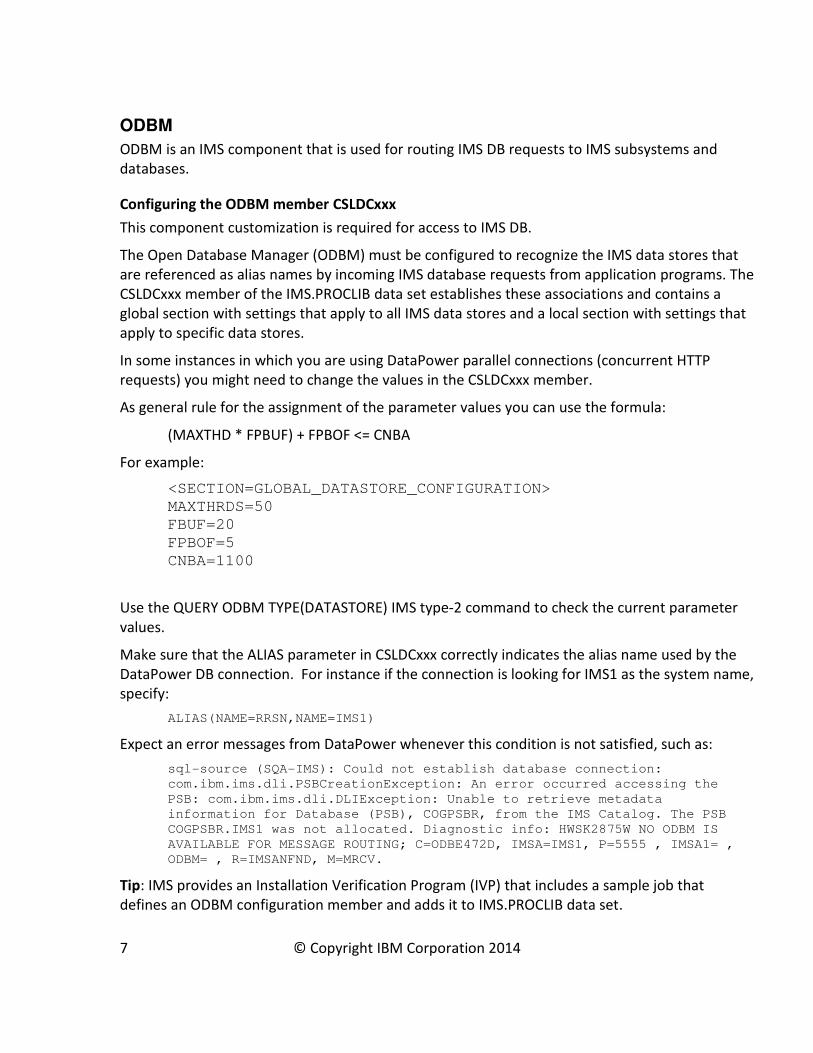
As general rule for the assignment of the parameter values you can use the formula:
(MAXTHD * FPBUF) + FPBOF <= CNBA
For example:
<SECTION=GLOBAL_DATASTORE_CONFIGURATION>
MAXTHRDS=50
FBUF=20
FPBOF=5
CNBA=1100
Use the QUERY ODBM TYPE(DATASTORE) IMS type-2 command to check the current parameter
values.
Make sure that the ALIAS parameter in CSLDCxxx correctly indicates the alias name used by the
DataPower DB connection. For instance if the connection is looking for IMS1 as the system name,
specify:
ALIAS(NAME=RRSN,NAME=IMS1)
Expect an error messages from DataPower whenever this condition is not satisfied, such as:
sql-source (SQA-IMS): Could not establish database connection:
com.ibm.ims.dli.PSBCreationException: An error occurred accessing the
PSB: com.ibm.ims.dli.DLIException: Unable to retrieve metadata
information for Database (PSB), COGPSBR, from the IMS Catalog. The PSB
COGPSBR.IMS1 was not allocated. Diagnostic info: HWSK2875W NO ODBM IS
AVAILABLE FOR MESSAGE ROUTING; C=ODBE472D, IMSA=IMS1, P=5555 , IMSA1= ,
ODBM= , R=IMSANFND, M=MRCV.
Tip: IMS provides an Installation Verification Program (IVP) that includes a sample job that
defines an ODBM configuration member and adds it to IMS.PROCLIB data set.
7 © Copyright IBM Corporation 2014
For more information, see CSLDCxxx member of the IMS PROCLIB data set in the IMS
documentation at
http://www.ibm.com/support/knowledgecenter/SSEPH2_13.1.0/com.ibm.ims13.doc.sdg/ims_csl
dcxxx_proclib.htm.
IMS Catalog
This component is required for access to IMS DB. The IMS Catalog, which is new in IMS Version
12, contains metadata about the program and database resources in IMS and simplifies
distributed access to IMS databases.
In conjunction with a deployed Universal driver, a DataPower appliance uses metadata fetched
from the IMS catalog to determine the IMS data format.
IMS Catalog information is also used to verify that the IMS PSB specified in the DataPower “SQL
Data Source” definitions is valid.
8 © Copyright IBM Corporation 2014
Components in the DataPower environment
Depending on which type of DataPower support you are implementing, the DataPower
components that you need to configure are different and can include:
• A Multi-protocol gateway, which is required for all types of IMS support
• An IMS Callout Front Side Handler to support synchronous callout requests from IMS
applications to data or services on the DataPower backside
• DataPower IMS DB support for access to IMS databases
• The separately licensed DataPower SQL Data Source for access to IMS databases
• If data transformation is required, a data transformation map or a stylesheet. Use
WebSphere® Transformation Extender Design Studio to create data transformation maps.
You must code stylesheets yourself.
• An IMS Connect object for access to IMS transactions and application programs in an IMS
TM provider scenario
Multi-protocol gateway
A Multi-Protocol Gateway connects client requests that are transported over one or more
protocols to a remote destination that uses the same or a different protocol. The Multi-Protocol
Gateway supports the FTP, HTTP, HTTPS, IMS™, MQ, NFS, SFTP, TIBCO EMS, and WebSphere®
JMS protocols.
A Multi-Protocol Gateway offers many of the same services and capabilities as a Web Service
Proxy. Unlike a Web Service Proxy, a Multi-Protocol Gateway cannot use a WSDL to determine
the configuration.
A Multi-Protocol Gateway is required for each type of IMS support.
You can configure multiple Multi-Protocol Gateways.
A Multi-Protocol Gateway includes the following capabilities:
• Implement Reliable Messaging policies
• Implement WS-Addressing protocol enforcement
• Accept and send SOAP, raw XML, or unprocessed (binary) documents
• Transform XML to binary format documents and binary format documents to ML
• Filter, validate, transform, encrypt, or decrypt XML documents
• Route XML documents
• Sign documents or verify signatures
• Process large documents in the streaming mode
9 © Copyright IBM Corporation 2014
• Implement document-level security or service-level security
• Communicate with clients, servers, and peers with SSL encryption
• Monitor and control data traffic based on request sources and requested resources
• Allow, reject, strip, or process attachments (MIME, DIME, MTOM)
IMS Callout Front Side Handler for synchronous callout support
The IMS Callout handler of the DataPower Multi-Protocol Gateway retrieves IMS callout request
messages from an IMS application and sends the callout response data back to the IMS
application.
WebSphere Transformation Extender data transformation maps
Using WebSphere® Transformation Extender Design Studio is recommended to create the data
transformation maps that are required to transform IMS synchronous callout requests into the
data format that is used by the data or service provider on the DataPower backend. After the
transformation, the DataPower appliance can perform other processing actions (validate,
transform, route) on the XML message. The DataPower appliance can also use maps to transform
message data from XML to binary.
Design Studio can be used in combination with any IBM WebSphere DataPower appliance that
has the DataGlue license to perform the following tasks:
• Create data objects to define the structure of your data, including source and target data
structures
• Develop maps to define the logic for data transformation
• Test and deploy maps to appliance
For more information, see the WebSphere Transformation Extender documentation at
http://www.ibm.com/support/knowledgecenter/SSVSD8/welcome.
SQL Data Source for access to IMS DB
An SQL Data Source provides the configuration to establish a direct connection to an IMS
database. When configured, it is possible to dynamically perform database operations, such
as basic CRUD1 operations, on the IMS database.
The DataPower SQL-ODBC component requires a dedicated license. You can view your available
licenses by doing a ‘show license’ from the command line interface (CLI).
In the Web GUI, click Status and under the System header, click Device Features to see what you
are licensed to use, and Library Information to see what licensed features are currently installed.
1 CRUD refers to the four basic functions of persistent storage: create, read, update and delete. It is used here to
describe the user interface conventions that facilitate viewing, searching, and changing information in relational DB
application (insert, select, update, delete).
10 © Copyright IBM Corporation 2014

IMS Connect object for access to IMS TM
The DataPower IMS™ Connect object handles IMS protocol communications from a DataPower®
service to IMS applications. The configuration of the IMS Connect object defines the behavior of
the connection to IMS TM.
11 © Copyright IBM Corporation 2014
Working with DataPower appliancesThis section contains general information about working with DataPower appliances.
DataPower user interfaces
You can use either one of two interfaces for configuring and managing your DataPower
appliance:
• Command line interface
• Web GUI
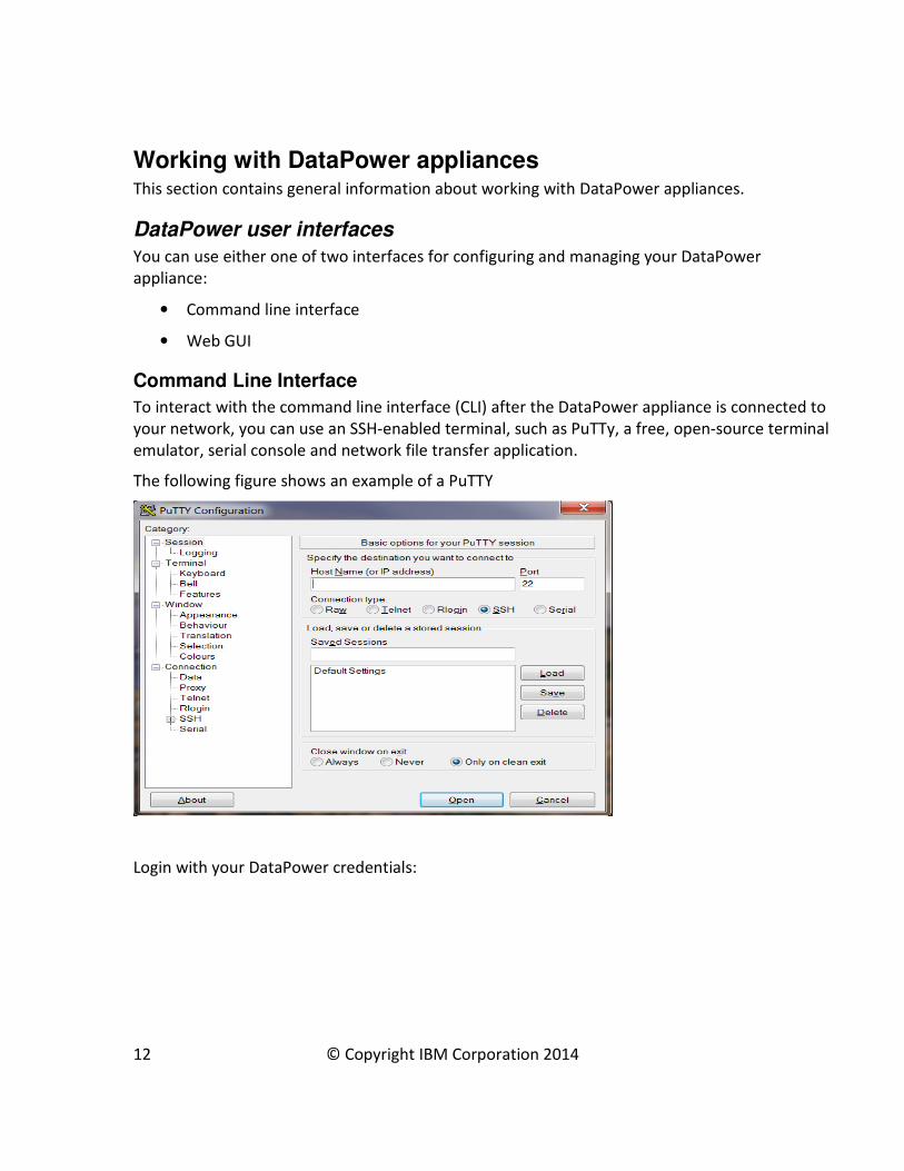
Command Line Interface
To interact with the command line interface (CLI) after the DataPower appliance is connected to
your network, you can use an SSH-enabled terminal, such as PuTTy, a free, open-source terminal
emulator, serial console and network file transfer application.
The following figure shows an example of a PuTTY
Login with your DataPower credentials:
12 © Copyright IBM Corporation 2014
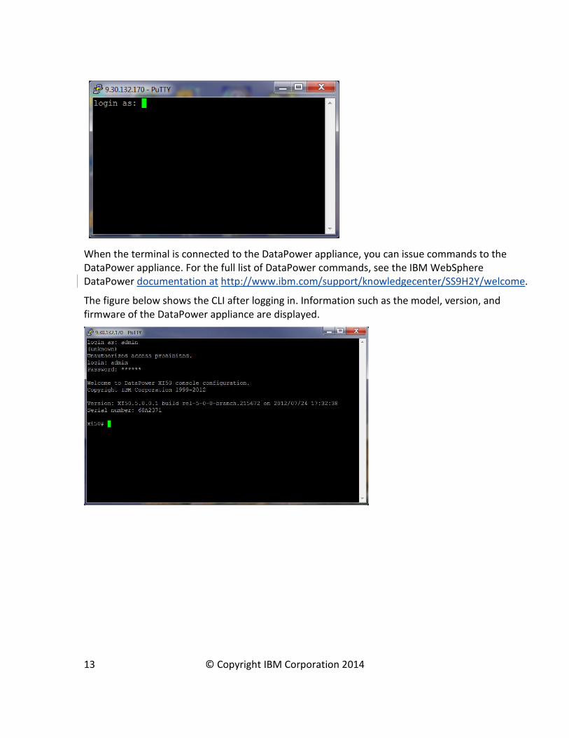
When the terminal is connected to the DataPower appliance, you can issue commands to the
DataPower appliance. For the full list of DataPower commands, see the IBM WebSphere
DataPower documentation at http://www.ibm.com/support/knowledgecenter/SS9H2Y/welcome.
The figure below shows the CLI after logging in. Information such as the model, version, and
firmware of the DataPower appliance are displayed.
13 © Copyright IBM Corporation 2014
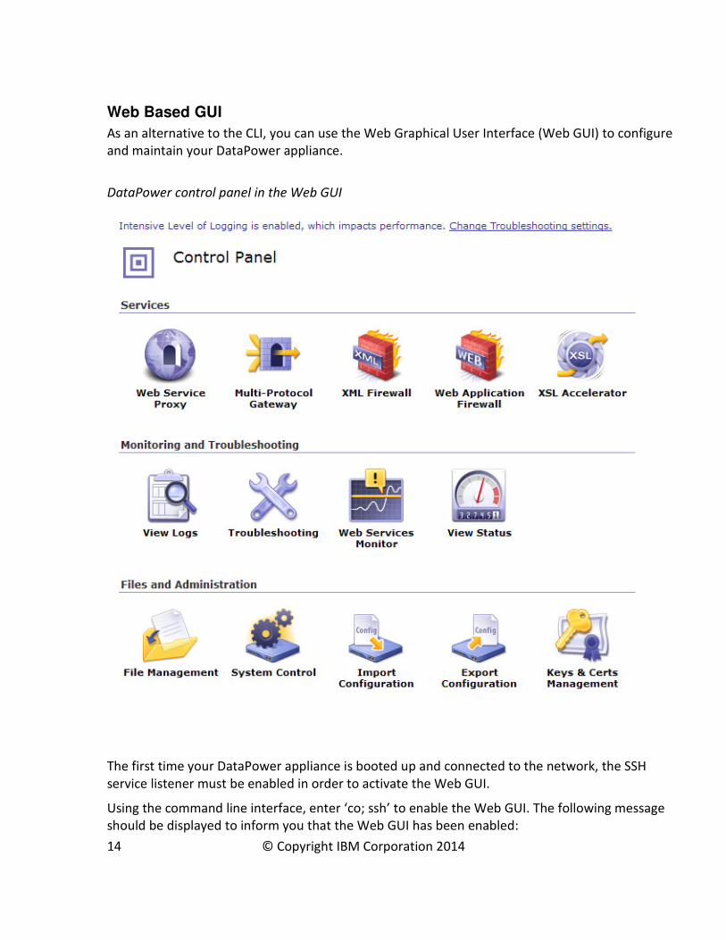
Web Based GUI
As an alternative to the CLI, you can use the Web Graphical User Interface (Web GUI) to configure
and maintain your DataPower appliance.
DataPower control panel in the Web GUI
The first time your DataPower appliance is booted up and connected to the network, the SSH
service listener must be enabled in order to activate the Web GUI.
Using the command line interface, enter ‘co; ssh’ to enable the Web GUI. The following message
should be displayed to inform you that the Web GUI has been enabled:
14 © Copyright IBM Corporation 2014

Xi52# co;ssh
Global configuration mode
SSH service listener enabled
Entering ‘show web-mgmt’ in the CLI, displays information about your Web GUI properties.
Open a web browser and enter the following URL in the address field to display the Web GUI:
https://<DataPower IP>:<DataPower port>
The Login dialog opens:
Upon submitting your login information, the main control panel is displayed.
Tip: Multiple appliances can be managed together as part of a set through the use of IBM Tivoli
Composite Appliance Management System Edition for WebSphere DataPower (ITCAMSE for
WDP).
15 © Copyright IBM Corporation 2014
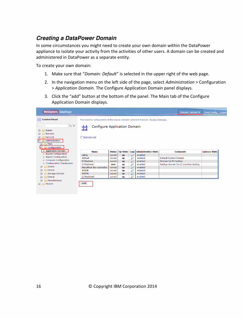
Creating a DataPower Domain
In some circumstances you might need to create your own domain within the DataPower
appliance to isolate your activity from the activities of other users. A domain can be created and
administered in DataPower as a separate entity.
To create your own domain:
1. Make sure that “Domain: Default” is selected in the upper right of the web page.
2. In the navigation menu on the left side of the page, select Administration > Configuration
> Application Domain. The Configure Application Domain panel displays.
3. Click the “add” button at the bottom of the panel. The Main tab of the Configure
Application Domain displays.
16 © Copyright IBM Corporation 2014

Upgrading DataPower Firmware
If you have an older DataPower appliance, such as the XI50, your appliance might be able to
support IMS synchronous callout requests or access to IMS transactions or databases if you
update the firmware.
Note: Updating firmware requires a restart of the DataPower appliance.
To check for available firmware upgrades, see the Supported firmware versions and
recommended upgrade levels for IBM WebSphere DataPower SOA Appliances web page at
http://www-01.ibm.com/support/docview.wss?uid=swg21237631.
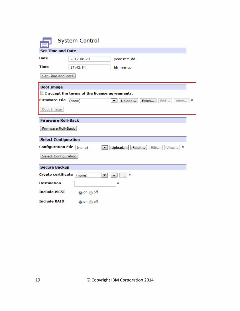
To update the firmware:
1) Control Panel -> System Control
17 © Copyright IBM Corporation 2014

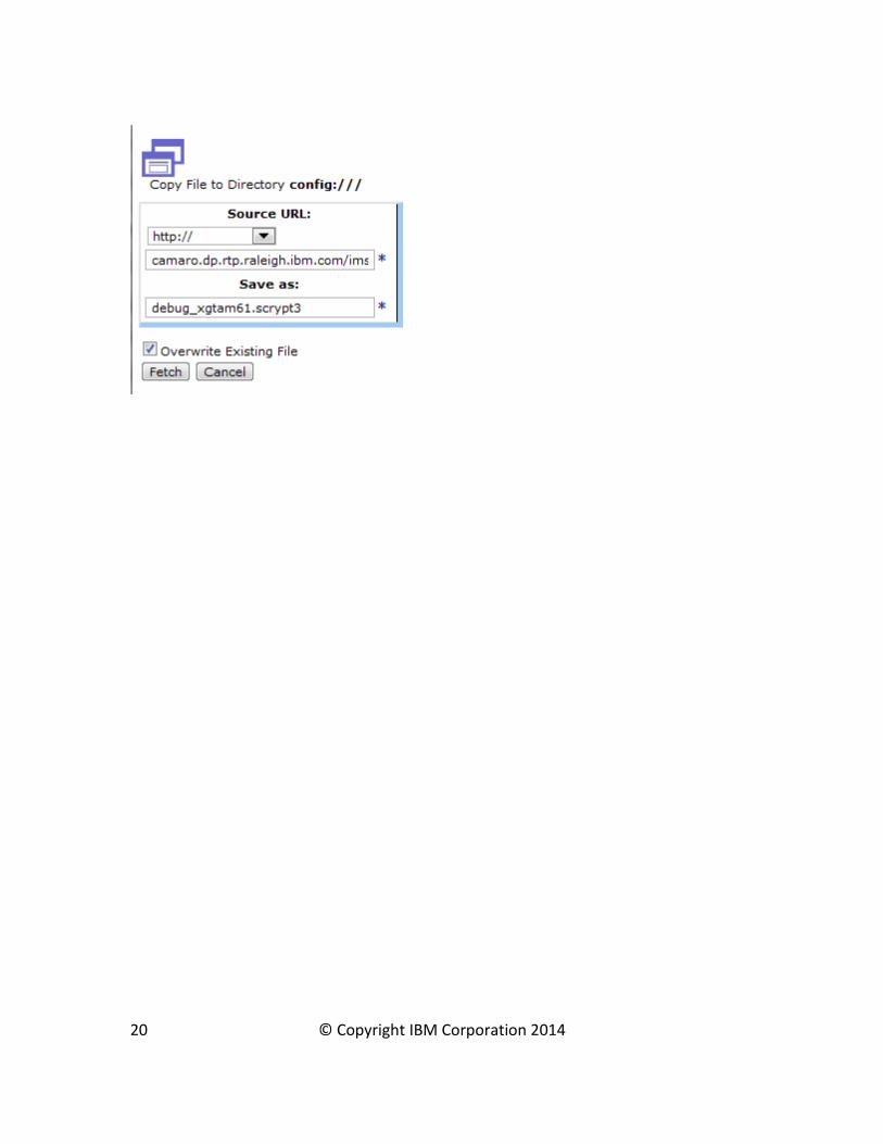
2) Under "Boot Image" click "Fetch..."
3) In the popup window enter the firmware URL
4) Click anywhere on the screen to let the other fields be auto-filled
5) Check "Overwrite Existing File" if necessary. Click "Fetch"
6) Click "Boot Image" in the System Control panel
7) 6) Wait for DataPower to reboot
The whole process takes 5-10 minutes.
18 © Copyright IBM Corporation 2014
19 © Copyright IBM Corporation 2014
20 © Copyright IBM Corporation 2014
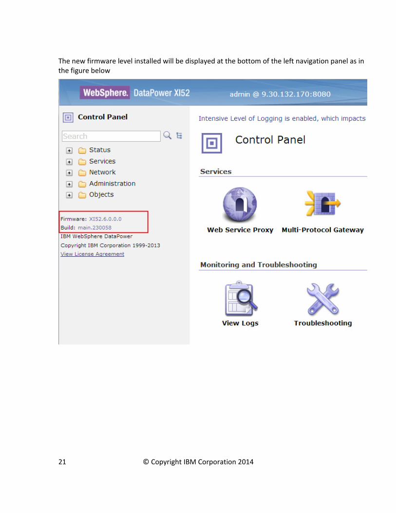
The new firmware level installed will be displayed at the bottom of the left navigation panel as in
the figure below
21 © Copyright IBM Corporation 2014

Configuring the Synchronous Callout SolutionTo configure DataPower and IMS to support access to the IMS TM server, you need to configure
components in both the IMS and DataPower environments:
In the IMS environment, you need to configure:
• OTMA
• IMS Connect
• The ICAL call of the IMS DL/I API
In the DataPower environment, you need to configure:
• The Multi-Protocol Gateway
• The IMS Callout Front Side Handler
• The connection between DataPower and the backend service provider
• Define the Multi-Protocol Gateway processing policies and rules that determine the actions that
DataPower takes the callout requests and responses that it handles.
Configuring IMS components for IMS synchronous callout requests
To support access to IMS TM from DataPower, the configuration steps in IMS are generally the
same as they are for configuring access to IMS TM from any other IMS Connect client: you need
to enable OTMA if it is not already enabled, and configure IMS Connect.
Configuring OTMA for Synchronous Callout support
To support synchronous callout, OTMA must be enabled in IMS and an OTMA destination
descriptor must be defined that routes the callout requests through IMS Connect and the
DataPower appliance.
Enabling OTMA
To enable IMS™ to use OTMA, specify the z/OS® cross-system coupling facility (XCF) group name
and IMS OTMA member name during system definition.
OTMA is installed with IMS TM. The IMS INSTALL/IVP Dialog is not used to install OTMA.
To start OTMA, you can use the OTMA=Y startup parameter in the IMS procedure during IMS
system definition or, after an IMS restart, issue the type-1 command /START OTMA.
Defining an OTMA destination descriptor for synchronous callout support
An OTMA destination descriptor defines an output destination, or TPIPE, for IMS output
messages, such as synchronous callout messages. The DataPower IMS Callout front side handler
22 © Copyright IBM Corporation 2014

retrieves synchronous callout messages from IMS by listening on the TPIPE specified on the
OTMA destination descriptor.
You can also use the OTMA destination descriptor to specify a timeout value for synchronous
callout requests. If a timeout value is specified in both the OTMA destination descriptor and in
the DL/I ICAL call itself, the lesser of the two values is used.
OTMA destination descriptors can be created, modified, or deleted while IMS is running by using
IMS type-2 commands, or they can be coded during IMS system definition and stored in the
DFSYDTx member of the IMS.PROCLIB data set. However, IMS must be restarted to recognize any
new or changed OTMA destination descriptors that are coded in the DFSYDTx member.
Here is an example of an OTMA destination descriptor:
D OTMDSC01 TYPE=IMSCON TMEMBER=HWS1 TPIPE=TPIPE1
D OTMDSC02 TYPE=IMSCON TMEMBER=HWS1 TPIPE=TPIPE2
D OTMDSC03 TYPE=IMSCON TMEMBER=HWS1 TPIPE=TPIPE3
Note: The tpipes must be dedicated to DataPower and the synchronous callout requests sent to a
particular service. The tpipes cannot be shared with any other application or solution, such as IMS
SOAP Gateway. If a TPIPE is shared, either DataPower or the other solution might be unable to
retrieve the synchronous callout requests properly.
For IMS Version 13 information about OTMA destination descriptors, see
http://www.ibm.com/support/knowledgecenter/SSEPH2_13.1.0/com.ibm.ims13.doc.ccg/ims_ot
ma_admin_006.htm.
For IMS Version 13 information about the CREATE OTMADESC command and its keywords, see
CREATE OTMADESC command at
http://www.ibm.com/support/knowledgecenter/SSEPH2_13.1.0/com.ibm.ims13.doc.cr/imscmds
/ims_createotmadesc.htm.
For IMS Version 13 information about coding OTMA destination descriptors, see OTMA
destination descriptor syntax and parameters in the IMS documentation at
http://www.ibm.com/support/knowledgecenter/SSEPH2_13.1.0/com.ibm.ims13.doc.sdg/ims_dfs
ydtx_proclib_dest_dscrp.htm.
Configuring IMS Connect for Synchronous Callout support
IMS Connect must be configured for IMS TM access with:
• A DATASTORE configuration statement
• The IBM WebSphere DataPower message exit routine (HWSDPWR1)
An IMS Connect DATASTORE statement defines a connection between IMS Connect and IMS TM.
It is required for synchronous callout support and is in addition to the HWS and TCPIP statements
that are required for all types of IMS Connect support. All of the IMS Connect configuration
statements are defined in the HWSCFGxxx member of the IMS.PROCLIB data set.
23 © Copyright IBM Corporation 2014
The value of the ID keyword in the DATASTORE statement is the value that is specified in
DataPower in the Data store field when you configure the IMS Callout front-side handler.
The port number on which IMS Connect listens for DataPower is defined in the TCPIP
configuration statement on the PORT or PORTID keyword.
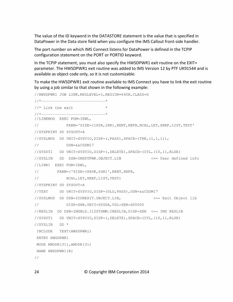
In the TCPIP statement, you must also specify the HWSDPWR1 exit routine on the EXIT=
parameter. The HWSDPWR1 exit routine was added to IMS Version 12 by PTF UK91544 and is
available as object code only, so it is not customizable.
To make the HWSDPWR1 exit routine available to IMS Connect you have to link the exit routine
by using a job similar to that shown in the following example:
//HWSDPWR1 JOB LINK,MSGLEVEL=1,REGION=640K,CLASS=G
//*----------------------------*
//* Link the exit *
//*----------------------------*
//LINKMOD EXEC PGM=IEWL,
// PARM='SIZE=(180K,28K),RENT,REFR,NCAL,LET,XREF,LIST,TEST'
//SYSPRINT DD SYSOUT=A
//SYSLMOD DD UNIT=SYSVIO,DISP=(,PASS),SPACE=(TRK,(1,1,1)),
// DSN=&&CSDM17
//SYSUT1 DD UNIT=SYSVIO,DISP=(,DELETE),SPACE=(CYL,(10,1),RLSE)
//SYSLIN DD DSN=IMSDTPWR.OBJECT.LIB <== User defined info
//LINK1 EXEC PGM=IEWL,
// PARM=('SIZE=(880K,64K)',RENT,REFR,
// NCAL,LET,XREF,LIST,TEST)
//SYSPRINT DD SYSOUT=A
//TEXT DD UNIT=SYSVIO,DISP=(OLD,PASS),DSN=&&CSDM17
//SYSLMOD DD DSN=ICONEXIT.OBJECT.LIB, <== Exit Object lib
// DISP=SHR,UNIT=SYSDA,VOL=SER=SDV000
//RESLIB DD DSN=IMSBLD.I12STSMM.CRESLIB,DISP=SHR <== IMS RESLIB
//SYSUT1 DD UNIT=SYSVIO,DISP=(,DELETE),SPACE=(CYL,(10,1),RLSE)
//SYSLIN DD *
INCLUDE TEXT(HWSDPWR1)
ENTRY HWSDPWR1
MODE RMODE(31),AMODE(31)
NAME HWSDPWR1(R)
//
24 © Copyright IBM Corporation 2014
Coding the ICAL call for synchronous callout requests
The ICAL call of the IMS DL/I API is how an application program running in an IMS TM dependent
region makes a synchronous callout request to a data or service provider on the DataPower
backend.
You need to code the application programs to build and issue the ICAL call. The fields of the ICAL
call are defined by an application interface block (AIB). In the AIB fields, the application program
specifies the attributes and content of the callout request, including:
• The name of the OTMA destination descriptor.
• Optionally, a time out value in 100ths of a second.
• The length of the request data.
• The length of the response data.
• The 1- to 8-byte map name, left justified in the AIBUTKN field of the AIB. This ID is
included in the state data section of the OTMA prefix in the callout message. This ID can
be used as a unique service identifier for data transformation mapping and service
routing. In DataPower, this ID appears with the callout request as the ims-callout-service-
id request header.
When a timeout value for a synchronous callout request is specified in both the OTMA
destination descriptor and in the DL/I ICAL call itself, IMS uses the lower of the two values.
Synchronous callout messages sent from IMS by using the ICAL call do not use the IMS message
queues. Consequently, synchronous callout messages are not constrained to the 32K message
segment restriction that is imposed by the IMS message queue.
For a description of the parameter fields of an ICAL call and the valid values, see ICAL call in the
IMS documentation at
http://www.ibm.com/support/knowledgecenter/SSEPH2_13.1.0/com.ibm.ims13.doc.apr/ims_ica
lcalltm.htm.
Configuring DataPower for IMS synchronous callout requests
To configure DataPower to support synchronous callout requests from IMS to a data or service
provided on the DataPower backside, you need to perform the following steps:
1. Configure the Multi-Protocol Gateway.
2. Configure IMS Callout Front Side Handler.
3. Configure the connection between DataPower and the backend external service provider.
4. Define the Multi-Protocol Gateway processing policies and rules that determine the actions that
DataPower takes the callout requests and responses that it handles.
5. Apply the changes, and save the configuration
25 © Copyright IBM Corporation 2014

The following figure illustrates a DataPower configuration that supports IMS synchronous callout
requests.
26 © Copyright IBM Corporation 2014

1. Configuring the Multi-Protocol Gateway for synchronous callout support
To configure the Multi-Protocol Gateway, start from the DataPower Control Panel and select
Multi-protocol Gateway as in fig x below, and click on “add”.
27 © Copyright IBM Corporation 2014

In the “Configure Multi-Protocol Gateway” panel, specify a Multi-Protocol Gateway name.
Toward the bottom of the panel, you must set the request type and response type. Request type
defines the traffic between IMS and DataPower on the front end. Response type defines the
traffic between the service provider and DataPower on the back end. Specify Non-XML for both
request type and response type.
More Advanced settings, such as timeout values for front- and back-side connections, are
available under the Advanced tab, as shown in the following figure.
28 © Copyright IBM Corporation 2014
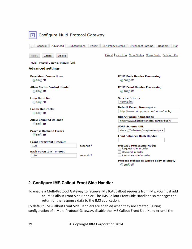
2. Configure IMS Callout Front Side Handler
To enable a Multi-Protocol Gateway to retrieve IMS ICAL callout requests from IMS, you must add
an IMS Callout Front Side Handler. The IMS Callout Front Side Handler also manages the
return of the response data to the IMS application.
By default, IMS Callout Front Side Handlers are enabled when they are created. During
configuration of a Multi-Protocol Gateway, disable the IMS Callout Front Side Handler until the
29 © Copyright IBM Corporation 2014
Multi-Protocol Gateway and the backend service is ready to service requests. Otherwise, any
callout requests sent to the IMS Callout Front Side Handler will get an error.
Also, if an IMS Callout Front Side Handler is enabled while the Multi-Protocol Gateway is being
configured, each time you apply changes by clicking the Apply button, the Multi-Protocol
Gateway effectively restarts the IMS Callout Front Side Handler and performs teardown and
resume tpipe operations. When the Multi-Protocol Gateway is ready, you can enable the IMS
Callout Front Side Handler to start the retrieval of IMS ICAL requests.
You can configure one or more IMS Callout Front Side Handlers in a single Multi-Protocol
Gateway. For each front-side handler for IMS Callout support, you can configure one or more
TPIPEs on the same IMS Connect host and port, and same IMS data store.
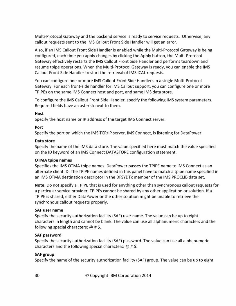
To configure the IMS Callout Front Side Handler, specify the following IMS system parameters.
Required fields have an asterisk next to them.
Host
Specify the host name or IP address of the target IMS Connect server.
Port
Specify the port on which the IMS TCP/IP server, IMS Connect, is listening for DataPower.
Data store
Specify the name of the IMS data store. The value specified here must match the value specified
on the ID keyword of an IMS Connect DATASTORE configuration statement.
OTMA tpipe names
Specifies the IMS OTMA tpipe names. DataPower passes the TPIPE name to IMS Connect as an
alternate client ID. The TPIPE names defined in this panel have to match a tpipe name specified in
an IMS OTMA destination descriptor in the DFSYDTx member of the IMS.PROCLIB data set.
Note: Do not specify a TPIPE that is used for anything other than synchronous callout requests for
a particular service provider. TPIPEs cannot be shared by any other application or solution. If a
TPIPE is shared, either DataPower or the other solution might be unable to retrieve the
synchronous callout requests properly.
SAF user name
Specify the security authorization facility (SAF) user name. The value can be up to eight
characters in length and cannot be blank. The value can use all alphanumeric characters and the
following special characters: @ # $.
SAF password
Specify the security authorization facility (SAF) password. The value can use all alphanumeric
characters and the following special characters: @ # $.
SAF group
Specify the name of the security authorization facility (SAF) group. The value can be up to eight
30 © Copyright IBM Corporation 2014

characters in length and cannot be blank. The value can use all alphanumeric characters and the
following special characters: @ # $.
Retry attempts
Specify the number of times to attempt to resume a transaction pipe (tpipe) after processing
encounters an error. Enter a value in the range 1 - 256. The default value is 5.
Retry interval
Specify the number of seconds to wait before processing attempts to resume the transaction
pipe (tpipe). The minimum value is 1. The default value is 3.
31 © Copyright IBM Corporation 2014

Connection timeout
Specify the number of seconds that the appliance waits to establish a connection to IMS Connect.
A value of 0 disables the timeout. The default value is 10.
32 © Copyright IBM Corporation 2014

More advanced settings, such as tracing and connection timeout values, are available in the
“Advanced” tab.
After you are done configuring the IMS Callout Front Side Handler, click ‘Apply’ on the Front Side
Handler panel and the Front Side Handler is enabled.
The status indicator shows the status of the Front Side Handler:
[up]: The IMS Callout Front Side Handler is enabled and is able to communicate with IMS
Connect and IMS to actively process resume tpipe. If the IMS Callout Front Side Handler
encountered an error, it attempts to retry at specified intervals, up to a specified maximum
number of retry attempts before going into [down-pending] status.
[down - pending]: The IMS Callout Front Side Handler is enabled but is in recovery mode.
The Front Side Handler attempts to ping IMS Connect every 60 seconds to re-establish a
connection. It will go into [up] mode when it can get a successful response from /DIS OTMA
command to verify both IMS and IMS Connect are responding.
[down - disabled]: The IMS Callout Front Side Handler is disabled.
33 © Copyright IBM Corporation 2014

3. Configuring the backend destination
Under the “General Configuration” tab, you specify the address of the service provider that will
process the callout request on the DataPower backend.
Addresses of the backend service providers can be specified statically or dynamically. If the IMS
Callout requests will be processed by a single backend service provider, use a static backend. If
the IMS callout requests will be distributed to multiple addresses for backend service providers,
use a dynamic backend.
3a. Dynamically defined backend addresses
To specify dynamically defined backend addressing:
1. Select the dynamic-backend radio button under Type.
2. Define the addresses and routing logic in a stylesheet (XSLT) inside a Filter Action within
the Multi-Protocol Gateway policy.
34 © Copyright IBM Corporation 2014

3b. Static backend
To specify a static backend service provider:
1. Select the static-backend radio button under Type.
2. Type the URL of the service provider into the Default Backend URL field. Routing logic is
not required and you do not need to specify a stylesheet.
3b. Adding an echo HTTP Service on the backend for testing purposes
While configuring the communication between IMS and DataPower, you can create an echo HTTP
service to unit test the Multi-Protocol Gateway. The echo HTTP service emulates a backend
connection with a server. With an echo service as the backend handler, the request message is
returned to IMS unchanged as the response message.
35 © Copyright IBM Corporation 2014
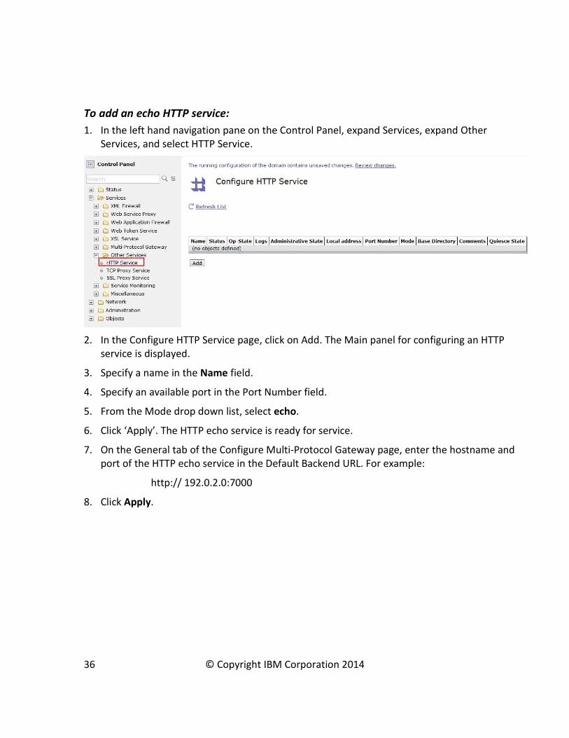
To add an echo HTTP service:
1. In the left hand navigation pane on the Control Panel, expand Services, expand Other
Services, and select HTTP Service.
2. In the Configure HTTP Service page, click on Add. The Main panel for configuring an HTTP
service is displayed.
3. Specify a name in the Name field.
4. Specify an available port in the Port Number field.
5. From the Mode drop down list, select echo.
6. Click ‘Apply’. The HTTP echo service is ready for service.
7. On the General tab of the Configure Multi-Protocol Gateway page, enter the hostname and
port of the HTTP echo service in the Default Backend URL. For example:
http:// 192.0.2.0:7000
8. Click Apply.
36 © Copyright IBM Corporation 2014

37 © Copyright IBM Corporation 2014

4. Defining a Processing Policy for the Multi-Protocol Gateway
A processing policy defines many, if not all, of the actions that are taken against the
messages that pass through the Multi-Protocol Gateway service.
• A processing policy consists of one or more rules.
• A rule consists of a matching rule and a processing rule.
• A matching rule defines the criteria to determine whether incoming traffic is
processed by its processing rule.
• A processing rule identifies the actions to perform against the incoming traffic.
To access the configuration panel for defining processing policies, from the Configure Multi-
Protocol Gateway panel, click on the “+” button under Multi-Protocol Gateway Policy.
38 © Copyright IBM Corporation 2014

In the Configure Multi-Protocol Gateway Style Policy panel, a rule is depicted as a line with
symbols on it, as shown in the following figure. Each rule consists of a Matching Rule, which
determines whether or not to process the incoming data, a Results Action, and one or more
processing actions in between; each rule can be configured to flow from client to server, vice-
versa, or in both directions.
4a. Configuring a Matching Rule
A matching rule determines whether and how to process incoming data.
A matching rule is represented by a Match Action icon, . A Match Action icon is automatically
placed on the rule line when you create your policy rule:
39 © Copyright IBM Corporation 2014

Double click on the Match Action icon to define the match rule. Click on the “+” button to add a
new Matching Rule; click on “…” to edit an existing one.
Click the “Matching Rule” tab to add a new URL match pattern:
40 © Copyright IBM Corporation 2014
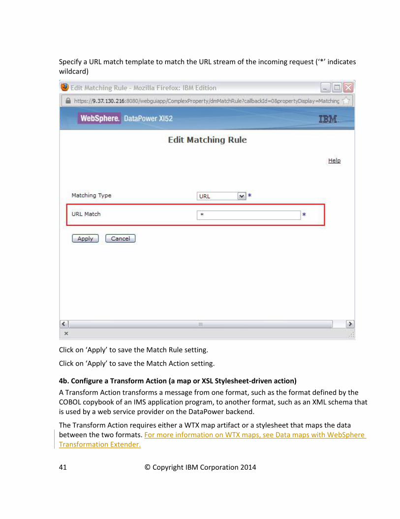
Specify a URL match template to match the URL stream of the incoming request (‘*’ indicates
wildcard)
Click on ‘Apply’ to save the Match Rule setting.
Click on ‘Apply’ to save the Match Action setting.
4b. Configure a Transform Action (a map or XSL Stylesheet-driven action)
A Transform Action transforms a message from one format, such as the format defined by the
COBOL copybook of an IMS application program, to another format, such as an XML schema that
is used by a web service provider on the DataPower backend.
The Transform Action requires either a WTX map artifact or a stylesheet that maps the data
between the two formats. For more information on WTX maps, see Data maps with WebSphere
Transformation Extender.
41 © Copyright IBM Corporation 2014

A stylesheet can also be used in a Transform Action to select between multiple WTX maps or to
route the message to a backend destination by using request header values. For example, you
can optionally access the values in the ims-callout-correlation-token and ims-callout-service-id
headers of each IMS Callout request.
The ims-callout-correlation-token header contains a hexadecimal representation of the unique
ICAL correlation token of the IMS callout request. This token contains the user ID for the request.
The ims-callout-service-id header contains the 8-byte map name that is specified in the AIBUTKN
field in the AIB of the IMS ICAL call.
The ims-callout-user-id header contains the 8-byte user ID that is associated with the IMS
application that issues a callout request. The user ID is extracted from the correlation token.
To dynamically direct a request to a backend URL, you can specify a target URL with the
var://service/routing-url variable and make the routing decision by using the value of the ims-
callout-service-id header. For example, in the following Sample XSL style sheet, if the value of
header is SERVICE1, the request is sent to the backend server on port 6221, but if the header
value is SERVICE2, the request is sent to the backend server on port 6222.
To dynamically select a particular WTX map, you can specify a target WTX map with the
var://context/map/name variable and make the selection decision based on the ims-callout-
service-id value. For example, in the following Sample XSL stylesheet, if the header value is
SERVICE1, the WTX map request-250-cp037.dpa is used, but if the header value is SERVICE2, the
WTX map request-8000-cp037.dpa is used.
A stylesheet can also use these values for diagnostic purposes. For example, in following Sample
XSL stylesheet, if an error occurs in the transform action, the IMS correlation token and service ID
is written out to the system log with error level.
Sample XSL:
<?xml version="1.0" encoding="UTF-8"?>
<xsl:stylesheet version="1.0"
xmlns:xsl="http://www.w3.org/1999/XSL/Transform"
xmlns:dp="http://www.datapower.com/extensions"
extension-element-prefixes="dp">
<xsl:template match='/'>
<xsl:variable name="be"
select="dp:request-header('ims-callout-service-id')"/>
42 © Copyright IBM Corporation 2014

<xsl:choose>
<xsl:when test="$be = 'SERVICE1'">
<dp:set-variable name="'var://context/map/name'"
value="'local://request-250-cp037.dpa'" />
<dp:set-variable name="'var://service/routing-url'"
value="'http:// 192.0.2.0:6221'" />
</xsl:when>
<xsl:when test="$be = 'SERVICE2'">
<dp:set-variable name="'var://context/map/name'"
value="'local://request-8000-cp037.dpa'" />
<dp:set-variable name="'var://service/routing-url'"
value="'http:// 192.0.2.0:6222'" />
</xsl:when>
<xsl:otherwise>
<dp:reject>unknown backend specified</dp:reject>
</xsl:otherwise>
</xsl:choose>
<xsl:message dp:priority="error">
Correlation token : <xsl:value-of
select="dp:request-header('ims-callout-correlation-token')"/>
</xsl:message>
<xsl:message dp:priority="error">
Service ID : <xsl:value-of
select="dp:request-header('ims-callout-service-id')"/>
</xsl:message>
43 © Copyright IBM Corporation 2014
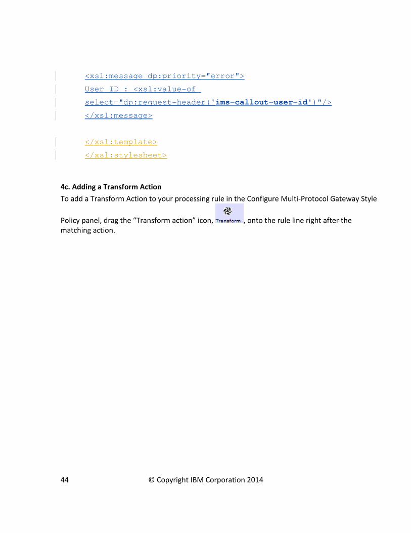
<xsl:message dp:priority="error">
User ID : <xsl:value-of
select="dp:request-header('ims-callout-user-id')"/>
</xsl:message>
</xsl:template>
</xsl:stylesheet>
4c. Adding a Transform Action
To add a Transform Action to your processing rule in the Configure Multi-Protocol Gateway Style
Policy panel, drag the “Transform action” icon, , onto the rule line right after the
matching action.
44 © Copyright IBM Corporation 2014

The Transform Action must specify the map or stylesheet to use in order to direct the message
for data transformation and routing.
For more information about developing an XSL stylesheet, see Using WebSphere DataPower SOA
Appliances to enable the Information as a Service pattern on developerWorks at
http://www.ibm.com/developerworks/websphere/library/techarticles/0812_callaway/0812_call
away.html.
An XSL stylesheet must be stored locally on your workstation to upload it for use by the
Transform Action.
To add a Transform Rule to a Transform Action, double click on the Transform Action icon on the
line that represents your processing rule.
To specify a stylesheet or WTX map, select Use XSLT specified in this action on a non-XML
message. For an XSL style sheet, click Upload to upload an XSL style sheet file. For a WTX map,
click Upload to upload the dpa file.
Click on Done to save the Transform Action setting.
45 © Copyright IBM Corporation 2014

4d. Configure Results Action
Use a Results Action to configure a Multi-Protocol Gateway policy to return the transformed
message.
46 © Copyright IBM Corporation 2014

To configure a Results Action, drag the Results action icon, , onto the end of the line that
represents your processing rule.
Double click on the Results Action icon on the line to configure the Results Rule.
Click on ‘Done’ to save the Results Action setting.
5. Apply the changes, and save the configuration
Click ‘Apply’ on the Configure Multi-Protocol Gateway panel, then click on Save Config. The
configuration of the DataPower Multi-Protocol Gateway to support synchronous callout requests
from IMS is complete. To confirm that DataPower is processing the synchronous callout request
messages and their responses as expected, click on View Log link in the Configure Multi-Protocol
47 © Copyright IBM Corporation 2014

Gateway panel to see the log messages for the Multi-Protocol Gateway and IMS Callout Front
Side Handler.
If the log records indicate that the messages are not being processed correctly, refer to the
Troubleshooting section. If the log is not capture enough information to diagnose a problem, the
Troubleshooting section also contains information about changing the level of logging to capture
more information.
Moving an IMS Callout Front Side Handler to another Multi-Protocol Gateway
An IMS Callout Front Side Handler cannot be shared by multiple Multi-Protocol Gateways, but
you can move an existing front side handler to a different Multi-Protocol Gateway.
To move an IMS Callout Front Side Handler from one Multi-Protocol Gateway to another:
1. Delete the IMS Callout Front Side Handler from the current Multi-Protocol
Gateway
2. Save the current Multi-Protocol Gateway
3. Add the IMS Callout Front Side Handler to the destination Multi-Protocol Gateway
4. Save the destination Multi-Protocol Gateway.
Failover support for IMS Callout Front Side Handlers
For failover support, you can configure redundant IMS Callout Front Side Handlers with the same
properties to listen on the same host TPIPE. The first IMS Callout Front Side Handler on a TPIPE
has an active connection with IMS Connect, while the other IMS Callout Front Side Handlers on
the same TPIPE are queued. If the active IMS Callout Front Side Handler fails, the next one in the
queue takes over.
Testing the synchronous callout support
In order to verify that DataPower support for IMS Synchronous Callout requests is set up
correctly, you can generate a callout request by using the IMS DL/I test program, DFSDDLT0.
Before you run the DFSDDLT0 test program, be sure the following steps have been completed:
• The OTMA descriptor for the outbound routing of the synchronous callout request is
defined.
• Either the service provider that the IMS application is calling out to is set up to listen for
callout messages, or the echo HTTP service is set up in DataPower. If neither of these are
set up before the ICAL is issued, the ICAL is likely to time out, in which case IMS returns an
error to the IMS application.
48 © Copyright IBM Corporation 2014
• The DataPower Exit needs to be installed in the IMS.SDFSRESL data set.
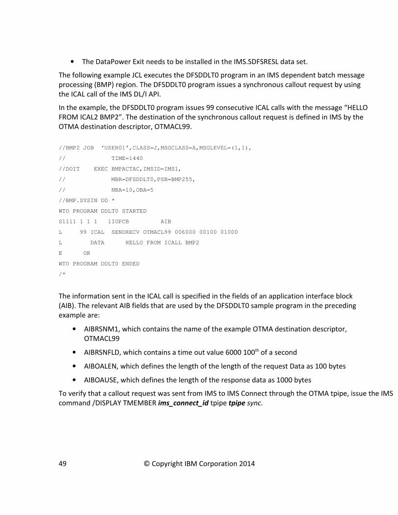
The following example JCL executes the DFSDDLT0 program in an IMS dependent batch message
processing (BMP) region. The DFSDDLT0 program issues a synchronous callout request by using
the ICAL call of the IMS DL/I API.
In the example, the DFSDDLT0 program issues 99 consecutive ICAL calls with the message “HELLO
FROM ICAL2 BMP2”. The destination of the synchronous callout request is defined in IMS by the
OTMA destination descriptor, OTMACL99.
//BMP2 JOB ‘USER01’,CLASS=J,MSGCLASS=A,MSGLEVEL=(1,1),
// TIME=1440
//DOIT EXEC BMPACTAC,IMSID=IMS1,
// MBR=DFSDDLT0,PSB=BMP255,
// NBA=10,OBA=5
//BMP.SYSIN DD *
WTO PROGRAM DDLT0 STARTED
S1111 1 1 1 1IOPCB AIB
L 99 ICAL SENDRECV OTMACL99 006000 00100 01000
L DATA HELLO FROM ICALL BMP2
E OK
WTO PROGRAM DDLT0 ENDED
/*
The information sent in the ICAL call is specified in the fields of an application interface block
(AIB). The relevant AIB fields that are used by the DFSDDLT0 sample program in the preceding
example are:
• AIBRSNM1, which contains the name of the example OTMA destination descriptor,
OTMACL99
• AIBRSNFLD, which contains a time out value 6000 100th of a second
• AIBOALEN, which defines the length of the length of the request Data as 100 bytes
• AIBOAUSE, which defines the length of the response data as 1000 bytes
To verify that a callout request was sent from IMS to IMS Connect through the OTMA tpipe, issue the IMS
command /DISPLAY TMEMBER ims_connect_id tpipe tpipe sync.
49 © Copyright IBM Corporation 2014
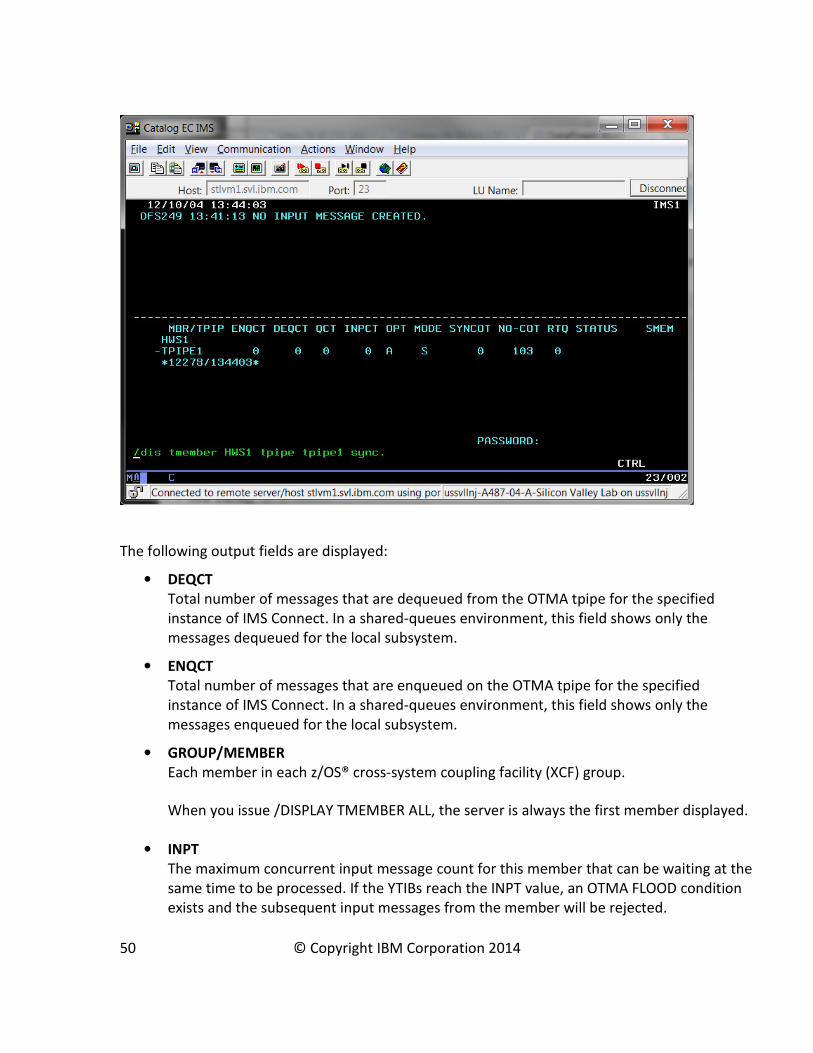
The following output fields are displayed:
• DEQCT
Total number of messages that are dequeued from the OTMA tpipe for the specified
instance of IMS Connect. In a shared-queues environment, this field shows only the
messages dequeued for the local subsystem.
• ENQCT
Total number of messages that are enqueued on the OTMA tpipe for the specified
instance of IMS Connect. In a shared-queues environment, this field shows only the
messages enqueued for the local subsystem.
• GROUP/MEMBER
Each member in each z/OS® cross-system coupling facility (XCF) group.
When you issue /DISPLAY TMEMBER ALL, the server is always the first member displayed.
• INPT
The maximum concurrent input message count for this member that can be waiting at the
same time to be processed. If the YTIBs reach the INPT value, an OTMA FLOOD condition
exists and the subsequent input messages from the member will be rejected.
50 © Copyright IBM Corporation 2014
• MODE
The resume tpipe mode, which for synchronous callout is always S
• NO-COT
The current number of ICAL messages received for this tpipe. If the number is greater
than or equal to 65535, it will be reset to 1.
• OPT
The resume tpipe option, which for synchronous callout requests to DataPower is always
A.
• QCT
Total number of messages that are still in the queue for OTMA tpipe for this instance of
IMS Connect. In a shared-queues environment, this field shows only the messages
enqueued for the local subsystem.
• RTQ
The number of queued resume tpipe requests to be processed.
Troubleshooting Synchronous Callout support
DataPower offers a variety of features for troubleshooting problems with networking, logging,
and error handling.
This section contains the following topics:
• Troubleshooting Network Connectivity
• Setting up Logging for the IMS Callout Font Side Handler
• Error Handling Considerations
• Collecting IMS Callout Trace
• Troubleshooting DataPower Web GUI timeout
• Troubleshooting Callout IMS Connect connections
Troubleshooting Network Connectivity
When diagnosing an ICAL timeout problem, it is important to first rule out a network issue. Check
your firewall settings and ensure you can ping from client to DataPower to server, and vice versa.
You access the troubleshooting options for DataPower network connectivity from the Control
Panel by clicking on Troubleshooting icon.
51 © Copyright IBM Corporation 2014

In the Networking section, you can validate network connectivity by:
• Pinging the client or server by entering the remote Host IP address and clicking Ping
Remote.
• Testing the TCP connection by entering the remote Host IP address and remote port and
clicking TCP Connection Test.
52 © Copyright IBM Corporation 2014

Setting up Logging for the IMS Callout Font Side Handler
Logging can be an excellent diagnostic tool when you need to isolate a problem or monitor a
behavior over a long period of time.
Recommendation: Enable or increase the level of logging in a DataPower and IMS configuration
only when you need to debug a problem or when you are instructed to do so by the IBM
Technical Support. While generally safe in production environments, logging can negatively affect
the performance of the DataPower appliance, especially at higher levels.
You can activate logging for the IMS Callout Font Side Handler through the Troubleshooting panel
of DataPower web GUI by the following actions:
• Configure a log category
• Configure a log target
• Event Subscription
For more information, see Troubleshooting and support in the IBM WebSphere DataPower
documentation at http://www.ibm.com/support/knowledgecenter/SS9H2Y/welcome.
53 © Copyright IBM Corporation 2014

Configuring a log category
To configure and add a log category:
1. In the left navigation bar of the DataPower web GUI, click on Objects -> Logging
Configuration -> Log Category
2. Click the Add button at the bottom of the screen.
3. Enter “ims” as the name for the log category.
Next, configure the log target.
54 © Copyright IBM Corporation 2014

Configuring a log target
To configure and add a log target:
1. In the left navigation bar of the DataPower web GUI, click on: Objects -> Logging
Configuration -> Log Target.
2. In the General Configuration section:
• Select File in the Target Type field
• Select Text in the Log Format field
3. In the Destination Configuration section, specify the location and the file name into which
DataPower will write the log messages that are generated by the IMS Callout Font Side
Handler.
4. After all of the values are set up as shown in the preceding figure, click Apply.
Next, add an event subscription.
55 © Copyright IBM Corporation 2014

Event Subscription
After defining the log category and configuring the log target, you must add an event
subscription.
1. Under the Event Subscription tab of the Configure Log Target panel, click on the Add
button. The Edit Event Subscription panel is displayed.
2. Select the event category name that you specified from a drop down menu.
3. Set the level of logging required.
4. After all the preceding steps are complete, click Apply
5. Save the configuration.
You can now activate logging for the IMS Callout Font Side Handler.
56 © Copyright IBM Corporation 2014
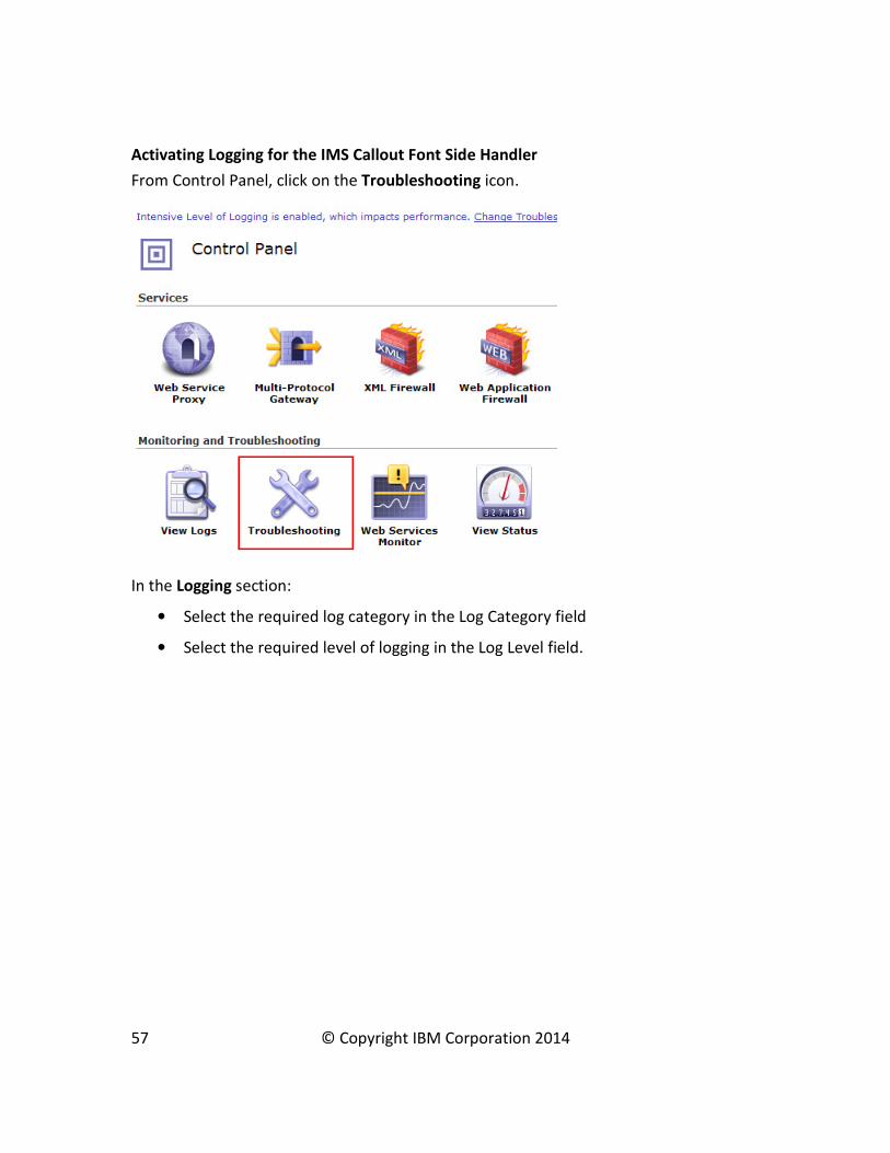
Activating Logging for the IMS Callout Font Side Handler
From Control Panel, click on the Troubleshooting icon.
In the Logging section:
• Select the required log category in the Log Category field
• Select the required level of logging in the Log Level field.
57 © Copyright IBM Corporation 2014

58 © Copyright IBM Corporation 2014

Tracing IMS Callout support
In order to diagnose complex problems, you can enable tracing in the IMS Synchronous Callout
Front side handler in addition to the multi-level logging.
Recommendation: Do not activate tracing unless requested to do so by IBM Support. Tracing can
negatively affect performance because of the volume of data that it collects.
To activate tracing:
1. In the IMS Callout front side handler configuration panel, click on the Advanced tab.
2. In the Trace file field, specify the output directory and file name for the trace. For
example, temporary://myTrace.txt. You can use the following DataPower directories as
the location when you enable tracing:
• logtemp
• logstore
• temporary
3. Click on Apply to save the configuration.
To disable IMS Callout tracing, clear the Trace file field on the Advanced tab and click Apply.
59 © Copyright IBM Corporation 2014
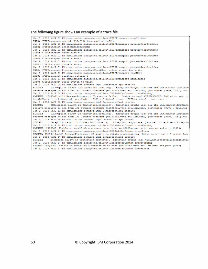
The following figure shows an example of a trace file.
60 © Copyright IBM Corporation 2014
Troubleshooting DataPower Web GUI timeout
By default, Web GUI sessions with DataPower time out after 60 minutes. If your session times
out, or if you want to change the default timeout value, refer to the technote WebGUI session
time out on IBM WebSphere DataPower appliance at http://www-
01.ibm.com/support/docview.wss?uid=swg21256195.
DataPower Configuration Hits and Tips
• You can configure multiple Multi-Protocol Gateways.
• Always click Save after clicking Apply to ensure that configuration changes are saved. Any
change that is not saved might be lost.
• You can configure one or more IMS Callout Front Side Handlers in a single Multi-Protocol
Gateway. For each front-side protocol handlerfront-side handler for IMS Callout support,
you can configure one or more TPIPEs on the same IMS Connect host and port, and same
IMS data store.
• An IMS Callout Front Side Handler cannot be shared by multiple Multi-Protocol Gateways,
but you can move an existing front side handler to a different Multi-Protocol Gateway. To
move an IMS Callout Front Side Handler from one Multi-Protocol Gateway to another:
a. Delete the IMS Callout Front Side Handler from the current Multi-Protocol
Gateway
b. Save the current Multi-Protocol Gateway
c. Add the IMS Callout Front Side Handler to the destination Multi-Protocol Gateway
d. Save the destination Multi-Protocol Gateway.
• By default, IMS Callout Front Side Handlers are enabled when they are created. During
configuration of a Multi-Protocol Gateway, disable the IMS Callout Front Side Handler
until the Multi-Protocol Gateway and the backend service is ready to service requests.
Otherwise, any callout requests sent to the IMS Callout Front Side Handler will get an
error.
Also, if an IMS Callout Front Side Handler is enabled while the Multi-Protocol Gateway is
being configured, each time you apply changes by clicking the Apply button, the Multi-
Protocol Gateway effectively restarts the IMS Callout Front Side Handler and performs
teardown and resume tpipe operations. When the Multi-Protocol Gateway is ready, you
can enable the IMS Callout Front Side Handler to start the retrieval of IMS ICAL requests.
• For failover support, you can configure redundant IMS Callout Front Side Handlers with
the same properties to listen on the same host TPIPE. The first IMS Callout Front Side
Handler on a TPIPE has an active connection with IMS Connect, while the other IMS
Callout Front Side Handlers on the same TPIPE are queued. If the active IMS Callout Front
Side Handler fails, the next one in the queue takes over.
61 © Copyright IBM Corporation 2014

• To display information about how IMS is processing synchronous callout requests, you can
use the IMS command /DISPLAY TMEMBER TPIPE SYNC. The information displayed
includes the number of active synchronous callout messages, the number of synchronous
callout messages waiting for response, the resume tpipe option, the resume tpipe mode,
and the tpipe status. For more information about the command, see /DISPLAY TMEMBER
command in the IMS documentation at
http://www.ibm.com/support/knowledgecenter/SSEPH2_13.1.0/com.ibm.ims13.doc.cr/i
mscmds/ims_displaytmember.htm.
Troubleshooting IMS Callout Front Side Handler
If an error occurs during the processing of an IMS synchronous callout request by DataPower,
follow the steps to diagnose the problem:
1. Enable debug-level logging and examine the log messages for useful information.
• IMS Callout Front Side Handler log: Verify in the log message that IMS Callout Front
Side Handler is able to pass the initial test to validate that both IMS Connect and IMS
are up. The test creates a connection to IMS Connect and sends a /DIS OTMA
command to IMS. In the log, you can correlate a synchronous callout request to its
reply message by the hexadecimal correlator token that uniquely identifies the
transaction.
• Multi-Protocol Gateway log message: Verify that the Multi-Protocol Gateway is able to
flow the message from the IMS Callout Front Side Handler to the backend service and
back.
2. If you do not need to preserve any, you can restart the IMS Callout Front Side Handler by
disabling and re-enabling it. You must click the Apply button after each action. Check the
log messages after restart.
Attention: any in-flight requests or responses are lost when the IMS Callout Front Side
Handler is restarted.
3. If restarting the IMS Callout Front Side Handler does not clear up the problem, you can
restart the domain from the default domain. Again, any in-flight requests or responses will
be lost. If the domain is restarted, the IMS Callout Front Side Handler might not be able to
clean up the resume tpipe connection properly, resulting in an orphaned connection that
must be cleaned up in IMS manually.
4. As a last resort, you can restart DataPower. Again, any in-flight requests or responses will
be lost and the tpipe connection might not clean up properly. To restart DataPower, issue
the DataPower shutdown reload command.
62 © Copyright IBM Corporation 2014
Error Response Considerations
Processing errors can occur in any of the different components in a DataPower for IMS
configuration, such as:
• The IMS Callout Front Side Handler
• The DataPower Multi-Protocol Gateway processing policy, including in the data
transformation stage
• The backend service
The IMS Callout Front Side Handler communicates with DataPower by using the HTTP protocol.
If an error occurs within the IMS Callout Front Side Handler, the following error response is sent
back to the IMS application:
• Return code: X’0100’
• Reason code: X’0100’
• Extended reason code: 2001
• Error message: “REQUEST PROCESSING FAILED, CHECK EXTENDED REASON CODE.“
If an error that occurs after the IMS Callout Front Side Handler sends the request to DataPower,
the following error response is sent to the IMS application:
• Return code: X’0100’
• Reason code: X’0100’
• Extended reason code: 2000-3000 (set as 2000+HTTP error code from DataPower)
• Error message: “REQUEST PROCESSING FAILED, CHECK EXTENDED REASON CODE.“
Troubleshooting ICAL
If an IMS application program receives an error response to an ICAL call, take the following steps
to diagnose the problem:
1. Look up the return codes and reason codes in Table 1 of the ICAL call documentation at
http://www.ibm.com/support/knowledgecenter/SSEPH2_13.1.0/com.ibm.ims13.doc.apr/
ims_icalcalltm.htm.
2. Verify that the ICAL request was sent from IMS Connect. The IMS Connect administrator
can verify in the IMS Connect trace that the data exchange happened. The IMS Connect
administrator can also issue the IMS Connect command VIEWHWS to see:
• The CLIENTID. The client ID of a DataPower IMS Callout Front Side Handler is
generated by IMS Connect and has a prefix ‘DP’, for example: DPxxxxxx.
• The STATUS. The state of the IMS Callout Front Side Handler as recognized by IMS
Connect. See the section ‘Troubleshooting IMS Connect connections’
63 © Copyright IBM Corporation 2014
• The SECOND value. The number of seconds that this connection has remained in
the state shown on the same row under the STATUS output field heading. This
number resets after an ICAL message is delivered.
It is important that a TPIPE is dedicated to only one client, for example, DataPower, SOAP
Gateway, TM Resource Adapter on WebSphere Application Server, and so on. Each client
expects the message in different format. An ICAL message is rejected with return code
(X’100’) and reason code (X’108’) for invalid format if it is received from a tpipe by a client
that does not expect an ICAL call.
3. Verify that DataPower IMS Callout Front Side Handler received the request. This requires
turning on the debug log. Check for IMS Callout Front Side Handler log message at the
time when the ICAL request is sent.
4. Verify that the Multi-Protocol Gateway policy is able to process the data and deliver to the
backend service. This requires turning on the debug log in DataPower. Check for Multi-
Protocol Gateway messages in the log.
5. Verify that DataPower IMS Callout Front Side Handler delivered the response. If the
connection to IMS Connect is not longer usable, the IMS Callout Front Side Handler
attempts to redeliver again on a new connection. If the redelivery attempt fails because of
connection issues, the correlation token is logged and the response is discarded. After
delivering a response, the IMS Callout Front Side Handler waits for an acknowledgement
(ACK) from IMS Connect. If a NACK is received, the correlation token is logged and the
response is discarded.
Troubleshooting IMS Connect connections
When an IMS Callout Front Side Handler is enabled, for each TPIPE that is specified, DataPower
creates a dedicated connection with IMS Connect to listen for ICAL requests. The connection has
a CONN status in IMS Connect while waiting for output from IMS. After IMS Connect sends an
ICAL request, the status of the connection changes to RECV WFCM (Wait-for-Confirm) while IMS
Connect waits for an ACK from the client. After getting the ACK, the status of the connection
changes back to goes back to CONN. The IMS Connect administrator can issue the VIEWHWS
command to see the connection status.
For IMS Version 13 information about the VIEWHWS command and its output, see
http://www.ibm.com/support/knowledgecenter/SSEPH2_13.1.0/com.ibm.ims13.doc.cr/compcm
ds/ims_viewhws.htm.
Note: if you are using IMS Connect Versoion 12 and DataPower is shut down while the IMS
Connect Front Side Handler remains enabled, any existing IMS Connect connections that are in a
CONN state break and must be cleaned up in IMS Connect manually.
IMS Connect Version 13 cleans up broken connections automatically after APARs PM90777 (PTF
UK95578) and PM98701 (PTF UI12241) are applied.
64 © Copyright IBM Corporation 2014
If broken connections are not cleaned up in IMS Connect Version 12 before DataPower is
restarted, the IMS Callout Front Side Handler, which reconnects automatically during restart, will
appear to have twice the number of connections in IMS Connect Version 12. For example, if the
IMS Connect Front Side Handler has 50 active connections with IMS Connect Version 12 when
DataPower shuts down and they are not cleaned up before DataPower is restarted, you will
probably see 100 connections for the Front Side Handler in IMS Connect after restart completes.
Any ICAL requests will still fail, because they would be sent to the original broken connections.
After the broken connections are cleaned up, ICAL processing can resume on the new active
connections.
If IMS Connect Version 12 receives another ICAL request on the broken connection, the request is
rejected and the broken connection is then terminated. The ICAL request is not sent to
DataPower.
To manually clean up a broken connection in IMS Connect administrator can issue a command to
manually destroy a connection. A z/OS MODIFY command is shown in the following example:
F HWS1,DELETE PORT NAME(9999) CLIENT (DP83OEFT)
To avoid broken connections in IMS Connect, before you shut down DataPower, disable the IMS
Callout Front Side Handler and save the configuration.
Error Handling Considerations
You can configure the number of times that an IMS Callout Front Side Handler attempts to
reconnect to IMS after a connection fails before the IMS Callout Front Side Handler goes into a
‘down – pending’ status.
The two parameters are:
1. RetryErrorLimit: The number of times to attempt to resume a connection with a TPIPE
after a connection fails. The default is 5.
2. RetryInterval: The length of time to wait between attempts to resume a connection with a
TPIPE. The default is 3 seconds.
If an error is due to network problem and the IMS Callout Front Side Handler goes in a “down -
pending” state, the Front Side Handler attempts to self-recover.
An internal polling is performed every minute to verify when the network connectivity and/or
IMS availability is reestablished. If the polling is successful, DataPower autonomously changes
the status of the Front Side Handler to ‘up’ and operations are resumed.
In the unlikely event that the IMS Front Side Handler becomes non-operative, DataPower tries to
restart processing automatically.
65 © Copyright IBM Corporation 2014

Configuring access to IMS databasesConfiguring an IMS Database Connection involves configuring components in both the IMS and
DataPower environments.
Configuring IMS Components for access to IMS DB
Access to IMS databases from DataPower requires configuring the following IMS components:
• IMS Connect
• The Open Database Manager (ODBM) of the IMS Common Service Layer (CSL)
OTMA is not used for access to IMS DB.
Configuring IMS Connect for access to IMS DB
An IMS Connect ODACCESS statement is required to configure IMS Connect to support access to
IMS databases from DataPower.
Among other communication attributes, the ODACCESS statement defines the port on which IMS
Connect listens for database access requests from DataPower. The same port number that is
specified on the DRDAPORT keyword of the ODACCESS statement must also be specified in the
Port field when the SQL Data Source is configured in DataPower.
The ODACCESS statement is in addition to the HWS and TCPIP statements that are required for all
types of IMS Connect support. All of the IMS Connect configuration statements are defined in the
HWSCFGxxx member of the IMS.PROCLIB data set.
Configuring ODBM for access to IMS DB
You configure ODBM by specifying an CSLDCxxx member in the IMS.PROCLIB data set.
Among other attributes, the CSLDCxxx member defines an alias name for the IMS DB server
where the database resides. Optionally, this same alias name can be specified in the
dataStoreName field on the Advanced tab when the SQL Data Source is configured.
Configuring DataPower Components for access to IMS DB
Access to the IMS DB database server through DataPower requires configuring the following
components in the DataPower environment:
1. The DataPower Multi-Protocol Gateway
2. A Front Side Protocol handler
3. An SQL Data Source
4. A Multi-Protocol Gateway Processing Policy
5. SQL calls
66 © Copyright IBM Corporation 2014
6. A Matching Rule
7. SQL call enablement in DataPower for IMS
8. A Set Variable Action
9. A Results Action
A backend is not needed to query an IMS Database; DataPower classifies such cases as
“enrichment scenarios”, involving a call to an external source that is not the intended backend.
For our setup we will create a loop feedback using a dynamic backend and XSLT logic.
The configuration steps included in the guide are for a bare minimum configuration, with only the
core request and response processing elements. A complete implementation would have one or
more of the following additional elements:
• Service level monitoring for flow control
• AAA (authentication/authorization)
• Logging elements
• Monitoring elements
67 © Copyright IBM Corporation 2014
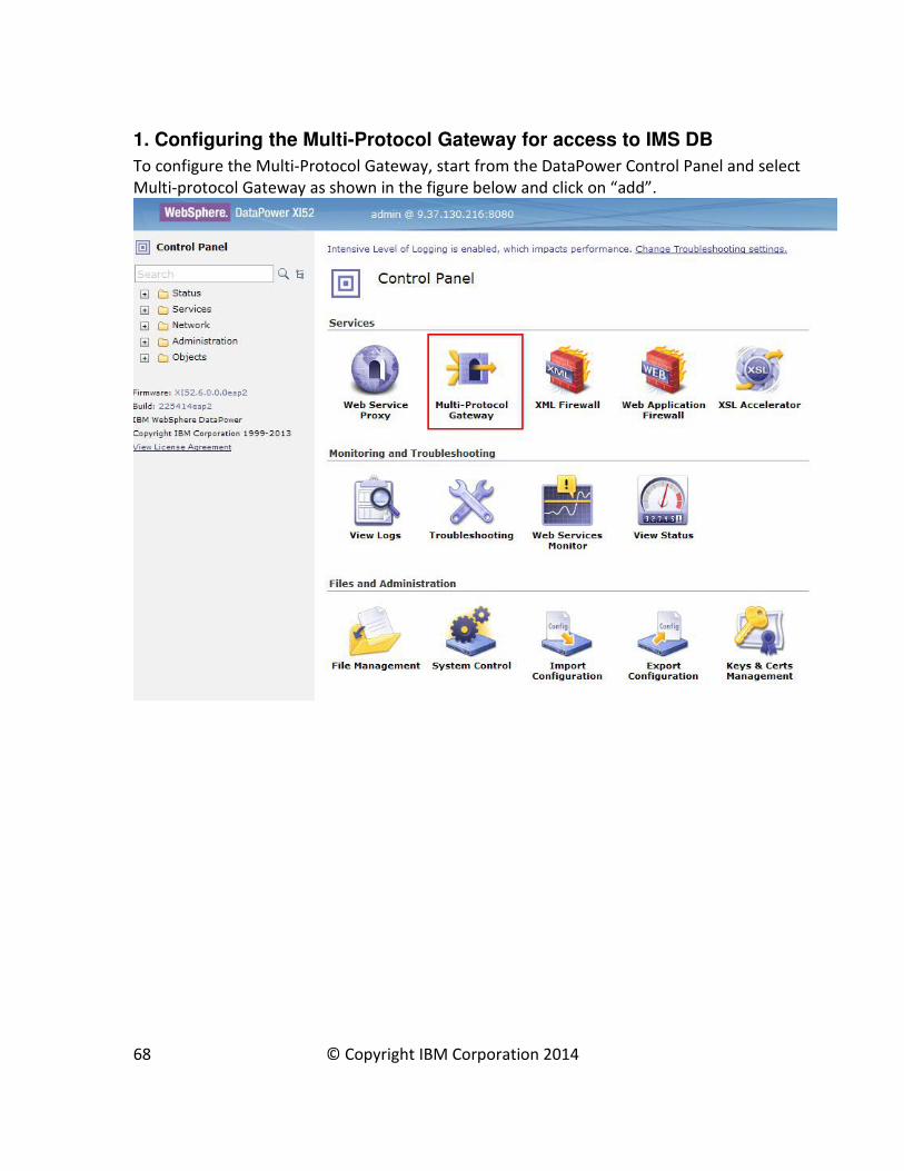
1. Configuring the Multi-Protocol Gateway for access to IMS DB
To configure the Multi-Protocol Gateway, start from the DataPower Control Panel and select
Multi-protocol Gateway as shown in the figure below and click on “add”.
68 © Copyright IBM Corporation 2014

In the “Configure Multi-Protocol Gateway” panel, specify a Multi-Protocol Gateway name.
Toward the bottom of the panel, you must set the request type and response type. Request type
defines the IMS traffic on the front end. Response type defines the web service traffic on the
backend. Specify Non-XML for both request type and response type.
More Advanced settings are available in the Advanced tab.
69 © Copyright IBM Corporation 2014
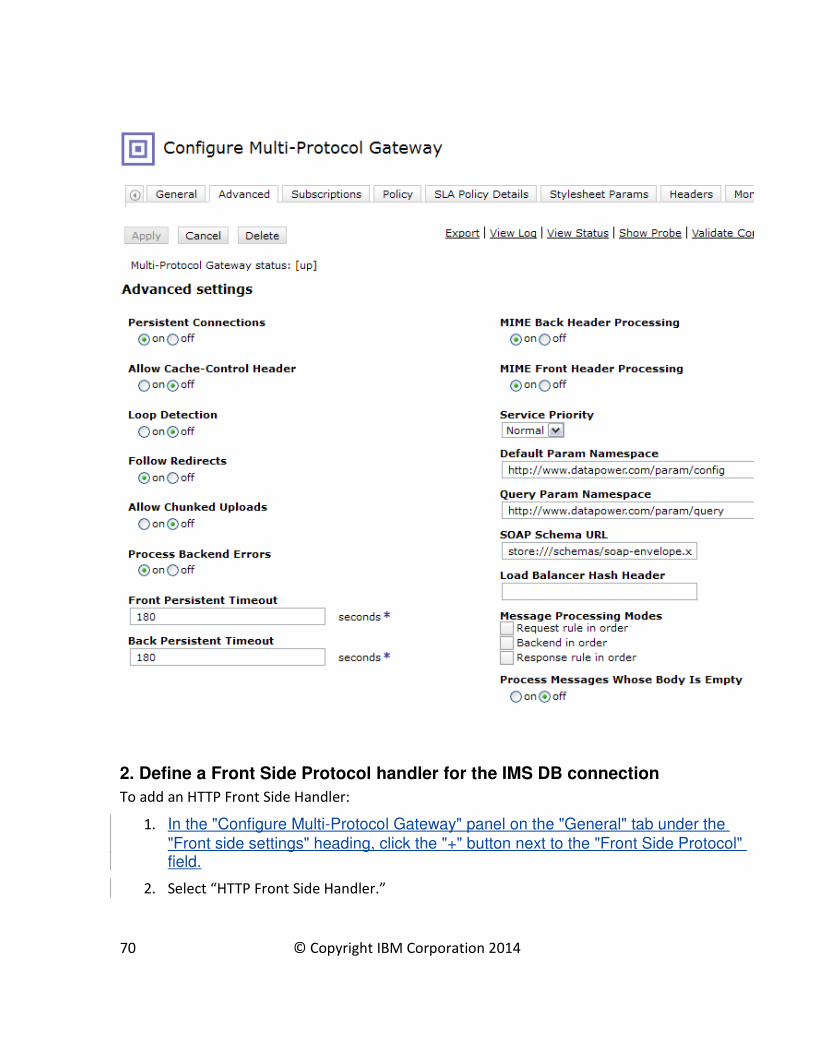
2. Define a Front Side Protocol handler for the IMS DB connection
To add an HTTP Front Side Handler:
1. In the "Configure Multi-Protocol Gateway" panel on the "General" tab under the
"Front side settings" heading, click the "+" button next to the "Front Side Protocol" field.
2. Select “HTTP Front Side Handler.”
70 © Copyright IBM Corporation 2014

3. In the “HTTP Front Side Handler panel, specify the local IP address. A value of 0.0.0.0
defaults the value to the host IP address of the DataPower appliance.
4. Specify a port to listen on.
5. Click Apply on the front side handler panel, then click Apply on the MPGW panel, and
finally click ‘save config’.
71 © Copyright IBM Corporation 2014

3. Configuring an SQL Data Source
An IMS database is defined to DataPower as an SQL data source. For each IMS database that you
will access, you need to configure a separate SQL data source. .
In IMS, a program specification block (PSB) associates an application program with a given
database. When you configure the SQL Data Source in DataPower, to identify the target database
of an application program, you specify the PSB name instead of the database name. The PSB
name is specified in the Data Source ID field. An IMS JDBC driver, which comes preinstalled in the
DataPower appliance, checks the PSB names in the IMS catalog to validate the Data Source ID.
The SQL data source is used by an SQL action in a processing policy. The SQL action retrieves the
data for further processing by the processing policy. Conversely, the processing policy can store
the processed data in the configured database instance.
The SQL Data Source utilizes the IMS Universal JDBC driver to establish a TCP/IP connection to the
IMS system. This allows users to issue dynamic SQL calls to the underlying database, and returns
the result set in tabular format.
To define an SQL Data Source, use the navigation panel on the left of the main DataPower
Control panel:
72 © Copyright IBM Corporation 2014
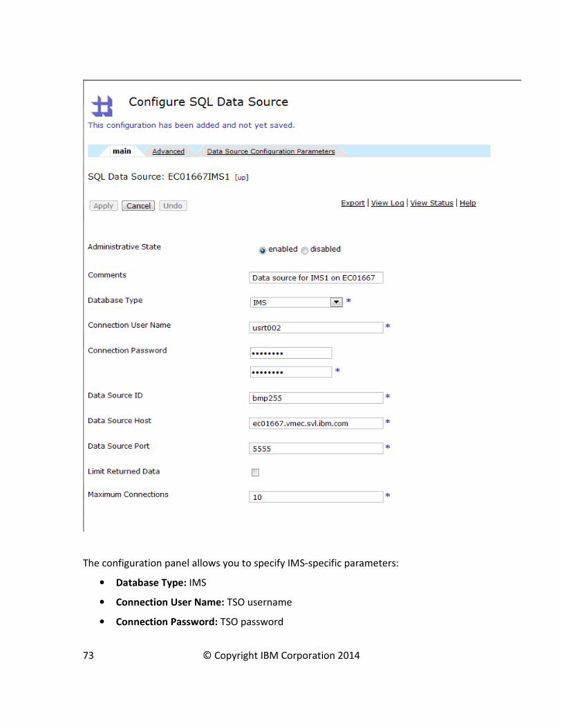
The configuration panel allows you to specify IMS-specific parameters:
• Database Type: IMS
• Connection User Name: TSO username
• Connection Password: TSO password
73 © Copyright IBM Corporation 2014

• Data Source ID: The name of the program specification block (PSB) that identifies the
database to connect to
• Data Source Host: The IP address of the host on which the IMS system resides
• Data Source Port: The port on which IMS Connect receives database access requests. This
port is defined to IMS Connect on the DRDAPORT keyword of the ODACCESS configuration
statement.
Accept the defaults for the other parameters on this panel.
You can specify additional parameters under the “Data Source Configuration Parameters” tab.
Some commonly used name-value pairs are:
• datastoreName: The name of your IMS system. This parameter is optional. When the
datastoreName is omitted, IMS Connect searches for the appropriate IMS system among
the active IMS systems that it is currently connected to. Specifying the datastoreName can
result in a minor performance improvement. When specified, the datastoreName value
must match an IMS alias name that is defined on the NAME keyword of the ALIAS
statement in the CSLDCxxx member of the IMS.PROCLIB data set.
• traceFile: The full path and file name to which DataPower will write log messages. This is
used mainly for debugging.
• traceLevel: The level of logging for traceFile. The value -1 indicates that all messages are
logged. This is also used for debugging in conjunction with traceFile.
When you’re done configuring the SQL data source, click Apply.
On the Multi-Protocol Gateway panel, click Apply again.
Finally, click “save config”.
74 © Copyright IBM Corporation 2014

4. Defining a Processing Policy for IMS DB access
A processing policy is defined as a part of the configuration of a Multi-Protocol Gateway. A
processing policy defines the actions DataPower takes against data passed through to the
endpoint service. It consists of one or more rules.
A rule is depicted as a line in the policy definition panel, and consists of actions. Each rule must
consist of:
• A Match Action, which processes an incoming request based on its target URL
• A Transform Action
• Optionally, a loop feedback for testing purposes
• A Results Action
Each rule can be configured to flow from client to server, vice-versa, or in both directions.
4a. Defining a policy
To define a new policy:
1. Under the General tab on the Configure Multi-Protocol Gateway panel, click on the “+”
button
2. Specify the name for the policy
3. Click Apply
After defining the new policy, define a rule for the processing policy.
75 © Copyright IBM Corporation 2014
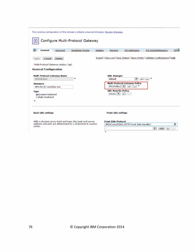
76 © Copyright IBM Corporation 2014

4b. Defining a New Rule
In the policy definition panel, a rule is depicted as a line between a server and a client. Matching,
processing, and results actions are added to the rule by dragging icons onto the line.
To define a new rule:
1. Enter a name in the Rule Name field
2. Specify the rule direction
3. Click the New Rule button
4. Add actions to the rule by dragging action icons onto the rule line
4c. Defining a Match Action
A Match Action contains one or more Matching Rules. A matching rule defines the criteria to
determine whether incoming traffic is processed by its processing rule. For example, you might
77 © Copyright IBM Corporation 2014

specify a matching action that applies the rule to any incoming message that specifies all or part
of the URL address of the IMS DB server.
To define a matching rule:
1. Drag a matching icon, , onto the Rule line
2. Double click on the Matching rule icon (equals sign) and then on the edit (“…”).The
Configure Matching Rule panel displays:
3. Use the “Matching Rule” tab to configure this matching rule. An asterisk indicates a
wildcard. The rule shown in the following figure will process all requests with target URL
http://<hostname>:<port>/imsdb/<anything>.
78 © Copyright IBM Corporation 2014

4d. Configure a Transform Action (XSL Stylesheet-driven action)
Before you add a Transform Action for accessing IMS databases, you should have an XSL
stylesheet available and ready for upload into the Transform Action. For more information about
coding an XSL stylesheet, see Enabling SQL calls in DataPower for IMS.
The stylesheet is used to:
• Direct the web services input message, also referred as payload, to the proper IMS system
• Specify the IMS program specification block (PSB) to use
• The query to perform
• The SQL Data Source (IMS) to use
To configure a Transform Action:
1. Drag the Transform Action icon, , onto the rule line, right after the
matching action.
2. Double-click the Transform Action icon on the rule line to open the configure the
Transform Action.
3. Upload the stylesheet (.xsl file) by clicking the Upload… button.
79 © Copyright IBM Corporation 2014
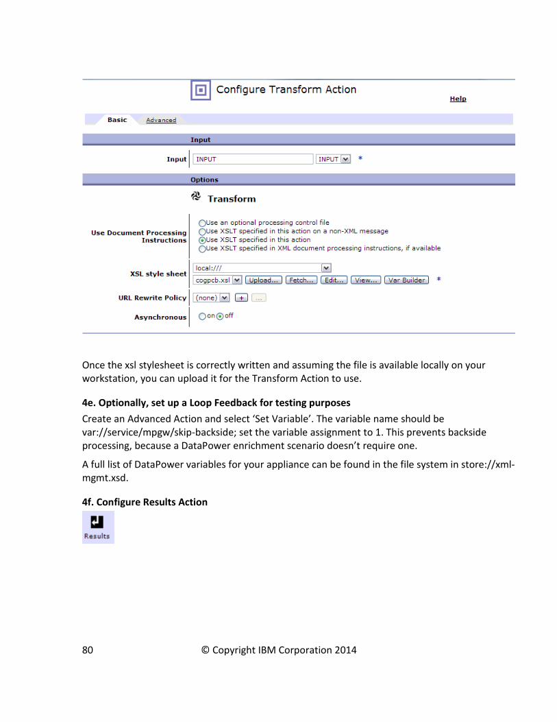
Once the xsl stylesheet is correctly written and assuming the file is available locally on your
workstation, you can upload it for the Transform Action to use.
4e. Optionally, set up a Loop Feedback for testing purposes
Create an Advanced Action and select ‘Set Variable’. The variable name should be
var://service/mpgw/skip-backside; set the variable assignment to 1. This prevents backside
processing, because a DataPower enrichment scenario doesn’t require one.
A full list of DataPower variables for your appliance can be found in the file system in store://xml-
mgmt.xsd.
4f. Configure Results Action
80 © Copyright IBM Corporation 2014
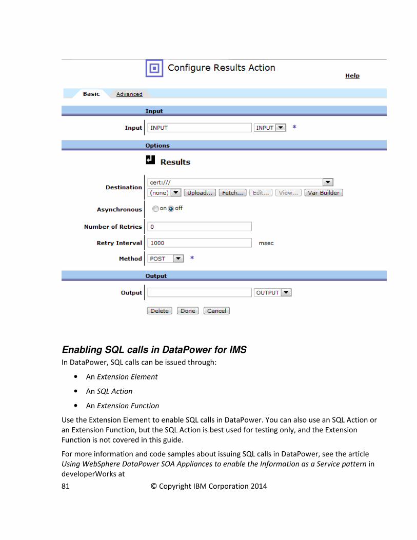
Enabling SQL calls in DataPower for IMS
In DataPower, SQL calls can be issued through:
• An Extension Element
• An SQL Action
• An Extension Function
Use the Extension Element to enable SQL calls in DataPower. You can also use an SQL Action or
an Extension Function, but the SQL Action is best used for testing only, and the Extension
Function is not covered in this guide.
For more information and code samples about issuing SQL calls in DataPower, see the article
Using WebSphere DataPower SOA Appliances to enable the Information as a Service pattern in
developerWorks at
81 © Copyright IBM Corporation 2014
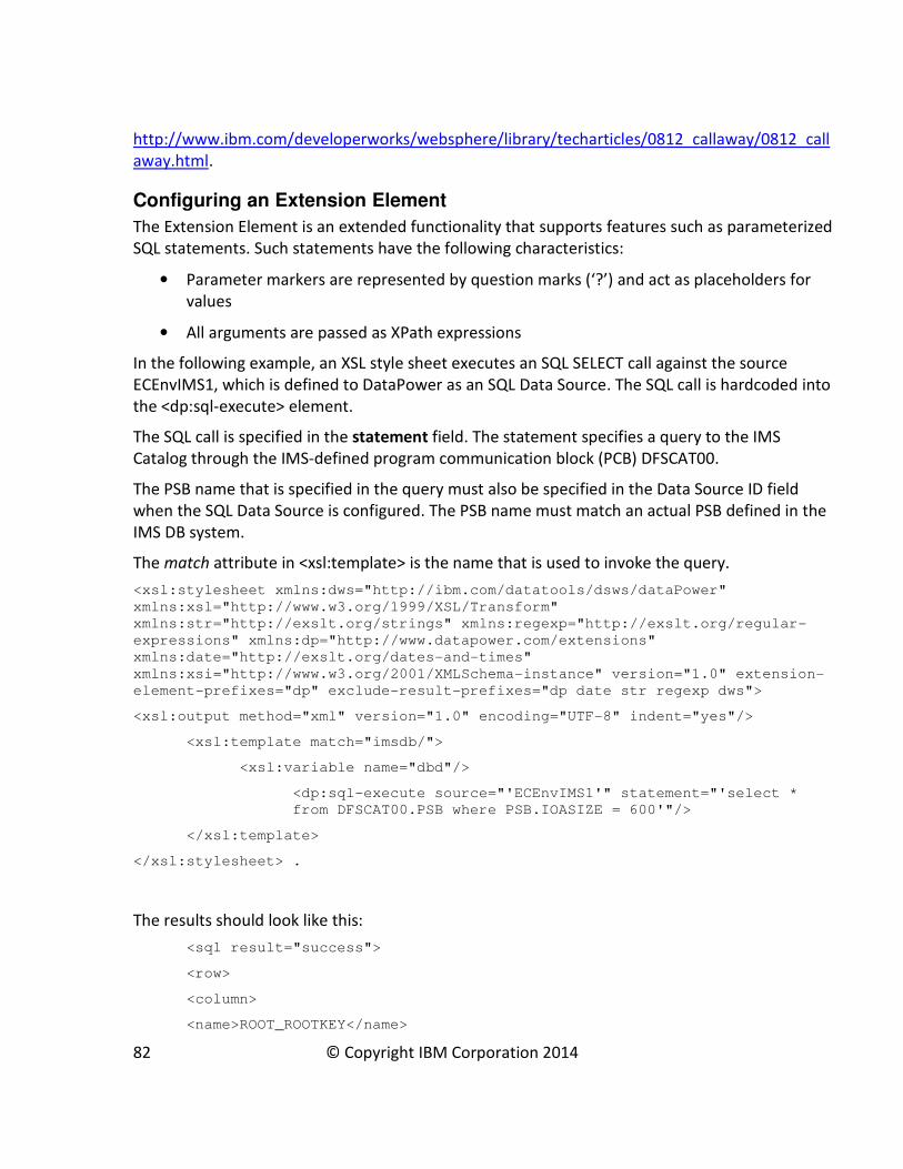
http://www.ibm.com/developerworks/websphere/library/techarticles/0812_callaway/0812_call
away.html.
Configuring an Extension Element
The Extension Element is an extended functionality that supports features such as parameterized
SQL statements. Such statements have the following characteristics:
• Parameter markers are represented by question marks (‘?’) and act as placeholders for
values
• All arguments are passed as XPath expressions
In the following example, an XSL style sheet executes an SQL SELECT call against the source
ECEnvIMS1, which is defined to DataPower as an SQL Data Source. The SQL call is hardcoded into
the <dp:sql-execute> element.
The SQL call is specified in the statement field. The statement specifies a query to the IMS
Catalog through the IMS-defined program communication block (PCB) DFSCAT00.
The PSB name that is specified in the query must also be specified in the Data Source ID field
when the SQL Data Source is configured. The PSB name must match an actual PSB defined in the
IMS DB system.
The match attribute in <xsl:template> is the name that is used to invoke the query.
<xsl:stylesheet xmlns:dws="http://ibm.com/datatools/dsws/dataPower"
xmlns:xsl="http://www.w3.org/1999/XSL/Transform"
xmlns:str="http://exslt.org/strings" xmlns:regexp="http://exslt.org/regular-
expressions" xmlns:dp="http://www.datapower.com/extensions"
xmlns:date="http://exslt.org/dates-and-times"
xmlns:xsi="http://www.w3.org/2001/XMLSchema-instance" version="1.0" extension-
element-prefixes="dp" exclude-result-prefixes="dp date str regexp dws">
<xsl:output method="xml" version="1.0" encoding="UTF-8" indent="yes"/>
<xsl:template match="imsdb/">
<xsl:variable name="dbd"/>
<dp:sql-execute source="'ECEnvIMS1'" statement="'select *
from DFSCAT00.PSB where PSB.IOASIZE = 600'"/>
</xsl:template>
</xsl:stylesheet> .
The results should look like this:
<sql result="success">
<row>
<column>
<name>ROOT_ROOTKEY</name>
82 © Copyright IBM Corporation 2014
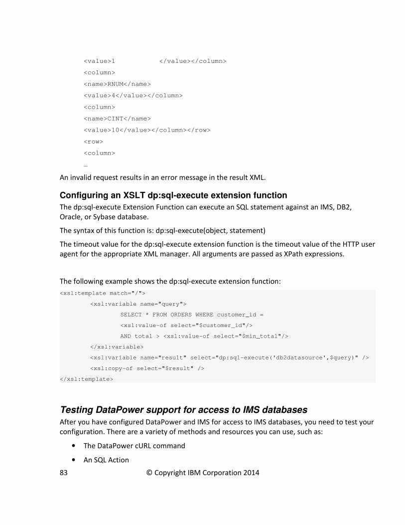
<value>1 </value></column>
<column>
<name>RNUM</name>
<value>4</value></column>
<column>
<name>CINT</name>
<value>10</value></column></row>
<row>
<column>
…
An invalid request results in an error message in the result XML.
Configuring an XSLT dp:sql-execute extension function
The dp:sql-execute Extension Function can execute an SQL statement against an IMS, DB2,
Oracle, or Sybase database.
The syntax of this function is: dp:sql-execute(object, statement)
The timeout value for the dp:sql-execute extension function is the timeout value of the HTTP user
agent for the appropriate XML manager. All arguments are passed as XPath expressions.
The following example shows the dp:sql-execute extension function:
<xsl:template match="/">
<xsl:variable name="query">
SELECT * FROM ORDERS WHERE customer_id =
<xsl:value-of select="$customer_id"/>
AND total > <xsl:value-of select="$min_total"/>
</xsl:variable>
<xsl:variable name="result" select="dp:sql-execute('db2datasource',$query)" />
<xsl:copy-of select="$result" />
</xsl:template>
Testing DataPower support for access to IMS databases
After you have configured DataPower and IMS for access to IMS databases, you need to test your
configuration. There are a variety of methods and resources you can use, such as:
• The DataPower cURL command
• An SQL Action
83 © Copyright IBM Corporation 2014
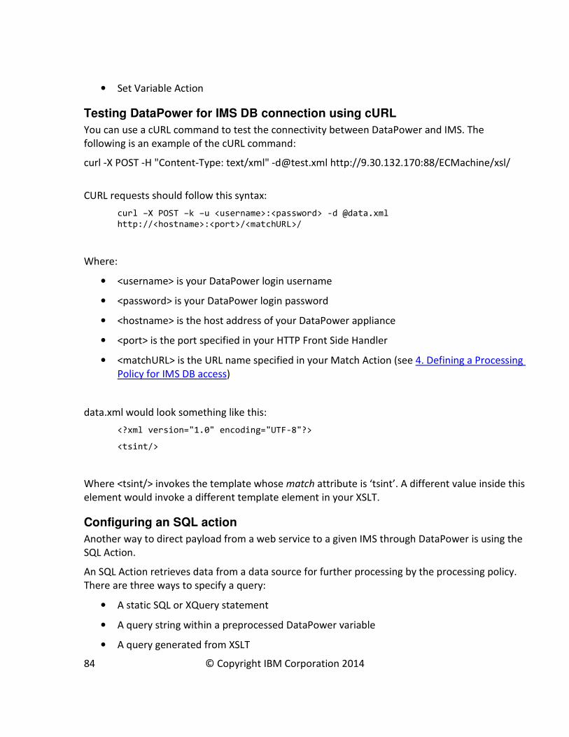
• Set Variable Action
Testing DataPower for IMS DB connection using cURL
You can use a cURL command to test the connectivity between DataPower and IMS. The
following is an example of the cURL command:
curl -X POST -H "Content-Type: text/xml" [email protected] http://9.30.132.170:88/ECMachine/xsl/
CURL requests should follow this syntax:
curl –X POST –k –u <username>:<password> -d @data.xml
http://<hostname>:<port>/<matchURL>/
Where:
• <username> is your DataPower login username
• <password> is your DataPower login password
• <hostname> is the host address of your DataPower appliance
• <port> is the port specified in your HTTP Front Side Handler
• <matchURL> is the URL name specified in your Match Action (see 4. Defining a Processing
Policy for IMS DB access)
data.xml would look something like this:
<?xml version="1.0" encoding="UTF-8"?>
<tsint/>
Where <tsint/> invokes the template whose match attribute is ‘tsint’. A different value inside this
element would invoke a different template element in your XSLT.
Configuring an SQL action
Another way to direct payload from a web service to a given IMS through DataPower is using the
SQL Action.
An SQL Action retrieves data from a data source for further processing by the processing policy.
There are three ways to specify a query:
• A static SQL or XQuery statement
• A query string within a preprocessed DataPower variable
• A query generated from XSLT
84 © Copyright IBM Corporation 2014

An SQL Action is not a particularly flexible way to use SQL in DataPower, and the best practice to
use the extension element that is described in Configuring an XSLT dp:sql-execute extension
element.
The SQL Action can be useful for testing, because it is easy to configure and use. It is basically a
pointer to a pre-defined SQL Data Source (IMS) with a specific query to perform.
After defining a processing policy, as described in 4. Defining a Processing Policy for IMS DB
access, you can configure an SQL Action in the Create Rule panel by using the following steps:
1. Drag the Advanced Action icon, , onto the rule line.
2. Double click the Advanced Action icon to open the Configure Action panel.
3. Select SQL from the list of operations.
4. Click Next. The Configure SQL Action panel displays.
85 © Copyright IBM Corporation 2014

86 © Copyright IBM Corporation 2014

5. In the Configure SQL Action panel, specify:
• INPUT in the Input field
• The IMS PSB name in the SQL Data Source field
• Static in the SQL Input Method field
• The SQL call in the SQL Text field
87 © Copyright IBM Corporation 2014

After the SQL Action is added to the rule, the rule should look similar to the rule shown in the
following figure:
To drive the SQL Action, you can use cURL command that has the keyword specified in the Match
Action for the IMS1Policy2_rule_3_SQL_Action. For example:
curl -X POST -H "Content-Type: text/xml" [email protected] http://192.0.2.0:88/ECMachine/sqlact/
Configuring Set Variable Action
For connection testing purposes, defining a Set Variable Action with the skip-backside variable
can be useful.
If your configuration includes a back-end server, such as Web Application Server, using the skip-
backside variable might useful. The skip-backside variable essentially converts a processing rule
to provide a loopback action: instead of sending transformed request data to a backend server,
the data is echoed back to the client immediately.
This can be a convenient way to set up tests that are not dependent on a backend server.
The following figure shows how a skip-backside Variable Action can be used within DataPower.
88 © Copyright IBM Corporation 2014

The SQL request (IMS DB call) is a SideCall, which is usually used to enrich the data in requests
and responses. The SideCall method is often used, and is sometimes referred as an "enrichment"
scenario.
Regardless, the Variable Action Skip-Backside is not required, and is not likely to be useful outside
of a test environment.
89 © Copyright IBM Corporation 2014

Configuring access to IMS transactionsTo configure DataPower and IMS to support access to the IMS TM server, you need to configure
components in both the IMS and DataPower environments:
In the IMS environment, you need to configure:
• OTMA
• IMS Connect
In the DataPower environment, you need to configure:
• Multi-Protocol Gateway
• IMS Connect access for provider
Configuring IMS components for access to IMS TM from DataPower
To support access to IMS TM from DataPower, the configuration steps in IMS are generally the
same as they are for configuring access to IMS TM from any other IMS Connect client:
• OTMA must be enabled in the IMS system
• IMS Connect must be configured for IMS TM access with a DATASTORE configuration
statement
Enabling OTMA
If OTMA is not already enabled in the IMS system, you can enable it by specifying the z/OS® cross-
system coupling facility (XCF) group name and IMS OTMA member name during IMS system
definition.
OTMA is installed with IMS TM. The IMS INSTALL/IVP Dialog is not used to install OTMA.
To start OTMA, you can use the OTMA=Y startup parameter in the IMS procedure during IMS
system definition or, after an IMS restart, issue the type-1 command /START OTMA.
Configuring IMS Connect for access to IMS TM from DataPower
In addition to HWS and TCPIP configuration statements, you must define a DATASTORE
configuration statement when configuring IMS Connect to support access to IMS TM from
DataPower. A DATASTORE statement defines a connection between IMS Connect and the IMS TM
system on which the transactions will run.
IMS Connect configuration statements are defined in the IMS Connect HWSCFGxx member of the
IMS.PROCLIB data set to support access to IMS TM through DataPower.
90 © Copyright IBM Corporation 2014
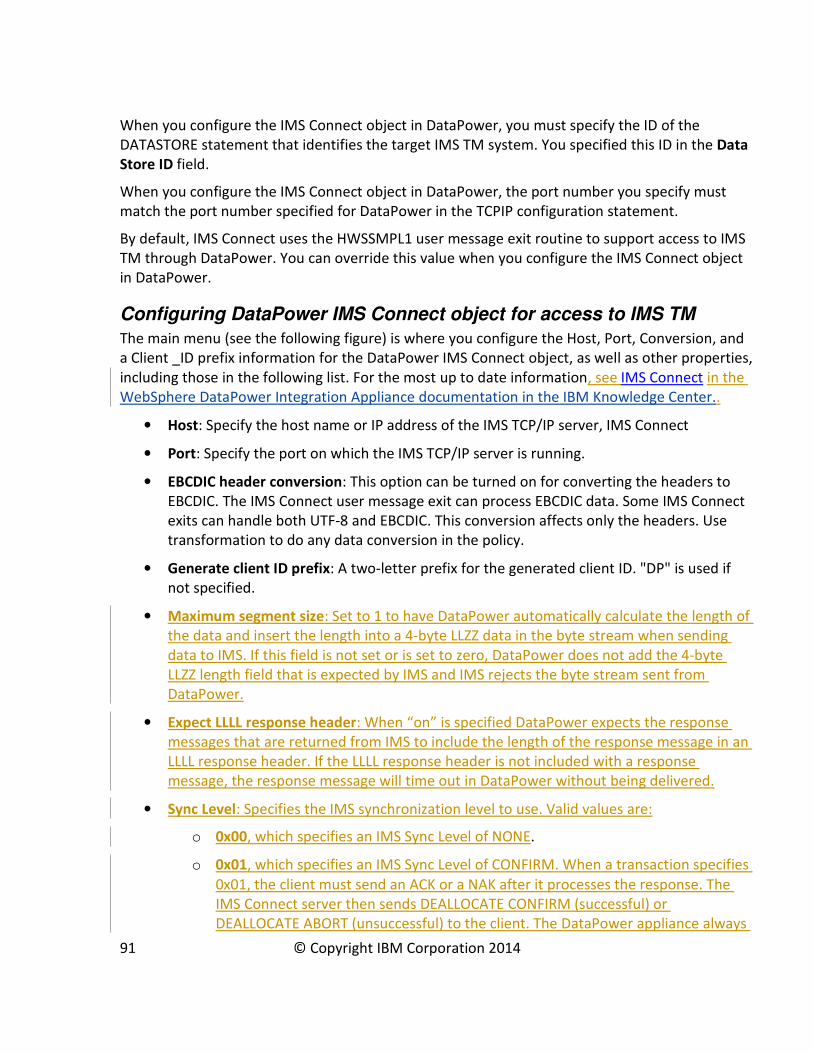
When you configure the IMS Connect object in DataPower, you must specify the ID of the
DATASTORE statement that identifies the target IMS TM system. You specified this ID in the Data
Store ID field.
When you configure the IMS Connect object in DataPower, the port number you specify must
match the port number specified for DataPower in the TCPIP configuration statement.
By default, IMS Connect uses the HWSSMPL1 user message exit routine to support access to IMS
TM through DataPower. You can override this value when you configure the IMS Connect object
in DataPower.
Configuring DataPower IMS Connect object for access to IMS TM
The main menu (see the following figure) is where you configure the Host, Port, Conversion, and
a Client _ID prefix information for the DataPower IMS Connect object, as well as other properties,
including those in the following list. For the most up to date information, see IMS Connect in the
WebSphere DataPower Integration Appliance documentation in the IBM Knowledge Center..
• Host: Specify the host name or IP address of the IMS TCP/IP server, IMS Connect
• Port: Specify the port on which the IMS TCP/IP server is running.
• EBCDIC header conversion: This option can be turned on for converting the headers to
EBCDIC. The IMS Connect user message exit can process EBCDIC data. Some IMS Connect
exits can handle both UTF-8 and EBCDIC. This conversion affects only the headers. Use
transformation to do any data conversion in the policy.
• Generate client ID prefix: A two-letter prefix for the generated client ID. "DP" is used if
not specified.
• Maximum segment size: Set to 1 to have DataPower automatically calculate the length of
the data and insert the length into a 4-byte LLZZ data in the byte stream when sending
data to IMS. If this field is not set or is set to zero, DataPower does not add the 4-byte
LLZZ length field that is expected by IMS and IMS rejects the byte stream sent from
DataPower.
• Expect LLLL response header: When “on” is specified DataPower expects the response
messages that are returned from IMS to include the length of the response message in an
LLLL response header. If the LLLL response header is not included with a response
message, the response message will time out in DataPower without being delivered.
• Sync Level: Specifies the IMS synchronization level to use. Valid values are:
o 0x00, which specifies an IMS Sync Level of NONE.
o 0x01, which specifies an IMS Sync Level of CONFIRM. When a transaction specifies
0x01, the client must send an ACK or a NAK after it processes the response. The
IMS Connect server then sends DEALLOCATE CONFIRM (successful) or
DEALLOCATE ABORT (unsuccessful) to the client. The DataPower appliance always
91 © Copyright IBM Corporation 2014

sends an ACK on receiving the response and then checks for the DEALLOCATE
CONFIRM.
Additional parameters that need to be customized are:
• Exit Program
The IMS Connect user message exit routine to use for all the IMS connections.
• Client ID
A string of 1 to 8 uppercase alphanumeric (A through Z, 0 to 9) or special (@, #, $)
characters, left justified, and padded with blanks. It specifies the name of the client ID
that is used by IMS Connect. If this string is not supplied from the client, then the IMS
Connect user message exit routine generates it.
• Transaction code
The code of the transaction to invoke in IMS.
92 © Copyright IBM Corporation 2014

• Data store
It specifies the Datastore name (IMS destination ID).
• Logical terminal name
The LTERM override value to be used by OTMA.
• RACF ID
The plain text string sent to the server for identifying the client.
• RACF Password
The host security password used to login to the IMS TCP/IP server, IMS Connect.
• RACF Group
The group the Host security ID belongs to.
• Encoding scheme
Select the Unicode encoding schema. Leave as (none) to be set dynamically in the IMS
header.
• IRM Timer
Specifies the amount of time that IMS Connect waits for IMS to return response data. An
example value of 21 would set an IRM Timer value of 0.21 sec. For IMS Version 13
information about specifying timeout values, see IMS Connect timeout specifications in
the IMS documentation at
http://www.ibm.com/support/knowledgecenter/SSEPH2_13.1.0/com.ibm.ims13.doc.ccg/i
ms_ct_timeout_specs.htm.
After applying the changes, the confirmation panel appears.
On the View Status Panel, the Object Status of the recently added IMS Connect Object is
displayed.
Status:
• Invalid: Invalid Configuration
• Saved: Persisted Configuration
• New: New Configuration
• Modified: Modified Configuration
• Deleted: Deleted Configuration
• External: External Configuration
System log for the DataPower IMS Connect object
The system log for the IMS Connect object is where DataPower displays the activities associated
with a connector. In this example, `Event Code 0x00360013 - Configured', indicates a valid
configuration. The object is configured but not active at this time
93 © Copyright IBM Corporation 2014

94 © Copyright IBM Corporation 2014

Monitoring and Analyzing Performance of a DataPower for IMSSolution
Monitoring the health and capacity of the DataPower and IMS components in a DataPower for
IMS solution is important to ensure that all of the components are functioning correctly and
efficiently.
Monitoring not only notifies administrators of exceptions, it also provides trending analysis for
managing the various components. Performance measurements can help assess their capacity
utilization over time, thus enabling the organization to maximize its return-on-investment and
properly manage increases in network volumes, exploit the solution potential capacity and help
reaching the desired Service Level Agreements.
The following sections in this topic describe the basic methodology and the key pieces of data
needed when performing Monitoring and Performance analysis of the DataPower for IMS
solution. This basic methodology applies to all types of DataPower support for IMS; however, the
DataPower support for IMS synchronous callout requests is used to provide the examples in this
topic.
For the DataPower section the information reported is based on the Firmware Revision 6.0.0.0.
Status indicators can change between DataPower firmware revisions, so check the latest
firmware documentation for any additions or modifications to monitoring components.
IMS Monitoring and Performance Analysis
Comparing current performance against a performance baseline is often the best method for
evaluating performance, so it is important to establish a performance baseline for the IMS
dependent regions, IMS Connect, and applications that use synchronous callout and ICAL calls.
Any configuration changes to improve performance of either IMS or DataPower can then have a
meaningful context to assess the benefit demonstrated by the new measurements.
It should be noted that even with the same operating system, storage, and processor
configurations, variations in workload and network conditions can cause significant differences in
performance; therefore workload and network conditions must also be taken into account when
comparing current performance against a baseline.
While the performance and monitoring activity is a relatively complex activity, this chapter
focuses on only the steps necessary to collect data and evaluate DataPower support for IMS and
IMS synchronous callout processing. This information is more of a general guide than a
comprehensive reference.
Although z/OS and IMS provide helpful no-cost monitoring tools, such as the IMS Monitor, your
installation might need additional tools to collect all of the data required for a complete IMS
performance evaluation. This guide does not document all available tools; however, the following
list includes some of the tools that IBM provides for performance analysis.
95 © Copyright IBM Corporation 2014
• IBM® IMS™ Performance Analyzer for z/OS® (IMS PA): a performance analysis and tuning
aid for IMS Database (IMS DB) and Transaction Manager (IMS TM) systems. An example of
how to use IMS PA for synchronous callout performance measurements is included in this
guide.
• IBM® IMS™ Connect Extensions for z/OS is an excellent tool for monitoring and recording
IMS Connect activity. Detailed journaling and reporting provides information to help you
analyze performance, throughput, resource availability, and security related to IMS
Connect traffic. This tool can be useful for understanding possible throughput bottlenecks
and for measuring transaction transit times, which is the amount of time it takes IMS
Connect to get a response to messages sent to either DataPower or OTMA in IMS.
• IBM® IMS™ Problem Investigator for z/OS (IMS PI) can be used in a performance and
monitoring context to obtain a single, logical, end-to-end picture of a transaction's life
cycle. Even without an expert understanding of log data structures and the relationships
between log records, the IMS PI interactive ISPF panels enable a drill-down analysis of any
performance issue that is highlighted in IMS PA reports.
For a more comprehensive overview of IMS performance monitoring and tuning information
refer to the IBM Redbook: IMS Performance and Tuning Guide (IBM Form Number SG24-
7324-00 or ISBN 0738494615)
Collecting processing and performance data in IMS
You can collect data about the IMS processing of messages sent to and received from a
DataPower appliance by issuing commands in IMS. These commands return key information for
determining the level of performance in IMS.
In particular, the following three commands are useful for collecting data about performance.
• /TRACE SET (ON/OFF) MONITOR ALL
• /CHECKPOINT STATISTICS
• /SWITCH OLDS
Use caution when issuing these commands in a production environment, because the processing
of some of these commands can significantly impact the performance of your system and the
amount of logging performed by IMS on the OLDS data set.
/TRACE SET (ON/OFF) MONITOR ALL
Use this command to activate the IMS™ Monitor. This feature collects data while the online IMS
subsystem is running and gathers information for all dispatch events. This information is then
placed in the form of IMS Monitor records (specifically log records with the ID of x’78’ and x’79’)
in a sequential data set. Use the IMSMON DD statement in the IMS control region JCL to specify
the IMS Monitor data set.
Make sure that your monitor data sets have been cleared from any previous run.
96 © Copyright IBM Corporation 2014

Monitor log records can be later made available as input to your performance analysis tool, such
as IMS PA. IMS PA can generate reports, including a resource usage report for synchronous
callout activity analysis and for the average response time for ICAL calls.
The IMS master terminal operator (MTO) can start and stop the IMS Monitor to obtain snapshots
of the system at any time. However, be mindful that the IMS Monitor adds to system overhead
and generates a considerable amount of data.
/CHECKPOINT STATISTICS
Use this command to collect performance related statistics and to write dedicated log records to
the system log data set (for example, the OLDS).
Statistics records provide a useful guide to the performance of IMS resources, including the IMS
message queue, various buffer pools, transaction control blocks (TCBs), Internal Resource Lock
Manager (IRLM), and many others. Entering this command during a workload analysis is a key
part of the performance evaluation process and an essential piece of information when the IMS
PA is used.
The beginning of this particular type of checkpoint is delimited in the OLDS by a record with the
ID of x’4001’ (Checkpoint Begin) and x’45FF’ (End of Statistics). The records containing the actual
statistics and performance information use a record ID x’45xx’.
Note: when high volumes of workload are processed by IMS, this command can take a
considerable amount of time to complete.
/SWITCH OLDS
Whichever performance analysis tools you use to process IMS log data and IMS Monitor data, it is
advisable to have the beginning and end of the statistics/performance records isolated in a
specific IMS OLDS dataset. You can use two /SWITCH OLDS commands to control in which system
log data set the data is recorded. Use the message DFS3257I to identify the log DD used in the
IMS start up procedure that indentifies the OLDS datasets names.
DFS3257I ONLINE LOG NOW SWITCHED - FROM DFSOLP01 TO DFSOLP02
DFS058I 17:12:53 SWITCH COMMAND COMPLETED
In a typical performance analysis data collection scenario, you can issue the following sequence
of commands to gather the necessary information:
1. /TRACE SET ON MONITOR ALL
2. /SWITCH OLDS
3. /CHE STATISTICS
4. Assuming that your workload is being executed wait for some time period, 5
minutes, for example
5. /CHE STATISTICS
97 © Copyright IBM Corporation 2014
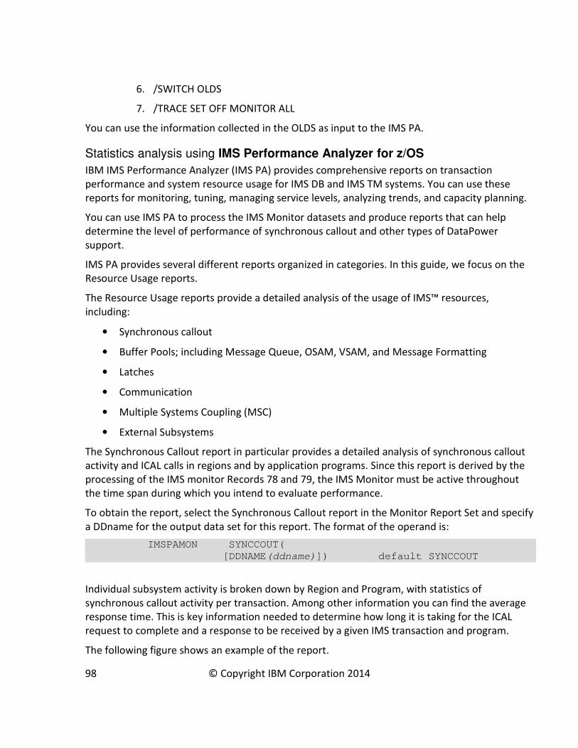
6. /SWITCH OLDS
7. /TRACE SET OFF MONITOR ALL
You can use the information collected in the OLDS as input to the IMS PA.
Statistics analysis using IMS Performance Analyzer for z/OS
IBM IMS Performance Analyzer (IMS PA) provides comprehensive reports on transaction
performance and system resource usage for IMS DB and IMS TM systems. You can use these
reports for monitoring, tuning, managing service levels, analyzing trends, and capacity planning.
You can use IMS PA to process the IMS Monitor datasets and produce reports that can help
determine the level of performance of synchronous callout and other types of DataPower
support.
IMS PA provides several different reports organized in categories. In this guide, we focus on the
Resource Usage reports.
The Resource Usage reports provide a detailed analysis of the usage of IMS™ resources,
including:
• Synchronous callout
• Buffer Pools; including Message Queue, OSAM, VSAM, and Message Formatting
• Latches
• Communication
• Multiple Systems Coupling (MSC)
• External Subsystems
The Synchronous Callout report in particular provides a detailed analysis of synchronous callout
activity and ICAL calls in regions and by application programs. Since this report is derived by the
processing of the IMS monitor Records 78 and 79, the IMS Monitor must be active throughout
the time span during which you intend to evaluate performance.
To obtain the report, select the Synchronous Callout report in the Monitor Report Set and specify
a DDname for the output data set for this report. The format of the operand is:
IMSPAMON SYNCCOUT(
[DDNAME(ddname)]) default SYNCCOUT
Individual subsystem activity is broken down by Region and Program, with statistics of
synchronous callout activity per transaction. Among other information you can find the average
response time. This is key information needed to determine how long it is taking for the ICAL
request to complete and a response to be received by a given IMS transaction and program.
The following figure shows an example of the report.
98 © Copyright IBM Corporation 2014

The report contains the following fields and information:
Rgn No.
The Region number.
PSBname
The PSB (program) name.
Trancode
The transaction code.
Sync Call-Outs
Count
The number of synchronous callout requests.
Avg Elapse Sc.Mil.Mic
The average elapsed time of a synchronous callout request, in microseconds.
Std Dev
The standard deviation of the elapsed time of the synchronous callout requests.
Max Elapse Sc.Mil.Mic
The maximum elapsed time of a synchronous callout request, in microseconds.
Max RC
The maximum return code from a synchronous callout request.
Transaction
Count
The number of transactions that issued the synchronous callout requests.
Avg Elapse Sc.Mil.Mic
The average elapsed time of the transactions, in microseconds.
99 © Copyright IBM Corporation 2014
Calls/Tran
The average number of synchronous callout requests made by a transaction.
Pct Elaps
The percentage of time that transactions spent processing synchronous callout requests.
For more information about how to analyze a Synchronous Callout report, see Synchronous
Callout report in the IMS PA documentation at
http://www.ibm.com/support/knowledgecenter/SSAVHQ/welcome?lang=en.
Key Data and fields to create a performance baseline report
The key data points can vary by user based on how and where an ICAL call is used. For example, if
an application issued one ICAL call from an IMS transaction, some key data might include:
• From IMS Performance Analyzer Summary Report
o Transaction count (Tran Count) for the transaction of interest – this can be used
with the interval duration to determine the transaction rate of the given
transaction
o Average Input Queue Time – If this time is high than that means your transaction is
waiting to be scheduled into a dependent region. If there is a need to reduce
transaction elapsed time then more IMS Dependent Regions can be made
available to process the transaction.
o Average Processing Time – This time can be used along side other data, such as
Synchronous Average Elapsed time from the IMS PA Synchronous Callout
Summary report. With this information you can make an assessment of how much
time is accounted for by ICAL processing as opposed to non-ICAL processing.
o Average Output Queue Time – The time that IMS is waiting for a client to receive
the output of the transaction after the output is ready.
o Average Total IMS time – This should be roughly the sum of the time in the input
and output queue time and the processing time.
• From IMS Performance Analyzer Synchronous Callout Summary Report
o Average Elapsed (Avg Elapse) Time – The average elapsed time for the ICAL calls
within the transaction.
o Maximum Elapsed (Max Elapse) Time – The maximum elapsed time for an ICAL call
for a given transaction.
• Application knowledge
o It is helpful to have information about the running application, such as the number
of ICAL calls, the sizes of request and response messages, and other non-ICAL
types of processing, to get a feel for where time is being spent in the application.
100 © Copyright IBM Corporation 2014
• Configuration Information
o The number of TPIPEs utilized for ICAL calls in your application
o The number of IMS dependent regions that can make concurrent ICAL requests at
a given time
This information is helpful to ensure you have enough TPIPEs to handle the parallel load
Monitoring message processing in DataPower
DataPower provides information about general system health, as well as the consumption of
resources and services. Physical parameters range from the temperature of CPUs, utilization of
memory and file system, interface utilization, and voltage reading, among other physical values.
In addition, there are more formulaic indicators, such as System Usage, which is a calculation of
system capacity.
In a DataPower for IMS solution there are only few areas you should focus on to determine the
general system health, and if the system capacity is acceptable for the workload received.
• System Usage
• CPU
• Memory Usage
• Message Flow Statistics
You can view this information in a variety of ways. While you can use show commands in either
the Web GUI or the Command Line Interface (CLI) to browse a list of status values, this guide
covers the Web GUI only.
While device-level data is automatically enabled, transaction data such as transaction rates or
transaction times is usually available only when Statistics are enabled on the device. There are
exceptions to this generalization. For example, CPU status requires statistic enablement, while
System Load does not. Each domain must have its individual Statistics setting enabled to provide
domain-specific status.
System Usage
System Usage is a measurement of the device’s ability to accept additional work. It is a formulaic
calculation based on various components of system load. System Usage is typically considered
the best single indicator of overall system capacity. While it may sometimes spike to 100%,
typical values are less than 75%.
The following figure shows system usage status.
101 © Copyright IBM Corporation 2014
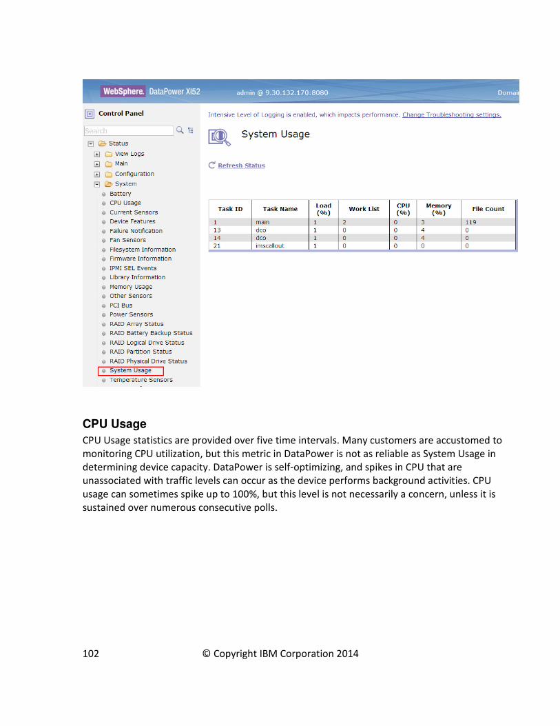
CPU Usage
CPU Usage statistics are provided over five time intervals. Many customers are accustomed to
monitoring CPU utilization, but this metric in DataPower is not as reliable as System Usage in
determining device capacity. DataPower is self-optimizing, and spikes in CPU that are
unassociated with traffic levels can occur as the device performs background activities. CPU
usage can sometimes spike up to 100%, but this level is not necessarily a concern, unless it is
sustained over numerous consecutive polls.
102 © Copyright IBM Corporation 2014

Memory Usage
Memory Usage statistics are provided for various classifications of the flash memory of the
appliance. Statistics include the percentage of total memory in use, as well as the amount of
memory in bytes that is used and free.
Again establishing a baseline before and after you introduce a given workload helps create a
context and assign a meaning for the information you collect.
The percentage of used memory depends on the application, the size of the request and
response messages, and the volume and latency of requests. Typical utilization runs less than
80%, and statistics beyond this threshold are of concern. You can use the device’s Throttle
Settings to temporarily slow down request processing or to perform a warm restart, which
recaptures memory in this situation.
103 © Copyright IBM Corporation 2014

104 © Copyright IBM Corporation 2014
Data maps with WebSphere Transformation ExtenderWebSphere Transformation Extender (WTX) is recommended for DataPower to support data
transformation for synchronous callout requests from IMS. Using WTX, you generate and deploy
the data transformation maps that DataPower uses to transform a callout request from the data
format used in IMS to the data format used by the data or service provider on the DataPower
backside.
You build and deploy the maps by using the WTX Map Designer. The WTX maps are then
deployed in DataPower.
Before you create a map in WTX, you need to create type trees that define both the data format
used in IMS and the data format used by the backside service. You use the WTX Type Designer to
create the type trees.
For detailed information about creating data transformation maps and type trees, refer to the
WTX documentation in the WebSphere Transformation Extender information center at
http://www.ibm.com/support/knowledgecenter/SSVSD8/welcome.
The high-level steps that are required to generate the maps that enable DataPower to transform
data between IMS transaction and Web Services include:
1. Importing into WTX the COBOL copybook or PL/I Imports of the IMS application program
2. Generating the XML schema or importing the XML schema from the Web Service
3. Creating the type trees for the COBOL or PL/I and the XML schema
4. Creating the compiled map
5. Testing the map locally in WTX
6. Deploy and use the map in DataPower
Creating a type tree in WTX
A Type Tree is a metadata description of input or output data. A Type Tree also contains
metadata about your data format and provides this information to your map source.
Copy your input source into the project directory in Design Studio.
To create a Type Tree, open WebSphere Transformation Extender Design Studio. Right click on
your project and select Import. Follow the import directions and point to your input file; click
Finish to create your Type Tree.
You should see a type tree file (.mtt) in your Type Trees folder:
105 © Copyright IBM Corporation 2014
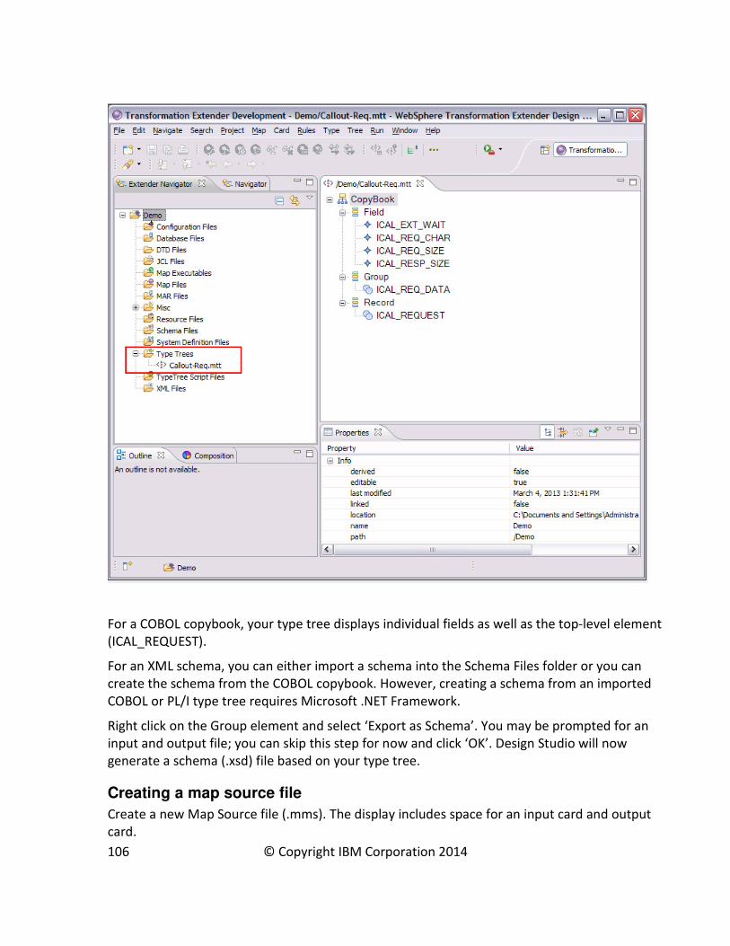
For a COBOL copybook, your type tree displays individual fields as well as the top-level element
(ICAL_REQUEST).
For an XML schema, you can either import a schema into the Schema Files folder or you can
create the schema from the COBOL copybook. However, creating a schema from an imported
COBOL or PL/I type tree requires Microsoft .NET Framework.
Right click on the Group element and select ‘Export as Schema’. You may be prompted for an
input and output file; you can skip this step for now and click ‘OK’. Design Studio will now
generate a schema (.xsd) file based on your type tree.
Creating a map source file
Create a new Map Source file (.mms). The display includes space for an input card and output
card.
106 © Copyright IBM Corporation 2014

If you don’t see your input or output card displayed here, click either New input card or New
output card.
To edit an input card, right click on the input card to display the editing panel, which is shown in
the following figure.
107 © Copyright IBM Corporation 2014

Unit Testing the map
To unit test your map with input data, change ‘Source’ to File and specify the location of your
input file. In this example, the input data is in bytes in a flat file (input.txt). You will need to do the
same to the output card, only specifying an output file (output.xml in this case). The map will
transform the data format specified in the input card into the data format specified in the output
card.
108 © Copyright IBM Corporation 2014
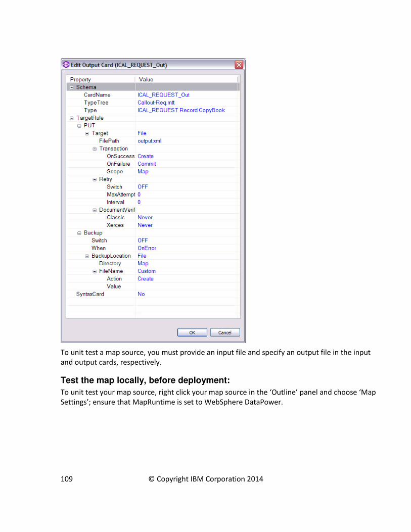
To unit test a map source, you must provide an input file and specify an output file in the input
and output cards, respectively.
Test the map locally, before deployment:
To unit test your map source, right click your map source in the ‘Outline’ panel and choose ‘Map
Settings’; ensure that MapRuntime is set to WebSphere DataPower.
109 © Copyright IBM Corporation 2014

Then right click on the map source again and click ‘Build’. If the build is successful, a DataPower
artifact (.dpa) is generated. Now you can test the file locally by selection ‘Run Locally’.
110 © Copyright IBM Corporation 2014
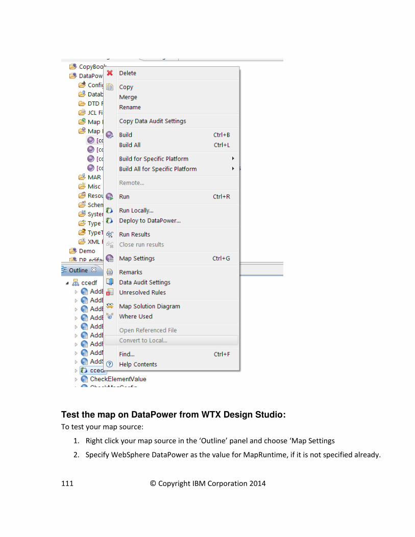
Test the map on DataPower from WTX Design Studio:
To test your map source:
1. Right click your map source in the ‘Outline’ panel and choose ‘Map Settings
2. Specify WebSphere DataPower as the value for MapRuntime, if it is not specified already.
111 © Copyright IBM Corporation 2014

3. Right click on the map source and click Build. If the build is successful, a DataPower map is
generated that has a .dpa file extension.
4. To test the file on DataPower, select Run.
Connect WTX to DataPower
Before you can deploy a map to DataPower, WTX must be connected to DataPower.
To connect WTX to DataPower:
1. Go to Window->Preferences
2. Expand Transformation Extender > Map and select DataPower.
3. Enter your DataPower address information.
112 © Copyright IBM Corporation 2014
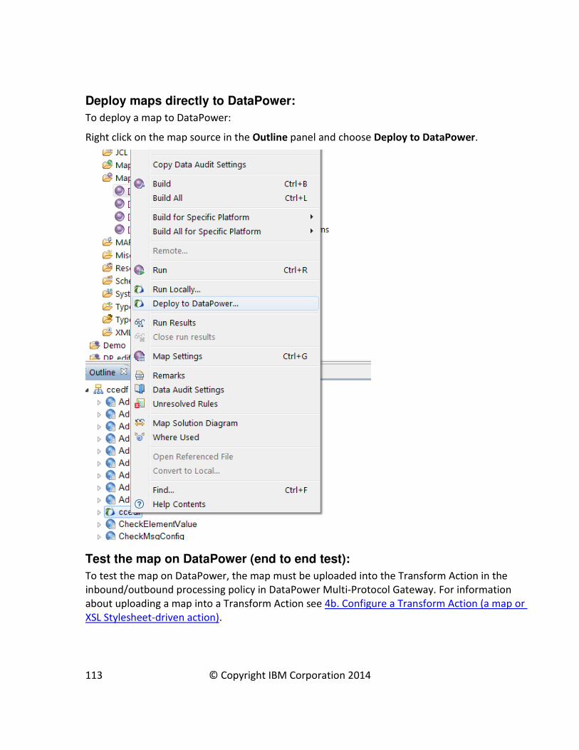
Deploy maps directly to DataPower:
To deploy a map to DataPower:
Right click on the map source in the Outline panel and choose Deploy to DataPower.
Test the map on DataPower (end to end test):
To test the map on DataPower, the map must be uploaded into the Transform Action in the
inbound/outbound processing policy in DataPower Multi-Protocol Gateway. For information
about uploading a map into a Transform Action see 4b. Configure a Transform Action (a map or
XSL Stylesheet-driven action).
113 © Copyright IBM Corporation 2014