data sheet trouble shooting liquid level sensors, aks 4100...
TRANSCRIPT

AKS 4100/4100U - Coaxial VersionAKS 4100/4100U - Cable Version
Data sheet
Trouble shooting Liquid level sensors, AKS 4100/4100U
DKRCI.PD.SC0.D4.02 | 520H9647 | 1© Danfoss | DCS (MWA) | 2017.01
Product identification From the gray label the readings listed below must be noted.These are used for on-site identification of hardware/software compatibility and for dialog with Danfoss:
The AKS 4100/4100U liquid level sensor is designed specifically to measure liquid levels in a wide range of refrigeration applications.
The AKS 4100/4100U liquid level sensor is based on a proven techhology called Time Domain Reflectometry (TDR) or Guided Micro Wave.
AKS 4100/4100U liquid level sensor can be used to measure the liquid level of many different refrigerants in vessels, accumulators, receivers, standpipes, etc.
The electrical output is a 2-wired, loop powered 4-20 mA output signal, which is proportional to the refrigerant liquid level.
HMI display readings The label readings above together with the software stated configuration will identify any possible compatibility problem between the HMI and the converter.
To manually get the software versions of the converter, sensor and HMI please follow the steps on page 2.
Compatibility
HMI
Converter
Display after power on.
1. Code number
2. Serial number (last 6 digits)
3. Manufacturing date
Data sheet | Trouble shooting - Liquid level sensors, AKS 4100/4100U
© Danfoss | DCS (MWA) | 2017.01 DKRCI.PD.SC0.D4.02 | 520H9647 | 2
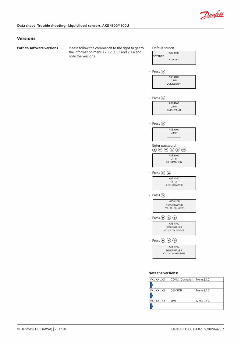
Path to software versions Please follow the commands to the right to get to the Information menus 2.1.2, 2.1.3 and 2.1.4 and note the versions.
Default screen
• Press
• Press
• Press
Enter password:
• Press
• Press
• Press
• Press
AKS 4100DISTANCE
5000 mm
AKS 41001.0.0
QUICK START
AKS 41002.0.0
SUPERVISOR
AKS 41002.0.0
__________
AKS 41002.1.0
INFORMATION
AKS 4100
QUICK SETUP ?
YES NO
Versions
AKS 41002.1.0
INFORMATION
AKS 41002.1.0
INFORMATION2.1.2
AKS 41002.1.0
INFORMATIONxxxx mm
AKS 41002.1.0
INFORMATION
AKS 41002.1.0
INFORMATIONCON.FIRM.VER
AKS 41002.1.0
INFORMATION
AKS 41002.1.0
INFORMATIONAKS 4100
2.1.0INFORMATION
AKS 41002.1.0
INFORMATION
CON.FIRM.VERVX . XX . XX CONV
AKS 41002.1.0
INFORMATION
AKS 41002.1.0
INFORMATIONAKS 4100
2.1.0INFORMATION
AKS 41002.1.0
INFORMATION
SEN.FIRM.VERVX . XX . XX SENSOR
AKS 41002.1.0
INFORMATION
AKS 41002.1.0
INFORMATIONAKS 4100
2.1.0INFORMATION
AKS 41002.1.0
INFORMATION
HMI.FIRM.VERVX . XX . XX HMI EGFS
VX . XX . XX CONV. (Converter) Menu 2.1.2
VX . XX . XX SENSOR Menu 2.1.3
VX . XX . XX HMI Menu 2.1.4
Note the versions:
Data sheet | Trouble shooting - Liquid level sensors, AKS 4100/4100U
© Danfoss | DCS (MWA) | 2017.01 DKRCI.PD.SC0.D4.02 | 520H9647 | 3
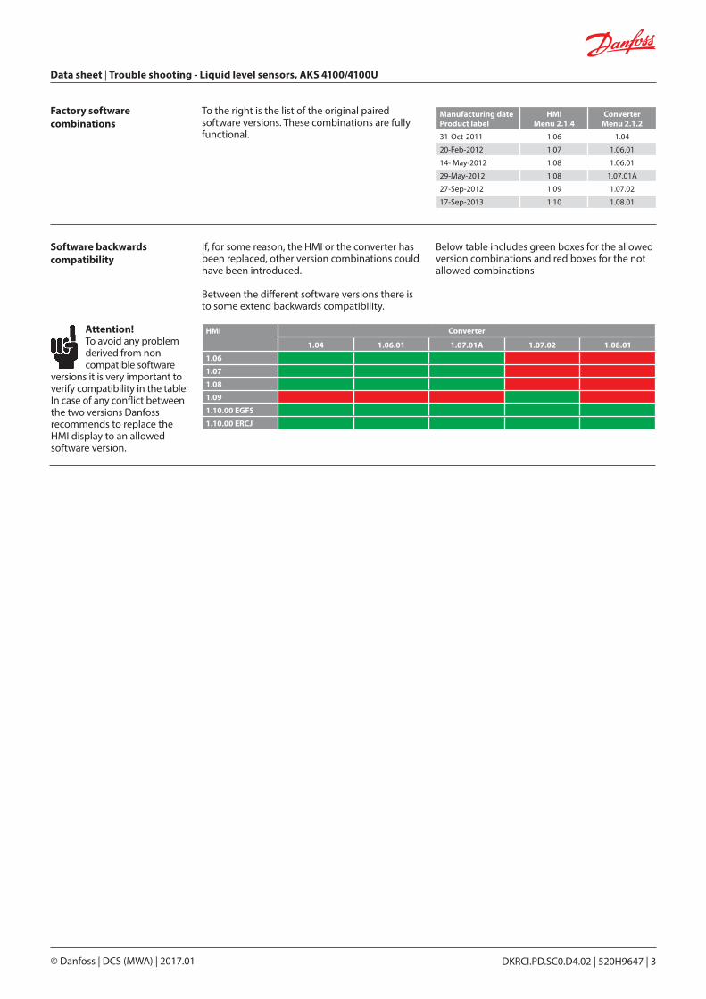
Factory software combinations
To the right is the list of the original paired software versions. These combinations are fully functional.
Manufacturing date Product label
HMIMenu 2.1.4
ConverterMenu 2.1.2
31-Oct-2011 1.06 1.04
20-Feb-2012 1.07 1.06.01
14- May-2012 1.08 1.06.01
29-May-2012 1.08 1.07.01A
27-Sep-2012 1.09 1.07.02
17-Sep-2013 1.10 1.08.01
Software backwards compatibility
If, for some reason, the HMI or the converter has been replaced, other version combinations could have been introduced.
Between the different software versions there is to some extend backwards compatibility.
Below table includes green boxes for the allowed version combinations and red boxes for the not allowed combinations
HMI Converter
1.04 1.06.01 1.07.01A 1.07.02 1.08.01
1.06
1.07
1.08
1.09
1.10.00 EGFS
1.10.00 ERCJ
Attention! To avoid any problem derived from non compatible software versions it is very important to verify compatibility in the table. In case of any conflict between the two versions Danfoss recommends to replace the HMI display to an allowed software version.

Data sheet | Trouble shooting - Liquid level sensors, AKS 4100/4100U
© Danfoss | DCS (MWA) | 2017.01 DKRCI.PD.SC0.D4.02 | 520H9647 | 4
Cable version The cable version is sensitive to variations of the surrounding geometry and materials.
Essential is to avoid these situations:- Variations in standpipe diameter. In such cases Danfoss recommend the coaxial version.- Cable not straightening out (missing or hanging counterweight) or cable touching intruding parts/tubing.- Standpipe made of non-metallic material. Danfoss recommend the coaxial version.
If you are not sure whether the geometry is regular, Danfoss recommend the use of the coaxial version.
Mechanical
Dan
foss
M84
H00
88_1
Mechanical assembly It is important to keep the cavity in the upper cable connector dry and clean at all time prior to assembly. For this purpose the packaging includes a red cap to cover the top part.
To secure the correct assembly of the converter and cable connector a vertical press to the converter is needed. A mechanical stop indicates the right vertical position.
Remember to tighten the Allen key set bolt with 10 Nm during press down.
DanfossM84H0031_1
Dry and clean cavity
Press down to the mechanical stop

Data sheet | Trouble shooting - Liquid level sensors, AKS 4100/4100U
© Danfoss | DCS (MWA) | 2017.01 DKRCI.PD.SC0.D4.02 | 520H9647 | 5
Electrical requirements(Power supply voltage)
The Signal converter requires a stable and pure DC power supply.
To check the power quality connect a voltmeter + and – terminals to the + and – terminals of the converter (+ to +, – to –) and keep this wiring throughout below testing.
Set the Voltmeter to DC Voltage. The DC readings must be in the range of 14-30 V.
Switch the Voltmeter to AC Voltage. The AC readings must be lower than 5 V.
If AC readings are above 5 V, the power supply does not meet the required quality.
Electrical
DanfossM84H0009_1
Connector for HMI
Signal current Depending on the wiring between the AKS 4100 and the controller - PLC or EKC/EKE 347 - the signal current can vary.
It is important to have sufficient and identified current to the controller. Below is the path to a controlled forced mA output from the AKS 4100.
Just follow below commands and compare the readings of the forced mA output with the readings in the controller.Remember to measure all current output possibilities of the AKS 4100. These are: 3.5, 4, 6, 8, 10, 12, 14, 16, 18, 20 and 22 mA.
If connected to EKC 347 controller:Read the parameter u30 in EKC for comparison of the forced mA output of the AKS 4100.
If connected to PLC controller:Ask local operator how to read incoming current and compare.
Note!Not all controllers allow a current signal below 4 mA from the AKS 4100. A configured lowest signal of 3.5 mA will in these cases often result in an error reading on the controller.
Default screen
• Press
• Press
• Press
Enter password:
AKS 4100DISTANCE
5000 mm
AKS 41001.0.0
QUICK START
AKS 41002.0.0
SUPERVISOR
AKS 41002.0.0
__________
AKS 41002.1.0
INFORMATION
AKS 41002.2.0TESTS
AKS 41002.2.1
SET OUTPUT
AKS 4100SET OUTPUT
3.5 mA
AKS 4100SET OUTPUT
8 mA
AKS 4100DISTANCE
5000 mm
• Press
• Press
• Press
The HMI reading is now 3.5 mA. Compare with the controller and assure the controller reading is 3.5 mA.
• Press or to scroll to any value of mA in the above shown list. Note matching readings from the controller in the table to the right.
• Press 4 times to return to default screen.
Default screen appears:
Forced mA completed and disabled
How to force mA output
AKS 4100
QUICK SETUP ?
YES NO
1. V DC
2. VAC
AKS 41002.1.0
INFORMATIONXXXX mm
AKS 41002.1.0
INFORMATIONXXXX mm
AKS 4100SET OUTPUT
8 mA
AKS 41002.1.0
INFORMATION4 mA
AKS 41002.1.0
INFORMATION22 mA
HMI reading mA Controller reading mA3.5468
10121416182022

Data sheet | Trouble shooting - Liquid level sensors, AKS 4100/4100U
© Danfoss | DCS (MWA) | 2017.01 DKRCI.PD.SC0.D4.02 | 520H9647 | 6
System fault location
Symptom Possible cause ActionRebooting - Not possible to access the setup menu.- Crash or reboot after accessing the setup menu.- Showing “Starting up...” continuously.- Configurations are not saved.
a) Incompatible software versions in HMI and converter respectively. See table on page 2.
Identify potential conflict between softwares as described on pages 1 and 2.
If not possible to get to Information menu (2.1.2 to 2.1.4) identify the converter from the label and test a HMI which for sure is compatible.
No reaction/ Frozen level- Device stays on level ~ 80%, seems “frozen”
a)
b)
c)
Non-regular geometry of the standpipe (see page 3)
Standpipe dimensions out of specification (see Danfoss installation guide)
Manufacturing date before Sept. 2013
Increase the parameter blocking distance or detection delay up to the level frozen value (see Danfoss installation guide).The value of the blocking distance/ detection delay must be outside the measuring range.
If the values of blocking distance/ detection delay cannot be increased further replace the AKS 4100 to a coaxial type (if cable type) or an AKS 4100 (any type) produced after Sep. 2013.
Black-/ interrupted display- After HMI connection - no display.- No access to converter setup.
a) Interrupted cable wiring between HMI and converter.
Check the flat cable and connector.
Replace the HMI according to compatibility table on page 2.
Unstable/ wrong measurements - Periodic fluctuating measurements.
a)
b)
Incompatible softwares between HMI and converter.
Inductor problem on early versions.
Check the compatibility according to table on page 2.
Replace with the latest HMI version.
Moisture in display- Water leaking through glass sealing.
a) Early versions less water resistant. Replace with the latest HMI version.
Smell of NH3
- Leakage inside-out of Ammonia- Display window discolored/ lost transparency
a) Weak sealings in some early versions. HMI 1):Replace the HMI with a new version.
Mechanical process connection:Date code before February 2013:Replace the mechanical process connection with a new version.
Date code after February 2013:No need to replace the mechanical process connection
1) Please note! - HMI replaced after March 16, 2014 and marked externally with an “A” - Mechanical process connection replaced after February 2013 and marked with a date code.
A small amount of ammonia may still be smelled when HMI is dismounted. This represent no safety risk. All components are well protected and the AKS 4100/4100U continues to measure and send the 4-20 mA signal corresponding to the liquid level.

Data sheet | Trouble shooting - Liquid level sensors, AKS 4100/4100U
© Danfoss | DCS (MWA) | 2017.01 DKRCI.PD.SC0.D4.02 | 520H9647 | 7
Prior to contacting Danfoss; please collect these data:
Code number
Serial number
Manufacturing date
Software versions Converter (2.1.2)
Sensor (2.1.3)
HMI (2.1.4)
Probe length (2.3.4)
Blocking distance (2.3.2)
4 mA (2.4.3) = mm
20 mA (2.4.4) = mm
Coaxial or Cable
Refrigerant
Refrigerant temperature
Refrigerant pressure
Data from the grey product label.
Data from HMI menu
© Danfoss | DCS (MWA) | 2017.01 DKRCI.PD.SC0.D4.02 | 520H9647 | 8
Notes